DEPARTMENT OF ELECTRICAL ENGINEERING …web.mit.edu/6.101/www/s2015/quiz_2014.pdf= 16pF C1 = 160 nF...
14
Name: Date: 1 Spring 2014 6.101 Quiz DEPARTMENT OF ELECTRICAL ENGINEERING AND COMPUTER SCIENCE MASSACHUSETTS INSTITUTE OF TECHNOLOGY CAMBRIDGE, MASSACHUSETTS 02139 Spring 2014 Quiz 6.101 Introductory Analog Electronics Laboratory NOTE: SHOW ALL CALCULATIONS FOR ALL ANSWERS BUT THE MOST OBVIOUS! [This will allow for partial credit for wrong answers.] Please look through the whole quiz before beginning. There are lots of questions, but most of them are very easy. It’s always good test-taking procedure to look over the whole quiz before deciding where to start, and so you can plan your time. To receive full credit values must also indicate units eg; volts, mv, ma, uF, pF, sec, ms, ohm, mohm, mHz, etc 1 sheet double sided handwritten notes only. If needed, you may use these values for constants V T (thermal voltage at 25 deg C) = kT/q = 26mv pi = 3.14, sqrt(2) = 1.41 Problem 1 /10 Problem 2 /5 Problem 3 /7 Problem 4 /10 Problem 5 /15 Problem 6 /16 Problem 7 /10 Problem 8 /10 Problem 9 /4 Problem 10 /13 Total
Transcript of DEPARTMENT OF ELECTRICAL ENGINEERING …web.mit.edu/6.101/www/s2015/quiz_2014.pdf= 16pF C1 = 160 nF...

Name: Date:
1 Spring 2014 6.101 Quiz
DEPARTMENT OF ELECTRICAL ENGINEERING AND COMPUTER SCIENCE
MASSACHUSETTS INSTITUTE OF TECHNOLOGY CAMBRIDGE, MASSACHUSETTS 02139
Spring 2014 Quiz
6.101 Introductory Analog Electronics Laboratory
NOTE: SHOW ALL CALCULATIONS FOR ALL ANSWERS BUT THE MOST OBVIOUS! [This will allow for partial credit for wrong answers.]
Please look through the whole quiz before beginning. There are lots of questions, but most of them are very easy. It’s always good test-taking procedure to look over the whole quiz before deciding where to start, and so you can plan your time. To receive full credit values must also indicate units eg; volts, mv, ma, uF, pF, sec, ms, ohm, mohm, mHz, etc 1 sheet double sided handwritten notes only. If needed, you may use these values for constants
VT (thermal voltage at 25 deg C) = kT/q = 26mv
pi = 3.14, sqrt(2) = 1.41
Problem 1 /10 Problem 2 /5 Problem 3 /7 Problem 4 /10 Problem 5 /15 Problem 6 /16 Problem 7 /10 Problem 8 /10 Problem 9 /4 Problem 10 /13
Total

2 Spring 2014 6.101 3/20/2014
Question 1 [10 points]
1a [2 point] What kind of source should this circuit be driven with in order to produce a resonant current response? _________________________________________________________________________________ 1b [3 point] What is the total value of capacitance needed to produce resonance at 500 kHz?_________________ 1c [3 point] What is the bandwidth (Hz) of this circuit? 1d [1 point] Suppose we want to change the bandwidth of this circuit to 20 kHz [+/- 10 kHz]. What component do we change ? 1e [1 point] Write the expression for the value of the component in 1d. You do not need to calculate the numerical value.
C
R = 50
L = 100 H

3 Spring 2014 6.101 3/20/2014
Question 2 [5 points]
2a [2 point] What is the color code for the 1K resistor? ______________________________________ 2b [3 point] Given that the source resistance ro of the generator is very, very large with respect to the other resistances in the circuit, and that the bandwidth of the circuit is 10kHz, what is RPara ?
5:1
700 pFRL=1k
SECRPara ro100 H

4 Spring 2014 6.101 3/20/2014
Question 3 [7 points] For the circuit below, the load resistor (not shown) attached to Vout is very large and can be ignored. The capacitors are of equal value. The forward diode drop is 0.6V.
The input voltage is Vin = f(t) = Asin(Bt). Find A and B for Vin. [ 3 points] A = B = Vout [exact value] = ____________________________________________________[4 points]
5 Spring 2014 6.101 3/20/2014
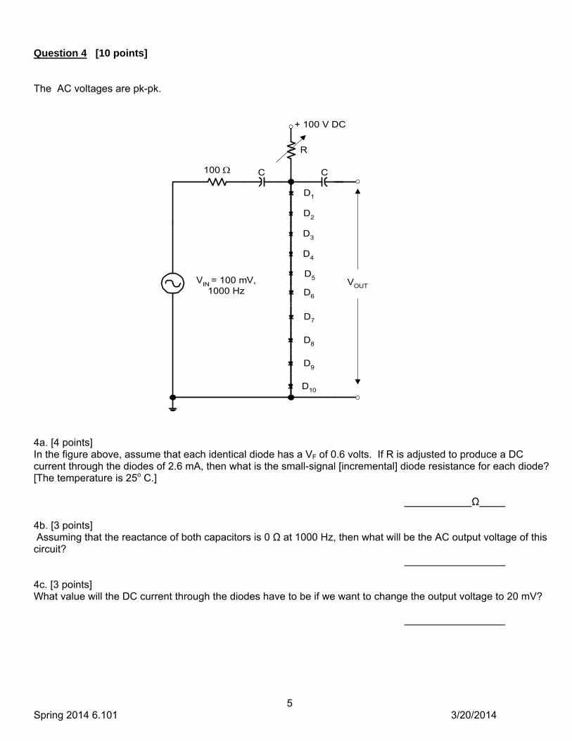
Question 4 [10 points] The AC voltages are pk-pk.
4a. [4 points] In the figure above, assume that each identical diode has a VF of 0.6 volts. If R is adjusted to produce a DC current through the diodes of 2.6 mA, then what is the small-signal [incremental] diode resistance for each diode? [The temperature is 25o C.] Ω 4b. [3 points] Assuming that the reactance of both capacitors is 0 Ω at 1000 Hz, then what will be the AC output voltage of this circuit? 4c. [3 points] What value will the DC current through the diodes have to be if we want to change the output voltage to 20 mV?
100
D1
D2
D3
D4
R
C
+ 100 V DC
VOUTVIN = 100 mV,
1000 Hz
C
D5
D6
D7
D8
D9
D10

6 Spring 2014 6.101 3/20/2014
Question 5 [15 points]
F = o = 100
5a. [4 points] Design a biasing circuit [R1 and R2] using the “stiff” biasing approach i.e. make the current through R1 & R2 equal to 20 times IB [not including the value of IB that flows through R2]; that will give only a 5% error. Assume VBE = 0.6 volts, and IE = IC. R1 = R2 = 5b. [4 points] Determine the two AC equivalent circuit parameters/elements. gm = r = 5c. [2 points] Find the input impedance to the transistor alone, looking into the base, between base and ground. Ignore the effects of the biasing network. RinQ = 5d. [3 points] Find the total input impedance for the whole circuit, taking into account your answer to 5c above and including the effects of your biasing network. Rin = 5e. [2 points] Find the voltage gain Av = Vout/Vin of this circuit at 1000 Hz. Ignore any effects due to the input capacitor. Av =
+25 V
vin
+
-
R2
2N3904
10 kR1
C
+
vout
-
1.2mA
50

7 Spring 2014 6.101 3/20/2014
Question 6 [16 points]
For the circuit below, assume both npn and pnp transistors have a gain of 200 and Vbe=0.6V.
For these questions, we are looking at quiescent values.
6a [2 points]
What is the voltage at node n1? _________________________________________________
6b [2 points]
What is the voltage at node n2?__________________________________________________
6c [2 points]
What is the current through R1?___________________________________________________
6d [3 points]
What is the voltage at node n3?___________________________________________________
6e [3 points]
What is the current through R3? ___________________________________________________
6f [4 points]
What is Vout?__________________________________________________________________

8 Spring 2014 6.101 3/20/2014
Question 7 [10 points]
The closed-loop frequency response for the circuit above is shown on the next page. Answer the following questions from looking at the next page or the schematic. 7a. What is the high-frequency corner frequency [–3dB point] for this circuit? fHI = [1]
7b. What is the low-frequency corner frequency [–3dB point] for this circuit? fLO = [1]
7c. What is the midband [1000 Hz] voltage gain for this amplifier in dB? Av = [1]
7d. What is the midband [1000 Hz] voltage gain for this amplifier,
expressed as a dimensionless multiplier? Av = [1]
7e. Above what frequency will this circuit make a good integrator? f = [1]
7f. In terms of dB per octave, what is the high frequency rolloff above fHI? [1]
7g. Calculate the required value for R1. R1 = [1]
7h. Calculate the required value for R2. R2 = [1]
7i. What is the gain-bandwidth product for the LT1124? GBW = [1]
7j. If we remove C2, what will be the high frequency –3dB point for this circuit? fHI = [1]
+vout
–
–
+
LT1124
2
3
4
7
6
R2
+15
-15
0.1F
0.1F
C2 = 16pF
R1C1 = 160 nF
+
vin1–

9 Spring 2014 6.101 3/20/2014

10 Spring 2014 6.101 3/20/2014
Question 8 [10 points]
8a. [6 points]
Choose values for these two components that will give a voltage level of exactly 1.5 volts
[3.0 volts peak-to-peak] at node n3.
8b [4 points]
Sketch on the same time scale, the voltages at nodes n1 and n2. Label the voltage levels for n1 and n2.

11 Spring 2014 6.101 3/20/2014
Question 9 [4 points]
-
+
+15
IDEAL
2
3 4
7
6 vout
-15
I–
I+
Give the following ac characteristics for the op-amp shown at left: ROUT = RIN = AVOL = I+ = I- =
Question 10 [13 points] You are building a 0-25V DC power supply for home use. Using a 0-30V meter would not give good resolution when the voltage is less than 10V. So you use a 0-15V meter with a X2 multiplier. When the X2 LED is on, the meter reading is should be scaled up by a factor of two. For example an output of 20V would show as 10V with the X2 led on. An output of 10V would show as 10V with the X2 LED off.
Assume the meter can be modeled as a pure 10k resistor with deflection proportional to the voltage. You have available any number of ideal op-amps that operate from 15 VDC with rail to rail output, resistors, capacitors, 2N7000 MOSFET and/or 2N2222 (PN2222) npn bjt. (Datasheets attached). Design your circuit including driving the LED. Assume the LED on current is 15ma. Keep in mind that an analog meter and human eye have limited resolution. As result, it is hard to discern for example 10.1V from 10.0V. There are multiple solutions to this problem. This is an actual power supply.

12 Spring 2014 6.101 3/20/2014
Circuit Diagram for driving the meter and LED

13 Spring 2014 6.101 3/20/2014
2N7000

14 Spring 2014 6.101 3/20/2014