Depar f Mech a Engineering / Japary 20, 2006 Accepted A ...
35
Design of a Dry Sump Lubrication System for a Honda® CBR 600 F4i engine for Formula SAE applications by Ehsan Farkhondeh Submitted to the Department of Mechanical Engineering in Partial Fulfillment of the Requirements for the Degree of Bachelor of Science at the Massachusetts Institute of Technology February 2006 © 2006 Ehsan Farkhondeh All Rights Reserved MASSACHUETS INSTITUTE OF TECHNOLOGY AUG 0 2 2006 LIBFRARIES Signature of Author............................................................. ......................... ............. ............ Depar f Mech a Engineering / Japary 20, 2006 Certified by .................................. rey Daniel Frey Professor of Mechanical Engineering Thesis S pervisor Accepted ........ by..... Accepted by ..... ...... ................................. .................. John H. Lienhard V Professor of Mechanical Engineering Chairman, Undergraduate Thesis Committee ARCHIw 1 II I I I --
Transcript of Depar f Mech a Engineering / Japary 20, 2006 Accepted A ...

Design of a Dry Sump Lubrication System for a Honda®CBR 600 F4i engine for Formula SAE applications
by
Ehsan Farkhondeh
Submitted to the Department of Mechanical Engineering inPartial Fulfillment of the Requirements for the Degree of
Bachelor of Science
at the
Massachusetts Institute of Technology
February 2006
© 2006 Ehsan FarkhondehAll Rights Reserved
MASSACHUETS INSTITUTEOF TECHNOLOGY
AUG 0 2 2006
LIBFRARIES
Signature of Author............................................................. ......................... ............. ............Depar f Mech a Engineering
/ Japary 20, 2006
Certified by .................................. reyDaniel Frey
Professor of Mechanical EngineeringThesis S pervisor
Accepted ........by.....A ccepted by ..... ...... ................................. ..................John H. Lienhard V
Professor of Mechanical EngineeringChairman, Undergraduate Thesis Committee
ARCHIw 1
II
III
--

Design of a Dry Sump LubricationSystem for a Honda® CBR 600 F4i
engine for Formula SAE applications
by
Ehsan Farkhondeh
Submitted to the Department of Mechanical Engineering onJanuary 20th, 2006 in Partial Fulfillment of the Requirements
for the Degree of Bachelor of Science in MechanicalEngineering
ABSTRACT
A dry sump lubrication system for a Formula SAE race car was designed andmanufactured in order to gain the various advantages this type of system affords. A drysump system stores oil in an external tank and pumps it between the engine and tank asneeded. This allows for a shallower oil pan, which permits lower engine placement. Thislower placement improves handling through a lower center of gravity. Additionally, thehighly stressed racing engine, a Honda CBR 600 F4i, receives more constant lubricationthan a conventional wet sump system. The system included design of a new pan, tankand the associated bracketry and hoses that are needed to make the system functional.The design of the system stressed reliability while keeping an eye on weight to minimizeit whenever possible. Detailed analysis and the methodology driving the design choicesare presented here along with simple dry sump theory. This document serves as theroadmap through the design of the first dry sump system on an MIT FSAE car. It shouldprove beneficial to the team when the official design report is created for the competition.Lastly, it will help assist future members who certainly aim to refine the package insubsequent years to make it smaller, cheaper, lighter, more reliable and simply betterperforming overall
Thesis Supervisor: Daniel FreyTitle: Professor of Mechanical Engineering
2
Table of Contents
1.0 Introduction: The Formula SAE Competition ..............................................52.0 Design Methodology and Functional Requirements ....................................83.0 Mechanical Design ........................................ 14
3.1 O il Pan . ...................................................................................... 143.2 Oil Tank ........................................ 253.3 Scavenge Pump ........................................ 283.4 Hose and Pressure Regulator ........................................ 30
4.0 Testing ............................... ......... 315.0 Conclusion ........................................ 326.0 References ........................................ 34
3

List of Figures
Figure 1: Schematic of a dry sump system ........................................................10Figure 2: Thin style oil pan ................................................................................. 16Figure 3: Modular style oil pan .............................................. 17Figure 4: CAD of tilted pan .................................................................................18Figure 5: Driver location in the frame ...............................................................19Figure 6: Comparison of 2006 and 2005 frames ............................................. 20Figure 7: Oil pan flange .............................................. 21Figure 8: CAD of completed pan .............................................. 22Figure 9: Machined urethane cores for use in sand casting pan .....................24Figure 10: CAD of oil tank .............................................. 26Figure 11: Completed oil tank .............................................. 27Figure 12: Pace Comp C oil scavenge pump ............................................. 28Figure 13: Aeroquip StartLite Hose .............................................. 30
4

1.0 Introduction: The Formula SAE Competition
Formula SAE is an intercollegiate engineering competition that challenges student
designers to design, fabricate and race a small formula style race car in a variety of static
and dynamic events. SAE stands for the Society of Automotive engineers and it is that
governing body that organizes, sets the rules, and runs the annual competitions. Since the
competition is an engineering challenge rather than a conventional race, restrictions are
very minimal compared to any other type of racing series so innovation and free-thinking
are encouraged.
As with any engineering competition, teams are ranked relative to each other in a
variety of events. The major attention grabbers are the dynamic events where the cars are
actually driven on a course to measure their performance capabilities. The other portion
of the even is the static events which includes cost judging, design judging and
marketing. To do well in the competition, a car needs to be both fast and well thought
out in order to do well in both types of events
The static events involve a combination of detailed paperwork and presentations
to professional judges and rank the teams in order of competency and completeness and
assign points accordingly. The major static event is the design judging event. The car is
carefully examined by a panel of professional automotive and racing engineers, each with
a specific area of expertise. The team gives a short presentation highlighting the
technical features of their car and then is questioned by the judges. A team with a fast car
but no details to support it will do poorly in this event. It has been said that a team could
5

bring the reigning Formula One champion's car into the design event, yet score very few
points because they do not understand the principles behind it. The top teams are then
announced and go on to the design semi-finals where more thorough presentations and
questioning occur until a winner is determined for the event. To do well in this event,
every aspect of the car needs to be considered and engineering decisions need to be well-
justified
The other vital static event is the cost event. This event comprises of three
sections- cost report, lowest cost and a manufacturing section. Well designed cars are
difficult to make cheaply, however by optimizing parts for manufacturing and coming up
with novel solutions, costs can be decreased significantly. This forces a designer to think
like a real-world engineer who is just as worried by cost as he is by performance. This
event keeps the competition from spiraling into a monetary battle to see which school can
raise the most funds in order to use the most exotic materials and parts. It helps level the
playing field and allows many schools to compete with needing huge bank accounts.
The marketing section is less related to the design of the car and more an exercise
in putting together a coherent marketing strategy. It has very little influence on the
design of most parts of the car, save those that significantly affect the appearance. Even
in those cases, performance is the first requirement since it is more important that a
racing car drive fast, not just look it.
The dynamic events are the exciting portion of the competition and where the
teams can directly see how they stack up against the others. The first event is an
acceleration event. The cars cover a 75-yard straight course as fast as possible in order to
6

judge engine power, gearing and traction. Top cars tend to hit over 60 mph at the end
and cover the distance in just over 4 seconds.
The skidpad event determines a car cornering ability. The car is driven around a
small diameter circle as fast as possible with the lowest elapsed time team finishing first.
There are two circles which force the car to be driven in both directions in order to
determine actual overall handling ability. Otherwise, the teams would strategically shift
weight if the skidpad were only run in one direction.
The two big events are autocross and endurance. The autocross is a racetrack that
is laid out with cones which cars cover one at a time. The course has all variety of
features including straight-aways, braking zones, slaloms and most types of corners. It
tests the overall performance of a car and the skill of drivers to drive an unknown course
quickly the first time through since the event is a one-lap only event. This is the true test
for these cars since they are built to single seat cars that compete in SCCA autocross
events.
The endurance is similar to the autocross, though the layout allows for higher
average speeds and the cars run multiple laps in order to cover approximately 22
kilometers. This is a torture test of the cars reliability as only between 1/3 to 1/2 of the
cars finish the endurance event every year. Since it is the highest point scoring event, not
finishing it essentially forces the team to a non-spectacular ranking. This event is what
drives most of the physical requirements of the various parts of the car since they see the
most abuse here.
7

Table 1: Points Distribution and Total
Event Points
Design 150
Cost 100
Marketing 75
Acceleration 75
Skidpad 50
Autocross 150
Endurance 400
Total 1000
The top teams regularly score in the 800-900 point range so it is obvious to see
that in order to compete at a high level as the MIT team is aiming for, high marks must be
attained in all the events. The 2006 FSAE Official Rules has many more details about
the events, requirements and point structure.
2.0 Design Methodology and Functional Requirements
The MIT team has been tossing around the idea of a dry sump lubrication system
from the first year of the team's existence, however due to the fact that it is technically an
extraneous part not necessary to make the car function properly, it was never pursued
until this year. The system is an add-on system that changes the functionality of the stock
lubrication system of the engine to a more complicated, yet advantageous system. As a
result, some high level design goals were laid out.
8

These included making a system that is absolutely, stone-cold reliable. Since the
system replaces a perfectly functional part of an engine designed and built by a group of
professional engineers at a multi-billion dollar company, Honda, the dry sump needs to
be trouble free and not in constant need of service. The system needs to work through
dynamometer testing, vehicle test driving and naturally, the dynamic events. Since oil
lubrication of an engine is by far the most critical parameter related to engine life or
failure, there could be no problems with it or weaknesses.
Another important design goal was to minimize system weight, while still
remaining reliable. A dry sump increases overall part count on the vehicle so it adds
extra weight that never needed to be accounted for in the past. This means that the extra
parts should be made as light as possible to not negatively affect the power to weight
ratio and other advantages gained from a lightweight car. As a team, one of the goals for
the 2006 car is to reduce overall weight and that results from every component shedding
some weight.
With the overall design goals laid out, the detailed functional requirements can
then be drawn up and considered in terms of order of importance. As opposed to most
other parts on the vehicle, such as suspension or an intake which are absolutely required
to make a car perform and thus need little justification for existence, a dry sump is not
required. Instead, it is a part that helps the performance of other sections of the car and
leads to improved performance indirectly.
In order to demonstrate this, the functionality of a dry sump lubrication needs to
be explained. An engine needs lubrication in order to overcome friction in its rotating
parts and to help remove heat from inside the engine. Most production vehicles have a
9

system known as a wet sump system. In this case, the oil is stored in a deep pan at the
bottom of the engine block. The oil is then drawn into an internal pressure pump and
distributed through the engine. The MIT Motorsports team's engine, taken from a Honda
CBR600F4i, also has a wet sump. A dry sump system uses an external tank to store the
oil and uses pumps to bring the oil back and forth to the engine as needed. A schematic
is shown in Fig 1.
ScavengeOil Tank
Oil pan
Fig 1: Schematic of Dry Sump System for a Honda CBR 600 engine.
On the surface, this system seems unnecessary and overly complicated, both
qualities that are usually frowned upon in high abuse environments such as car racing.
However, a more detailed look proves the benefits of the system.
The first benefit from this system is that the engine always has a constant supply
of oil. In a wet sump, oil sloshes around due to acceleration forces just as a cup of water
can spill if it is moved too quickly. When oil sloshes around the pan, it can expose the oil
pickup to air. Air does not make a good lubricant and can only wreak havoc on an
engine's internals. This is particularly a problem on long, high speed corners when all of
10

the oil gets stuck on one side of the engine and cannot flow back to the pickup until the
corner is completed, resulting in oil starvation.
This starvation phenomenon is amplified by the fact that the engine came from a
motorcycle. In the case of a motorcycle, oil starvation is not an issue since the turning of
the bike counteracts the lateral acceleration. To clarify, consider a right hand turn being
negotiated by a motorcycle. The rider leans the motorcycle to the right, with its angle
relative to vertical being determined by the speed of the bike and the radius of the turn.
The higher the speed or the smaller the radius, the greater the lean angle needs to be.
Both those conditions also lead to more lateral acceleration from centrifugal effects. The
oil is being pushed to the outside of the turn, the left side of the engine, however because
the engine is leaned over to the right, the oil level stays essentially flat. The result is an
engine that has very little consideration in the stock setup for oil starvation so no baffles
or other methods are used to keep oil in the pan. On an FSAE car that does not lean into
corners, this can lead to problems.
The dry sump supplies oil from a tall, narrow tank. This tank is not affected by
the vehicle's acceleration and the tall height of the tank increases hydrostatic pressure
and helps force oil back into the engine. In this manner, the dry sump always keeps
constant oil pressure and saves the engine from damage. This is the biggest factor that
drives most real race cars to have a dry sump system.
Since oil is no longer stored in oil pan, it allows the pan to be made much shorter
in height. Fittings are needed to interface between the hoses and the engine and this
allows the perfect opportunity to design a new oil pan that is both smaller and includes
the fittings. The advantage here is that by reducing the height of the oil pan, the overall
11

height of the engine is now reduced. In a Formula SAE car where the engine is placed as
low as possible in order to lower the center of gravity, this allows the engine to be
mounted lower than a fully stock engine. Since the cars weigh no more than 500 pounds,
the approximately 150 pound engine represents a large percentage of that weight. By
moving this mass down, it has a profound effect on the center of gravity. This gain is
coveted by the chassis and suspension designers for a multitude of reasons beyond the
scope of this writing. However, the key conclusion is that a lower center of gravity leads
directly to improved vehicle performance.
The dry sump system has other advantages as well. The scavenge pumps create
suction in the engine case when they pump the oil to the external tank. This suction
creates a negative pressure in the crankcase which has been shown to potentially increase
power. This results because the pistons are no longer compressing any gases when they
are moving downward. This decreases resistance which helps increase power. Another
phenomena is known as windage. Windage occurs when the crankshaft rotates through
the oil in the bottom of the pan. Due to oil's high viscosity, this additional drag robs the
engine of power and only leads to increased oil temperatures. With the oil safely
removed from the engine, windage is eliminated.
Another side benefit of the dry sump system is that it removes oil from its
inhospitable location inside the engine. In this location, it is exposed to all the heat and
combustion by-products inside the engine even while it is doing no lubricating and only
waiting to be pumped through the engine again. By placing the oil in an external tank, it
places the oil is a much more docile environment where it has the opportunity to cool
down a bit and not be exposed to contaminants. The dry sump also allows oil capacity to
12
be decreased by about 25%, or in this case, 1 quart. This saves 1.8 pounds over the stock
system, which nearly offsets the additional weight of the dry sump system's parts.
With all of these advantages looking to be met, the functional requirements could
then be finalized. They included fabrication of an external tank and oil pan, running
hoses and selecting an appropriate scavenge pump.
The oil pan needed to be as short as possible in order to maximize the height
reduction of the engine. The pan also needed to contain all of the fittings necessary to
transport the oil to and from the engine. The pan would bolt into the same location of the
stock piece without modification to the engine block.
For the oil tank, it was necessary to make a part that was as light as possible but
still held onto its structural integrity. In addition, the oil coming into the tank would be
aerated and a method of de-aerating the oil was called for. The tank also would want to
contain a cap from where to fill the system and a breather valve to keep the internal
pressure at atmospheric.
The transport lines would be optimized for adequate strength and cost. Many
different options exist for high-quality hoses, but most are overbuilt for this purpose.
Finding an adequately designed system would allow for minimal weight gain. Finally,
the hoses would need to be run cleanly and well-organized in order to present the car as
professionally put together, which is key for the design judges.
It was determined early on in the project that in order to keep the scope to a
reasonable amount, a commercially available scavenge pump would be purchased.
Various ideas for creating in-house pumps were investigated but none could be made to
look elegant without extensive work and in a project where reliability is the key factor, it
13
was felt that it would be more prudent to leave the complex work of designing a pump to
an outside company. If the rest of the system proves to be reliable, then the pump can be
a point of further project development in the future.
3.0 Mechanical Design
The design of the dry sump started by creating a schematic layout of the system to
determine how to steer the major direction of the part designing. In this step,
architecture, materials, manufacturing and sizes were looked at from a high level to
ensure that the paths being chosen were feasible. A number of other teams have already
created their own custom dry sump systems so a general baseline was easy to achieve by
talking with them about their designs. Also photos of other team's parts gave ideas of
what works and what can be improved. Since dry sump systems are commonly available
for full-size production cars, informational material and off the shelf systems were also
looked at to understand the details of the system and where to start the design.
3.1 Oil pan
After consideration, the oil pan was selected as the most important module and it
was first on the docket for design work. As mentioned, it was known that the pan would
be shorter than the stock pan, but after that, many options were available. In one
extreme, there lay the completely flat oil pan that was nothing more than a 1/4 " to 1/2"
thick piece of aluminum that would cover the opening of the oil pan. It is very easy to
make since it only needs a flange and a bolt pattern cut into it and also gives the greatest
possible reduction in engine height without shaving material from the block. It is also
14

very lightweight. This design however does not deal with fittings that are needed to
remove and return the oil to the engine. In this design, the fittings are welded into the
side of the engine block near the bottom. This means that any engines that might be used
need to be prepared this way, which results in many hours of labor. This is due to the
fact that the engine should ideally be disassembled when the cutting and welding take
place. Also, welding to the cast aluminum block is not a highly desired course of action.
The drawback is that unprepared engines simply will not work with in this setup.
One unfortunate occurrence is when a team damages their engine at the annual
competition. Normally, teams make requests for parts, and an engine such as the CBR
600 is common enough that another team will loan it to them for the duration of the
event. With welded in fittings, the engines would require major re-working to fit in the
car. Fig. 2 shows another team's thin-style oil pan that obviously necessitated welded in
fittings.
Fig 2: A minimal thickness oil pan fabricated by another FSAE team
15
m_

The minimalist design certainly has its benefits but the drawbacks were deemed
too costly to pursue the idea.
The next major type of dry sump oil pan is one with the fittings integrated into the
side of the pan itself. This creates a modular design that would allow it to bolt onto any
engine without modification or disassembly. This design is the most common and an
example is shown in Fig 3.
Fig 3: A conventional, modular style dry sump oil pan made by Muzzy's for theKawasaki ZX-12R motorcycle.'
The disadvantages of this design over the flat plate style pan are that the engine
height is not reduced as much which raises the center of gravity relative to the other
design. Manufacturing of the pan is also harder because it requires more material
removal, and the complexity almost assures that it must be done with CNC machinery.
16

Weight is also greater relative to the flat plate pan so care must be taken to reduce it as
much as possible.
However by including all the features and ports in the pan, the strength of the
system is increased since the pan is machined from a block of billet aluminum. Welding
on the case can lead to pinhole leaks if the welding is not done well enough. The heating
can also change heat treatments of parts leading to parts that have compromised strength.
When trying to optimize reliability and life of the system, the conclusion usually leads to
the choice of the deeper and modular pan, which is evidenced by the majority of the
FSAE teams with dry sumps and all of the commercially available units.
Before finalizing selection of the oil pan architecture, one final look was taken at
the two designs to see their merits and see what other options were available. Looking at
the modular design, it is noted that the pan height is driven by the size of the fittings.
This means that the pan has a uniform height even though it technically only needs it in a
few certain locations where the fittings are located. Otherwise, it can be as thin as the flat
style pan. Creating a thin pan with bumps around the fittings is not useful though, since
the total height of the pan is what determines the bottom plane of the engine.
After further thought, the idea of a tilted oil pan was born. By placing all the
fittings on the same side of the pan, the opposite wall could be extremely thin and the two
other walls tapered to run between the two different heights. In this design, the bottom
plane of the pan and the flange would no longer be parallel. To position the engine as
low as possible, it would be tilted such that the bottom plane of the pan was parallel with
the ground. This design is shown in Fig 4.
17

Fig 4: Tilted style oil pan as seen from side. Rear of pan is on the right of thefigure and is the location for the fittings.
Clearly, this pan is the hybrid of the two designs and takes the advantages and
tries to discard the negatives. It still retains a modular design with the fitting in the pan
for strength and simplicity. But it also allows for lowering of the engine compared to a
regular modular pan. Another plus is the location of the additional drop. In this case, the
front of the engine is lowered further than the back. In the CBR 600, as in most inline
cylinder motorcycle engines, the crankshaft is located at the front of the motor. The
crankshaft is also the heaviest part of the engine. The result of the tilted pan is that the
heaviest portion of the engine receives the largest decrease in height. The one major
disadvantage of this design is that the machining now requires three-dimensional
machining capabilities which are far more complicated than two-dimensional milling.
Fortunately, MIT has the facilities and software tools to handle this added complexity,
but this will be discussed later in the manufacturing section.
Tilting the engine also has another key benefit in that it allows the driver to be
reclined further over the top of the engine. In 2005, the engine determined the angle to
which the driver could be reclined. Reclining the driver is beneficial since in a 600
18

pound vehicle, moving a 150 pound object further down creates further gains in lowering
the center of gravity. Of course the 150 pound object in question is the driver. Fig 5
shows the interface of the driver with the engine and the positioning of the engine in the
frame.
.rl J. I JJU31LIUIJlAl 11 Lilt; IIaUt allIU Ult IVUWUIU Ctllglll. IL Lall Ut 3ttU 11 tL Liltl
angle of the driver's back is very close to being parallel with the top of the cylinder headcover. This leads to the driver being lower than he would be without the tilted engine
design.
Further reclining the driver also allows for lowering of the main roll hoop which
is desired since it is made of 1" diameter, 0.95" wall thickness 4130 chromoly steel. This
tube is the thickest and thus heaviest on the car for safety reasons so any chance to make
it shorter is seized upon. The two inch-clearance to the driver's helmet in Fig 5 is
mandated by the rules to make the car safe in case of a rollover.
As mentioned the 2006 frame has been shrunk due to the shorter engine height.
This can be seen in Fig 6.
19

Fig 6: The 2005 frame (in lighter color and taller) laid over the 2006 frame. Note thedecreased height of the main roll hoop, which is a direct result of the dry sump. Other
changes in the frame were made for suspension considerations.
Once the general shape of the pan was determined, details of its design needed to
be addressed. 'The first task was to successfully recreate the bolt pattern in Solidworks
since that is the one part that interfaces with the engine and thus needs to match up to the
Honda specifications. The bolt pattern does not follow any set sequence or straight lines
so measuring it point to point would be difficult. Instead, it was decide to scan the flange
of the oil pan into a computer, converted into a picture and then drawn over using
Solidworks 2004-2005. This process made the creation of the part drawing much simpler
than trying to determine the points of the bolt holes in an X, Y plane. The flange is
shown in Fig 7.
20

Fig 7: Oil pan flange and bolt pattern.
In order to verify the accuracy of the bolt pattern, two methods were undertaken.
The first and most simple one was to print out the drawing in full-scale mode, cut out the
flange and see if it matched up well with the engine flange. This test was successful, but
the drawbacks were that the paper was too compliant and did not give a very detailed
result of the accuracy. The next step was to waterjet cut the flange out of a piece of 0.50"
thick aluminum. This process took only a few minutes, but resulted in a part that was
stiff enough to give meaningful results. The end conclusion was that the bolt pattern was
in fact quite accurate and machining of oil pans could go forward without fear of missing
a feature and having to start from the beginning of the fabrication process.
With shape and interface problems solved, attention was turned to the location of
the pickup ports. Even though the exit fittings were on the back of the pan, it did not
mean that they should necessarily pick up from those locations. In fact, if the two ports
only picked up from the bottom, then oil could pool up at the front of the engine during
21

braking. Larger dry sump systems use many multiple fittings and ports to pick up from
every imaginable corner. In this case, weight and packaging is at a premium so two ports
would have to suffice. To maximize their effectiveness, they were designed to pick up
from opposite corners of the pan. This would create the largest number of situations that
would still result in useful scavenging of oil from the engine while staying with only two
fittings.
The right side port was determined to be allowed to pick up from the fitting
directly. This makes for easy manufacturing and no need for internal plumbing on that
fitting. The other fitting would have its port in the front left corner of the pan. This is
accomplished by running a thin tube to that location from the fitting. The result is shown
in Fig 8 as the completed pan
Fig 8: Completed oil pan with fittings and ports.
22

The final part of the design was the return port to the engine. The stock pressure
pump is being used to supply oil to the engine so oil had to be delivered to it as it was
with the wet sump. A channel was installed in the block with a hole at the end. Into this
a tube with o-rings at both ends is placed. This tube then inserted into the pressure pump
intake and sealed with one of the o-rings. The tube is positively retained by the oil pan
thus insuring that it won't move and lead to air leaks in the system.
Manufacturing for the pan evolved with time. At first, a conventional billet
aluminum pan was planned on being fabricated with a CNC milling machine. However,
upon further analysis, it was shown that if the part could be cast, it would be significantly
cheaper on the cost report. The code for the billet aluminum version was still created and
it was determined that even with speed optimization, it would still take a minimum of 4
hours of CNC work to complete the pan. At 70$/hour, this would total at least $280 in
labor costs.
Casting a part on the other hand is far, far cheaper. For aluminum, the cost is $3
per pound of material cast. The pan weighs in at around two pounds so the process cost
would be around $6. Compared with $280, the $6 option seems a lot more desirable.
The casting would be accomplished through the process of sand casting. In order to
make the mold, a core had to be machined to give the shape and features of the pan.
Here, the previously generated CNC code came in handy. The material chosen to make
the cores is urethane foam, a material that is heavy and dense but machines with
effortless ease. Deep cuts (such as /2" deep and 5/8" diameter) can be sent along at high
feed rates (20 ipm) without any tool chatter, overheating or other maladies that occur
when trying to speed up a milling process. Thus the cores can be milled in a relatively
23

short amount of time. The advantage is that if a cast piece turns out to be unusable, a
new core can be created very quickly.
For the core, both a bottom and a top part were milled separately. A Bridgeport
EZ-Trak milling machine was used to create the first mold core. The result is shown in
Fig 9. Another advantage of the foam machining is that it allows the verification of the
CNC code, so that if it becomes necessary to go back to a billet aluminum pan, the
toolpaths will be already checked and worries about tools crashing into vices or plunging
into parts without cutting can be allayed.
Fig 9: The bottom and top halves of the core for the oil pan.
24
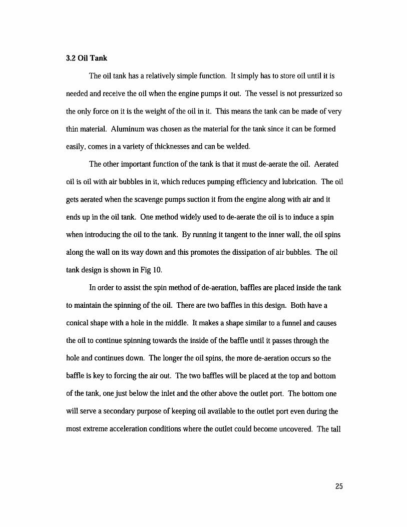
3.2 Oil Tank
The oil tank has a relatively simple function. It simply has to store oil until it is
needed and receive the oil when the engine pumps it out. The vessel is not pressurized so
the only force on it is the weight of the oil in it. This means the tank can be made of very
thin material. Aluminum was chosen as the material for the tank since it can be formed
easily, comes in a variety of thicknesses and can be welded.
The other important function of the tank is that it must de-aerate the oil. Aerated
oil is oil with air bubbles in it, which reduces pumping efficiency and lubrication. The oil
gets aerated when the scavenge pumps suction it from the engine along with air and it
ends up in the oil tank. One method widely used to de-aerate the oil is to induce a spin
when introducing the oil to the tank. By running it tangent to the inner wall, the oil spins
along the wall on its way down and this promotes the dissipation of air bubbles. The oil
tank design is shown in Fig 10.
In order to assist the spin method of de-aeration, baffles are placed inside the tank
to maintain the spinning of the oil. There are two baffles in this design. Both have a
conical shape with a hole in the middle. It makes a shape similar to a funnel and causes
the oil to continue spinning towards the inside of the baffle until it passes through the
hole and continues down. The longer the oil spins, the more de-aeration occurs so the
baffle is key to forcing the air out. The two baffles will be placed at the top and bottom
of the tank, one just below the inlet and the other above the outlet port. The bottom one
will serve a secondary purpose of keeping oil available to the outlet port even during the
most extreme acceleration conditions where the outlet could become uncovered. The tall
25

tank mitigates most of these effects, but the lightweight aluminum baffle adds negligible
weight but provides an important layer of final protection against starvation.
Fig 10: Aluminum external oil tank.
As with all other parts on the car, minimizing weight was a key goal in the oil
tank. After doing analysis, it was determined that the driving parameter for making the
lightest possible tank was manufacturing, not material strength. A carbon fiber oil tank
was briefly considered but the idea discarded due to the inability of the epoxies to deal
with the high temperatures of the oil.
The team welder was consulted and after some practice, he was able to
successfully weld 0.40" thick 6061 aluminum. Since aluminum is tricky to weld, any
thinner would have caused problems with poor welds and leaky seams. To manufacture
26

the part, it was simply rolled on a sheet metal roller to the desired diameter of 5". The
two end caps were then cut on a waterjet cutting machine to achieve perfect circles. The
whole assembly was then fitted, jigged and welded together. Subsequent tests with water
showed absolutely no leaks. After leak testing, two AN-10 fittings were welded on, one
for the outlet at the bottom, and one for the inlet near the top. Finally, the baffles were
welded in at their appropriate locations. A nearly completed tank is pictured in Fig 11.
-, l .-1 . .... ,
rig 11; Ull tanK nearing complelon. pNote tangential inter port to promote e-aerauon.
The finished oil pan weighs in at just over 1 pound, yet still feels strong and
sturdy enough to contain the oil easily. The flow rate from the outlet due to gravity has
not yet been measured, but visual observation shows that it flows fairly quickly due to the
tall and narrow design increasing the hydrostatic pressure at the bottom of the tank.
Mounts will be added once the frame of the 2006 car is completed. They will be a bolt
on bracket that has welded-on brackets on both the frame and tank. This will allow for
27
, - -- - - - - _ _ _ _
quick and easy removal of the tank if necessary but will hold it securely enough to
eliminate the possibility of it becoming detached from the car.
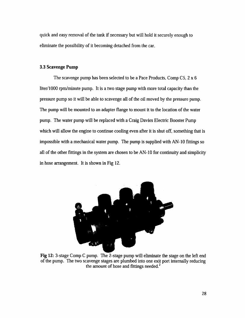
3.3 Scavenge Pump
The scavenge pump has been selected to be a Pace Products, Comp C5, 2 x 6
liter/1000 rpm/minute pump. It is a two stage pump with more total capacity than the
pressure pump so it will be able to scavenge all of the oil moved by the pressure pump.
The pump will be mounted to an adapter flange to mount it to the location of the water
pump. The water pump will be replaced with a Craig Davies Electric Booster Pump
which will allow the engine to continue cooling even after it is shut off, something that is
impossible with a mechanical water pump. The pump is supplied with AN-10 fittings so
all of the other fittings in the system are chosen to be AN-10 for continuity and simplicity
in hose arrangement. It is shown in Fig 12.
Fig 12: 3-stage Comp C pump. The 2-stage pump will eliminate the stage on the left endof the pump. The two scavenge stages are plumbed into one exit port internally reducing
the amount of hose and fittings needed.
28

For the scavenge pump to work, two piece of design and fabrication are needed.
The first is the mount that will allow it to attach to the location of the stock water pump.
The bolt pattern and shape of the water pump mount is uneven and asymmetric so a
photograph was taken and the overlaying method used to design the oil pan flange was
again used. The bolt pattern was accurately found as was the flange through which the
oil pump mates with the engine block and needs sealing. The model was then created
using a 3-D printing machine to recreate the bolt pattern and flange. The CAD model
was adjusted slightly for accuracy so there now is an accurate and tested pattern for the
mount. Once the oil pump arrives, it will allow for the measurements to be taken on the
pump side and the whole mount can be drawn in CAD and finally machined.
The other part that will be made is the stock oil pump drive shaft. The reason for
this change is that the stock internal pump and the mechanical water pump are in line
with each other and are both driven by the gear on the outside of the oil pump. The gear
transmits the torque to the oil pump shaft which turns the oil pump, but also travels
through it until it mates with the water pump shaft. The shaft on the new scavenge pump
is not shaped like the water pump, but the stages on the Pace pump are sealed so
dissembling it and changing the shaft would be difficult. Instead, the stock oil pump
comes apart very easily and the shaft is a very simple design made of steel. This shaft
can be replaced with a new one that will have the same features as the original one to
drive the oil pump, but a new mating surface to match up with the new scavenge pump.
Again, this part will be finalized once the oil pump is received. Fabrication should be a
fairly straightforward job on a manual lathe and mill.
29

3.4 Hose and Pressure Regulator
To allow all of the separate parts to function properly, a few more pieces are
needed. The most obvious part is the hoses that will transport the oil from location to
location. The standard type of hose used in racecars is the steel braided hose for its
durability and the protection afforded by the steel braiding. Areas such as the brakes or
the fuel system use steel braided line because both of those are absolutely critical to the
safety of the car. If a crash occurs or even a small piece of debris were to sever one of
these lines, the car might not be able to stop (brakes) or could spill fuel on a hot engine
and immediately catch fire. In this application however, the steel braiding is not totally
necessary. While oil is an essential fluid for the engine, it does not have nearly the same
impact on safety as the two other systems mentioned. A non-steel braided oil line could
be severed, but if it was, the only result would be a leaking of the engine oil, followed by
low oil pressure and eventual engine failure. However, the driver has a low oil pressure
light on the dash that would light up if this were to happen. The driver could then pull off
the track before damaging the engine or risking his own safety. Because of this lower
risk, fabric braided line, such as Aeroquip's StartLite can be used. The fabric braided
hose is 45% lighter than steel braided while still retaining much of the strength. This
allows for a good compromise between strength and weight and is shown in Fig 13.
Fig 13: Aeroquip StartLite Hose. The hose will be AN-10 to match the ports on thescavenge pump.3
30

The final accessory that is needed is the pressure regulator. The Honda engine is
regulated to an internal pressure of 40 psi by a regulator that dumps excess pressure back
into the wet sump pan. Unfortunately, the part is too tall to use with the new, shorter pan
so a change must be made. The engine has an oil pressure port on the right side that is
used for attaching a pressure gauge to measure oil pressure for diagnostic use. It has a
threaded insert and thus allows easy attaching of a hose with a fitting on the end. The
design calls for the stock pressure regulator to be modified to fit in a small housing that
will be in line with this hose. The hose will then be routed to the oil tank and will
function by relieving excessive pressure to the oil tank, much like the stock system. The
port on the bottom of the engine where the regulator was originally located will be
plugged with a piece of precisely machined aluminum and sealed with an O-ring to keep
oil from leaking out.
4.0 Testing
The dry sump will first be tested on an engine on a dynamometer. This will allow
for careful monitoring of parameters and makes for easier modification since the engine
is open and accessible, as opposed to when it is in the car. All parts can be observed and
oil pressures can be logged to verify full functionality of the system at various rpms and
loads. Another test that will also be run on the dyno is an Engine Oil Aeration Test
(EAOT). MIT's Sloan Automotive Laboratory has a testing unit to precisely measure the
amount of air in the oil. By using this piece of equipment, the team can show concrete
numbers on how oil aeration changed between different types of oil tanks, baffles and
other parameters that would affect bubbles in the oil. This will be a huge plus in the
31

design judging event where the judges want to see the team produce as many
experimentally measured values to back up their design choices as they can.
After the system successfully passes the static testing on the dyno, it is time for
on-vehicle testing. An AIM data logger will be used to record oil pressures. These
numbers are extremely important since it is in cornering and accelerating sequences when
the full advantages of the dry sump are realized. These conditions cannot be reproduced
on a dyno cell so on-vehicle testing is mandatory to accumulate useful, relevant results.
A successful system will keep pressure constant with the operating speed of the engine.
Fluctuating oil pressure at a constant rpm will point to starvation problems and the
system will have to be carefully inspected to locate the source of the problem. If all goes
to planned, the system will work correctly, not leak and provide constant oil pressure to
the engine.
5.0 Conclusion
After completing the design and fabrication process of the dry sump system, one
realizes that it certainly is worth the extra effort and money. All of the stacked
advantages of moving the engine down, reclining the driver and shortening the roll hoop
lead to large gains in chassis performance. This is a case of an engine modification
indirectly impacting the chassis in a positive manner
The system was centered around a reliable, yet simple implementation of a dry
sump system. Future work in creating an in-house solution for the scavenge pump has
already been started as a roots-style pump is being looked at. Further refinement of the
oil tank can be made and the casting of the oil pan can be turned into an exact art. The
32

goal for this year was to make a system that had full functionality and to test the team's
skills in building a dry sump and actually using its advantages. In subsequent years, the
system can be optimized for weight and cost, with the end goal being to bring both of
those down as far as possible. Of course if a new engine is chosen down the road, then
the parts will have to be changed, but the overall architecture can probably be retained.
One hope on the horizon is changing over to an Aprillia V.45 450 cc V-twin engine. This
engine comes with a dry sump system from the factory so it would eliminate the
necessity of this project. Nevertheless, the 2006 car is using the Honda engine so it will
still reap the benefits of the dry sump. Even in the case of the Aprillia, having solid
engineering reasons for using a dry sump, regardless of whether or not the engine came
with it, will account for more concise and educated answers to judges' questions and in
designing other parts of the racecar.
The dry sump is a multi part system that has profound effects on many other
systems on the car. If it does not work, the entire frame would need to be scrapped and
rebuilt as the stock system would grind into the road. By looking at each component of
the system selectively and determining the key features that would lead to success or
failure, the system is made to work and there exist countermeasures to any foreseeable
problems. All of these methods are simple, good engineering practices and as always is
the case in engineering, is a balancing act of compromise between performance, weight
and cost.
33

6.0 References
1 Muzzy's ZX-12 Dry Sump Conversion Kit. [Online Document]. Available HTTP:http://www.muzzys.com/ZX 12_Dry_Sump/ZX- 1 2Dry_Sump.jpg
2 Pace Compact C Pump. [Online Document]. Available HTTP:http://paceproducts.co.uk/images/products/oilpump/compactc.jpg
3 Aeroquip StartLite Hose [Online Document]. Available HTTP:http://www.huntsvilleengine.com/pictures/Start%20OLite%20OHose.jpg
34

MITLibrariesDocument Services
Room 14-055177 Massachusetts AvenueCambridge, MA 02139Ph: 617.253.5668 Fax: 617.253.1690Email: [email protected]: //libraries. mit. edu/docs
DISCLAIMER OF QUALITY
Due to the condition of the original material, there are unavoidableflaws in this reproduction. We have made every effort possible toprovide you with the best copy available. If you are dissatisfied withthis product and find it unusable, please contact Document Services assoon as possible.
Thank you.
Some pages in the original document contain colorpictures or graphics that will not scan or reproduce well.