
DELUXE STITCHER · Before using this Stitcher Head, all operators must study this manual and follow...
48
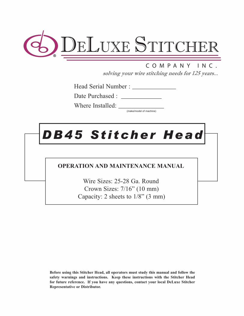
Before using this Stitcher Head, all operators must study this manual and follow the safety warnings and instructions. Keep these instructions with the Stitcher Head for future reference. If you have any questions, contact your local DeLuxe Stitcher Representative or Distributor. DB45 Stitcher Head OPERATION AND MAINTENANCE MANUAL Wire Sizes: 25-28 Ga. Round Crown Sizes: 7/16” (10 mm) Capacity: 2 sheets to 1/8” (3 mm) Head Serial Number : Date Purchased : Where Installed: (make/model of machine) DELUXE STITCHER COMPANY INC. ® solving your wire stitching needs for 125 years...
Transcript of DELUXE STITCHER · Before using this Stitcher Head, all operators must study this manual and follow...
Before using this Stitcher Head, all operators must study this manual and follow the safety warnings and instructions. Keep these instructions with the Stitcher Head for future reference. If you have any questions, contact your local DeLuxe Stitcher Representative or Distributor.
DB45 St i tcher Head
OPERATION AND MAINTENANCE MANUAL
Wire Sizes: 25-28 Ga. RoundCrown Sizes: 7/16” (10 mm)
Capacity: 2 sheets to 1/8” (3 mm)
Head Serial Number : Date Purchased : Where Installed: (make/model of machine)
DELUXE STITCHERC O M P A N Y I N C .
®
solving your wire stitching needs for 125 years...

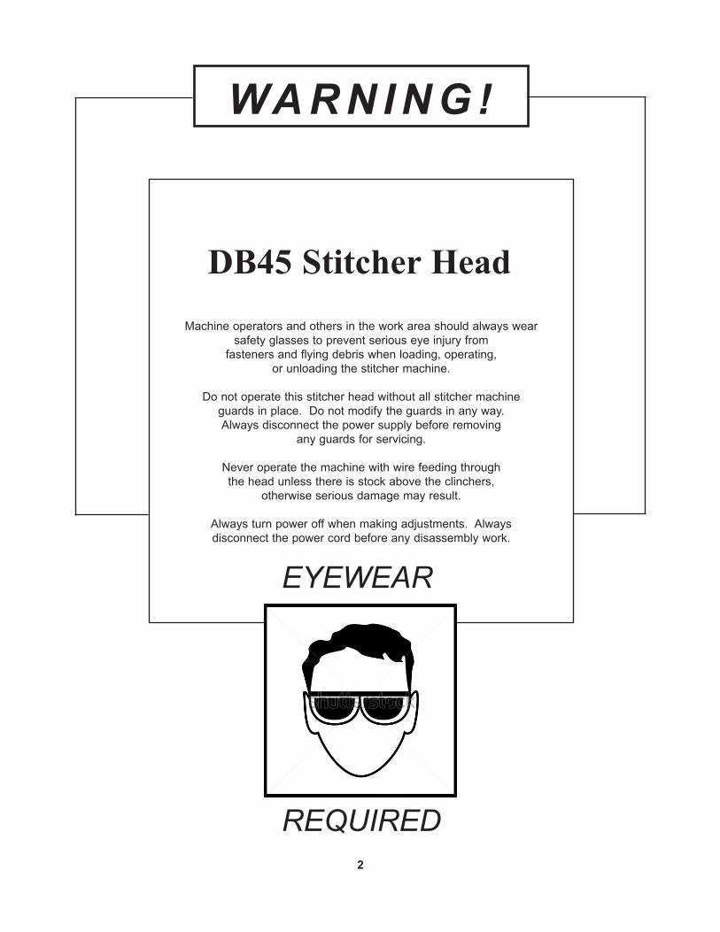
WA R N I N G !
DB45 Stitcher HeadMachine operators and others in the work area should always wear
safety glasses to prevent serious eye injury fromfasteners and flying debris when loading, operating,
or unloading the stitcher machine.
Do not operate this stitcher head without all stitcher machine guards in place. Do not modify the guards in any way.Always disconnect the power supply before removing
any guards for servicing.
Never operate the machine with wire feeding throughthe head unless there is stock above the clinchers,
otherwise serious damage may result.
Always turn power off when making adjustments. Alwaysdisconnect the power cord before any disassembly work.
2
EYEWEAR
REQUIRED

Introduction ........................................................................................................4
Specifications .....................................................................................................5
Installation .......................................................................................................6 Pre-Inspection ................................................................................6 Inspection ......................................................................................6 Mounting ........................................................................................7 Assembly .......................................................................................7
Operation ........................................................................................................9 Wire Threading ..............................................................................9 Wire Straightening ........................................................................10 Adjustments and Settings .............................................................11
Maintenance ......................................................................................................14 Lubrication ....................................................................................15 Cleaning ........................................................................................16 How to Order Spare Parts .............................................................17 Replacing Spare Parts ...................................................................17
Troubleshooting ................................................................................................25
Appendices ......................................................................................................27 Exploded Drawings ........................................................................29 Part Number/Description Cross Reference ..................................41
Notes ......................................................................................................43
Registration Card .............................................................................................44
Wear/Replacement Parts ..............................................................................45
Warranty .......................................................................................................46
Table of Contents
3

The DB45 Stitcher Head is the latest addition to the Company’s product line and the third in a series of DB-Replacement Heads. These heads along with a complete line of fully interchangeable replacement parts are now available for current Muller-Martini* users. Anywhere the HK45 or HK55 are utilized the DeLuxe Stitcher DB45HD can be used.
The DB45HD has a stitching capacity from 2 sheets up to 3mm (.125”), a crown size of 11mm (7/16”) and a minimum center to center distance measuring 45mm (1.75”).
Each DB45 head weighs 4.2 lbs (1.9 kgs.) independently. The packaged shipping weight including the Wire Guide Spring, Clincher Plate Assembly and User manuals is 7.0 lbs. (3.2 kgs.).
Always use a high quality Galvanized Wire so the plating does not peel. Excessive peeling will cause clogging and the premature wear of many components.
Introduction
4*Registered Trade Mark

Weight Shipping Weight . . . . . . . . . . . . . . . . 8.0 lbs (3.7 kg) Stitcher Head . . . . . . . . . . . . . . . . . . . 4.2 lbs (1.9 kg)Physical Dimensions Height . . . . . . . . . . . . . . . . . . . . 9-7/8” (25 cm) Width . . . . . . . . . . . . . . . . . . . . 2-3/16” (55 mm) Depth . . . . . . . . . . . . . . . . . . . . 4-5/16” (10 cm)Stitching Capacity Two Sheets to 1/8” (3 mm)*Wire Types . . . . . . . . . . . . . . . . . . . . 25 through 28 round* Actual stitching thickness capacity depends on the type of stock being stitched and the capacity of the trimmer being used.
Specifications
5
Stitcher Head / Stitcher Machine CompatibilityStitcher Machine Compatible Stitcher Heads
JGV DB75HD DB75VHD DB45HD Loop not recommended. X
Fox, 221, 235 DB75HD DB75VHD DB45HD DB75VHD-LOOP X
331, 335 DB75HD DB75VHD DB45HD DB75VHD-LOOP X
Bravo/Prima(Built before 2004) DB75HD DB75VHD DB45HD DB75VHD-LOOP X
Bravo/Prima(Built 2004 or later) DB75LPHD DB75VLPHD DB45LPHD DB75VLPHD-LOOP X
Valore/Presto(All) DB75MPHD DB75VMPHD DB45MPHD DB75VMPHD-LOOP X
1509/Minuteman(Built before 2004) DB75MMHD DB75VMMHD DB45MMHD DB75VMMHD-LOOP X
1509/Minuteman(Built 2004 or later) DB75MMMPHD DB75VMMMPHD DB45MMMPHD DB75VMMMPHD-LOOP X
301/Optima/Tempo/Supra X X X X DB75VSHD
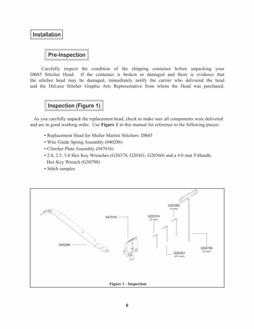
Carefully inspect the condition of the shipping container before unpacking your DB45 Stitcher Head. If the container is broken or damaged and there is evidence that the stitcher head may be damaged, immediately notify the carrier who delivered the head and the DeLuxe Stitcher Graphic Arts Representative from whom the Head was purchased.
Installation
6
Pre-Inspection
As you carefully unpack the replacement head, check to make sure all components were delivered and are in good working order. Use Figure 1 in this manual for reference to the following pieces:
•ReplacementHeadforMullerMartiniStitchers:DB45 •WireGuideSpringAssembly(040286) •ClincherPlateAssembly(047016) •2.0,2.5,3.0HexKeyWrenches(G20374,G20361,G20360)anda4.0mmT-Handle Hex Key Wrench (G50708) •Stitchsamples
Inspection (Figure 1)
Figure 1 - Inspection
040286
047016
G20360(3 mm)
G50708(4 mm)
G20374(2 mm)
G20361(2.5 mm)

Mounting & Assembly (Figure 2)
7
Always disconnect the power before assemblingor making adjustments to your stitcher machine.
!CAUTION!
Completely loosen the Head Mounting Screw (042006) which secures the Mounting Strap (047007) to the back of the DB45 Head. Use Figure 2 for part number reference. Slide the Mounting Strap into the rail of your Müller-Martini* Stitcher Machine. Line up the groove in the Bender Slide Assembly (040162) and the groove in the Driver Slide Assembly (047005) with the grooves in the rails of the Stitcher. Slide the head downward until the key in the Bonnet slips into the groove in the Bonnet Rail just above the Mounting Strap. Secure the Head to the Mounting Strap by tightening the Screw with the supplied 4 mm T-Handle Wrench (G50708).
040286
047007 042006
040162
047005
042003 (2)
Figure 3 - Close-Up
Bonnet Rail
*Registered Trade Mark
Driving Rail
Bending Rail
Figure 2 - Mounting

8
Remove the two (2) Flat Head Cap Screws (042003) from the DB45 Head and line the holes in the Wire Guide Spring Assembly (040286) up with the holes in the Stitcher Head. Secure the Wire Guide Spring with these same Screws.
Secure and align the Clincher Plate Assembly (047016) to the Stitcher Machine by first loosening the two (2) Cheese Head Machine Screws (072012) in the supplied Clincher Plate Assembly until the Clincher Mounting Bar (047014) is free. Slide the Mounting Bar into the rail of the Stitcher Machine and align the Clincher Slide (047002) in the corresponding rail on the Stitcher. Secure the Clincher Plate Assembly to the Mounting Bar by tightening the same two (2) Screws previously loosened. But before completely tightening the Screws, align the Clincher Points (047003), within the Clincher Plate Assembly, directly under the Driver (040152-25). Refer to Figure 4 for part number reference.
Jog the Stitcher machine to make sure the Head has been properly mounted to the Stitcher machine. Once the Machine has been jogged through several cycles, it is safe to test the Head at full speed.
Figure 4 - Aligning Clincher Plate Assembly
047016
047003 (2)
047002
072012 (2)
040152-25
CENTERLINE

Before the Stitcher Machine is turned on, release the Wire Holder Assembly (040543A), secured by the Wire Holder Retaining Spring (040183) by loosening the Screw (042001) on the front of the Head. Thread the wire from the Spool under the studs on the Wire Guide Spring (040286), between the Wire Oiler Felts (G20293) on the Spring and into the Wire Nozzle (070181). Turn the Feed Release Handle (040119) clockwise so that the Small Feed Gear (070112) is disengaged from the Large Feed Gear (040110A).
Continue to push wire through the DB45 Head until the end of the wire passes the Small and Large Feed Gears, enters the top of the Lower Wire Tube (040144) and begins to come out the bottom. Then, using a small screw driver, wedge the wire up until it enters the Fixed Wire Cutter (040020). Engage the Small and Large Feed Gears by turning the Feed Release Handle counter-clockwise. Jog the stitcher machine to verify that the wire has been threaded correctly.
Note: It will take two full cycles for the proper length staple to come out of the Head.
9
Operation
Wire Threading (Figure 5)040286
040183
042001
070112
040110A
040144
040119
070181
Figure 5 - Wire Threading
040543A

10
For Heads Equipped with a Wire Straightener
Watch the feeding of the Wire out of the Cutter Box Assembly (040197BA) to the right of the Moving Cutter (040145B). Notice the direction the Wire is moving. For the Stitcher Head to work at its opti-mum capacity, the wire should be traveling in a straight horizontal direction when exit-ing the Head.
Top-to-Bottom Adjustment Look to the right of the Cutter Box Assembly, as the Wire being fed through the Head. If the Wire is feeding in an upward or downward direction, the optional Wire Straightener Assembly (040206BA) will have to be adjusted by turning the knob (OSK151M-2)
If the wire is feeding in an upward direc-tion, turn knob counterclockwise to slide Wire Straightener Assembly down to com-pensate. Conversely, if the wire is feeding in a downward direction, turn knob clock-wise to slide Assembly up slightly. Allow enough Wire to be fed through the Head so that an accurate assessment can be made. Make sure the ends of each cut piece of Wire are free of burrs, which would negatively affect the driving and clinching of the formed Wire.
Wire Straightening (Figure 6)
Always disconnect the power before assemblingor making adjustments to your stitcher machine.
!CAUTION!
If your DB45 or HK45 doesn't have a 040206BA straightener order 040197BAA KIT to upgrade your headREV. DESCRIPTION ECO # BY DATE
SCALE:
MATERIAL HEAT TREAT FINISH
THIRD ANGLEPROJECTION
MODEL:
SHEET NO:
DESCRIPTION:
MODEL NUMBER
DR'N/DATE
CHK/DATE
APP'D/DATE
BSIZE
PART NUMBER
SEE B.O.M.
Name
DB45
1
CUTTER BOX, DB45 COMPLETE ASSEMBLY
1:1 040197BAA 040197BAA-MANUALREV
PROPRIETARY AND CONFIDENTIALNO PORTION OF THIS DRAWINGMAY BE QUOTED OR REPRODUCEDIN ANY FORM WITHOUT THEEXPRESS WRITTEN PERMISSIONOF DELUXE STITCHER COMPANY, INC.CHICAGO ILLINOIS 60634 U.S.A.
OEM NUMBER
OF
WEIGHT:
1
0.00 = +/-0.10 [.004] ANGULAR: +/- 1/2°0.0 = +/-0.20 [.008] 0 = +/-0.50 [.020] THREADS: CLASS 2
METRIC [INCHES]
TOLERANCES OF PRIMARY UNITS OF MEASURE(UNLESS OTHERWISE SPECIFIED)
DIMENSIONS IN DUAL METRIC & INCHES ( [ ] ) * ALL DIMENSIONS AREFINISHED DIMENSIONS * DO NOT SCALE - WORK TO DIMENSIONS ONLY
040206BA
OSK151M-2
Good
Bad
Bad
Figure 6 - Wire Straightening040197BAA
FULL ASSEMBLY
040145B

Adjusting the Length of the Right Leg (Figure 7)
11
Once the DB45 has been threaded and the wire engaged by the Feed Gears, it is time to begin stitching. Replace the Wire Holder Assembly (040543A) and secure it to the Head with the Wire Holder Retaining Spring (040183). Make sure to tighten the Screw (042001) at the top of the Spring afterwards.
Jog the Stitcher Machine once to load a piece of wire into the Wire Holder Assembly. Even though each DB45 Stitcher Head has been tested at the factory, the wire draw adjusted and the legs equalized, the following are directions to make these adjustments if necessary.
Lengthening the Stitch’s Right Leg If after a few stitches, the length of the stitch’s right leg is too short or too long compared to that of the left, you will need to make adjustments. It is difficult to adjust the length of the left leg alone, so adjustments are always made to the right leg first. To compensate for the length of the left leg, adjust the stitch’s right leg to match the left and then make adjustments for the overall length of the stitch or wire draw.
Power off the Stitcher Machine and release the Extension Spring (074002) from the Feed Gear Operating Lever Pin (043002) on the Replacement Head. Disengage the Small Feed Gear and the Large Feed Gear by turning the Feed Release Handle (040119) clockwise. Push the Feed Gear Operating Lever (047008) down which will move the pin on the Feed Gear Pinion Assembly out of the way of the Feed Gear Stop (047010). Loosen, but do
Figure 7 - Adjusting the Right Leg and Gap
Always disconnect the power before assemblingor making adjustments to your stitcher machine.
!CAUTION!
040543A
040119
040183
074002
043002
042001
longerright leg
shorterright leg
047008
042001
047010
040197BA

12
Always disconnect the power before assemblingor making adjustments to your stitcher machine.
!CAUTION!
not remove, the Screw (042001) securing the Feed Gear Stop (047010) to the top of the Cutter Box Assembly (040197BA). If the right leg of the stitch is too short, slide the Feed Gear Stop to the left slightly. Tighten the Screw (042001) at this point. Replace the Extension Spring and power on the Stitcher Machine. Re-engage the Small and Large Feed Gears and jog the Stitcher to observe the length of the stitch’s right leg after the initial adjustment. Continue to make adjustments and re-test the Head until the length of the stitch’s right leg is satisfactory.
Shortening the Stitch’s Right Leg If the right leg of the stitch is too long, power off the Stitcher machine. Release the Extension Spring (074002) from the Feed Gear Operating Lever Pin (043002). Disengage the Small Feed Gear and the Large Feed Gear by turning the Feed Release Handle (040119). Push the Feed Gear Operating Lever (047008) down which will move the pin on the Feed Gear Pinion Assembly out of the way of the Feed Gear Stop (047010). Loosen, but do not remove the Screw (042001) securing the Feed Gear Stop to the Cutter Box Assembly (040197BA) and slide the Stop slightly to the right. Tighten the Screw at this point to secure this position. Replace the Extension Spring. Re-engage the Small and Large Feed Gears and jog the Stitcher to observe the length of the stitch’s right leg after the initial adjustment. Continue to make adjustments and re-test the Head until the length of the stitch’s right leg is satisfactory.
Increasing the Overall Length of the Stitch (Decreasing the Gap)
To change the overall length of the stitch, or more specifically to change the gap between the legs of the stitch, the position of the Cutter Box Assembly (040197BA) must be adjusted. To increase the overall wire draw or decrease the gap between the legs, first power off the Stitcher Machine and release the Extension Spring (074002) from the Feed Gear Operating Lever Pin (043002) and loosen
Adjusting the Wire Draw / Stitch Gap (Figure 8)
Good Shorten Both Legs Good Shorten Right Leg Lengthen Right Leg
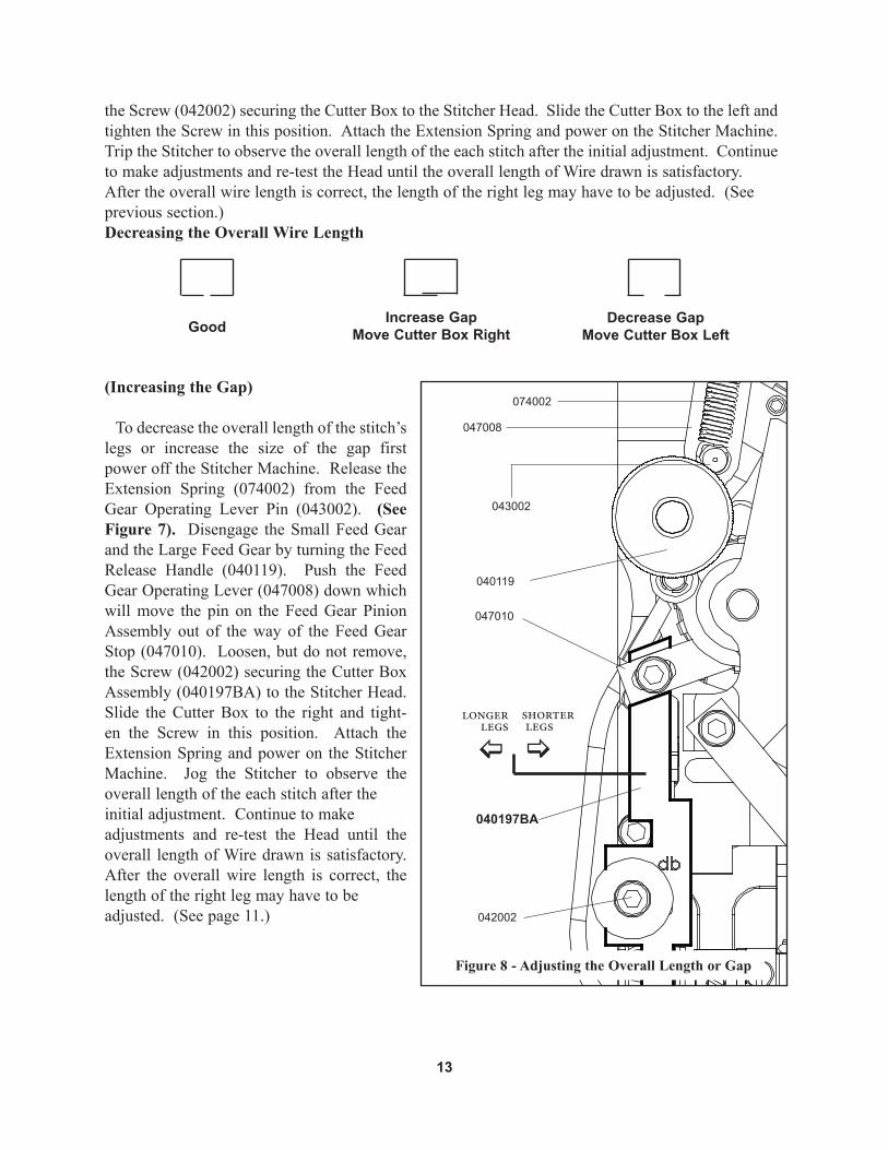
(Increasing the Gap)
To decrease the overall length of the stitch’s legs or increase the size of the gap first power off the Stitcher Machine. Release the Extension Spring (074002) from the Feed Gear Operating Lever Pin (043002). (See Figure 7). Disengage the Small Feed Gear and the Large Feed Gear by turning the Feed Release Handle (040119). Push the Feed Gear Operating Lever (047008) down which will move the pin on the Feed Gear Pinion Assembly out of the way of the Feed Gear Stop (047010). Loosen, but do not remove, the Screw (042002) securing the Cutter Box Assembly (040197BA) to the Stitcher Head. Slide the Cutter Box to the right and tight-en the Screw in this position. Attach the Extension Spring and power on the Stitcher Machine. Jog the Stitcher to observe the overall length of the each stitch after the initial adjustment. Continue to make adjustments and re-test the Head until the overall length of Wire drawn is satisfactory. After the overall wire length is correct, the length of the right leg may have to be adjusted. (See page 11.)
Figure 8 - Adjusting the Overall Length or Gap
13
047010
shorter legs
040197BA
Good Increase GapMove Cutter Box Right
Decrease GapMove Cutter Box Left
the Screw (042002) securing the Cutter Box to the Stitcher Head. Slide the Cutter Box to the left and tighten the Screw in this position. Attach the Extension Spring and power on the Stitcher Machine. Trip the Stitcher to observe the overall length of the each stitch after the initial adjustment. Continue to make adjustments and re-test the Head until the overall length of Wire drawn is satisfactory. After the overall wire length is correct, the length of the right leg may have to be adjusted. (See previous section.)Decreasing the Overall Wire Length
074002
043002
040119
047008
042002
longer legs

Your DB45 Stitcher Heads have been fully lubricated at the factory, but to insure continuous superior operation and a longer life of the heads, the operator should be sure that the heads are lubricated regularly and carefully maintained. The operator should periodically inspect all moving parts for signs of wear and when required, replace the worn parts. Some parts, like the Drivers and Wire Cutters, are subject to high wear and have been designed to be reversible to provide additional surfaces. If the original driving or cutting surfaces of any of these parts show signs of wear, their position in the head can be changed, thereby providing a new surface and lengthen the life of the part. For a complete list of wear and replacement parts for your DB45 style Stitcher Heads, refer to page 43 in the back of this manual.
14
Adjusting the Clincher Points (Figure 9)
If the clinch on the staple is not tight enough, the Clincher Points (047003) have to be raised. Conversely, if the clinch is too tight, the Clincher Points have to be lowered. This adjustment is made on the Stitcher Machine and so cannot be completely explained in this manual as each individual Machine is different. Refer to your saddle machine’s user guide for more information.
The final position of the Clincher Points should be flush (or slightly above flush) with the Clincher Plates (047017 and 047015). The best way to see the position of the Clincher Points is to jog the Machine where the Muller Replacement Head is mounted. When the Driver (040152-25) is at the lowest position of its stroke, the Clincher Points are at their highest position. Jog the Stitcher Machine until the Stitcher Head just past this point to reveal the Clincher Points’ position. To be sure that the Points are at the best position possible, run a few test stitches and compare the clinched staples.
Always disconnect the power before assemblingor making adjustments to your stitcher machine.
!CAUTION!
Figure 9 - Adjusting Clincher Points
047003 (2)
040152-25
Maintenance
047015 and 047017
15
Lubrication (Figure 10)
Use any standard S.A.E. #10 oil for lubricating the heads. Heads that are in constant operation should be lubricated daily. Heads that are operated periodically should be lubricated every five pound wire spool change or every month, which ever comes first. Usually, only a drop of oil is required at each lubrication point. Care must be taken that those parts of the head that contact the work to be stitched are free of oil. Lubricate regularly instead of excessively. Excessive oiling will result in work becoming spotted with oil. Use one drop of oil in the following lubrication points:
•atthetopoftheBonnet(040000)on either side of the Driver Slide (047005) and Bender Slide (040162).
•ontheledgeoftheBenderSlideInsert (077012).
•BetweentheSmallFeedGear(070112) and the Feed Release Cam Assembly (040118).
•inbetweentheWireHolderRetaining Spring (040183) and the Wire Holder Assembly (040543A).
•ontheHookPivotScrew(042005)inthe Wire Holder Assembly (040543A).
•ontheCutterBoxAssembly(040197BA) behind the Cutter Operating Lever (040230).
•oneachoftheClincherPointPivotPins (077018-2) on the Clincher Back Plate (047015)
040118
040162
047005
040183
040543A
040230
070112
Figure 10 - Lubrication and Cleaning

In addition to proper lubrication, routine cleaning is important for the maintenance of your DB45 Heads. The entire Head should be removed, torn down and rebuilt at least every three months and the following areas should be cleaned once every month:
•Feed Gear Assembly: remove the Extension Spring (074002), the Set Collar (077007) and the E-Ring (073001) to release the Feed Gear Operating Lever Assembly (047008). Slide the Driver Slide Assembly (047005) and the Bender Slide Assembly (040162) out the Back of the Bonnet and loosen the Screw securing the Friction Strip (040186). Remove the Feed Gear Assembly and wash in an oil-dissolving solvent, dry and relubricate with a light Bearing Grease; DeLuxe Stitcher recommends Shell Alvania 2.
•Wire Holder (040543A): release the Wire Holder from the Retaining Spring and wash in an oil-dissolving solvent, dry and return the Holder to the Head. Grease the front surface of the Wire Holder, Hook Spring and surface of Hook prior to installation.
• Cutter Box Assembly: loosen and remove the screw securing the Assembly to the Head,
remove the Cutter Operating Slide (040198) and Spring (040210) and wash all three pieces in an oil-dissolving solvent. Dry the pieces thoroughly, grease the Spring and re-assemble the Cutter Box Assembly.
•Anywhere that dust, oil or pieces of wire and paper have built up - for example: in the Clincher Plate and around the Clincher Points.
When rebuilding DB45 Heads, be careful to lubricate high friction areas with a Multipurpose EP Grease. Refer to the exploded drawings on pages 27 - 42 for a detailed description of the areas that need to be greased and the amount of Grease to use.
Cleaning (Figure 11)
16
Figure 11 - Cleaning
040543A 040111A040198
040210
040110A
047016
040197BA
047001

17
In time, you will need to replace some parts in your DB45 Head. When this happens, first locate the necessary part in one of the following diagrams. Then locate the DeLuxe Stitcher part number and contact your Graphic Arts Representative to order the part by the part number, description and quantity.
Ordering Spare Parts
Replacing Spare Parts
The following are some of the more common wear parts which will need to be removed and replaced in your DB45 Head. Most replacements require the Stitcher Head to be removed from the Stitcher Machine and disassembled. These instructions will be given first, then a more specific description for replacing the individual wear parts will follow.
General Maintenanceand Repair (Figure 12)
Cut the wire feeding to the Stitcher Head just below the Wire Spool. Disengage the Small Feed Gear (070112) from the Large Feed Gear (040110A) by turning the Feed Release Handle (040119). Pull the remaining wire upward through the DB45 Head. Loosen and remove the Screw (042006) and Washer (071006) securing the Stitcher Head to the Mounting Strap (047007) and to the Stitcher Machine. Place the DB45 on a clean, flat work area and remove the Wire Guide Spring (040286) by remov-ing the two (2) Screws (042003) secur-
Always disconnect the power cord before any maintenance is done or adjustments are
made to the Müller* Replacement Head
!CAUTION!
*Registered Trade Mark
040119
040183
042003 (2)
070112
040110A
042006
047007
040286
042001, 071006
074002
057002
043002
072010
077007
047005
040162
Figure 12 - Removing & Disassembling the Stitcher Head

18
ing the Spring to the Head. Refer to Figures 3 and 12 for part number reference.
Loosen and remove the Screw (042001) along with the Washer (071006), securing the Wire Holder Spring (040183) to the Bonnet. Failure to do so may cause damage to the Wire Holder Spring. Refer to Figure 12 for part number reference. Remove the Spring from the Head and the Wire Holder Assembly (040543A) from under the Spring Assembly. Disengage the Spring (074002) from the Driver Slide Shaft (057002) and from the Feed Gear Operating Lever Pin (043002). Loosen the Screw (072010) securing the Set Collar (077007) and remove it from the Driver Slide Shaft as well. Once the E-Ring (073001) is removed from the Pin (043003) in the Feed Gear Pinion Assembly ( 040111A), the Feed Gear Operating Lever Assembly (047008) can be removed from the Stitcher Head. Refer to Figure 13 for part number reference.
To remove the Cutter Box Assembly (040197BA) from the DB45 Head, loosen and remove the Screw (042002), the Ribbed Washer (071006) and the Plain Washer (041001) securing the Assembly to the Head. Remove the Driver Slide Assembly (047005) and Bender Slide Assembly (040162) from the Bonnet. And then slide the Driver Slide Assembly out from the Bender Slide Assembly. Refer to Figure 12 for part number reference.
Loosen and remove the Screw (072001) and Ribbed Lock Washer (071005) securing the Friction Strip (040186) to the Bonnet and remove the Feed Gear Assembly (040111A, 047001 and 040110A). Loosen and remove the Feed Cam Plunger Bushing (047018) and take with it the Compression Spring
073001
040111A
047008
040543A
043003
040110A
047001
REV. DESCRIPTION ECO # BY DATE
SCALE:
MATERIAL HEAT TREAT FINISH
THIRD ANGLEPROJECTION
MODEL:
SHEET NO:
DESCRIPTION:
MODEL NUMBER
DR'N/DATE
CHK/DATE
APP'D/DATE
BSIZE
PART NUMBER
SEE B.O.M.
Name
DB45
1
CUTTER BOX, DB45 COMPLETE ASSEMBLY
1:1 040197BAA 040197BAA-MANUALREV
PROPRIETARY AND CONFIDENTIALNO PORTION OF THIS DRAWINGMAY BE QUOTED OR REPRODUCEDIN ANY FORM WITHOUT THEEXPRESS WRITTEN PERMISSIONOF DELUXE STITCHER COMPANY, INC.CHICAGO ILLINOIS 60634 U.S.A.
OEM NUMBER
OF
WEIGHT:
1
0.00 = +/-0.10 [.004] ANGULAR: +/- 1/2°0.0 = +/-0.20 [.008] 0 = +/-0.50 [.020] THREADS: CLASS 2
METRIC [INCHES]
TOLERANCES OF PRIMARY UNITS OF MEASURE(UNLESS OTHERWISE SPECIFIED)
DIMENSIONS IN DUAL METRIC & INCHES ( [ ] ) * ALL DIMENSIONS AREFINISHED DIMENSIONS * DO NOT SCALE - WORK TO DIMENSIONS ONLY
042002
041001
071006
040197BA
Figure 13 - Disassembling the Stitcher Head

(044002) and Feed Cam Plunger (077009) to release the Feed Release Cam Assembly (040118) and Feed Release Handle (040119). Refer to Figure 14 for part number reference.
Removing and Replacing the Cutters (Figure 15)
If burrs appear on the ends of your cut wire or if the wire bends but does not cut, the Moving and or Fixed Cutter may need to be replaced. The position of the Moving Cutter (040145B) on the Cutter Operating Slide (040198) can be rotated several times before the part has to be exchanged for new. Simply loosen the Cutter Mounting Screw (042007) which has a left-handed thread and rotate the Moving Cutter until a fresh cutting edge is lined up with the Fixed Cutter (040020). Tighten the Screw at this point to secure the position.
The Fixed Cutter can also be rotated when worn by loosening the Set Screw (G20191) and rotating the position of the Cutter within the Cutter Box Assembly (040197BA). The Fixed Cutter has to be
lined up again with the Moving Cutter before the Screw can be tightened. The Screw also should be treated with a Threadlocker before tightened down on a new or rotated Fixed Cutter. Insert the Cutter Operating Slide back into the Cutter Box and make sure there is free movement between the Cutter Box and the Cutter Operating Slide when both Cutters are as close as possible to each other. If there is free movement, tighten the Screw securing the Fixed Cutter. If the Cutter Operating Slide does not slide freely within the Cutter Box, move the Fixed Cutter back into the Cutter Box slightly until free movement is re-established and then tighten the Screw at this point.
Note: Too much gap between the Cutters will cause premature wear on both parts as well as severe burrs on the ends of each piece of cut wire.Removing and Replacing the Cutter Operating Slide (Figure 16)
Once the Cutter Box Assembly has been removed from the Stitcher Head, the Cutter Operating Slide
19
Figure 14 - Stitcher Head Disassembly
071005
047018
040119
Figure 15 - Replacing the Cutters
040198
042007
040145B
040020G20191
040197BA
040110A
047001
040111A
044002077009
072001
040118
040186
(040198) can be replaced easily. Wire that is not cut, gets an incomplete cut or has large burrs on its ends may be the result of a worn Cutter Operating Slide. Remove the Operating Slide from the Cutter Box, being careful of the Cutter Operating Spring (040210). If the Moving Cutter does not have to be replaced at this time, it will have to be removed from the Operating Slide. The Cutter Mounting Screw (042007), securing the Cutter, has a left-handed thread and must be loosened clockwise. Replace the worn Cutter Operating Slide and secure the existing or new Cutter to the Slide with the Screw, turning counter-clockwise. Be sure to mount the Moving Cutter securely to the Operating Slide. A loose fit adversely affects the cut and drive of the wire. Roll the Cutter Box Spring in Red E-Lube Grease and insert it in the slot of the Cutter Box. Compress the Spring with the end of the Cutter Operating Slide as you insert it back into the Cutter Box. The assembly can be secured to the Head again with the Cap Screw (042002), Ribbed Lock Washer (071006) and the plain Large Washer (041001).
Replacing the Hook Pivot Pin (Figure 17)
The Wire Holder Hook Assembly (047013A) pivots on the Hook Pivot Pin (042005) with every stroke of the Stitcher Head. When the Pivot Pin is worn, wire may drop out of the Wire Holder Assembly (040543A) or the Hook may begin to block the entry of the wire as it is fed. Replacing the Hook Pivot Pin when worn will prevent this from happening. Release the Extension Spring (074001) from the Wire Holder Hook Assembly. Unscrew the worn Hook Pivot Pin, releasing the Hook Assembly and replace it with a new Pivot Pin. make sure the new Pin has a Nylon patch on its threads or treat it with a threadlocker. Re-attach the Extension Spring to the Wire Holder Hook Assembly and grease the outside of the Extension Spring with Red E-Lube Grease. The Wire Holder Assembly can now be replaced under the Wire Holder Spring.Replacing the Clincher Points (Figure 18)
Figure 16 - Replacing the Cutter Operating Slide
040198
Figure 17 - Replacing the Hook Pivot Pin
042005
040543
047013A
074001
042007
040210
042002
041001
071006
20

21
If the legs of the staple are not completely clinched even though the Clincher Points (047003) are properly adjusted or if the legs of the staple “wander” from stitch to stitch, the Clincher Points or Clincher Slide Assembly may need to be replaced. Loosen and remove the two (2) Screws (072012) and Ribbed Lock Washers (071003), securing the Clincher Front Plate (047017). Release the Clincher Slide Assembly (047002) which in turn unlocks the Clincher Points. Remove the worn Points from the Clincher Point Pivots (077018-2) and replace them. Insert the existing or new Clincher Slide Assembly within the Clincher Back Plate (047015), between the two Points. Secure the Clincher Front Plate to the rest of the assembly with the two Screws.
Replacing the Driver (Figure 19)
If the rib of the Driver (040152-25) is worn or even chipped, the crown of the staples pro-
duced could be buckled or the corners may be sheared. The Driver on the DB45 Head is reverseable so that when one edge is worn or damaged, it can be reversed to extend the life of the part. Simply remove the Driver from the Driver retaining Screws (072015) and reverse its position. If both sides are worn or one of the ribs is severely broken, replace the old Driver with a new one. Secure the new Driver to the Driver Slide Assembly with the exist-ing Screws after treating them with a threadlocker.
Replacing the Formers (Figure 20)
Over time, both the Right and Left-Hand Formers (040548-25 and 070548L-25) will wear with use. When this occurs the wire passing through the Formers could become distorted and not drive properly. Once the Bender Slide Assembly (040162) has been removed from the Head, replacing worn Formers is a simple task.
Loosen and remove the two (2) Screws (072011) as well as the two (2) Ribbed Lock Washers (071005) securing the Left-Hand Former to the Bender Slide Assembly. Loosen and remove the Screw (072011)
Figure 18 - Replacing the Points and Slide
047015
047002
047003 (2)
Figure 19 - Replacing the Driver
040152-25
047005
077018-2 (2)
072012 (2)
071003 (2)
072015 (2)
047017

22
and Ribbed Washer (071005) securing the bottom half of the Right-Hand Former and the Screw (OSK127-1) securing the Hook Guide (047012) and top half of the Right-Hand Former to Bender Slide Assembly. The Centering Guide (047004), Centering Guide Post (047006), Centering Guide Spring (044001) and Shim Ring (071002) will have to be removed and transferred to the new Former before re-assembly can begin. Straighten the Cotter Pin (073003) and slip it out of the Centering Guide Post to release the Centering Guide Assembly. Insert the existing Centering Guide, the Post, and the Spring into the new Right-Hand Former. Top the Guide Post with the Shim Ring and secure the whole assembly with a new Cotter Pin. Next, exchange the old Left-Hand Former for the new one and replace it with the Screws and Washers removed previously. Make sure to treat the Screws with a threadlocker before inserting them into the
Head. Similarly, secure the new Right-Hand Former using the old Screws and Washers. Be sure to replace the Hook Guide along with the Right-Hand Former and treat the Screws with a threadlocker.
Replacing the Hook Guide (Figure 20)
When continued use wears or damages the Hook Guide (047012), it can be easily exchanged for new by removing the Screw (OSK127-1) securing it. When the Hook Guide wears or breaks, the Wire Holder Hook Assembly in the Wire Holder is not activated with each stroke of the Head. If this occurs, no wire will be allowed into the Wire Holder to be formed or driven. Be sure to use a thread-locker on the Screws when replacing the Hook Guides to the Right-Hand Formers.
Re-assembling the Stitcher Head (Figure 21)
After all cleaning and lubrication is complete and any spare parts that have been added are secure, the DB45 Head is ready to be re-assembled. Refer to the exploded drawings on pages 27 - 42 for a detailed description of the areas that need to be greased and the amount of Grease to use.
1. Slip the Feed Gear Assembly over the Feed Gear Shaft (040114). Make sure it is pressed flush against the Bonnet (040000). The Pin (043003) on the Feed Gear Pinion Assembly (040111A) should be positioned just right of the Feed Release Handle (040119). (See figure 21)
2. Grease the front of the Driver Slide Assembly (040162) and slip it between the Formers on the Bender Slide Assembly (047005), after greasing the front of it. Insert both parts into the slot on the
Figure 20 - Replacing the Formers
040548-25
070548L-25
040162
071002
047012
OSK127-1071005 (4)
072011 (3)
073003
044001
047006
047004
G20273

23
back of the Bonnet (040000). Make sure that the Driver Slide Assembly still moves freely in between the Bender Slide Assembly.
3. Secure the position of the Large Feed Gear (040110A) with a Friction Strip (040186), held in place with Screw (072001) through a Ribbed Lock Washer (071005). Secure the Mounting Strap (047007) to the back of the Bonnet with the Mounting Screw (042006) through a Lock Washer (071006).
4. Slip the Feed Gear Operating Lever Assembly (047008) over the Pin (043003) on the Feed Gear Pinion Assembly and over the Driver Slide Shaft (057002) which has been greased. Secure the Set Collar (077007) to the Shaft with a Screw (072010) and secure the Feed Gear Operating Lever Assembly to the Feed Gear Pinion Assembly with an E-Ring (073001). There should be approximately a 0.04” (1mm) gap between the Set Collar and the Feed Gear Operating Lever.
040000
040111A,INCLUDE 043003
040119
040162
047005
040110A
047008
043003
057002
077007
072010
040197BA
041001
042002
071006040543
040183
042001
040286
Figure 21 - Re-Assembling the Stitcher Head

24
5. Grease the top of the Cutter Operating Slide (040198). Secure the Cutter Box (040198) to the Bonnet (040000) with a Screw (042002) through one (1) Ribbed Lock Washer (071006) and one Washer (041001).
6. Secure the Wire Holder Assembly (040543) under the Wire Holder Retaining Spring (040183) and tighten the Screw (042001).
7. Secure the Wire Guide Spring (040286) to the Bonnet (040000) with two (2) Screws (042003).
Figure 22 - Feed Gear Pinion Asy
Free
whe
el g
Transmit Torque

Troubleshooting (Figure 22)
The quality and quantity of work that can be produced with the DB45 Head is dependent upon the operator making all adjustments as accurately as possible and carefully maintaining the head. The cause of staple imperfections usually can be traced to inaccurate settings or normal wear of moving parts. In the event of trouble of this nature occurring, the operator can, by referring to the following troubleshooting chart, quickly locate and remedy the cause or causes of the trouble.
The following is a brief list of problems and solutions which should cover the majority of situations encountered when stitching with the DB45 Stitching Heads.
25
Figure 23 - Troubleshooting
problem: Right Leg Shortsolution: Move the Feed Gear Stop to the left, slightly. (See pages 11 - 12)
problem: Right leg Longsolution: Move the Feed Gear Stop to the right and the Cutter Box to the left, slightly. (See pages 11 - 12)
problem: Corner Buckledsolution: Check the Driver for a chipped corner and rotate or replace it if needed. (See page 21) Use a heavier gauge wire.
problem: Leg(s) Buckledsolution: Check the Wire Cutters and Wire Cutter Operating Slide for wear and rotate or replace if needed. (See pages 19 - 20) Use a heavier gauge wire. Make sure the Clincher Plate is aligned with the Head.
Always disconnect the power cord before any maintenance is done or adjustments are
made to the Muller Replacement Head
!CAUTION!

problem: Crown Buckledsolution: Check to make sure the Driver is not damaged; reverse or replace if necessary. Verify that the Formers are not worn; replace if need be. (See page 21). Use a heavier gauge wire.
problem: Stitch in Piecessolution: Clean and lubricate the Head (See page 15 - 16) Check for hard or brittle wire and replace. Check the tension of the Wire Holder Spring and replace Spring if too loose. Look for wear in Wire Holder pivot point in Bonnet.
problem: Loose Clinchsolution: Raise the Clincher Points. (See page 14)
problem: Legs are Spread or Contractedsolution: Check the Wire Cutters for wear and rotate or replace if needed. (See pages 19 - 20) Check the Formers for wear in the grooves and replace if needed. Use a heavier gauge wire.
problem: Wire jam near Feed Gearsolution: Cutters may be too tight. Check for the following worn parts and replace if necessary. Fixed Cutter, Moving Cutter, Cutter Operating Slide, Cutter Operating Lever, Bender Slide Insert, Wire Guide, Hook, Hook Pivot Pin, Feed Gear Friction Strip and Wire Holder. There may be debris in the Wire Holder or the Clutch may not be working properly. Oil the Oiler Felt on the Wire Guide Spring.
26
Figure 23 - Troubleshooting
27
Bonnet and Wire Guide SpringSub-Assemblies
042003 (2)
044002
047018
040118
040286G20297
G20292 (2)
G20293 (2)
G20287
G20298
077009
070181
042004
040000
073002
040119
041002070112
grease
grease
Apply lightoil daily
Apply lightoil daily
070720
070722
G20290071006
G40402
PARTS USED FORMULLER MINUTEMANSTITCHERS
28
Bonnet and Wire Guide Spring Sub-Assemblies
DeLuxe Replaces PART No. Muller No. DESCRIPTION QUANTITY
G20287 Wire Oiler Felt Spring 1 G20292 Wire Oil Felt Washer 2 G20293 Wire Oiler Felt 2 G20297 Screw M6x1.0x40 1 G20298 Nylock Lock Nut, M6x1 1 040000 0305.2037.1 Bonnet 1 040118 0305.2022.4 Feed Release Cam Assembly 1 040119 0031.0307 Feed Release Handle 1 040286 0305.2024.4 Wire Guide Spring Assembly 1 041002 0031.0158 Hex Head Jam Nut 1 042003 0030.1016 Screw M5x.8x8 2 042004 0030.1715 Screw M5x.8x10 1 044002 0354.1041.4 Feed Cam Compression Spring 1 047018 0881.0366.4 Feed Cam Plunger Bushing 1 070112 0881.0003.4 Small Feed Gear 1 070181 0881.0009.4 Upper Wire Tube 1 073002 0031.0759 E-Ring 1 077009 0881.0032.4 Feed Cam Plunger 1
070720 1509.1352.3 Wire Guide Tube 1 070722 Tube Clamp, DB45 1 071006 0031.5105 Lock Washer Ribbed M5 2 G20290 Flat Washer M5 2 G40402 Screw M5 x 16mm 2
29
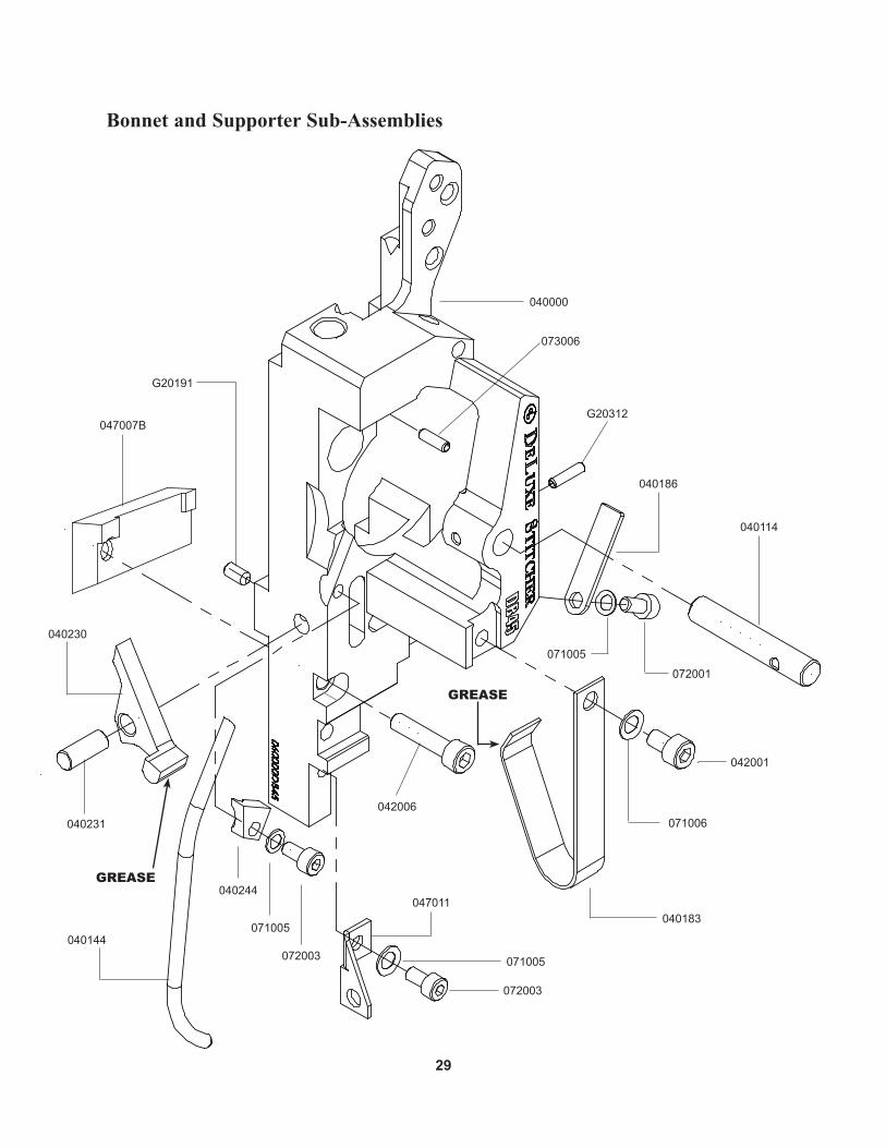
Bonnet and Supporter Sub-Assemblies
047007B
040114
040183
G20191
047011
071005
072003
042006071006
042001
G20312
040186
072001
071005
040144
040231
040230
072003
071005
040244
040000
grease
grease
073006
30
Bonnet and Supporter Sub-Assemblies
DeLuxe Replaces PART No. Muller No. DESCRIPTION QUANTITY
G20191 Screw M4x.7x8 1 G20589 Screw M4x.7x10 1 040000 0305.2037.1 Bonnet 1 040114 0305.2034.4 Feed Gear Shaft 1 040144 0305.2018.4 Lower Wire Tube 1 040183 0882.0079.4 Wire Holder Spring 1 040186 0305.2052.4 Friction Strip 1 040244 0305.2004.4 Wire Tube Clamp 1 040230 0305.2028.4 Cutter Operating Lever 1 040231 0305.2027.4 Cutter Operating Lever Pivot Pin 1 042001 0030.0030 Screw M5x.8x8 1 042006 0305.2047.4 Head Mounting Screw 1 047007B 0305.2021.4 Mounting Strap 1 047011 0305.2040.4 Lower Wire Tube Holder 1 071005 0031.5104 Lock Washer Ribbed M4 3 071006 0031.5105 Lock Washer Ribbed M5 1 072001 0030.0016 Screw M4x0.7x8 1 072003 Screw M4x0.7x12 2 G20312 Spirol Pin M3x12 1 073006 0031.6312 Spring Pin M3x12 1

31
Driver and Bender Inserts
grease
040162
047005057002
077007
072010
040152-25
072015 (2)
OSK127-1
047012
047006
G20273
073008
077012
071005 (2)
047004
072011 (2)
044001
072011
071005
040548-25
071002
073003
grease
grease
grease
grease
grease
071005

32
Drivers and Bender Inserts
DeLuxe Replaces PART No. Muller No. DESCRIPTION QUANTITY
G20273 Screw M4x.7x4, with Nylon Patch 1 OSK127-1 Screw M4x0.7x16 1 040152-25 0305.2019.4 Driver - .6MM 1 040162 0305.2008.3 Bender Slide Assembly 1 040548-25 0305.2014.4 Former RH 25-28 Wire 1 044001 0305.2046.4 Centering Guide Spring 1 047004 0305.2006.4 Centering Guide 1 047005 0305.2009.3 Driver Slide Assembly 1 047006 0305.2016.4 Centering Guide Post 1 047012 0305.2041.4 Hook Guide 1 057002 0882.0019.4 Driver Slide Shaft 1 070548L-25 0881.0016.4 Former LH 25-28 Wire 1 071002 0023.0931 Shim Washer 1 071005 0031.5104 Lock Washer Ribbed M4 4 072010 0030.3447 Screw M4x0.7x5 1 072011 0030.3451 Screw M4x.7x12 3 072015 0249.1054.4 Driver Retaining Screw 2 073003 0031.5021 Cotter Pin 1 073008 0031.9106 Rivet 1 077007 0881.0022.4 Set Collar 1 077012 0881.0040.4 Bender Slide Insert 1
33
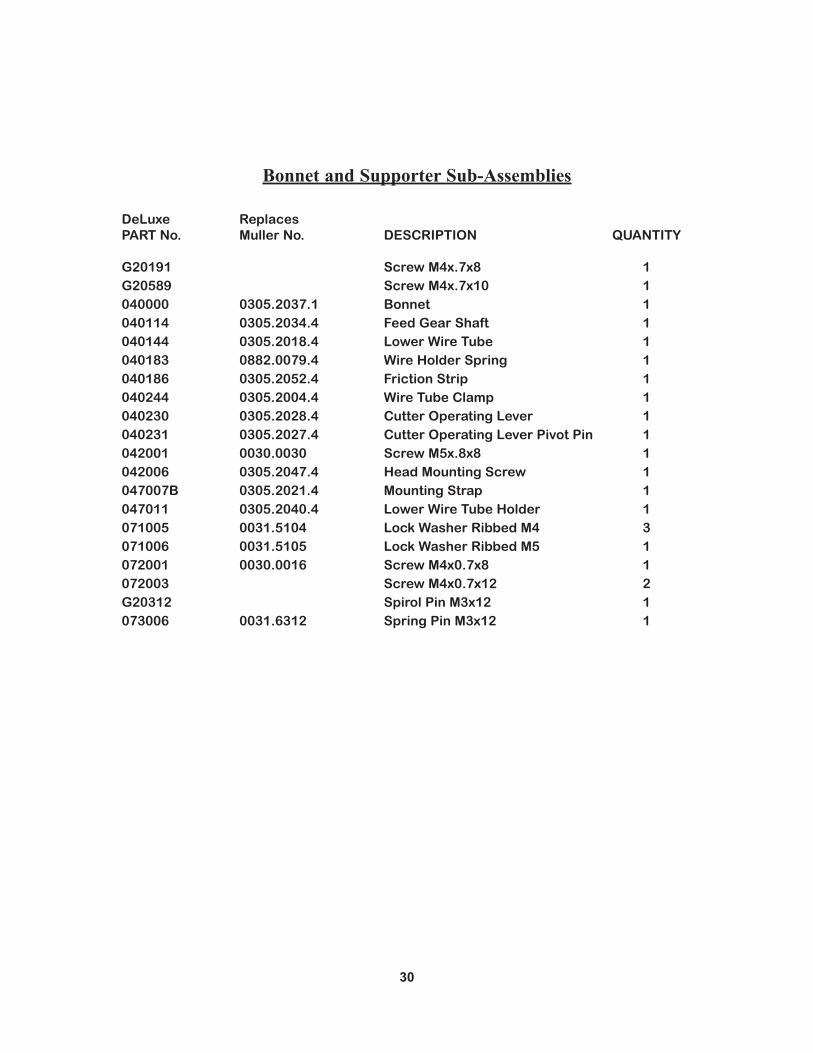
Complete Cutter Box Assembly - 040197BAA
*
**
*
indicate parts not includedin 040197BAA assembly
REV. DESCRIPTION ECO # BY DATE
SCALE:
MATERIAL HEAT TREAT FINISH
THIRD ANGLEPROJECTION
MODEL:
SHEET NO:
DESCRIPTION:
MODEL NUMBER
DR'N/DATE
CHK/DATE
APP'D/DATE
BSIZE
PART NUMBER
SEE B.O.M.
Name
DB45
1
CUTTER BOX, DB45 COMPLETE ASSEMBLY
1:1 040197BAA 040197BAA-MANUALREV
PROPRIETARY AND CONFIDENTIALNO PORTION OF THIS DRAWINGMAY BE QUOTED OR REPRODUCEDIN ANY FORM WITHOUT THEEXPRESS WRITTEN PERMISSIONOF DELUXE STITCHER COMPANY, INC.CHICAGO ILLINOIS 60634 U.S.A.
OEM NUMBER
OF
WEIGHT:
1
0.00 = +/-0.10 [.004] ANGULAR: +/- 1/2°0.0 = +/-0.20 [.008] 0 = +/-0.50 [.020] THREADS: CLASS 2
METRIC [INCHES]
TOLERANCES OF PRIMARY UNITS OF MEASURE(UNLESS OTHERWISE SPECIFIED)
DIMENSIONS IN DUAL METRIC & INCHES ( [ ] ) * ALL DIMENSIONS AREFINISHED DIMENSIONS * DO NOT SCALE - WORK TO DIMENSIONS ONLY
Washer Arrangement.
040210
042002071006
042001
041001
040197BA071006 047010
042007040020
040198
040145B
G50243(INCLUDED WITH
040197BA)
G20191
grease
G20213
040206BA
G20219 (4)
OSK151M-2

34
Cutter Box Assembly
DeLuxe Replaces PART No. Muller No. DESCRIPTION QUANTITY
G20191 Screw M4x.7x8 1 G20213 E-Ring, 1/8" 1 G20219 Disk Spring M4 4 G50243 0031.6025 Spring Pin M4 x 14 1 OSK151M-2 Wire Straightener Knob 1 040020 0882.0058.4 Fixed Cutter 1 040145B 0881.0025.4 Moving Cutter - Steel 1 040197BA 0305.2029.3 Cutter Box Assembly 1 040198 0305.2007.4 Cutter Operating Slide 1 040206BA Wire Straightener Assembly 1 040210 0305.2045.4 Cutter Operating Spring 1 041001 0022.0042 Large Washer 1 042001 0030.0030 Screw M5x.8x8 1 042002 0030.0527 Screw M5x.8x35 1 042007 0305.2048.4 Cutter Mounting Screw 1 047010 0305.2032.4 Limit Stop 1 071006 0031.5105 Lock Washer Ribbed M5 2
35
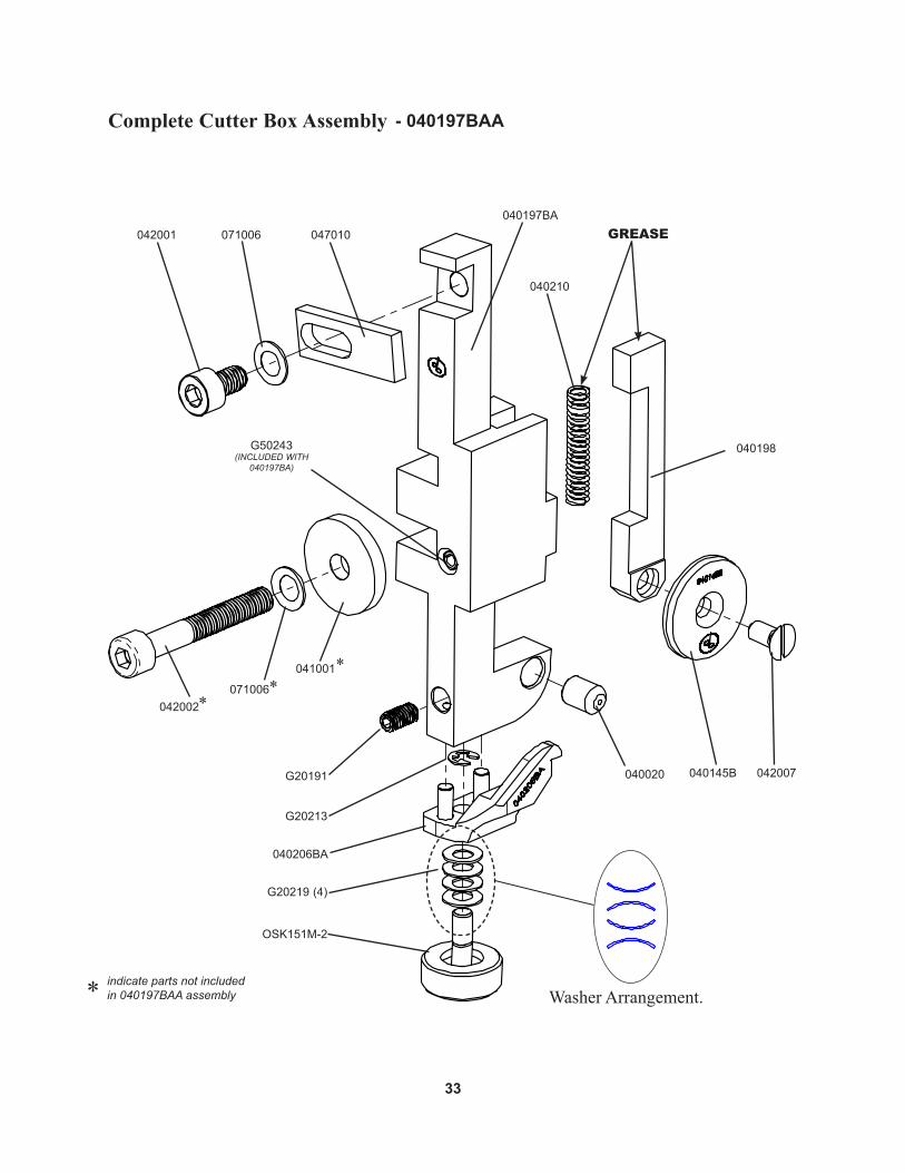
Feed Gear Assembly
047001
047008
040110A
040111A
074002
073001
043002
grease
Apply Shell Alvania 2
Grease
Apply Shell Alvania 2
Grease

36
Feed Gear Assembly
DeLuxe Replaces PART No. Muller No. DESCRIPTION QUANTITY
040110A 0305.2001.4 Large Feed Gear 1 040111A 0305.2031.4 Feed Gear Pinion Assembly 1 043002 0031.6491 Grooved Pin 1 047001 0039.5121 Clutch Bearing 1 047008 0305.2030.4 Feed Lever Assembly 1 073001 0031.0757 E-Ring 1 074002 0034.0302 Extension Spring 1

37
Wire Holder Assembly
047013A
040543
072008042005
074001
grease
grease
grease
grease
grease
- 040543A
38
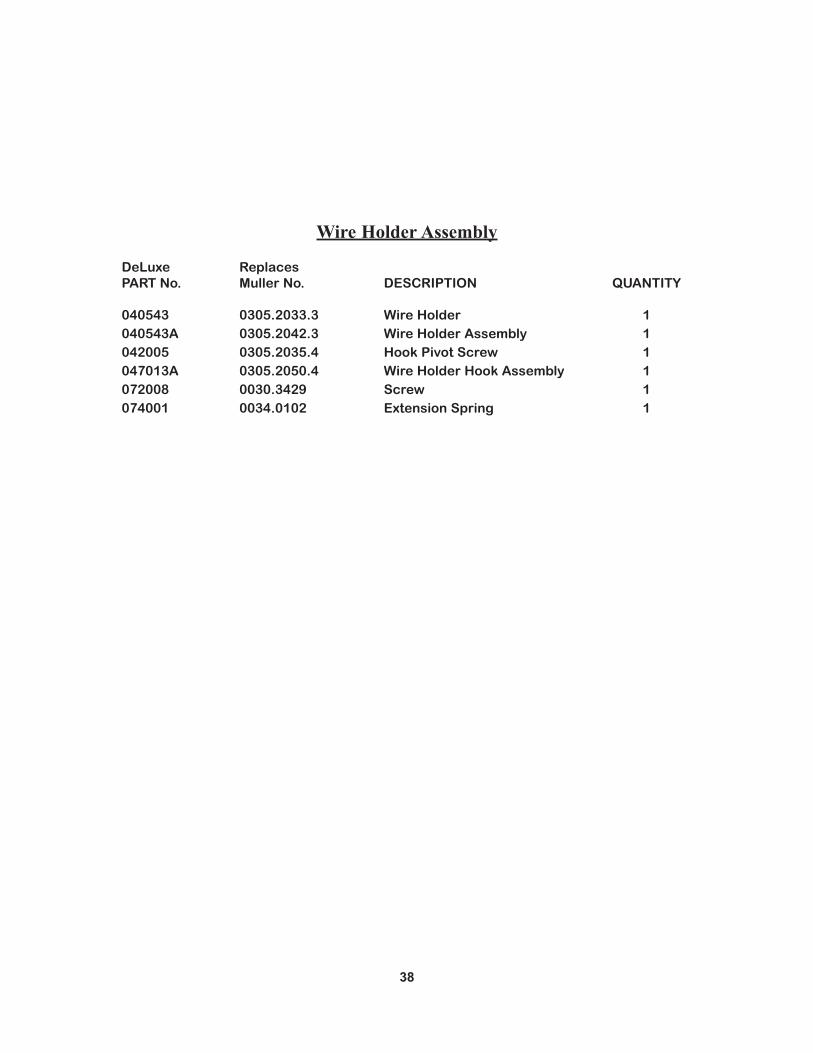
Wire Holder Assembly
DeLuxe Replaces PART No. Muller No. DESCRIPTION QUANTITY
040543 0305.2033.3 Wire Holder 1 040543A 0305.2042.3 Wire Holder Assembly 1 042005 0305.2035.4 Hook Pivot Screw 1 047013A 0305.2050.4 Wire Holder Hook Assembly 1 072008 0030.3429 Screw 1 074001 0034.0102 Extension Spring 1

39
Clincher Plate Assembly
070830ALong Clincher PlateComplete Assembly
070850AMedium Clincher PlateComplete Assembly
047016Standard Clincher PlateComplete Assembly
077015 (2)
070851(INCLUDES 077018-2)
072013 (2)
070853070855
070852
070857 (2)
G20520 (2)
077015 (2)
070831(INCLUDES 077018-2)
072020 (2)
070833
070835
070832
072021 (2)
G20520 (4)
047019B
047019B
*(When using solid clincher platesremove moveable slide & points.)
*
*
*
(Optional Solid Clincher)047019
072012 (2)
047017
G20520 (2)
047003 (2)
047015(INCLUDES 077018-2)
047002
047014
(Optional Solid Clincher)
(Optional Solid Clincher)
"Safety Stitch"
"Safety Stitch"
"Safety Stitch"
40
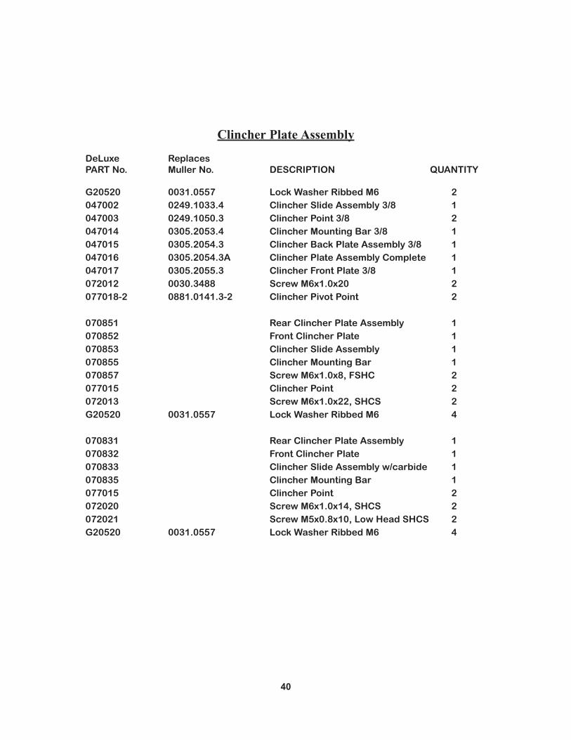
Clincher Plate Assembly
DeLuxe Replaces PART No. Muller No. DESCRIPTION QUANTITY
G20520 0031.0557 Lock Washer Ribbed M6 2 047002 0249.1033.4 Clincher Slide Assembly 3/8 1 047003 0249.1050.3 Clincher Point 3/8 2 047014 0305.2053.4 Clincher Mounting Bar 3/8 1 047015 0305.2054.3 Clincher Back Plate Assembly 3/8 1 047016 0305.2054.3A Clincher Plate Assembly Complete 1 047017 0305.2055.3 Clincher Front Plate 3/8 1 072012 0030.3488 Screw M6x1.0x20 2 077018-2 0881.0141.3-2 Clincher Pivot Point 2
070851 Rear Clincher Plate Assembly 1 070852 Front Clincher Plate 1 070853 Clincher Slide Assembly 1 070855 Clincher Mounting Bar 1 070857 Screw M6x1.0x8, FSHC 2 077015 Clincher Point 2 072013 Screw M6x1.0x22, SHCS 2 G20520 0031.0557 Lock Washer Ribbed M6 4
070831 Rear Clincher Plate Assembly 1 070832 Front Clincher Plate 1 070833 Clincher Slide Assembly w/carbide 1 070835 Clincher Mounting Bar 1 077015 Clincher Point 2 072020 Screw M6x1.0x14, SHCS 2 072021 Screw M5x0.8x10, Low Head SHCS 2 G20520 0031.0557 Lock Washer Ribbed M6 4
41
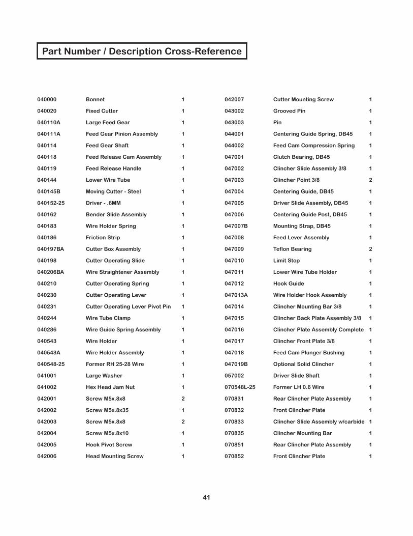
Part Number / Description Cross-Reference
040000 Bonnet 1
040020 Fixed Cutter 1
040110A Large Feed Gear 1
040111A Feed Gear Pinion Assembly 1
040114 Feed Gear Shaft 1
040118 Feed Release Cam Assembly 1
040119 Feed Release Handle 1
040144 Lower Wire Tube 1
040145B Moving Cutter - Steel 1
040152-25 Driver - .6MM 1
040162 Bender Slide Assembly 1
040183 Wire Holder Spring 1
040186 Friction Strip 1
040197BA Cutter Box Assembly 1
040198 Cutter Operating Slide 1
040206BA Wire Straightener Assembly 1
040210 Cutter Operating Spring 1
040230 Cutter Operating Lever 1
040231 Cutter Operating Lever Pivot Pin 1
040244 Wire Tube Clamp 1
040286 Wire Guide Spring Assembly 1
040543 Wire Holder 1
040543A Wire Holder Assembly 1
040548-25 Former RH 25-28 Wire 1
041001 Large Washer 1
041002 Hex Head Jam Nut 1
042001 Screw M5x.8x8 2
042002 Screw M5x.8x35 1
042003 Screw M5x.8x8 2
042004 Screw M5x.8x10 1
042005 Hook Pivot Screw 1
042006 Head Mounting Screw 1
042007 Cutter Mounting Screw 1
043002 Grooved Pin 1
043003 Pin 1
044001 Centering Guide Spring, DB45 1
044002 Feed Cam Compression Spring 1
047001 Clutch Bearing, DB45 1
047002 Clincher Slide Assembly 3/8 1
047003 Clincher Point 3/8 2
047004 Centering Guide, DB45 1
047005 Driver Slide Assembly, DB45 1
047006 Centering Guide Post, DB45 1
047007B Mounting Strap, DB45 1
047008 Feed Lever Assembly 1
047009 Teflon Bearing 2
047010 Limit Stop 1
047011 Lower Wire Tube Holder 1
047012 Hook Guide 1
047013A Wire Holder Hook Assembly 1
047014 Clincher Mounting Bar 3/8 1
047015 Clincher Back Plate Assembly 3/8 1
047016 Clincher Plate Assembly Complete 1
047017 Clincher Front Plate 3/8 1
047018 Feed Cam Plunger Bushing 1
047019B Optional Solid Clincher 1
057002 Driver Slide Shaft 1
070548L-25 Former LH 0.6 Wire 1
070831 Rear Clincher Plate Assembly 1
070832 Front Clincher Plate 1
070833 Clincher Slide Assembly w/carbide 1
070835 Clincher Mounting Bar 1
070851 Rear Clincher Plate Assembly 1
070852 Front Clincher Plate 1

42
Part Number / Description Cross-Reference
070853 Clincher Slide Assembly 1
070855 Clincher Mounting Bar 1
070857 Screw M6x1.0x8, FSHC 2
070112 Small Feed Gear 1
070181 Upper Wire Tube 1
070720 Wire Guide Tube 1
070722 Tube Clamp 1
071002 Shim Washer 1
071005 Lock Washer Ribbed M4 7
071006 Lock Washer Ribbed M5 3
072001 Screw M4x0.7x8 1
072003 Screw M4x0.7x12 2
072008 Screw M3x0.5x3 1
072010 Screw M4x0.7x5 1
072011 Screw M4x.7x12 3
072012 Screw M6x1.0x20 2
072013 Screw M6x1.0x22 2
072015 Driver Retaining Screw 2
072020 Screw M6x1.0x14 2
072021 Screw M5x0.8x10, Low Head 2
073001 E-Ring 1
073002 E-Ring 1
073003 Cotter Pin 1
073006 Spring Pin M3x12 1
073008 Rivet 1
074001 Wire Holder Spring 1
074002 Extension Spring 1
077007 Set Collar 1
077009 Feed Cam Plunger 1
077012 Bender Slide Insert 1
077015 Clincher Point 2
077018-2 Clincher Pivot Point 2
G20191 Screw M4x.7x8 2
G20213 E-Ring, 1/8" 1
G20219 Disk Spring M4 4
G20273 Screw M4x.7x4, with Nylon Patch 1
G20287 Wire Oiler Felt Spring 1
G20290 Flat Washer M5 1
G20292 Wire Oil Felt Washer 2
G20293 Wire Oiler Felt 2
G20297 Screw M6x1.0x40 1
G20298 Nylock Lock Nut, M6x1 1
G20312 Spirol Pin M3x12 1
G20360 Hex Key Wrench 3.0mm 1
G20361 Hex Key Wrench 2.5mm 1
G20374 Hex Key Wrench 2.0mm 1
G20520 Lock Washer Ribbed M6 2
G20589 Screw M4x.7x10 1
G40402 Screw M5x0.8x16 1
G50243 Spring Pin, M4 X 14 1
G50708 T-Handle Hex Key Wrench 1
OSK127-1 Hook Guide Mounting Screw 1
OSK131M-MATL Feed Gear Pinion 1
OSK151M-2 Wire Straightener Knob 1

43
Notes:

RE
GIS
TR
AT
ION
To b
ette
r ser
vice
you
r wire
stit
chin
g ne
eds,
ple
ase
take
a m
omen
t to
fill o
ut a
nd re
turn
this
regi
stra
tion
card
.
Nam
e :
( F
irst )
( M
iddl
e In
itial )
( L
ast )
Com
pany
:
Stre
et A
ddre
ss :
City
:
Stat
e/Pr
ovin
ce :
Zi
p :
Coun
try
:
Phon
e :
Fax
: E-
mai
l :
Mac
hine
(s) P
urch
ased
:
Seria
l Num
ber(
s) :
With
Hea
d(s)
:
( T
ype/
Qua
ntity
Pur
chas
ed )
Seria
l Num
ber(
s) :
Hea
d(s)
Pur
chas
ed :
Seria
l Num
ber(
s) :
Dat
e Re
ceiv
ed :
Dea
ler N
ame
:
Dea
ler S
tree
t Add
ress
:
City
:
Stat
e/Pr
ovin
ce :
Zip
:
Coun
try
:
Dea
ler P
hone
:
Oth
er B
inde
ry P
rodu
cts
Use
d :
Wou
ld y
ou li
ke in
form
atio
n se
nt to
you
abo
ut n
ew p
rodu
cts
that
wou
ld b
enef
it yo
ur c
ompa
ny?
Y
es
No
Ple
ase
take
a m
omen
t to
fill o
ut th
e at
tach
ed c
ard
and
mai
l it t
o D
eLux
e S
titch
er C
ompa
ny, I
nc..
In
add
ition
, dup
licat
e th
e in
form
atio
n fo
r you
r rec
ords
to
ass
ist w
hen
mak
ing
furth
er in
quiri
es.
PR
OD
UC
TM
achi
ne(s
) Pur
chas
ed :
Seria
l Num
ber(
s) :
With
Hea
d(s)
:
( Typ
e/Q
uant
ity P
urch
ased
)
Seria
l Num
ber(
s) :
Hea
d(s)
Pur
chas
ed :
Seria
l Num
ber(
s) :
DE
LUX
E ST
ITC
HER
GR
APH
IC A
RTS
REP
RES
ENTA
TIV
ED
ate
Rece
ived
:
Dea
ler N
ame
:
Dea
ler S
tree
t Add
ress
:
City
:
Stat
e/Pr
ovin
ce :
Zip
:
Coun
try
:
Dea
ler P
hone
:
PRODUCTCUSTOMER DEALER

PLA
CE
STA
MP
HE
RE
De
Lu
xe
St
itc
he
r
CO
MPA
NY
IN
C.
37
47
No
rth
Aco
rn la
ne
Fran
klin
Par
k, Il
lino
is 6
01
31
, U.S
.A.
Att
n: C
ust
om
er S
ervi
ce
Com
mon
Rep
lace
men
t Par
ts fo
r 3/
8” C
row
n
Bel
ow is
a li
st o
f the
mos
t com
mon
wea
r/rep
lace
men
t par
ts fo
r the
D
B45
Stit
cher
Hea
d. T
his
guid
e sh
ould
hel
p yo
u w
hen
orde
ring
repl
acem
ent p
arts
. If
the
part
you
need
is n
ot li
sted
bel
ow,
plea
se re
fer t
o th
e m
ore
deta
iled
parts
list
on
page
s 43
- 44
.
D
escr
iptio
n
Item
Num
ber
Fi
xed
Cut
ter,
DB
45
0400
20
Mov
ing
Cut
ter -
Ste
el
0401
45B
D
river
- .6
mm
, DB
45
0401
52-2
5
Wire
Hol
der S
prin
g 04
0183
Fr
ictio
n St
rip, D
B45
04
0186
C
utte
r Ope
ratin
g le
ver
0402
30
Scre
w, M
5x0.
8x8
0420
01
Hoo
k Pi
vot S
crew
04
2005
H
ead
Mou
ntin
g Sc
rew
04
2006
C
utte
r Mou
ntin
g Sc
rew
04
2007
H
ook
Gui
de M
ount
ing
Scre
w
OSK
127-
1
Clin
cher
Poi
nt 3
/8"
0470
03
Mou
ntin
g St
rap
0470
07
Rib
bed
Lock
Was
her-M
4 07
1005
R
ibbe
d Lo
ck W
ashe
r-M5
0710
06
Rig
ht F
orm
er, .
6mm
, DB
45
0405
48-2
5
Scre
w, M
4x0.
7x12
04
2001
D
river
Ret
aini
ng S
crew
07
2015
R
ivet
07
3008
Ex
tens
ion
Sprin
g 07
4002
B
ende
r Slid
e In
sert
0770
12

L I M I T E D WA R R A N T Y
DeLuxe Stitcher Company, Inc. warrants to the original retail purchaser that this product is free from defects in material and workmanship and agrees to repair or replace, at DeLuxe Stitcher’s option, any defective product within 90 days from the date of purchase. This warranty is not
transferable. It covers damage resulting only from defects in material or workmanship and does not cover conditions or malfunctions resulting from
normal wear, neglect, abuse or accident.
This warranty is in lieu of all other express warranties. Any warranty of merchantability or fitness for a particular purpose is limited to the duration of this warranty. DeLuxe Stitcher shall not be liable for any incidental or
consequential damages.
Some states do not allow limitations on how long an implied warranty lasts, or the exclusion or limitation of incidental or consequential damages, so the above limitations or exclusions may not apply to you. This warranty gives you specific legal rights and you may also have other rights which
vary from state to state.
To obtain warranty service you must return the product, at your expense, together with proof of purchase to an authorized DeLuxe Stitcher
Graphic Arts Dealer.
Always use genuine DeLuxe Stitcher parts. When ordering parts, please identify the part number, the part name, the wire size and crown size of your Stitcher.
46

DBS45HD-0415
3747 Acorn Lane • Franklin Park • Illinois 60131Phone: 847-455-4400 • 800-634-0810
Fax: 847-455-4900 • 800-417-9251http://www.deluxestitcher.com
DELUXE STITCHERC O M P A N Y I N C .
®
ISP Stitching & Bindery Products