Dell Wyse Datacenter for Microsoft VDI and vWorkspace · PDF fileiii Dell Wyse Datacenter for...
83
Dell Wyse Datacenter for Microsoft VDI and vWorkspace Reference Architecture 02/04/2014 Phase 1 Version 1.9 THIS DOCUMENT IS FOR INFORMATIONAL PURPOSES ONLY, AND MAY CONTAIN TYPOGRAPHICAL ERRORS AND TECHNICAL INACCURACIES. THE CONTENT IS PROVIDED AS IS, WITHOUT EXPRESS OR IMPLIED WARRANTIES OF ANY KIND. Copyright © 2014 Dell Inc. All rights reserved. Reproduction of this material in any manner whatsoever without the express written permission of Dell Inc. is strictly forbidden. For more information, contact Dell. Dell, the Dell logo, and the Dell badge are trademarks of Dell Inc. Microsoft, Windows and Hyper-V are registered trademarks of Microsoft Corporation in the United States and/or other countries. Intel is a registered trademark and Core is a trademark of Intel Corporation in the U.S and other countries. Other trademarks and trade names may be used in this document to refer to either the entities claiming the marks and names or their products. Dell Inc. disclaims any proprietary interest in trademarks and trade names other than its own.
Transcript of Dell Wyse Datacenter for Microsoft VDI and vWorkspace · PDF fileiii Dell Wyse Datacenter for...

Dell Wyse Datacenter for Microsoft VDI and
vWorkspace
Reference Architecture
02/04/2014 Phase 1 Version 1.9 THIS DOCUMENT IS FOR INFORMATIONAL PURPOSES ONLY, AND MAY CONTAIN TYPOGRAPHICAL ERRORS AND TECHNICAL INACCURACIES. THE CONTENT IS PROVIDED AS IS, WITHOUT EXPRESS OR IMPLIED WARRANTIES OF ANY KIND. Copyright © 2014 Dell Inc. All rights reserved. Reproduction of this material in any manner whatsoever without the express written permission of Dell Inc. is strictly forbidden. For more information, contact Dell. Dell, the Dell logo, and the Dell badge are trademarks of Dell Inc. Microsoft, Windows and Hyper-V are registered trademarks of Microsoft Corporation in the United States and/or other countries. Intel is a registered trademark and Core is a trademark of Intel Corporation in the U.S and other countries. Other trademarks and trade names may be used in this document to refer to either the entities claiming the marks and names or their products. Dell Inc. disclaims any proprietary interest in trademarks and trade names other than its own.

ii Dell Wyse Datacenter for Microsoft VDI and vWorkspace - Reference Architecture
Contents
1 Introduction .................................................................................................................. 1 1.1 Purpose ............................................................................................................................................................. 1 1.2 Scope ................................................................................................................................................................. 1 1.3 What’s New in This Release .................................................................................................................... 1
2 Solution Architecture Overview ...............................................................................2 2.1 Deployment Options ................................................................................................................................. 2 2.2 Solution Layers ............................................................................................................................................ 2
2.2.1 Networking .......................................................................................................................................... 2 2.2.2 Compute .............................................................................................................................................. 3 2.2.3 Management....................................................................................................................................... 3 2.2.4 Storage .................................................................................................................................................. 3
2.3 Physical Architecture ................................................................................................................................ 3 2.3.1 Local Tier 1 ........................................................................................................................................... 4 2.3.2 Shared Tier 1 ....................................................................................................................................... 6 2.3.3 Shared Infrastructure (VRTX) ....................................................................................................... 8 2.3.4 Graphics Acceleration .................................................................................................................. 10 2.3.5 Unified Communications ........................................................................................................... 10
3 Hardware Components ............................................................................................ 11 3.1 Network ......................................................................................................................................................... 11
3.1.1 Dell Networking S55 ...................................................................................................................... 11 3.2 Servers ........................................................................................................................................................... 12
3.2.1 PowerEdge T110 II .......................................................................................................................... 12 3.2.2 PowerEdge R720 ............................................................................................................................. 12 3.2.3 PowerEdge VRTX ............................................................................................................................ 13
3.3 Storage ........................................................................................................................................................... 15 3.3.1 EqualLogic PS4100E ....................................................................................................................... 15 3.3.2 EqualLogic PS6100E ...................................................................................................................... 15 3.3.3 EqualLogic PS6100XS .................................................................................................................... 16 3.3.4 EqualLogic Configuration ........................................................................................................... 17
3.4 Dell Wyse End Points .............................................................................................................................. 17 3.4.1 Dell Wyse T10D ................................................................................................................................ 17 3.4.2 Dell Wyse D10D ............................................................................................................................... 18 3.4.3 Dell Wyse D90D8 ............................................................................................................................ 18 3.4.4 Dell Wyse Z90D8............................................................................................................................. 18
4 Software Components ............................................................................................. 19 4.1 Broker Technologies ............................................................................................................................... 19
4.1.1 Microsoft Remote Desktop Services....................................................................................... 19 4.1.2 Dell vWorkspace ............................................................................................................................. 20
4.2 Hypervisor Platforms .............................................................................................................................. 21 4.2.1 Microsoft Hyper-V .......................................................................................................................... 21
4.3 Operating Systems ................................................................................................................................... 21 4.3.1 Microsoft Windows Server 2012 R2 ....................................................................................... 21 4.3.2 Microsoft Windows 8.1................................................................................................................. 21
4.4 Application Virtualization ..................................................................................................................... 22

iii Dell Wyse Datacenter for Microsoft VDI and vWorkspace - Reference Architecture
5 Solution Architecture for Microsoft Remote Desktop Services and Dell vWorkspace ................................................................................................................... 23
5.1 Overview ....................................................................................................................................................... 23 5.1.1 RDS Deployment Options ........................................................................................................... 23 5.1.2 vWorkspace Deployment Options.......................................................................................... 23
5.2 Compute Layer .......................................................................................................................................... 25 5.2.1 Local Tier 1 ........................................................................................................................................ 25 5.2.2 Shared Tier 1 ..................................................................................................................................... 25 5.2.3 Shared Infrastructure .................................................................................................................... 26 5.2.4 Graphics Acceleration .................................................................................................................. 26 5.2.5 Unified Communications ........................................................................................................... 27
5.3 Management Layer .................................................................................................................................. 28 5.3.1 SQL Databases .................................................................................................................................. 29 5.3.2 DNS ....................................................................................................................................................... 29
5.4 Storage Layer ............................................................................................................................................. 31 5.4.1 Local Tier 1......................................................................................................................................... 31 5.4.2 Shared Tier 1 ..................................................................................................................................... 31 5.4.3 Shared Tier 2 ..................................................................................................................................... 31 5.4.4 Shared Infrastructure .................................................................................................................... 32
5.5 Network Layer ........................................................................................................................................... 34 5.5.1 Local Tier 1 ........................................................................................................................................ 34 5.5.2 Shared Tier 1 ..................................................................................................................................... 37 5.5.3 Shared Infrastructure ................................................................................................................... 40 5.5.4 NIC Teaming .................................................................................................................................... 44
5.6 Scaling Guidance ...................................................................................................................................... 46 5.6.1 Shared Sessions ............................................................................................................................... 47 5.6.2 Pooled Desktops ............................................................................................................................. 47 5.6.3 Personal Desktops .......................................................................................................................... 48
5.7 Solution High Availability ...................................................................................................................... 49 5.7.1 Compute Layer ............................................................................................................................... 50 5.7.2 Management Layer ........................................................................................................................ 51 5.7.3 SQL Server High Availability ...................................................................................................... 53 5.7.4 Disaster Recovery and Business Continuity....................................................................... 53
5.8 Microsoft RDS Communication Flow.............................................................................................. 54 5.9 Dell vWorkspace Communication Flow ........................................................................................55
6 Customer Provided Stack Components ............................................................... 56 6.1 Customer Provided Storage Requirements .................................................................................. 56 6.2 Customer Provided Switching Requirements ............................................................................. 56
7 User Profile and Workload Characterization ...................................................... 57 7.1 Profile Characterization Overview .................................................................................................... 57
7.1.1 Standard Profile ................................................................................................................................ 57 7.1.2 Enhanced Profile ............................................................................................................................. 57 7.1.3 Professional Profile .........................................................................................................................58 7.1.4 Shared Graphics Profile ................................................................................................................58
7.2 Workload Characterization Testing Details .................................................................................. 59
8 Solution Performance and Testing ....................................................................... 61 8.1 Load Generation and Monitoring ..................................................................................................... 61
8.1.1 Login VSI – Login Consultants ................................................................................................. 61 8.1.2 EqualLogic SAN HQ ....................................................................................................................... 61 8.1.3 Microsoft Performance Monitor .............................................................................................. 61
8.2 Testing and Validation ........................................................................................................................... 61

iv Dell Wyse Datacenter for Microsoft VDI and vWorkspace - Reference Architecture
8.2.1 Testing Process ................................................................................................................................ 61 8.3 Test Results ................................................................................................................................................. 62
8.3.1 Provisioning Times......................................................................................................................... 63 8.3.2 Pooled Virtual Desktops .............................................................................................................. 63 8.3.3 Shared Session ................................................................................................................................. 64 8.3.4 Personal Virtual Desktops ........................................................................................................... 65 8.3.5 Graphics Acceleration .................................................................................................................. 73 8.3.6 Unified Communications ........................................................................................................... 76
Acknowledgements ..................................................................................................... 78
About the Authors ....................................................................................................... 79

1 Dell Wyse Datacenter for Microsoft VDI and vWorkspace - Reference Architecture
1 Introduction
1.1 Purpose
This document describes:
Dell Wyse Datacenter for Microsoft VDI and vWorkspace Reference Architecture, scaling from 10 to 50,000 desktop virtualization users.
A VDI Experience Proof of Concept (POC) Solution, an entry level configuration supporting up to 10 VDI users.
A pilot solution for small scale deployments supporting shared sessions, pooled virtual desktops, or personal virtual desktops.
Production deployment options encompassing solution models including rack servers, local disks and iSCSI based shared storage options, as well as a shared infrastructure platform.
This document addresses the architecture design, configuration and implementation considerations for the key components of the architecture required to deliver virtual desktops via Microsoft Windows Server 2012 R2 RDS or Dell vWorkspace 8.0 MR1 on Microsoft Hyper-V.
1.2 Scope
Relative to delivering the virtual desktop environment, the objectives of this document are to:
Define the detailed technical design for the solution.
Define the hardware and software requirements to support the design.
Define the constraints which are relevant to the design.
Define relevant risks, issues, assumptions and concessions – referencing existing ones where possible.
Provide a breakdown of the design into key elements such that the reader receives an incremental or modular explanation of the design.
Provide solution scaling and component selection guidance.
1.3 What’s New in This Release
The current Reference Architecture for Dell Wyse Datacenter includes the following elements:
Shared Tier 1 model
Shared Infrastructure model
Unified Communications deployment option
Support for:
o Dell EqualLogic PS6100XS
o Dell PowerEdge VRTX
o Dell vWorkspace 8.0 MR1
o Intel Ivy Bridge (E5-2600 v2) processor
o Microsoft Lync 2013 and VDI Plugin
o Microsoft Scale Out File Server, SMB 3.0, and Data Deduplication
o Microsoft Window 8.1
o Microsoft Windows Server 2012 R2

2 Dell Wyse Datacenter for Microsoft VDI and vWorkspace - Reference Architecture
2 Solution Architecture Overview
2.1 Deployment Options
Dell Wyse Datacenter solutions provide a number of deployment options to meet your desktop virtualization requirements. Our solution is able to provide a compelling desktop experience to a range of employees within your organization from task workers to knowledge workers to power users. The deployment options for Dell Wyse Datacenter solutions are:
Shared Sessions
Pooled Virtual Desktops (Non-persistent)
Personal Virtual Desktops (Persistent)
Additionally, our solution includes options for users who require:
Graphics Acceleration
Unified Communication
2.2 Solution Layers
The Dell Wyse Datacenter solution leverages a core set of hardware and software components consisting of four primary layers:
Networking Layer
Compute Server Layer
Management Server Layer
Storage Layer
These components have been integrated and fully tested to provide the optimal balance of high performance and lowest cost per user. Additionally, the Dell Wyse Datacenter solution includes an approved extended list of optional components in the same categories. These components give IT departments the flexibility to custom tailor the solution for environments with unique VDI feature, scale or performance needs. The Dell Wyse Datacenter solution stack is designed to be a cost effective starting point for IT departments looking to migrate to a fully virtualized desktop environment slowly. This approach allows you to grow the investment and commitment as needed or as your IT staff becomes more comfortable with desktop virtualization architectures.
2.2.1 Networking
Only a single high performance Dell Networking S55 48-port switch is required to get started in the Network layer. This switch will host all solution traffic consisting of 1Gb iSCSI and LAN sources for smaller stacks. Additional switches can be added and stacked as required to provide High Availability for the Network layer.

3 Dell Wyse Datacenter for Microsoft VDI and vWorkspace - Reference Architecture
2.2.2 Compute
The Compute layer consists of the server resources responsible for hosting the RDS or vWorkspace user sessions, whether shared via RD Session Host (formerly Terminal Server) or pooled and personal desktop VMs on Hyper-V or RDVH. The RDVH role requires Hyper-V as well as hardware assisted virtualization so must be installed into the parent partition of the Hyper-V instance. The RDSH role is enabled within dedicated VMs on the same or dedicated hosts in the Compute layer.
2.2.3 Management
Management components are dedicated to their own layer so as to not negatively impact the user sessions running in the Compute layer. This physical separation of resources provides clean, linear, and predictable scaling without the need to reconfigure or move resources within the solution as you grow. The Management layer will host all the VMs necessary to support the RDS or vWorkspace infrastructure.
2.2.4 Storage
The Storage layer consists of options provided by the EqualLogic PS4100E, PS6100E and PS6100XS iSCSI arrays to suit the Tier 1 and Tier 2 capacity and performance requirements of the desktop virtualization solution. For more information on Tier 1 and Tier 2 see section 2.3.
2.3 Physical Architecture
The core Dell Wyse Datacenter architecture consists of three models:
Local Tier1
Shared Tier1
Shared Infrastructure
“Tier 1” in the Dell Wyse Datacenter context defines from which disk source the VDI sessions execute.
The Local Tier1 solution model provides for the execution of the Compute layer VMs on locally installed storage. For the Compute layer, high availability (HA) is provided in this model as N+1

4 Dell Wyse Datacenter for Microsoft VDI and vWorkspace - Reference Architecture
only. This solution model utilizes Shared Tier 2 storage for user profile/data and management VM execution.
In the Shared Tier 1 solution model, a high-performance shared storage array is added to handle the execution of the Compute and Management layer VMs. For the Compute layer, HA includes failover clustering and live migration in this model.
Shared Infrastructure is a new solution model from Dell based upon the new PowerEdge VRTX platform that integrates networking, servers and storage in a singular chassis. In this paradigm, the Compute and Management layers are combined and utilize failover clustering across all hosts. Internal shared storage facilitates both Tier 1 and Tier 2 requirements in this model.
The following table shows the supported deployment options by each solution model:
Local Tier 1 Shared Tier 1 Shared Infrastructure
Shared Sessions X X X
Pooled Virtual Desktops
X X X
Personal Virtual Desktops
X
Graphics Acceleration
X X X
Unified Communications
X X X
2.3.1 Local Tier 1
The following solutions are based on Local Tier 1 architecture designs.
2.3.1.1 POC (10-Seat Trial Kit)
To get up and running as quickly as possible with pooled virtual desktops, Dell offers an extremely affordable solution capable of supporting 10 concurrent virtual desktop users for a minimal investment. This architecture leverages an inexpensive single server platform intended to demonstrate the capabilities of VDI for a small environment or focused POC/ trial of Microsoft RDS or Dell vWorkspace. All VDI roles/ sessions are hosted on a single server and can leverage existing legacy networking where applicable.

5 Dell Wyse Datacenter for Microsoft VDI and vWorkspace - Reference Architecture
2.3.1.2 Pilot
For small scale deployments or pilot efforts intended to familiarize your organization with the Local Tier 1 solution architecture, we offer a combined pilot solution of up to 100 pooled desktops or shared sessions. This architecture is non-distributed with all VDI and management functions running on a single host. If additional scaling is desired, you can grow into a larger distributed architecture seamlessly incorporating the components and software from the initial POC. As an option, Tier 2 storage can be included for scale ready deployments (shown below).
6 Dell Wyse Datacenter for Microsoft VDI and vWorkspace - Reference Architecture
2.3.1.3 Production
The Local Tier 1 solution model provides a scalable rack-based configuration for production deployments that hosts pooled desktops or shared sessions on local disks in the Compute layer. The pooled desktop or shared session VMs are assigned to a dedicated Compute host. This solution provides maximum Compute host user density for each broker technology and allows clean linear upward scaling.
2.3.2 Shared Tier 1
The Shared Tier 1 solution model is used with an EqualLogic PS6100XS facilitating both Tier 1 and Tier 2 storage requirements. A Microsoft Scale-out File Server (SOFS) is also introduced for capacity optimization via Microsoft's Data Deduplication technology. The Compute hosts communicate with the SOFS via Microsoft’s SMB 3.0 protocol and the SOFS is attached to the storage array via iSCSI.
The following solutions are based on Shared Tier 1 architecture designs.
2.3.2.1 Pilot
For pilot deployments of the Shared Tier 1 solution architecture, up to 225 users can leverage an environment comprising of a single instance of each solution layer components. Personal virtual desktops are the primary deployment option for this model but pooled virtual desktops and shared sessions are also supported.

7 Dell Wyse Datacenter for Microsoft VDI and vWorkspace - Reference Architecture
2.3.2.2 Production
For production deployments, failover clustering and Cluster Shared Volumes (CSVs) are introduced to provide a level of continual availability for the personal virtual desktops and management VMs. Scalability is achieved by adding additional nodes to each solution layer as required.

8 Dell Wyse Datacenter for Microsoft VDI and vWorkspace - Reference Architecture
2.3.3 Shared Infrastructure (VRTX)
The Shared Infrastructure model provides integrated network switching and internal Direct Attached Storage (DAS) along with up to four blades. The following solutions are based on Shared Infrastructure architecture designs.
2.3.3.1 Pilot
Two blades and 15 total disks provide a pilot solution with combined Compute and Management layers for up to 250 pooled virtual desktops or 250 shared sessions. Virtual desktops or shared session VMs will execute on a 10 disk tier, configured for performance. The management VMs are segmented on a five disk tier.
9 Dell Wyse Datacenter for Microsoft VDI and vWorkspace - Reference Architecture
2.3.3.2 Production
For production deployments, up to four blades can be deployed for a total of 500 pooled virtual desktops or 500 shared sessions. The internal storage will be tiered with five disks for management VMs and 10 disks per two blades installed.

10 Dell Wyse Datacenter for Microsoft VDI and vWorkspace - Reference Architecture
2.3.4 Graphics Acceleration
A graphics acceleration option can be added to the solution by enabling Microsoft RemoteFX vGPU support and adding up to three physical graphics cards to the Compute host. Based upon solution model and configuration, up to 85 virtual desktop users can be supported by this shared graphics configuration.
Local Tier 1
Shared Tier 1
Shared Infrastructure
2.3.5 Unified Communications
A unified communications option can be added to the solution via Microsoft Lync by installing the Microsoft Lync client on the virtual desktop image and installing the Microsoft Lync VDI plugin on the client machine.
11 Dell Wyse Datacenter for Microsoft VDI and vWorkspace - Reference Architecture
3 Hardware Components
3.1 Network
The following sections contain the core network components for the Dell Wyse Datacenter solutions. General uplink cabling guidance to consider in all cases is that TwinAx is very cost effective for short 10Gb runs and for longer runs use fiber with SFPs.
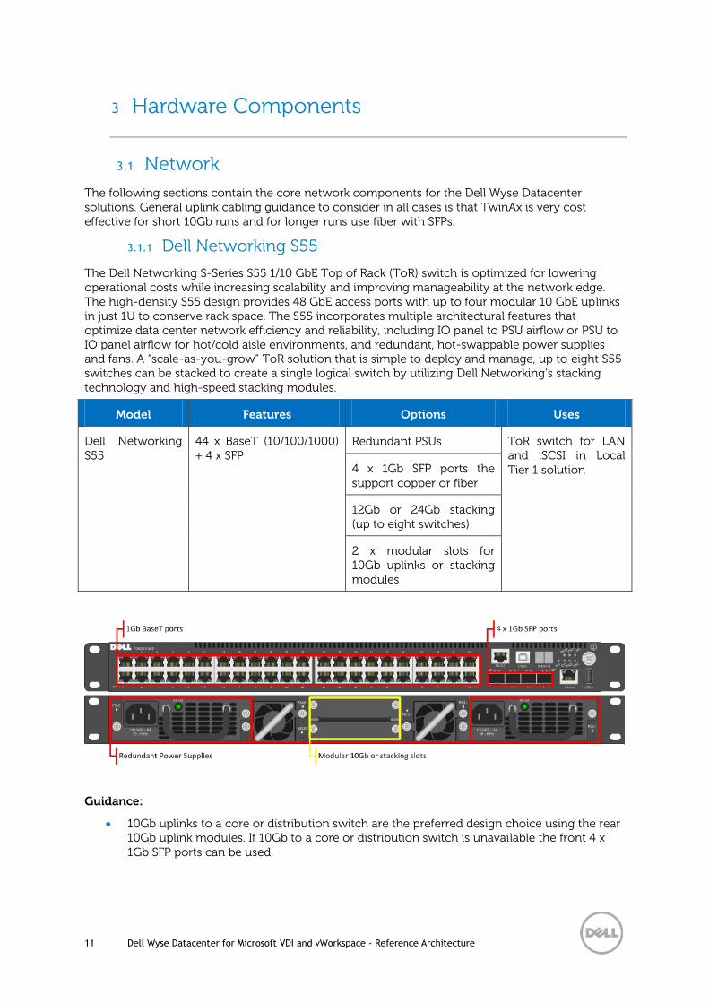
3.1.1 Dell Networking S55
The Dell Networking S-Series S55 1/10 GbE Top of Rack (ToR) switch is optimized for lowering operational costs while increasing scalability and improving manageability at the network edge. The high-density S55 design provides 48 GbE access ports with up to four modular 10 GbE uplinks in just 1U to conserve rack space. The S55 incorporates multiple architectural features that optimize data center network efficiency and reliability, including IO panel to PSU airflow or PSU to IO panel airflow for hot/cold aisle environments, and redundant, hot-swappable power supplies and fans. A “scale-as-you-grow” ToR solution that is simple to deploy and manage, up to eight S55 switches can be stacked to create a single logical switch by utilizing Dell Networking’s stacking technology and high-speed stacking modules.
Model Features Options Uses
Dell Networking S55
44 x BaseT (10/100/1000) + 4 x SFP
Redundant PSUs ToR switch for LAN and iSCSI in Local Tier 1 solution 4 x 1Gb SFP ports the
support copper or fiber
12Gb or 24Gb stacking (up to eight switches)
2 x modular slots for 10Gb uplinks or stacking modules
Guidance:
10Gb uplinks to a core or distribution switch are the preferred design choice using the rear 10Gb uplink modules. If 10Gb to a core or distribution switch is unavailable the front 4 x 1Gb SFP ports can be used.

12 Dell Wyse Datacenter for Microsoft VDI and vWorkspace - Reference Architecture
The front four SFP ports can support copper cabling and can be upgraded to optical if a longer run is needed.
For additional information on the S55 switch and Dell Networking, please visit: LINK
3.1.1.1 Dell Networking S55 Stacking
The ToR switches in the Network layer can be optionally stacked with additional switches, if greater port count or redundancy is desired. Each switch will need a stacking module plugged into a rear bay and connected with a stacking cable. The best practice for switch stacks greater than two is to cable in a ring configuration with the last switch in the stack cabled back to the first. Uplinks need to be configured on all switches in the stack back to the core to provide redundancy and failure protection.
Please reference the following Dell Networking whitepaper for specifics on stacking best practices and configuration: LINK
3.2 Servers
3.2.1 PowerEdge T110 II
The PowerEdge T110 II is the tested and validated server platform of choice for the POC, providing high performance at an extremely low price of entry. Supporting the Intel Xeon E3-1200 series of CPUs and up to 32GB RAM, the T110 provides a solid server platform to get started with VDI.
For additional information about the Dell PowerEdge T110 II, please visit: LINK.
3.2.2 PowerEdge R720
The rack server platform for the Dell Wyse Datacenter solution is the best-in-class Dell PowerEdge R720 (12G). This dual socket CPU platform runs the fastest Intel Xeon E5-2600 family of processors,

13 Dell Wyse Datacenter for Microsoft VDI and vWorkspace - Reference Architecture
can host up to 768GB RAM, and supports up to 16 x 2.5” SAS disks. The Dell PowerEdge R720 offers uncompromising performance and scalability in a 2U form factor.
For additional information about the Dell PowerEdge R720, please visit: LINK.
3.2.3 PowerEdge VRTX
The shared infrastructure platform for the Dell Wyse Datacenter solution is the all in one Dell PowerEdge VRTX. Configurable with up to four PowerEdge blade servers and 25 x 2.5” SAS disks in consolidated 5U form factor, the PowerEdge VRTX provides a flexible performance and capacity for small and midsize businesses as well as remote/branch offices of larger enterprises.
For additional information about the Dell PowerEdge VRTX, please visit: LINK
E S T
6 74 52 30 1 14 1512 1310 118 9
SA
S
30
0G
B 1
5k
SA
S
30
0G
B 1
5k
SA
S
30
0G
B 1
5k
SA
S
30
0G
B 1
5k
SA
S
30
0G
B 1
5k
SA
S
30
0G
B 1
5k
SA
S
30
0G
B 1
5k
SA
S
30
0G
B 1
5k
SA
S
30
0G
B 1
5k
SA
S
30
0G
B 1
5k
SA
S
30
0G
B 1
5k
SA
S
30
0G
B 1
5k
SA
S
30
0G
B 1
5k
1 2 3 4ST
21
iDRAC
2
1
3750W750W
5
4
7
61000=O
RG
100=GR
N
10=OF
F
12 x 15K SAS drives option
2 x 15K SAS drives option
8 x 1Gb Network Ports

14 Dell Wyse Datacenter for Microsoft VDI and vWorkspace - Reference Architecture
3.2.3.1 PowerEdge M620
The PowerEdge M620 is a feature-rich, dual-processor, half-height blade server which offers a blend of density, performance, efficiency and scalability. The M620 offers remarkable computational density, scaling up to 16 cores, two socket Intel Xeon processors and 24 DIMMs (768GB RAM) of DDR3 memory in an extremely compact half-height blade form factor. These features make the M620 an ideal server for the PowerEdge VRTX deployments.
For additional information about the Dell PowerEdge VRTX, please visit: LINK

15 Dell Wyse Datacenter for Microsoft VDI and vWorkspace - Reference Architecture
3.3 Storage
3.3.1 EqualLogic PS4100E
The following array can be used for Tier 2 storage of management VM storage and user data up to 500 users. Please refer to the hardware tables in section 2 or the “Uses” column of each array below.
For additional information on the PS4100E array, please visit: LINK
Model Features Options Uses
EqualLogic PS4100E
12 drive bays (NL-SAS/ 7200k RPM), dual HA controllers, Snaps/Clones, Async replication, SAN HQ, 1Gb
12TB – 12 x 1TB HDs Tier 2 array for up to 500 users or less in Local Tier 1 solution model (1Gb)
24TB – 12 x 2TB HDs
36TB – 12 x 3TB HDs
3.3.2 EqualLogic PS6100E
The following array can be used for Tier 2 storage of management VM storage and user data. Please refer to the hardware tables in section 2 or the “Uses” column of each array below.
For additional information on the PS6100E array, please visit: LINK
Model Features Options Uses
EqualLogic PS6100E
24 drive bays (NL-SAS/ 7200k RPM), dual HA controllers, Snaps/Clones, Async replication, SAN HQ, 1Gb, 4U chassis
24TB – 24 x 1TB HDs Tier 2 array for Shared Tier data in local Tier 1 solution model (1Gb)
48TB – 24 x 2TB HDs
72TB – 24 x 3TB HDs
96TB – 24 x 4TB HDs
MANAGEMENT
SERIAL PORT
SERIAL PORT
MANAGEMENT
STANDBY
ON/OFF
ACT
ERR
PWR
ACT
ERR
PWR
STANDBY
ON/OFF
ETHERNET 1
ETHERNET 1
ETHERNET 0
CONTROL MODULE 12
ETHERNET 0
CONTROL MODULE 12
0
4
8
1
5
9
2
6
10
3
7
11
Hard Drives
1Gb Ethernet ports Mgmt ports
12 x NL SAS drives

16 Dell Wyse Datacenter for Microsoft VDI and vWorkspace - Reference Architecture
3.3.3 EqualLogic PS6100XS
For Shared Tier 1, both high-speed, low-latency solid-state disk (SSD) technology and high-capacity HDDs from a single chassis are utilized. The PS6100XS array is a Dell Fluid Data™ solution with a virtualized scale-out architecture that delivers enhanced storage performance and reliability that is easy to manage and scale for future needs.
For additional information on the PS6100E array, please visit: LINK
Model Features Options Uses
EqualLogic PS6100XS
24 drive hybrid array (SSD + 10K SAS), dual HA controllers, Snaps/Clones, Async replication, SAN HQ, 1Gb
13TB – 7 x 400GB SSD + 17 x 600GB 10K SAS
Tier 1 array for Shared Tier 1 solution model (1Gb – iSCSI)
26TB – 7 x 800GB SSD + 17 x 1.2TB 10K SAS
Tier 1 array for Shared Tier 1 solution model requiring greater per user capacity. (1Gb – iSCSI)

17 Dell Wyse Datacenter for Microsoft VDI and vWorkspace - Reference Architecture
3.3.4 EqualLogic Configuration
Each tier of EqualLogic storage is to be managed as a separate pool or group to isolate specific workloads. Manage shared Tier 1 arrays used for hosting VDI sessions together, while managing shared Tier 2 arrays used for hosting management server role VMs and user data together.
3.4 Dell Wyse End Points
3.4.1 Dell Wyse T10D
The T10D handles everyday tasks with ease and also provides multimedia acceleration for task workers who need video. Users will enjoy integrated graphics processing and additional WMV9 & H264 video decoding capabilities from the Marvell ARMADA™ PXA2128 1.2 GHz Dual Core ARM System-on-Chip (SoC) processor. In addition, the T10D is one of the only affordable thin clients to support dual monitors with monitor rotation, enabling increased productivity by providing an extensive view of task work. Designing smooth playback of high bit-rate HD video and graphics in such a small box hasn’t
SERIAL PORT
SERIAL PORT
MANAGEMENT
MANAGEMENT
STANDBY
ON/OFF
STANDBY
ON/OFF
ACT
ERR
PWR
ACT
ERR
PWR
ETHERNET 1ETHERNET 0
CONTROL MODULE 11
ETHERNET 2 ETHERNET 3
ETHERNET 1ETHERNET 0
CONTROL MODULE 11
ETHERNET 2 ETHERNET 3
7 x 400GB SSD + 17 x 600GB 10K SAS
1Gb Ethernet ports Mgmt ports

18 Dell Wyse Datacenter for Microsoft VDI and vWorkspace - Reference Architecture
been at the expense of energy consumption and heat emissions either. Using less than 7 watts of electricity, the T10D’s small size enables discrete mounting options: under desks, to walls, and behind monitors, creating cool workspaces in every respect.
3.4.2 Dell Wyse D10D
Ultra-high performance in a compact package Power users and knowledge workers will love the exceptionally fast speed and power from the new dual-core driven D10D. With a 1.4 GHz AMD G series APU with integrated graphics engine, the D10D handles everything from demanding multimedia applications to business content creation and consumption with ease. The D10D even supports power users’ most demanding workloads: high quality audio and video, unified communications, CAD/CAM, 3D simulation and modelling, HD Flash and multimedia, and dual digital high resolution displays with rotation. Users will enjoy smooth roaming and super-fast 802.11 a/b/g/n wireless at 2.4 and 5 GHz with dual antennas. The D10D is Citrix HDX, Microsoft® RemoteFX, and VMware® Horizon View certified. It also supports legacy peripherals via an optional USB adapter. Averaging 9 watts, each and every D10D contributes – quietly and coolly – to lowering your organization’s carbon footprint, with reduced power usage and emissions.
3.4.3 Dell Wyse D90D8
A strong, reliable thin client, the D90D8 packs dual-core processing power into a compact form factor for knowledge workers who need performance for demanding virtual Windows® desktops and cloud applications. It’s also great for kiosks, and multi-touch displays in a wide variety of environments, including manufacturing, hospitality, retail, and healthcare. It features dual-core processing power and an integrated graphics engine for a fulfilling Windows® 8 user experience. Knowledge workers will enjoy rich content creation and consumption as well as everyday multimedia. Kiosk displays will look great on a thin client that is Microsoft RemoteFX®, Citrix® HDX, VMware PCoIP, and HD video-enabled. Operating with less than 9 watts of energy, the D90D8 offers cool, quiet operations, potentially lowering your overall carbon footprint.
3.4.4 Dell Wyse Z90D8
The versatile Z90D8 gives people the freedom to mix and match a broad range of legacy and cutting edge peripheral devices. Ports for parallel, serial, and USB 3.0 offer fast, flexible connectivity. Like all Dell Wyse cloud clients, the new Dell Wyse Z90D8 is one cool operator. Its energy efficient processor – which out-performs other more power-hungry alternatives – and silent fan-less design, all contribute to help lower an organization’s carbon footprint through power requirements that are a fraction of traditional desktop PCs.

19 Dell Wyse Datacenter for Microsoft VDI and vWorkspace - Reference Architecture
4 Software Components
4.1 Broker Technologies
4.1.1 Microsoft Remote Desktop Services
Microsoft Remote Desktop Services (RDS) accelerates and extends desktop and application deployments to any device, improves remote worker efficiency, and helps secure critical intellectual property while simplifying regulatory compliance. Remote Desktop Services enables virtual desktop infrastructure (VDI), session-based desktops, and applications, allowing users to work anywhere. The core components of RDS are:
Remote Desktop Virtualization Host
Remote Desktop Virtualization Host (RD Virtualization Host) integrates with Hyper-V to deploy pooled or personal virtual desktop collections within your organization.
Remote Desktop Session Host
Remote Desktop Session Host (RD Session Host) enables a server to host RemoteApp programs or session-based (shared) desktops. Users can connect to RD Session Host servers in a session collection to run programs, save files, and use resources on those servers.
Remote Desktop Connection Broker
Remote Desktop Connection Broker (RD Connection Broker) allows users to connect to their existing virtual desktops, RemoteApp programs, and session-based desktops. RD Connection Broker also enables you to evenly distribute the load among RD Session Host servers in a session collection or pooled virtual desktops in a pooled virtual desktop collection.
Remote Desktop Web Access
Remote Desktop Web Access (RD Web Access) enables users to access RemoteApp and Desktop Connection through the Start menu on a computer that is running Windows 8.1, Windows 7, or through a web browser. RemoteApp and Desktop Connection provides a customized view of RemoteApp programs and session-based desktops in a session collection, and RemoteApp programs and virtual desktops in a virtual desktop collection.
Remote Desktop Licensing
Remote Desktop Licensing (RD Licensing) manages the licenses required to connect to a Remote Desktop Session Host server or a virtual desktop. You can use RD Licensing to install, issue, and track the availability of licenses.
Remote Desktop Gateway
Remote Desktop Gateway (RD Gateway) enables authorized users to connect to virtual desktops, RemoteApp programs, and session-based desktops on an internal corporate network from any Internet-connected device.
In Windows Server 2012 R2, Remote Desktop Services offers enhanced support for session shadowing, online storage deduplication, improved RemoteApp behavior, quick reconnect for remote desktop clients, improved compression and bandwidth usage, dynamic display handling, and RemoteFX virtualized GPU support for DX11.1.

20 Dell Wyse Datacenter for Microsoft VDI and vWorkspace - Reference Architecture
For additional information about the enhancements in RDS in Microsoft Windows Server 2012 R2, please visit: LINK
4.1.2 Dell vWorkspace
Dell vWorkspace™ is an enterprise class desktop virtualization management solution which enables blended deployment and support of virtual desktops, shared sessions and virtualized applications. The core components of vWorkspace are:
Connection Broker
The vWorkspace Connection Broker helps users connect to their virtual desktops, applications, and other hosted resource sessions. The user’s [endpoint?] sends a request to the connection broker to access their virtual environment. The connection broker processes the request by searching for available desktops, and then redirects the user to the available managed desktop or application.
Management Database
The vWorkspace Management Database is required to perform administrative functions. The management database stores all the information relevant to a vWorkspace farm, such as configuration data, administrative tasks and results, and information regarding client connections to virtual desktops and RDSH environments.
Management Console
The vWorkspace Management Console is an integrated graphical interface that helps you perform various management and administrative functions and can be installed on any workstation or server.
Data Collector Service
The vWorkspace Data Collector service is a Windows service on RDSH servers, virtual desktops, and Hyper-V hosts in a vWorkspace farm that sends a heartbeat signal and other information to the connection broker.
Hyper-V Catalyst Components
vWorkspace Hyper-V Catalyst Components increase the scalability and performance of virtual computers on Hyper-V Hosts. Hyper-V catalyst components consist of two components: HyperCache and HyperDeploy. HyperCache provides read IOPS savings and improves virtual desktop performance through selective RAM caching of parent VHDs. HyperDeploy manages parent VHD deployment to relevant Hyper-V hosts and enables instant cloning of Hyper-V virtual computers.
Diagnostics and Monitoring
Built on Dell Software’s Foglight platform, vWorkspace Diagnostics and Monitoring provides real-time and historical data for user experience, hypervisor performance, RDSH servers/applications, virtual desktops, Connection Broker servers, Web Access servers, Secure Gateway servers, profile servers, EOP Print servers, and farm databases.
User Profile Management
vWorkspace User Profile Management uses virtual user profiles as an alternative to roaming profiles in a Microsoft Windows environment including virtual desktops and RD Session Hosts. The virtual user profiles eliminate potential profile corruption and accelerate logon and logoff times by combining the use of a mandatory profile with a custom persistence layer designed to preserve user profile settings between sessions.
Web Access

21 Dell Wyse Datacenter for Microsoft VDI and vWorkspace - Reference Architecture
vWorkspace Web Access is a web application that acts as a web-based portal to a vWorkspace farm. It helps users to retrieve the list of available applications and desktops by using their web browser. After successful authentication, their published desktops and applications are displayed in the web browser.
Secure Gateway
vWorkspace Secure Gateway is an SSL gateway that simplifies the deployment of applications over the Internet and can provide proxy connections to vWorkspace components such as RDP sessions, the Web Access client, and connection brokers.
EOP Print Server
vWorkspace EOP Print is a single-driver printing solution that satisfies both client-side and network printing needs in a vWorkspace environment by providing bandwidth usage control, intelligent font embedding, native printer feature support and clientless support for LAN connected print servers and remote site print servers.
vWorkspace 8.0 MR1 includes support for Microsoft Windows Server R2, Windows 8.1, Lync 2013, and App-V 5.0 as well as provides several enhancements to Diagnostics and Monitoring, Hyper-V Catalyst Components, Dell EOP and more.
For additional information about the enhancements in Dell vWorkspace 8.0 MR1, please visit: LINK
4.2 Hypervisor Platforms
4.2.1 Microsoft Hyper-V
Microsoft Hyper-V™ is a scalable and feature-rich virtualization platform that helps organizations of all sizes realize considerable cost savings and operational efficiencies. Hyper-V in Windows Server 2012 R2 now supports an industry leading 320 logical processors, 4TB of physical memory, 64TB virtual disks, and 1,024 active virtual machines per host as well as 64-node clusters and 8,000 virtual machines per cluster.
For additional information about the enhancements to Hyper-V in Microsoft Windows Server 2012 R2, please visit: LINK
4.3 Operating Systems
4.3.1 Microsoft Windows Server 2012 R2
Microsoft Windows Server 2012 R2 is the latest iteration of the Windows Server operating system environment. This release introduces a host of new features and enhancements, including virtualization, storage, networking, management, security and applications. With this release also come the introduction of Microsoft Cloud OS and an update of products and services to further enable customers’ shift to cloud enablement.
For additional information about the enhancements in Microsoft Windows Server 2012 R2, please visit: LINK
4.3.2 Microsoft Windows 8.1
Microsoft Windows 8.1 is an update to the latest Windows desktop operating system, providing several user centric features. With updates to the user interface, applications, online services, security and more, Windows 8.1 helps keeps a consistent user experience across virtual and physical instances.
For additional information about the enhancements in Microsoft Windows 8.1, please visit: LINK
22 Dell Wyse Datacenter for Microsoft VDI and vWorkspace - Reference Architecture
4.4 Application Virtualization
Microsoft Application Virtualization (App-V) provides multiple methods to deliver virtualized applications to RDS environments, virtual desktops, physical desktops, connected as well as disconnected clients. App-V can help reduce the costs and time associated with managing gold master VM and PC images with integrated applications. App-V also removes potential conflicts, such as legacy application compatibility, since virtualized applications are never installed on an end point. Once an application has been packaged using the Microsoft Application Virtualization Sequencer, it can be saved to removable media, streamed to desktop clients or presented to session-based users on a RDSH host. App-V provides a scalable framework that can be managed by System Center Configuration Manager for a complete management solution.
To learn more about application virtualization and how it integrates into a RDS environment please visit: LINK
For more information about vWorkspace and App-V integration, reviews the administration guide: LINK

23 Dell Wyse Datacenter for Microsoft VDI and vWorkspace - Reference Architecture
5 Solution Architecture for Microsoft Remote
Desktop Services and Dell vWorkspace
5.1 Overview
This solution architecture follows a distributed model where solution components exist in layers. The Compute layer is where VDI desktop VMs execute, the Management layer being dedicated to the broker management role VMs. Both layers, while inextricably linked, scale independently.
5.1.1 RDS Deployment Options
Microsoft RDS provides a number of VDI options to meet your needs, all within a single, simple, wizard-driven environment that is easy to set up and manage.
Sessions, hosted by the RDSH role (formerly Terminal Services), provide easy access to a densely shared session environment. Each RDP-based session shares the total available server resources with all other sessions logged in concurrently on the server. This is the most cost effective option and a great place to start with Microsoft RDS. (An RDS CAL is required for each user or device accessing this type of environment.)
Pooled VMs are the non-persistent user desktop VMs traditionally associated with VDI. Each user VM is assigned a dedicated slice of the host server’s resources to guarantee the performance of each desktop. The desktop VM is dedicated to a single user while in use then returned to the pool at logoff or reboot and reset to a pristine gold image state for the next user. Applications can be built into gold images or published via RemoteApp. (An RDS CAL is required for each user or device accessing this type of environment.)
Personal VMs are persistent 1-to-1 desktop VMs assigned to a specific entitled user. All changes made by Personal VM users will persist through logoffs and reboots making this a truly personalized computing experience. (An RDS CAL is required for each user or device accessing this type of environment.)
5.1.2 vWorkspace Deployment Options
Dell vWorkspace provides a number of delivery options to meet your needs, all within a single, simple, wizard-driven environment that is easy to set up and manage.
RD Session Host Sessions – Provide easy access to a densely shared session environment. vWorkspace RD Session Hosts can deliver full desktops or seamless application sessions from Windows Server Virtual Machines running Windows Server 2003 R2 (32 or 64 Bit), 2008 (32 or 64 bit), 2008 R2, 2012, and 2012 R2. RD Session Host Sessions are well-suited for task based workers using office productivity and line of business applications, without needs for supporting complex peripheral devices or applications with extreme memory or CPU requirements.
Computer Groups Types – Computer Groups can be for virtual or physical computers running Windows XP Pro to Windows 8 Enterprise or Server 2003 R2 to 2012 R2. Additionally there is limited support for Linux computer groups, but Linux is outside of the scope of this reference architecture.
o Desktop Cloud – provides users with access to a single virtual machine from a pool of available virtual machines on one or more non-clustered Hyper-V Servers with local storage. Desktop Clouds are elastic in nature and automatically expand as additional Hyper-V Compute Hosts are added to vWorkspace. New Compute

24 Dell Wyse Datacenter for Microsoft VDI and vWorkspace - Reference Architecture
Hosts automatically receive instant copies of the virtual machine templates, from which they provision new virtual machines locally. Desktop Cloud virtual machines are temporarily assigned to a user or device at logon, and at logoff are re-provisioned from the parent VHDX (instant copy of the virtual machine template). Desktop Cloud virtual machines are well suited for task based workers using office productivity and line of business applications.
o Temporary Virtual Desktop – are the non-persistent user desktop VMs traditionally associated with VDI. Each desktop VM is assigned a dedicated portion of the host server’s resources to guarantee the performance of each desktop. The desktop VM is dedicated to a single user or device while in use then returned to the computer group at logoff, or rebooted and reset to a pristine gold image state for the next user. Applications can be built into gold images or published via RemoteApp. A Microsoft VDA license is required for each non-Microsoft Software Assurance covered device accessing this type of environment.
o Persistent Virtual Desktop Groups – 1-to-1 desktop VMs assigned to a specific entitled user or device. All changes made by Personal VM users will persist through logoffs and reboots making this a truly personalized computing experience. A Microsoft VDA license is required for each non- Microsoft Software Assurance covered device accessing this type of environment.
o Physical Computers – Like Virtual Desktop Computer Groups, Physical Computers can be persistently or temporarily assigned to users or devices. Common use cases for connections to physical computers are remote software development and remote access to one’s office PC.
Please contact Dell or Microsoft for more information on licensing requirements for VDI.

25 Dell Wyse Datacenter for Microsoft VDI and vWorkspace - Reference Architecture
5.2 Compute Layer
5.2.1 Local Tier 1
In the Local Tier 1 model, pooled desktop and shared sessions execute on local storage on each Compute host. vWorkspace Hyper-V Catalyst Components or the RDVH role for RDS is installed in the Hyper-V parent partition. The physical memory configuration varies slightly as to whether it will be hosting pooled desktops or RDSH VMs as seen below. Up to four RDSH VMs may be provisioned to support the total user session count. Due to the local disk requirement in the Compute layer, this model supports rack servers only.
Local Tier 1 Compute Host (Pooled) PowerEdge R720
Local Tier 1 Compute Host (RDSH) PowerEdge R720
2 x Intel Xeon E5-2690v2 Processor (3.0Ghz) 2 x Intel Xeon E5-2690v2 Processor (3.0Ghz)
256GB Memory (16 x 16GB DIMMs @ 1600Mhz) 128GB Memory (8 x 16GB DIMMs @ 1600MHz)
Microsoft Windows Server 2012 R2 Hyper-V Microsoft Windows Server 2012 R2 Hyper-V
12 x 300GB 15K SAS 6Gbps disks 12 x 300GB 15K SAS 6Gbps disks
PERC H710P Integrated RAID Controller – RAID10
PERC H710P Integrated RAID Controller –
RAID10
Broadcom 5720 1Gb QP NDC (LAN) Broadcom 5720 1Gb QP NDC (LAN)
Broadcom 5719 1Gb QP NIC (LAN) Broadcom 5719 1Gb QP NIC (LAN)
iDRAC7 Enterprise w/ vFlash, 8GB SD iDRAC7 Enterprise w/ vFlash, 8GB SD
2 x 750W PSUs 2 x 750W PSUs
For the 10-Seat Trial Kit, all VDI server roles and desktop sessions are hosted on a single server in this model so there is no need for external storage. Higher scale and HA options are not offered with this bundle.
10 User Compute Host PowerEdge T110 II
1 x Intel Xeon E3-1220 V2 (3.1Ghz)
32GB Memory (4 x 8GB DIMMs @ 1600Mhz) (VDI)
Microsoft Windows Server 2012 Hyper-V
4 x 500GB SATA 7.2k Disks RAID 10 (OS + VDI)
PERC H200 Integrated RAID Controller
Broadcom 5722 1Gb NIC (LAN)
305W PSU
5.2.2 Shared Tier 1
In the Shared Tier 1 model, virtual desktop sessions execute on shared storage so there is no need for additional local disks on each server. Dedicated connectivity to the shared storage will be facilitated via Microsoft Scale Out File Servers. All other Compute host configurations are the same as seen in the Local Tier 1 model.

26 Dell Wyse Datacenter for Microsoft VDI and vWorkspace - Reference Architecture
Shared Tier 1 Compute Host PowerEdge R720
2 x Intel Xeon E5-2690v2 Processor (3.0Ghz)
256GB Memory (16 x 16GB DIMMs @ 1600Mhz)
Microsoft Windows Server 2012 R2 Hyper-V
2 x 300GB 15K SAS 6Gbps disks
PERC H710P Integrated RAID Controller – RAID1
Broadcom 5720 1Gb QP NDC (LAN)
Broadcom 5719 1Gb QP NIC (LAN)
iDRAC7 Enterprise w/ vFlash, 8GB SD
2 x 750W PSUs
5.2.3 Shared Infrastructure
The Shared Infrastructure model is similar to the Shared Tier 1 model in that virtual desktop sessions execute on shared storage. The PowerEdge M620 blade servers are configured in a similar fashion to the R720s for Shared Tier 1.
Shared Infrastructure Compute/Mgmt Host PowerEdge M620
2 x Intel Xeon E5-2690v2 Processor (3.0Ghz)
256GB Memory (16 x 16GB DIMMs @ 1600Mhz)
Microsoft Windows Server 2012 Hyper-V
2 x 300GB 15K SAS 6Gbps disks
PERC H710P Integrated RAID Controller – RAID1
Broadcom 57810-k 1Gb/ 10Gb DP KR NDC
PCIe mezz cards for fabric B and C (included)
iDRAC7 Enterprise w/ vFlash, 8GB SD
5.2.4 Graphics Acceleration
Graphics acceleration is offered as a deployment option and alternate configuration for Compute hosts to support shared graphics virtual desktops. For VRTX the Compute host configuration is the same for both graphics and non-graphics options. For LT1 and ST1, the Compute host configuration depends on the architecture model and graphics card model.
Local Tier 1 Compute Host (Graphics) PowerEdge R720
Shared Tier 1 Compute Host (Graphics) PowerEdge R720
2 x Intel Xeon E5-2680v2 Processor (2.8Ghz) 2 x Intel Xeon E5-2680v2 Processor (2.8Ghz)
256GB Memory (16 x 16GB DIMMs @ 1600Mhz) 256GB Memory (16 x 16GB DIMMs @ 1600Mhz)
Microsoft Windows Server 2012 R2 Hyper-V Microsoft Windows Server 2012 R2 Hyper-V
12 x 300GB 15K SAS 6Gbps disks 2 x 300GB 15K SAS 6Gbps disks
PERC H710P Integrated RAID Controller – RAID10
PERC H710P Integrated RAID Controller – RAID1
Broadcom 5720 1Gb QP NDC (LAN) Broadcom 5720 1Gb QP NDC (LAN)
Broadcom 5719 1Gb QP NIC (LAN) Broadcom 5719 1Gb QP NIC (LAN)
iDRAC7 Enterprise w/ vFlash, 8GB SD iDRAC7 Enterprise w/ vFlash, 8GB SD
2 x 1100W PSUs 2 x 750W PSUs

27 Dell Wyse Datacenter for Microsoft VDI and vWorkspace - Reference Architecture
AMD graphics cards are supported as show below.
AMD FirePro™ S7000
AMD FirePro™ S9000
AMD FirePro™ W7000
Number of GPUs 1 1 1
Number of Cores 1280 1792 1280
Total Memory/card 4GB 6GB 6GB
Architecture Model LT1, ST1 LT1, ST1 VRTX
Max # of Cards/host 3 2 3
Number of Users 75 85 75
5.2.4.1 GPU memory utilization for RemoteFX vGPU enabled VMs
In Windows 8.1, the maximum VRAM allocation is dynamic and depends on the minimum amount of system memory that the virtual machine starts with. The dedicated VRAM is either 128MB or 256MB depending on the resolution and number of monitors assigned to the virtual machine. The shared VRAM allocated varies between 64MB and 1GB depending on the minimum amount of system memory that is assigned to the virtual machine when it starts. The formula used to determine the amount of shared memory is:
TotalSystemMemoryAvailableForGraphics = MAX(((TotalSystemMemory - 512) / 2), 64MB)
With a minimum system memory configured at 512MB, virtual machines would get 64MB of shared memory and the following total VRAM:
Maximum Resolution
Maximum number of monitors in virtual machine setting
1 monitor 2 monitors 4 monitors 8 monitors
1024 x 768 192MB 320MB 320MB 320MB
1280 x 1024 192MB 320MB 320MB 320MB
1600 x 1200 192MB 320MB 320MB
1920 x 1200 192MB 320MB 320MB
2560 x 1600 320MB 320MB
For additional information about Microsoft RemoteFX, please visit: LINK
5.2.5 Unified Communications
Unified communications is offered as a deployment option to support instant messaging and user conferencing enabled by Microsoft Lync and the VDI Plugin. The Compute host configuration does not change for this deployment option. Pooled and Personal virtual desktops are supported.
For additional information about the Microsoft Lync VDI 2013 plugin, please visit: LINK

28 Dell Wyse Datacenter for Microsoft VDI and vWorkspace - Reference Architecture
5.3 Management Layer
The Management host configuration consists of VMs running in Hyper-V child partitions with the pertinent RDS or vWorkspace roles enabled. The VMs execute on shared storage through iSCSI connectivity. No RDS or vWorkspace roles need to be enabled in the parent partition of Management hosts. The Management hosts have reduced RAM and CPU, do not require local disk to host the management VMs, and are identical for both the Local and Shared Tier 1 models.
Local/Shared Tier 1 Management Host PowerEdge R720
2 x Intel Xeon E5-2680v2 Processor (2.8Ghz)
64GB Memory (4 x 16GB DIMMs @ 1600Mhz)
Microsoft Windows Server 2012 R2 Hyper-V
2 x 300GB 15K SAS 6Gbps disks
PERC H710P Integrated RAID Controller – RAID1
Broadcom 5720 1Gb QP NDC
Broadcom 5719 1Gb QP NIC
iDRAC7 Enterprise w/ vFlash, 8GB SD
2 x 750W PSUs
The management role requirements for the base solution are summarized below. Use data disks for role-specific application files/ data, logs, IIS web files, etc. in the management volume. Present Tier 2 volumes with a special purpose (called out above) in the format specified below based upon broker technology:
RDS
Role vCPU Startup RAM (GB)
Dynamic Memory NIC OS vDisk (GB)
Tier 2 Volume (GB)
Min|Max Buffer Weight
RD Connection Broker & RD Licensing
2 4 512MB|8GB 20% Med 1 40 -
RD Web Access & RD Gateway
2 4 512MB|8GB 20% Med 1 40 -
File Server 1 4 512MB|8GB 20% Med 1 40 2048
TOTALS 5 12 1.5GB|24GB 3 120 2048
vWorkspace
Dedicated Management Layer
Role vCPU Startup RAM (GB)
Dynamic Memory NIC OS vDisk (GB)
Tier 2 Volume (GB)
Min|Max Buffer Weight
Connection Broker & RD Licensing
4 4 512MB|8GB 20% Med 1 40 -
vWorkspace Diagnostics and Monitoring
2 4 512MB|6GB 20% Med 1 60 -
29 Dell Wyse Datacenter for Microsoft VDI and vWorkspace - Reference Architecture
Role vCPU Startup RAM (GB)
Dynamic Memory NIC OS vDisk (GB)
Tier 2 Volume (GB)
Min|Max Buffer Weight
Web Access & Secure Gateway
2 4 512MB|6GB 20% Med 1 40 -
Profiles Storage Server &
Universal Print Server
2 4 512MB|6GB 20% Med 1 60 -
File Server 1 4 512MB|6GB 20% Med 1 40 2048
SQL Server 4 8 512MB|10GB 20% Med 1 40 210
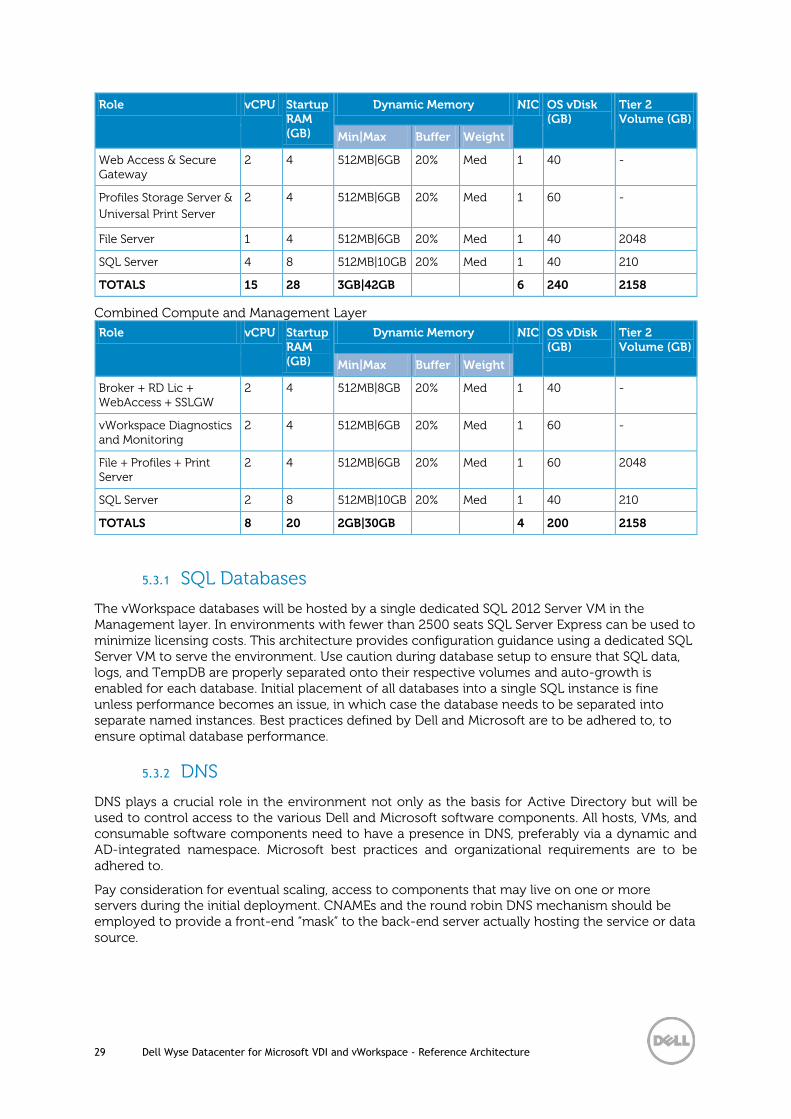
TOTALS 15 28 3GB|42GB 6 240 2158
Combined Compute and Management Layer
Role vCPU Startup RAM (GB)
Dynamic Memory NIC OS vDisk (GB)
Tier 2 Volume (GB)
Min|Max Buffer Weight
Broker + RD Lic + WebAccess + SSLGW
2 4 512MB|8GB 20% Med 1 40 -
vWorkspace Diagnostics and Monitoring
2 4 512MB|6GB 20% Med 1 60 -
File + Profiles + Print Server
2 4 512MB|6GB 20% Med 1 60 2048
SQL Server 2 8 512MB|10GB 20% Med 1 40 210
TOTALS 8 20 2GB|30GB 4 200 2158
5.3.1 SQL Databases
The vWorkspace databases will be hosted by a single dedicated SQL 2012 Server VM in the Management layer. In environments with fewer than 2500 seats SQL Server Express can be used to minimize licensing costs. This architecture provides configuration guidance using a dedicated SQL Server VM to serve the environment. Use caution during database setup to ensure that SQL data, logs, and TempDB are properly separated onto their respective volumes and auto-growth is enabled for each database. Initial placement of all databases into a single SQL instance is fine unless performance becomes an issue, in which case the database needs to be separated into separate named instances. Best practices defined by Dell and Microsoft are to be adhered to, to ensure optimal database performance.
5.3.2 DNS
DNS plays a crucial role in the environment not only as the basis for Active Directory but will be used to control access to the various Dell and Microsoft software components. All hosts, VMs, and consumable software components need to have a presence in DNS, preferably via a dynamic and AD-integrated namespace. Microsoft best practices and organizational requirements are to be adhered to.
Pay consideration for eventual scaling, access to components that may live on one or more servers during the initial deployment. CNAMEs and the round robin DNS mechanism should be employed to provide a front-end “mask” to the back-end server actually hosting the service or data source.

30 Dell Wyse Datacenter for Microsoft VDI and vWorkspace - Reference Architecture
5.3.2.1 DNS for SQL
To access the SQL data sources, either directly or via ODBC, a connection to the server name\ instance name must be used. To simplify this process, as well as protect for future scaling (HA), instead of connecting to server names directly, alias these connections in the form of DNS CNAMEs. So instead of connecting to SQLServer1\<instance name> for every device that needs access to SQL, the preferred approach would be to connect to <CNAME>\<instance name>.
For example, the CNAME “VDISQL” is created to point to SQLServer1. If a failure scenario was to occur and SQLServer2 would need to start serving data, we would simply change the CNAME in DNS to point to SQLServer2. No infrastructure SQL client connections would need to be touched.

31 Dell Wyse Datacenter for Microsoft VDI and vWorkspace - Reference Architecture
5.4 Storage Layer
5.4.1 Local Tier 1
Choosing the Local Tier 1 storage option means that the Compute hosts use 12 locally installed 300GB 15k drives for the host OS (parent partition) and the pooled desktops or shared session VMs. To achieve the required performance level, RAID 10 must be used across all local disks. A single volume per local Tier 1 Compute host is sufficient to host the provisioned VMs along with their respective temporary data.
Volumes Size (GB)
Storage Array
Purpose File System
OS 135 Tier 1 Host Operating System NTFS
VDI 1600 Tier 1 Pooled + Shared VDI NTFS
5.4.2 Shared Tier 1
Choosing the Shared Tier 1 storage option means that the Compute hosts use two locally installed 300GB 15k drives for the host OS (parent partition). All Tier 2 data will be facilitated through the Shared Tier 1 array. The personal virtual desktops leverage shared storage via Microsoft Scale Out File servers connected to a high performance Dell storage array. A single volume per EqualLogic PS6100XS array is capable of facilitating up to 5000 IOPS for VM hosting purposes.
Volumes Size (GB)
Storage Array
Purpose File System
VDI 6144 Tier 1 Desktop VMs NTFS
Management 500 Tier 2 Management VMs NTFS
User Data 2048 Tier 2 File Server NTFS
The follow is the hardware configuration for the Microsoft Scale Out File Server
Microsoft Scale Out File Server PowerEdge R720
2 x Intel Xeon E5-2680v2 Processor (2.8Ghz)
64GB Memory (4 x 16GB DIMMs @ 1600Mhz)
Microsoft Windows Server 2012 R2
2 x 300GB 15K SAS 6Gbps disks
PERC H710P Integrated RAID Controller – RAID1
Broadcom 5720 1Gb QP NDC
Broadcom 5719 1Gb QP NIC
iDRAC7 Enterprise w/ vFlash, 8GB SD
2 x 750W PSUs
5.4.3 Shared Tier 2
Tier 2 is shared iSCSI storage used to host the management server VMs and user data. The EqualLogic PS4100E array can be used for smaller scale deployments up to 500 users or the PS6100E array for larger scale deployments. Intent to scale should be considered when making the

32 Dell Wyse Datacenter for Microsoft VDI and vWorkspace - Reference Architecture
initial investment. The table below outlines the volume requirements for Tier 2. Larger disk sizes can be chosen to meet the capacity needs of the customer. The user data can be presented either via a VHDX or NTFS pass-through disk. The solution as designed presents all SQL disks using VHDX formats. RAID 50 can be used in smaller deployments but is not recommended for critical environments. The recommendation for larger scale and mission critical deployments with higher performance requirements is to use RAID 10 or RAID 6 to maximize performance and recoverability. The two following tables depict the component volumes required to support a 500 user environment based upon broker technology. Additional management volumes can be created as needed along with size adjustments as applicable for user data and profiles.
RDS
Volumes Size (GB)
Storage Array
Purpose File System
Management 500 Tier 2 RDS VMs, File Server NTFS
User Data 2048 Tier 2 File Server NTFS
User Profiles 20 Tier 2 User profiles NTFS
Templates/ ISO
200 Tier 2 ISO/ gold image storage (optional)
NTFS
vWorkspace
Volumes Size (GB)
Storage Array
Purpose File System
Management 500 Tier 2 vWorkspace VMs, File Server NTFS
User Data 2048 Tier 2 File Server NTFS
User Profiles 20 Tier 2 User profiles NTFS
SQL Data 100 Tier 2 SQL NTFS
SQL Logs 100 Tier 2 SQL NTFS
TempDB Data
5 Tier 2 SQL NTFS
TempDB Logs
5 Tier 2 SQL NTFS
SQL Witness 1 Tier 2 SQL (optional) NTFS
Templates/ ISO
200 Tier 2 ISO/ gold image storage (optional)
NTFS
5.4.4 Shared Infrastructure
The VRTX chassis contains up to 25 available 2.5” SAS disks to be shared with each server blade in the cluster.
Solution Model Features Tier 1 Storage (VDI disks) Tier 2 Storage (mgmt. + user data)
2 Blade Up to 250 desktops 10 x 300GB 2.5” 15K SAS 5 x 1.2TB 2.5” 10K SAS
4 Blade Up to 500 desktops 20 x 300GB 2.5” 15K SAS 5 x 1.2TB 2.5” 10K SAS

33 Dell Wyse Datacenter for Microsoft VDI and vWorkspace - Reference Architecture
VRTX solution volume configuration:
Volumes Size (GB)
RAID Disk Pool Purpose File System
VDI 1024 10 Tier 1 VDI Desktops NTFS
Management 200 6 Tier 2 Mgmt VMs, File Server NTFS
User Data 2048 6 Tier 2 File Server NTFS
User Profiles 20 6 Tier 2 User profiles NTFS
SQL DATA 100 6 Tier 2 SQL NTFS
SQL LOGS 100 6 Tier 2 SQL NTFS
TempDB Data
5 6 Tier 2 SQL NTFS
TempDB Logs
5 6 Tier 2 SQL NTFS
Templates/ ISO
200 6 Tier 2 ISO/ gold image storage (optional)
NTFS

34 Dell Wyse Datacenter for Microsoft VDI and vWorkspace - Reference Architecture
5.5 Network Layer
5.5.1 Local Tier 1
In the Local Tier 1 architecture, a single Dell Networking S55 switch can be shared among all network connections for both Management and Compute layer components, for the upper limit of the stack. Only the management servers connect to iSCSI shared storage in this model. All ToR traffic has been designed to be layer 2/ switched locally, with all layer 3/ routable VLANs trunked from a core or distribution switch. The following diagrams illustrate the logical data flow in relation to the core switch.
DR
AC
VL
AN
Mg
mt
VL
AN
iSCSI
Mgmt hosts
Compute hosts
Core switch
ToR switches
Tru
nk
SAN
VD
I V
LA
N
SiSi

35 Dell Wyse Datacenter for Microsoft VDI and vWorkspace - Reference Architecture
5.5.1.1 Cabling Diagram
5.5.1.2 Hyper-V Networking
The network configuration in this model will vary slightly between the Compute and Management hosts. The Compute hosts will not need access to iSCSI storage since they are hosting the VDI sessions on local disk. The following outlines the VLAN requirements for the Compute and Management hosts in this solution model:
Compute hosts (Local Tier 1)
o Management VLAN: Configured for hypervisor infrastructure traffic – L3 routed via
core switch
o VDI VLAN: Configured for VDI session traffic – L3 routed via core switch
Management hosts (Local Tier 1)
o Management VLAN: Configured for hypervisor management traffic – L3 routed via
core switch
o iSCSI VLAN: Configured for iSCSI traffic – L2 switched only via ToR switch
o VDI Management VLAN: Configured for VDI infrastructure traffic – L3 routed via
core switch
An optional iDRAC VLAN can be configured for all hardware management traffic – L3
routed via core switch
In this solution architecture, LAN and iSCSI traffic will be segmented in dedicated VLANs but combined within a single switch to minimize the initial network investment. Following best practices and in solutions that may desire larger scales, this traffic should be separated into discrete switches. Each Local Tier 1 Compute host will have a quad port NDC as well as an add-on 1Gb quad port NIC. The LAN traffic from the server to the ToR switch should be configured as a LAG to maximize bandwidth. The Compute hosts will require two NIC teams: One for LAN and the other for management of the Hyper-V parent OS. The LAN team should be connected to a Hyper-V switch, and the parent OS can utilize the Mgmt team directly.
Compute Hosts MGMT Hosts
PS4100E (Tier 2)
1 2 3 4
ST
21
iDRAC
2
1
3750W750W
5
4
7
6
1 2 3 4
ST
21
iDRAC
2
1
3750W750W
5
4
7
6
1000=OR
G
100=GR
N
10=OF
F
1 2 3 4
ST
21
iDRAC
2
1
3750W750W
5
4
7
6
1 2 3 4
ST
21
iDRAC
2
1
3750W750W
5
4
7
6
1000=OR
G
100=GR
N
10=OF
F
ACT32
33
34
35
30
31
28
29
26
27
24
25
40
41
42
43
38
39
36
37
20
21
22
23
18
19
16
17
14
15
12
13
8
9
10
11
6
7
4
5
2
3
0
1
LNK/SPD
RS-232 USB-B STACK IDACTLNK
Ethernet
MasterPSU1
FAN1
PSU2FAN2
SYSALM
USB-A44 45 46 47
Force10 S55
MANAGEMENT
SERIAL PORT
SERIAL PORT
MANAGEMENT
STANDBY
ON/OFF
ACT
ERR
PWR
ACT
ERR
PWR
STANDBY
ON/OFF
ETHERNET 1
ETHERNET 1
ETHERNET 0
CONTROL MODULE 12
ETHERNET 0
CONTROL MODULE 12
SAN
LAN

36 Dell Wyse Datacenter for Microsoft VDI and vWorkspace - Reference Architecture
The Management hosts have a slightly different configuration since they will additionally access iSCSI storage. The add-on NIC for the Management hosts will also be a 1Gb quad port NIC. Three ports of both the NDC and add-on NIC will be used to form two NIC teams and one MPIO pair.
iSCSI should be isolated onto the NIC pair used for MPIO and connections from all three NIC pairs should pass through both the NDC and add-on NIC. The LAN traffic from the server to the ToR switch should be configured as a LAG. VLAN IDs should be specified in the Hyper-V switch and vNICs designated for management OS functions.
Mgmt Roles Desktop VMs File Server
VLAN 10 VLAN 1
0
VLA
N 2
0
SiSi
Core
LAG
NIC Team – LAN
pNIC 1 pNIC 2
Management OS
MGMT
vNIC
Hyper-V Switch
vNIC vNIC
vNIC
NIC Team – Mgmt
pNIC 1 pNIC 2
Force10 S55
vNIC

37 Dell Wyse Datacenter for Microsoft VDI and vWorkspace - Reference Architecture
5.5.2 Shared Tier 1
In the Shared Tier 1 architecture for rack servers, both Management and Compute servers connect to shared storage in this model. All ToR traffic has designed to be layer 2/ switched locally, with all layer 3/ routable VLANs routed through a core or distribution switch. The following diagrams illustrate the server NIC to ToR switch connections, virtual switch assignments, as well as logical VLAN flow in relation to the core switch.
EQL
Mgmt Roles File Server
SiSi
Core
LAG
NIC Team – LAN
1Gb 1Gb
vNICvNIC
Management OS
Cluster/ CSV Live MigrationMGMTvNICvNICvNIC
NIC Team – Mgmt
1Gb 1Gb
MPIO - iSCSI
1Gb 1Gb
Force10 S55
VM Volumes
File Share Volume
Hyper-V Switch
1Gb

38 Dell Wyse Datacenter for Microsoft VDI and vWorkspace - Reference Architecture
5.5.2.1 Cabling Diagram
DR
AC
VL
AN
Mg
mt
VL
AN
iSCSI
Scale Out File Server
ToR switches
Tru
nk
SAN
VD
I V
LA
N
Mgmt hosts
Liv
e M
igra
tio
n V
LA
N
Core switch
SiSi
Compute hosts
MGMT Hosts
1 2 3 4
ST
21
iDRAC
2
1
3750W750W
5
4
7
6
Compute Hosts
Scale Out File Server PS6100XS
ACT32
33
34
35
30
31
28
29
26
27
24
25
40
41
42
43
38
39
36
37
20
21
22
23
18
19
16
17
14
15
12
13
8
9
10
11
6
7
4
5
2
3
0
1
LNK/SPD
RS-232 USB-B STACK IDACTLNK
Ethernet
MasterPSU1
FAN1
PSU2FAN2
SYSALM
USB-A44 45 46 47
Force10 S55
SAN
LAN
1 2 3 4
ST
21
iDRAC
2
1
3750W750W
5
4
7
6
1000=OR
G
100=GR
N
10=OF
F
1 2 3 4
ST
21
iDRAC
2
1
3750W750W
5
4
7
6
1 2 3 4
ST
21
iDRAC
2
1
3750W750W
5
4
7
6
1 2 3 4
ST
21
iDRAC
2
1
3750W750W
5
4
7
6
1000=OR
G
100=GR
N
10=OF
F
1000=OR
G
100=GR
N
10=OF
F
SERIAL PORT
SERIAL PORT
MANAGEMENT
MANAGEMENT
STANDBY
ON/OFF
STANDBY
ON/OFF
ACT
ERR
PWR
ACT
ERR
PWR
ETHERNET 1ETHERNET 0
CONTROL MODULE 11
ETHERNET 2 ETHERNET 3
ETHERNET 1ETHERNET 0
CONTROL MODULE 11
ETHERNET 2 ETHERNET 3

39 Dell Wyse Datacenter for Microsoft VDI and vWorkspace - Reference Architecture
5.5.2.2 Hyper-V Networking
The network configuration in this model will vary slightly between the Compute and Management hosts. The Compute hosts will access the shared storage via SMB and the Scale Out File Server. The Management hosts will access the shared storage via iSCSI. The following outlines the VLAN requirements for the Compute and Management hosts in this solution model:
Compute hosts (Shared Tier 1)
o Management VLAN: Configured for hypervisor management traffic – L3 routed via
core switch
o Live Migration VLAN: Configured for Live Migration traffic – L2 switched only,
trunked from Core
o SMB VLAN: Configured for SMB traffic – L2 switched only via ToR switch
o VDI VLAN: Configured for VDI session traffic – L3 routed via core switch
Management hosts (Shared Tier 1)
o Management VLAN: Configured for hypervisor management traffic – L3 routed via
core switch
o Live Migration VLAN: Configured for Live Migration traffic – L2 switched only,
trunked from Core
o iSCSI VLAN: Configured for iSCSI traffic – L2 switched only via ToR switch
o VDI Management VLAN: Configured for VDI infrastructure traffic – L3 routed via
core switch
An optional iDRAC VLAN can be configured for all hardware management traffic – L3
routed via core switch
Following best practices, iSCSI and LAN traffic will be physically separated into discrete fabrics. Each Shared Tier 1 Compute and Management host will have a 1 Gb quad port NDC as well as a 1Gb quad port NIC. Isolate iSCSI or SMB onto its own virtual switch with redundant ports. Connections from all three virtual switches should pass through both the NDC and add-on NICs per the diagram below. Configure the LAN traffic from the server to the ToR switch as a LAG.
Two NIC teams should be configured, one for the Hyper-V switch and one for the management OS. The desktop VMs will connect to the Hyper-V switch, while the management OS will connect directly to the NIC team dedicated to the management network. The Compute host will be configured with an additional NIC team to connect to shared storage via the Scale Out File Server and SMB. The Management host is configured with Dell MPIO to connect to shared storage via iSCSI.

40 Dell Wyse Datacenter for Microsoft VDI and vWorkspace - Reference Architecture
Management hosts are configured in the same manner as the Local Tier 1 model.
5.5.3 Shared Infrastructure
All ToR traffic connecting to the VRTX integrated switch should be layer 2/ switched locally, with all layer 3/ routable VLANs trunked from a core or distribution switch. The following diagram
SiSi
Core
LAG
NIC Team – LAN
1Gb 1Gb
Management OS
Cluster/ CSV Live MigrationMGMTvNICvNICvNIC
NIC Team – Mgmt
1Gb 1Gb
NIC Team – SMB
1Gb 1Gb
Force10 S55
1Gb
Desktop VMs
vNIC vNIC vNIC
Hyper-V Switch
MPIO - iSCSI
1Gb 1Gb
VM Volumes
SOFS
VM Volumes
EQL
Mgmt Roles File Server
SiSi
Core
LAG
NIC Team – LAN
1Gb 1Gb
vNICvNIC
Management OS
Cluster/ CSV Live MigrationMGMTvNICvNICvNIC
NIC Team – Mgmt
1Gb 1Gb
MPIO - iSCSI
1Gb 1Gb
Force10 S55
VM Volumes
File Share Volume
Hyper-V Switch
1Gb

41 Dell Wyse Datacenter for Microsoft VDI and vWorkspace - Reference Architecture
illustrates the logical relationship of the VRTX chassis to the integrated switch connections, VLAN assignments, as well as logical VLAN flow in relation to the core switch.
The VRTX chassis can be configured with either switched (default) or pass-through modules. The switched method, shown below also the Dell Wyse Datacenter solution default, supports up to eight external ports for uplinks. This solution configuration only makes use of the single A fabric in default form. External uplinks should be cabled and configured in a LAG to support the desired amount of upstream bandwidth.
iDR
AC
VLA
N
Mg
mt
VL
AN
Compute + Mgmt hosts
Core switch
ToR switch
Tru
nk
Internal Storage
VD
I V
LAN
Integrated Switch

42 Dell Wyse Datacenter for Microsoft VDI and vWorkspace - Reference Architecture
5.5.3.1 Cabling Diagram
* Diagram shows Network HA configuration
5.5.3.2 Network HA
For configurations requiring networking HA, this can be achieved by adding Broadcom 5720 1Gb NICs to the PCIe slots in the VRTX chassis that will connect to the pre-populated PCIe mezzanine

43 Dell Wyse Datacenter for Microsoft VDI and vWorkspace - Reference Architecture
cards in each blade server. This provides an alternative physical network path out of the VRTX chassis for greater bandwidth and redundancy using additional fabrics. A PCIe NIC must be added for each blade in the chassis as these connections are mapped 1:1. As you can see by the graphic below, each M620 in the VRTX chassis will use the 10Gb NDC (throttled to 1Gb) in the A fabric to connect to ports on the internal 1Gb switch. The PCIe mezz cards included in the B fabric will be used to connect to ports provided by the external 1Gb NICs in the PCIe slots of the VRTX chassis (one per blade).
Logical representation:
5.5.3.3 Hyper-V Networking
The Hyper-V configuration utilizes NIC teaming to load balance and provide resiliency for network connections. One consolidated virtual switch should be configured for use by both the desktop and management VMs. The following outlines the recommended VLANs for use in the solution:
Compute + Management hosts
o Management VLAN: Configured for hypervisor and broker management traffic – L3
routed via core switch
o VDI VLAN: Configured for VDI session traffic – L3 routed via core switch
o Live Migration VLAN: Configured for Live Migration traffic – L2 switched only,
trunked from Core
o An optional iDRAC VLAN should be configured for the VRTX iDRAC traffic – L3
routed via core switch
Per host Hyper-V virtual switch configuration:

44 Dell Wyse Datacenter for Microsoft VDI and vWorkspace - Reference Architecture
5.5.4 NIC Teaming
Native Windows Server 2012 R2 NIC Teaming is utilized to load balance and provide resiliency for network connections. NIC teaming should be configured in the Hyper-V host using the native Windows server software and assigned to the Hyper-V switch to be used by the VMs. iSCSI should be configured to use MPIO drivers which does not need to be teamed or presented to any VMs. Team interfaces from the Mgmt team should be specified using VLANs so that the individual management OS components can communicate individually. All NICs and switch ports should be set to auto negotiate. Additional vNICs for other management OS functions should be attached to the Mgmt Hyper-V switch. If connecting a NIC team to a Hyper-V switch, ensure that the “Hyper-V port” load balancing mode is selected.
SiSi
Core
pNIC 1 pNIC 2
Hyper-V Switch
vNetworks
MGMT VDILive Migration
Desktop VMs
VLA
N 2
0
vNIC vNIC
vNIC
Mgmt Roles
VLA
N 1
0
vNIC
1 Gb Integrated Switch
Cluster/CSV

45 Dell Wyse Datacenter for Microsoft VDI and vWorkspace - Reference Architecture

46 Dell Wyse Datacenter for Microsoft VDI and vWorkspace - Reference Architecture
5.6 Scaling Guidance
Each component of the solution architecture scales independently according to the desired number of supported users. Brokers scale differently from other management VMs, as does the hypervisor in use.
The components can be scaled either horizontally (by adding additional physical and virtual servers to the server pools) or vertically (by adding virtual resources to the infrastructure)
Eliminate bandwidth and performance bottlenecks as much as possible
Allow future horizontal and vertical scaling with the objective of reducing the future cost of ownership of the infrastructure.
Component Metric Horizontal scalability Vertical scalability
Virtual Desktop Host/Compute Servers
VMs per physical host Additional hosts and clusters added as necessary
Additional RAM or CPU compute power
Broker Servers Desktops per instance (dependent on SQL performance as well)
Additional servers added to the farm
Additional virtual machine resources (RAM and CPU)
RDSH Servers Desktops per instance Additional virtual RDSH servers added to the farm
Additional physical servers to host virtual RDSH servers
Database Services Concurrent connections, responsiveness of reads/ writes
Migrate databases to a dedicated SQL server and increase the number of management nodes
Additional RAM and CPU for the management nodes
File Services Concurrent connections, responsiveness of reads/ writes
Split user profiles and home directories between multiple file servers in the cluster. File services can also be migrated to the optional NAS device to provide high availability.
Additional RAM and CPU for the management nodes
Monitoring Services Managed agents/units (dependent on SQL performance as well)
Add additional monitoring servers and migrate databases to a dedicated SQL server
Additional RAM and CPU for the management nodes
The scalability tables below indicate the solution model and operating system grouped by deployment option.

47 Dell Wyse Datacenter for Microsoft VDI and vWorkspace - Reference Architecture
5.6.1 Shared Sessions
5.6.2 Pooled Desktops
Standard
User
Count
Enhanced
User
Count
Professional
User
Count
Physical
Compute
Servers
Physical
Mgmt
Servers
Tier 2
Storage
Arrays
TOR
Network
Switches
Virtual
RD Session
Hosts
Virtual
Connection
Brokers
Virtual
License
Servers
Virtual
Web
Servers
225 150 100 1 1 1 1 4 1 1 1
1000 750 500 5 1 1 1 20 1 1 1
2000 1350 900 9 1 2 2 36 1 1 2
3000 2100 1400 14 2 3 3 56 2 1 3
4000 2700 1800 18 2 4 3 72 2 1 4
5000 3450 2300 23 2 5 4 92 2 1 5
6000 4050 2700 27 3 6 5 108 3 1 6
7000 4800 3200 32 3 7 5 128 3 1 7
8000 5400 3600 36 4 8 6 144 4 1 8
9000 6000 4000 40 4 9 7 160 4 1 9
10000 6750 4500 45 4 10 7 180 4 2 10
Local Tier 1 - Windows Server 2012 R2 RDSH
Standard
User
Count
Enhanced
User
Count
Professional
User
Count
Shared
Graphics
User Count
Physical
Compute
Servers
Physical
Mgmt
Servers
Tier 2
Storage
Arrays
TOR
Network
Switches
Virtual
Connection
Brokers
Virtual
License
Servers
Virtual
Web
Servers
225 150 100 75 1 1 1 1 1 1 1
1000 750 500 375 5 1 1 1 1 1 1
2000 1350 900 675 9 1 2 2 1 1 1
3000 2100 1400 1050 14 2 3 3 2 1 2
4000 2700 1800 1350 18 2 4 3 2 1 2
5000 3450 2300 1725 23 2 5 4 2 1 2
6000 4050 2700 2025 27 3 6 5 3 1 3
7000 4800 3200 2400 32 3 7 5 3 1 3
8000 5400 3600 2700 36 4 8 6 4 1 4
9000 6000 4000 3000 40 4 9 7 4 1 4
10000 6750 4500 3375 45 4 10 7 4 2 4
Local Tier 1 - Windows 8.1
Standard
User
Count
Enhanced
User
Count
Professional
User
Count
Shared
Graphics
User Count
Physical
Compute
Servers
Physical
Mgmt
Servers
Tier 1
Storage
Arrays
Physical
File
Servers
TOR
Network
Switches
Virtual
Connection
Brokers
Virtual
License
Servers
Virtual
Web
Servers
225 150 100 75 1 1 1 1 1 1 1 1
1000 750 500 375 5 1 2 1 2 1 1 1
2000 1350 900 675 9 1 3 1 3 1 1 2
3000 2100 1400 1050 14 2 5 2 4 2 1 3
4000 2700 1800 1350 18 2 6 2 5 2 1 4
5000 3450 2300 1725 23 2 8 3 6 2 1 5
6000 4050 2700 2025 27 3 9 3 7 3 1 6
7000 4800 3200 2400 32 3 11 4 8 3 1 7
8000 5400 3600 2700 36 4 12 4 9 4 1 8
9000 6000 4000 3000 40 4 14 5 10 4 1 9
10000 6750 4500 3375 45 4 15 5 11 4 2 10
Shared Tier 1 - Windows 8.1

48 Dell Wyse Datacenter for Microsoft VDI and vWorkspace - Reference Architecture
5.6.3 Personal Desktops
Standard
User
Count
Enhanced
User
Count
Professional
User
Count
Shared
Graphics
User Count
Physical
Compute
Servers
Physical
Mgmt
Servers
Tier 1
Storage
Arrays
Physical
File
Servers
TOR
Network
Switches
Virtual
Connection
Brokers
Virtual
License
Servers
Virtual
Web
Servers
225 150 100 75 1 1 1 1 1 1 1 1
1000 750 500 375 5 1 2 1 2 1 1 1
2000 1350 900 675 9 1 3 1 3 1 1 2
3000 2100 1400 1050 14 2 5 2 4 2 1 3
4000 2700 1800 1350 18 2 6 2 5 2 1 4
5000 3450 2300 1725 23 2 8 3 6 2 1 5
6000 4050 2700 2025 27 3 9 3 7 3 1 6
7000 4800 3200 2400 32 3 11 4 8 3 1 7
8000 5400 3600 2700 36 4 12 4 9 4 1 8
9000 6000 4000 3000 40 4 14 5 10 4 1 9
10000 6750 4500 3375 45 4 15 5 11 4 2 10
Shared Tier 1 - Windows 8.1

49 Dell Wyse Datacenter for Microsoft VDI and vWorkspace - Reference Architecture
5.7 Solution High Availability
High availability (HA) is offered to protect each layer of the solution architecture, individually if desired. Following the N+1 model, additional ToR switches for LAN and iSCSI are added to the Network layer and stacked to provide redundancy as required, additional Compute and Management hosts are added to their respective layers, Hyper-V clustering is introduced in the Management layer, and SQL is mirrored or clustered.
The HA options provides redundancy for all critical components in the stack while improving the performance and efficiency of the solution as a whole.
An additional switch is added at the Network layer, which will be configured with the original as a stack, and equally spreading each host’s network connections across both.
At the Compute layer with Local Tier 1 storage, an additional Hyper-V host is added to provide N+1 protection provided for pooled desktops and shared sessions. Failover clusters are utilized with Shared Tier 1 storage for personal desktop HA.
A number of enhancements occur at the Management layer, the first of which is the addition of another host. The Management hosts are configured in a failover cluster to allow live migration of management VMs. All applicable management server roles can be duplicated in the cluster and utilize native load balancing functionality if available. SQL will also receive greater protection through the addition and configuration of a SQL mirror with a witness.
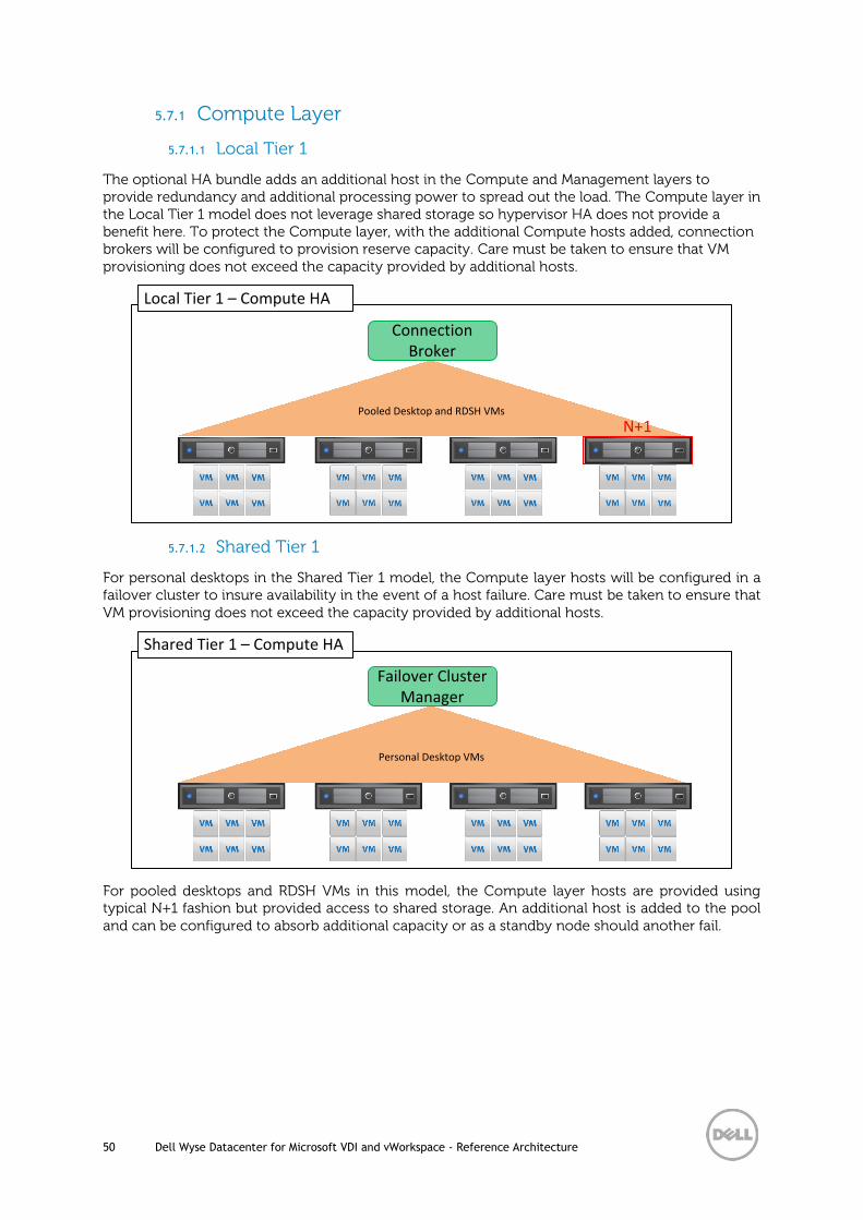
50 Dell Wyse Datacenter for Microsoft VDI and vWorkspace - Reference Architecture
5.7.1 Compute Layer
5.7.1.1 Local Tier 1
The optional HA bundle adds an additional host in the Compute and Management layers to provide redundancy and additional processing power to spread out the load. The Compute layer in the Local Tier 1 model does not leverage shared storage so hypervisor HA does not provide a benefit here. To protect the Compute layer, with the additional Compute hosts added, connection brokers will be configured to provision reserve capacity. Care must be taken to ensure that VM provisioning does not exceed the capacity provided by additional hosts.
5.7.1.2 Shared Tier 1
For personal desktops in the Shared Tier 1 model, the Compute layer hosts will be configured in a failover cluster to insure availability in the event of a host failure. Care must be taken to ensure that VM provisioning does not exceed the capacity provided by additional hosts.
For pooled desktops and RDSH VMs in this model, the Compute layer hosts are provided using typical N+1 fashion but provided access to shared storage. An additional host is added to the pool and can be configured to absorb additional capacity or as a standby node should another fail.
Local Tier 1 – Compute HA
Pooled Desktop and RDSH VMs
Connection Broker
N+1
Shared Tier 1 – Compute HA
Personal Desktop VMs
Failover Cluster Manager

51 Dell Wyse Datacenter for Microsoft VDI and vWorkspace - Reference Architecture
5.7.2 Management Layer
To implement HA for the Management layer for all models, we will also add an additional host but will add a few more layers of redundancy. The following will protect each of the critical infrastructure components in the solution:
The Management hosts will be configured in a failover cluster (Node and Disk Majority).
The storage volume that hosts the Management VMs will be upgraded to a CSV.
SQL Server mirroring is configured with a witness to further protect SQL.
An additional connection broker is added for active/active load balancing.
The management roles which support configurations storage in SQL will be protected via the SQL mirror. The Microsoft license server will be protected from host hardware failure and licensing grace period by default. If desired, it can be optionally protected further via the form of a cold stand-by VM residing on an opposing Management host.
Shared Tier 1 – Compute HA
Pooled Desktop and RDSH VMs
Connection Broker
N+1

52 Dell Wyse Datacenter for Microsoft VDI and vWorkspace - Reference Architecture
The following storage volumes are applicable in a two node Management layer HA scenario:
RDS
Volumes Host Size (GB)
RAID Storage Array
Purpose File System CSV
Management 1 500 50 Tier 2 RDS VMs, File Server NTFS Yes
Management 2 500 50 Tier 2 RDS VMs, File Server NTFS Yes
SQL Data 2 100 50 Tier 2 SQL Data Disk NTFS Yes
SQL Logs 2 100 50 Tier 2 SQL Logs Disk NTFS Yes
SQL TempDB Data
2 5 50 Tier 2 SQL TempDB Data Disk NTFS Yes
SQL TempDB Logs
2 5 50 Tier 2 SQL TempDB Logs Disk NTFS Yes
SQL Witness 1 1 50 Tier 2 SQL Witness Disk NTFS Yes
Quorum 1 - 500MB 50 Tier 2 Hyper-V Cluster Quorum NTFS Yes
User Data - 2048 50 Tier 2 File Server NTFS No
User Profiles - 20 50 Tier 2 User profiles NTFS No
Templates/ ISO
- 200 50 Tier 2 ISO/ gold image storage (optional)
NTFS Yes
vWorkspace
Volumes Host Size (GB)
RAID Storage Array
Purpose File System CSV
Management 1 500 50 Tier 2 vWorkspace Infrastructure
NTFS Yes
Management 2 500 50 Tier 2 vWorkspace Infrastructure
NTFS Yes
SQL Data 2 100 50 Tier 2 SQL Data Disk NTFS Yes
SQL Logs 2 100 50 Tier 2 SQL Logs Disk NTFS Yes
SQL TempDB Data
2 5 50 Tier 2 SQL TempDB Data Disk NTFS Yes
SQL TempDB Logs
2 5 50 Tier 2 SQL TempDB Logs Disk NTFS Yes
SQL Witness 1 1 50 Tier 2 SQL Witness Disk NTFS Yes
Quorum 1 - 500MB 50 Tier 2 Hyper-V Cluster Quorum NTFS Yes
User Data - 2048 50 Tier 2 File Server NTFS No
User Profiles - 20 50 Tier 2 User profiles NTFS No
Templates/ ISO
- 200 50 Tier 2 ISO/ gold image storage (optional)
NTFS Yes

53 Dell Wyse Datacenter for Microsoft VDI and vWorkspace - Reference Architecture
5.7.3 SQL Server High Availability
HA for SQL will be provided via a three server synchronous mirror configuration that includes a witness (High safety with automatic failover). This configuration will protect all critical data stored within the database from physical server as well as virtual server problems. DNS will be used to control access to the active SQL server, please refer to section 5.7.1 for more details. Place the principal VM that will host the primary copy of the data on the first Management host. Place the mirror and witness VMs on the second or later Management hosts. Mirror all critical databases to provide HA protection.
The following article details the step-by-step mirror configuration: LINK
Additional resources can be found in TechNet: LINK1 and LINK2
Please refer to the following Dell Software support article for more information about vWorkspace SQL Server mirror support: LINK
5.7.4 Disaster Recovery and Business Continuity
DR and BC can be achieved natively via Hyper-V Replicas. This technology can be used to replicate VMs from a primary site to a DR or BC site over the WAN asynchronously. Hyper-V Replicas are unbiased as to underlying hardware platform and can be replicated to any server, network, or storage provider. Once the initial replica is delivered from the primary site to the replica site, incremental VM write changes are replicated using log file updates. Multiple recovery points can be stored and maintained, using snapshots, to restore a VM to a specific point in time.

54 Dell Wyse Datacenter for Microsoft VDI and vWorkspace - Reference Architecture
5.8 Microsoft RDS Communication Flow
Pooled Virtual Desktops
RD Virtualization Hosts
Personal Virtual Desktops
RD Session Hosts
Session-based Desktops
Pooled Collection
Session Collection
Gold Master
RD Connection Broker
ActiveDirectory
LDAP
RDP over HTTPS
RD
P
External RDP Client
File Server
RD Gateway
Personal Collection
RD License Server
RD Web Access
HTTPS
Web Client
RDP
RDP Client
Internet
SMB
SMB
LDAP
RPC
RPC
SMB
SAN
Scale Out File Server
SMB
iSCSI

55 Dell Wyse Datacenter for Microsoft VDI and vWorkspace - Reference Architecture
5.9 Dell vWorkspace Communication Flow

56 Dell Wyse Datacenter for Microsoft VDI and vWorkspace - Reference Architecture
6 Customer Provided Stack Components
6.1 Customer Provided Storage Requirements
In the event that a customer wishes to provide his or her own storage array solution for a Dell Wyse Datacenter solution, the following minimum hardware requirements must be met.
Feature Minimum Requirement Notes
Total Tier 2 Storage Space User count and workload dependent
Tier 2 Drive Support 7200rpm NL SAS
Tier 1 IOPS Requirement (Total Users) x 10 IOPS
Tier 2 IOPS Requirement (Total Users) x 1 IOPS
Data Networking 1GbE Ethernet Up to six 1Gb ports per host are required.
Shared Array Controllers 1 with >4GB cache 4GB of cache minimum per controller is recommended for optimal performance and data protection.
RAID Support 10, 6 RAID 10 is leveraged for local Compute host storage and high performance shared arrays. Protect T2 storage via RAID 6.
6.2 Customer Provided Switching Requirements
In the event that a customer wishes to provide his or her own rack network switching solution for a Dell Wyse Datacenter solution, the following minimum hardware requirements must be met.
Feature Minimum Requirement Notes
Switching Capacity Line rate switch
1Gbps Ports 7x per Management server
5x per Compute Server
5x per Storage Array
5x per Scale Out File Server
Dell Wyse Datacenter leverages 1Gbps network connectivity for all network traffic in all solution models.
VLAN Support IEEE 802.1Q tagging and port-based VLAN support.
Stacking Capability Yes The ability to stack switches into a consolidated management framework is preferred to minimize disruption and planning when uplinking to core networks.

57 Dell Wyse Datacenter for Microsoft VDI and vWorkspace - Reference Architecture
7 User Profile and Workload Characterization
It’s important to understand the user workloads when designing a Desktop Virtualization Solution. The Dell Desktop Virtualization Solution methodology includes a Blueprint process to assess and categorize a customer’s environment according to the profiles defined in this section. In the Dell Desktop Virtualization solution this will map directly to the SLA levels we offer in our Integrated Stack. There are three levels, each of which is bound by specific metrics and capabilities.
7.1 Profile Characterization Overview
7.1.1 Standard Profile
The Standard user profile consists of simple task worker workloads. Typically a repetitive application use profile with a non-personalized virtual desktop image. Sample use cases may be a kiosk or call-center use cases which do not require a personalized desktop environment and the application stack is static. In a virtual desktop environment the image is dynamically created from a template for each user and returned to the desktop pool for reuse by other users. The workload requirements for a basic user is the lowest in terms of CPU, memory, network and Disk I/O requirements and will allow the greatest density and scalability of the infrastructure.
User Profile VM vCPU
VM Memory Startup
VM Memory Min/Max
Approx.
IOPS
VDI Session
Disk Space
OS Image Notes
Standard 1 1GB 512MB/2GB 2-3 2.1GB This user workload leverages a shared desktop image emulates a task worker. Only two apps are open simultaneously and session idle time is approximately one hour and forty-five minutes.
7.1.2 Enhanced Profile
The Enhanced user profile consists of email, typical office productivity applications and web browsing for research/training. There is minimal image personalization required in an Enhanced user profile. The workload requirement for an Enhanced user is moderate and most closely matches the majority of office worker profiles in terms of CPU, memory, network and Disk I/O. This will allow moderate density and scalability of the infrastructure.
User Profile VM vCPU
VM Memory Startup
VM Memory Min/Max
Approx.
IOPS
VDI Session
Disk Space
OS Image Notes
Enhanced 2 1GB 512MB/3GB 7-8 3.75GB This user workload leverages a shared desktop image emulates a medium knowledge worker. Up to five applications are open simultaneously and session idle time is approximately 2 minutes.

58 Dell Wyse Datacenter for Microsoft VDI and vWorkspace - Reference Architecture
7.1.3 Professional Profile
The Professional user profile is an advanced knowledge worker. All office applications are configured and utilized. The user has moderate-to-large file size (access, save, transfer requirements). There is some graphics creation or editing done for presentations or content creation tasks. Web browsing use is typically research/training driven, similar to Enhanced Users. The Professional user requires extensive image personalization, for shortcuts, macros, menu layouts etc. The workload requirements for a Professional user are heavier than typical office workers in terms of CPU, memory, network and disk I/O. This will limit density and scalability of the infrastructure.
User Profile VM vCPU
VM Memory Startup
VM Memory Min/Max
Approx.
IOPS
VDI Session
Disk Space
OS Image Notes
Professional 2 1GB 1GB/4GB 10-12 6GB This user workload leverages a shared desktop image emulates a high level knowledge worker. Additional applications are opened simultaneously and session idle time is two minutes
7.1.4 Shared Graphics Profile
The Shared Graphics user profile is identical to the Enhanced user profile except for the addition of a HTML5 graphical application and the RemoteFX vGPU.
User Profile VM vCPU
VM Memory Startup
VM Memory Min/Max
Approx.
IOPS
VDI Session
Disk Space
OS Image Notes
Shared Graphics
2 1GB 512MB/3GB 8-10 3.75GB This user workload leverages a shared desktop image emulates a medium knowledge worker. Up to five applications are open simultaneously and session idle time is approximately 2 minutes.

59 Dell Wyse Datacenter for Microsoft VDI and vWorkspace - Reference Architecture
7.2 Workload Characterization Testing Details
User Profile VM Memory
OS Image Login VSI Workload
Workload Description
Standard 2GB Shared Light This workload emulates a task worker.
The light workload is very light in comparison to medium.
Only two apps are open simultaneously.
Only apps used are Internet Explorer and Excel.
Idle time total is about 1 hour and 45 minutes
Enhanced 3GB Shared Medium This workload emulates a medium knowledge working using Office, IE, PDF, and Java/FreeMind.
Once a session has been started the medium workload will repeat every 48 minutes.
The loop is divided in four segments, each consecutive Login VSI user logon will start a different segments. This ensures that all elements in the workload are equally used throughout the test.
During each loop the response time is measured every 3-4 minutes.
The medium workload opens up to five applications simultaneously.
The keyboard type rate is 160 ms for each character.
Approximately 2 minutes of idle time is included to simulate real-world users.
Each loop will open and use:
Outlook 2010, browse 10 messages.
Internet Explorer, browsing different webpages and a YouTube style video (480p movie trailer) is opened three times in every loop.
Word 2010, one instance to measure response time, one instance to review and edit document.
Doro PDF Printer & Acrobat Reader, the word document is printed and reviewed to PDF.
Excel 2010, a very large randomized sheet is opened.
PowerPoint 2010, a presentation is reviewed and edited.
FreeMind, a Java based Mind Mapping application.

60 Dell Wyse Datacenter for Microsoft VDI and vWorkspace - Reference Architecture
User Profile VM Memory
OS Image Login VSI Workload
Workload Description
Professional 4GB Shared plus Profile Virt, or, Private
Heavy The heavy workload is based on the medium workload except that the heavy workload:
Begins by opening four instances of Internet Explorer. These instances stay open throughout the workload loop.
Begins by opening two instances of Adobe Reader. These instances stay open throughout the workload loop.
There are more PDF printer actions in the workload.
Instead of 480p videos a 720p and a 1080p video are watched.
Increased the time the workload plays a flash game.
The idle time is reduced to 2 minutes.
Shared Graphics
3GB Shared plus Profile Virt, or, Private
Custom Medium (Graphics)
The custom medium workload is based on the medium workload except that it includes:
Microsoft Fishbowl HTML5 application (30+ FPS)

61 Dell Wyse Datacenter for Microsoft VDI and vWorkspace - Reference Architecture
8 Solution Performance and Testing
8.1 Load Generation and Monitoring
8.1.1 Login VSI – Login Consultants
Login VSI is the de-facto industry standard tool for testing VDI environments and server-based computing / terminal services environments. It installs a standard collection of desktop application software (e.g. Microsoft Office, Adobe Acrobat Reader etc.) on each VDI desktop; it then uses launcher systems to connect a specified number of users to available desktops within the environment. Once the user is connected the workload is started via a logon script which starts the test script once the user environment is configured by the login script. Each launcher system can launch connections to a number of 'target' machines (i.e. VDI desktops), with the launchers being managed by a centralized management console, which is used to configure and manage the Login VSI environment.
8.1.2 EqualLogic SAN HQ
EqualLogic SANHQ was used for monitoring the Dell EqualLogic storage units in each bundle. SAN HQ has been used to provide IOPS data at the SAN level; this has allowed the team to understand the IOPS required by each layer of the Shared Tier 1 solution model.
8.1.3 Microsoft Performance Monitor
Microsoft Performance Monitor was utilized to collect resource utilization data for tests performed on the desktop VMs, RD Session Hosts, and Hyper-V platform.
8.2 Testing and Validation
8.2.1 Testing Process
The purpose of the single server testing is to validate the architectural assumptions made around the server stack. Each user load is tested against four runs. First, a pilot run to validate that the infrastructure is functioning and valid data can be captured, and then, three subsequent runs allowing correlation of data.
At different stages of the testing the testing team will complete some manual “User Experience” Testing while the environment is under load. This will involve a team member logging into a session during the run and completing tasks similar to the User Workload description. While this experience will be subjective, it will help provide a better understanding of the end user experience of the desktop sessions, particularly under high load, and ensure that the data gathered is reliable.
For all workloads, the performance analysis scenario will be to launch a user session every 30 seconds. Once all users have logged in, all will run workload activities at steady-state for 48-60 minutes and then logoffs will commence.

62 Dell Wyse Datacenter for Microsoft VDI and vWorkspace - Reference Architecture
8.3 Test Results
This validation was designed to evaluate the capabilities and performance of the new components of the solution:
o Microsoft Windows Server 2012 R2
o Microsoft Windows 8.1
o Dell vWorkspace 8.0 MR1
o Microsoft Scale-Out File Server, SMB 3.0, and Data Deduplication
o Intel Ivy Bridge processors (E5-2690 v2 and E5-2680 v2)
o Microsoft Lync 2013 VDI Plug-in
o Dell EqualLogic PS6100XS
For pooled and shared session desktop tests, compute host validation was performed on Dell R720 servers using local Tier 1 storage and Dell M620 servers on the Dell PowerEdge VRTX shared infrastructure platform. For personal desktop tests, compute host validation was performed on Dell R720 servers while the desktop VHDX files were stored on a data deduplicated SMB 3.0 file share hosted on a highly available Microsoft Scale-Out File Server utilizing Shared Tier 1 storage on a Dell EqualLogic PS6100XS storage array.
With the exception of graphics acceleration tests, all compute hosts used dual Intel E5-2690 v2, 3.0 GHz, 10 core processors. Using Intel Ivy Bridge processors, the M620 can support the same processors as the R720 which was not true for the previous generation Intel Sandy Bridge processors. For the graphics acceleration tests, the compute hosts used dual Intel E5-2680 v2, 2.8 GHz, 10 core processors due to heat and power restraints for a GPU configured server. For the pooled and personal desktop tests, the compute hosts had 256GB of RAM while the compute hosts for the shared session desktop tests used only 128GB of RAM.
For all tests, Hyper-V role on Microsoft Windows Server 2012 R2 was the hypervisor used. Microsoft Windows Server 2012 R2 RDS and Dell vWorkspace 8.0 MR1 were both evaluated as the broker/virtualization components.
Validation was performed using Dell Wyse Datacenter standard testing methodology using LoginVSI 4 load generation tool for VDI benchmarking that simulates production user workloads. The Windows 8.1 VMs were configured for memory and CPU as follows.
User Workload vCPUs Hyper-V Start up Memory
Hyper-V Minimum Memory
Hyper-V
Max
Memory
OS Bit Level
Standard User 1 1GB 512MB 2GB x32
Enhance User / Shared Graphics
2 1GB 512MB 3GB x32
Professional User 2 1GB 1GB 4GB x64
The table below summarizes the user densities that were obtained while remaining in acceptable resource limits (typically below 85% of available resources).

63 Dell Wyse Datacenter for Microsoft VDI and vWorkspace - Reference Architecture
Desktop
Type
Standard Enhanced Professional Shared Graphics
Users/
Host
Steady
State
IOPS/User
Users/
Host
Steady
State
IOPS/User
Users/
Host
Steady
State
IOPS/User
Users/
Host
Steady
State
IOPS/User
Pooled 225 3-4 150 7-8 100 10-11 75-851
8-10
Personal2 225 3-4 150 7-8 100 10-11 75-85
1 8-10
Shared Session
3 225 1-2 150 2-3 100 2-4
1. Maximum users with 3 x AMD S7000 GPU cards is 75 while max with 2 x AMD S9000 GPU cards is 85.
2. Personal test results were achieved using a Shared Tier 1 solution model.
3. Memory requirement for shared session (RDSH) configuration is 50% less than pooled/personal VDI configuration. Additionally, the IOPS per user is up to 80% less for shared sessions.
8.3.1 Provisioning Times
The provisioning time (the time to export the desktop template, create the clone desktop VMs, and prepare the VMs) was recorded during tests. Both RDS and vWorkspace allow the number of desktops being provisioned in parallel (concurrent desktop provisioning) to be adjusted. The default concurrency for RDS is set to 1 while the default for vWorkspace is 10. Although adjusting these to higher values will speed up deployment time, we recommend setting the value no higher than 10 for a production environment to avoid overutilization of resources.
Below is a sample of times observed during testing:
Broker Number
of
Desktops
Desktop Concurrency
Provisioning Time
RDS 150 10 53 minutes
vWorkspace 150 10 26 minutes
In conclusion, vWorkspace demonstrated ~50% faster provisioning times than RDS due to HyperDeploy technology.
8.3.2 Pooled Virtual Desktops
8.3.2.1 Enhanced User Workload (150 Users)
The results below were obtained from the compute host as configured in the Local Tier 1 Production architecture. CPU utilization spiked to 80% which is below the threshold and suggests the system could support more desktops. However, subsequent tests with 10 additional desktops placed the utilization over the threshold for the duration of the steady state so it was determined

64 Dell Wyse Datacenter for Microsoft VDI and vWorkspace - Reference Architecture
that 150 would be the most suitable density. Memory utilization is well below the threshold leaving additional capacity for dynamic memory allocation.
IOPS spiked to 1638 during the logon period from 2:39PM to 3:55PM while users were logging in every 30 seconds. During steady state from 3:56PM to 4:44PM, all users are executing the test workload and IOPS averaged 1017 yielding about 7 IOPS/user. Users began logging off at 4:45PM and completed at 5:00PM during which IOPS peaked at 2689.
Network utilization remained relatively low and well within limits for a 1Gbps switching infrastructure.
8.3.3 Shared Session
8.3.3.1 Enhanced User Workload (150 Users)
For the shared session tests, the RDSH environment was configured in the following manner on the compute host.
Hyper-V Compute Host
RDSH VM1 RDSH VM2 RDSH VM3 RDSH VM4
CPU Resources 40 logical cores (20 physical)
10 vCPUs 10 vCPUs 10 vCPUs 10 vCPUs
Memory (GB) 128 Dynamic
16GB (max 31GB)
Dynamic 16GB (max
31GB)
Dynamic 16GB (max
31GB)
Dynamic 16GB (max
31GB)
The results below were taken from the compute server hosting the four RDSH VMs as configured in the Local Tier 1 Production architecture. CPU utilization spiked to about 78% which is below the threshold and suggests the system could support more sessions. However, memory utilization
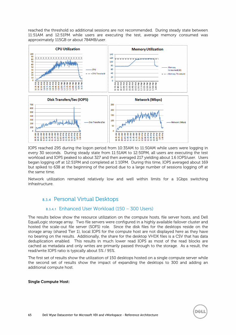
65 Dell Wyse Datacenter for Microsoft VDI and vWorkspace - Reference Architecture
reached the threshold so additional sessions are not recommended. During steady state between 11:51AM and 12:51PM while users are executing the test, average memory consumed was approximately 115GB or about 784MB/user.
IOPS reached 295 during the logon period from 10:35AM to 11:50AM while users were logging in every 30 seconds. During steady state from 11:51AM to 12:50PM, all users are executing the test workload and IOPS peaked to about 327 and then averaged 217 yielding about 1.6 IOPS/user. Users began logging off at 12:51PM and completed at 1:10PM. During this time, IOPS averaged about 169 but spiked to 638 at the beginning of the period due to a large number of sessions logging off at the same time.
Network utilization remained relatively low and well within limits for a 1Gbps switching infrastructure.
8.3.4 Personal Virtual Desktops
8.3.4.1 Enhanced User Workload (150 – 300 Users)
The results below show the resource utilization on the compute hosts, file server hosts, and Dell EqualLogic storage array. Two file servers were configured in a highly available failover cluster and hosted the scale-out file server (SOFS) role. Since the disk files for the desktops reside on the storage array (shared Tier 1), local IOPS for the compute host are not displayed here as they have no bearing on the results. Additionally, the share for the desktop VHDX files is a CSV that has data deduplication enabled. This results in much lower read IOPS as most of the read blocks are cached as metadata and only writes are primarily passed through to the storage. As a result, the read/write IOPS ratio is typically about 5% / 95%.
The first set of results show the utilization of 150 desktops hosted on a single compute server while the second set of results show the impact of expanding the desktops to 300 and adding an additional compute host.
Single Compute Host:
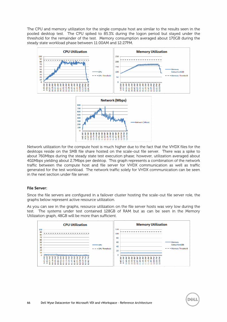
66 Dell Wyse Datacenter for Microsoft VDI and vWorkspace - Reference Architecture
The CPU and memory utilization for the single compute host are similar to the results seen in the pooled desktop test. The CPU spiked to 85.3% during the logon period but stayed under the threshold for the remainder of the test. Memory consumption averaged about 170GB during the steady state workload phase between 11:00AM and 12:27PM.
Network utilization for the compute host is much higher due to the fact that the VHDX files for the desktops reside on the SMB file share hosted on the scale-out file server. There was a spike to about 760Mbps during the steady state test execution phase; however, utilization averaged about 402Mbps yielding about 2.7Mbps per desktop. This graph represents a combination of the network traffic between the compute host and file server for VHDX communication as well as traffic generated for the test workload. The network traffic solely for VHDX communication can be seen in the next section under file server.
File Server:
Since the file servers are configured in a failover cluster hosting the scale-out file server role, the graphs below represent active resource utilization.
As you can see in the graphs, resource utilization on the file server hosts was very low during the test. The systems under test contained 128GB of RAM but as can be seen in the Memory Utilization graph, 48GB will be more than sufficient.

67 Dell Wyse Datacenter for Microsoft VDI and vWorkspace - Reference Architecture
The Network graph represents the amount of VHDX communication seen on the front-end between the compute host and the file servers while the iSCSI graph represents the iSCSI network traffic on the back-end between the file servers and storage array.
On the front-end, network utilization reached a peak of about 551Mbps during the login period from 9:45AM to 10:59AM. During the steady state test phase from 11:00AM to 12:27PM, a brief spike to 496Mbps was seen but the utilization averaged about 175Mbps or 1.2Mbps per desktop. During the logoff period between 12:28PM and 12:44PM, utilization peaked at 339Mbps. On the back-end, iSCSI traffic reached a peak of about 500Mbps during the login period. During the steady state test phase, iSCSI traffic averaged about 197Mbps yielding about 1.3Mbps per desktop.
The picture below shows the I/O graphs for the entire test period with the IOPS high point (1662) for all volumes indicated during the steady state test phase.
IOPS high point (~1625) for the volume containing the desktop VHDX files:

68 Dell Wyse Datacenter for Microsoft VDI and vWorkspace - Reference Architecture
IOPS profile during the steady state test phase from 11:00AM to 12:27PM:
IOPS averaged about 1094 during the steady state period or approximately 7.3 IOPS/User.
Two Compute Hosts – 300 Desktops:
The utilization was similar for both compute hosts involved in this test. The CPU spiked to approximately 90% on one host and about 84% on the other but both stayed under the threshold for the remainder of the test. Memory consumption for both hosts averaged about 170GB during the steady state workload phase between 2:12PM and 3:20PM.
Compute Host 1:

69 Dell Wyse Datacenter for Microsoft VDI and vWorkspace - Reference Architecture
Compute Host 2:
The Network graphs for both hosts represent a combination of the network traffic between the compute hosts and file servers for VHDX communication as well as traffic generated for the test workload. The network traffic solely for VHDX communication can be seen in the next section under file server. There was a spike to about 501Mbps on the first host and about 574Mbps on the second compute host. During the steady state test execution phase from 2:12PM to 3:20PM, the network utilization averaged about 333Mbps on one host and 354Mbps on the other yielding about 2.3Mbps per desktop.
File Server:
Since the file servers are configured in a failover cluster hosting the scale-out file server role, the graphs below represent active resource utilization.
As you can see in the graphs, resource utilization on the file server hosts was very low during the test. The systems under test contained 128GB of RAM but as can be seen in the Memory Utilization graph, 48GB will be more than sufficient.

70 Dell Wyse Datacenter for Microsoft VDI and vWorkspace - Reference Architecture
The Network graph represents the amount of VHDX communication seen on the front-end between the compute hosts and the file servers while the iSCSI graph represents the iSCSI network traffic on the back-end between the file servers and storage array.
On the front-end, network utilization reached a peak of about 589Mbps during the login period from 11:42AM to 2:11PM. During the steady state test phase from 2:12PM to 3:20PM, a brief spike to 633Mbps was seen but the utilization averaged about 358Mbps or 1.2Mbps per desktop. During the logoff period between 3:21PM and 3:41PM, utilization peaked at 486Mbps. On the back-end, iSCSI traffic reached a peak of about 661Mbps during the login period. During the steady state test phase, iSCSI traffic spiked over 605Mbps and averaged about 363Mbps yielding about 1.2Mbps per desktop.
The picture below shows the I/O graphs for the entire test period with the IOPS high point (2489) for all volumes indicated during the steady state test phase.
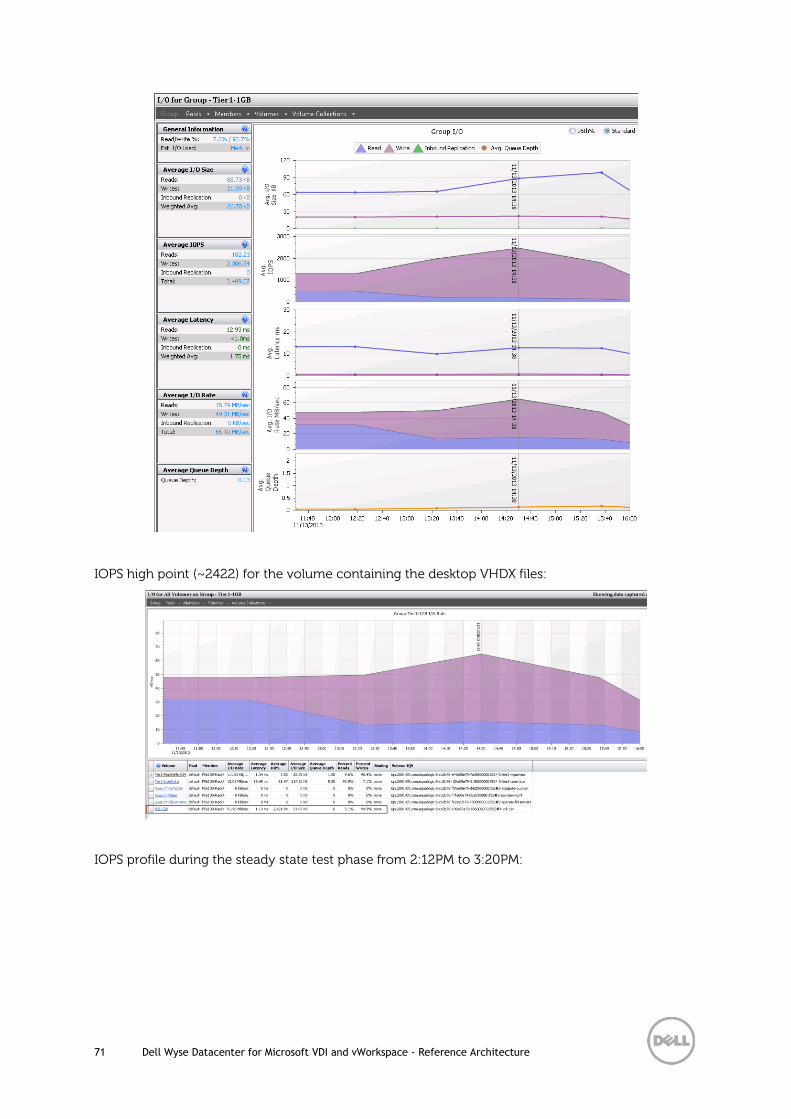
71 Dell Wyse Datacenter for Microsoft VDI and vWorkspace - Reference Architecture
IOPS high point (~2422) for the volume containing the desktop VHDX files:
IOPS profile during the steady state test phase from 2:12PM to 3:20PM:

72 Dell Wyse Datacenter for Microsoft VDI and vWorkspace - Reference Architecture
IOPS averaged about 1847 during the steady state period or approximately 6.2 IOPS/User.
Although the IOPS per user is lower during this 300 desktop test, this does not indicate a trend with adding more desktops and compute hosts as subsequent tests with additional desktops indicates that IOPS/user typically stays in the 7-8 IOPS range.
Data Deduplication:
The picture below shows the deduplication savings (93%) on the volume containing the SMB file share for the personal desktops. This volume contains the VHDX files for 600 personal desktops that are consuming over 9TB of space. With deduplication enabled, only 596GB of space is being used on the storage array.
More details:

73 Dell Wyse Datacenter for Microsoft VDI and vWorkspace - Reference Architecture
All personal desktop tests were performed while the volume hosting the VHDX files was at least at 90% optimized.
8.3.5 Graphics Acceleration
8.3.5.1 Shared Graphics User Workload
The results below were obtained from the compute host as configured in the Local Tier 1 Graphics Acceleration architecture. The server was configured with two AMD S9000 GPU cards and the maximum density reached was 85 desktops. CPU utilization reached about 70% but stayed well below the threshold for the entire test. Memory utilization is well below the threshold and consumption averaged about 151GB (1.8GB per desktop) during the steady state workload phase between 12:10PM and 1:09PM.

74 Dell Wyse Datacenter for Microsoft VDI and vWorkspace - Reference Architecture
IOPS spiked to 1697 during the logon period from 11:42AM to 12:09PM while users were logging in every 20 seconds. During steady state from 12:10PM to 1:09PM, all users are executing the test workload and IOPS averaged 564 yielding about 7 IOPS/user. Users began logging off at 1:10PM and completed at 1:20PM during which occurred a brief IOPS spike to about 2500.
Network utilization hit a spike to 524Mbps during the steady state test phase but averaged about 197Mbps during this period and remained relatively low throughout the test.
GPU Performance Analysis
Although CPU, memory, disk, and network utilization results were well within limits, density was determined by the GPU utilization.
Below is the GPU utilization for the two AMD S9000 cards captured soon after the steady state test phase started:
Process Explorer graph showing GPU utilization during the same period:

75 Dell Wyse Datacenter for Microsoft VDI and vWorkspace - Reference Architecture
Graph below shows the RemoteFX Output FPS for all sessions:

76 Dell Wyse Datacenter for Microsoft VDI and vWorkspace - Reference Architecture
8.3.6 Unified Communications
8.3.6.1 Lync 2013 VDI Plug-in
In a virtual desktop scenario, the Lync 2013 VDI plug-in offloads encoding and decoding of media from the server hosting the desktops to the local client connecting to the desktop. Tests were performed to show the impact of making audio and video calls with and without the plug-in.
Audio Call Sample:
During a call playing the same audio clip, processor utilization within the virtual desktop not paired with the Lync plug-in spiked to about 14% while only spiking to about 7% with the plug-in enabled. Average processor utilization was about 4% with the plug-in and about 5.3% without. On average, this was about a 25% reduction in processor utilization while reaching 50% reduction on spikes.
Video Call Sample:
During a video call, processor utilization within the virtual desktop not paired with the Lync plug-in spiked to about 36% while only spiking to about 3% with the plug-in enabled. Average processor utilization was about 2% with the plug-in and about 25% without. This was about a 92% reduction in processor utilization on average and during spikes.

77 Dell Wyse Datacenter for Microsoft VDI and vWorkspace - Reference Architecture
No discernible difference was noticed in memory utilization although additional testing may show an impact in this area as well.

78 Dell Wyse Datacenter for Microsoft VDI and vWorkspace - Reference Architecture
Acknowledgements
Thanks to Peter Fine, Sr. Principal Architect for Citrix solutions at Dell, for his expertise and contributions to the Dell Wyse Datacenter solutions and reference architectures.
Thanks to Patrick Rouse, Principal Solution Architect for Software and Dell IP solutions at Dell, for his contributions to the Dell Wyse Datacenter solutions and reference architectures.
Thanks to Derrick Isoka, Program Manager at Microsoft, for his knowledge and information regarding Microsoft RemoteFX vGPU configuration.
Thanks to the Microsoft Remote Desktop Services team for their efforts and support of Dell Wyse Datacenter solutions.

79 Dell Wyse Datacenter for Microsoft VDI and vWorkspace - Reference Architecture
About the Authors
Steven Hunt is the Principal Engineering Architect for Microsoft based solutions in the Desktop Virtualization Solutions Group at Dell. Steven has over a decade of experience with Dell (vWorkspace), Microsoft (RDS), Citrix (XenDestop/XenApp) and VMware (View) desktop virtualization solutions.
Senthil Baladhandayutham is the Solutions Development Manager in the Desktop Virtualization Solutions Group at Dell, managing the development and delivery of Enterprise class desktop virtualization solutions based on Dell datacenter components and core virtualization platforms.
Farzad Khosrowpour is a Systems Sr. Principal Engineering Architect in the Desktop Virtualization Solutions Group at Dell. Farzad is recognized for enterprise level technology development and has led various R&D teams across a broad set of solutions and products including storage, servers, data management, and system architectures.
Jerry Van Blaricom is a Sr. Solutions Engineer in the Desktop Virtualization Solutions Group at Dell. Jerry has extensive experience with the design and implementation of a broad range of enterprise systems and is focused on making Dell’s virtualization offerings consistently best in class.
Shruthin Reddy is a Sr. Systems Engineer in the Desktop Virtualization Solutions Group at Dell with extensive experience validating VDI solutions by Microsoft (RDS), VMware (View), and Citrix (XenDesktop).
John Waldron is a Sr. Systems Engineer in the Desktop Virtualization Solutions Group at Dell. John has years of deep operational experience in IT and holds a Bachelor’s degree in Computer Engineering from the University of Limerick.