Deliverable no.: 6.3 - EnergyLab...
18
Deliverable no.: 6.3.1 Assessment of various battery types and compiling of experiences obtained in other projects concerning electrical storage facilities Photo: By & Havn / Ole Malling DONG Energy Daniel Sandermann Jensen 02-16-2016 Public deliverable Confidential deliverable
Transcript of Deliverable no.: 6.3 - EnergyLab...
Deliverable no.: 6.3.1
Assessment of various battery types and compiling of experiences obtained in other projects concerning electrical storage facilities
Photo: By & Havn / Ole Malling
DONG Energy
Daniel Sandermann Jensen 02-16-2016
Public deliverable Confidential deliverable
Preface EnergyLab Nordhavn – New Urban Energy Infrastructures is an exciting project which will continue
until the year of 2019. The project will use Copenhagen’s Nordhavn as a full-scale smart city
energy lab, which main purpose is to do research and to develop and demonstrate future energy
solutions of renewable energy.
The goal is to identify the most cost-effective smart energy system, which can contribute to the
major climate challenges the world are facing.
Budget: The project has a total budget of DKK 143 m (€ 19 m), of this DKK84 m (€ 11 m) funded in
two rounds by the Danish Energy Technology Development and Demonstration Programme
(EUDP).
Forord EnergyLab Nordhavn er et spændende projekt der løber til og med 2019. Projektet vil foregå i
Københavns Nordhavn, og vil fungere som et fuldskala storbylaboratorium, der skal undersøge,
udvikle og demonstrerer løsninger for fremtidens energisystem.
Målet er at finde fremtidens mest omkostningseffektive energisystem, der desuden kan bidrage til
en løsning på de store klimaudfordringer verden står overfor nu og i fremtiden.
Budget: Projektets totale budget er DKK 143 mio. (EUR 19 mio.), hvoraf DKK 84 mio. (EUR 11
mio.) er blevet finansieret af Energiteknologisk Udviklings- og Demonstrationsprogram, EUDP.
Disclaimer [Add standard disclaimer]
Project Information Deliverable no.: 6.3.1 Deliverable title: Assessment of various battery types and compiling of experiences obtained in other projects concerning electrical storage facilities WP title: Battery storage in PV-feeder Task Leader: Ole Michael Pedersen WP Leader: Poul Brath Comment Period: [03, 11, 2016 to 03, 25, 2016] For further information on this specific deliverable, please contact: Daniel Sandermann [email protected] For other information regarding EnergyLab Nordhavn, please contact: EnergyLab Nordhavn Secretariat Center for Electric Power and Energy, DTU Electrical Engineering Richard Petersens Plads Building 325 DK-2800 Kgs. Lyngby Denmark E-mail [email protected] Tlf. +45 45 25 35 54 www.energylabnordhavn.dk
Table of Contents 1. Introduction 7
2. Battery Energy Storage Systems 7 2.1 Electrochemical energy storage 7
2.1.1 Lead-Acid Batteries (Pb-A) 9
2.1.2 Sodium-Sulphur Batteries (NaS) 11
2.1.3 Lithium-ion Batteries 13
2.1.4 Vanadium Redox Batteries (VRB) 16
3. Conclusion 18
4. References 18
Executive Summary As part of the Energylab Nordhavn project,1 DONG Energy Distribution will install a battery energy storage system (BESS). The project will allow for an investigation of both the potential benefits of utilizing the battery as an integrated grid component, and further the potential impacts of a future increased implementation of 3rd party owned storage facilities in the network. To facilitate the investigation of both utility- and commercially owned BESS in the distribution network a range of preliminary analysis and potential collaborations are currently being exploited. This report summarizes the preliminary assessment of various battery types and in addition presents examples of existing applications of the individual technologies.
1 www.energylabnordhavn.dk
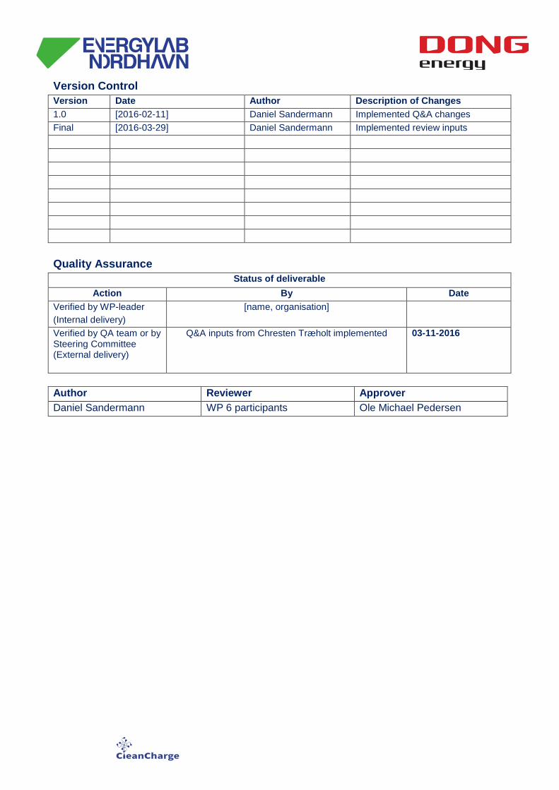
Version Control Version Date Author Description of Changes 1.0 [2016-02-11] Daniel Sandermann Implemented Q&A changes Final [2016-03-29] Daniel Sandermann Implemented review inputs Quality Assurance
Status of deliverable Action By Date
Verified by WP-leader (Internal delivery)
[name, organisation]
Verified by QA team or by Steering Committee (External delivery)
Q&A inputs from Chresten Træholt implemented 03-11-2016
Author Reviewer Approver Daniel Sandermann WP 6 participants Ole Michael Pedersen
1. Introduction As part of the Energylab Nordhavn project2 DONG Energy will install a large-scale energy storage system i.e. a battery energy storage system (BESS). The project will allow for an investigation of both the potential benefits of utilizing the battery as an integrated grid component, and further the potential impacts of a future increased implementation of 3rd party owned storage facilities in the network. The primary objectives for the BESS can be subdivided in the following headlines:
• Testing of the latest BESS technology in a realistic environment • Demonstrate the potential of utilizing energy storage for deferral of infrastructural investments • Demonstrate control protocols and business models for a BESS for both DSO and commercial purposes • Use test data to discuss and recommend the best possible regulatory landscape for energy storage in the
distribution network To facilitate the investigation of both utility- and commercially owned BESS in the distribution network a range of preliminary analysis is presently under development. The present document describes the physical placement of the BESS, which will be situated within a parking garage in the Århusgade district of Nordhavn, and further describes the technological dimensioning of the BESS.
2. Battery Energy Storage Systems
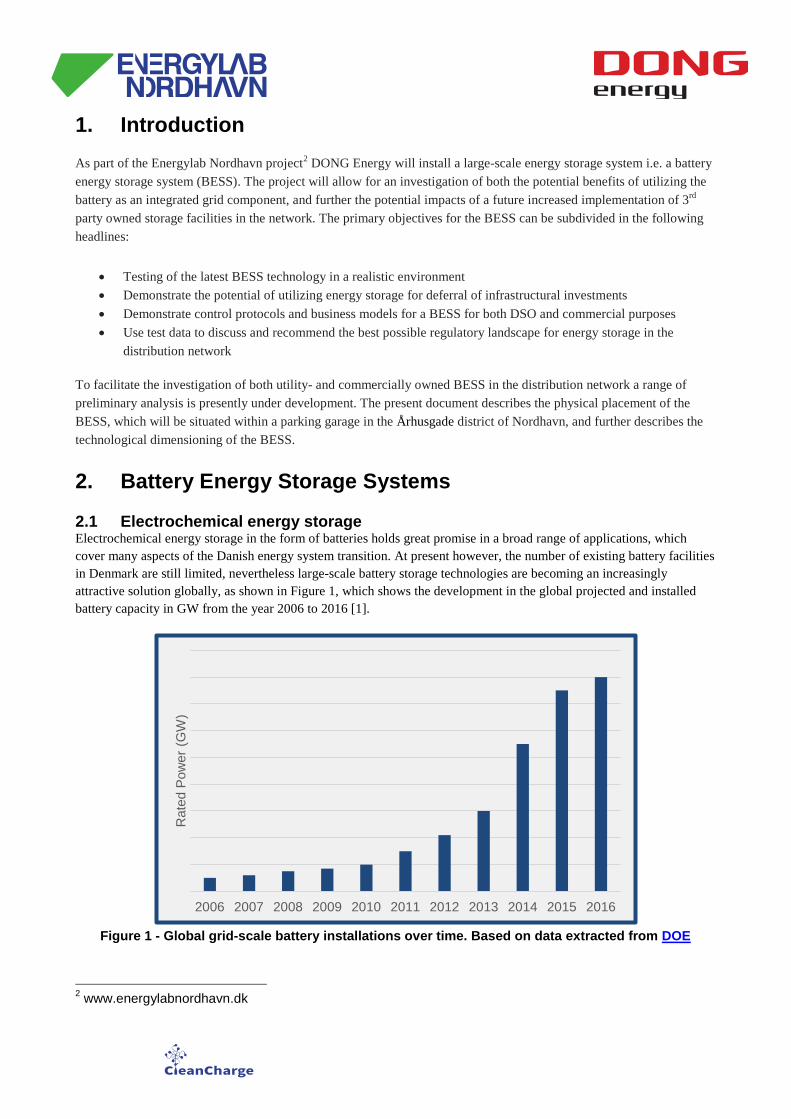
2.1 Electrochemical energy storage Electrochemical energy storage in the form of batteries holds great promise in a broad range of applications, which cover many aspects of the Danish energy system transition. At present however, the number of existing battery facilities in Denmark are still limited, nevertheless large-scale battery storage technologies are becoming an increasingly attractive solution globally, as shown in Figure 1, which shows the development in the global projected and installed battery capacity in GW from the year 2006 to 2016 [1].
Figure 1 - Global grid-scale battery installations over time. Based on data extracted from DOE
2 www.energylabnordhavn.dk
2006 2007 2008 2009 2010 2011 2012 2013 2014 2015 2016
Rat
ed P
ower
(GW
)
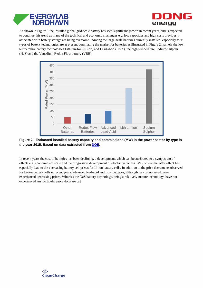
As shown in Figure 1 the installed global grid-scale battery has seen significant growth in recent years, and is expected to continue this trend as many of the technical and economic challenges e.g. low capacities and high costs previously associated with battery storage are being overcome. Among the large-scale batteries currently installed, especially four types of battery technologies are at present dominating the market for batteries as illustrated in Figure 2, namely the low temperature battery technologies Lithium-Ion (Li-ion) and Lead-Acid (Pb-A), the high temperature Sodium-Sulphur (NaS) and the Vanadium Redox Flow battery (VRB).
Figure 2 - Estimated installed battery capacity and commissions (MW) in the power sector by type in the year 2015. Based on data extracted from DOE.
In recent years the cost of batteries has been declining, a development, which can be attributed to a symposium of effects e.g. economies of scale and the progressive development of electric vehicles (EVs), where the latter effect has especially lead to the decreasing battery cell prices for Li-ion battery cells. In addition to the price decrements observed for Li-ion battery cells in recent years, advanced lead-acid and flow batteries, although less pronounced, have experienced decreasing prices. Whereas the NaS battery technology, being a relatively mature technology, have not experienced any particular price decrease [2].
0
50
100
150
200
250
300
350
400
450
OtherBatteries
Redox FlowBatteries
AdvancedLead-Acid
Lithium-ion SodiumSulphur
Rat
ed P
ower
(MW
)
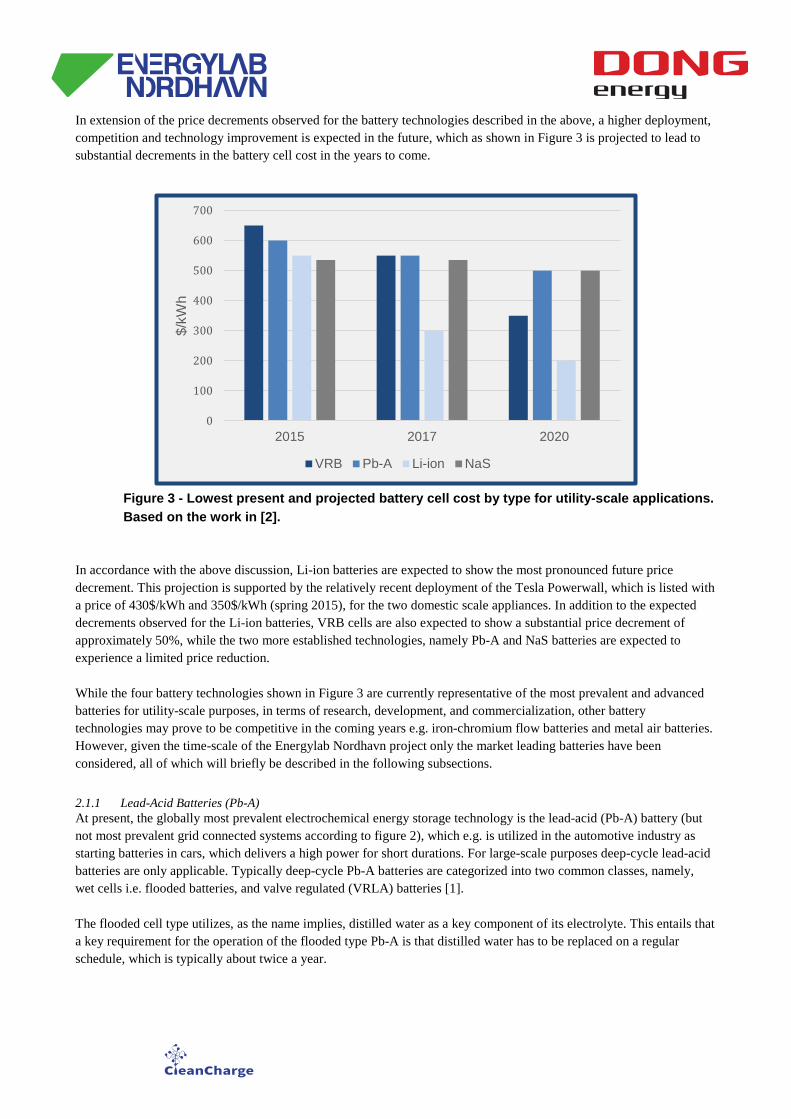
In extension of the price decrements observed for the battery technologies described in the above, a higher deployment, competition and technology improvement is expected in the future, which as shown in Figure 3 is projected to lead to substantial decrements in the battery cell cost in the years to come.
In accordance with the above discussion, Li-ion batteries are expected to show the most pronounced future price decrement. This projection is supported by the relatively recent deployment of the Tesla Powerwall, which is listed with a price of 430$/kWh and 350$/kWh (spring 2015), for the two domestic scale appliances. In addition to the expected decrements observed for the Li-ion batteries, VRB cells are also expected to show a substantial price decrement of approximately 50%, while the two more established technologies, namely Pb-A and NaS batteries are expected to experience a limited price reduction. While the four battery technologies shown in Figure 3 are currently representative of the most prevalent and advanced batteries for utility-scale purposes, in terms of research, development, and commercialization, other battery technologies may prove to be competitive in the coming years e.g. iron-chromium flow batteries and metal air batteries. However, given the time-scale of the Energylab Nordhavn project only the market leading batteries have been considered, all of which will briefly be described in the following subsections.
2.1.1 Lead-Acid Batteries (Pb-A) At present, the globally most prevalent electrochemical energy storage technology is the lead-acid (Pb-A) battery (but not most prevalent grid connected systems according to figure 2), which e.g. is utilized in the automotive industry as starting batteries in cars, which delivers a high power for short durations. For large-scale purposes deep-cycle lead-acid batteries are only applicable. Typically deep-cycle Pb-A batteries are categorized into two common classes, namely, wet cells i.e. flooded batteries, and valve regulated (VRLA) batteries [1]. The flooded cell type utilizes, as the name implies, distilled water as a key component of its electrolyte. This entails that a key requirement for the operation of the flooded type Pb-A is that distilled water has to be replaced on a regular schedule, which is typically about twice a year.
0
100
200
300
400
500
600
700
2015 2017 2020
$/kW
h
VRB Pb-A Li-ion NaS
Figure 3 - Lowest present and projected battery cell cost by type for utility-scale applications. Based on the work in [2].

Furthermore, the flooded type also requires that the battery is oriented upright in order to prevent the any spilling of the electrolytes. VRLA batteries require less maintenance and are less sensitive to orientations. The primary distinctions between these types of batteries are the initial capital costs, where wet cells are less expensive, but require frequent maintenance, where the VRLA batteries requires monthly maintenance to check and refill the battery with distilled water in case the water levels drop below the plates. In Figure 4 a schematic illustration of a lead-acid battery cell is illustrated.
As seen in Figure 4 the lead-acid battery cell consists of a positive electrode of lead dioxide (PbO2) and a negative electrode of sponge lead, which is separated by a micro-porous material and immersed in an aqueous sulfuric acid electrolyte; which is contained in a plastic case. The main advantages of lead-acid, Pb-A batteries are the mature, well investigated state of the technology and its low cost. Cycle efficiencies are in the order of 80-90%, and self-discharge of the batteries are relatively low (2% per month). Whereas, some of the disadvantages of the technology are the low energy density and limited power capacity of the batteries as it decreases when the batteries are discharged at high power. Furthermore, given that both the degradation of Pb-A batteries is relatively susceptible to full discharges, and the low energy density, entails that the technology is less attractive for energy management. This is also reflected in the choice of applications of Pb-A batteries, where the typical services provided by the technology are power reliability and quality, e.g. in terms of emergency power supply, stand-alone systems with PV, and for levelling of the output fluctuations from wind power. Existing Large-Scale Applications As an example of an existing large-scale application utilizing a Pb-A system, the Notrees Wind Storage Demonstration Project [4] located in western Texas in the US utilizes a 36MW/24MWh BESS, making it the second largest battery system in the world (in terms of power rating). The storage system is utilized in connection with a 153MW wind farm, and is located at the substation and connected to the distribution side. The goal of the project is to demonstrate the potential of utilizing energy storage technologies to help wind power systems address intermittency issues, and furthermore to provide regulation services in the ERCOT market e.g. frequency regulation including nonspinning- and
Figure 4 - Schematic illustration of a lead-acid battery cell. A positive electrode of lead dioxide (PbO2) and a negative electrode of sponge lead are separated by a micro-porous material and immersed in an aqueous sulfuric acid electrolyte.
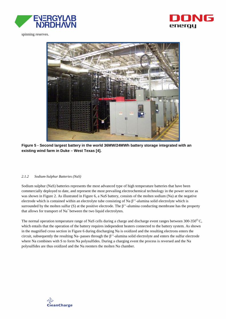
spinning reserves.
Figure 5 - Second largest battery in the world 36MW/24MWh battery storage integrated with an existing wind farm in Duke – West Texas [4].
2.1.2 Sodium-Sulphur Batteries (NaS) Sodium sulphur (NaS) batteries represents the most advanced type of high temperature batteries that have been commercially deployed to date, and represent the most prevailing electrochemical technology in the power sector as was shown in Figure 2. As illustrated in Figure 6, a NaS battery, consists of the molten sodium (Na) at the negative electrode which is contained within an electrolyte tube consisting of Na β’’-alumina solid electrolyte which is surrounded by the molten sulfur (S) at the positive electrode. The β’’-alumina conducting membrane has the property that allows for transport of Na+ between the two liquid electrolytes. The normal operation temperature range of NaS cells during a charge and discharge event ranges between 300-350O C, which entails that the operation of the battery requires independent heaters connected to the battery system. As shown in the magnified cross section in Figure 6 during discharging Na is oxidized and the resulting electrons enters the circuit, subsequently the resulting Na+ passes through the β’’-alumina solid electrolyte and enters the sulfur electrode where Na combines with S to form Na polysulfides. During a charging event the process is reversed and the Na polysulfides are thus oxidized and the Na reenters the molten Na chamber.
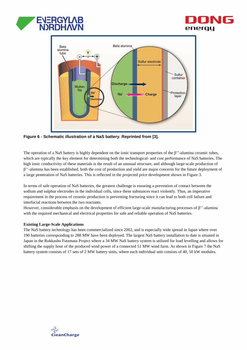
Figure 6 - Schematic illustration of a NaS battery. Reprinted from [3].
The operation of a NaS battery is highly dependent on the ionic transport properties of the β’’-alumina ceramic tubes, which are typically the key element for determining both the technological- and cost performance of NaS batteries. The high ionic conductivity of these materials is the result of an unusual structure, and although large-scale production of β’’-alumina has been established, both the cost of production and yield are major concerns for the future deployment of a large penetration of NaS batteries. This is reflected in the projected price development shown in Figure 3. In terms of safe operation of NaS batteries, the greatest challenge is ensuring a prevention of contact between the sodium and sulphur electrodes in the individual cells, since these substances react violently. Thus, an imperative requirement in the process of ceramic production is preventing fracturing since it can lead to both cell failure and interfacial reactions between the two reactants. However, considerable emphasis on the development of efficient large-scale manufacturing processes of β’’-alumina with the required mechanical and electrical properties for safe and reliable operation of NaS batteries. Existing Large-Scale Applications The NaS battery technology has been commercialized since 2002, and is especially wide spread in Japan where over 190 batteries corresponding to 288 MW have been deployed. The largest NaS battery installation to date is situated in Japan in the Rokkasho Futamata Project where a 34 MW NaS battery system is utilized for load levelling and allows for shifting the supply hour of the produced wind power of a connected 51 MW wind farm. As shown in Figure 7 the NaS battery system consists of 17 sets of 2 MW battery units, where each individual unit consists of 40, 50 kW modules.
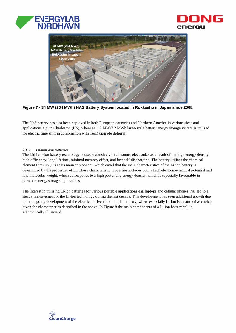
Figure 7 - 34 MW (204 MWh) NAS Battery System located in Rokkasho in Japan since 2008.
The NaS battery has also been deployed in both European countries and Northern America in various sizes and applications e.g. in Charleston (US), where an 1.2 MW/7.2 MWh large-scale battery energy storage system is utilized for electric time shift in combination with T&D upgrade deferral.
2.1.3 Lithium-ion Batteries The Lithium-Ion battery technology is used extensively in consumer electronics as a result of the high energy density, high efficiency, long lifetime, minimal memory effect, and low self-discharging. The battery utilizes the chemical element Lithium (Li) as its main component, which entail that the main characteristics of the Li-ion battery is determined by the properties of Li. These characteristic properties includes both a high electromechanical potential and low molecular weight, which corresponds to a high power and energy density, which is especially favourable in portable energy storage applications. The interest in utilizing Li-ion batteries for various portable applications e.g. laptops and cellular phones, has led to a steady improvement of the Li-ion technology during the last decade. This development has seen additional growth due to the ongoing development of the electrical driven automobile industry, where especially Li-ion is an attractive choice, given the characteristics described in the above. In Figure 8 the main components of a Li-ion battery cell is schematically illustrated.
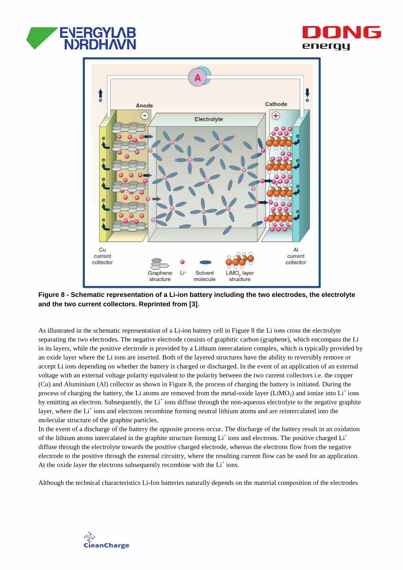
Figure 8 - Schematic representation of a Li-ion battery including the two electrodes, the electrolyte and the two current collectors. Reprinted from [3].
As illustrated in the schematic representation of a Li-ion battery cell in Figure 8 the Li ions cross the electrolyte separating the two electrodes. The negative electrode consists of graphitic carbon (graphene), which encompass the Li in its layers, while the positive electrode is provided by a Lithium intercalation complex, which is typically provided by an oxide layer where the Li ions are inserted. Both of the layered structures have the ability to reversibly remove or accept Li ions depending on whether the battery is charged or discharged. In the event of an application of an external voltage with an external voltage polarity equivalent to the polarity between the two current collectors i.e. the copper (Cu) and Aluminium (Al) collector as shown in Figure 8, the process of charging the battery is initiated. During the process of charging the battery, the Li atoms are removed from the metal-oxide layer (LiMO2) and ionize into Li+ ions by emitting an electron. Subsequently, the Li+ ions diffuse through the non-aqueous electrolyte to the negative graphite layer, where the Li+ ions and electrons recombine forming neutral lithium atoms and are reintercalated into the molecular structure of the graphite particles. In the event of a discharge of the battery the opposite process occur. The discharge of the battery result in an oxidation of the lithium atoms intercalated in the graphite structure forming Li+ ions and electrons. The positive charged Li+ diffuse through the electrolyte towards the positive charged electrode, whereas the electrons flow from the negative electrode to the positive through the external circuitry, where the resulting current flow can be used for an application. At the oxide layer the electrons subsequently recombine with the Li+ ions. Although the technical characteristics Li-Ion batteries naturally depends on the material composition of the electrodes
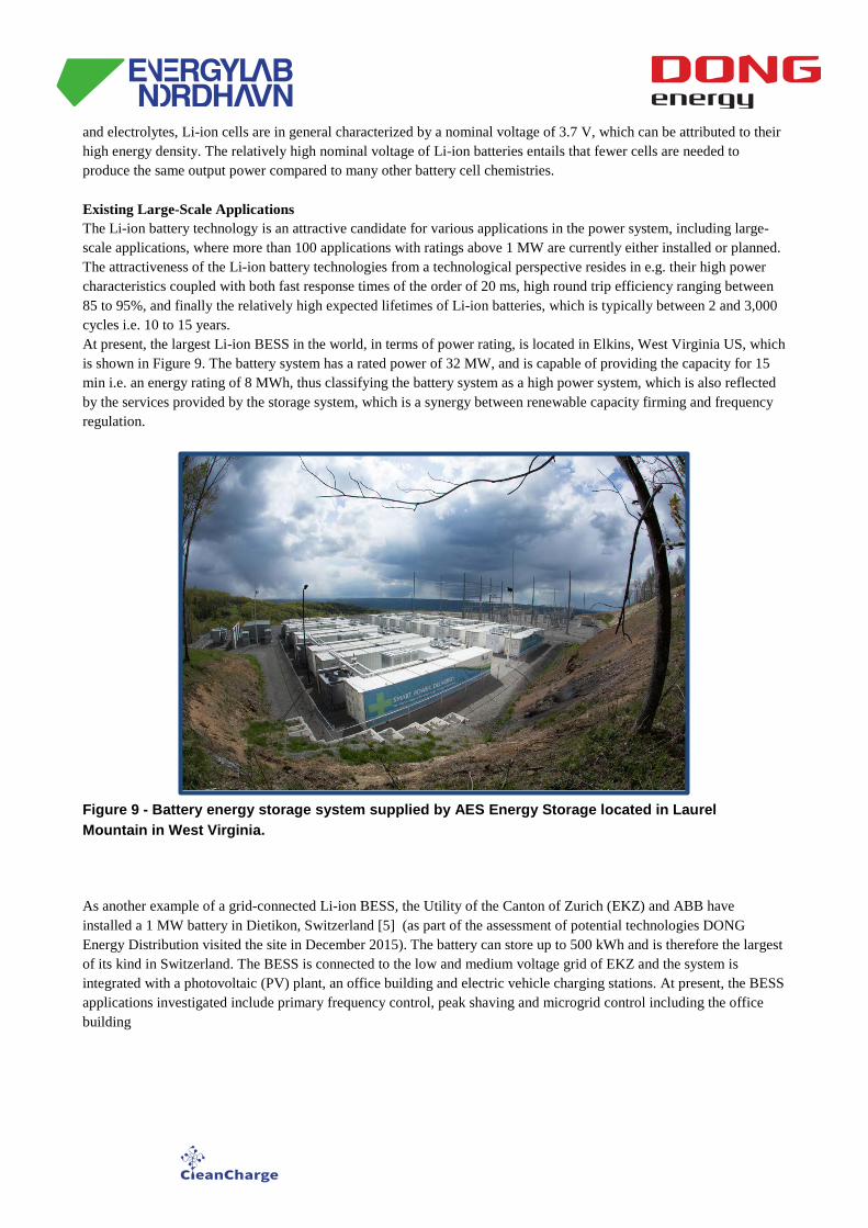
and electrolytes, Li-ion cells are in general characterized by a nominal voltage of 3.7 V, which can be attributed to their high energy density. The relatively high nominal voltage of Li-ion batteries entails that fewer cells are needed to produce the same output power compared to many other battery cell chemistries. Existing Large-Scale Applications The Li-ion battery technology is an attractive candidate for various applications in the power system, including large-scale applications, where more than 100 applications with ratings above 1 MW are currently either installed or planned. The attractiveness of the Li-ion battery technologies from a technological perspective resides in e.g. their high power characteristics coupled with both fast response times of the order of 20 ms, high round trip efficiency ranging between 85 to 95%, and finally the relatively high expected lifetimes of Li-ion batteries, which is typically between 2 and 3,000 cycles i.e. 10 to 15 years. At present, the largest Li-ion BESS in the world, in terms of power rating, is located in Elkins, West Virginia US, which is shown in Figure 9. The battery system has a rated power of 32 MW, and is capable of providing the capacity for 15 min i.e. an energy rating of 8 MWh, thus classifying the battery system as a high power system, which is also reflected by the services provided by the storage system, which is a synergy between renewable capacity firming and frequency regulation.
Figure 9 - Battery energy storage system supplied by AES Energy Storage located in Laurel Mountain in West Virginia.
As another example of a grid-connected Li-ion BESS, the Utility of the Canton of Zurich (EKZ) and ABB have installed a 1 MW battery in Dietikon, Switzerland [5] (as part of the assessment of potential technologies DONG Energy Distribution visited the site in December 2015). The battery can store up to 500 kWh and is therefore the largest of its kind in Switzerland. The BESS is connected to the low and medium voltage grid of EKZ and the system is integrated with a photovoltaic (PV) plant, an office building and electric vehicle charging stations. At present, the BESS applications investigated include primary frequency control, peak shaving and microgrid control including the office building
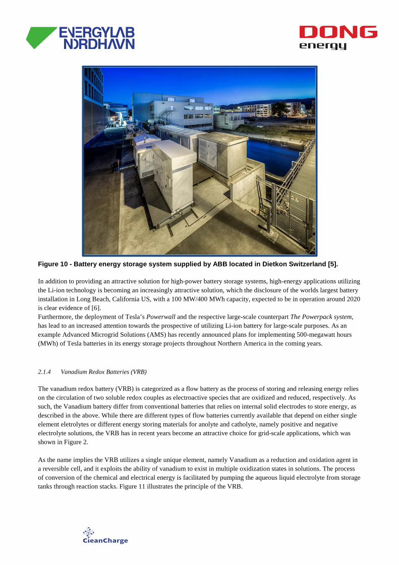
Figure 10 - Battery energy storage system supplied by ABB located in Dietkon Switzerland [5].
In addition to providing an attractive solution for high-power battery storage systems, high-energy applications utilizing the Li-ion technology is becoming an increasingly attractive solution, which the disclosure of the worlds largest battery installation in Long Beach, California US, with a 100 MW/400 MWh capacity, expected to be in operation around 2020 is clear evidence of [6]. Furthermore, the deployment of Tesla’s Powerwall and the respective large-scale counterpart The Powerpack system, has lead to an increased attention towards the prospective of utilizing Li-ion battery for large-scale purposes. As an example Advanced Microgrid Solutions (AMS) has recently announced plans for implementing 500-megawatt hours (MWh) of Tesla batteries in its energy storage projects throughout Northern America in the coming years. 2.1.4 Vanadium Redox Batteries (VRB) The vanadium redox battery (VRB) is categorized as a flow battery as the process of storing and releasing energy relies on the circulation of two soluble redox couples as electroactive species that are oxidized and reduced, respectively. As such, the Vanadium battery differ from conventional batteries that relies on internal solid electrodes to store energy, as described in the above. While there are different types of flow batteries currently available that depend on either single element eletrolytes or different energy storing materials for anolyte and catholyte, namely positive and negative electrolyte solutions, the VRB has in recent years become an attractive choice for grid-scale applications, which was shown in Figure 2. As the name implies the VRB utilizes a single unique element, namely Vanadium as a reduction and oxidation agent in a reversible cell, and it exploits the ability of vanadium to exist in multiple oxidization states in solutions. The process of conversion of the chemical and electrical energy is facilitated by pumping the aqueous liquid electrolyte from storage tanks through reaction stacks. Figure 11 illustrates the principle of the VRB.
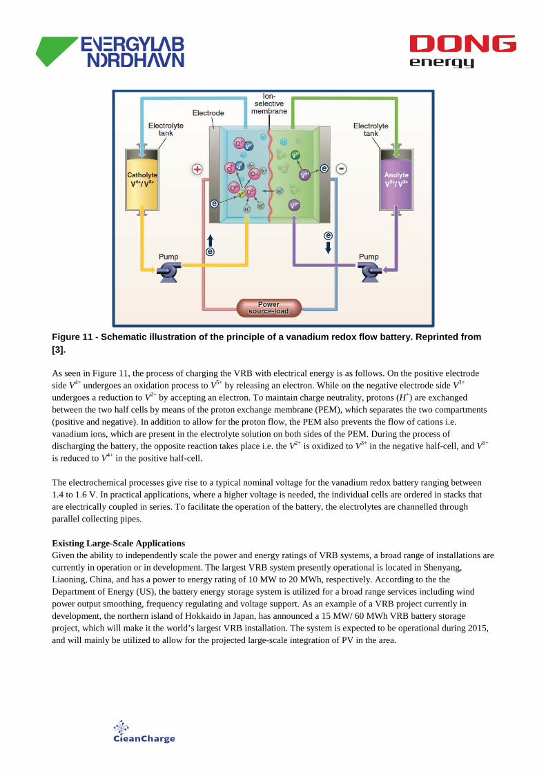
Figure 11 - Schematic illustration of the principle of a vanadium redox flow battery. Reprinted from [3].
As seen in Figure 11, the process of charging the VRB with electrical energy is as follows. On the positive electrode side V4+ undergoes an oxidation process to V5+ by releasing an electron. While on the negative electrode side V3+ undergoes a reduction to V2+ by accepting an electron. To maintain charge neutrality, protons (H+) are exchanged between the two half cells by means of the proton exchange membrane (PEM), which separates the two compartments (positive and negative). In addition to allow for the proton flow, the PEM also prevents the flow of cations i.e. vanadium ions, which are present in the electrolyte solution on both sides of the PEM. During the process of discharging the battery, the opposite reaction takes place i.e. the V2+ is oxidized to V3+ in the negative half-cell, and V5+ is reduced to V4+ in the positive half-cell. The electrochemical processes give rise to a typical nominal voltage for the vanadium redox battery ranging between 1.4 to 1.6 V. In practical applications, where a higher voltage is needed, the individual cells are ordered in stacks that are electrically coupled in series. To facilitate the operation of the battery, the electrolytes are channelled through parallel collecting pipes.
Existing Large-Scale Applications Given the ability to independently scale the power and energy ratings of VRB systems, a broad range of installations are currently in operation or in development. The largest VRB system presently operational is located in Shenyang, Liaoning, China, and has a power to energy rating of 10 MW to 20 MWh, respectively. According to the the Department of Energy (US), the battery energy storage system is utilized for a broad range services including wind power output smoothing, frequency regulating and voltage support. As an example of a VRB project currently in development, the northern island of Hokkaido in Japan, has announced a 15 MW/ 60 MWh VRB battery storage project, which will make it the world’s largest VRB installation. The system is expected to be operational during 2015, and will mainly be utilized to allow for the projected large-scale integration of PV in the area.
3. Conclusion
This document presented the preliminary assessment of battery types with emphasis on the leading market BESS. From the assessment is has been found that at present the most attractive solution is the Li-ion BESS, and Grid Strategy has up until this point gathered non-binding price estimates from a range of suppliers.
4. References [1] Department of Energy (US). Electricity storage handbook in collaboration with nreca. Technical report, 2015. [2] International Renewable Energy Agency (IRENA). Battery storage for renewables: Market status and technology outlook. Technical report, 2015. [3] Bruce Dunn et al. Electrical energy storage for the grid: A battery of choices. Science, 334(928), 2011. [4] Duke Energy. www.duke-energy.com/commercial-renewables/notrees-windpower.asp, 2015. [5] Michael Koller, Theodor Borsche, Andreas Ulbig, Göran Andersson, “Review of grid applications with the Zurich 1 MW battery energystorage system”, Electric Power Systems Research 120 (2015) 128–135. [6] Eric Wesoff, “The world's biggest battery is coming to California”, GreenTech Media, November 12, 2014.