Deign and epeimen of eneg‑aing ate injecion pmp
9
Vol.:(0123456789) 1 3 Journal of Petroleum Exploration and Production Technology (2020) 10:2127–2135 https://doi.org/10.1007/s13202-020-00860-1 ORIGINAL PAPER - PRODUCTION ENGINEERING Design and experiment of energy‑saving water injection pump Junyou Zhao 1 · Yafei Dong 1 · Jianwei Fu 2 · Luhao Zhao 3 · Yaning Zhang 1 Received: 12 November 2019 / Accepted: 17 February 2020 / Published online: 24 February 2020 © The Author(s) 2020 Abstract An energy-saving water injection pump aimed at high-energy consumption and low efficiency of the traditional water injec- tion pump in the later stages of oilfield exploitation is proposed. The hydraulic pump is used as the main power source to control the movement of the piston through the mechanical reversing valve, thereby driving the plunger to move left and right, supercharging the water in the plunger cylinder. First, the structural parameters of the energy-saving water injection pump were determined. Then, dynamic analysis of the pump parts was carried out. The finite element simulation of the piston cylinder and the plunger cylinder showed that the structural strength meets the requirements. The hydraulic system dynamic simulation showed that the output pressure can reach the predetermined pressure. Finally, a field test was carried out in the Jiangsu Oilfield. The results show that the device can meet the water injection requirements of the oilfield. Keywords Oilfield water injection · Supercharging · Structural design · Energy saving · Field test Introduction During the production phase of oil fields, mining difficulties occurred while the production pressure dropped down with time. Therefore, it was critical to replenish the consumed pressure artificially (Nanda et al. 2011). Through oilfield water injection, the energy of the oilfield can be recovered, the oil production will be stable, and the final recovery fac- tor of the oil field can be improved (Mahmoud et al. 2017; Graff and Nielsen 1991; Zhang 2000). The water injection capacity is related to the nature of the formation proper- ties. Before water injection, the geologists and oil produc- tion experts should first calculate the daily water injection volume according to the geological conditions of the cor- responding oil wells (Yu et al. 2017). The injection pres- sure required by different oilfields and production zones is variable. If uniform water injection pipe-network pres- sure is adopted, it cannot meet the requirements of several high-pressure injection wells under the premise that most pressure requirements of injection wells are matched. If the pressure of the whole pipe network is increased, the pres- sure reduction equipment should be installed at the low- pressure water injection wellhead, which results in low uti- lization of energy (Chappell 2006; Zhang and Zuo 2007; Wang et al. 2014). The installation of piston water injection booster pumps at the injection wellheads is one of the effec- tive means to improve the efficiency of the water injection system (Rehman and Meribout 2012; Liu and Liao 1999; Smolyanskii et al. 1998). The piston water injection booster pump uses the pressure of the water injection pipe network as the suction pressure of the pump and injects water into the high-pressure well after pressurization (Ling et al.2008; Vance and Kent 2001; Liu et al. 2012). However, the tra- ditional booster water pump consumes a large amount of power, which greatly increases the production cost of crude oil and causes wastage of power resources (Zhou and Yuan 2003). The energy-saving water injection pump proposed * Yafei Dong fl[email protected] Junyou Zhao [email protected] Jianwei Fu [email protected] Luhao Zhao [email protected] Yaning Zhang [email protected] 1 College of Mechanical and Electrical Engineering, China University of Petroleum (Huadong), Qingdao, Shandong, China 2 Hisense Group Co., Ltd., Qingdao, Shandong, China 3 Hangzhou Hikvision Digital Technology Co., Ltd., Hangzhou, Zhejiang, China
Transcript of Deign and epeimen of eneg‑aing ate injecion pmp

Vol.:(0123456789)1 3
Journal of Petroleum Exploration and Production Technology (2020) 10:2127–2135 https://doi.org/10.1007/s13202-020-00860-1
ORIGINAL PAPER - PRODUCTION ENGINEERING
Design and experiment of energy‑saving water injection pump
Junyou Zhao1 · Yafei Dong1 · Jianwei Fu2 · Luhao Zhao3 · Yaning Zhang1
Received: 12 November 2019 / Accepted: 17 February 2020 / Published online: 24 February 2020 © The Author(s) 2020
AbstractAn energy-saving water injection pump aimed at high-energy consumption and low efficiency of the traditional water injec-tion pump in the later stages of oilfield exploitation is proposed. The hydraulic pump is used as the main power source to control the movement of the piston through the mechanical reversing valve, thereby driving the plunger to move left and right, supercharging the water in the plunger cylinder. First, the structural parameters of the energy-saving water injection pump were determined. Then, dynamic analysis of the pump parts was carried out. The finite element simulation of the piston cylinder and the plunger cylinder showed that the structural strength meets the requirements. The hydraulic system dynamic simulation showed that the output pressure can reach the predetermined pressure. Finally, a field test was carried out in the Jiangsu Oilfield. The results show that the device can meet the water injection requirements of the oilfield.
Keywords Oilfield water injection · Supercharging · Structural design · Energy saving · Field test
Introduction
During the production phase of oil fields, mining difficulties occurred while the production pressure dropped down with time. Therefore, it was critical to replenish the consumed pressure artificially (Nanda et al. 2011). Through oilfield water injection, the energy of the oilfield can be recovered, the oil production will be stable, and the final recovery fac-tor of the oil field can be improved (Mahmoud et al. 2017; Graff and Nielsen 1991; Zhang 2000). The water injection
capacity is related to the nature of the formation proper-ties. Before water injection, the geologists and oil produc-tion experts should first calculate the daily water injection volume according to the geological conditions of the cor-responding oil wells (Yu et al. 2017). The injection pres-sure required by different oilfields and production zones is variable. If uniform water injection pipe-network pres-sure is adopted, it cannot meet the requirements of several high-pressure injection wells under the premise that most pressure requirements of injection wells are matched. If the pressure of the whole pipe network is increased, the pres-sure reduction equipment should be installed at the low-pressure water injection wellhead, which results in low uti-lization of energy (Chappell 2006; Zhang and Zuo 2007; Wang et al. 2014). The installation of piston water injection booster pumps at the injection wellheads is one of the effec-tive means to improve the efficiency of the water injection system (Rehman and Meribout 2012; Liu and Liao 1999; Smolyanskii et al. 1998). The piston water injection booster pump uses the pressure of the water injection pipe network as the suction pressure of the pump and injects water into the high-pressure well after pressurization (Ling et al.2008; Vance and Kent 2001; Liu et al. 2012). However, the tra-ditional booster water pump consumes a large amount of power, which greatly increases the production cost of crude oil and causes wastage of power resources (Zhou and Yuan 2003). The energy-saving water injection pump proposed
* Yafei Dong [email protected]
Junyou Zhao [email protected]
Jianwei Fu [email protected]
Luhao Zhao [email protected]
Yaning Zhang [email protected]
1 College of Mechanical and Electrical Engineering, China University of Petroleum (Huadong), Qingdao, Shandong, China
2 Hisense Group Co., Ltd., Qingdao, Shandong, China3 Hangzhou Hikvision Digital Technology Co., Ltd.,
Hangzhou, Zhejiang, China
2128 Journal of Petroleum Exploration and Production Technology (2020) 10:2127–2135
1 3
in this study was developed in view of the water injection booster device defect. The field experiment showed that the energy consumption was greatly reduced, the oil displace-ment effect was improved, and the recovery rate of the oil field was increased.
Overall design and working principle
Process flow
The energy-saving water injection pump is a pressure-increase device. It can further increase the water injection pressure on the high-pressure wellhead based on the pressure of the water injection main line in the water injection field. The input of the device is directly connected to the main line of water injection. Under the action of the hydraulic pump, the hydraulic oil pushes the piston to perform secondary supercharging of the water flow. Then, the pressurized high-pressure water is injected into the high-pressure wellhead. The pressure of the water injection main line only needs to meet the required pressure of the low-pressure wellhead. The entire process flow is shown in Fig. 1.
Design of whole structure
The energy-saving water injection pump is mainly divided into two parts: mechanical reversing valve and double-acting plunger pump. Figure 2 shows the overall structure.
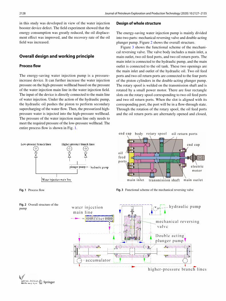
Figure 3 shows the functional scheme of the mechani-cal reversing valve. The valve body includes a main inlet, a main outlet, two oil feed ports, and two oil return ports. The main inlet is connected to the hydraulic pump, and the main outlet is connected to the oil tank. These two openings are the main inlet and outlet of the hydraulic oil. Two oil feed ports and two oil return ports are connected to the four ports of the piston cylinders in the double-acting plunger pump. The rotary spool is welded on the transmission shaft and is rotated by a small power motor. There are four rectangle slots on the rotary spool corresponding to two oil feed ports and two oil return ports. When the slot is aligned with its corresponding port, the port will be in a flow-through state. Through the rotation of the rotary spool, the oil feed ports and the oil return ports are alternately opened and closed,
Fig. 1 Process flow
Fig. 2 Overall structure of the pump
Fig. 3 Functional scheme of the mechanical reversing valve

2129Journal of Petroleum Exploration and Production Technology (2020) 10:2127–2135
1 3
which not only completes the reversing action of the double-acting plunger pump, but also helps the hydraulic oil flow smoothly through the valve body. This effectively prevents the liquid impact and increases the stability of its operation. Size and internal structure of the mechanical reversing valve are shown in Fig. 4.
The functional scheme of the double-acting plunger pump is shown in Fig. 5. The piston cylinder is in the middle of the pump, and the left and right plunger cylinders are on its sides. There are two oil feed ports and two oil return ports on the left and right side of the piston cylinder that are connected to the oil feed port and the oil return port of the mechanical reversing valve, respectively. The plunger cylin-der has a water inlet and outlet. The water inlet is connected to the water injection main line, and a filter is arranged to prevent the impurities in the main line from wearing the cylinder, valves, and seals. The water outlet is connected to the high-pressure branch lines. Accumulators are installed between them to store energy and stabilize the pressure. The size and internal structure of the double-acting plunger pump are shown in Fig. 6.
Working principle
In the energy-saving water injection pump, the booster sys-tem uses a double-acting plunger pump. The movement of the piston is divided into two strokes: left and right stroke. The switching of the stroke is controlled by the mechanical reversing valve. The right stroke is taken as an example to introduce the working principle. The water injection main line and the left and right plunger cylinders are in a one-way communication state. At the beginning of the right stroke, the hydraulic oil is pressurized by the hydraulic pump and then flows through the reversing valve, injected into the pis-ton cylinder to push the piston from left to right, thereby driving the plunger to move synchronously. At the same time, the water in the main line flows from the inlet into
the left plunger cylinder. The pressure from the main line simultaneously pushes the plunger to the right, pressuriz-ing the water in the right plunger cylinder. Then, the high-pressure water is injected into the high-pressure wellhead through the accumulator. The hydraulic oil in the right side of the piston cylinder flows back to the oil tank through the mechanical reversing valve. The direction of piston move-ment is controlled by the rotation of the rotary spool in the mechanical reversing valve. When the spool is rotated by 180°, the piston moves in the opposite direction, and the left stroke begins.
Calculation and simulation
Setting initial parameters
The Jiangsu Oilfield is a complex small intermittent block reservoir. Water injection is the main measure to achieve sta-ble production in the oil field. Data from the injection wells after on-site investigation are shown in Table 1. According to Table 1, the daily injection flow rate of No. Sha 19–50 and No. Sha 19–51 is less than the rated injection flow rate. These two wellheads are short of injection.
The initial parameters of the energy-saving water injection pump are set according to the water injection requirements of
Fig. 4 Size and internal structure of the mechanical reversing valve
Fig. 5 Functional scheme of the double-acting plunger pump
Fig. 6 Size and internal structure of the double-acting plunger pump

2130 Journal of Petroleum Exploration and Production Technology (2020) 10:2127–2135
1 3
the Jiangsu Oilfield, as shown in Table 2. Other key parameters are calculated according to these parameters.
Pressure calculation and strength check
According to Table 1, the pressure of the water injection main-line in the field is 25MPa , while the injection pressure of the high-pressure well is required to be pressurized to 29 MPa for normal production. The mechanical model is built according to the water injection site data, as shown in Fig. 7.
According to the Pascal principle, the pressure applied to the stationary liquid in a closed vessel is equally transferred to every point in the liquid (Zang 2009), establishing the equilibrium equation as follows:
where p0 is the oil pressure in the piston cylinder, which is the output pressure of the hydraulic pump, p1 is the pressure
(1)p1A2 + p0A1 = p2A1 + p3A2
(2)A1 =�
4
(
D2 − d21
)
(3)A2 =�
4d2,
of the water injection main line, p2 is the oil discharge pres-sure, p3 is the injection pressure of the high-pressure well-head, A1 is the cross-sectional area of the effective face of the piston, A2 is the cross-sectional area of the plunger, D is the diameter of the piston, d1 is the diameter of the piston rod, and d is the diameter of the plunger. Equation 4 can be obtained by combining Eqs. 1–3.
The oil in the piston cylinder is directly discharged into the oil tank; hence, p2 = 0 MPa . Assuming that the output pressure of the hydraulic pump is equal to its rated pressure, substituting the already set structural parameters and the on-site pressure parameters into Eq. 4, the rated pressure of the hydraulic pump is p0 = 2.37 MPa.
To check whether the maximum stress on the plunger cylinder and the piston cylinder is within the allowable stress range under the specified pressure, ANSYS simulation is performed using static analysis and displacement calculation as algorithms, and the theoretical basis is the principle of virtual displacement and the principle of minimum potential energy. The static balance formula is as follows:
where Ω is the force area; Γ� is the boundary of the surface force; �u is the virtual displacement; and �� is the virtual strain. First, the model is built in Solidworks and is imported into ANSYS. Then, the inner surface pressure of the plunger cylinder is set as 29 MPa, the inner surface pressure of the piston cylinder as 2.37 MPa, the material as 20 Mn, and the yield strength as �s = 275MPa . Next, the material properties are set: the elastic modulus = 2.1 × 10¹¹ Pa and the Poisson ratio = 0.28. Finally, a fixed constraint is set on the lower sur-face of both the cylinders. After calculation, the equivalent stress and displacement were obtained.
As seen from Figs. 8 and 10, the displacement is asymmetric, since the lower surface is set as a fixed con-straint that restricts the deformation of the lower half of the plunger cylinder. Therefore, most of the deformation
(4)p0 = (p3 − p1)d2
D2 − d21
+ p2
(5)∫Ω
𝛿𝜀T𝜎dΩ = ∫Ω
𝛿uTF̄dΩ + ∫Γ𝜎
𝛿uTT̄dΓ,
Table 1 Injection wells data No. Mainline pres-sure ∕MPa
Oil pressure ∕MPa
Casing pres-sure ∕MPa
Daily injection flow rate ∕m3
Rated daily injec-tion flow rate ∕m3
Sha 19–46 25 23 25 109 100Sha 19–50 25 24 23 30 100Sha 19–51 25 24.5 24 27 100Sha 19–65 25 23.5 24.3 103 100Sha 19–72 25 23.7 24.9 106 100
Table 2 Initial parameters
Name Diam-eter of plunger ∕m
Diameter of piston rod ∕m
Diameter of piston ∕m
Strokes per sec-ond
Power of small power motor ∕kW
Param-eters
0.08 0.06 0.12 ≤ 0.5 1.1
Fig. 7 Mechanical model of the double-acting plunger pump

2131Journal of Petroleum Exploration and Production Technology (2020) 10:2127–2135
1 3
occurs in the upper half, and the lower surface has almost no deformation. The maximum displacement of the pis-ton cylinder occurs on the top of the inner surface, which is 0.919 × 10⁻² mm . The maximum displacement of the piston cylinder occurs on the junction of the inner surface and the end cap, which is 2 × 10⁻² mm . The deformations are both very small, and the structure of cylinders is not affected. Figures 9 and 11 are the equivalent stress dia-grams. It can be seen from Fig. 9 that the surfaces located on the left and right side of the piston are the main force receiving surfaces for the piston cylinder, and most of the inner surface bears a stress of about 18.7 MPa that is uniformly distributed. The piston in contact with the cyl-inder develops almost no stress due to the lack of hydrau-lic oil. However, severe stress concentration occurs at the intersection of piston cylinder and oil ports, and the maximum stress was 56.2 MPa. Therefore, some structural
optimization should be performed for this part to reduce the stress concentration when processing the prototype. It can be found from Fig. 10 that the stress on the inner surface of the plunger cylinder is more uniform than the piston cylinder, and the maximum stress is 66.6 MPa at the water inlet. Setting the safety factor n = 2.5 , then the allowable stress is as follows:
The calculated allowable stress is 110MPa , greater than 56.2 MPa and 66.6MPa . Thereby, the strength of both cyl-inders is satisfied (Fig. 11).
Calculation for flow and power of the hydraulic pump
The equation for calculating the daily injection amount of the high-pressure wellhead is as follows:
(6)[�] =�s
n
Fig. 8 Displacement variation of the piston cylinder
Fig. 9 Equivalent stress of the piston cylinder
Fig. 10 Displacement variation of the plunger cylinder
Fig. 11 Equivalent stress of the plunger cylinder

2132 Journal of Petroleum Exploration and Production Technology (2020) 10:2127–2135
1 3
where Q is the output flow of plunger cylinder that is equal to the rated daily injection flow rate of the high-pressure wellhead. According to Table 1, the total daily rated flow rate of the two short-injection high-pressure wellheads is 200m3 . The maximum volume loss efficiency is taken as 3.9% (Fan et al. 2010). Then, the daily rated flow rate is 208.1m3 , which is Q= 8.67m3∕h . L is the stroke, and N is the number of strokes per second of the piston.
Setting N = 0.5 , Q is substituted in Eq. 6 to arrive at the piston stroke of L= 0.48m . In this structure of the super-charging system, the movement state of the piston and the plunger is the same. It can be seen from Eq. 7 that when N and L are constants, the input flow of the piston cylinder Q0 is only proportional to the effective areas, as shown in Eq. 8:
Substituting the data and calculating, Q0 = 14.63m3∕h . If the influence of leakage or other factors is not considered, the input flow of the piston cylinder and the output flow of the hydraulic pump should be equal. The equation to calcu-late the power of the hydraulic pump is as follows:
where P0 is the output power of the hydraulic pump. Assum-ing that the total efficiency of the hydraulic pump � = 89% , then the rated power of the hydraulic pump is P= 10.82 kW , when the selected rated motor is 11 kW.
Calculation of acceleration time
The movement of the piston is divided into three phases: acceleration, uniform, and deceleration. The acceleration time affects the movement time of the entire stroke. If the acceleration time is too long, the supercharging would not be completed normally and the working stability of the hydrau-lic cylinder would be affected.
During the acceleration phase, the piston moves under the left and right differential pressure. Equation 11 can be established in the case of ignoring relatively small friction and according to Newton’s second law:
The injection pressure of the high-pressure wellhead p3 is linear with time t:
(7)Q =�
2⋅ d2LN,
(8)Q0
Q=
D2 − d21
d2
(9)P0 = p0Q0
(10)P =P0
�,
(11)p1A2 + p0A1 − p3A2 = Ma
Equation 13 is established during the movement of the piston:
where l is the displacement of the piston and a is accel-eration of piston. When the piston starts to move, that is, when t = 0 , p3(0) = 25 MPa . Assuming when t = t1 , the velocity reaches a uniform state, v(t1)= 0.46m/s , and p3(t1) = 29 MPa . According to the size of the piston, plunger, and rod, the equivalent mass of piston and load is calculated as M= 38.01 kg . Substituting these data in Eqs. 11–13, the acceleration time is t1= 1.75 × 10⁻³ s . The acceleration time is short, and the influence on the piston movement is negligible.
Hydraulic system dynamic simulation
After determining the structure and pressure parameters of the energy-saving water injection pump, the simulation was performed using the Amesim software. The software is based on Eqs. 14 and 15 (the cylinder flow continuity equa-tion) and Eq. 16 (the piston motion force balance equation). The following assumptions are made for the hydraulic sys-tem when establishing the mathematical model: The effects of pressure loss, pipe characteristics, and fluid quality in the pipeline are neglected; the volumetric elastic modulus of the oil is constant; the temperature of the oil remains unchanged; and the leakage inside and outside the hydraulic cylinder is laminar (Mohebbi et al. 2017).
where Ci is the inside cylinder leakage coefficient; Ce is the outside cylinder leakage coefficient; �e is the equivalent bulk modulus of oil; Vc is the cylinder working chamber volume; V0 is the cylinder working chamber initial volume; M is the equivalent mass of piston and load; Bp is the viscous friction coefficient of piston and load; K is the spring stiffness of load; and FL is the applied load force acting on the piston.
The required components were called in the mechanical library and hydraulic component library in the Amesim software, and the modeling of the energy-saving water injection pump was completed, as shown in Fig. 12. In
(12)p3(t) = kt + b
(13)a(t) =d2l
dt2,
(14)qL = A1
dL
dt+ CipL + Cep2 +
Vc
�e
dp2
dt
(15)Vc = V0 + A1L
(16)A1pL = Md2L
dt2+ Bp
dL
dt+ KL + FL

2133Journal of Petroleum Exploration and Production Technology (2020) 10:2127–2135
1 3
order to simplify the model, the mechanical reversing valve was replaced by a combination of a three-position four-way reversing valve and two two-position four-way reversing valves. Then, the structure and pressure param-eters for each component were set. The simulation time was set to 9 s , the simulation step to 0.1 s , and the starting
time to 1 s . The output pressure curve of the plunger cyl-inder is shown in Fig. 13.
It can be seen from Fig. 13 that after the device starts, the plunger cylinder B first pressurizes the water flow, where the output pressure is 29.3 MPa . After running for 2 s , the reversing valve controls the piston to reverse. Then, the plunger cylinder A pressurizes the water flow for the next 2 s . The working time of the whole cycle is 4 s . The simula-tion results are the same as the calculation results, which prove that the output pressure of the energy-saving water injection pump can reach the predetermined pressure. The water smoothly flows in the plunger, the pressure change is not steep, and the work condition is stable.
Pressure and field tests
Indoor pressure experiment
After completing the design of the energy-saving water injection pump, the parts were processed and finally assem-bled according to the drawings, as shown in Fig. 14. The indoor pressure experiment was performed in order to verify the strength, tightness, and reliability of the pressure-bear-ing components (Grigorescu and Navas 2012; Pitzer 1964). The energy-saving water injection pump was pressurized to 1.5 times the rated working pressure and was stabilized for 30 min to record the leakage of the device, as depicted in Fig. 15. The result showed that the device has no leak-age during the entire experiment, which proves that the structure of the device is tight, and the reliability meets the requirements.
Fig. 12 Simulation model
Fig. 13 Output pressure curve of the plunger cylinder

2134 Journal of Petroleum Exploration and Production Technology (2020) 10:2127–2135
1 3
Test at the oil field
The energy-saving water injection pump was applied at the water injection site of Jiangsu Oilfield. The pump at the water supply station for No. Sha 19–50 and No. Sha 19–51 was installed and pressurized from 4 to 29MPa . It was oper-ated continuously for a week and observed for work stability. The output pressure and power consumption were recorded every day. The records are presented in Table 3.
The data reveal that the device can meet the injection pressure and everyday water injection requirements of the two high-pressure wells and that the device is qualified for the injection task.
As illustrated in Table 3, the average daily elec-tric consumption of the device is 276.18 kW . Then, the electricity cost for a year will account for USD 10, 584 ( 0.105USD/kW ⋅ h ). This water injection site originally
used two traditional plunger pumps to inject water into the two high-pressure wells, each with a power of 45 kW . For comparison, the daily average power consumption of the previous pump measured before installing the energy-saving pump was 2077.73 kW . Then, the total annual electricity bill was accounted for more than USD 79,624 . In comparison, the energy-saving water injection pump can greatly reduce energy consumption and save electricity costs. The injection work continued after the field test, the performance index of the device was stable, the operation was reliable, and the energy saving was remarkable.
Conclusions
(a) The energy-saving water injection pump is used for oilfield-pressurized water injection. The key technol-ogy of the device is to control the left and right stroke of the piston through the mechanical reversing valve, thereby driving the plunger to raise the pressure. The whole device is relatively simple in structure and reli-able in operation.
(b) The structural parameters of the energy-saving water injection pump were determined. The finite element simulation of the piston cylinder and the plunger cyl-inder was performed, which shows that the structural strength meets the requirements. The hydraulic system dynamic simulation shows that the output pressure meets the water injection pressure.
(c) The energy-saving effect of the energy-saving water injection pump is remarkable. The injection can be realized without introducing a high-power source using only a small power motor with a 1.1 kW power to drive the mechanical directional control valve and a motor-driven hydraulic pump with a power of 11 kW . The daily electric consumption is only 276.18 kWh . Compared with the traditional electric plunger booster pump, the energy saving can reach more than 87%.
(d) The field test reveals that the energy-saving water injec-tion pump can meet the water injection requirements of
Fig. 14 Assembled pump
Fig. 15 Pressure test site
Table 3 Records of the injection test in field
Days Output pressure ∕MPa
Electric consumption per day ∕kW
Output flow per day ∕m3
1 29.6 286.53 206.22 29.7 278.17 201.53 28.9 264.32 199.64 29.1 271.02 205.15 29.4 279.79 208.96 30.3 282.53 212.37 29.1 270.91 203.9

2135Journal of Petroleum Exploration and Production Technology (2020) 10:2127–2135
1 3
the Jiangsu Oilfield. However, if it is to be promoted to a larger scale, the structural parameters of the water injection pump need to be redesigned for the corre-sponding oil fields to meet the requirements of various oilfield conditions.
Open Access This article is licensed under a Creative Commons Attri-bution 4.0 International License, which permits use, sharing, adapta-tion, distribution and reproduction in any medium or format, as long as you give appropriate credit to the original author(s) and the source, provide a link to the Creative Commons licence, and indicate if changes were made. The images or other third party material in this article are included in the article’s Creative Commons licence, unless indicated otherwise in a credit line to the material. If material is not included in the article’s Creative Commons licence and your intended use is not permitted by statutory regulation or exceeds the permitted use, you will need to obtain permission directly from the copyright holder. To view a copy of this licence, visit http://creat iveco mmons .org/licen ses/by/4.0/.
References
Chappell SD (2006) Waterflooding in deepwater environments. In: Offshore technology conference. Houston, Texas, USA
Fan FH, Zhong ZL, Shi JY (2010) Calculation and analysis of leakage flow rate of piston pairs of axial piston motor. Hydraul Pneum Seals 30(10):21–22
Graff OF, Nielsen N (1991) New water injection technology. In: Soci-ety of petroleum engineers. Aberdeen, United Kingdom
Grigorescu IC, Navas G (2012) Damage mechanisms in multistage pumps for water injection. In: NACE international. Salt Lake City, Utah
Ling ZF, Wang LJ, Li JS et al (2008) Research on horizontal injection and its application. Oil Drill Prod Technol 30(1):83–88. https ://doi.org/10.3969/j.issn.1000-7393.2008.01.022
Liu WZ, Liao CR (1999) Application status and development of water injection pump in Shengli oilfield. China Pet Mach 2:41–43
Liu YZ, Gu LH, Hao XJ (2012) Research for the application of well-head pressure drop data of injection well. Oil Drill Prod Technol b09:111–113
Mahmoud M, Elkatatny S, Abdelgawad K (2017) Using high- and low-salinity seawater injection to maintain the oil reservoir pressure
without damage. J Pet Explor Prod Technol 7:589–596. https ://doi.org/10.1007/s1320 2-016-0279-x
Mohebbi M, Aziz AA, Hamidi A et al (2017) Modeling of pressure line behavior of a common rail diesel engine due to injection and fuel variation. J Braz Soc Mech Sci Eng 39(3):661–669. https ://doi.org/10.1007/s4043 0-016-0573-z
Nanda R, Gupta S, Shukla A (2011) Experimental setup for perfor-mance characterization of a jet pump with varying angles of place-ment and depth. J Pet Explor Prod Technol 1:107–110. https ://doi.org/10.1007/s1320 2-011-0010-x
Pitzer SC (1964) Uses of transient pressure tests. In: Drilling and production practice, 1 January, New York. American Petroleum Institute, New York, USA
Rehman M, Meribout M (2012) Conventional versus electrical enhanced oil recovery: a review. J Pet Explor Prod Technol 2:169–179. https ://doi.org/10.1007/s1320 2-012-0035-9
Smolyanskii BG, Bakulin OV, Volkov OV (1998) New pumping equip-ment for oil product supply systems. Chem Pet Eng 34(6):397–399
Vance W, Kent G (2001) Pumping equipment for offshore deep water& marginal oilfields. World Pumps 419:14–17
Wang HY, Gao CQ, Liu LJ et al (2014) Practical application of plunger pump in oilfield water injection. Technol Enterp 5:204. https ://doi.org/10.3969/j.issn.11-3096/N.2014.05.187
Yu K, Li K, Li Q et al (2017) A method to calculate reasonable water injection rate for M oilfield. J Pet Explor Prod Technol 7(4):1003–1010. https ://doi.org/10.1007/s1320 2-017-0356-9
Zang KJ (2009) Hydraulic cylinder, 1st edn. Chemical Industry Press, Beijing
Zhang Q (2000) Principle and design of oil production engineer-ing, first edition, 1st edn. China University of Petroleum Press, Dongying
Zhang Z, Zuo F (2007) Research and application of underground pres-sure boosting and water injection techniques of inversion type submersible electric pump. Oil Drill Prod Technol 29(6):035–37. https ://doi.org/10.3969/j.issn.1000-7393.2007.06.013
Zhou XJ, Yuan J (2003) Design of the hydraulic supercharger for injec-tion well. Chin Hydraul Pneum 07:12–13
Publisher’s Note Springer Nature remains neutral with regard to jurisdictional claims in published maps and institutional affiliations.