DEFINITY Communications System Generic 3 …pdf.textfiles.com/manuals/TELECOM-A-E/DEFINITY G3...
321
555-230-894 Issue 1 September, 1995 DEFINITY ® Communications System Generic 3 Installation (For Single-Carrier Cabinets) Graphics © AT&T 1988
Transcript of DEFINITY Communications System Generic 3 …pdf.textfiles.com/manuals/TELECOM-A-E/DEFINITY G3...

555-230-894Issue 1September, 1995
DEFINITY® Communications System
Generic 3 Installation(For Single-Carrier Cabinets)
Graphics © AT&T 1988
Table of Contents

Contents
Issue 1 September 1995 iii
Table of Contents i
About This Book xv
■ This Book’s Organization xv
■ Other Books xvi
■ Trademarks xvii
1 Overview and Roadmap 1-1
■ System Reliability 1-1
Standard Reliability 1-2
High Reliability 1-2
Critical Reliability 1-2
■ DEFINITY System Installation Roadmap 1-3
Plan and Prepare the Site 1-3
Unpack the Cabinets 1-3
Install and Connect the Cabinets 1-3
Install Telecommunications Cabling 1-4
Install Generic 3 Management Terminal (G3-MT) 1-4
Activate the System 1-5
Test the System 1-5
Install and Wire Telephones and OtherEquipment 1-6
Administer the DEFINITY System According toCustomer Requirements 1-7
Test Telephones and Other Equipment 1-7
2 Plan and Prepare the Site 2-1
■ Check the Customer’s Order 2-1
■ Locate and Lay Out the Equipment Room 2-2

Contents
iv Issue 1 September 1995
Generic 3 Management Terminal (G3-MT) Requirements 2-2
Cross-Connect Fields 2-2
Space Requirements 2-2
Room Layout 2-2
Figure Notes: 2-3
Cable Slack Manager (Optional) Requirements 2-4
Tools Needed 2-4
Lay Out and Ensure Appropriate Power 2-6
Power Arrangements for AC Power 2-6
Power Arrangements for DC Power 2-7
■ Lay Out and Ensure Appropriate Grounding 2-8
Connect Coupled Bonding Conductor 2-8
■ Determine the Location of the Equipment Closets 2-9
■ Determine External Trunk Locations 2-9
■ Create a Provisioning Plan 2-9
3 Unpack the Cabinet 3-1
Unpack and Inspect for Damage 3-1
4 Install and Connect the Cabinets 4-1
■ Install Earthquake Mounting 4-2
■ Position and Stack the Cabinets 4-2
■ Connect System Cabinet Grounds 4-3
Figure Notes: 4-4
■ Connect Battery Leads 4-5
■ Connect Power 4-6
Connect AC Power 4-6
Connect DC Power 4-6
Figure Notes: 4-8 Connect Power Plant Ground 4-9 Figure Notes: 4-9 Connect Frame Ground 4-10 Figure Notes: 4-10 Connect DC Power Distribution Box Grounding 4-11
Contents
Issue 1 September 1995 v
Figure Notes: 4-11 Connect Single-Carrier Network Grounding 4-11 Figure Notes: 4-12 Coupled Bonding Conductor (CBC) 4-12 Figure Notes: 4-13 Connect DC Power to Networks 4-14 Connect AC Power to DC Power Cabinet 4-14 Test DC Power Plant 4-14
Connect Stand-by Power 4-14
■ Locate and Connect Time Division Multiplexing (TDM) Bus 4-15
Figure Notes: 4-16
■ Locate and Connect Inter-Cabinet Cables (ICC) 4-17
Figure Notes: 4-18
■ Install Fibre-Optic Cables 4-19
Fibre-Optic Cable Operation 4-19
Locate Fibre-Optic Cable Connections 4-19
General Rules and Recommendations forConnecting Fibre-Optic Cables 4-20
Figure Notes: 4-22 Figure Notes: 4-23
Raised Floor or Cable Slack Managers 4-23
Cable Connections 4-24
Standard Reliability Fibre-Optic Cable Connections 4-25
High Reliability Fibre-Optic Cable Connections 4-26
Critical Reliability Fibre-Optic Cable Connections 4-27
■ Verify Port Cabinet Address Plugs 4-29
■ Install Back Panels 4-30
■ Install Ground Plates 4-30
Figure Notes: 4-30
Install Ground Plates on Systems withEarthquake Protection 4-31
Install Ground Plates on Systems withoutEarthquake Protection 4-31
Figure Notes: 4-31
■ Install Cable Clamps 4-34
Figure Notes: 4-34
■ Install Front Plates 4-35

Contents
vi Issue 1 September 1995
Install Front Plates on Systems withEarthquake Protection 4-35
Install Cabinet Clip On Systems withoutEarthquake Protection 4-35
Figure Notes: 4-36
5 Install Telecommunications Cabling 5-1
■ Install the Cross-Connect Field 5-1
Typical Cross-Connect Field Using110-Type Hardware 5-1
Figure Notes: 5-2
Hardware Installation 5-3
■ Install Cable Slack Managers 5-3
■ Route Cables from Cabinet to Cross-Connect Field 5-3
Figure Notes: 5-5 Figure Notes: 5-6
■ Connect Control Carrier Outputs Cable 5-6
Label Cables 5-7
■ Install Trunk Cables Among Network Interface, Sneak Current Protector, and Switch Cabinet 5-7
6 Install Generic 3 Management Terminal 6-1
■ Generic 3 Management Terminal(G3-MT) Requirements 6-1
■ Connect Generic 3 Management Terminal (G3-MT) 6-2
Figure Notes: 6-4
■ Set Up G3 Management Terminal (G3-MT) 6-6
■ Remotely Connect Generic 3 Management Terminal (G3-MT) 6-7
Figure Notes: 6-7
7 Activate the System 7-1
■ Power Up Switch 7-2
Install Translation Flash-Memory Card 7-2

Contents
Issue 1 September 1995 vii
Power up AC-Powered Switch 7-3
Power up DC-Powered Switch 7-3
Verify Messages on Terminal 7-3
■ Introduction to Terminal Screens and Commands 7-4
Screens 7-4
Commands 7-5
Getting Help 7-5
■ Log in to the System 7-5
■ Set Required Country Options 7-6
■ Change Craft Password 7-9
■ Set Date and Time 7-11
■ Set System Maintenance Parameters 7-14
■ Save Translations 7-15
Logoff 7-17
8 Test the System 8-1
■ Check the System Status for Each Cabinet 8-1
■ Check Circuit Pack Configuration 8-4
■ Test Time Division Multiplexor (TDM)Bus in Processor Port Network (PPN) 8-9
■ Test Tone-Clock Boards 8-10
■ Test Switch Processing Element (SPE)Duplication Memory Shadowing Link 8-11
■ Test Duplicated Switch ProcessingElement (SPE) Interchange 8-12
■ Test Expansion Interface Boards 8-14
■ Test Time Division Multiplexer (TDM)for each Expansion Port Network (EPN) 8-15
■ Test Tone-Clock for each ExpansionPort Network (EPN) 8-16
■ Test Tone-Clock Interchange for eachExpansion Port Network (EPN) 8-17
■ Test Expansion Interface Exchange forEach Expansion Port Network (EPN) 8-17
■ Check Circuit Pack Configuration Again 8-19
■ Save Translations, if Required 8-20

Contents
viii Issue 1 September 1995
■ Re-install Front Doors 8-20
■ Next Steps 8-20
9 Install and Wire Telephones andOther Equipment 9-1
■ Telephone Connection Example 9-1
Connect Adjunct Power 9-3
■ Analog Station or 2-Wire Digital Station Example 9-5
■ Analog Tie Trunk Example 9-6
■ Digital Tie Trunk Example 9-9
■ Auxiliary Connector Outputs 9-10
■ APP Connector and Cable Diagrams (Pinout Charts) 9-15
■ Install Initialization and Administration System (INADS)Interface 9-21
Figure Notes: 9-21 Figure Notes: 9-22
■ Install Emergency Transfer Units andAssociated Telephones 9-23
Install the 808A Emergency Transfer Panel 9-23
■ Install External Ringing 9-24
Requirements 9-24
Installation 9-24
Figure Notes: 9-25
■ Install Queue Warning Indicator 9-25
Requirements 9-25
Installation 9-26
■ Install the 1145B1 Power Supply 9-26
Wall-Mounting Plates 9-27
Figure Notes: 9-28
Mount the 1145B1 Power Supply 9-29
Figure Notes: 9-29
Mount the 1146B1 Power Distribution Unit 9-30
Battery Mounting/Wiring 9-30
Power Up and Test 9-31
Wire the 1146B1 Power Distribution Unit 9-32

Contents
Issue 1 September 1995 ix
Figure Notes: 9-32
Reset Light Emitting Diodes (LED) on Power Distribution Unit 9-33
■ Install the MSP-1 Power Supply 9-34
Underwriter’s Laboratories (UL) Information 9-34
Important Safety Instructions 9-35
Description of the MSP-1 Power Supply 9-36
Locate the MSP-1 Power Supply 9-36
Mount the MSP-1 Power Supply 9-36
Connect the Power Supply 9-37
Figure Notes: 9-38 Figure Notes: 9-39
■ Install the Basic Rate Interface (BRI) Terminating Resistor 9-39
Terminating Resistor Adapter 9-40
Closet Mounted (110RA1-12) 9-41
Figure Notes: 9-41 Figure Notes: 9-42
■ Install Multipoint Adapters 9-42
BR851-B Adapter (T-Adapter) 9-43
367A Adapter 9-44
Basic Multipoint Installation Distances 9-45
Figure Notes: 9-46
■ Install Power Adapters 9-47
400B2 9-47
400F2 9-48
■ Install Auxiliary Equipment 9-49
Auxiliary Equipment Description 9-49
Install Loudspeaker Paging and Music-on-Hold 9-50
Install Loudspeaker Paging Access withoutPaging Adapter 9-50
Requirements 9-50 Figure Notes: 9-51
Install Loudspeaker Paging Access 9-51
Install Music-on-Hold Access 9-52
Requirements 9-52 Figure Notes: 9-53

Contents
x Issue 1 September 1995
Install Federal Communications Commission(FCC) Registered Music Source 9-54
Install Recorded Announcement Equipment 9-54
Requirements 9-54 Figure Notes: 9-55
■ Install Processor Data Modules (PDMs) 9-55
Requirements 9-55 Installation 9-56 Figure Notes: 9-57 Connection to Individual Processor Data Modules (PDMs) 9-57
Figure Notes: 9-58
■ Install Call Management System (CMS) Interface 9-58
Figure Notes: 9-59
■ Install Property Management System (PMS) Interface 9-59
Requirements 9-59 Figure Notes: 9-61
■ Install Customer-Provided Terminal Using Asynchronous Data Unit (ADU) 9-61
Requirements 9-61
Installation 9-61
■ Install Station Message Detail Recording (SMDR)/Call Detail Recording Unit (CDRU) Interface 9-62
Interface Cabling to Station Message DetailRecording (SMDR) Output Device 9-63
Figure Notes: 9-64
Switch Settings for Processor Data Module(PDM), Trunk Data Module (TDM), or 212-TypeModem 9-65
212-Type Modem Switch Setting 9-66
■ Implement and Administer System Data 9-66
10 Test Telephones and Other Equipment 10-1
■ Make Test Calls (Single-Cabinet Switch) 10-2
Description 10-2
Procedure 10-2
■ Make Test Calls (Two-Cabinet Switch) 10-3

Contents
Issue 1 September 1995 xi
Description 10-3 Procedure 10-3
■ Make Test Calls (Three-Cabinet Switch) 10-4
Description 10-4 Procedure 10-5
■ Test the Attendant Console 10-8
Description 10-8
Procedure 10-8
■ Test the Selector Console 10-9
Description 10-9
Procedure 10-9
■ Test External Ringing 10-9
Description 10-9
Procedure—Ringing Device Installed 10-9
Procedure—Ringing Device Not Installed 10-10
■ Test Queue Warning Indicator 10-10
Description 10-10
Procedure—Queue Warning Indicator Installed 10-10
Procedure—Queue Warning Indicator NotInstalled 10-11
■ Test Integrated Announcement 10-12
Description 10-12
Procedure — Record Announcement 10-12
Procedure — Playback Announcement 10-12
Procedure —Delete Announcement 10-12
■ Test Music-on-Hold 10-13
Description 10-13
Procedure 10-13
■ Test Emergency Transfer 10-13
Description 10-13
Procedure 10-14
■ Test Remote Access Interface (known as Initialization and Administration System) 10-14
Description 10-14
Procedure—Remote Test 10-14

Contents
xii Issue 1 September 1995
Procedure—Local Test 10-15
■ Test Basic Rate Interface (BRI) 10-15
Description 10-15
Procedure—Dial Tone 10-15
Procedure—Make and Receive Calls 10-15
Procedure—Checking the Service ProfileIdentifier (SPID) 10-16
A Approved Grounds A-1
■ Definition of Approved Ground A-1
■ Acceptable Mediums for Protective Ground A-1
■ Approved Floor Grounds A-2
B Earthquake Protection Procedures B-1
■ Install Floor Mounting to Attach Cabinet to Floor B-1
Figure Notes: B-2 Figure Notes: B-3
■ Install Ground Plates on Cabinet Backs B-4
■ Install Front Plates B-4
C DEFINITY AUDIX System Power Procedures C-1
■ Manually Power Down DEFINITY AUDIX System C-1
■ Manual Power Up DEFINITY AUDIX System C-3
D Country Differences D-1
■ United States to United Kingdom and France Terminology Translations D-1
■ Country-Specific Hardware D-1
E Installing the 9400-Series Telephones E-1
■ Installing the 9400-Series Telephones E-1
■ Wiring Information E-2
Contents
Issue 1 September 1995 xiii
Distance Limitations E-4
Figure Notes: E-5 Figure Notes: E-5
■ Wall Mounting E-6
■ Using the Test Feature E-9
The Test Feature E-9
■ Button Labels E-10
F Wire Conversion Information F-1
■ Common Wire Colours F-1
■ AWG to SWG Conversion (Stranded Wire) F-1
■ Wire Gauge Comparison(Solid Conductor) F-4
G Electrical Code Equivalencies G-1
■ North American Electrical Code G-1
■ International Electrical Codes G-1
H Option Switch Settings H-1
■ Distributed Communications System (DCS) Option Settings for G3i Systems H-1
■ Modem Pooling (Combined) Option Settings H-2
■ 103JR Modem Option Settings H-2
■ 201CR Modem Option Settings H-4
■ 202SR Modem Option Settings H-6
■ 208BR Modem Option Settings H-9
■ Asynchronous 212AR Modem Option Settings H-11
■ Synchronous 212AR Modem Option Settings H-14
■ Asynchronous 2224A Modem Option Settings H-17
■ Synchronous 2224A Modem Option Settings H-18
■ 7400A Option Settings H-19
■ Printer Option Settings H-20
■ 475 Printer Connected to a G3 Management Terminal H-21

Contents
xiv Issue 1 September 1995
■ 475 Printer Used as System Printer H-21
■ 475 or 476 Printer Used as JournalPrinter for Hospitality Feature H-21
■ 470 or 471 Printer Used as JournalPrinter for Hospitality Feature H-28
■ 572 Printer H-30
■ Station Message Detail Recording(SMDR) Interface Option Settings H-34
■ Audio Information Exchange (AUDIX)Interface Option Settings for G3i Systems H-36
■ TN760 Tie Trunk Circuit Pack Option Settings H-37
■ TN464C, D, E, F Option Settings H-41
TN464C/D Option Settings H-41
Figure Notes: H-42
TN464E/F Option Settings H-42
Figure Notes: H-44
I References I-1
■ Basic I-1
■ Call Center I-5
■ Networks I-6
■ Application Specific I-7
ABB Abbreviations ABB-1
IN Index IN-1

Issue 1 September 1995 xv
About This Book
This book supports DEFINITY® Communications Systems Generic 3 Version 3 and later. This book provides procedures and information for installing the hardware and initially testing the DEFINITY Communications System Generic 3, Models G3i and G3s. The information in this book applies to single-carrier cabinet switches only.
DEFINITY is a registered trademark of AT&T. DEFINITY Communications System Generic 3 is abbreviated as G3.
This Book’s Organization
This book is organized into 10 chapters and 10 appendices. The procedures in this book should be read and followed sequentially.
■ Chapter 1, "Overview and Roadmap"
Provides an overview of system reliability options and a step-by-step roadmap for installing and testing the system.
■ Chapter 2, "Plan and Prepare the Site"
Explains how to plan and prepare the site and includes typical floor plans.
■ Chapter 3, "Unpack the Cabinet"
Explains how to safely unpack the cabinets.
■ Chapter 4, "Install and Connect the Cabinets"
Explains how to install the cabinets, install the power, and connect the cabinets together.

About This Book
xvi Issue 1 September 1995
■ Chapter 5, "Install Telecommunications Cabling"
Explains how to install cabling between the switch and the cross-connect field.
■ Chapter 6, "Install Generic 3 Management Terminal"
Explains how to install and bring up the Generic 3 Management Terminal.
■ Chapter 7, "Activate the System"
Explains how to activate and initialize the system.
■ Chapter 8, "Test the System"
Explains how to test the system.
■ Chapter 9, "Install and Wire Telephones and Other Equipment"
Explains how to install and wire telephones and other equipment to the switch.
■ Chapter 10, "Test Telephones and Other Equipment"
Explains how to test the equipment installed in Chapter 9.
■ Appendix A, "Approved Grounds"
■ Appendix B, "Earthquake Protection Procedures"
■ Appendix C, "DEFINITY AUDIX System Power Procedures"
■ Appendix D, "Country Differences"
■ Appendix E, "Installing the 9400-Series Telephones"
■ Appendix F, "Wire Conversion Information"
■ Appendix G, "Electrical Code Equivalencies"
■ Appendix H, "Option Switch Settings"
■ Appendix I, "References"
■ Abbreviations
■ Index
Other Books
In addition to this book, other system description, installation and test, maintenance, and administration books are available. A complete list of DEFINITY Generic 3 books available in United States English can be found in the Global Business Communications Systems Publications Catalog, 555-000-010. A list of books relevant to this product can be found in Appendix I.

Trademarks
Issue 1 September 1995 xvii
This catalog and all DEFINITY Communications System Generic 3 documentation in United States English can be ordered directly from:
General Business Communications System Publications Fulfillment Centre at 1-317-361-5353.
Trademarks
This book contains references to the following trademarked products:
■ AUDIX® is a registered trademark of AT&T
■ DEFINITY® is a registered trademark of AT&T
■ LINX™ is a trademark of Illinois Tool Works, Inc.
■ Shockwatch™ is a trademark of Media Recovery, Inc.
■ Styrofoam™ is a trademark of Styrofoam Corporation
■ SYSTIMAX® is a registered trademark of AT&T
■ Tiltwatch™ is a trademark of Media Recovery, Inc.

Issue 1 September 1995 1-1
1Overview and Roadmap
This chapter presents general information about the methods to configure your DEFINITY System Generic 3 for system availability.
It also provides a roadmap (a high-level overview of the sequence of steps) for the installation of the system. The roadmap provides references to the appropriate chapter in this book or other books for detailed instructions.
System Reliability
The DEFINITY System G3 provides various system reliability configurations or duplication options. These reliability configurations provide for duplication of G3 system components for higher system availability. The following three types of reliability supply your system’s needs:
■ Standard Reliability
■ High Reliability
■ Critical Reliability
Within these configuration options, you can duplicate the following components:
■ Processor Port Network (PPN) Control Carrier
■ Expansion Port Network (EPN) Control Carrier
■ Inter-Port Network (PN) Connectivity (fibre-optic cabling)
■ Tone-Clock
Chapter 4, "Install and Connect the Cabinets" provides more detail on system reliability configurations.

Overview and Roadmap
1-2 Issue 1 September 1995
Standard Reliability
DEFINITY System G3 standard reliability systems provide the most cost-effective product. This is the only reliability offering for a G3s system. Standard reliability systems do not duplicate Tone-Clock(s), the Control Carriers, or any inter-Port Network (PN) connectivity.
Standard reliability systems use the following components:
■ One control carrier per port network (Expansion Port Network (EPN) or Processor Port Network (PPN))
■ One Tone-Clock per port network
■ Simplex inter-Port Network (PN) connectivity (via fibre-optic cables)
High Reliability
The G3i high reliability option provides duplication of hardware associated with the Processor Port Network (PPN) Control Carrier.
High Reliability systems use the following components:
■ Duplicate Control Carriers in the Processor Port Network (PPN)
■ Duplicate Processor Port Network (PPN) Tone-Clocks, one in each Control Carrier
■ One Tone-Clock per Expansion Port Network (EPN)
■ Simplex inter-Port Network (PN) connectivity
Critical Reliability
G3i critical reliability option provides the highest reliability through duplication of the control carrier(s), inter-Port Network (PN) connectivity, and Tone-Clocks.
Critical Reliability systems use the following components:
■ Duplicate control carriers in the Processor Port Network (PPN) and Expansion Port Network (EPN)
■ Duplicate Tone-Clocks in each port network (Processor Port Network (PPN) and Expansion Port Network (EPN))
■ Duplicate inter-Port Network (PN) connectivity, using duplicated Expansion Interface circuit packs and fibre optic cables.

DEFINITY System Installation Roadmap
Issue 1 September 1995 1-3
DEFINITY System Installation Roadmap
This section is intended to provide a high-level sequence for the installation process and also a roadmap to the information in this book. It is also noted where specific steps are covered in other books.
Plan and Prepare the Site
Complete this task by following the instructions provided in Chapter 2.
1. Determine what was ordered for the customer: DEFINITY System Generic 3, number of cabinets and port networks, management terminals, adjuncts, consoles, telephones, modems, external trunks, etc.
2. Locate DEFINITY System equipment room and lay out equipment room floorplan for system cabinets, management terminal and desk, cross-connect hardware and adjuncts, etc.
3. Lay out and ensure appropriate power for switch and management terminal in equipment room and arrange for an electrician to install.
4. Lay out and ensure appropriate grounding in equipment room (refer to Appendix A, "Approved Grounds").
5. Determine location of equipment closets where large cables can be connected out into smaller ones.
6. Determine where external trunk lines come into the building and where external trunk converters and adapters will be installed.
7. Determine an appropriate available port circuit on DEFINITY System for each telephone, trunk, and peripheral connection needed and create a provisioning plan.
Unpack the Cabinets
Complete this task by following the instructions provided in Chapter 3.
1. Unpack and inspect the cabinets.
2. Check circuit packs.
Install and Connect the Cabinets
Complete this task by following the instructions provided in Chapter 4.
1. Install earthquake floor mounting if needed (refer to Appendix A, "Approved Grounds").
2. Position and stack cabinets.
3. Connect system cabinet grounds.
Overview and Roadmap
1-4 Issue 1 September 1995
4. Connect battery leads.
5. Connect AC power or DC power.
6. Locate and connect Time Division Multiplexer (TDM) Bus.
7. Locate and connect inter-cabinet cables, if system has duplicated Switch Processor Elements (SPEs) in Processor Port Network (PPN) control cabinets (high or critical reliability configurations).
8. Install fibre optic cables between port networks (if the system has more than one cabinet stack).
9. Verify port cabinet address plugs.
10. Replace cabinet back panels.
11. Install ground plates.
12. Install cable clamps.
13. Install front plates (if needed for electromagnetic shielding and/or earthquake protection — see Appendix B, "Earthquake Protection Procedures").
14. Install cabinet clip (if you do not have earthquake protection or electromagnetic shielding).
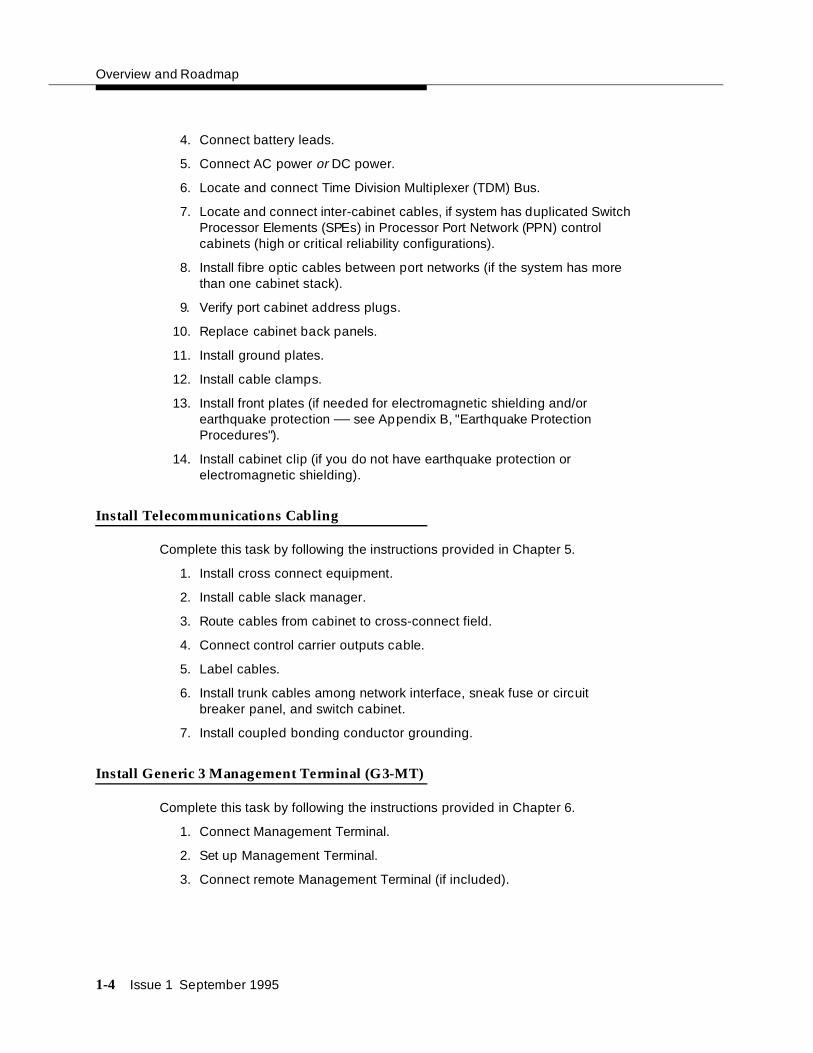
Install Telecommunications Cabling
Complete this task by following the instructions provided in Chapter 5.
1. Install cross connect equipment.
2. Install cable slack manager.
3. Route cables from cabinet to cross-connect field.
4. Connect control carrier outputs cable.
5. Label cables.
6. Install trunk cables among network interface, sneak fuse or circuit breaker panel, and switch cabinet.
7. Install coupled bonding conductor grounding.
Install Generic 3 Management Terminal (G3-MT)
Complete this task by following the instructions provided in Chapter 6.
1. Connect Management Terminal.
2. Set up Management Terminal.
3. Connect remote Management Terminal (if included).

DEFINITY System Installation Roadmap
Issue 1 September 1995 1-5
Activate the System
Complete this task by following the instructions provided in Chapter 7.
1. Power up switch.
2. Log in to the system.
3. Set required country options.
4. Change craft password.
5. Set date and time.
6. Set system maintenance parameters, if Packet Controller (TN778 Circuit Pack) is included.
7. Save and back up translations.
Test the System
Complete this task by following the instructions provided in Chapter 8.
1. Check the system status for each cabinet.
2. Check circuit pack configuration.
3. Test Time Division Multiplexer (TDM) bus in Processor Port Network (PPN).
4. Test Tone-Clock boards.
5. Test Switch Processor Element (SPE) duplication memory shadowing link, only for high and critical reliability systems.
6. Test duplicated Switch Processor Element (SPE) interchange, only for high and critical reliability systems.
7. Test expansion interface boards, if present.
8. Test Time Division Multiplexer (TDM) for each Expansion Port Network (EPN), if Expansion Port Networks (EPN) are present.
9. Test Tone-Clock for each Expansion Port Network (EPN), if Expansion Port Networks (EPN) are present.
10. Test Tone-Clock interchange for each Expansion Port Network (EPN), only for critical reliability systems with Expansion Port Networks (EPN) present.
11. Test expansion interface exchange for each Expansion Port Network (EPN), if Expansion Port Networks (EPNs) are present.
12. Check circuit pack configuration, again.
13. Save and back up translations again, if required.
14. Re-install front doors on switch cabinets.

Overview and Roadmap
1-6 Issue 1 September 1995
Install and Wire Telephones and OtherEquipment
Complete this task by following the instructions provided in Chapter 9.
NOTE:For easier reference, installation steps and test steps are grouped in separate chapters. It may be better to install each hardware component, administer it, and then test it before going on to install another component. As an example, install the Attendant Console using the procedures in Chapter 9, "Install and Wire Telephones and Other Equipment", administer it using the procedures in "Administer the DEFINITY System According to Customer Requirements" on page 1-7, and test it using the procedures in Chapter 10, "Test Telephones and Other Equipment".
1. Make and label wiring cross connections for this customer, using provisioning plan as directed in Step 7 of Chapter 2, "Plan and Prepare the Site".
2. Install and label equipment.
3. Install the attendant consoles.
4. Install the telephones.
5. Install the trunks.
6. Install the interface for the remote management terminal (known as INADS).
7. Install the emergency transfer units and associated telephones.
8. Install external ringing.
9. Install queue warning indicator.
10. Install auxiliary power.
11. Install Basic Rate Interface (BRI) telephone, Basic Rate Interface (BRI) terminating resistor, multipoint adapter, and power adapter.
12. Install auxilliary equipment
13. Install the Processor Data Module (PDM).
14. Install the Call Management System (CMS) interface.
15. Install Property Management System (PMS).
16. Install any customer-provided terminals using Asynchronous Data Units (ADUs).
17. Install Station Message Detail Recording (SMDR)/Call Detail Recording Unit (CDRU) interface.

DEFINITY System Installation Roadmap
Issue 1 September 1995 1-7
Administer the DEFINITY System According toCustomer Requirements
After the hardware is installed and the system is activated, the data for system and telephone features must be administered, using the provisioning plan created for this customer in Step 7 in Chapter 2, "Plan and Prepare the Site". All steps for the administration of the system are provided in the United Kingdom English book, DEFINITY Communications System Generic 3 Implementation, 555-230-655.
Test Telephones and Other Equipment
Complete this task by following the instructions provided in Chapter 10.
1. Make test calls (single-port-network switch).
2. Make test calls (two-port-network switch).
3. Make test calls (three-port-network switch).
4. Test the attendant console and selector console.
5. Test external ringing.
6. Test queue warning indicator.
7. Test integrated announcement.
8. Test music-on-hold.
9. Test emergency transfer.
10. Test remote access interface (known as INADS).
11. Test Basic Rate Interface (BRI).

Issue 1 September 1995 2-1
2Plan and Prepare the Site
This chapter describes tasks required to plan, prepare, and provision the site depending upon which DEFINITY System Generic 3 was ordered. Perform the following:
■ Check the customer’s order.
■ Locate and lay out the equipment room.
■ Lay out and ensure appropriate power.
■ Lay out and ensure appropriate grounding.
■ Determine location of equipment closets.
■ Determine location of external trunk lines.
■ Create a provisioning plan.
Check the Customer’s Order
Determine what was ordered for the customer: DEFINITY System Generic 3, the number of cabinets, port networks, management terminals, adjuncts, consoles, telephones, modems, external trunks, etc.
NOTE:One port network is equivalent to one single-carrier-cabinet stack. Throughout this document, “cabinet” sometimes refers to one single-carrier cabinet and sometimes refers to one stack of single-carrier cabinets, according to the context. An attempt has been made to use “single-carrier cabinet (SCC)” to mean exactly that and to use the more general term, “cabinet,” to mean a stack of one or more single-carrier cabinets or a port network. A “system” is one or more single carrier cabinet stacks.
Plan and Prepare the Site
2-2 Issue 1 September 1995
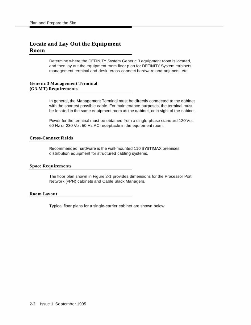
Locate and Lay Out the Equipment Room
Determine where the DEFINITY System Generic 3 equipment room is located, and then lay out the equipment room floor plan for DEFINITY System cabinets, management terminal and desk, cross-connect hardware and adjuncts, etc.
Generic 3 Management Terminal (G3-MT) Requirements
In general, the Management Terminal must be directly connected to the cabinet with the shortest possible cable. For maintenance purposes, the terminal must be located in the same equipment room as the cabinet, or in sight of the cabinet.
Power for the terminal must be obtained from a single-phase standard 120 Volt 60 Hz or 230 Volt 50 Hz AC receptacle in the equipment room.
Cross-Connect Fields
Recommended hardware is the wall-mounted 110 SYSTIMAX premises distribution equipment for structured cabling systems.
Space Requirements
The floor plan shown in Figure 2-1 provides dimensions for the Processor Port Network (PPN) cabinets and Cable Slack Managers.
Room Layout
Typical floor plans for a single-carrier cabinet are shown below:

Locate and Lay Out the Equipment Room
Issue 1 September 1995 2-3
Additional Notes:
AC receptacles must be separately current protected (fuse or circuit breaker) and not under the control of a wall switch. Receptacles must not be shared with other equipment and should be located away from the cross-connect field.
System must be grounded by one of the approved methods. See Appendix A.
Earthquake protection and/or electromagnetic shielding may be required. See Appendix B.
Figure 2-1. Typical Floor Plan for G3i Single-Carrier ProcessorPort Network (PPN) with Expansion Port Network(EPN) Cabinets
3
84
9
5
10
1
6
7
2
14
13
1212
11
1. Printer (Optional)
2. Wall
3. Table
4. Trunk/Auxiliary Field. May be Located within Cross-Connect Field.
5. G3 Management Terminal (G3-MT)
6. Processor Port Network (PPN) Cabinets
7. Cable Slack Manager
8. Cross-Connect Field
9. Cable Slack Manager (Optional)
10. Expansion Port Network (EPN) Cabinets (optional). Space indicated by callouts 9 and 10 needed for each Expansion Port Network (EPN) in system.
11. 22 Inches (55 cm)
12. 27 Inches (68 cm)
13. 32 Inches (81 cm)
14. 40 Inches (101 cm)
Figure Notes:

Plan and Prepare the Site
2-4 Issue 1 September 1995
Cable Slack Manager (Optional) Requirements
A cable slack manager (optional) is 32 inches (81 cm) wide and 40 inches (102 cm) deep. Normally, one slack manager is needed for each cabinet stack. Extra slack managers may be ordered, if necessary.
Tools Needed
Table 2-1 lists the tools and test equipment required to install the switch. Make sure all tools are available before installing the DEFINITY System Generic 3.

Locate and Lay Out the Equipment Room
Issue 1 September 1995 2-5
* Electric drill and drill bits are required for earthquake mounting.
† Since U.S./English fasteners are used, U.S./English tools are required unless an exact match canbe found among metric tools.
‡ Required when installing an AC powered switch.
Table 2-1. Tools and Test Equipment Inventory
Tasks Equipment RequiredRecommended Type
Recommended Types for Europe
UnpackingCabinet
Tin Snips
Utility Knife
Adjustable Wrench 6- or 8-inch
InstallingCabinet*
Electric Drill Impact type
Masonry Bit 1/2-inch
Drill Bit (for Computer Floors only)
5/8-inch
Drift Punch Length as required to reach from computer floor to concrete floor
Chalk Line
Rule 30-inch
Adjustable Wrench 6- or 8-inch
Ratchet 1/2-inch 1/2-inch †
Sockets 5/16-, 1/2-, and 3/4-inch
5/16-, 1/2-, and 3/4-inch †
Nut driver 1/4-inch 1/4-inch †
Screwdriver 8-inch flat blade
Allen Wrench ‡ 1/8-inch
Checking Commercial Power
Digital Multimeter KS-20599
Circuit Pack Voltage Check
Voltage Tester TN2036 (optional)
Initializing Switch Generic 3 Management Terminal 715 Management Terminal
Installing cables and telephones
Diagonal cutters
Phillips screwdriver
Electric drill for installing information outlets
Impact tool for cross-connect hardware
Test (telephone) set

Plan and Prepare the Site
2-6 Issue 1 September 1995
Lay Out and Ensure Appropriate Power
1. Lay out and ensure appropriate power for switch cabinets and management terminal in equipment room.
2. Provide one power outlet per single-carrier cabinet.
3. Have an electrician check the commercial power and verify power is available and present.
Power Arrangements for AC Power
The following procedures apply to both the Processor Port Network (PPN) cabinet(s) and Expansion Port Networks (EPN) cabinet(s) (as provided), except where noted.
The following illustration shows a typical power and grounding layout, and the illustration after that shows the AC power receptacle requirements. The power circuit must be dedicated to the DEFINITY System Generic 3 only and must be on a separately current limited (fuse or circuit breaker) circuit. It must not be shared with other equipment and must not be under the control of a wall switch. The power supply for the Generic 3 Management Terminal (G3-MT), however, does not have to be dedicated
Locate and/or arrange the cross-connect field so all power receptacles are accessible.

Locate and Lay Out the Equipment Room
Issue 1 September 1995 2-7
Power Arrangements for DC Power
The following table shows the input DC requirements for the system -48 VDC Input Power Requirements
Parameter Requirements
Static Voltage -48 VDC nominal, -42.5 VDC minimum, -52.5 VDC maximum (measured at input to System cabinet) under normal operating conditions.
Dynamic Voltage
Transient change in voltage— +/- 5% of steady state voltage. Allowed transient duration—Up to 200 milliseconds.
AC Ripple Voltage
Maximum wideband AC ripple— 450 mvpp (millivolts peak-to-peak) in the 3 kHZ to 20 MHZ band.
Low Voltage Disconnect
Automatic disconnect—Occurs when input voltage is less than -42.5 VDC (control provided with battery plant).
Overvoltage Protection
Input voltage at switching cabinets shall not exceed -52.5 VDC.
Voltage Drop Maximum drop—Must not exceed 0.5 VDC one way on feeder cables between the power board and the System cabinet. Feeders must be Underwriter Laboratories (UL) approved (or equivalent) and Canadian Safety Association (CSA) certified. Recommended -48 VDC feeder cable—Royal Electric #X4905 or equivalent No. 1 AWG is required for distances up to 50 feet (15 meters). Cable resistance must be equal to or less than 0.1290 ohms per 1000 feet 304 meters).
Current Draw The battery plant rectifiers must be capable of providing current for the System including that required for System holdover and for charging the batteries. In addition, this may include DC current required for an inverter that provides Occupier to peripheral equipment if it is installed and for future growth.
Circuit Breaker An Underwriter Laboratories (UL) listed and Canadian Safety Association (CSA) certified circuit breaker must be provided at the battery plant power board for each System cabinet feeder. The recommended circuit breakers are 75 ampere Airpax UPL-1-1REC2-52-753 or Heinemann AM1-B2-A-75-2.
Redundancy Redundancy of the battery chargers/rectifiers should be considered. This would also provide the additional current necessary to recharge the batteries after being fully discharged.

Plan and Prepare the Site
2-8 Issue 1 September 1995
Lay Out and Ensure Appropriate Grounding
Grounding is relatively simple for an AC-powered switch. First, connect the cabinets to each other. Then, connect a single ground wire from the Processor Port Network (PPN) to the approved protective ground.
Grounding of the system must comply with the general rules for grounding contained in Article 250 of the National Electrical Code (NEC), National Fire Protection Agency (NFPA) 70, or the applicable electric code in your country. See Appendix A for a description of “approved ground.”
Connect Coupled Bonding Conductor
The Coupled Bonding Conductor connects to the single-point-ground-block and runs adjacent to pairs in an associated telecommunications cable. The mutual coupling between the bonding conductor and the pairs reduces potential differences in terminating equipment. The conductor consists of a 10 AWG wire that must be tie-wrapped to the inside wiring cable and terminated at the coupled bonding conductor terminal bar at the switch cross-connect field.
Refer to Appendix F for wire conversion information.
Refer to Figure 4-9 on page 4-13 for an illustration of a Coupled Bonding Conductor.
If the approved protective ground or approved floor ground can only be accessed inside a dedicated power equipment room, you should have an electrician make the connections to this ground.
Electrical Noise
Voice band noise from the battery plant to the system must be less than 32 dBrnC (decibels above reference noise with C-filter or -58 dBmp (decibels below 1 milliwatt psophometric).
Grounding A single point ground must be maintained. A ground conductor must be installed from the battery plant GROUND DISCHARGE BAR to the closest “Approved Ground” via the shortest and most direct route as required by the National Electrical Code or applicable electrical code in your area. The gauge must be no smaller than the largest conductor in the System and larger than 6 AWG. Grounding between the system cabinet and the battery plant should be connected using the procedures given later in this chapter.
Lightning Protection
There must be adequate lightning protection in the battery plant to insure that the system will not be damaged.
Parameter Requirements

Determine the Location of the Equipment Closets
Issue 1 September 1995 2-9
NOTE:Check location of the AC power receptacle. The receptacle must be on a separately current limited (fuse or circuit breaker) circuit not controlled by a wall switch.
Determine the Location of the Equipment Closets
Determine the location of the equipment closets where large cables can be connected out into smaller ones. Determine locations of terminating resisters for Basic Rate Interface (BRI) station circuits to be installed in equipment closets.
Determine External Trunk Locations
Determine where external trunk lines come into the building and be routed to the equipment room. Determine where external trunk converters and adapters as well as sneak-current fuse panels will be installed in the switch room (preferably close or next to the cross connect fields).
Create a Provisioning Plan
Determine an appropriate available port circuit on the DEFINITY System for each telephone, trunk, and peripheral connection needed, and, in addition, plan for auxiliary power for Basic Rate Interface (BRI) and certain display sets.
Create a provisioning plan to include the following (see the example on the following page):
■ Station or trunk type or feature/service.
■ Building location (floor/room/desk/information outlet).
■ Extension number or trunk group and member number.
■ Port circuit location on the switch for each endpoint (DEFINITY System Generic 3 cabinet/carrier/slot/circuit.
■ Route from switch room through equipment closets to each endpoint.
■ Auxiliary power supply, if required.

Plan and Prepare the Site
2-10 Issue 1 September 1995
.
Table 2-2. Example of a Provisioning Plan
Station or Trunk Type or Feature/Service
Building Location (floor/room/desk/information outlet
Extension Number or Trunk Group and Member
DEFINITY G3 cabinet/carrier/slot/circuit
Route from equipment closets
Auxiliary Power Required?
8410
8403
Attendant Console
Analog CO
Digital Tie
.....
Music on Hold

September 1995 Issue 1 3-1
3Unpack the Cabinet
This chapter describes the system unpacking procedures.
The DEFINITY System Generic 3 (G3) single-carrier cabinets are shipped in a polyethylene bag, packed in a cardboard container. The cabinet is fastened to a wood/Styrofoam pallet with two metal bands. The cardboard container is strapped to the pallet with another metal band.
! DANGER:Lifting the cabinet requires two people, as it may weigh as much as 130 pounds/60 kilograms. Use caution to avoid injury.
Unpack and Inspect for Damage
Unpacking the Cabinets
To unpack the cabinets, complete the following steps:
1. Check the status of the SHOCKWATCH and/or TILTWATCH indicators on the cardboard container. These indicators are white under normal conditions. If the container has been shaken or tilted beyond specifications, the indicators will be red, indicating potential damage. Report any damage according to local shipping instructions.
2. Remove the cabinet from the cardboard container.
! DANGER:Take care to avoid injury while cutting and removing bands.
3. Remove all cardboard, tape, and plastic.

Unpack the Cabinet
3-2 September 1995 Issue 1
! CAUTION:Deep knife penetration may damage the cabinet.
4. Open and remove the front door and back panels from cabinet. The screw location is shown in the following figures.
Figure Notes:
1. Screw that opens front cabinet door
Figure 3-1. Front Cabinet Door Latch Screw Location
Figure 3-2 shows the back panel screw locations.
1

September 1995 Issue 1 3-3
Figure Notes:
1. Screws to remove
2. Screws to loosen
3. Screws to remain
Figure 3-2. Back Cabinet Panel Screw Locations
1. Remove all packing material from inside the cabinet.
Inspect Cabinet
2. Inspect cabinet for any damage that may have occurred during shipping. Report any damages according to local shipping instructions.
3
2
1 1
2 2
3
2
1 1

Unpack the Cabinet
3-4 September 1995 Issue 1
3. Verify the label near the circuit breaker on the power supply toward the rear of each cabinet corresponds to your local voltage type.
! DANGER:If the label is different than the voltage type at your site, notify your A T & T representative immediately for a replacement power supply. Do not , under any circumstances, connect the system to power!
Check Circuit Packs
4. Ensure all circuit packs are fully inserted into the proper slots according to the Customer Service Document (CSD). Report any discrepancies in circuit pack type or quantity to your AT&T representative.

Issue 1 September 1995 4-1
4Install and Connect the Cabinets
This chapter describes how to install the Processor Port Network (PPN) and Expansion Port Network (EPN) single-carrier cabinets for DEFINITY System Generic 3. Directions are provided for the following configurations:
■ Standard reliability
■ High reliability
■ Critical reliability
Refer to About This Book for a description of each configuration.
This chapter discusses single-carrier cabinets only. For information on multiple-carrier cabinets, refer to the DEFINITY Communications System Generic 1 and Generic 3 Installation and Test document.
To install the cabinets, complete the following steps as detailed in this chapter:
1. Install earthquake floor mounting (if earthquake protection is required)
2. Position and stack cabinets
3. Connect grounds and Connect AC power or DC power
4. Connect Time Division Multiplexing (TDM) cables
5. Connect inter-cabinet cables (ICC)
6. Verify address plug settings
7. Install back plates
8. Install ground plates
9. Install front cabinet clips or ground plates
10. Connect fibre-optic cables
11. Install doors

Install and Connect the Cabinets
4-2 Issue 1 September 1995
Install Earthquake Mounting
If earthquake protection is required for your area, install earthquake floor mounting as directed in Appendix B.
Position and Stack the Cabinets
Follow the diagram in the Customer Service Document (CSD) shipped with each cabinet, and stack the DEFINITY System Generic 3 cabinets using these steps:
1. Place the control cabinet in position at the location determined when room layout was planned.
NOTE:Check location of the AC/DC power receptacle. The receptacle must be on a separately fused circuit not controlled by a wall switch. It must be located within 10 feet (3 meters) of the cabinet, and should be located outside the cross-connect field area.
2. Stack the single-carrier cabinets by letter, according to the serial numbers and lettered designation strips in the Customer Service Document (CSD), and as shown in Figure 4-1.
Figure 4-1. Cabinets Stacked by Letter
3. Remove the front cabinet door and back cabinet panel. See "Unpack and Inspect for Damage" on page 3-1 for more information.
D
B
C
A

Connect System Cabinet Grounds
Issue 1 September 1995 4-3
Connect System Cabinet Grounds
To connect ground, refer to Figure 4-2 on page 4-4 and perform the following:
1. At lower left rear of the Processor Port Network (PPN) cabinet (Control Cabinet A), connect a 6 AWG ground wire to the cabinet ground block. See Appendix F for international wire conversions for outside North America.
NOTE:A screwdriver is required to loosen and tighten the screws securing the ground wire to the ground block.
2. Run the ground wire to an approved ground. Refer to Appendix A.
3. At the Expansion Port Network (EPN) cabinet(s) (as provided), connect a 6 AWG ground wire to the A-cabinet ground block.
4. Run the ground wire from the Expansion Port Network (EPN) to the Processor Port Network (PPN) cabinet and connect it to the cabinet ground block.
NOTE:If the Expansion Port Network (EPN) cabinet is remotely located from the Processor Port Network (PPN) cabinet (in a separate room or building), run the 6 AWG cabinet ground wire to an approved protective ground.
5. At the Processor Port Network (PPN) cabinet, connect a 10-AWG wire to the cabinet ground block. At a later time, tie-wrap the ground wire (coupled bonding conductor) to the trunk cables, terminating it at the coupled bonding conductor terminal bar at the cross-connect field for the switch. Refer to Figure 4-9 on page 4-13 for an illustration of the coupled bonding conductor.

Install and Connect the Cabinets
4-4 Issue 1 September 1995
Figure 4-2. Typical AC Power and Grounding Arrangementfor Single-Carrier Cabinet (Rear View)
ON ON
OFF OFF
ON ON
OFF OFF
ON ON
OFF OFF
ON ON
OFF OFF
8
13
9
5
10
6
11
7
7 7712
12
1 1
3
4
2
1. Expansion Port Network (EPN) Control Cabinet A
2. Circuit breaker
3. Power supply
4. Power receptacle in power supply
5. Processor Port Network (PPN) Control Cabinet A
6. Cabinet-stack single-point ground block
7. Power cord 2.5 meters
8. National Electrical Manufacturer’s Association (NEMA) 5-15 or National Electrical Manufacturer’s Association (NEMA)5-20 receptacle or equivalent locally provided receptacles
9. 6 AWG ground wire to approved ground
10. Generic 3 Management Terminal (G3-MT)
11. 10 AWG Coupled Bonding Conductor
12. 6 AWG cabinet-stack ground conductor
13. Port cabinet
Figure Notes:

Connect Battery Leads
Issue 1 September 1995 4-5
Connect Battery Leads
To prevent the batteries from discharging, the control cabinet is shipped with the battery lead disconnected. To connect the batteries, perform the following:
At cabinet(s):
1. Ensure the circuit breakers on each cabinet are OFF.
Each cabinet has its own power supply and the circuit breaker is located on the rear of each power supply. See Figure 4-3.
2. Connect the battery lead:
See Figure 4-3. The battery is near the top of the carrier toward the front-right. The battery leads should be immediately next to the battery, on the left side, and accessible from the front of the cabinet.
Figure Notes:
1. Battery
2. Circuit Breaker
3. Ground block
Figure 4-3. Single Carrier Cabinet Control CabinetBattery Location, Right Side View
1
2
3

Install and Connect the Cabinets
4-6 Issue 1 September 1995
Connect Power
Connect either AC or DC power as described in this section.
Verify the label near the circuit breaker on the power supply toward the rear of each cabinet corresponds to your local voltage type.
! DANGER:If the label is different than the voltage type at your site, notify your A T & T representative immediately for a replacement power supply. Do not , under any circumstances, connect to power!
Connect AC Power
Figure 4-2 applies to multiple Processor Port Networks (PPN) and Expansion Port Network (EPN) cabinet arrangements. If multiple Expansion Port Network (EPN) cabinets are required, you must provide the receptacles for the 4-cabinet Processor Port Network (PPN) arrangement in addition to the receptacles for a 2-, 3-, or 4-cabinet Expansion Port Network (EPN) arrangement. Provide one receptacle per single-carrier cabinet.
1. Verify the circuit breakers are OFF .
2. Connect cabinet AC line cords to the AC power receptacles. The AC line cords for the cabinets must first be connected to the cabinets and then to the AC power receptacles.
Connect DC Power
The following procedures apply to both the Processor Port Networks (PPN) and Expansion Port Networks (EPN).
Figure 4-4 shows a typical power and grounding layout for a DC-powered single-carrier cabinet. The size of the wire required for the -48 VDC and -48 volt return must ensure the -48 VDC supplied by the battery plant to the cabinets will be maintained between -42.5 and -52.5 volt DC. This ensures proper operation and prevents hardware damage.

Connect Power
Issue 1 September 1995 4-7
GRD
-48V
-48V RTN1
GRD
-48V
-48V RTN1
GRD
-48V
-48V RTN1
GRD
-48V
-48V RTN1
-48VRTN
-48V
GRD
1
1
1
1
1
1
1
1
3
8
13
18
4
9
14
5
5
10
15
15
15
15
1
1
1
6
11
11
16
16
16
2
2
2
2
7
7
7
12
17
(-48V RTN & GRD)
75A-48V
-48V
GRD
GRD
-48V
-48V RTN75A

Install and Connect the Cabinets
4-8 Issue 1 September 1995
Figure 4-4. Typical Single-Carrier Cabinet System DirectCurrent (DC) Power and Grounding Wiring
! CAUTION:Grounding of the system shall comply with the general rules for grounding contained in Article 250 of the National Electrical Code (NEC), National Fire Protection Agency (NFPA) 70, or the applicable code in your area. See Appendix G for more information.
Determine the approved ground in the building to be wired. See Appendix A. Connect your system to an approved ground as described below.
1. Ground plate (three required)
2. 3 Conductor No.10 line cord (one per cabinet)
3. Plug (male)
4. J58890CG DC Distribution Unit
5. Receptacle (female)
6. Cabinet single-point ground block
7. 6 AWG wire
8. 25 Amp Fuse (4 required)
9. Coupled bonding conductor to terminal bar at cross-connect field
10. Ground discharge bar
11. 1 AWG wire
12. Approved ground
13. To cabinet single-point ground block in next port cabinet
14. To DC distribution unit for next port network
15. 676B DC Power Supply
16. Port Cabinet
17. Control Cabinet
18. Battery Plant
Figure Notes:

Connect Power
Issue 1 September 1995 4-9
Connect Power Plant Ground
To connect the power plant ground, complete the following steps:
1. At the DC power cabinet, connect a 1 AWG ground wire to the GROUND DISCHARGE bar.
2. Route the ground wire out of the cabinet and terminate it on the approved ground (see Figure 4-5). The approved ground must be identified with a grounding tag (AT&T FORM 15657NR, or equivalent).
Figure 4-5. Power Plant Grounding
1
2
3
4
1. 1 AWG wire
2. Approved ground. Must be connected to an approved ground using the correct gauge cable, terminated with a listed clamp, and identified with an AT&T ground tag or equivalent.
3. DC Power Cabinet
4. Ground discharge bar
Figure Notes:

Install and Connect the Cabinets
4-10 Issue 1 September 1995
Connect Frame Ground
Connect the 6 AWG frame ground cable to the cabinet frame by following these steps:
1. Measure and cut a length of 6 AWG cable. Use the provided cable or measure and cut a length of 6 AWG cable long enough to reach between the GROUND CONNECTION terminal in the DC Battery Cabinet and the GROUND DISCHARGE bar in the DC Power Cabinet.
2. Crimp terminal lugs on each end of the wire. Terminal lugs are furnished as part of D-181895, Kit of Parts.
3. At DC power cabinet, connect wire to the GROUND DISCHARGE bar.
4. Route the wire through one of the holes in the side of the cabinet and terminate it on the GROUND CONNECTION terminal in the DC Battery Cabinet (see Figure 4-6).
Figure 4-6. Frame Ground Grounding
1
3
4
5
2
1. 6 AWG wire
2. Ground discharge bar
3. DC battery cabinet
4. Ground connection terminal
5. Power distribution unit
Figure Notes:

Connect Power
Issue 1 September 1995 4-11
Connect DC Power Distribution Box Grounding
Run the 6 AWG ground cable from the DC Power Cabinet to each DC Power Distribution Unit, using the following steps:
1. At the DC Power Cabinet, connect 6 AWG wire to the GROUND DISCHARGE bar. Route the cable to the DC Power Distribution Unit. Connect the cable to the GRD Terminal Block in the DC Power Distribution Unit (see Figure 4-6).
2. Repeat Step 1 for each remaining DC Power Distribution Unit.
Figure 4-7. DC Power Distribution Unit Grounding (J58890CG)
Connect Single-Carrier Network Grounding
Each port cabinet must have a 6 AWG ground cable connected from the ground block of Control Cabinet A to the DC Power Cabinet.
Use the following instructions to connect each network ground:
1
2
3
4
5
6
1. 6 AWG wire
2. To additional J58890CG as provided
3. DC power cabinet
4. Ground discharge bar
5. Power distribution unit
6. Ground terminal strip
Figure Notes:

Install and Connect the Cabinets
4-12 Issue 1 September 1995
1. At the DC Power Cabinet, connect a 6 AWG cable to the GROUND DISCHARGE bar. Route the cable to the port Cabinet Carrier A. Connect the cable to the single-point ground block in the Control Carrier (see Figure 4-7).
2. Repeat Step 1 for each port Cabinet Carrier A in the system.
Figure 4-8. Ground Connection for Single-Carrier Network
Coupled Bonding Conductor (CBC)
The coupled bonding conductor (CBC) connects the cabinet single-point ground block to the approved protective ground located nearest the (telephone company owned) protector block at the building entrance facility. Follow these steps to connect the coupled bonding conductor:
1
2
3
4
5
6
7
8
9
10
1. 6 AWG wire
2. Ground plate
3. Cabinet stack single point ground block
4. To additional Port Cabinet as provided
5. DC Power Cabinet
6. Ground discharge bar
7. Port Cabinet D
8. Port Cabinet C
9. Port Cabinet B
10. Port Cabinet A
Figure Notes:
Connect Power
Issue 1 September 1995 4-13
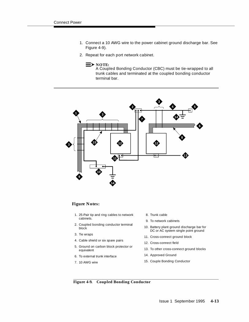
1. Connect a 10 AWG wire to the power cabinet ground discharge bar. See Figure 4-9).
2. Repeat for each port network cabinet.
NOTE:A Coupled Bonding Conductor (CBC) must be tie-wrapped to all trunk cables and terminated at the coupled bonding conductor terminal bar.
Figure 4-9. Coupled Bonding Conductor
3
3
3
8
13
4
9
14
14
5
10
15
1
6
11
2
7
12 12
1. 25-Pair tip and ring cables to network cabinets.
2. Coupled bonding conductor terminal block
3. Tie wraps
4. Cable shield or six spare pairs
5. Ground on carbon block protector or equivalent
6. To external trunk interface
7. 10 AWG wire
8. Trunk cable
9. To network cabinets
10. Battery plant ground discharge bar for DC or AC system single point ground
11. Cross-connect ground block
12. Cross-connect field
13. To other cross-connect ground blocks
14. Approved Ground
15. Couple Bonding Conductor
Figure Notes:
Install and Connect the Cabinets
4-14 Issue 1 September 1995
! CAUTION:System grounding shall comply with the general rules for grounding contained in Article 250 of the National Electrical Code (NEC), National Fire Protection Agency (NFPA) 70, or your applicable local electrical code. See Appendix A for a description of “approved ground.”
Connect DC Power to Networks
Each port cabinet stack must have a DC Power Distribution Unit associated with it. Each DC Power Distribution Unit furnishes DC power for four single-carrier cabinets. The DC Power Distribution Unit comes equipped with four power cords. Each 10 foot (3 meter) cord is equipped with the appropriate connectors.
Perform the following to connect each network to the DC Power Distribution Unit:
1. Connect 1 AWG wire for -48V and -48V return from DC Battery Plant to each DC Power Distribution Unit.
2. At the J58890CG DC Power Distribution Unit, connect the power cable to an available receptacle. Route the cable to the rear of Cabinet A. Connect the power cord to the DC connector on the rear of Cabinet A.
3. Repeat Step 1 for Cabinets B, C, and D as required.
4. Repeat Steps 1 and 2 for all remaining port cabinets.
Connect AC Power to DC Power Cabinet
Connect the AC power to the DC Power Cabinet by performing the following:
1. Ensure the associated circuit breakers at the AC power panel OFF.
2. Have an electrician connect AC power leads to the rectifiers using the instructions provided with the rectifiers in the DC Power Cabinet. Each rectifier should have its own branch circuit. Terminate leads on the AC INPUT terminal block of each rectifier.
Test DC Power Plant
To test the DC power plant, refer to the Installation Test Procedure (ITP) in the LINEAGE 2000 ECS Power System Battery Plant Product Manual, 167-790-020.
Connect Stand-by Power
An external, commercial Uninterruptible Power Supply (UPS) or a battery backup arrangement may be provided. Stand-by power is engineered to customer needs depending on the size and configuration of the system.
The AT&T GBCS Power System is recommended; use the installation instructions provided. See your AT&T representative for more information.
Locate and Connect Time Division Multiplexing (TDM) Bus
Issue 1 September 1995 4-15
Locate and Connect Time Division Multiplexing (TDM) Bus
Locate the white fabric-covered Time Division Multiplexing (TDM) bus cable. Refer to Table 4-1 for slot information.
Follow these instructions to connect the bus to the appropriate slots.
1. Remove the Time Division Multiplexing (TDM) bus terminator on Slot 22 of Control Cabinet A and move it to the Time Division Multiplexing (TDM)/Local Area Network (LAN) pinfield at the equipment location (EQL) on the top port cabinet. See Figure 4-10.
2. Connect the bus cables as shown in Figure 4-10. The cable is located behind the lower panel when the cabinet is shipped.
Table 4-1. Time Division Multiplexing (TDM) Bus Connections
Configuration Cabinet/Slot
Backplane Time Division Multiplexing (TDM)/Local
Area Network (LAN) Pinfield at EQL
Cabinet/Slot
Processor Port Network (PPN), High or Critical Reliability
A/22 B/02
B/22 C/00
C/17 D/00
Expansion Port Network (EPN), Standard, High or Critical Reliability
A/18 B/00
B/17 C/00
C/17 D/00
Processor Port Network (PPN), Standard Reliability
A/22 B/00
B/17 C/00
C/17 D/00

Install and Connect the Cabinets
4-16 Issue 1 September 1995
Figure 4-10. Time Division Multiplexing (TDM) BusConnections for Standard-Reliability ProcessorPort Network (PPN)
AAAAAAAAAAAAAAAAAAAAAAAA
AAAAAAAAAAAAAAAAAAAAAAAA
AAAAAAAAAAAAAAAAAAAAAAAA
AAAAAAAAAAAAAAAAAAAAAAAA
AAAAAAAAAAAAAAAAAAAAAAAA
AAAAAAAAAAAAAAAAAAAAAAAA
AAAAAA
AAAAAAAAAAAAAAAAAAAAAAAAAAAA
AAAAAAAAAAAAAAAAAAAAAAAAAAAA
AAAAAAAAAAAAAAAAAAAAAAAAAAAA
AAAAAAAAAAAAAAAAAAAAAAAAAAAA
AAAAAAAAAAAAAAAAAAAAAAAAAAAA
AAAAAAAAAAAAAAAAAAAAAAAAAAAA
AAAAAAA
3
3
2
4
1
5
AAAAAAAAAAAAAAAAAAAAAAAA
AAAAAAAAAAAAAAAAAAAAAAAA
AAAAAAAAAAAAAAAAAAAAAAAA
AAAAAAAAAAAAAAAAAAAAAAAA
AAAAAAAAAAAAAAAAAAAAAAAA
AAAAAAAAAAAAAAAAAAAAAAAA
AAAAAA
AAAAAAAAAAAAAAAAAAAAAAAA
AAAAAAAAAAAAAAAAAAAAAAAA
AAAAAAAAAAAAAAAAAAAAAAAA
AAAAAAAAAAAAAAAAAAAAAAAA
AAAAAAAAAAAAAAAAAAAAAAAA
AAAAAAAAAAAAAAAAAAAAAAAA
AAAAAA
1
3
2
4
2
4
1. Time Division Multiplexing (TDM) bus terminator AHF110 on Time Division Multiplexing)/Local Area Network pinfield (TDM/LAN)
2. Time Division Multiplexing/Local Area Network pinfield (TDM/LAN) at equipment location (EQL) (see Table 4-1 on page 4-15)
3. Time Division Multiplexing (TDM) bus cable WP91716 L3
4. Port cabinet (standard reliability), or duplicate control cabinet (high or critical reliability)
5. Control cabinet
Figure Notes:

Locate and Connect Inter-Cabinet Cables (ICC)
Issue 1 September 1995 4-17
Locate and Connect Inter-Cabinet Cables (ICC)
Connect the Inter-Cabinet Cables (ICC) using these steps:
1. Remove the Inter-Cabinet Cable (ICC) from the lower back shelf of the cabinet.
2. Connect the cables as shown in Figure 4-11 and Table 4-2.
Table 4-2. Inter-Cabinet Cable Connections
From Cabinet A To Cabinet BCabinet Carrier Connection Carrier Connection
Processor Port Network (PPN)
J58890L (ICC) A J58890M (ICC) A
(ICC) B (ICC) B
(ICC) C (ICC) C
Expansion Port Network (EPN)
J58890N (ICC) A J58890H (ICC) A
(ICC) B (ICC) B

Install and Connect the Cabinets
4-18 Issue 1 September 1995
Figure 4-11. Inter-Cabinet Cable (ICC) Connections forStandard Reliability Expansion Port Network(EPN) Cabinet Stack
AAAAAAAAAAAAAAAAAAAAAAAAAAAAAAAA
AAAAAAAAAAAAAAAAAAAAAAAAAAAAAAAA
AAAAAAAAAAAAAAAAAAAAAAAAAAAAAAAA
AAAAAAAAAAAAAAAAAAAAAAAAAAAAAAAA
AAAAAAAAAAAAAAAAAAAAAAAAAAAAAAAA
AAAAAAAAAAAAAAAAAAAAAAAAAAAAAAAA
AAAAAAAAAAAAAAAAAAAAAAAA
AAAAAAAAAAAAAAAAAAAAAAAAAAAAAAAA
AAAAAAAAAAAAAAAAAAAAAAAAAAAAAAAA
AAAAAAAAAAAAAAAAAAAAAAAAAAAAAAAA
AAAAAAAAAAAAAAAAAAAAAAAAAAAAAAAA
AAAAAAAAAAAAAAAAAAAAAAAAAAAAAAAA
AAAAAAAAAAAAAAAAAAAAAAAAAAAAAAAA
AAAAAAAAAAAAAAAAAAAAAAAA
1
2
345
1. Pinfield per Table 4-2
2. Cabinet in Position B
3. Inter-Cabinet Cables
4. Backplane
5. Control Cabinet A Position
■ Rear of Cabinets Shown
Figure Notes:

Install Fibre-Optic Cables
Issue 1 September 1995 4-19
Install Fibre-Optic Cables
This section discusses the hardware and methods required to connect and route fibre-optic cables.
The Expansion Port Network (EPN) cabinet is normally positioned next to the Processor Port Network (PPN) cabinet(s), but may also be installed in a different room or a different building. Fibre-optic cables connect the cabinets together.
Fibre-Optic Cable Operation
Fibre-optic cables carry signals between the cabinets that compose your switch. To do this, the electronic signals at the connectors on the back of a cabinet are converted into optical signals. The optical signals from another cabinet are then converted back into electronic signals. AT&T provides opto-electronic devices, the 9823-type lightwave transceivers, that perform this task.
A completed signal from one cabinet goes through a transceiver, a fibre-optic cable, and another transceiver to reach another cabinet. If the two cabinets are close together, the optical signal may go through a single, directly connected fibre-optic cable. If the two cabinets are far apart, it may be convenient to connect the cabinets through the cross-connect field.
Figure 4-13 shows how to connect fibre-optic cables for direct connections.
Figure 4-14 shows how to connect fibre-optic cables through a cross-connect field. .
Locate Fibre-Optic Cable Connections
Packed with the system is a Customer Service Document (CSD) that includes an “Inter-Cabinet Cable Running List.” Each row on the list represents a fibre-optic cable connection.
The list includes the AT&T comcode of the cable to be used, its length (in feet) and the addresses of each cable’s source and destination. These addresses include the numbers of the cabinets, carrier positions, and slots to which you are to connect the cables. Use the information from the Running List to determine where to connect each fibre-optic cable.
Figure 4-12 illustrates an example Running List.

Install and Connect the Cabinets
4-20 Issue 1 September 1995
Figure 4-12. Typical Fibre-Optic Cable Running List
In the example Running List in Figure 4-12, connect a cable labeled 104266465 (20 feet long) from Cabinet 1, Carrier C, Slot 2, to Cabinet 2, Carrier B, Slot 2.
NOTE:The following tasks refer to the Running List and offer typical installation instructions. If any conflict between specific details in the Running List and the instructions given in the following procedures arise, cable your system according to the Running List provided with your system.
General Rules and Recommendations forConnecting Fibre-Optic Cables
Although fibre-optic cables withstand some misuse, it does require careful handling and routing.
Follow these rules and recommendations when installing fibre-optic cables:
Rule 1
Cross-connect the fibre-optic cable between two 9823-type lightwave transceivers. That is, run the cable from the connector marked TX on one transceiver to the connector marked RX on the other transceiver, and in reverse for the other cable.
Do this for each connection (row) on the Running List contained in the Customer Service Document (CSD) shipped with your system. See Figure 4-12 for a sample Running List.
Rule 2
Use the 9823A (shortwave) transceiver for distances of up to 4900 feet. Use the 9823B (longwave) transceiver for distances of up to 25,000 feet. Ensure all 9823As are connected to 9823As and all 9823Bs are connected to the corresponding 9823Bs.
Connection From
SD67975-01Cable Code Length From To
Cabinet Position Slot Cabinet Position Slot
CAD3 104266465 20 ft. 01 C 02 02 B 02
CAD3 104266465 20 ft. 01 D 02 02 A 01

Install Fibre-Optic Cables
Issue 1 September 1995 4-21
Rule 3
Route fibre-optic cables away from groups of other cables where they may be stretched by the weight of metal cable bundles, as fibre-optic cables are quite flexible.
Rule 4
Avoid bending fibre-optic cables to a radius smaller than 1-1/2 inches (4 cm), to prevent mechanical stress on the cables, as they are rather delicate. Plan your use of cable ties to avoid crimping the cable or creating a fixed stress point where, at a later time, movement of the cable causes it to exceed the minimum bend radius.
Rule 5
Ensure fibre-optic cables are not pressed against any sheet metal edges by subsequently installed cables.
Recommendation
In some such systems it may be required to run fibre-optic cables with the input/output cables, such as in the cable slack manager or under a raised floor. In these situations, protect the cable by running it in a dedicated area if possible. When you must run the cable with other cabling, protect it by running it through flexible conduit.
In the following illustration, the slot locations are for example purposes only.

Install and Connect the Cabinets
4-22 Issue 1 September 1995
Figure 4-13. Fibre-Optic Cable Installation Between Shortwave Transceivers, Direct Connection
TX
RX
1
2
2
1
TX
RX
12
3
4
1. Processor Port Network (PPN) Cabinet A Slot 2A01 / 9823-Type lightwave transceiver
2. FL2P-P-20 Fiber optic cable
3. Expansion Port Network(EPN) Cabinet A Slot 1A01 / 9823-Type lightwave transceiver
4. Fiber optic cable sheath, containing two fibers, each labeled 1 and 2, respectively
Figure Notes:

Install Fibre-Optic Cables
Issue 1 September 1995 4-23
Figure 4-14. Fibre-Optic Cable Installation BetweenLongwave Transceivers Through Fibre-OpticCross-Connect Field
Raised Floor or Cable Slack Managers
Figure 4-15 shows the recommended fibre-optic cable routing for a single-carrier cabinet system with a cable slack manager or on a raised floor.
In these situations, use the following steps to route the cable:
1. Route the fibre-optic cable up toward the top of the cabinet. The excess cable should be looped and draped from the B25A cable clamp on the top ground plate in the stack.
2. Dress the cable running up the back of the cabinets by tie wrapping the cable to the outside of the B25A cable clamp (do not put the cable inside the clamp holding the B25A cables).
TX
RX
1
2
2
1
TX
RX
12
3
4
56
1. Processor Port Network (PPN) Cabinet A Slot 2A01 / 9823-Type lightwave transceiver
2. FL2P-P-20 Fiber optic cable
3. Expansion Port Network (EPN) Cabinet A Slot 1A01 / 9823-Type lightwave transceiver
4. Fiber optic cable sheath, containing two fibers, each labeled 1 and 2, respectively
5. 100A LIU
6. Cross connect field
Figure Notes:

Install and Connect the Cabinets
4-24 Issue 1 September 1995
! CAUTION:Do not route fibre-optic cables and the B25A cables together.
Figure Notes:
Figure 4-15. Single-Carrier Cabinet Fibre Routing
Cable Connections
When routing fibre-optic cables, connect the cables (according to the Running List provided in the Customer Service Document (CSD)) to the transceiver, and plug the transceiver into the appropriate slot on the back of the cabinet, as illustrated in Figure 4-16 through Figure 4-18.
3
4
4
4
4
4
4
5 5
1
2
1. B25A Cables
2. Loop and Drape Excess Fiber Optic Cable. Do Not Route Fiber Optic Cable and B25A Cables Together.
3. Fiber Optic Cable Sheath
4. Port Cabinet
5. Control Cabinet

Install Fibre-Optic Cables
Issue 1 September 1995 4-25
Standard Reliability Fibre-Optic Cable Connections
For Standard Reliability system configuration, route the fibre-optic cable as illustrated below.
Figure 4-16. Fibre-Optic Cable Connections for StandardReliability Single-Carrier Cabinet System
12
34
56
78
910
1112
1314
1516
1718
12
34
56
78
910
1112
1314
1516
1718
12
34
56
78
910
1112
1314
1516
1718
12
34
56
78
910
1112
1314
1516
Ter
min
al
AUX
ABCD
Por
t Cab
inet
Por
t Cab
inet
Por
t Cab
inet
Con
trol
Cab
inet
12
34
56
78
910
1112
1314
1516
1718
12
34
56
78
910
1112
1314
1516
1718
12
34
56
78
910
1112
1314
1516
1718
BCD
Por
t Cab
inet
Por
t Cab
inet
Por
t Cab
inet
12
34
56
78
910
1112
1314
1516
1718
12
34
56
78
910
1112
1314
1516
1718
12
34
56
78
910
1112
1314
1516
1718
BCD
Por
t Cab
inet
Por
t Cab
inet
Por
t Cab
inet
12
34
56
78
910
1112
1314
1516
1718
AExp
ansi
on C
ontr
ol C
abin
et
12
34
56
78
910
1112
1314
1516
1718
AExp
ansi
on C
ontr
ol C
abin
et
Terminal
Terminal
AUX
AUX
AAAA
AAAA
AAAA
AAAA
AAAA
AAAA
AAAA
AAAA
AAAA
AAAA
AAAA
AAAA
AAAA
AAAA
AAAA
AAAA
AAAA
AAAA
AAAA
AAAA
AAAA
AAAA
AAAA
AAAA
AAAA
AAAA
AAAA
AAAA
AAAA
AAAA
AAAA
AAAA
AAAA
AAAA
AAAA
AAAA
AAAA
AAAA
AAAA
AAAA
AAAA
AAAA
AAAA
AAAA
AAAA
AAAA
AAAA
AAAA
AAAA
AAAA
AAAA
AAAA
AAAA
AAAA
AAAA
AAAA
AAAA
AAAA
AAAA
AAAA
AAAA
AAAA
AAAA
AAAA
AAAA
AAAA
AAAA
AAAA
AAAA
AAAA
AAAA
AAAA
AAAA
AAAA
AAAA
AAAA
AAAA
AAAA
AAAA
AAAA
AAAA
AAAA
AAAA
AAAA
AAAA
AAAA
AAAA
AAAA
AAAA
AAAA
AAAA
AAAA
AAAA
AAAA
AAAA
AAAA
AAAA
AAAA
AAAA
AAAA
AAAA
AAAA
AAAA
AAAA
AAAA
AAAA
AAAA
AAAA
AAAA
AAAA
AAAA
AAAA
AAAA
AAAA
AAAA
AAAA
AAAA
AAAA
AAAA
AAAA
AAAA
AAAA
AAAA
AAAA
AAAA
AAAA
AAAA
AAAA
AAAA
AAAA
AAAA
AAAA
AAAA
AAAA
AAAA
AAAA
AAAA
AAAA
AAA
AAA
AAA
AAA
AAA
AAA
Cab
inet
Sta
ck 1
Cab
inet
Sta
ck 2
Cab
inet
Sta
ck 3

Install and Connect the Cabinets
4-26 Issue 1 September 1995
High Reliability Fibre-Optic Cable Connections
For High-Reliability system configuration, route the fibre-optic cables as illustrated below.
Figure 4-17. Fibre-Optic Cable Connections for HighReliability Single-Carrier Cabinet System
12
34
56
78
910
1112
1314
1516
1718
12
34
56
78
910
1112
1314
1516
1718
12
34
56
78
910
1112
1314
1516
Ter
min
al
AUX
ACD
Por
t Cab
inet
Por
t Cab
inet
Con
trol
Cab
inet
12
34
56
78
910
1112
1314
1516
1718
12
34
56
78
910
1112
1314
1516
1718
12
34
56
78
910
1112
1314
1516
1718
BCD
Por
t Cab
inet
Por
t Cab
inet
Por
t Cab
inet
12
34
56
78
910
1112
1314
1516
1718
12
34
56
78
910
1112
1314
1516
1718
12
34
56
78
910
1112
1314
1516
1718
BCD
Por
t Cab
inet
Por
t Cab
inet
Por
t Cab
inet
12
34
56
78
910
1112
1314
1516
1718
AExp
ansi
on C
ontr
ol C
abin
et
12
34
56
78
910
1112
1314
1516
1718
AExp
ansi
on C
ontr
ol C
abin
et
Terminal
Terminal
AUX
AUX
AAAA
AAAA
AAAA
AAAA
AAAA
AAAA
AAAA
AAAA
AAAA
AAAA
AAAA
AAAA
AAAA
AAAA
AAAA
AAAA
AAAA
AAAA
AAAA
AAAA
AAAA
AAAA
AAAA
AAAA
AAAA
AAAA
AAAA
AAAA
AAAA
AAAA
AAAA
AAAA
AAAA
AAAA
AAAA
AAAA
AAAA
AAAA
AAAA
AAAA
AAAA
AAAA
AAAA
AAAA
AAAA
AAAA
AAAA
AAAA
AAAA
AAAA
AAAA
AAAA
AAAA
AAAA
AAAA
AAAA
AAAA
AAAA
AAAA
AAAA
AAAA
AAAA
AAAA
AAAA
AAAA
AAAA
AAAA
AAAA
AAAA
AAAA
AAAA
AAAA
AAAA
AAAA
AAAA
AAAA
AAAA
AAAA
AAAA
AAAA
AAAA
AAAA
AAAA
AAAA
AAAA
AAAA
AAAA
AAAA
AAAA
AAAA
AAAA
AAAA
AAAA
AAAA
AAAA
AAAA
AAAA
AAAA
AAAA
AAAA
AAAA
AAAA
AAAA
AAAA
AAAA
AAAA
AAAA
AAAA
AAAA
AAAA
AAAA
AAAA
AAAA
AAAA
AAAA
AAAAAAAAAA
Cab
inet
Sta
ck 1
Cab
inet
Sta
ck 2
Cab
inet
Sta
ck 3
12
34
56
78
910
1112
1314
1516
Ter
min
al
AUX
BCon
trol
Cab
inet

Install Fibre-Optic Cables
Issue 1 September 1995 4-27
Critical Reliability Fibre-Optic Cable Connections
For Critical Reliability system configuration, route the fibre-optic cables as illustrated below.

Install and Connect the Cabinets
4-28 Issue 1 September 1995
Figure 4-18. Expansion Port Network Fibre-Optic CableConnections for Single-Carrier Cabinet withCritical-Reliability Switch
12
34
56
78
91
01
11
21
31
41
51
61
71
8
12
34
56
78
91
01
11
21
31
41
51
61
71
8
12
34
56
78
91
01
11
21
31
41
51
6T
erm
inal
AUX
BCD
Por
t Cab
inet
Por
t Cab
inet
Con
trol
Cab
inet
12
34
56
78
91
01
11
21
31
41
51
61
71
8
12
34
56
78
91
01
11
21
31
41
51
61
71
8CD
Por
t Cab
inet
Por
t Cab
inet
12
34
56
78
91
01
11
21
31
41
51
61
71
8
12
34
56
78
91
01
11
21
31
41
51
61
71
8CD
Por
t Cab
inet
Por
t Cab
inet
12
34
56
78
91
01
11
21
31
41
51
61
71
8B
Exp
ansi
on C
ontr
ol C
abin
et
12
34
56
78
91
01
11
21
31
41
51
61
71
8BE
xpan
sion
Con
trol
Cab
inet
AAAA
AAAA
AAAA
AAAA
AAAA
AAAA
AAAA
AAAA
AAAA
AAAA
AAAA
AAAA
AAAA
AAAA
AAAA
AAAA
AAAA
AAAA
AAAA
AAAA
AAAA
AAAA
AAAA
AAAA
AAAA
AAAA
AAAA
AAAA
AAAA
AAAA
AAAA
AAAA
AAAA
AAAA
AAAA
AAAA
AAAA
AAAA
AAAA
AAAA
AAAA
AAAA
AAAA
AAAA
AAAA
AAAA
AAAA
AAAA
AAAA
AAAA
AAAA
AAAA
AAAA
AAAA
AAAA
AAAA
AAAA
AAAA
AAAA
AAAA
AAAA
AAAA
AAAA
AAAA
AAAA
AAAA
AAAA
AAAA
AAAA
AAAA
AAAA
AAAA
AAAA
AAAA
AAAA
AAAA
AAAA
AAAA
AAAA
AAAA
AAAA
AAAA
AAAA
AAAA
AAAA
AAAA
AAAA
AAAA
AAAA
AAAA
AAAA
AAAA
AAAA
AAAA
AAAA
AAAA
AAAA
AAAA
AAAA
AAAA
AAAA
AAAA
AAAA
AAAA
AAAA
AAAA
AAAA
AAAA
AAAA
AAAA
AAAAAAAAAA
Cab
inet
Sta
ck 1
Cab
inet
Sta
ck 2
Cab
inet
Sta
ck 3
12
34
56
78
91
01
11
21
31
41
51
6T
erm
inal
AUX
A
Con
trol
Cab
inet
12
34
56
78
91
01
11
21
31
41
51
61
71
8AE
xpan
sion
Con
trol
Cab
inet
12
34
56
78
91
01
11
21
31
41
51
61
71
8A
Exp
ansi
on C
ontr
ol C
abin
et
Terminal
Terminal
AUX
AUX
AAAA
AAAA
AAAA
AAAA
AAAA
AAAA
AAAA
AAAA
AAAA
AAAA
AAAA
AAAA
AAAA
AAAA
AAAA
AAAA
AAAA
AAAA
AAAA
AAAA
AAAA
AAAA
AAAA
AAAA
AAAA
AAAA
AAAA
AAAA
AAAA
AAAA
AAAA
AAAA
AAAA
AAAA
AAAA
AAAA
AAAA
AAAA
AAAA
AAAA
AAAA
AAAA
AAAA
AAAA
AAAA
AAAA
AAAA
AAAA
AAAA
AAAA
AAAA
AAAA
AAAA
AAAA
AAAA
AAAA
AAAA
AAAA
AAAA
AAAA
AAAA
AAAA
AAAA
AAAA
AAAA
AAAA
AAAA
AAAA
AAAA
AAAA
AAAA
AAAA
AAAA
AAAA
AAAA
AAAA
AAAA
AAAA
AAAA
AAAA
AAAA
AAAA
AAAA
AAAA
AAAA
AAAA
AAAA
AAAA
AAAA
AAAA
AAAA
AAAA
AAAA
AAAA
AAAA
AAAA
AAAA
AAAA
AAAA
AAAA
AAAA
AAAA
AAAA
AAAA
AAAA
AAAA
AAAA
AAAA
AAAA
AAAA
AAAA
AAAA
AAAA
AAAA
AAAA
AAAA
AAAA
AAAA
AAAA
AAAA
AAAA
AAAA
AAAA
AAAA
AAAA
AAAA
AAAA
AAAA
AAAA
AAAA
AAAA
AAAA
AAAA
AAAA
AAAA
AAAA
AAAA
AAAA

Verify Port Cabinet Address Plugs
Issue 1 September 1995 4-29
Verify Port Cabinet Address Plugs
The Cabinet Address Plug is a jumper and is required for single-carrier port cabinets only.
On the backplane of a port cabinet, to the right of slot 00, a group of six pins is marked for the cabinet (carrier) address plug jumper connections. Verify the address plug for each port carrier is in the correct location (see Figure 4-19).
Figure Notes:
1. Address Plug
2. Jumper
3. Right side at back of cabinet
4. Jumper
5. Back plane of slot 00
Figure 4-19. Port Cabinet Address Plug Location
Carrier
CarrierC
D C
1
2
4
3
5

Install and Connect the Cabinets
4-30 Issue 1 September 1995
Install Back Panels
Install the back panels, tightening the screws when all panels are in place. Allow the screws labeled callout 4 in Figure 4-21 on page 4-31 to remain loose.
Install Ground Plates
The ground plate (Figure 4-20) provides the ground connection for the cabinets and stabilizes the cabinets.
Figure 4-20. Ground Plate
1
2
3
Figure Notes:
1. Front Ground Plate
2. Battery
3. Back Ground Plate
■ Side View of 2-Cabinet Port Network

Install Ground Plates
Issue 1 September 1995 4-31
See Figure 4-22 and Figure 4-23 for illustrations of the ground plate and cable clamp positions.
Install Ground Plates on Systems withEarthquake Protection
Refer to Appendix B for earthquake protection procedures.
Install Ground Plates on Systems withoutEarthquake Protection
A ground plate is required to connect each cabinet together (see the following figures). To install the ground plate, complete the following steps:
1. At the back of the cabinets, replace the upper and lower panels (allowing the screws labelled with callout 4 to remain loose). See Figure 4-21.
Figure 4-21. Back Panel Screw Locations
AAAAAAAAAAAAAAAAAAAAAAAAAAAAAAAAAAAAAAAAAAAAAAAAAAAAAAAAAAAAAAAAAAAAAAAAAAAAAAAAAAAAAAAAAAAAAAAA
AAAAAAAAAAAAAAAAAAAAAAAAAAAAAAAAAAAAAAAAAAAAAAAAAAAAAAAAAAAAAAAAAAAAAAAAAAAAAAAAAAAAAAAAAAAAAAAA
AAAAAAAAAAAAAAAAAAAAAAAAAAAAAAAAAAAAAAAAAAAAAAAAAAAAAAAAAAAAAAAAAAAAAAAAAAAAAAAAAAAAAAAAAAAAAAAA
AAAAAAAAAAAAAAAAAAAAAAAAAAAAAAAAAAAAAAAAAAAAAAAAAAAAAAAAAAAAAAAAAAAAAAAAAAAAAAAAAAAAAAAAAAAAAAAA
AAAAAAAAAAAAAAAAAAAAAAAAAAAAAAAAAAAAAAAAAAAAAAAAAAAAAAAAAAAAAAAAAAAAAAAAAAAAAAAAAAAAAAAAAAAAAAAA
AAAAAAAAAAAAAAAAAAAAAAAAAAAAAAAAAAAAAAAAAAAAAAAAAAAAAAAAAAAAAAAAAAAAAAAAAAAAAAAAAAAAAAAAAAAAAAAA
AAAAAAAAAAAAAAAAAAAAAAAAAAAAAAAAAAAAAAAAAAAAAAAAAAAAAAAAAAAAAAAAAAAAAAAAAAAAAAAAAAAAAAAAAAAAAAAA
AAAAAAAAAAAAAAAAAAAAAAAAAAAAAAAAAAAAAAAAAAAAAAAAAAAAAAAAAAAAAAAAAAAAAAAAAAAAAAAAAAAAAAAAAAAAAAAA
AAAAAAAAAAAAAAAAAAAAAAAAAAAAAAAAAAAAAAAAAAAAAAAAAAAAAAAAAAAAAAAAAAAAAAAAAAAAAAAAAAAAAAAAAAAAAAAA
AAAAAAAAAAAAAAAAAAAAAAAAAAAAAAAAAAAAAAAAAAAAAAAAAAAAAAAAAAAAAAAAAAAAAAAAAAAAAAAAAAAAAAAAAAAAAAAA
AAAAAAAAAAAAAAAAAAAAAAAAAAAAAAAAAAAAAAAAAAAAAAAAAAAAAAAAAAAAAAAAAAAAAAAAAAAAAAAAAAAAAAAAAAAAAAAA
AAAAAAAAAAAAAAAAAAAAAAAA 1
442
3
1. Cabinet in A position
2. Ground plate to attach between cabinets
3. Cabinet in B position
4. Screws to loosen
Figure Notes:
Install and Connect the Cabinets
4-32 Issue 1 September 1995
2. At the upper cabinet, place the top of the ground plate over the bottom of the lower-back panel so the four screws at the bottom of the lower-back panel fit through the four ground plate keyhole slots. The bottom edge of the ground plate should overlap at the top edge of the lower back panel.
3. Slide the ground plate down over the top of the upper-back panel of the lower cabinet so the four screws attaching the upper-back panel fit through the four lower ground plate slots.
4. Ensure the exposed portion of the Time Division Multiplexing (TDM) bus cable and inter-cabinet cables (ICC) do not get pinched between the cabinets.
5. Tighten all screws.
6. Repeat this procedure for each cabinet.
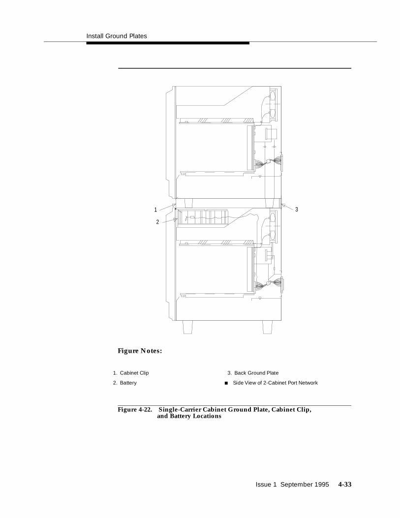
Install Ground Plates
Issue 1 September 1995 4-33
Figure Notes:
Figure 4-22. Single-Carrier Cabinet Ground Plate, Cabinet Clip,and Battery Locations
1
2
3
1. Cabinet Clip
2. Battery
3. Back Ground Plate
■ Side View of 2-Cabinet Port Network

Install and Connect the Cabinets
4-34 Issue 1 September 1995
Install Cable Clamps
At the back of the cabinets, on each ground plate, install two cable clamps using the screws provided (see Figure 4-23). These clamps hold the 25-pair input/output or cross-connect field cables in place.
Figure 4-23. Location of Cable Clamps
4 5
2
1
3
Figure Notes:
1. Cable Clamp
2. Cable Slack Manager
3. Switch Cabinet
4. Cabinet Trough for Port Cables
5. Spare Center Troughs

Install Front Plates
Issue 1 September 1995 4-35
Install Front Plates
The front plates provide electromagnetic radiation and radio frequency (RF) shielding and earthquake protection.
If you do not have a requirement for electromagnetic radiation shielding, radio frequency shielding, or earthquake protection, use the cabinet clips as described in this section.
Install Front Plates on Systems withEarthquake Protection
Refer to Appendix B to install the front plates to help provide earthquake protection and radiation shielding.
Front plates are used in place of cabinet clips (as described in Appendix B), for earthquake protection.
Install Cabinet Clip On Systems withoutEarthquake Protection
A cabinet clip is required between each cabinet to stabilize the cabinets.
Figure 4-24. Cabinet Clip
At the front of the cabinets, install a cabinet clip (Figure 4-24) between each cabinet by hooking the clip into the slot of the upper cabinet and snapping the straight leg of the clip into the slot on the lower cabinet (see Figure 4-25).
1

Install and Connect the Cabinets
4-36 Issue 1 September 1995
Figure 4-25. Location of Cabinet Clips
1
2
3
4
5
1. Port Cabinet D
2. Port Cabinet C
3. Cabinet clips
4. Port Cabinet B
5. Basic Control Cabinet A
Figure Notes:

Issue 1 September 1995 5-1
5Install Telecommunications Cabling
This chapter describes how to install telecommunications cables and cross-connect equipment.
The specific equipment being installed varies on what was ordered for your site. Use the material presented in this chapter as an example.
Install the Cross-Connect Field
This section describes how to connect to the cross-connect field.
Typical Cross-Connect Field Using110-Type Hardware
The cross-connect field is normally located directly behind the switch cabinet. Figure 5-1 shows a typical cross-connect field installation using 110A-type terminal blocks. Allow at least 3 feet (1 meter) between the back of cabinet and the 110-type hardware.

Install Telecommunications Cabling
5-2 Issue 1 September 1995
Figure 5-1. Typical Cross-Connect Field Installation: 110A-Type Terminal Blocks
3
2
87
4
5
5
5
5
1
6
1. D Ring
2. Trunk auxiliary field
3. Port distribution field
4. Station distribution field
5. Station cables
6. Switch cabinet
7. Z113A cable slack manager
8. 25-pair cable to switch cabinet
Figure Notes:

Issue 1 September 1995 5-3
In Figure 5-1, approximately 576 4-Pair or 768 3-Pair Station Capacity is illustrated.
Hardware Installation
These hardware installation instructions are written so one system technician can install the following equipment:
■ Cross-connect field
■ Cable slack managers
■ Sneak current protector (507B)
The preferred cross-connect field location is directly behind the switch cabinet.
Install Cable Slack Managers
To install the cable slack managers (Figure 5-2), proceed as follows:
1. Place the Z113A cable slack manager against the wall under the cross-connect field, aligning the left side of the cable slack manager with the first terminal block of the trunk/auxiliary field.
2. Place the next cable slack manager beside the previous cable slack manager. Align the tabs and interlocks and snap the cable slack managers together.
3. Repeat Step 2 until all cable slack managers are installed.
NOTE:Nine holes (1/4-inch or 0.6 cm) are provided in a cable slack manager base for earthquake mounting. Also, if a cable slack manager base is mounted on an uneven floor, shims may be required to level it and insure proper fit of the covers. Holes are provided in the sides of the base for bolting cable slack managers together. Bolts and shims are not provided.
Route Cables from Cabinet to Cross-Connect Field
Use the following guidelines when routing cables from the cabinet to the cross-connect field.
■ When cable routing is to the top/bottom of the cross-connect field, each port cable is connected at the cabinet and routed along the front trough of the cable slack manager to the connecting/terminal block. The cable is then terminated.
■ Enough slack must be left at the cabinet end of the cable to allow for proper dressing of the cables (Figure 5-3).

Install Telecommunications Cabling
5-4 Issue 1 September 1995
■ Route the cable from the cabinet to the wall. Place the cable beside one of the rows of columns in the cable slack manager (see following note).
NOTE:Retainers mounted on the columns keep the cable from protruding above the top of the base of the cable slack manager.
■ Determine the length of the cable required to reach from the cable slack manager to the assigned connecting/terminal block.
■ The cable must be supported on the wall.
■ Cable slack is stored by coiling the cable around the columns in the cable slack manager. The first run should always go across the full length of the five columns in the cable slack manager.
■ Connect the cable to the assigned connecting/terminal block.
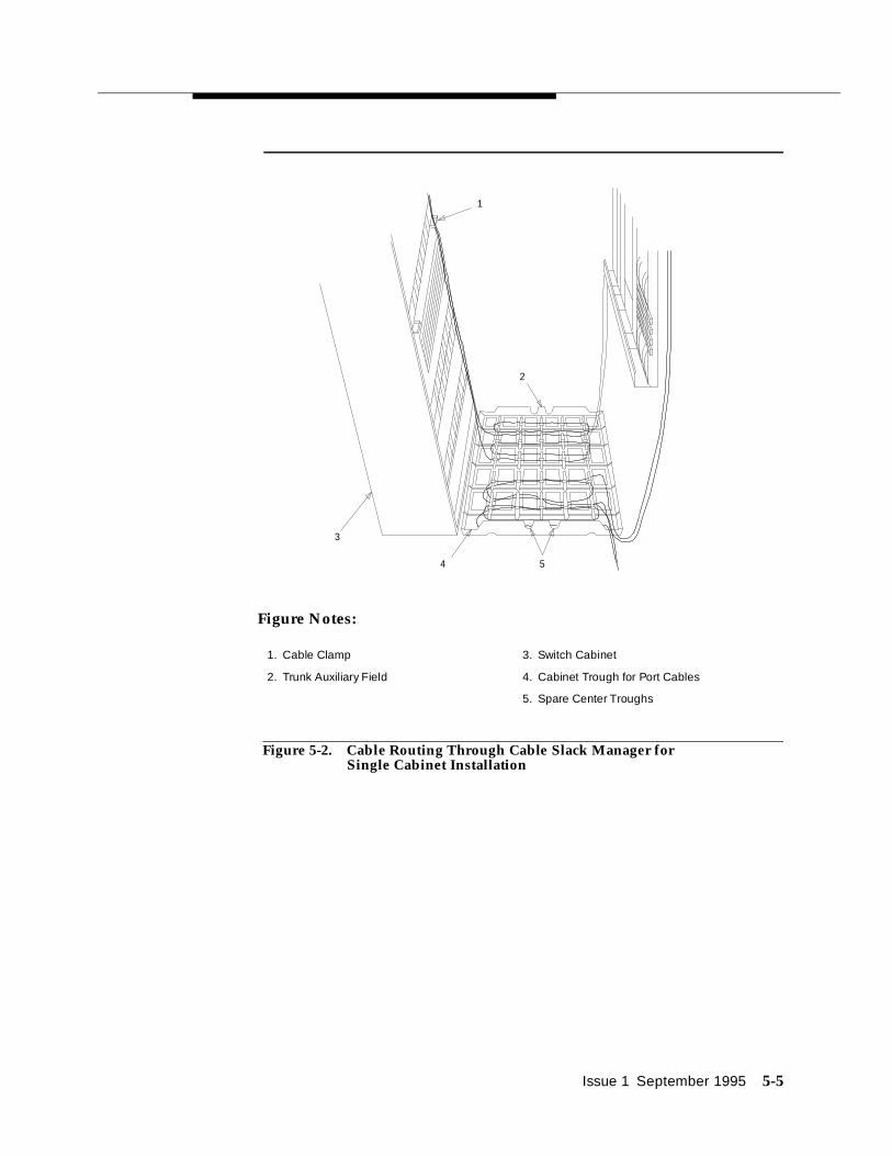
Issue 1 September 1995 5-5
Figure 5-2. Cable Routing Through Cable Slack Manager for Single Cabinet Installation
4 5
2
1
3
1. Cable Clamp
2. Trunk Auxiliary Field
3. Switch Cabinet
4. Cabinet Trough for Port Cables
5. Spare Center Troughs
Figure Notes:

Install Telecommunications Cabling
5-6 Issue 1 September 1995
Figure 5-3. Typical Port Cable Installation at Switch Cabinet
Connect Control Carrier Outputs Cable
Plug the connector cable in the AUX connector on the rear of the control carrier. Route the connector cable through the cable slack manager to the assigned connecting block in the yellow field of the trunk/auxiliary field.
Refer to Table 9-9 for pinout information.
The output wiring connections for the Initialization Administration System (INADS) trunk interface are described in "Install Initialization and Administration System (INADS) Interface" on page 9-21.
3
4
4
4
4
4
4
5 5
1
2
1. B25A cables
2. Loop and Drape Excess Fibre-Optic Cable. Do Not Route Fibre-Optic Cable and B25A Cables Together.
3. Fibre-Optic Cable Sheath
4. Port Cabinet
5. Control cabinet
Figure Notes:
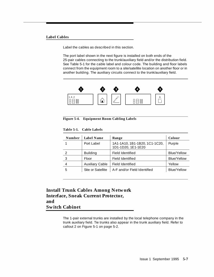
Issue 1 September 1995 5-7
Label Cables
Label the cables as described in this section.
The port label shown in the next figure is installed on both ends of the25-pair cables connecting to the trunk/auxiliary field and/or the distribution field. See Table 5-1 for the cable label and colour code. The building and floor labels connect from the equipment room to a site/satellite location on another floor or in another building. The auxiliary circuits connect to the trunk/auxiliary field.
Figure 5-4. Equipment Room Cabling Labels
Install Trunk Cables Among Network Interface, Sneak Current Protector, and Switch Cabinet
The 1-pair external trunks are installed by the local telephone company in the trunk auxiliary field. Tie trunks also appear in the trunk auxiliary field. Refer to callout 2 on Figure 5-1 on page 5-2.
Table 5-1. Cable Labels
Number Label Name Range Colour
1 Port Label 1A1-1A10, 1B1-1B20, 1C1-1C20, 1D1-1D20, 1E1-1E20
Purple
2 Building Field Identified Blue/Yellow
3 Floor Field Identified Blue/Yellow
4 Auxiliary Cable Field Identified Yellow
5 Site or Satellite A-F and/or Field Identified Blue/Yellow
1 A A2
3 4 51 2

Install Telecommunications Cabling
5-8 Issue 1 September 1995
Route the incoming trunk cables through the lightning protector and then to the Sneak Current Protector (507B). The 25-pair cable then goes through the trunk cross-connect field and then to the port.

Issue 1 September 1995 6-1
6Install Generic 3 Management Terminal
This chapter contains Generic 3 Management Terminal (G3-MT) requirements. Also detailed is:
■ How to directly connect a terminal to the switch
■ How to set up the terminal
■ Alternative procedure to remotely connect a terminal to the switch.
The Generic 3 Management Terminal (G3-MT) shipped with the system is a 715 Management Terminal (715 MT). See the documentation packed with the terminal for information not contained in this chapter.
Generic 3 Management Terminal(G3-MT) Requirements
One Generic 3 Management Terminal (G3-MT) should be located in the same equipment room as the cabinet or in sight of the cabinet and must be within 50 feet (18 meters) of the cabinet. It is strongly recommended the terminal be connected directly to the switch cabinet with the shortest possible cable. If desired, another terminal can be connected remotely.
! CAUTION:When the terminal is being installed to support a DC-powered system or a system requiring electromagnetic shielding, a 116A Electronic Industries Association (EIA) ground isolator (comcode 106 005 242) must be installed at the back of the switch cabinet as shown in the schematic in Figure 6-2 and as described in this chapter.
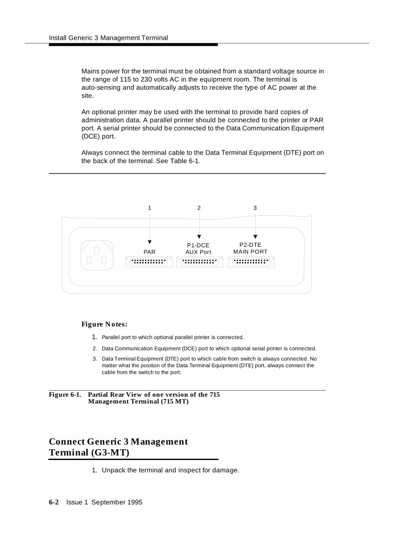
Install Generic 3 Management Terminal
6-2 Issue 1 September 1995
Mains power for the terminal must be obtained from a standard voltage source in the range of 115 to 230 volts AC in the equipment room. The terminal is auto-sensing and automatically adjusts to receive the type of AC power at the site.
An optional printer may be used with the terminal to provide hard copies of administration data. A parallel printer should be connected to the printer or PAR port. A serial printer should be connected to the Data Communication Equipment (DCE) port.
Always connect the terminal cable to the Data Terminal Equipment (DTE) port on the back of the terminal. See Table 6-1.
Figure Notes:
1. Parallel port to which optional parallel printer is connected.
2. Data Communication Equipment (DCE) port to which optional serial printer is connected.
3. Data Terminal Equipment (DTE) port to which cable from switch is always connected. No matter what the position of the Data Terminal Equipment (DTE) port, always connect the cable from the switch to the port.
Figure 6-1. Partial Rear View of one version of the 715 Management Terminal (715 MT)
Connect Generic 3 Management Terminal (G3-MT)
1. Unpack the terminal and inspect for damage.
PARP1-DCEAUX Port
P2-DTEMAIN PORT
321

Connect Generic 3 Management Terminal (G3-MT)
Issue 1 September 1995 6-3
2. If you have a DC-powered switch control cabinet or if you need electromagnetic shielding, locate the 116A Electronic Industries Association (EIA) Ground Isolator (comcode 106 005 242) and install it in the TERMINAL connector on the rear of the switch control cabinet (for standard reliability, unduplicated systems); or in the DUPLICATION OPTION TERMINAL connector (for high and critical reliability, duplicated systems), and skip to Step 4 below. See Figure 6-3 for the position of these two connectors at the rear of the switch cabinet.
If you do not have a DC-powered switch control cabinet, go directly to Step 3 below.
3. Use an M25B Electronic Industries Association (EIA) shielded cord (cable code H600-426) or an equivalent to connect between the terminal DTE connector and the TERMINAL connector (unduplicated systems) or the DUPLICATION OPTION TERMINAL (duplicated systems) on the rear of the switch control carrier and skip to Step 5 below.
4. For DC-powered cabinets or for electromagnetic shielding, use an M25B (Electronic Industries Association) shielded cord (cable code H600-426) or an equivalent to connect between the terminal DTE port and a 116A Electronic Industries Association (EIA) ground isolator (comcode 106 005 242) mounted in the TERMINAL connector (unduplicated systems) or the DUPLICATION OPTION TERMINAL connector (duplicated systems) position on the rear of the control carrier.
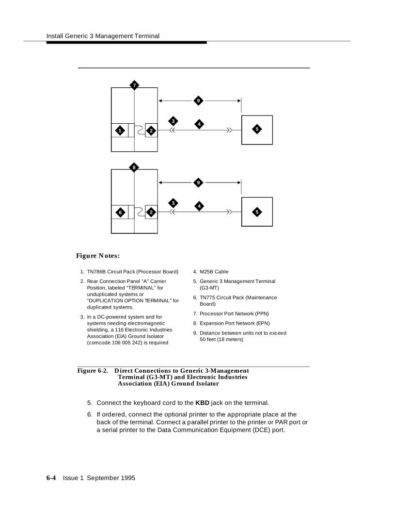
Install Generic 3 Management Terminal
6-4 Issue 1 September 1995
Figure 6-2. Direct Connections to Generic 3-Management Terminal (G3-MT) and Electronic Industries Association (EIA) Ground Isolator
5. Connect the keyboard cord to the KBD jack on the terminal.
6. If ordered, connect the optional printer to the appropriate place at the back of the terminal. Connect a parallel printer to the printer or PAR port or a serial printer to the Data Communication Equipment (DCE) port.
7
3
3
4
4
9
9
5
5
1 2
26
8
1. TN786B Circuit Pack (Processor Board)
2. Rear Connection Panel “A” Carrier Position, labeled “TERMINAL” for unduplicated systems or “DUPLICATION OPTION TERMINAL” for duplicated systems.
3. In a DC-powered system and for systems needing electromagnetic shielding, a 116 Electronic Industries Association (EIA) Ground Isolator (comcode 106 005 242) is required
4. M25B Cable
5. Generic 3 Management Terminal (G3-MT)
6. TN775 Circuit Pack (Maintenance Board)
7. Processor Port Network (PPN)
8. Expansion Port Network (EPN)
9. Distance between units not to exceed 50 feet (18 meters)
Figure Notes:

Connect Generic 3 Management Terminal (G3-MT)
Issue 1 September 1995 6-5
7. Connect AC power cord of the terminal to the selected AC receptacle in the equipment room and turn on the terminal.
Figure 6-3. Duplication Optional Terminal and Terminal Connectors on the Control Cabinets
Figure 6-3 shows the two possible positions on the back of the switch control cabinet for connecting the M25B cord between the switch and the terminal; or, for DC powered systems and for electromagnetic shielding, for installing the 116A Electronic Industries Association (EIA) Ground Isolator: the DUPLICATION OPTION TERMINAL connector for high and critical reliability (duplicated) systems in the top illustration and the TERMINAL connector for standard reliability (unduplicated) systems in the bottom illustration.
TERMINAL TERMINAL
DUPLICATION
OPTIONPROCESSOR
INTERFACE
DATA
COMMUNICATIONS
EQUIPMENT
TERMINAL TERMINAL
DUPLICATION
OPTIONPROCESSOR
INTERFACE
DATA
COMMUNICATIONS
EQUIPMENT

Install Generic 3 Management Terminal
6-6 Issue 1 September 1995
Set Up G3 Management Terminal (G3-MT)
Use the following procedures to set up the 715 Management Terminal options:
NOTE:These procedures may change as the model of 715 Management Terminal (G3-MT) shipped with DEFINITY System Generic 3 changes. Consult the documentation shipped with the terminal for set up instructions.
1. Hold down the CTRL key while pressing F1 and verify the terminal setup screen is shown.
Function keys (F1, etc.) are located at the top of the keyboard of the terminal. Lighted rectangles (windows) appear at the bottom of the screen and correspond to the function keys across the top of the keyboard.
2. Press F7 to make sure the default values are set.
3. Using the up/down arrow keys on the keypad, position the cursor at the Keyboard Options (per window) field and press RETURN.
4. Using the up/down arrow keys on the keypad, position the cursor at the Enter Key field. Then under Primary/Window 1 press the ESC key, then hold down the SHIFT key and type S and then B. This will enter escapeSB in this field.
5. Press F5-SAVE to save the changes then press F1 SETUP MENU and exit the Setup Menu screen.
Table 6-1. Required Settings for 715 Management Terminal to Communicate with Switch
Terminal Option Value
Font Size Large (default)
Autowrap Off (default)
Baud Rate 9600 (default)
Stop Bit 1 (default)
Data Bits 7 (default)
Parity Space (default)
Check Parity Yes (default)
Transmission Flow Control X on, X off (default)
Enter Key escapeSB (must be set)

Remotely Connect Generic 3 Management Terminal (G3-MT)
Issue 1 September 1995 6-7
Remotely Connect Generic 3 Management Terminal (G3-MT)
A secondary (and optional) terminal used for purposes other than maintenance can be installed at some distance from the switch. Typical remote connections are shown in the schematic in Figure 6-4 below.
Figure 6-4. Typical Remote Connections from Generic 3 Across Public Network to Terminal and Other Remote Devices
12
3
4
5
6
57 8
9
11
12
1331415
5439
10
13
16
1. External modem pool
2. 7400A data module
3. Line Cord
4. Cross Connect Field
5. B25A Cable
6. TN754 Circuit Pack
7. Public Network
8. 103A or Modular Wall Jack
9. Modem
10. When a DB9 is used on the back of a personal computer (PC), use ED3-1-70, G115 to convert DB9 to DB25.
11. Call Detail Recording Utility, CAS+, Property Management System, Basic Call Management System, Remote Management Terminal, System Journal Printers, Cost Allocator
12. Remote Management Terminal or Monitor 1
13. M25A Cable
14. This circuit pack can be any of the following: TN747, TN753, TN760, TN767, TN464, TN2147, TN465, etc.
15. This circuit pack can be any analog circuit pack: TN769, TN742, TN746, TN2183 etc.
16. DEFINITY System Generic 3 switch
Figure Notes:

September 1995 Issue 1 7-1
7Activate the System
This chapter contains procedures for activating the system and bringing the switch up to a non-alarm (no red lights) state. This chapter details:
■ Powering up the switch
■ Installing translation flash-memory card
■ Powering up AC-powered switch
■ Powering up DC-powered switch
■ Verifying messages on management terminal
■ Logging in to the system
■ Setting required country options
■ Changing craft password
■ Setting date and time
■ Setting system maintenance parameters
■ Saving translations
After the system is activated, the telephones and other equipment need to be installed (see Chapter 9, "Install and Wire Telephones and Other Equipment"). The system is administered by adding the customer data to match the wiring, telephones, and other equipment (see the reference to the book at the end of Chapter 9, "Install and Wire Telephones and Other Equipment"). The telephones and other equipment are tested (see Chapter 10, "Test Telephones and Other Equipment").
! CAUTION:While performing these procedures, you may need to reseat circuit packs. To prevent damage from static electricity, always wear an Electromagnetic

Activate the System
7-2 September 1995 Issue 1
Compatibility (EMC) wrist strap (comcode 900 698 226) when handling circuit packs or other switch components.
Power Up Switch
To power up the switch, do the following:
Install Translation Flash-Memory Card
1. Verify the write switch on the white Translation Flash-Memory Card (Translation Card) shipped with the system is positioned so the card can be written. The write switch is shown in the correct position in Figure 7-1.
2. Install the Translation Card in the TN777B network control circuit pack. Insert the card into the slot in the direction indicated by the arrow on the card’s label as shown in Figure 7-1.
Figure Notes:
1. Insert card in direction of arrow into the slot.
2. Slot on TN777B circuit pack
3. Write switch positioned correctly
Figure 7-1. Write Switch on DEFINITY Memory Card
1
2
INSERT
Def
inity
Mem
ory
Car
d
3

Power Up Switch
September 1995 Issue 1 7-3
Power up AC-Powered Switch
1. Ensure the associated circuit breakers on the AC power panel are ON.
NOTE:If the system is configured for High or Critical Reliability, power-up the Expansion Port Network (EPN) cabinet first, then the Processor Port Network (PPN) cabinet. Always power up the Control Cabinet last in any multi-cabinet configuration.
2. At the rear of each cabinet, set the circuit breaker to ON. Go to ‘‘Verify Messages.’’
NOTE:This action starts the system initialization and test. All red lights on the circuit packs go on and then off.
Power up DC-Powered Switch
1. At the DC Battery Cabinet, set circuit breaker to ON.
NOTE:If the system is configured for High or Critical Reliability, power-up the Expansion Port Network (EPN) cabinet first, then the Processor Port Network (PPN) cabinet. Always power up the Control Cabinet last in any multi-cabinet configuration.
2. At DC Power Cabinet, set the circuit breaker(s) on the associated rectifiers ON.
3. At the rear of each Power Distribution Unit, set the circuit breaker to ON.
NOTE:This action starts the system initialization and test. All red lights on the circuit packs go on and then off. Some red lights may come back on in a few seconds or a few minutes and will be turned off by other procedures in this chapter.
Verify Messages on Terminal
1. After several minutes, verify all tests pass.
NOTE:If any of the terminal messages indicate a test has failed or the message ‘‘spe down mode ’’ is displayed, refer to DEFINITY Communications System Generic 1 and Generic 3i/s/vs Maintenance, 555-204-105, to clear the trouble, or call your AT&T representative.

Activate the System
7-4 September 1995 Issue 1
Screen 7-1. Typical Turn-On Messages for Systems with FLASH Memory
2. About 2 minutes after REBOOT PERFORMED is displayed, verify the terminal screen displays:
Login :
NOTE:Most red lights will come on and go off again at this point. Some red lights will stay on until the country options are administered in the next pages.
Introduction to Terminal Screens and Commands
Screens
The system is administered using screens displayed on the terminal. The screens are used to add, change, display, list data, and to remove system and telephone features. To access a screen, enter a valid system command in response to the command: prompt.
TN786 FLMM Release 1.8.0 INVOKING EMERGENCY TRANSFER ROM CHECKSUM TEST ( = 9CAE ) PASSED SOFT INT TEST PASSED NMI TEST PASSED READ_WRITE MEMORY PASSED MEMORY BOARD 1 PARITY BIT TEST PASSED MEMORY FUNCTIONAL TEST PASSED FLASH TEXT CHECKSUM ( = EF3E ) PASSED RESET 4 (REBOOT) PERFORMED

Log in to the System
September 1995 Issue 1 7-5
Commands
System commands are standard words and phrases instructing the switch to perform a specific function. The commands are arranged in hierarchy of keywords; that is, enter one command to take you to a different level. The commands contain three parts: ACTION, OBJECT, and QUALIFIER.
■ ACTION is the first part of the command. When command: appears on the screen. The ACTION specifies the operation you want to do. Examples of permissible entries include add, duplicate, change, remove, display, list, and save.
■ OBJECT is the second part of the command and specifies the particular object you want to administer. Typical entries are hunt-group, coverage path, and station.
■ QUALIFIER is the last part of the command. It is one or more words or digits used to further identify or complete the OBJECT. For example, hunt group 15 or station 3600, where 15 and 3600 are qualifiers.
An example of the command line required to add a station with extension number 1234 is add station 1234 . In this example, add is the ACTION, station is the OBJECT, and 1234 is the QUALIFIER. In the command line, spaces are required between the ACTION, OBJECT, and QUALIFIER.
To save time, enter enough letters for each part of the command to make it unique. For example, if you want to enter the command change system-parameters country-options , typing cha sys coun is acceptable. However, typing the entire command will always work.
NOTE:The craft login may not be allowed to perform some of the steps needed to initialize the switch. If access is denied to some of these procedures, contact your AT&T representative for assistance.
Getting Help
Use the HELP key for a list of options and the CANCEL key to back out of any command.
Log in to the System
To log on the system, do the following:
1. Verify the screen displays:
Login:
2. Type craft and press ENTER.
Activate the System
7-6 September 1995 Issue 1
3. Verify the screen displays:
password :
4. Type crftpw and press ENTER. For security reasons, the password is not displayed as it is typed. The system verifies a valid login and password name were entered. If an invalid login or password name was entered, the screen displays:
login incorrect:
In this case, repeat the procedure using the correct login and matching password.
If the system recognizes the login and password name, the screen will display the software version.
5. Verify the screen display is similar to:
Terminal Type (513, 715, 4410, 4425, VT220): [513]
6. Type the number of your management terminal and press ENTER.
7. Verify the screen displays:
command:
Set Required Country Options
Certain country options need to be set to turn red failure indication lights off on the circuit packs.
1. Verify the screen displays:
command:
2. Type change system-parameters country options and press ENTER.
The following screen is displayed. The cursor is set on Companding Mode line.
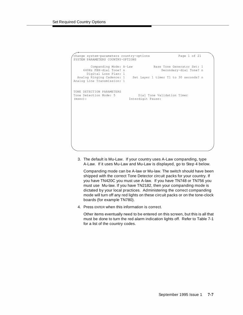
Set Required Country Options
September 1995 Issue 1 7-7
3. The default is Mu-Law. If your country uses A-Law companding, type A-Law. If it uses Mu-Law and Mu-Law is displayed, go to Step 4 below.
Companding mode can be A-law or Mu-law. The switch should have been shipped with the correct Tone Detector circuit packs for your country. If you have TN420C you must use A-law. If you have TN748 or TN756 you must use Mu-law. If you have TN2182, then your companding mode is dictated by your local practices. Administering the correct companding mode will turn off any red lights on these circuit packs or on the tone-clock boards (for example TN780).
4. Press ENTER when this information is correct.
Other items eventually need to be entered on this screen, but this is all that must be done to turn the red alarm indication lights off. Refer to Table 7-1 for a list of the country codes.
change system-parameters country-options Page 1 of 21SYSTEM PARAMETERS COUNTRY-OPTIONS
Companding Mode: A-Law Base Tone Generator Set: 1 440Hz PBX-dial Tone? n Secondary-dial Tone? n Digital Loss Plan: 1 Analog Ringing Cadence: 1 Set Layer 1 timer T1 to 30 seconds? nAnalog Line Transmission: 1
TONE DETECTION PARAMETERSTone Detection Mode: 5 Dial Tone Validation Timer (msec): Interdigit Pause:

Activate the System
7-8 September 1995 Issue 1
5. If all the red lights do not go off, reseat (unplug and reinsert) any purple-labeled circuit packs displaying red lights.
! CAUTION:To avoid a disk crash, never reseat the DEFINITY AUDIX System without first shutting it down. Shut down the DEFINITY AUDIX System (and allow the disk to completely spin down) before unplugging the DEFINITY AUDIX assembly. See Appendix C, "DEFINITY AUDIX System Power Procedures" for the procedure for manually shutting down and powering up DEFINITY AUDIX System.
! CAUTION:Before attempting to reseat white-labeled control circuit packs or the purple-labeled tone detector/generator circuit pack (in the single-carrier cabinet only), first power down the switch.
6. If the red lights still do not go off, read the note below and then refer to DEFINITY Communications System Generic 1 and Generic 3i/s/vs Maintenance, 555-204-105, to resolve the trouble, if necessary.
NOTE:Ignore the red alarm indication light on the TN767 or TN464 DS1 circuit pack until after the Digital Service Level 1 (DS1) circuit pack is administered.
Table 7-1. Country Codes
Country Country Code Country Country Code
global 0 Spain 11
USA 1 France 12
Australia 2 Germany 13
Japan 3 Czechoslovakia 14
Italy 4 Russia 15
The Netherlands 5 Argentina 16
Singapore 6 Greece 17
Mexico 7 China 18
Belgium 8 Hong Kong 19
Saudi Arabia 9 Thailand 20
United Kingdom 10 Macedonia 21

Change Craft Password
September 1995 Issue 1 7-9
Alarms will appear in the Alarm Log when power is applied to the system before all equipment connecting to port circuit packs is installed. Normally, some alarms will be logged when power is applied to the system, but should be resolved quickly. If no equipment is connected to the port circuit packs, alarms associated with these ports can take up to four hours to log, but will clear automatically after all equipment is installed and operating correctly.
Change Craft Password
The password for the craft login must be changed by the installing technician to prevent unauthorized administration changes.
! CAUTION:After the ‘‘craft’’ password is changed, the new password must be safeguarded so no unauthorized administration changes can be made. This password MUST NOT BE REVEALED to the customer or to any unauthorized person.
Passwords are changed using the Change Password Screen (see Screen 7-2). To change the ‘‘craft’’ password, perform the following.
1. Verify the screen displays:
command:
2. Type change password craft . Press ENTER.

Activate the System
7-10 September 1995 Issue 1
Screen 7-2. Typical Change Password Screen
3. Verify the screen displays Change Password Screen.
Cursor is positioned on ‘‘Password for Login Making Change: ”
4. Type the password assigned to the craft login (assigned as crftpw when system is shipped) and press ENTER.
Cursor is positioned on ‘‘Login’s Password :’’.
5. Enter selected new password (see note below).
NOTE:Valid passwords consist of a combination of from four to eleven alpha or numeric characters. At least one letter and one number must be used in each password.
6. Press ENTER.
Cursor is positioned on ‘‘Reenter Login’s Password :’’.
7. Type new password again.
8. Press ENTER.
9. Verify the screen displays:
command successfully completed
command:
change password craft Page 1 of 1 PASSWORD ADMINISTRATION
Password For Login Making Change:
LOGIN BEING CHANGEDLogin Name: craft
LOGIN’S PASSWORD INFORMATIONLogin’s Password:Reenter Login’s Password:

Set Date and Time
September 1995 Issue 1 7-11
Set Date and Time
The system date and time are set using the Set Date and Time Screen (see Screen 7-3). This screen is displayed on the terminal screen and is changed with the terminal keyboard. To set the system time and date, perform the following:
1. Verify the screen displays:
command:
2. Type set time . Then press ENTER.
3. Verify the screen displays Set Date and Time Screen (shown below).
Cursor is positioned on Day of the Week: field.
Screen 7-3. Typical Date and Time Screen
4. Type day of week in English (Sunday through Saturday) and press TAB to move to next field. See Table 7-2 for English day of the week names.
set time Page 1 of 1 DATE AND TIME DATE Day of the Week: _________ Month: __________ Day of the Month: __ Year: ____ TIME Hour: __ Second: xx Minute: __

Activate the System
7-12 September 1995 Issue 1
Cursor is positioned on Month: field.
5. Type current month in English (January through December) and press TAB to move to next field. See Table 7-3 for English month names.
Cursor is positioned on Year: field.
Cursor is positioned on Day of the Month: field.
Table 7-2. English Day of the Week Names
Day Number Day Name
1 Sunday
2 Monday
3 Tuesday
4 Wednesday
5 Thursday
6 Friday
7 Saturday
Table 7-3. English Month Names
Month Number English Month Name
1 January
2 February
3 March
4 April
5 May
6 June
7 July
8 August
9 September
10 October
11 November
12 December

Set Date and Time
September 1995 Issue 1 7-13
6. Type day of month (1 through 31) and press TAB to move to next field.
Cursor is positioned on Year: field.
7. Type current year (for example, 1995) and press TAB to move to next field.
Cursor is positioned on Hour: field.
8. Type current hour for 24-hour clock (see Table 7-4) and press TAB to move to the next field.
Cursor is positioned on Minute: field.
9. Type current minute (0 through 59).
Seconds cannot be set.
10. Press ENTER when the information is correct..
1. Verify the screen displays:
‘‘command successfully completed ’’
‘‘command: ’’
2. Type display time , and press ENTER to verify date/time data.
Table 7-4. Conversion to 24-Hour Clock
Standard Time Standard Time
12-Hour 24-Hour 12-Hour 24-Hour
12:00 midnight 0000 12:00 noon 1200
1:00 am 0100 1:00 pm 1300
2:00 am 0200 2:00 pm 1400
3:00 am 0300 3:00 pm 1500
4:00 am 0400 4:00 pm 1600
5:00 am 0500 5:00 pm 1700
6:00 am 0600 6:00 pm 1800
7:00 am 0700 7:00 pm 1900
8:00 am 0800 8:00 pm 2000
9:00 am 0900 9:00 pm 2100
10:00 am 1000 10:00 pm 2200
11:00 am 1100 11:00 pm 2300

Activate the System
7-14 September 1995 Issue 1
NOTE:The Set Date and Time Screen is displayed showing all data entered in the previous steps followed by:
command:
Set System Maintenance Parameters
NOTE:If you do not have a TN778 circuit pack, skip this procedure and proceed to "Save Translations" on page 7-15.
1. Verify the terminal screen displays:
command:
2. Type change system-parameters maintenance and press ENTER.
NOTE:Verify the screen displays Maintenance-Related System Parameters Screen (see Screen 7-4). The screen displays the default values and the cursor is positioned on Product Identification: line.
Screen 7-4. Typical Display System-Parameters Maintenance Screen (Page 1)
display system-parameters maintenance Page 1 of 2 MAINTENANCE-RELATED SYSTEM PARAMETERS OPERATIONS SUPPORT PARAMETERS Product Identification: __________ OSS Telephone Number: __________ Alarm Origination Activated? n Cleared Alarm Notification? n Restart Notification? n Test Remote Access Port? n CPE Alarm Activation Level: none Packet Bus Activated? n Customer Access to INADS port? n SCHEDULED MAINTENANCE Start Time: 01 : 00 Daily Maintenance: dail y Save Translation: dail y Control Channel Interchange: no System Clocks Interchange: no SPE Interchange: no EXP-LINK Interchange: no

Save Translations
September 1995 Issue 1 7-15
3. Move the cursor by pressing TAB to move down the screen from field to field and enter y in the Packet Bus Activated? field to indicate you have a TN778 circuit pack.
This is the only field needing change on this screen to turn the red lights off.
4. Press ENTER when the information is correct.
5. Verify the screen displays:
command successfully completed
command:
Save Translations
The save translation command copies the current system translations onto the translation card. For standard-reliability systems, one translation card plus one backup are required. For high or critical-reliability systems, two translation cards plus two backups are required.
! CAUTION:Do not attempt to save translations on the orange-labeled, 10 MB memory card. Use the white translation card!
The following procedure can be used to save system translations on the original card(s) and can also can be used to make a backup card or cards:
1. Verify the screen displays:
command:
2. Type save translation and press ENTER.
3. After several minutes, the screen displays something like this:

Activate the System
7-16 September 1995 Issue 1
Screen 7-5. Typical Save Translation Screen
4. Verify a 0 is displayed in the Error Code column for each switch processing element in the system. A 0 indicates the save translation was successfully completed for the translation card. If a 0 did not appear, the save translation did not complete. Record the ‘‘error code number’’ and the ‘‘error message’’ and notify your AT&T representative.
5. Remove the original translation card(s) from the TN777B(s) and replace it or them with backup card(s).
6. Repeat Steps 1 through 4 for the backup card(s).
7. Remove the backup translation card(s) from the TN777B and replace it or them with the original translation card(s).
8. Label the backup card(s) with the date and time of the backup. A special notation should be put on the cards to clearly distinguish them from other such devices.
9. Store the backup in a secure place.
save translation SPE A SAVE TRANSLATIONProcessor Command Completion Status Error CodeSPE_A Success 0
SPE_B Success 0
Command successfully completedcommand:

Save Translations
September 1995 Issue 1 7-17
Logoff
Log off the system to prevent unauthorized changes of the data. To log off:
1. Type logoff and press ENTER.
2. Verify the screen displays:
Login:
NOTE:The login prompt indicates you have logged off the system and it is ready for another person to log on.

Issue 1 September 1995 8-1
8Test the System
The following tests provide verification of the Time Division Multiplexing (TDM) cables and terminators, and fibre-optic inter-cabinet cables (ICC). If a FAIL Result code is seen or other problems are indicated, check these cables. If problems persist, refer to the U.S. English book, DEFINITY Communications System Generic 1 and Generic 3i Maintenance, 555-104-205.
The status of the system should be reviewed first, followed by testing the tone-clock, Time Division Multiplexing (TDM) bus, and duplication link in the Processor Port Network (PPN). Then test expansion interfaces, tone-clock(s), Time Division Multiplexing (TDM) buses, and duplication in the Expansion Port Networks (EPNs).
NOTE:Circuit pack positions are usually given by cabinet, carrier (within cabinet), and slot (within carrier). They may also be given by port (within slot). The term “cabinet” refers to a stack of single carrier cabinets making up one port network. A port network is defined as a group of cabinets connected together with one Time Division Multiplexing (TDM) bus.
Check the System Status for Each Cabinet
The system status may suggest problem areas. Specific tests later provide more specific diagnostic information.
1. Verify the terminal screen displays:
command:
2. Type status system all-cabinets and press ENTER.

Test the System
8-2 Issue 1 September 1995
3. Verify the screen displays system status screens similar to the example shown below:
Screen 8-1. Example System Status Screen for Cabinet 1
NOTE:In the first section of the report, all Tone-Clocks should report a SERVICE STATE of in .
NOTE:In the second section of the report, all Time Division Multiplexing (TDM) buses should report a SERVICE STATE of in .
NOTE:In the third section of the report, all expansion links should report a SERVICE STATE of in , and, under EXP-LINK, the cabinet/carrier/slot numbers for the fiber optic cables are listed. For example, 01A01 in Screen 8-1 refers to cabinet 01, carrier A, and slot 01.
NOTE: Refer to the U.S. English book, DEFINITY Communications System Generic 1 and Generic 3i Maintenance, 555-104-205, for a detailed interpretation of this screen.
status system all-cabinets Page 1 of 3 SPE A SYSTEM STATUS CABINET 1
SELECT SPE ALARMS TONE/ SERVICE SYSTEM SYSTEM SPE MODE SWITCH MAJOR MINOR CLOCK STATE CLOCK TONE 1A active auto 1 0 1A in standby standby 1B maint/init auto 1 0 1B in active active
SERVICE CONTROL DEDICATED SERVICE BUS ALARMS BUS OPEN BUS TDM STATE CHANNEL TONES PKT STATE MAJOR MINOR FAULTS LEADS 1A in y n 1 1B in n y
EMERGENCY SELECT SERVICE CABINET TRANSFER SWITCH EXP-LINK STATE MODE TYPE 1A auto-on 01A01-02A01 in standby MCC 1B auto-on 01B01-02B02 in active

Check the System Status for Each Cabinet
Issue 1 September 1995 8-3
Screen 8-2. Example System Status Screen for Cabinet 2
NOTE:See the notes associated with Screen 8-1 on the previous page.
status system all-cabinets Page 2 of 3 SPE A SYSTEM STATUS CABINET 2
SELECT SPE ALARMS TONE/ SERVICE SYSTEM SYSTEM SPE MODE SWITCH MAJOR MINOR CLOCK STATE CLOCK TONE 1A active auto 1 0 2A in active active 1B maint/init auto 1 0 2B in standby standby
SERVICE CONTROL DEDICATED SERVICE BUS ALARMS BUS OPEN BUS TDM STATE CHANNEL TONES PKT STATE MAJOR MINOR FAULTS LEADS 2A in y n 2 2B in n y
EMERGENCY SELECT SERVICE CABINET TRANSFER SWITCH EXP-LINK STATE MODE TYPE 2A auto-on 01A01-02A01 in standby MCC 01B01-02B02 in active

Test the System
8-4 Issue 1 September 1995
Screen 8-3. Example System Status Screen for Cabinet 3
NOTE:See the notes associated with Screen 8-1 on the previous page.
NOTE:In the example of Screen 8-3, cabinet 3 (the second Expansion Port Network (EPN)) is not connected to the system.
Check Circuit Pack Configuration
The list configuration report provides a list of circuit packs plugged into the system and recognized by the software.
1. Verify the screen displays:
command:
2. Type list configuration all and press ENTER.
3. Verify the screen displays list configuration screens similar to the example shown below. Check the report on the screen with the equipment installed and make sure the software is communicating with each circuit pack (except power supply circuit packs). Wait until after the diagnostic tests later in this chapter before attempting to correct any problems.
status system all-cabinets Page 3 of 3 SPE A SYSTEM STATUS CABINET 3
SELECT SPE ALARMS TONE/ SERVICE SYSTEM SYSTEM SPE MODE SWITCH MAJOR MINOR CLOCK STATE CLOCK TONE 1A active auto 1 0 3A 1B maint/init auto 1 0 3B
SERVICE CONTROL DEDICATED SERVICE BUS ALARMS BUS OPEN BUS TDM STATE CHANNEL TONES PKT STATE MAJOR MINOR FAULTS LEADS 3A 3B
EMERGENCY SELECT SERVICE CABINET TRANSFER SWITCH EXP-LINK STATE MODE TYPE 3A -

Check Circuit Pack Configuration
Issue 1 September 1995 8-5
4. Note any displays for boards that say in the VINTAGE column: BOARD NOT PRESENT or CONFLICT.
Screen 8-4. Example System Configuration Screen — Page 1
NOTE:Under Assigned Ports , a “u” indicates unassigned ports and a number indicates the port has been translated.
list configuration all Page 1 SPE B
SYSTEM CONFIGURATION
Board Assigned Ports Number Board Type Code Vintage u=unassigned t=tti
01A01 EXPANSION INTRFC TN570B 000001 01A03 DID TRUNK TN459 000004 u u u u u u u u 01A04 DID TRUNK TN436 000004 u u u u u u u u 01A07 TIE TRUNK TN439 000004 u u u u 01A09 ANNOUNCEMENT TN750 000007 01 02 03 04 05 06 07 08 09 10 11 12 13 14 15 16 01B01 EXPANSION INTRFC TN570 000009 01B02 TONE DETECTOR TN748D 000002 01 02 03 05 06 07 01B03 DATA LINE TN726 000012 u u u u u u u u 01B08 BRI LINE TN556B 000003 u u u u u u u u u u u u u u u u u u u u u u u u 01C01 ANALOG LINE TN746B 000006 u u u u u u u u u u u u u u u u
press CANCEL to quit -- press NEXT PAGE to continue

Test the System
8-6 Issue 1 September 1995
Screen 8-5. Example System Configuration Screen — Page 2
Page 2
SYSTEM CONFIGURATION
Board Assigned Ports Number Board Type Code Vintage u=unassigned t=tti
01C02 DIGITAL LINE TN754B 000001 u u u u u u u u 01C04 CO TRUNK TN747B 000012 u u u u u u u u 01C05 E&M TIE TRUNK TN437B 000001 u u u u 01C06 DS1 INTERFACE TN464D 000002 u u u u u u u u u u u u u u u u u u u u u u u u u u u u u u u u 01C08 DS1 INTERFACE TN464D 000002 u u u u u u u u u u u u u u u u u u u u u u u u u u u u u u u u 01C11 E&M TIE TRUNK TN458 000005 u u u u 01C12 CO TRUNK TN438B 000001 u u u u u u u u 01C13 CO TRUNK TN447 000003 u u u u u u u u
press CANCEL to quit -- press NEXT PAGE to continue

Check Circuit Pack Configuration
Issue 1 September 1995 8-7
Screen 8-6. Example System Configuration Screen — Page 3
list configuration all Page 3
SYSTEM CONFIGURATION
Board Assigned Ports Number Board Type Code Vintage u=unassigned t=tti
01C15 DS1 INTERFACE TN767 000017 u u u u u u u u u u u u u u u u u u u u u u u u 01C17 CALL CLASSIFIER TN744 000007 01 02 03 04 05 06 07 08 01C19 MAINTENANCE/TEST TN771D 000006 u 02 03 u 01C20 AUXILIARY TRUNK TN763D 000005 u u u u 02A01 EXPANSION INTRFC TN570B 000001 02A02 TONE DETECTOR TN748C 000005 01 02 03 05 06 07 02A03 DIGITAL LINE TN754 000010 u u u u u u u u 02A04 ANALOG LINE TN467 000003 u u u u u u u u 02A05 TIE TRUNK TN439 000004 u u u u 02A10 BRI LINE TN556 000009 u u u u u u u u u u u u u u u u u u u u u u u u
press CANCEL to quit -- press NEXT PAGE to continue

Test the System
8-8 Issue 1 September 1995
Screen 8-7. Example System Configuration Screen — Page 4
configuration all Page 4
SYSTEM CONFIGURATION
Board Assigned Ports Number Board Type Code Vintage u=unassigned t=tti
02B01 TONE/CLOCK TN780 000005 02B02 EXPANSION INTRFC TN570 000009 02B04 ANALOG LINE TN2135 000003 u u u u u u u u u u u u u u u u 02B06 DIGITAL LINE TN2181 000001 u u u u u u u u u u u u u u u u 01A DUPLICATION INTRFC TN772 000012 01A PROCESSOR TN786B 000004 01A MEMORY EXPANSION CPP1 000005 01A NETWORK CONTROL TN777B 000018 u u u u 01A TONE/CLOCK TN2182 000002 01 02 03 04 05 06 07 08 01B DUPLICATION INTRFC TN772 000013 01B PROCESSOR TN786B 000004 01B MEMORY EXPANSION CPP1 000005
press CANCEL to quit -- press NEXT PAGE to continue

Test Time Division Multiplexor (TDM) Bus in Processor Port Network (PPN)
Issue 1 September 1995 8-9
Screen 8-8. Example System Configuration Screen — Page 5
Test Time Division Multiplexor (TDM)Bus in Processor Port Network (PPN)
1. Verify the screen displays:
command:
2. Type test tdm port-network 1 and press ENTER.
3. Verify the screen displays the results of this test as shown in the example on the following page.
list configuration all SPE B
SYSTEM CONFIGURATION
Board Assigned Ports Number Board Type Code Vintage u=unassigned t=tti
01B NETWORK CONTROL TN777B 000018 u u u u 01B TONE/CLOCK TN2182 000002 01 02 03 04 05 06 07 08 02A MAINTENANCE TN775B 000001 02A TONE/CLOCK TN780 000005
Command successfully completed

Test the System
8-10 Issue 1 September 1995
Screen 8-9. Example Test Results for Time Division Multiplexing (TDM) Port Network 1
4. If the result is FAIL for any test, check the connectors of the Time Division Multiplexing (TDM) bus cables in Processor Port Network (PPN) 1.
Test Tone-Clock Boards
Testing the Tone-Clock board also detects problems with the Time Division Multiplexing (TDM) bus cables.
1. Verify the screen displays:
command:
2. Type test tone-clock 1a and press ENTER.
3. Verify the screen displays test results similar to the example shown on the following page:
test tdm port-network 1 SPE B
TEST RESULTS
Port Maintenance Name Alt. Name Test No. Result Error Code
PN 01A TDM-BUS 294 PASS PN 01A TDM-BUS 296 PASS PN 01A TDM-BUS 297 ABORT 1005 PN 01B TDM-BUS 294 PASS PN 01B TDM-BUS 296 ABORT 1005 PN 01B TDM-BUS 297 PASS
Command successfully completed
Command:

Test Switch Processing Element (SPE) Duplication Memory Shadowing Link
Issue 1 September 1995 8-11
Screen 8-10. Example Test Results for Tone-Clock 1A
Test Switch Processing Element (SPE)Duplication Memory Shadowing Link
For High and Critical Reliability systems, test the Switch Processing Element (SPE) duplication; memory shadowing link.
1. Verify the screen displays:
command:
2. Type test shadow-link and press ENTER.
3. Verify the screen displays test results similar to the example shown on the following page:
test tone-clock 1a SPE A
TEST RESULTS
Port Maintenance Name Alt. Name Test No. Result Error Code
01A TONE-BD 46 PASS 01A TONE-BD 52 PASS 01AXX01 ETR-PT 42 PASS 01AXX01 ETR-PT 43 PASS 01AXX02 ETR-PT 42 PASS 01AXX02 ETR-PT 43 PASS 01AXX03 ETR-PT 42 PASS 01AXX03 ETR-PT 43 PASS 01AXX04 ETR-PT 42 PASS 01AXX04 ETR-PT 43 PASS 01AXX05 ETR-PT 42 PASS 01AXX05 ETR-PT 43 PASS 01AXX06 ETR-PT 42 PASS 01AXX06 ETR-PT 43 PASS
Command successfully completed
Command:

Test the System
8-12 Issue 1 September 1995
Screen 8-11. Example Test Results for Switch Processing Element Duplication Memory Shadowing Link
4. If result is FAIL for any test, check the Inter-Cabinet Cables (ICC) in the Processor Port Network (PPN).
Test Duplicated Switch ProcessingElement (SPE) Interchange
For High and Critical Reliability systems, check the Switch Processing Element (SPE) interchange.
1. Verify the screen displays:
command:
2. Type status system all-cabinets and press ENTER.
3. Verify the screen displays test results similar to the example shown on the following page:
TEST RESULTS
Port Maintenance Name Alt. Name Test No. Result Error Code
SHDW-LNK 318 PASS
Command successfully completed

Test Duplicated Switch Processing Element (SPE) Interchange
Issue 1 September 1995 8-13
Screen 8-12. Example System Status Report for All Cabinets
4. Note the MODE of SPE 1A and 1B.
5. Type refresh spe and press ENTER.
Command successfully completed should be displayed.
6. Type reset system interchange and press ENTER.
This causes the terminal to log off.
7. Log in as craft again. See Chapter 7, "Activate the System" for more information. Remember to use the new password established for craft.
8. Type status system cabinets-all and press ENTER.
9. A screen similar to the following should be displayed:
status system all-cabinets SPE A SYSTEM STATUS CABINET 1
SELECT SPE ALARMS TONE/ SERVICE SYSTEM SYSTEM SPE MODE SWITCH MAJOR MINOR CLOCK STATE CLOCK TONE 1A active auto 1 0 1A in standby standby 1B maint/init auto 1 0 1B in active active
SERVICE CONTROL DEDICATED SERVICE BUS ALARMS BUS OPEN BUS TDM STATE CHANNEL TONES PKT STATE MAJOR MINOR FAULTS LEADS 1A in y n 1 1B in n y
EMERGENCY SELECT SERVICE CABINET TRANSFER SWITCH EXP-LINK STATE MODE TYPE 1A auto-on 01A01-02A01 in standby MCC 1B auto-on 01B01-02B02 in active - -
Command successfully completed
Command:

Test the System
8-14 Issue 1 September 1995
Screen 8-13. Example System Status Report for All Cabinets after Reset
10. Note the MODE for SPE 1A and 1B should have changed from that noted in Step 4.
Test Expansion Interface Boards
Check each expansion interface board in the system.
1. Verify the screen displays:
command:
2. Type test board xxx where xxx is the cabinet, carrier, and slot (see note on page 8-1) for an expansion interface board in the system, and press ENTER.
NOTE:Labels on the port network and carrier containing the board and the label on the strip under the board contain this information.
3. Verify the screen displays test results similar to the example shown below: This example is for board 2a01.
- status system all-cabinets SPE B SYSTEM STATUS CABINET 1
SELECT SPE ALARMS TONE/ SERVICE SYSTEM SYSTEM SPE MODE SWITCH MAJOR MINOR CLOCK STATE CLOCK TONE 1A standby auto 1 0 1A in standby standby 1B active auto 1 0 1B in active active
SERVICE CONTROL DEDICATED SERVICE BUS ALARMS BUS OPEN BUS TDM STATE CHANNEL TONES PKT STATE MAJOR MINOR FAULTS LEADS 1A in y n 1 1B in n y
EMERGENCY SELECT SERVICE CABINET TRANSFER SWITCH EXP-LINK STATE MODE TYPE 1A unavail 01A01-02A01 in standby MCC 1B auto-on 01B01-02B02 in active
-

Test Time Division Multiplexer (TDM) for each Expansion Port Network (EPN)
Issue 1 September 1995 8-15
Screen 8-14. Example Test Results for Expansion Interface Board 2A01
If any result is FAIL, check the connections for the associated fiber optic link.
4. Repeat Steps 2 and 3 for each expansion interface board in the system.
Test Time Division Multiplexer (TDM)for each Expansion Port Network (EPN)
Check each Time Division Multiplexer (TDM) for each Expansion Port Network (EPN) in the system.
1. Verify the screen displays:
command:
2. Type test tdm port-network 2 and press ENTER.
3. Verify a test results screen similar to the one below is displayed:
TEST RESULTS
Port Maintenance Name Alt. Name Test No. Result Error Code
02A01 EXP-INTF 237 PASS 02A01 EXP-INTF 238 PASS 02A01 EXP-INTF 240 PASS 02A01 EXP-INTF 241 PASS 02A01 EXP-INTF 244 PASS 02A01 EXP-INTF 316 PASS

Test the System
8-16 Issue 1 September 1995
Screen 8-15. Example Test Results for Time Division Multiplexing (TDM) Port Network 2
4. If Result is FAIL for any test, check the connectors of the Time Division Multiplexing (TDM) bus cables in Processor Port Network (PPN) 2.
5. Repeat these steps for each Expansion Port Network (EPN) to check the Time Division Multiplexing (TDM) bus cables.
Test Tone-Clock for each ExpansionPort Network (EPN)
Check each Tone-Clock for each Expansion Port Network (EPN) in the system.
1. Verify the screen displays:
command:
2. Type test tone-clock 2A where 2A is the cabinet (see note on page 8-1) and carrier number for one of the Tone-Clocks installed, and press ENTER.
If any Result is FAIL , check the associated time division multiplexing bus cables and intercabinet cables in the Expansion Port Network.
3. Repeat Step 2 for each installed Tone-Clock board.
test tdm port-network 2 SPE B
TEST RESULTS
Port Maintenance Name Alt. Name Test No. Result Error Code
PN 02A TDM-BUS 294 PASS PN 02A TDM-BUS 296 PASS PN 02A TDM-BUS 297 ABORT 1005 PN 02B TDM-BUS 294 PASS PN 02B TDM-BUS 296 ABORT 1005 PN 02B TDM-BUS 297 PASS
Command successfully completed
Command:

Test Tone-Clock Interchange for each Expansion Port Network (EPN)
Issue 1 September 1995 8-17
Test Tone-Clock Interchange for eachExpansion Port Network (EPN)
If the system is set up with Critical Reliability, test the Tone-Clock interchange for each Expansion Port Network (EPN).
1. Verify the screen displays:
command:
2. Type status system all-cabinets and press ENTER.
This displays the location of the Standby Tone-Clock.
3. Type set tone-clock xx where xx is the Port-Network/Carrier for the Standby Tone-Clock. Press enter.
4. Type status system all-cabinets and press ENTER.
5. Verify the duplicated Tone-Clock is active using the information displayed on the screen.
If any problems are indicated, check the Time Division Multiplexing (TDM) cables in the associated Expansion Port Network (EPN).
Test Expansion Interface Exchange forEach Expansion Port Network (EPN)
If the system is set up with Critical Reliability, test the expansion interface exchange for each Expansion Port Network (EPN).
1. Verify the screen displays:
command:
2. Type status system all-cabinets and press ENTER.
This displays the standby expansion link.

Test the System
8-18 Issue 1 September 1995
Screen 8-16. Example of System Status before Expansion Link is Set
3. Type set expansion-link xxxx where xxxx is the either one of the cabinet, carrier, and port (see note on page 8-1) locations of the standby expansion link.
4. Verify the screen displays:
Command successfully completed
Command:
5. Type status system all-cabinets and press ENTER.
status system all-cabinets SPE B SYSTEM STATUS CABINET 1
EMERGENCY SELECT SERVICE CABINET TRANSFER SWITCH EXP-LINK STATE MODE TYPE 1A unavail 01A01-02A01 in standby MCC 1B auto-on 01B01-02B02 in active - - Command successfully completed
Command:

Check Circuit Pack Configuration Again
Issue 1 September 1995 8-19
Screen 8-17. Example of System Status after Expansion Link is Set
6. Verify the MODEs of the expansion links have changed.
7. If any problems are indicated, check the Time Division Multiplexing (TDM) cables and the inter-cabinet cables (ICC) in the associated Expansion Port Network (EPN).
Check Circuit Pack Configuration Again
Review the circuit packs contained in the system to ensure all circuit packs are displayed on the screen.
1. Verify the screen displays:
command:
2. Type list configuration all and press ENTER.
3. Verify all circuit packs installed in the system are listed in the reports.
Refer to the U.S. English book, DEFINITY Communications System Generic 1 and Generic 3i Maintenance, 555-104-205, to resolve any discrepancies.
status system all-cabinets SPE B SYSTEM STATUS CABINET 1
EMERGENCY SELECT SERVICE CABINET TRANSFER SWITCH EXP-LINK STATE MODE TYPE 1A auto-on 01A01-02A01 in active MCC 1B auto-on 01B01-02B02 in standby

Test the System
8-20 Issue 1 September 1995
Save Translations, if Required
If any administration changes have been made, save and make a back up copy of the translations. See Chapter 7, "Activate the System" for detailed instructions.
Re-install Front Doors
Put the doors back on the cabinets after all the system installation and test procedures are completed.
Next Steps
After the basic switch hardware is installed and tested, three more steps must be completed:
1. Install telephones and other equipment
These procedures are in Chapter 9, "Install and Wire Telephones and Other Equipment".
2. Administer features, telephones, and other equipment according to customer data found on the provisioning plan.
The data for system and telephone features can be administered using implementation procedures provided in the U.S. English book, DEFINITY Communications System Generic 3 Implementation, (555-230-655).
3. Test telephones and other equipment.
These procedures are in Chapter 10, "Test Telephones and Other Equipment".
NOTE:It may be more efficient to install each hardware component, administer it, and test it before going on to install another component. As an example, install the attendant console using the procedures in Chapter 9, "Install and Wire Telephones and Other Equipment", administer it using the procedures in the book listed above, and test it using the procedures in Chapter 8, "Test the System".

Issue 1 September 1995 9-1
9Install and Wire Telephones andOther Equipment
The wiring procedures are the same for most of the DEFINITY System Generic 3 telephones and other equipment.
This section provides wiring examples. These are examples only and wiring procedures may differ at each site. This section provides the following examples:
■ 302B Attendant Console with Adjunct Power
■ Analog Station
■ Analog Tie Trunk
■ Digital Tie Trunk
These examples use port circuit board positions relating to those shown in Chapter 8, "Test the System", Figure 8-4 and Figure 8-5.
Steps 1-3 of each of the following examples should have been completed in the Provisioning Plan in Chapter 2, "Plan and Prepare the Site".
Telephone Connection Example
The 302B Attendant Console is used in this section to describe a typical telephone connection. This connection information is typical of the 603E, 84xx (4-wire), 94xx telephones. Refer to Appendix E for more information on wiring telephone connections.
The 302B Attendant Console always requires auxiliary power (-48VDC). Power is connected to the console through Pins 7 and 8 of the information outlet shown in Figure 9-3. Only three consoles can be powered by the cabinet through the

Install and Wire Telephones and Other Equipment
9-2 Issue 1 September 1995
auxiliary connector. When possible, the primary console should be powered from the system cabinet so it has the same power failure backup as the system itself.
The maximum cabling distance for the console powered from the cabinet is 350 feet (100 meters).
The general steps to connect a telephone are as follows:
1. Choose a telephone or peripheral to connect such as Attendant Console 302B.
2. Choose the port circuit pack to use (from circuit pack information provided in Table 9-7 on page 9-13) and its carrier and slot number. (TN754, Cabinet 1, Carrier C, Slot 02).
3. Choose a port circuit on the port circuit pack (such as Port 05).
4. Install cross-connect jumpers to wire the named pinouts on the terminal to the like-named pinouts on the port board, as shown in Table 9-1 and Figure 9-1.
This pinout information is taken from Table 9-7 for the 302B (4-wire) and Table 9-8 and Table 9-9 for the TN754B circuit pack.
5. Administer on the console screen of the Management Terminal (G3-MT).
The wiring designations are listed in Table 9-1 and are illustrated in Figure 9-1.
The following diagram illustrates these wiring designations.
Table 9-1. 302B to TN754 Wiring Designations
302B, 4-wire TN754 (position 1C02)
Pin (from Table 9-7) Name Port 5 Name
4-wire Connector Pin Number
(from Table 9-9)
1 txt txt5 39
2 txr txr5 14
3 pxt pxt5 40
6 pxr pxr5 15
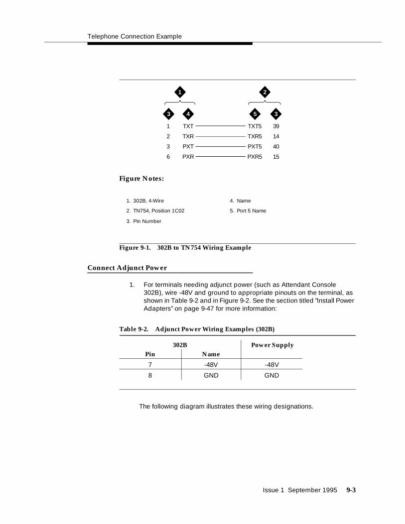
Telephone Connection Example
Issue 1 September 1995 9-3
Figure Notes:
Figure 9-1. 302B to TN754 Wiring Example
Connect Adjunct Power
1. For terminals needing adjunct power (such as Attendant Console 302B), wire -48V and ground to appropriate pinouts on the terminal, as shown in Table 9-2 and in Figure 9-2. See the section titled "Install Power Adapters" on page 9-47 for more information:
The following diagram illustrates these wiring designations.
Table 9-2. Adjunct Power Wiring Examples (302B)
302B Power SupplyPin Name
7 -48V -48V
8 GND GND
1
2
3
6
TXT
TXR
PXT
PXR
TXT5
TXR5
PXT5
PXR5
39
14
40
15
3 34 5
1 2
1. 302B, 4-Wire
2. TN754, Position 1C02
3. Pin Number
4. Name
5. Port 5 Name

Install and Wire Telephones and Other Equipment
9-4 Issue 1 September 1995
Figure Notes:
Figure 9-2. Adjunct Power Wiring Example (302B)
2. The 400B2 adapter is convenient for connecting local power to a modular plug. See Figure 9-3.
Figure 9-3. 400B2 Adapter Connecting to a Modular Plug
7
8
-48
GND
-48
GND
3 4
1
2
1. 302B
2. Pin Number
3. Name
4. Power Supply
4 6
5
3
2
1
1. Flush mounted information outlet
2. Surface mounted information outlet
3. To individual power unit
4. 400B2 Adapter
5. To telephone
6. Destination Service Access Point (DSAP) power cord
Figure Notes:

Analog Station or 2-Wire Digital Station Example
Issue 1 September 1995 9-5
Adjunct power can be provided from the equipment room or equipment closet with 1145B1 power unit. See "Install the 1145B1 Power Supply" on page 9-26 for more information.
Each DEFINITY System port network can provide power for up to three attendant consoles. This source of power is preferred for the attendant consoles because it has the same battery backup as the system. See the Auxiliary Power pinout information in Table 9-6 on page 9-11.
Adjunct power can be provided locally at the telephone or console by the MSP-1 Power Supply. See "Install the MSP-1 Power Supply" on page 9-34.
Analog Station or 2-Wire Digital Station Example
Steps 1-3 of each example should have been completed in the Provisioning Plan found in Chapter 2, "Plan and Prepare the Site", step 8.
This example is typical of the 2-wire digital stations (603E, 84xx, 94xx, 302B), 2-wire analog stations (500, 2500, 71xx), analog Central Office (CO) trunks, direct inward dialed (DID) trunks, and external alarms.
1. Choose a peripheral to connect (such as analog station or 2-wire digital station).
2. Choose the port circuit pack to use and its carrier and slot number (from Table 9-7 on page 9-13). (e.g., TN2183 analog line, Cabinet 1, Carrier C, Slot 1).
3. Choose a port circuit on the port circuit pack, for example Port 3.
4. Install cross-connect jumpers to connect the named pinouts from the analog station or 2-wire digital station to the like-named pinouts on the port circuit pack. This pinout information is taken from Table 9-9 for the analog station and Table 9-8 to Table 9-9 for the TN2183 circuit pack.
5. Administer on the G3 Management Terminal (G3MT). See the DEFINITY G3 Implementation Guide for more details.
The wiring designations for this example are listed in Table 9-4, and are illustrated in Figure 9-4.

Install and Wire Telephones and Other Equipment
9-6 Issue 1 September 1995
The following diagram illustrates these wiring designations.
Figure Notes:
Figure 9-4. Analog Station 2500 to TN2183 Analog Line Wiring Example
Analog Tie Trunk Example
Steps 1-3 of each example should have been completed in the Provisioning Plan in Chapter 2, "Plan and Prepare the Site", Step 8.
This example shows how to connect analog tie trunk wiring from one DEFINITY System Generic 3 to another DEFINITY System Generic 3:
1. Choose a peripheral to connect (such as Tie Trunk).
2. Choose the port circuit pack to use and its carrier and slot number. (such as TN760, Cabinet 1, Carrier C, Slot 05).
Table 9-3. Wiring Example of Analog Station 2500 to TN2183Analog Line
Analog Station 2500TN2183 Analog Line,
Position 1C01Pin (2-pair modular) Name Port 3 Name Pin
2 T T3 28
3 R R3 03
2
3
T
R
T3
R3
28
03
3 34 5
1 2
1. Analog Station 2500
2. TN2183 Analog Line, position 1C01
3. Pin Number
4. Name
5. Port 3 Name

Analog Tie Trunk Example
Issue 1 September 1995 9-7
3. Choose a port circuit on the port circuit pack (such as Port 02).
4. Set option switches on the port board (TN760 tie trunk) as described in Appendix H, "Option Switch Settings".
5. Install cross-connect jumpers to connect the named pinouts from the tie trunk circuit pack to the appropriate leads on the external Tie Trunk. Names of the Tie Trunk leads must be determined from the manufacturer or supplier of the external trunk circuit. The example in Figure 9-5 and Table 9-4 shows a DEFINITY System Tie trunk connected to a DEFINITY System tie trunk. For tie trunk TN760, refer to Table 9-8 and Table 9-9.
6. Administer on the Trunk Group Screen of the terminal. See the DEFINITY G3 Implementation Guide for more details.
The wiring designations for this example are listed in Table 9-4 and are illustrated in Figure 9-5.
The following diagram illustrates these wiring designations.
Table 9-4. Analog Tie Trunk Wiring Designations (TN760)
External Trunk or Adapter TN760, Position 1C05Pin Port 1 Name Port 2 Name Pin
26 T1 T12 30
1 R1 R12 5
27 T11 T2 29
2 R11 R2 4
28 E1 M2 6
3 M1 E2 31

Install and Wire Telephones and Other Equipment
9-8 Issue 1 September 1995
Figure Notes:
Figure 9-5. Analog Tie Trunk Wiring Example (TN760)
In Figure 9-5, the following abbreviations apply:
T,R Private Branch Exchange (PBX) voice transmit
T1,R1 Private Branch Exchange (PBX) voice receive
M Private Branch Exchange (PBX) signal send
E Private Branch Exchange (PBX) signal receive
T2
R2
T12
R12
E2
M2
T1
R1
T11
R11
E1
M1
29
4
30
5
31
6
26
1
27
2
28
3
3 34 4
1 2
1. External Trunk or Adapter
2. TN760, Position 1C05
3. Pin Number
4. Port 2 Name

Digital Tie Trunk Example
Issue 1 September 1995 9-9
Digital Tie Trunk Example
Steps 1-3 of each example should have been completed in the Provisioning Plan in Chapter 2, "Plan and Prepare the Site", Step 8.
This example shows how to connect digital tie trunk wiring from one DEFINITY System Generic 3 to another DEFINITY System Generic 3:
1. Choose a peripheral to connect (such as DS1/E1)
2. Choose the port board to use and its carrier and slot number (such as TN464, Cabinet 1, Carrier C, Slot 06).
3. Choose a port circuit on the port board (such as Port 03).
4. Install cross-connect jumpers to connect the named pinouts from the Digital Trunk circuit pack to like-named pinouts on the manufacturer’s or supplier’s external digital trunk as shown in the following example. This pinout information is taken from Table 9-8 on page 9-16 and Table 9-9 on page 9-17.
5. Set option switches on the port circuit pack (TN464 digital trunk) according to Appendix H, "Option Switch Settings".
6. Administer on the Digital Service Level 1 (DS1) and Trunk Group Screens of the G3 Management Terminal. See the DEFINITY G3 Implementation Guide for more details.
The wiring designations for this example are listed in Table 9-5, and are illustrated in Figure 9-6.
LI* Balanced Input Pair.
LO* Balanced Output Pair.
The following diagram illustrates these wiring designations.
Table 9-5. Digital Tie Trunk Wiring Designations (TN464)
External Trunk Circuit Name TN464, Position 1C06
Name Pin Number
LI (Line In) LO (Line Out) 48
LI* (Line In) LO* (Line Out) 23
LO* (Line Out) LI* (Line In) 47
LO (Line Out) LI (Line In) 22

Install and Wire Telephones and Other Equipment
9-10 Issue 1 September 1995
Figure Notes:
Figure 9-6. TN464 Wiring Example
Auxiliary Connector Outputs
The control carrier outputs cable pinouts are shown in Table 9-6 on page 9-11. The control carrier AUX connector outputs include the following:
■ Alarm monitoring for the auxiliary cabinet
■ Seven -48VDC power sources for emergency transfer units
■ Three -48VDC power sources for remotely powering three attendant consoles or telephone adjuncts.
■ The INADS (remote system management terminal interface) trunk connection location.
■ Access to a relay contact is available to actuate a light, bell, or similar type customer-provided alarm device. The relay can be administered to make contact when a major, minor or warning alarm condition occurs in the switch. The circuitry required for this feature must be provided by the customer. The device connected to the alarm leads must not exceed a rating of 100 volts at 3/4 amps. The pinouts for an external alarm are shown in Table 9-6 on page 9-11.
A connector labeled AUX is provided on the back of the control carrier. Connect a 25-pair cable from this connector to a connecting block of the trunk/auxiliary field designated by callout 2 in Figure 5-1 on page 5-2.
LO
LO*
LI
LI*
LO
LO *
LI
LI*
48
23
22
47
3 3 4
1 2
1. External Trunk
2. TN464, Position 1C06
3. Name
4. Pin Number
■ LI* Balanced Input Pair
■ LO* Balanced Output Pair

Auxiliary Connector Outputs
Issue 1 September 1995 9-11
Table 9-6. Auxiliary Lead Appearances at AUX Connector on Cabinet Back
Single-CarrierAuxiliary Connection
Outputs
808A 574-5
Emergency Power
Pin Transfer UnitTransfer
Unit
Color 1,2 Number Outputs Outputs
W-BL
BL-W
26
1
Major* TC TC
W-O
O-W
27
2
Minor* TK TK
W-G
G-W
28
3 GRDLC LC
W-BR
BR-W
29
4 GRDST ST
W-S
S-W
30
5 GRDTC TC
R-BL
BL-R
31
6 GRDTK TK
R-O
O-R
32
7 GRDLC LC
R-G
G-R
33
8
Not Connected ST ST
R-BR
BR-R
34
9
Not Connected TC TC
R-S
S-R
35
10
Not Connected TK TK
BK-BL
BL-BK
36
11
-48
GND
Emergency
Transfer
Relay
Power
Ø
LC LC
BK-O
O-BK
37
12
-48
GND
ST ST
BK-G
G-BK
38
13
-48
GND
TC TC
BK-BR
BR-BK
39
14
-48
GND
TK TK
BK-S
S-BK
40
15
-48
GND
LC LC
Y-BL
BL-Y
41
16
-48
GND
ST ST
Y-O
O-Y
42
17
-48
GND
TC TC

Install and Wire Telephones and Other Equipment
9-12 Issue 1 September 1995
* External alarm, with signal incoming to switch.** External alarm, with signal outgoing from switch.1 Color designation is AA-BB, where AA is the main wire color, and BB is the color of the short
stripe on the wire.2 For translation purposes, the following wire colors apply in the above table:
W WhiteBL BlueO OrangeG GreenBR BrownS Slate (Grey)R RedBK BlackY YellowV Violet
Y-G
G-Y
43
18
Not Connected TK TK
Y-BR
BR-Y
44
19
GND
-48
Aux Power
Ø
LC LC
Y-S
S-Y
45
20
GND
-48
ST ST
V-BL
BL-V
46
21
GND
-48
COM1
NO1
COM1
N01
V-O
O-V
47
22
Not Connected NC2
NC1
NC2
NC1
V-G
G-V
48
23
Ext Alarm A**
Ext Alarm Return
COM2
N02
C0M2
N02
V-BR
BR-V
49
24
Not Connected
V-S
S-V
50
25
INADS Tip
INADS Ring
GRD
-48V
GRD
-48V
Table 9-6. Auxiliary Lead Appearances at AUX Connector on Cabinet Back
Single-CarrierAuxiliary Connection
Outputs
808A 574-5
Emergency Power
Pin Transfer UnitTransfer
Unit
Color 1,2 Number Outputs Outputs

Auxiliary Connector Outputs
Issue 1 September 1995 9-13
Table 9-7. Port Board and Telephone Pin Designations
Pin on Modular plug
4-wire;302B, 8403, 8410, 8434, 603E, 9403, 9434
2-wire;302B, 8403, 8410, 8434, 603E, 9403, 9410, 9434
8510T Basic Rate Interface (BRI) (with adjunct speaker phone)
Analog Station, Modem NT1
Z3A1 & Z3A2 Asynchronous Data Units (ADU), Processor Data Module (PDM)
1 TXT TXT
2 TXR T TXR
3 PXT TXT R PXT
4 T PXR T
5 R PXT No
Connection
(4-pin
modular
jack)
R
6 PXR TXR PXR
7 -48VDC (-48VDC) (-48VDC) -48VDC
8 GRD GRD GRD GRD
Circuit Pack
TN754 4-wire digital
TN2181 2-wire digital
TN556, integrated services digital network basic rate interface line
TN2183 Analog line
TN2198 2-wire basic rate interface line TN726 Data Line
PX private branch exchange transmit T Tip (A)TX Terminal transmit R Ring (B)

Install and Wire Telephones and Other Equipment
9-14 Issue 1 September 1995
Figure 9-7. Connections for Attendant Console
TXT
TXR
PXT
PXR
11
13 13
12
109
8
76
5
432
1
P+
P-
P+
P-
P+
P-
1. Station Wiring
2. Attendant Console
3. Information Outlet
4. Satellite site, or adapter location
5. Part or cross-connect field
6. Station side
7. Switch side
8. Blue or white field
9. 100P6A patch cord or jumpers
10. Purple field
11. TN754 circuit pack port
12. 4-pair line cord
13. -48 VDC power source
Figure Notes:

APP Connector and Cable Diagrams (Pinout Charts)
Issue 1 September 1995 9-15
Figure Notes:
1. Cable connection
Figure 9-8. 302B1 Attendant Console
APP Connector and Cable Diagrams (Pinout Charts)
See Table 9-9 for lead designations. The circuit packs and auxiliary equipment are classified as follows:
1
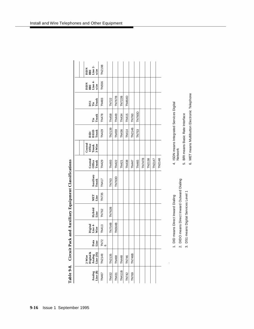
Install and Wire Telephones and Other Equipment
9-16 Issue 1 September 1995
Tab
le 9
-8.
Cir
cuit
Pac
k a
nd
Au
xili
ary
Eq
uip
men
t C
lass
ific
atio
ns
.
An
alog
Lin
e (8
)
2-W
ire
Dig
ital
&
An
alog
Lin
e (1
6)D
ata
Lin
e
Dig
ital
Lin
e 4-
Wir
eH
ybri
dL
ine
ME
TL
ine
Au
xili
ary
Tru
nk
Cen
tral
O
ffic
eT
run
k
DID
/D
IOD
Tru
nk
Tie
Tru
nk
DS
1T
ieT
run
k
ISD
NB
RI
Lin
e 4-
wir
e
Cen
tral
Off
ice
Tru
nk
3-W
ire
ISD
NB
RI
Lin
e 2-
wir
e
TN46
7TN
2149
TN72
6TN
413
TN7
62TN
735
TN
417
TN
429
TN42
9T
N47
8TN
483
TN55
6TN
2198
TN43
2TN
2135
TN75
4BTN
762
BT
N76
3T
N49
3TN
2139
TN
458
TN72
2
TN43
1TN
468
TN56
4BT
N76
3DT
N42
2TN
459
TN
449
TN76
7B
TN41
1B
TN44
8T
N42
1TN
436
TN
434
TN72
2B
TN74
2TN
746
TN
438
TN41
4T
N41
5TN
464
D
TN76
9TN
746B
TN
447
TN21
46T
N76
0
TN
465
TN75
3T
N76
0D
TN
747B
TN
2138
TN
2147
TN
2148
1.D
ID m
eans
Dire
ct In
war
d D
ialin
g
2.D
IDO
mea
ns D
irect
Inw
ard
Out
war
d D
ialin
g
3.D
S1
mea
ns D
igita
l Ser
vice
s Le
vel 1
4.IS
DN
mea
ns In
teg
rate
d S
ervi
ces
Dig
ital
Net
wor
k
5.B
RI m
eans
Bas
ic R
ate
Inte
rfac
e
6.M
ET
mea
ns M
ultib
utto
n E
lect
roni
c Te
lep
hone

Issue 1 September 1995 9-17
Tab
le 9
-9.
Cir
cuit
Pac
k a
nd
Au
xili
ary
Eq
uip
men
t L
ead
s (P
inou
t C
har
ts)
Col
or 1,
2
Con
n.
Pin
Nu
mb
ers
An
alog
Lin
e8
por
ts
2-W
ire
Dig
ital
Lin
e an
dA
nal
ogL
ine
16 p
orts
Dat
aL
ine
Dig
ital
Lin
e4-
wir
eH
ybri
dL
ine
ME
TL
ine
AU
XT
rk.
CO
Trk
.
CO
Trk
.3-
wir
e
DID
/D
IOD
Trk
.T
ieT
rk.
DS
1T
ieT
rk.
ISD
NB
RI
Lin
e4-
wir
e
ISD
NB
RI
Lin
e2-
wir
e
W-B
L26
T1T1
V1T
1T1
T1T1
A1
T1
T1P
XR1
T1
BL-
W01
R1
R1
V1R
1R
1R
1R
1B
1R
1R
1P
XT1
R1
W-O
27T2
TXT1
TXT1
CT
1TX
T1S
Z1T1
1TX
T1T2
O-W
02R
2TX
R1
TXR
1C
R1
TXR
1S
Z11
R1
1TX
R1
R2
W-G
28T3
PX
T1P
XT1
P-1
PXT
1S
1E
1P
XR2
T3
G-W
03R
3P
XR
1P
XR
1P
+1
PXR
1S
11C
1M
1P
XT2
R3
W-B
R29
T2T4
V1T
2T2
T2T2
A2
T2
T2TX
T2T4
BR
-W04
R2
R4
V1R
2R
2R
2R
2B
2R
2R
2TX
R2
R4
W-S
30TX
T2TX
T2C
T2
TXT2
SZ2
T12
PXR
3T5
S-W
05TX
R2
TXR
2C
R2
TXR
2S
Z12
R1
2P
XT3
R5
R-B
L31
PX
T2P
XT2
P-2
PXT
2S
2E
2TX
T3T6
BL-
R06
PX
R2
PX
R2
P+
2PX
R2
S12
C2
M2
TXR
3R
6
R-O
32T3
V1T
3T3
T3T3
A3
T3
T3P
XR4
T7
O-R
07R
3V
1R3
R3
R3
R3
B3
R3
R3
PX
T4R
7
R-G
33TX
T3TX
T3C
T3
TXT3
SZ3
T13
TXT4
T8
G-R
08TX
R3
TXR
3C
R3
TXR
3S
Z13
R1
3TX
R4
R8
R-B
R34
T5P
XT3
PX
T3P
-3PX
T3
S3
E3
PXR
5T9
BR
-R09
R5
PX
R3
PX
R3
P+
3PX
R3
S13
C3
M3
PX
T5R
9
R-S
35T4
T6V
1T4
T4T4
T4A
4T
4T4
TXT5
T10
S-R
10R
4R
6V
1R4
R4
R4
R4
B4
R4
R4
TXR
5R
10
BK
-BL
36T7
TXT4
TXT4
CT
4TX
T4S
Z4T1
4P
XR6
T11
Con
tinu
ed o
n ne
xt p
age
9

Install and Wire Telephones and Other Equipment
9-18 Issue 1 September 1995
BL-
BK
11R
7TX
R4
TXR
4C
R4
TXR
4S
Z14
R1
4P
XT6
R11
BK
-O37
T8P
XT4
PX
T4P
-4PX
T4
S4
E4
TXT6
T12
O-B
K12
R8
PX
R4
PX
R4
P+
4PX
R4
S14
M4
TXR
6R
12
BK
-G38
T5T9
V1T
5T5
T5
PXR
7
G-B
K13
R5
R9
V1R
5R
5R
5P
XT7
BK
-BR
39T1
0TX
T5TX
T5C
T4
TXT7
BR
-BK
14R
10TX
R5
TXR
5C
R4
TXR
7
BK
-S40
T11
PX
T5P
XT5
P-5
PXR
8
S-B
K15
R11
PX
R5
PX
R5
P+
5P
XT8
Y-B
L41
T6T1
2V
1T6
T6T
6TX
T8
BL-
Y16
R6
R12
V1R
6R
6R
6TX
R8
Y-O
42TX
T6TX
T6C
T6
PXR
9
O-Y
17TX
R6
TXR
6C
R6
PX
T9
Y-G
43P
XT6
PX
T6P
-6TX
T9
G-Y
18P
XR
6P
XR
6P
+6
TXR
9
Y-B
R44
T7V
1T7
T7T
7P
XR10
BR
-Y19
R7
V1R
7R
7R
7P
XT1
0
Y-S
45TX
T7TX
T7C
T7
TXT1
0
S-Y
20TX
R7
TXR
7C
R7
TXR
10
V-B
L46
T13
PX
T7P
XT7
P-7
PXR
11
BL-
V21
R13
PX
R7
PX
R7
P+
7P
XT1
1
V-O
47T8
T14
V1T
8T8
T8
LI*
TXT1
1
O-V
22R
8R
14V
1R8
R8
R8
LITX
R11
Tab
le 9
-9.
Cir
cuit
Pac
k a
nd
Au
xili
ary
Eq
uip
men
t L
ead
s (P
inou
t C
har
ts)
— C
onti
nued
Col
or 1,
2
Con
n.
Pin
Nu
mb
ers
An
alog
Lin
e8
por
ts
2-W
ire
Dig
ital
Lin
e an
dA
nal
ogL
ine
16 p
orts
Dat
aL
ine
Dig
ital
Lin
e4-
wir
eH
ybri
dL
ine
ME
TL
ine
AU
XT
rk.
CO
Trk
.
CO
Trk
.3-
wir
e
DID
/D
IOD
Trk
.T
ieT
rk.
DS
1T
ieT
rk.
ISD
NB
RI
Lin
e4-
wir
e
ISD
NB
RI
Lin
e2-
wir
e
Con
tinu
ed o
n ne
xt p
age

Issue 1 September 1995 9-19
V-G
48T1
5TX
T8TX
T8C
T8
LOP
XR12
G-V
23R
15TX
R8
TXR
8C
R8
LO*
PX
T12
V-B
R49
T16
PX
T8P
XT8
P-8
LBA
CK
2TX
T12
BR
-V24
R16
PX
R8
PX
R8
P+
8LB
AC
K1
TXR
12
Tab
le 9
-9.
Cir
cuit
Pac
k a
nd
Au
xili
ary
Eq
uip
men
t L
ead
s (P
inou
t C
har
ts)
— C
onti
nued
Col
or 1,
2
Con
n.
Pin
Nu
mb
ers
An
alog
Lin
e8
por
ts
2-W
ire
Dig
ital
Lin
e an
dA
nal
ogL
ine
16 p
orts
Dat
aL
ine
Dig
ital
Lin
e4-
wir
eH
ybri
dL
ine
ME
TL
ine
AU
XT
rk.
CO
Trk
.
CO
Trk
.3-
wir
e
DID
/D
IOD
Trk
.T
ieT
rk.
DS
1T
ieT
rk.
ISD
NB
RI
Lin
e4-
wir
e
ISD
NB
RI
Lin
e2-
wir
e
Con
tinu
ed o
n ne
xt p
age

Install and Wire Telephones and Other Equipment
9-20 Issue 1 September 1995
Thi
s p
ag
e le
ft in
tent
iona
lly b
lank
so
you
can
rem
ove
the
pino
ut c
hart
from
the
bo
ok
if ne
cess
ary.
V-S
50
S-V
25
† Th
e w
ire
colo
rs in
this
pin
out c
hart
app
ly o
nly
to B
25A
and
A25
B c
able
s. H
600-
307,
60 c
able
col
ors
are
not s
how
n.
With
in th
is c
hart
, the
follo
win
g a
bbre
viat
ions
app
ly fo
r ana
log
tie tr
unks
:
T,R
PB
X tr
ansm
it vo
ice
T1,
R1
PB
X r
ecei
ve v
oice
MP
BX
tran
smit
sign
al
EP
BX
rec
eive
sig
nal
PXP
BX
tran
smit
TT
ip(A
)G
reen
TXT
erm
inal
tran
smit
RR
ing
(B)
Red
SSl
eeve
LI, L
I*D
igita
l Tru
nk
INLO
, LO
*D
igita
l Tru
nk
OU
T
1C
olo
r de
sig
natio
n is
AA
-BB
, whe
re A
A is
the
mai
n w
ire c
olor
, an
d B
B is
the
colo
r of
the
shor
t
stri
pe o
n th
e w
ire.
2F
or tr
ansl
atio
n pu
rpos
es, t
he fo
llow
ing
wire
col
ors
appl
y in
the
abov
e ta
ble:
WW
hite
BL
Blu
e
OO
rang
e
GG
reen
BRB
row
n
SS
late
(Gre
y)
RR
ed
BK
Bla
ck
YY
ello
w
VV
iole
t
Tab
le 9
-9.
Cir
cuit
Pac
k a
nd
Au
xili
ary
Eq
uip
men
t L
ead
s (P
inou
t C
har
ts)
— C
onti
nued
Col
or 1,
2
Con
n.
Pin
Nu
mb
ers
An
alog
Lin
e8
por
ts
2-W
ire
Dig
ital
Lin
e an
dA
nal
ogL
ine
16 p
orts
Dat
aL
ine
Dig
ital
Lin
e4-
wir
eH
ybri
dL
ine
ME
TL
ine
AU
XT
rk.
CO
Trk
.
CO
Trk
.3-
wir
e
DID
/D
IOD
Trk
.T
ieT
rk.
DS
1T
ieT
rk.
ISD
NB
RI
Lin
e4-
wir
e
ISD
NB
RI
Lin
e2-
wir
e
Con
tinu
ed o
n ne
xt p
age

Install Initialization and Administration System (INADS) Interface
Issue 1 September 1995 9-21
Install Initialization and Administration System (INADS)Interface
The Initialization and Administration System (INADS) provides a 1200 Bits Per Second (bps) modem connection for the remote management terminal for DEFINITY System Generic 3.
Figure 9-9 shows a typical Initialization and Administration System (INADS) installation, where the analog port is connected from the switch directly to the connectors on the auxiliary cable pins.
Figure 9-9. Analog Port Connection
As an alternative, Figure 9-10 illustrates a switched connection to the Initialization and Administration System (INADS) interface.
1
2 3
4
G3
TR
1. Initialization and Administration System (INADS) interface on AUX connector (see Table 9-6 on page 9-10)
2. Auxiliary cable
3. External analog Central Office (CO) trunk
4. Cross-connect field
Figure Notes:
9

9-22 Issue 1 September 1995
Figure 9-10. Initialization and Administration System (INADS) Installation for Digital Trunk Access
1
2
3
4
5
6
7
G3
8
9
TR
TR
1. Digital Central Office (CO) trunk (TN464)
2. Analog line (TN2183)
3. Initialization and Administration System (INADS) Interface (T,R)
4. Analog extension (T,R)
5. Auxiliary cable
6. Pin 26-50 (refer to pinout chart)
7. Cross-connect field
8. Processor (TN786)
9. External digital Central Office (CO) trunk
Figure Notes:

Install Emergency Transfer Units and Associated Telephones
Issue 1 September 1995 9-23
Install Emergency Transfer Units andAssociated Telephones
Emergency transfer capability is provided by a transfer unit mounted on the wall next to the trunk/auxiliary cross-connect field.
Analog telephones can be used for emergency transfer. The 500-and 2500-type telephones can also be used as normal extensions. Emergency transfer capability may be provided on Central Office (CO) trunks.
The following transfer units are available:
■ The 808A Emergency Transfer Panel provides emergency trunk bypass or power-fail transfer for up to five incoming analog Central Office (CO) trunk loops to five selected private branch exchange analog single line telephones. When a power failure or other system problem interrupts service, the sets are automatically and directly connected to the Central Office trunks and are available for emergency use outside the private branch exchange service environment.
When a telephone connected to the 808A goes off-hook during bypass, circuitry inside the panel places signalling on the Central Office (CO) trunk causing the Central Office (CO) to return dial tone. Each 808A bypass circuit can be switched to either loop start or ground start signalling.
■ The 574-5 power transfer unit serves up to five power failure transfer telephones. The unit provides automatic ground start.
At the cross-connect field, the transfer units are connected to a yellow terminal row/connecting block in the trunk/auxiliary field. The units are powered (-48VDC) from the EM TRANS RELAY PWR terminals. Refer to Figure 9-6 for pinout information. There are seven EM TRANS RELAY PWR terminal pairs to provide power to up to seven transfer units.
Install the 808A Emergency Transfer Panel
The 808A is connected to the cross-connect field through a B25A or A25B cable. Install the 808A Emergency Transfer Panel according to the instructions packed with the unit.

9-24 Issue 1 September 1995
Install External Ringing
Requirements
Figure 9-11 on page 9-25 shows the connections for external ringing provided by a device, such as a gong, chime, or bell, connected to an information outlet. The switch side of the cross-connect field is connected to an analog line circuit pack (such as a TN2183) located in a port carrier. A maximum of three devices can be connected to one TN2183 circuit pack port.
Installation
Install ringing device as follows:
1. Determine port assignment of “External Alert Port (trunk answer any station)” feature from Console Parameters Form:
2. Install patch cord/jumper wires at cross-connect field.
3. Mount the ringing device at the location specified in the Provisioning Plan. Refer to "Plan and Prepare the Site" on page 1-3.
4. Connect a 2-pair line cord (modular plug at one end) from the information outlet to the ringing device (Figure 9-3).
5. Connect red (R) and green (T) leads to the ringing device.
6. Administer according to the instructions found in the U.S. English book, DEFINITY Communications System Generic 3 Implementation, 555-230-655.
EXAMPLE: Port Number 2 B 02 01
Cabinet Carrier Slot Circuit

Install Queue Warning Indicator
Issue 1 September 1995 9-25
Figure 9-11. Connections for External Ringing or Queue Warning Indicator
Install Queue Warning Indicator
Requirements
Figure 9-11 shows the connections for the queue warning indicator. An AC indicator (lamp) such as a 21C49 is optional for use as a queue warning indication in a Uniform Call Distribution (UCD)/Direct Departmental Calling (DDC) queue. The lamp is connected to an information outlet. The switch side of the cross-connect field is connected to an analog line circuit pack (such as a TN2183) located in a port carrier.
2 3
8
4
9
5
10
11
7
61
12
14
13 T
R
1. AC lamp or ringing device
2. Information outlet
3. Satellite site or adapter location
4. Station side
5. Switch side
6. Analog line port circuit pack (TN2183 or TN746B circuit pack)
7. Purple field
8. Patch cord or jumpers
9. Blue or white field
10. Station wiring
11. Line cord
12. Part of cross connect field
13. Red
14. Green
Figure Notes:

9-26 Issue 1 September 1995
Installation
Install queue warning indicator as follows:
1. Determine port assignment for queue warning indicator from Hunt Group Form:
2. Install patch cord/jumper wires at cross-connect field.
3. Mount indicator at specified location.
4. Connect a 2-pair line cord (modular plug at one end) from the information outlet to the indicator. See Figure 9-3.
5. Connect red (R) and green (T) leads to the indicator.
6. Administer per DEFINITY Communications System Generic 3 V2 Implementation, 555-230-655.
Install the 1145B1 Power Supply
The 1145B1 closet power arrangement provides an uninterruptible -48VDC power source with battery and 1145B1 distribution unit for Integrated Services Digital Network (ISDN)/digital communications protocol terminal equipment, terminal adjuncts, and other customer provided equipment. During AC power interruptions, batteries automatically provide continuous power to the load.
During normal operation, the power supply/charger provides DC power to the load via the distribution unit while maintaining the battery in a fully charged condition. A manual switch on the distribution unit allows the user to redirect reserve power to outputs 1 through 8 or 1 through 32, with the switch set to the 1 through 32 setting, all outputs will be provided battery reserve power.
The 1145B1/1146B1 is a -48V power supply with 200 watt total output. This unit is a 110-type distribution unit with 32 output circuits. Each output is current limited by a positive temperature coefficient thermistor (PTC). The thermistor limits the maximum output to 12 watts and prevents excessive current from causing hazards. If the thermistor is current limiting, there is a short across the power pair. Each 1145B1 output has an individual light emitting diode to indicate the status of the thermistor. If the light emitting diode is on, the thermistor has a short on that power pair.
Not all outputs can simultaneously provide 12 watts. The average power per output cannot exceed 6.25 watts (200/32 = 6.25). The 1145B1 is designed to power one integrated services digital network terminal or digital communications protocol adjunct per output. The maximum number of terminals or adjuncts is
EXAMPLE: Port Number 2 B 02 01
Cabinet Carrier Slot Circuit

Install the 1145B1 Power Supply
Issue 1 September 1995 9-27
32. The 1145B1 (not 1145A1) is required for installation outside the United States.
Auxiliary power (local or bulk) is always required in the following situations:
■ Attendant console 302B.
■ Any 8520 terminal.
■ Any 7500-series or 8500-series terminal with an asynchronous data module.
■ Any 7500-series terminal (whether in passive bus, or point to point, that is, one per basic rate interface port).
■ Any 8510 terminal in passive bus or with an asynchronous data module. (Provide auxiliary power to an 8510 unless you are certain it will never be used to support such applications as data or video.)
This section tells how to install the 1145B1 Power Supply, 1146B1 Power Distribution Unit, and 2.5 amp hour (AH) back-up batteries. All units are mounted on wall-mounting plates. The wall-mounting plates should be installed first. The rest of the hardware can be mounted in any desired order. The next illustration shows how the power supply and wall-mounting plates fit together.
Wall-Mounting Plates
Two wall mounting plates are provided for easy assembly and to provide correct spacing between units for cooling. The top plate is needed for mounting the back-up battery. The bottom plate is needed to mount the Power Supply and Distribution Units. The plates can also be used for rack mounting the hardware by means of standard rack-mounting brackets.
1. Locate one plate directly below the other one such that the AC power cord (6-1/2 feet or 2 meters) reaches the desired electrical outlet from a power supply mounted on the bottom plate. Both plates should be located so the raised letters are right side up.
NOTE:A maximum of four Power Supplies can be powered from one dedicated 110VAC, 20 amp (or 230VAC, 15A) feeder. Use only unswitched receptacles. In other words, receptacles not connected to a wall switch.
2. Secure the wall mounting plates to a standard 3/4 inch (2 cm) thick plywood mounting board. Each mounting plate comes with four #10x1/2-inch wood screws.

9-28 Issue 1 September 1995
Figure 9-12. 1145B1/1146B1 Mounting Arrangement
2
9
1-8
1-32
3
5
87
Output Power OnCharging BatteryOn Battery Reserve
1145A1 Power Unit4
6
1
1
10
1. Wall mounting plate
2. 2.5 Amp Hour Battery
3. Battery bracket
4. AC power cord
5. 1146B power distribution unit
6. Unswitched outlet 120 VAC, 20 Amp or 230 VAC, 15 Amp)
7. 1145B Power Supply
8. Power cable
9. Battery backup switch settings
10. Inset
■ Wall must be at least 3/4” (1.9 cm) wood
Figure Notes:

Install the 1145B1 Power Supply
Issue 1 September 1995 9-29
Mount the 1145B1 Power Supply
The 1145B1 Power Supply unit is snap-fitted onto the bottom wall mounting plate without tools.
1. Perform this step using a "place, rotate, then snap" motion. The holes used for 1145B1 Power Supply mounting are indicated on the wall-mounting plate. The preceding illustration shows a side view of the mounting arrangement.
To dismount the unit, push the bottom of the power unit toward the mounting plate while pressing the two snaps on the bottom. Rotate upward and lower the unit.
Figure 9-13. Side View of 1145B1 Power Supply Mounting
1
9
6
8
2
3
4
5
7
1. 3/4 inch (2 cm) Plywood
2. AC Receptacle
3. 1145B1 Power Unit
4. Frame Ground
5. 16 AWG Installer Wiring
6. Snap
7. To Approved Ground
8. Wall Mounting Plate
9. Power Cord Snap-in Clips
Figure Notes:

9-30 Issue 1 September 1995
2. An installer-provided insulated ground wire, 16 AWG or greater, is required to connect the Power Supply frame ground lug to an approved ground. The Power Supply frame ground screw is located next to the AC receptacle to the left of the unit. The ground screw and the AC receptacle are shown in the preceding illustration.
3. Mark the Unit Number and Connectivity information on the front label next to the light emitting diodes.
Mount the 1146B1 Power Distribution Unit
The Power Distribution Unit is mounted onto the bottom wall mounting plate with three screws.
1. Insert and securely tighten the two #8-32x1/2-inch shoulder screws (they have an unthreaded section at the top) into the top holes designated for 1146B1 Power Distribution Unit on the wall mounting plate. Mount the unit on these two shoulder screws, using the key holes on the back of the unit. Secure the unit by inserting the #8-32x1-inch screw through the bottom of the unit (just above the wire clips) into the wall mounting plate and tighten.
2. Select the desired battery back-up switch option. The switch is preset to 1-32 (down position) option to provide battery back-up to all outputs. The up position provides battery back-up to outputs 1-8 only.
3. Connect the Power Distribution Unit to the Power Supply with the power cable. Bend and connect the cable. Refer to the Power Supply’s right-hand label to locate the output power connection.
Battery Mounting/Wiring
The back-up battery is placed in the battery bracket mounted onto the top wall-mounting plate using the four #10-32x1/2-inch screws.
1. Insert (do not tighten) two #10-32x1/2-inch screws into the top designated battery bracket holes on the wall mounting plate.
2. Place the battery bracket on these two screws and tighten the screws.
3. Insert the remaining two #10-32x1/2-inch screws into the battery bracket bottom holes and tighten.
4. Place the battery in the bracket. The battery cord exits from the right of the bracket. Make sure the label on the battery is visible.
5. Plug the battery cord into the Power Supply’s right rear receptacle. The rear receptacle is indicated on the Power Supply’s right label.

Install the 1145B1 Power Supply
Issue 1 September 1995 9-31
Power Up and Test
Powering up and testing should be performed only after all the hardware is properly mounted. The following table describes the meaning of the Power Supply light emitting diodes when lit.
1. Connect the AC power cord to Power Supply and route the cord to an appropriate AC outlet using the clips provided on the unit.
NOTE:A maximum of four Power Supplies can be powered from one dedicated 110VAC, 20A feeder. Use only unswitched receptacles.
2. Plug the cord into the outlet. This powers up the Power Supply (no ON/OFF switch).
3. Check AC operation of the 1145B1 Power Supply by monitoring the light emitting diodes (LED):
PASS: Green and yellow light emitting diodes (LED) at front of the unit should be lit together. Green means the Power Supply is providing power. Yellow means the battery is being charged. After the battery reaches full charge (maximum of twenty hours), the yellow light emitting diode (LED) should go out.
FAIL : If either green or yellow light emitting diode (LED) is not lit after powering up, check the connections. Test the AC outlet. If power is available to the Power Unit and the AC power cord and connections are good, replace the power unit.
4. Disconnect the AC plug on the Power Supply, this activates the DC supply.
5. Check DC (battery back-up) operation of the 1145B1 Power Supply by monitoring the light emitting diodes (LED):
PASS: The red and green light emitting diodes (LED) should be lit together. Red means the Power Supply is on battery back-up.
FAIL : If either green or red light emitting diode (LED) is not lit after disconnecting AC power, check the connections. If the connections are good, replace the power unit or batteries.
6. Reconnect AC power to the Power Supply. The green and yellow light emitting diodes (LED) should light as described before.
Light Emitting Diode Colour Meaning
Green Power Supply is providing power
Yellow Battery is charging
Red Power Supply is on battery reserve

9-32 Issue 1 September 1995
Wire the 1146B1 Power Distribution Unit
It may be better to wire endpoints to the 1146B1 while power from the 1145B1 is on. This way, a red light emitting diode (LED) on the distribution unit lights if you connect its associated circuit to shorted building wiring or to a shorted terminal.
1. Install cross-connect jumpers to wire from the Distribution Unit (the label shows polarity) to Pins 7 and 8 of the appropriate information outlet. Route the wires through the clip provided on the unit. If a red light emitting diode (LED) is on, see the next section Reset light emitting diodes (LED) on Power Distribution Unit. The following illustration shows a typical connection.
2. Mark lead destination on the label next to each connector on the Distribution Unit. Also mark the Unit Number and Connectivity information on the label.
Figure 9-14. Typical Wiring to a Terminal
4
2
1
10
32
17
16
12
3
7
6
5
8
11
1
99
1. Alternating Current (AC)
2. Installer-provided ground wire
3. Circuits 1-32
4. Power supply kit
5. Battery
6. 1145B1 Power Supply
7. 1146B1 Distribution Unit
8. Private branch exchange Port Circuit
9. Tip and Ring
10. Pins 7 & 8
11. Cross-Connect
12. Integrated Services Digital Network (ISDN)/ Display System Protocol (DSP) Terminal
Figure Notes:

Install the 1145B1 Power Supply
Issue 1 September 1995 9-33
Reset Light Emitting Diodes (LED) on Power Distribution Unit
A lit red light emitting diode (LED) next to any of the 32 power output connectors on the Power Distribution Unit indicates a short circuit in the building wiring or the terminal equipment. To reset the light emitting diode (LED), perform the following:
1. Disconnect the terminal equipment from the wall jack.
2. If the light emitting diode (LED) goes off, the terminal equipment is faulty and must be replaced. If the light emitting diode (LED) is still lit, find and repair the short circuit in the building wiring.
3. Reconnect the terminal equipment to the wall jack and re-test terminal equipment operation.
! WARNING:Important Safety Instructions follow.
When operating this equipment, basic safety precautions must be followed to reduce the risk of fire, electric shock and personal injury, including the following:
■ Read and understand all instructions.
■ Do not attach the power supply cord to building surfaces.
■ For continued back-up protection and battery reliability, replace batteries every four years.
■ Follow all warnings and instructions marked on the products.
■ Clean products only with a dry rag.
■ Do not use this product near water.
■ For mounting security, follow all installation instructions when mounting product.
■ Openings on top and bottom of power unit are provided for ventilation. Do not block or cover these openings. Do not exceed recommended environmental temperatures.
■ Operate these products only from the type of power source indicated on the product labels.
■ The power unit is equipped with a three wire grounding type plug; a plug having a third (grounding) pin. This plug will only fit into a grounding type power outlet. This is a safety feature. If you are unable to insert the plug into the outlet, contact an electrician to replace the outlet. Do not defeat the safety purpose of the grounding type plug.
■ Do not allow anything to rest on or spill into the products.
■ To reduce risk of fire and electrical shock, do not overload power outlets.

9-34 Issue 1 September 1995
■ Never push objects of any kind through the power supply or distribution unit slots as they may touch dangerous voltage points or short out parts that could result in a risk of fire or electrical shock.
■ To reduce risk of electric shock, do not disassemble these products. Return them for repair when needed. Opening or removing covers may expose you to dangerous voltages or other risks. Incorrect reassembly can cause electric shock when the products are subsequently used.
■ Power down the power unit (see label on power unit on how to do this) and refer servicing under the following conditions:
— if liquid has been spilled into any of the products
— if any of the products have been exposed to water
— if any of the products do not operate normally
— if any of the products have been dropped or damaged
— if any of the products exhibits a change in performance.
■ Do not attempt to recharge batteries on your own. The batteries may leak corrosive electrolyte or explode. The 1145B1 power unit recharges the batteries safely.
■ Remove the batteries if the power unit will not be used for a long period of time (several months or more) since during this time the battery may leak.
■ Discard discharged batteries as soon as possible. Discharged batteries are more likely to leak.
■ Do not store batteries in high temperature areas. Batteries stored in a cold environment should be protected from condensation during storage and warming. Batteries should be stabilized at room temperature prior to use after cold storage. Do not install batteries if the manufacturing date on the label indicates that the batteries are more than six months old.
Install the MSP-1 Power Supply
Underwriter’s Laboratories (UL) Information
The MSP-1 Power Supply has been tested and found to comply with the Underwriters Laboratories (UL) Standard Underwriter’s Laboratories 1459, second edition. This standard requires that you be advised of certain safety instructions regarding the use of the power supply. These safety instructions follow the table of certifications.
Complies Underwriter’s Laboratories (UL) 1459
Certified Canadian Safety Association (CSA) 22.2
Approved IEC 950

Install the MSP-1 Power Supply
Issue 1 September 1995 9-35
Important Safety Instructions
The most careful attention has been devoted to safety standards in the manufacture of this power supply. Safety is a major factor in the design of every power supply. But, safety is your responsibility too.
Please read carefully the helpful tips listed below and on the next page. These suggestions will enable you to take full advantage of this product. Then, retain these tips for later use.
! CAUTION:When using this power supply, the following safety precautions should always be followed to reduce the risk of fire, electric shock, and injury to persons.
■ Read and understand all instructions.
■ Follow all warnings and instructions marked on this power supply.
■ This product can cause dangerous shock if immersed in water. To avoid the possibility of electrical shock, do not use near water.
■ To reduce the risk of electric shock, do not disassemble this product. There are no user serviceable parts inside.
■ This product should be operated only from the type of AC power source indicated on the label. If you are not sure of the type of AC power being provided, contact a qualified service person.
■ Do not allow anything to rest on the power cord. Do not locate this product where the cord will be abused by persons walking on it.
■ Do not overload wall outlets and extension cords, as this can result in the risk of line or electric shock.
■ Disconnect the cords on this product and refer servicing to qualified service personnel under the following conditions:
— When the power supply cord or plug is damaged or frayed.
— If liquid has been spilled into the product.
— If the product has been exposed to rain or water.
— If the product does not operate normally by following the operating instructions.
— If the product has been dropped or the housing has been damaged.
— If the product exhibits a distinct change in performance.

9-36 Issue 1 September 1995
Description of the MSP-1 Power Supply
The MSP-1 (WP92464L1) Power Supply can be used to supply local power to Attendant Console 302B, Integrated Services Digital Network (ISDN) -T 75xx, and 85xx series telephones connected to an AT&T DEFINITY Communications System and to telephones needing auxiliary power for their vacuum fluorescent display. The MSP-1 can also supply auxiliary power to adjunct equipment such as the S201A and CS201A speaker phones or a 500A Headset Adapter attached to any currently manufactured analog, digital communications protocol, or Integrated Services Digital Network (ISDN)-T telephone equipped with an Adjunct jack.
! CAUTION:The MSP-1 Power Supply can be used only with telecommunications equipment, indoors, and in a controlled environment.
The MSP-1 Power Supply has a single output of -48VDC, 0.4 amperes, and can operate from either a 120 VAC 60 Hz Power source (105 to 129 VAC) or a 230 VAC 50 Hz Power source (198 to 264 VAC). Input voltage selection is automatic; that is, the power supply adjusts itself for the type of input voltage. The output capacity is 19.2 watts.
Locate the MSP-1 Power Supply
You may set the MSP-1 power supply on a flat surface such as a desk. Adhesive fastener strips are packed with the MSP-1. These are used to mount it on a vertical surface such as a wall.
! CAUTION:Do not locate the MSP-1 within six inches of the floor. Experience has proven that the MSP-1 will not survive the hazards of locating it near the floor.
Mount the MSP-1 Power Supply
The double-sided adhesive fastener strip allows you to mount the power supply on a flat vertical surface, such as on the wall or on the side of the desk.
Use the following procedure to mount the power supply near the telephone.
1. Locate a clean flat vertical surface on which to mount the power supply.
2. Peel the paper backing from one of the adhesive strips.
3. Firmly press the strip to the mounting surface. The fastener side of the strip should be directed outward.
4. Peel the paper backing from the remaining adhesive strip.

Install the MSP-1 Power Supply
Issue 1 September 1995 9-37
5. Place the adhesive side on the top of the MSP-1 and press the strip down so it adheres to the surface. Do not place the strip on the bottom of the power supply where the rubber feet are located.
6. Carefully align the fastener surface on the top of the power supply with the fastener surface on the wall or desk and press the two surfaces together firmly.
Connect the Power Supply
One power supply will support one telephone with or without an adjunct.
The maximum loop range between the telephone and the power supply is 250 feet (76 meters).
The power output is provided through 3 modular jacks on the power supply. These jacks are labelled as shown:
The PHONE and LINE jacks are 8-pin female non-keyed 657-type jacks that can accept D4, D6, and D8 modular plug cables. The OTHER jack is a 6-pin female non-keyed 657-type jack.
The powering arrangements shown in the following figures can be used with the MSP-1 Power Supply.
■ Figure 9-15 shows the local powering arrangement for Integrated Services Digital Network (ISDN) telephones, the Digital Communications Protocol (DCP) 7444 telephone voice frequency (VF) display, 84xx telephones, and adjuncts connected to all telephones except the 8102.
■ Figure 9-16 shows the local powering arrangement for adjuncts connected to the 8102 telephone.
The type of cord(s) needed to make these connections are designated in each figure.
PHONE OTHER LINE
-7 +8 -2 +5
The - and + numbers refer to the pins on which power is present and the polarity of that power.

9-38 Issue 1 September 1995
Figure 9-15. MSP-1 Connections for -48V Powered Telephones and their Adjuncts (Except the 8102)
3
8
4
9
5
10
1
6
2
7
1. MSP-1 Power supply
2. D8W cord
3. D4BU cord (For analog telephones) or D8W cord (For Digital Communications Protocol (DCP) and Integrated Services Digital Network (ISDN-T) telephones)
4. Wall jack
5. Adjunct jack
6. Line jack
7. Bottom of Voice Terminal/Telephone (7444 Shown)
8. “PHONE” Jack
9. “OTHER” Jack
10. “LINE” Jack
Figure Notes:

Install the Basic Rate Interface (BRI) Terminating Resistor
Issue 1 September 1995 9-39
Figure 9-16. MSP-1 Connections for Adjuncts Connected to the 8102 Analog Telephone
Install the Basic Rate Interface (BRI) Terminating Resistor
A terminating resistor is always required when the Basic Rate Interface (BRI) T-type interface card (TN556 circuit pack) is used (see #5ESS Switch Integrated Services Digital Network Customer Premises Planning Guide Issue 7, 533-700-100.
3
8
4
9
5
10
1
6
2
7
11
1. MSP-1 Power Supply
2. D4BU Cord
3. Adjunct jack (on rear of telephone)
4. Power Jack
5. Line Jack
6. D4BU Cord or 2-Wire Cord
7. Wall Jack
8. Bottom of 8102 Telephone
9. “PHONE Jack
10. “OTHER” JAck
11. “LINE” Jack
Figure Notes:

9-40 Issue 1 September 1995
The resistors balance the cable plant between the receiver and the transmitter on the T-type interface. The resistor is built into the NT1 and can be one of three values, depending on the configuration and the distance from the NT1 to the Integrated Services Digital Network (ISDN) terminal. The resistor value is controlled from the NT1. In some cases, a terminating resistor (TR) adapter is needed and can be placed in the satellite closet or work location.
NOTE:The 440A4 terminating resistor and 110RA1-12 terminating resistor block are Underwriters Laboratories (UL) listed. Most new installations will be of the 110RA1-12 terminating resistor block. The following installation instructions should be observed and heeded when installing a terminating resistor (TR) or any telephone equipment.
■ Never install telephone wiring during a lightning storm.
■ Never install telephone jacks in wet locations unless the jack is specifically designed for wet locations.
■ Never touch uninsulated wires or terminals unless the telephone line has been disconnected at the network interface.
■ Use caution when installing or modifying telephone lines.
Terminating Resistor Adapter
Figure 9-17 shows an 8-pin 440A4 terminating resistor (TR) adapter. The adapter is three inches long with plugs at both ends and a short cord to connect the 8-conductor jack. When is connected, a small screwdriver is needed for removal.
1
2
3
4
5
6
7
8
1
2
3
4
5
6
7
8
3
41
2
RR CC

Install the Basic Rate Interface (BRI) Terminating Resistor
Issue 1 September 1995 9-41
Figure 9-17. 8-Pin Terminating Resistor Adapter (440A4)
Closet Mounted (110RA1-12)
The 110RA1-12 terminating resistor block is designed to mount in the telecommunications wire closet. It consists of 12 (2-pair) circuits and provides the 100 Ohm termination used for Integrated Services Digital Network (ISDN) Basic Rate Interface (BRI) circuits. Figure 9-18 shows the wiring of the 110RA1-12. Three rows of 110D-4 connector blocks are mounted on a printed wire board along with circuit resistors and capacitors. The bottom row is designated as the input row and the top and middle rows are designated as the output rows. The circuit assembly is mounted on a standard 110A-100 pair mounting base. The 110RA1-12 is shipped with preprinted designation strips to simplify circuit identification and installation.
1. 8-Wide Plug
2. Cord
3. Plastic Housing
4. 8-Wide Jack
3
8
4
5
1
6
2
7
1 452 463 474 48

9-42 Issue 1 September 1995
Figure 9-18. Terminating Resistor Block (110RA1-12)
Figure 9-19 shows the wiring connections for the 110RA1-12 terminal block. The TN556 Basic Rate Interface (BRI) switch port is terminated to the bottom row C.
For point-to-point applications, the top row is connected to the blue station field. Notice the pair connects from the 110RA1-12 to the standard 4-pair circuit. Pair 1 from the 110RA1-12 is connected to Pair 1 of the station field, and Pair 2 is connected to Pair 3 of the station field.
1. Circuit 1
2. Circuit 2
3. Output row “A”
4. Output row “B”
5. Input row “C”
6. Only first circuit shown to all 12 circuits (2APR) per block
7. 110D-4 connector block
8. Printed circuit board mounted on standard 110A, 100APR block
Figure Notes:
1
2
11T R T1 R1
12
6
7
8
9
10
3
4
5
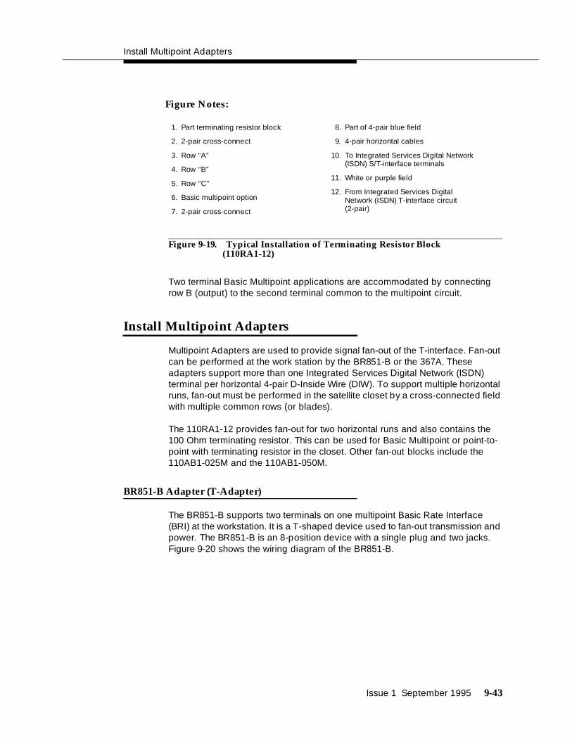
Install Multipoint Adapters
Issue 1 September 1995 9-43
Figure 9-19. Typical Installation of Terminating Resistor Block (110RA1-12)
Two terminal Basic Multipoint applications are accommodated by connecting row B (output) to the second terminal common to the multipoint circuit.
Install Multipoint Adapters
Multipoint Adapters are used to provide signal fan-out of the T-interface. Fan-out can be performed at the work station by the BR851-B or the 367A. These adapters support more than one Integrated Services Digital Network (ISDN) terminal per horizontal 4-pair D-Inside Wire (DIW). To support multiple horizontal runs, fan-out must be performed in the satellite closet by a cross-connected field with multiple common rows (or blades).
The 110RA1-12 provides fan-out for two horizontal runs and also contains the 100 Ohm terminating resistor. This can be used for Basic Multipoint or point-to-point with terminating resistor in the closet. Other fan-out blocks include the 110AB1-025M and the 110AB1-050M.
BR851-B Adapter (T-Adapter)
The BR851-B supports two terminals on one multipoint Basic Rate Interface (BRI) at the workstation. It is a T-shaped device used to fan-out transmission and power. The BR851-B is an 8-position device with a single plug and two jacks. Figure 9-20 shows the wiring diagram of the BR851-B.
1. Part terminating resistor block
2. 2-pair cross-connect
3. Row “A”
4. Row “B”
5. Row “C”
6. Basic multipoint option
7. 2-pair cross-connect
8. Part of 4-pair blue field
9. 4-pair horizontal cables
10. To Integrated Services Digital Network (ISDN) S/T-interface terminals
11. White or purple field
12. From Integrated Services Digital Network (ISDN) T-interface circuit(2-pair)
Figure Notes:

9-44 Issue 1 September 1995
Figure Notes:
Figure 9-20. Diagram of BR851-B
367A Adapter
The 367A Adapter (Figure 9-21) provides fan-out for up to seven terminals. The 367A is an 8-conductor adapter and is used at the work location for bridging three to seven terminals. Order D8W cord for input when using the 367A. It can be adhesive mounted or screw mounted.
3
44
5
11
1
22
2
44
4
RR
R
88
8
44
4
TT
T
77
7
33
3
RR
R
66
6
11
1
TT
T
55
5
11
1
RR
R
44
4
33
3
TT
T
33
3
22
2
RR
R
22
2
22
2
TT
T
11
1 6
1. Wire Pairs
2. Pin Numbers
3. Modular Plug (Male)
4. Female
5. Two 8-pin Modular Jacks
6. T-Type Adapter

Install Multipoint Adapters
Issue 1 September 1995 9-45
Figure Notes:
Figure 9-21. Diagram of 367A
Basic Multipoint Installation Distances
Figure 9-22, Table 9-11 and Table 9-12 provide cabling distances for fan-out of Integrated Services Digital Network Basic Rate Interface (ISDN-BRI) multipoint installations. Cabling distances are abbreviated in the figure as follows:
In Table 9-10, the terminating resistor (TR) is located in the closet. All distances assume 24-gauge D-Inside Wire (DIW).
Table 9-10. Cabling Distances for Figure 9-22
Abbreviation Description
A Distance from the T-interface source to the work location
B Distance from the closet to the work location
C Less than 33 feet (10 meters) of cord
31 2
8 8 87 7 76 6 65 5 54 4 43 3 32 2 21 1 1
4
1. Jack 1
2. Jack 2
3. Jack 8
4. 367A Adapter

9-46 Issue 1 September 1995
Figure 9-22. Basic Multipoint with One Work Location
Table 9-11 shows basic multipoint cabling distances for terminals.
Table 9-11. Basic Multipoint Cabling Distances
NUMBER OF
TERMINALS A C
2 1900 ft (579 m) 33 ft (10 m)
A
B
C
1
2
3
4
5
6
1. T-interface source (TN556)
2. Satellite closet
3. Terminating Resistor
4. TE1
5. TE2
6. Work location
A The distance from T-interface source towork location
B Distance from closet to work location
C Less than 33 feet (10 m) of cord
Figure Notes:

Install Power Adapters
Issue 1 September 1995 9-47
Table 9-12 shows basic multipoint cabling distances to use when the resistor is in a closet.
Install Power Adapters
The T-type adapters contain one modular plug and two modular jacks. The piggyback arrangement allows for insertion into adjacent jacks in manifold-type jack arrangements. The 400B2 and 400F2 are power adapters. Figure 9-23 shows the side-by-side adapters.
Figure 9-23. Side View of Adapter
400B2
This piggyback adapter (Figure 9-24) provides power from the KS-22911 to PR4 of the T-interface or American National Standards Institute (ANSI) U-interface. It consists of the following:
■ One 8-position, 6-conductor plug
■ One 8-position, 8-conductor jack
■ One 6-position, 2-conductor jack
Table 9-12. Basic Multipoint Cabling Distances (Resistor in Closet)
NUMBER OF
TERMINALS A B C
2 1600 ft (488 m) 250 ft (76 m) 33 ft (10 m)

9-48 Issue 1 September 1995
Figure Notes:
1. To Private Branch Exchange (PBX)
2. To Power Supply
3. To Telephone Station Set
Figure 9-24. Diagram of 400B2 Adapter
400F2
This piggyback adapter (Figure 9-25) provides auxiliary power from the KS-22911 to PR3 of the Alternate Mark Inversion (AMI) U-Interface. It consists of the following:
■ One 8-position, 7-conductor modular plug
■ One 8-position, 8-conductor jack
■ One 6-position, 2-conductor jack
1
2
3
4
5
6
7
8
1
2
3
4
5
6
1
2
3
4
5
6
7
8
31
2
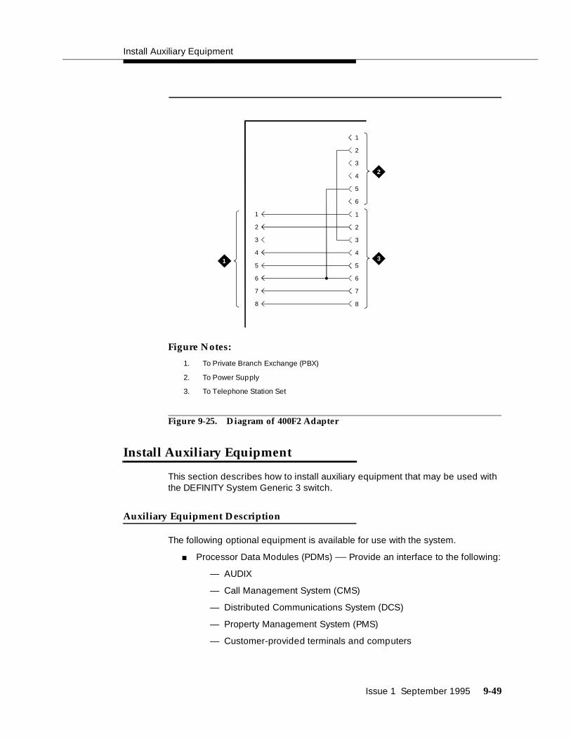
Install Auxiliary Equipment
Issue 1 September 1995 9-49
Figure Notes:
1. To Private Branch Exchange (PBX)
2. To Power Supply
3. To Telephone Station Set
Figure 9-25. Diagram of 400F2 Adapter
Install Auxiliary Equipment
This section describes how to install auxiliary equipment that may be used with the DEFINITY System Generic 3 switch.
Auxiliary Equipment Description
The following optional equipment is available for use with the system.
■ Processor Data Modules (PDMs) — Provide an interface to the following:
— AUDIX
— Call Management System (CMS)
— Distributed Communications System (DCS)
— Property Management System (PMS)
— Customer-provided terminals and computers
1
2
3
4
5
6
7
8
1
2
3
4
5
6
1
2
3
4
5
6
7
8
31
2

9-50 Issue 1 September 1995
— Station Message Detailed Recording (SMDR)
■ Asynchronous Data Units (ADU)— Provide an interface between the system data line circuit pack and the customer’s asynchronous data terminals and host computers. Asynchronous Data Units (ADU) can also be used to provide an interface to the Property Management System (PMS) or Station Message Detail Recording (SMDR) equipment.
Install Loudspeaker Paging and Music-on-Hold
The Loudspeaker Paging feature provides a connection from the TN763B/C/D auxiliary trunk to a customer-provided paging amplifier. Other Auxiliary-Trunk circuit packs may be required in some countries. All attendants and telephone users have access to the voice paging equipment.
The Music-on-Hold feature provides a connection from the analog line (TN2183) or auxiliary trunk (TN763) to a customer-provided music source. Other Auxiliary-Trunk circuit packs may be required in some countries. If music-on-hold is administered, all calls on hold, waiting in a queue, or parked receive music to let the waiting party know the connection is still in active.
Install Loudspeaker Paging Access withoutPaging Adapter
Requirements
Figure 9-26 shows the connections for the Loudspeaker Paging feature. These connections are used when the loudspeaker interface equipment is not located in the equipment room. If the loudspeaker interface equipment is located in the equipment room, the connections do not have to be routed through the wall jack. The connections are for one zone. Repeat connections for each paging zone.

Install Auxiliary Equipment
Issue 1 September 1995 9-51
Figure 9-26. Connections for Loudspeaker Paging without Universal Coupler
Install Loudspeaker Paging Access
Install loudspeaker paging access as follows:
1. Determine port assignment of paging zone(s) from Loudspeaker Paging Form:
2. Connect as shown in Figure 9-26.
Refer to Table 9-9 on page 9-17 for pinout information.
EXAMPLE: Port Number 2 B 02 01
Cabinet Carrier Slot Circuit
TR
TR
TR
SZSZ1
SS1
3
8
4
5
1 6
2 7
1. Loudspeaker system
2. Green
3. Red
4. 4-pair line cord
5. 103A or wall jack
6. Cross connect field
7. Auxiliary Trunk (TN763 circuit pack)
8. Generic 3 Cabinet
Figure Notes:

9-52 Issue 1 September 1995
Install Music-on-Hold Access
Requirements
An information outlet provides access to the music source. If the music source is Federal Communications Commission (FCC) registered, the switch side of the cross-connect field is connected directly to the switch cabinet.
If the music source is not Federal Communications Commission (FCC) registered to meet United States requirements, the switch side of the cross-connect field is connected to a 909A/B universal coupler. The 909A/B universal coupler is mounted in an auxiliary cabinet, if one is available.
If an auxiliary cabinet is not available, a connectorized wiring block must be locally engineered to replace the auxiliary cabinet ED-1E443-10 intra-connection panel.
The switch side of the cross-connect field is connected by the T and R leads to a TN763B/C/D auxiliary trunk circuit pack located in a port carrier. Other Auxiliary-Trunk circuit packs may be required in some countries.
Figure 9-27 shows the connections for the Music-on-Hold feature when the loudspeaker equipment is Federal Communications Commission (FCC) registered. Figure 9-28 shows the connections for the Music-on-Hold feature when the loudspeaker equipment is not Federal Communications Commission (FCC) registered.
The connections shown in Figure 9-27 and Figure 9-28 are used when the music source is not located in the equipment room. If the music source is located in the equipment room, the connections do not have to be routed through the cross-connect field.

Install Auxiliary Equipment
Issue 1 September 1995 9-53
Figure 9-27. Music-on-Hold/Dial Dictation, Federal Communications Commission (FCC) Registered Equipment (Auxiliary Access)
T
R
T
R
10 11
T
R
T
R
1
2 3
4
5
6 7
8
9
1. Dial Dictation Equipment or music Source
2. Red (R)
3. Green (T)
4. 103A or Wall Jack
5. Cross-Connect Field
6. R
7. T
8. Analog Line Circuit Pack (TN2183)
9. Generic 3i Cabinet
10. Cross-Connect Field
11. 122A Music Adapter
Figure Notes:

9-54 Issue 1 September 1995
Install Federal Communications Commission(FCC) Registered Music Source
To install Federal Communications Commission (FCC) registered music source:
1. Determine music feature port assignment from Feature-Related System Parameters Form:
2. Connect as shown Figure 9-27.
Install Recorded Announcement Equipment
This section describes how to install Recorded Announcement equipment.
Requirements
Recorded Announcement is available from external equipment, or internally from TN-750-type circuit packs. Connect external equipment as shown in Figure 9-28.
NOTE:To get the benefit of battery holdover for the TN750B circuit pack, install it in an Expansion Port Network (EPN) carrier position A.
EXAMPLE: Port Number 2 B 02 01
Cabinet Carrier Slot Circuit

Install Processor Data Modules (PDMs)
Issue 1 September 1995 9-55
Figure 9-28. Connections for non- Federal Communications Commission (FCC) Registered Recorded Announcement/Dial Dictation (Analog Access)
Install Processor Data Modules (PDMs)
Requirements
The interface between the system and many types of data equipment is provided by a TN754B digital line circuit pack connected to a Processor Data Module (PDM). Other digital-line circuit packs may be required in some countries. The following types of data equipment can be connected by a Processor Data Module (PDM):
■ AUDIX/Adjunct
■ AUDIX/Terminal
■ Call Management System (CMS)
■ Distributed Communications System (DCS)
■ Property Management System (PMS)
■ Journal Printer
■ Customer-provided terminals and host computers
■ Station message detail recording (SMDR)/ Call Detail Recording (CDR)
TR
TR
8
5
1 6
73
2
4
1. Recorded Announcement
2. Green
3. Red
4. Line cord
5. 103A or wall jack
6. Cross-connect field
7. Analog Line (TN2183) or Auxiliary Trunk (TN763)
8. Generic 3 Cabinet
Figure Notes:

9-56 Issue 1 September 1995
Processor Data Modules (PDMs) are connected to TN754B digital line circuit packs and are mounted individually or in a 71A data mounting. Other digital-line circuit packs may be required in some countries. Each 71A data mounting can contain up to eight modules. This document contains only the information required to connect the modules to the switch. Module installation and testing information is contained in AT&T System 75 User’s Guide—Processor Data Module, 999-700-028.
The data mounting is connected by an A25D/B25A cable through the cross-connect field to a TN754B digital line circuit pack. The modules can also be mounted and connected individually through the cross-connect field.
Installation
Connection to Data Mounting
1. From the Data Module Form, determine port assignment of the processor data modules (PDMs):
2. Connect an A25D or B25A cable to the DIGITAL COMMUNICATIONS PROTOCOL-LINE connector on the rear of the data mounting.
3. Route the cable from the data mounting to the station side of the cross-connect field.
4. Write the lead designations on the connecting block with a felt-tipped pen.
5. Connect patch cords/jumper wires at cross-connect field (Figure 5-1).
6. Administer according to the instructions in the following United States. English book:
■ DEFINITY Communications System Generic 3 Implementation, 555-230-655
EXAMPLE: Port Number 2 B 02 01
Cabinet Carrier Slot Circuit

Install Processor Data Modules (PDMs)
Issue 1 September 1995 9-57
Figure 9-29. Connections for Processor Data Modules (PDMs) in Data Mounting
Connection to Individual Processor Data Modules (PDMs)
1. Determine port assignment of the Processor Data Module (PDM) from the Data Module Form:
2. Install the module per instructions in AT&T System 75 User’s Guide—Processor Data Module, 999-700-028.
3. Install patch cord/jumper wires at cross-connect field.
EXAMPLE: Port Number 2 B 02 01
Cabinet Carrier Slot Circuit
2
3
8
4
9
5
76
1
TXTTXRPXTPXR
TXTTXRPXTPXR
1. Processor Data Module
2. Part of 25-pair connector in 71A multiple data mounting
3. Cross-connect field
4. Station side
5. Switch side
6. Yellow field
7. Purple field
8. Digital line circuit pack (TN754)
Figure Notes:
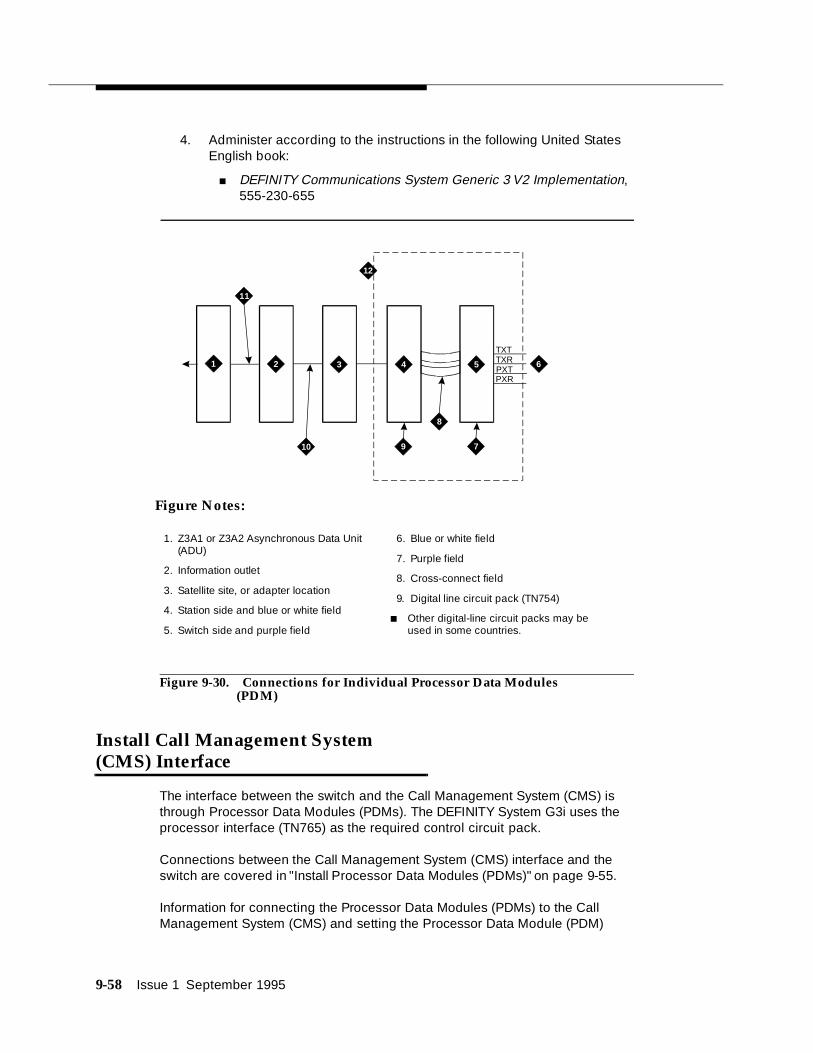
9-58 Issue 1 September 1995
4. Administer according to the instructions in the following United States English book:
■ DEFINITY Communications System Generic 3 V2 Implementation, 555-230-655
Figure 9-30. Connections for Individual Processor Data Modules (PDM)
Install Call Management System (CMS) Interface
The interface between the switch and the Call Management System (CMS) is through Processor Data Modules (PDMs). The DEFINITY System G3i uses the processor interface (TN765) as the required control circuit pack.
Connections between the Call Management System (CMS) interface and the switch are covered in "Install Processor Data Modules (PDMs)" on page 9-55.
Information for connecting the Processor Data Modules (PDMs) to the Call Management System (CMS) and setting the Processor Data Module (PDM)
2 3
8
4
9
5
10 7
61
12
TXTTXRPXTPXR
11
1. Z3A1 or Z3A2 Asynchronous Data Unit (ADU)
2. Information outlet
3. Satellite site, or adapter location
4. Station side and blue or white field
5. Switch side and purple field
6. Blue or white field
7. Purple field
8. Cross-connect field
9. Digital line circuit pack (TN754)
■ Other digital-line circuit packs may be used in some countries.
Figure Notes:

Install Property Management System (PMS) Interface
Issue 1 September 1995 9-59
option switches is contained in the 3B2 Messaging Server Installation and Maintenance Service Manual, 585-205-110.
The Call Management System (CMS) connection is illustrated below.
Figure 9-31. Typical Call Management System (CMS) Connections to DEFINITY System G3i Using Mode Conversion
Install Property Management System (PMS) Interface
This section describes how to install the Property Management System (PMS) interface.
Requirements
The interface between the switch and the customers Property Management System (PMS) can be through Processor Data Modules (PDMs). Such connection is covered in "Install Processor Data Modules (PDMs)" on page 9-55.
3 49
51
11
2
67 108
12 13
1. B25A
2. See PS6
3. DSW-87
4. M25B
5. See note 3
6. Cross-connect field
7. 103A or wall jack
8. Modular Processor Data Module (MPDM)
9. TN754 circuit pack
10. CMSAG 6386 PC
11. Generic 3i
12. 5000 Feet (1524 Meters)
13. 50 Feet (15 Meters)
Figure Notes:

9-60 Issue 1 September 1995
Refer to the vendor’s documentation for connecting to the Property Management System (PMS). The option switches on the Processor Data Module (PDM) must be set in accordance with the requirements for the customers Property Management System (PMS).
A journal printer can be used. The connections for the printer are the same as for the Property Management System (PMS). Refer to the vendor’s documentation for connecting the Processor Data Modules (PDMs) to the printer and for setting the option switches. The switches must be set according to the requirements for the printer.
The Property Management System (PMS) interface and the journal printers can be installed using Asynchronous Data Unit (ADUs). The connections are the same as for a customer-provided data terminal (Figure 9-32 on page 9-61).
Connections to a G3i switch can be switched connections through an Asynchronous Data Unit (ADU), through a modem or through the 7400A/B or 7500 data modules.+
2 3
8
4
9
5
10 7
61
12
TXTTXRPXTPXR
11

Install Customer-Provided Terminal Using Asynchronous Data Unit (ADU)
Issue 1 September 1995 9-61
Figure 9-32. Connections to Asynchronous Data Unit (ADU) for Data Terminal Equipment (DTE)
Install Customer-Provided Terminal Using Asynchronous Data Unit (ADU)
Requirements
The interface between the switch and the customer’s data terminals and host computer can be through Processor Data Modules (PDMs). Refer to section on installing Processor Data Modules (PDMs) for details.
Asynchronous data terminals, however, can be connected through a Z3A Asynchronous Data Unit (ADU) to a TN726B data line circuit pack (Figure 9-32). Normally, the data unit is powered from the connected data terminal. The data unit can also be remotely or locally powered using a 2012D transformer equipped with a 248B adapter. Data units connected to receive-only printers always require external power. The need for external power must be determined experimentally for data units connected to other devices. For more information on data unit installation, refer to the Z3A Asynchronous Data Unit User’s Manual, 555-401-701.
Installation
1. Determine data unit port assignment from Data Module Form:
2. Connect the RS-232 plug on the data unit to the data terminal.
EXAMPLE: Port Number 2 B 02 01
Cabinet Carrier Slot Circuit
1. Processor Data Module PDM)
2. Information outlet
3. Satellite site, or adapter location
4. Station side
5. Switch side
6. Digital Line Circuit Pack (TN754)
7. Purple field
8. Patch cord or jumpers
9. Blue or white field
10. Four pair line cord
11. Four pair line cord
12. Part of Cross-connect field
■ Other data-line circuit packs may be used in some countries.
Figure Notes:

9-62 Issue 1 September 1995
3. Refer to Figure 9-32 for an illustration.
Install Station Message Detail Recording (SMDR)/Call Detail Recording Unit (CDRU) Interface
The interface between the switch and Station Message Detail Recording (SMDR) can be through a Processor Data Module (PDM), Trunk Data Module (TDM), or 212-type modem.
For connections between the switch and the Processor Data Module (PDM) or Trunk Data Module (TDM), refer to the section on installing Processor Data Modules (PDMs).
The connection between the switch and the 212-type modem is the same as for external ringing (Figure 9-11). When a 212-type modem is used, an external pooled modem circuit pack must be provided. One of the pooled modem’s conversion resources is dedicated to the Station Message Detail Recording (SMDR) output device.
Connections between the G3i switch and an Asynchronous Data Unit (ADU) or data module are the same as for remote administration devices such as the Generic 3 Management Terminal (G3MT). These connections are shown in Figure 9-32 and Figure 9-33. All such connections require the mode 2 to mode 3 conversion resource shown in these figures.
Administer your connections as described in DEFINITY Communications System Generic 3 V2 Implementation, 555-230-655.
A TN726B data line circuit pack may also be used. If so, Processor Data Modules (PDMs), Trunk Data Modules (TDMs), or 212-type modems are not required for the data terminal equipment (DTE). Connections between the switch and the Station Message Detail Recording (SMDR) output receiving device is the same as a customer-provided data terminal (Figure 9-33).
The Station Message Detail Recording (SMDR) output device can be connected directly to the data communications equipment (DCE) connector on the rear of the control carrier. This connection is made using a RS-232 cable. A Processor Data Module (PDM) or Trunk Data Module (TDM), modem, or Asynchronous Data Unit (ADU) is required.

Install Station Message Detail Recording (SMDR)/Call Detail Recording Unit (CDRU) Interface
Issue 1 September 1995 9-63
Interface Cabling to Station Message DetailRecording (SMDR) Output Device
Figure 9-33 shows the cabling required to connect the TELESEER unit, printer, or customer-provided data terminal equipment (DTE) for an AC-powered single-carrier cabinet. The M25B/RS-232 cable connects to the PI connector on the TELESEER unit.
! CAUTION:All peripherals connected to a DC-powered switch through the asynchronous Electronic Industries Association (EIA) RS-232 data terminal equipment interface on the Processor Port Network (PPN) A or B carrier or the Expansion Port Network (EPN) maintenance circuit pack require an Electronic Industries Association (EIA) 116A ground isolator. Plug the 116A ground isolator into the RS-232 interface connector (labelled DTE on the back of cabinet). The cable from the peripheral equipment is then plugged into the opto-isolator. Figure 9-33 shows the connections for a DC-powered single-carrier cabinet.
The apparatus code for the isolator is 116A ground isolator and the AT&T Comcode is 106005242.
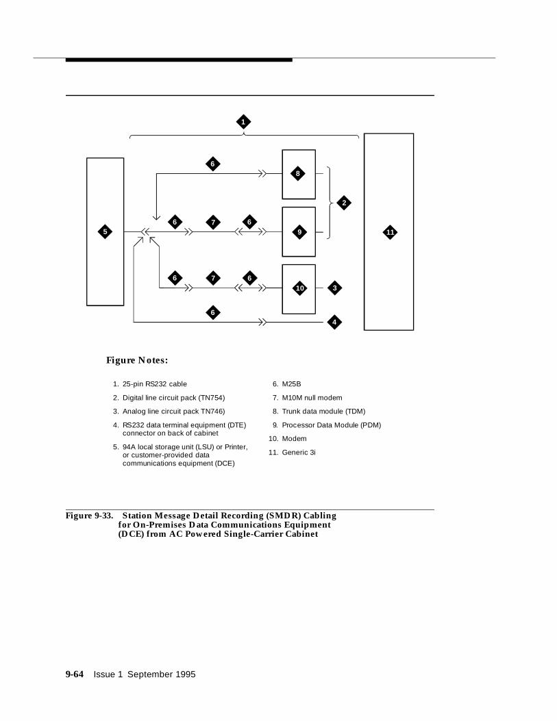
9-64 Issue 1 September 1995
Figure 9-33. Station Message Detail Recording (SMDR) Cabling for On-Premises Data Communications Equipment (DCE) from AC Powered Single-Carrier Cabinet
2
3
8
4
95
10
11
7
7
6
6 6
6 6
6
1
1. 25-pin RS232 cable
2. Digital line circuit pack (TN754)
3. Analog line circuit pack TN746)
4. RS232 data terminal equipment (DTE) connector on back of cabinet
5. 94A local storage unit (LSU) or Printer, or customer-provided data communications equipment (DCE)
6. M25B
7. M10M null modem
8. Trunk data module (TDM)
9. Processor Data Module (PDM)
10. Modem
11. Generic 3i
Figure Notes:

Install Station Message Detail Recording (SMDR)/Call Detail Recording Unit (CDRU) Interface
Issue 1 September 1995 9-65
Figure 9-34 shows the connections for a remote host connected by a private line.
Figure Notes:
Figure 9-34. Station Message Detail Recording (SMDR) Cabling for Remote Host
Switch Settings for Processor Data Module(PDM), Trunk Data Module (TDM), or 212-TypeModem
Set the option switches for the Processor Data Module (PDM) and the Trunk Data Module (TDM) as follows:
Switch Setting
SELF TEST OFF
LOC LOOP/REM LOOP OFF
1200 ON
AANS (Processor Data Module (PDM) Only)
ON
SIGLS ON
PRTY ON
1/0D ON
All Others OFF
1
3
45
2
1. Analog Line or Central Office (CO) Trunk
2. Modem or Digital Service Unit (DSU)
3. 25-Pin Cable
4. Trunk Data Module (TDM)
5. M25B Cable

9-66 Issue 1 September 1995
212-Type Modem Switch Setting
Set the option switches for the 212-type modem as follows:
Implement and Administer System Data
After the hardware is installed and the system is activated, the data for system and telephone features can be administered. The implementation procedures are provided in the United States English book, DEFINITY Communications System Generic 3 Implementation, 555-230-655.
NOTE:For easier reference, installation steps and test steps are grouped in separate chapters. It may be more efficient to install each hardware component, administer it, and then test it before going on to install another component. As an example, install the attendant console using the procedures in Chapter 9, "Install and Wire Telephones and Other Equipment", administer it using the procedures in the book listed above, and test it using the procedures in Chapter 10, "Test Telephones and Other Equipment".
Switch Setting
AL OFF
ST OFF
RDL OFF
DL OFF
HS ON
Issue 1 September 1995 10-1
10Test Telephones and Other Equipment
This chapter describes how to test the telephones and other equipment. The following tests are included in this chapter:
1. Make test calls (single-cabinet switch)
2. Make test calls (two-cabinet switch)
3. Make test calls (three-cabinet switch)
4. Test the attendant console
5. Test the selector console
6. Test External Ringing
7. Test Queue Warning Indicator
8. Test Integrated Announcement
9. Test Music-on-Hold
10. Test Emergency Transfer
11. Test remote access interface (known as Initialization and Administration System (INADS))
12. Test Basic Rate Interface (BRI)
NOTE:The tests in this chapter are performed after the equipment has been wired to the switch and after the customer’s data for that equipment has been administered.
For easier reference, installation steps and test steps are grouped in separate chapters. It may be more efficient to install each hardware component, administer it, and then test it before going on to install another component. As an example, install the attendant console using the procedures in Chapter 9, "Install

Test Telephones and Other Equipment
10-2 Issue 1 September 1995
and Wire Telephones and Other Equipment", administer it using the procedures in the United States English book, DEFINITY Communications System Generic 3 Implementation, 555-230-655, and test it using the procedures in this chapter.
The following tests are acceptance tests or sanity tests and they provide some assurance the system will perform properly after installation and administration. If problems occur or more extensive or specific tests are required, refer to the United States English book, DEFINITY Communications System Generic 1 and Generic 3i/s/vs Maintenance, 555-204-105.
Make Test Calls (Single-Cabinet Switch)
Description
Make two calls from one telephone to another telephone. Make the first call by dialing a telephone and make the second call by dialing a trunk access code and a listed directory number (LDN).
Procedure
1. Select a working telephone and pick up the receiver. Dial tone is heard.
2. Dial the extension number of another working telephone. Ringback is heard through the earpiece of the test telephone.
3. Answer the call at the called telephone. The conversation must be satisfactory.
4. Hang up both telephones.
5. At the test telephone, pick up the receiver. Dial tone is heard.
6. Dial the trunk access code. Dial tone is heard.
7. Dial a listed directory number (LDN) for a working telephone. Ringback is heard through the earpiece of the test telephone.
8. At the called telephone, answer the call. The conversation must be satisfactory.
9. Hang up both telephone.

Make Test Calls (Two-Cabinet Switch)
Issue 1 September 1995 10-3
Make Test Calls (Two-Cabinet Switch)
Description
To test a two-cabinet switch, you will make the following calls:
■ Make a call from a telephone associated with a line port in the Processor Port Network (PPN) to a telephone associated with another line port in the Processor Port Network (PPN).
■ Make a call from a telephone associated with a line port in the Processor Port Network (PPN) to a telephone associated with a line port in the Expansion Port Network (EPN).
■ Make a call from a telephone associated with a line port in the Processor Port Network (PPN) to a listed directory number (LDN).
■ Make a call from a telephone associated with a line port in the Expansion Port Network (EPN) to a telephone associated with a line port in the Expansion Port Network (EPN).
■ Make a call from a telephone associated with a line port in the Expansion Port Network (EPN) to a associated with a line port in the Processor Port Network (PPN).
■ Make a call from a telephone associated with a line port in the Expansion Port Network (EPN) to a listed directory number (LDN).
Procedure
1. Select a working telephone associated with a line port in the Processor Port Network (PPN) as the test telephone and lift the receiver. Dial tone is heard.
2. Dial the extension number of a working telephone associated with a line port in the Processor Port Network (PPN). Ringback is heard through the earpiece of the test telephone.
3. At the called telephone, answer the call. Conversation must be satisfactory.
4. Hang up both telephones.
5. At the test telephone, lift the receiver.
6. Dial the extension number of a working telephone associated with a line port in the Expansion Port Network. Ringback is heard through the earpiece of the test telephone.
7. At the called telephone, answer the call. Conversation must be satisfactory.
8. Hang up both telephones.
9. At the test telephone, lift the receiver. Dial tone is heard.

Test Telephones and Other Equipment
10-4 Issue 1 September 1995
10. Dial the trunk access code. Dial tone is heard.
11. Dial a listed directory number (LDN) for a working telephone. Ringback is heard through the earpiece of the test telephone.
12. At the called telephone, pick up the receiver. Conversation must be satisfactory.
13. Hang up both telephones.
14. Select a working telephone associated with a line port in the Expansion Port Network (EPN) as the test telephone and lift the receiver. Dial tone is heard.
15. Dial the extension number of a working telephone associated with a line port in the Expansion Port Network (EPN) cabinet. Ringback is heard through the earpiece of the test telephone.
16. At the called telephone, answer the call. Conversation must be satisfactory.
17. Hang up both telephones.
18. At the test telephone, pick up the receiver.
19. Dial the extension number of a working telephone associated with a line port in the Processor Port Network (PPN). Ringback is heard through the earpiece of the test telephone.
20. At the called telephone, pick up the receiver. Conversation is satisfactory; hang up the receiver at both telephones.
21. At the test telephone, pick up the receiver. Dial tone is heard.
22. Dial the trunk access code. Dial tone is heard.
23. Dial the listed directory number (LDN) for a working telephone. Ringback is heard through the earpiece of the test telephone.
24. At the called telephone, pick up the receiver. Conversation must be satisfactory.
25. Hang up both telephones.
Make Test Calls (Three-Cabinet Switch)
Description
To test a three-cabinet switch, make the following calls:
■ Make a call from a telephone associated with a line port in the Processor Port Network (PPN) to a telephone associated with a line port in the Processor Port Network (PPN) .

Make Test Calls (Three-Cabinet Switch)
Issue 1 September 1995 10-5
■ Make a call from a telephone associated with a line port in the Processor Port Network (PPN) to a telephone associated with a line port in the Expansion Port Network1 (EPN).
■ Make a call from a telephone associated with a line port in the Processor Port Network (PPN) to a telephone associated with a line port in the Expansion Port Network2 (EPN).
■ Make a call from a telephone associated with a line port in the Processor Port Network (PPN) to a listed directory number (LDN).
■ Make a call from a telephone associated with a line port in the Expansion Port Network1 (EPN) to a telephone associated with a line port in the Expansion Port Network1 (EPN).
■ Make a call from a telephone associated with a line port in the Expansion Port Network1 (EPN) to a telephone associated with a line port in the Expansion Port Network2 (EPN).
■ Make a call from a telephone associated with a line port in the Expansion Port Network1 (EPN) to a telephone associated with a line port in the Processor Port Network (PPN).
■ Make a call from a telephone associated with a line port in the Expansion Port Network1 (EPN) to a listed directory number (LDN).
■ Make a call from a telephone associated with a line port in the Expansion Port Network2 (EPN) to a telephone associated with a line port in the Expansion Port Network2 (EPN).
■ Make a call from a telephone associated with a line port in the Expansion Port Network2 (EPN) to a telephone associated with a line port in the Expansion Port Network1 (EPN).
■ Make a call from a telephone associated with a line port in the Expansion Port Network2 (EPN) to a telephone associated with a line port in the Processor Port Network (PPN).
■ Make a call from a telephone associated with a line port in the Expansion Port Network2 (EPN) to a listed directory number (LDN).
Procedure
1. Select a working telephone associated with a line port in the Processor Port Network (PPN) as the test telephone, and pick up the receiver. Dial tone is heard.
2. Dial the extension number of a working telephone associated with a line port in the Processor Port Network (PPN) . Ringback is heard through the earpiece of the test telephone.
3. At the called telephone, pick up the receiver. Conversation must be satisfactory.
4. Hang up both telephones.
5. At the test telephone, pick up the receiver.

Test Telephones and Other Equipment
10-6 Issue 1 September 1995
6. Dial the extension number of a working telephone associated with a line port in Expansion Port Network1 (EPN) . Ringback is heard through the earpiece of the test telephone.
7. At the called telephone, pick up the receiver. Conversation must be satisfactory.
8. Hang up both telephones.
9. At the test telephone, pick up the receiver.
10. Dial the extension number of a working telephone associated with a line port in Expansion Port Network2 (EPN). Ringback is heard through the earpiece of the test telephone.
11. At the called telephone, pick up the receiver. Conversation must be satisfactory.
12. Hang up both telephones.
13. At the test telephone, pick up the receiver. Dial tone is heard.
14. Dial a trunk access code. Dial tone is heard.
15. Dial the listed directory number (LDN) for a working telephone. Ringback is heard through the earpiece of the test telephone.
16. At the called telephone, pick up the receiver. Conversation must be satisfactory.
17. Hang up both telephones.
18. Select a working telephone associated with a line port in Expansion Port Network1 (EPN) as the test telephone and pick up the receiver. Dial tone is heard.
19. Dial the extension number of a working telephone associated with a line port in Expansion Port Network1 (EPN) cabinet. Ringback is heard through the earpiece of the test telephone.
20. At the called telephone, pick up the receiver. Conversation must be satisfactory.
21. Hang up both telephones.
22. At the test telephone, pick up the receiver.
23. Dial the extension number of a working telephone associated with a line port in the Expansion Port Network2 (EPN). Ringback is heard through the earpiece of the test telephone.
24. At the called telephone, pick up the receiver. Conversation must be satisfactory.
25. Hang up both telephones.
26. At the test telephone, pick up the receiver.

Make Test Calls (Three-Cabinet Switch)
Issue 1 September 1995 10-7
27. Dial the extension number of a working telephone associated with a line port in the Processor Port Network (PPN). Ringback is heard through the earpiece of the test telephone.
28. At the called telephone, pick up the receiver. Conversation must be satisfactory.
29. Hang up both telephones.
30. At the test telephone, pick up the receiver. Dial tone is heard.
31. Dial trunk access code. Dial tone is heard.
32. Dial the listed directory number (LDN) for a working telephone. Ringback is heard through the earpiece of the test telephone.
33. At the called telephone, pick up the receiver. Conversation must be satisfactory.
34. Hang up both telephones.
35. Select a working telephone associated with a line port in Expansion Port Network2 (EPN) as the test telephone and pick up the receiver. Dial tone is heard.
36. Dial the extension number of a working telephone associated with a line port in Expansion Port Network2 (EPN) cabinet. Ringback is heard through the earpiece of the test telephone.
37. At the called telephone, pick up the receiver. Conversation must be satisfactory.
38. Hang up both telephones.
39. At the test telephone, pick up the receiver.
40. Dial the extension number of a working telephone associated with a line port in the Expansion Port Network1 (EPN). Ringback is heard through the earpiece of the test telephone.
41. At the called telephone, pick up the receiver. Conversation must be satisfactory.
42. Hang up both telephones.
43. At the test telephone, pick up the receiver.
44. Dial the extension number of a working telephone associated with a line port in the Processor Port Network (PPN). Ringback is heard through the earpiece of the test telephone.
45. At the called telephone, pick up the receiver. Conversation must be satisfactory.
46. Hang up both telephones.
47. At the test telephone, pick up the receiver. Dial tone is heard.
48. Dial the trunk access code. Dial tone is heard.

Test Telephones and Other Equipment
10-8 Issue 1 September 1995
49. Dial the listed directory number (LDN) for a working telephone. Ringback is heard through the earpiece of the test telephone.
50. At the called telephone, pick up the receiver. Conversation must be satisfactory.
51. Hang up both telephones.
Test the Attendant Console
Description
Check all lamps are operational and call another telephone in the system.
Procedure
1. Open front panel of console, press and hold Test or Self-Test switch.
2. Verify all lamps on display light and remain lighted. Each row of lamps on the console lights and goes dark in sequence from top to bottom.
3. Press Start.
Listen for dial tone.
Atnd or green lamp associated with idle call appearance button lights.
Pos Avail or Avail lamp goes dark.
4. Dial number associated with a working telephone. Audible ringing tone is heard in ear piece.
5. Press Release.
Audible ringing tone is silenced.
Atnd or green lamp goes dark.
Pos Avail or Avail lamp lights.

Test the Selector Console
Issue 1 September 1995 10-9
Test the Selector Console
Description
Check that all selector console lamps are operational. Make call to a telephone in the system.
Procedure
1. Open front panel of attendant console, press and hold Test or Self-Test switch.
2. Each row of lamps on the selector console lights and goes dark in sequence from top to bottom.
3. Press hundreds group select button.
Hundreds group select lamp lights and any lamps associated with busy telephone light.
4. Press Direct Extension Selection (DXS) button for the desired extension.
Audible ringing tone is heard in the earpiece on attendant console.
5. On attendant console, press Release.
Audible ringing tone is silenced.
Test External Ringing
Description
Make test call to attendant console to verify ringing device sounds when Night lamp on console is lighted. If ringing device has not yet been installed by customer, connect spare telephone to information outlet reserved for ringing device and make test call.
Procedure—Ringing Device Installed
1. On G1, press the Night key.
2. Verify the Night lamp lights.
3. Select a working telephone as a test telephone.
4. At the test telephone, pick up the receiver, dial a trunk access code and the listed directory number (LDN) for the attendant console.
5. Verify the ringing device sounds.

Test Telephones and Other Equipment
10-10 Issue 1 September 1995
6. At the test telephone, hang up the receiver.
7. On the attendant console, press Night key.
8. Verify Night lamp goes dark.
Procedure—Ringing Device Not Installed
1. Connect a spare 2500-type telephone to the information outlet indicated on the console parameters screen.
2. On the attendant console, press Night key.
3. Verify Night lamp lights.
4. Select a working telephone as the test telephone.
5. At the test telephone, pick up the receiver, dial a trunk access code and the listed directory number for the attendant console.
6. Verify ringing is heard on the spare telephone.
7. At the test telephone, hang up the receiver.
8. Disconnect the spare telephone from the information outlet.
9. Press the Night key on the attendant console.
10. Verify the Night lamp goes off.
11. Notify the customer that installation is complete and the external ringing device can be installed.
Test Queue Warning Indicator
Description
Make a test call to an extension associated with a Uniform Call Distribution (UCD) or Direct Department Calling (DDC) group, and verify the queue warning indicator lamp lights. If the queue warning indicator has not yet been installed by customer, connect a spare telephone to the information outlet reserved for queue warning indicator and make a test call.
Procedure—Queue Warning Indicator Installed
1. Administer Queue Warning Indicator number to 0 on Hunt Group Screen. Record old number.
2. Make sure all telephones in the group are disconnected or are “busy.”
3. Select a working telephone as the test telephone.

Test Queue Warning Indicator
Issue 1 September 1995 10-11
4. At the test telephone, pick up the receiver and dial the number associated with a uniform call distribution (UCD) or a direct department calling (DDC) group.
5. Verify the lamp lights (see the following note).
NOTE:Delay Recorded Announcement is heard if it is administered for this group. The delay announcement is followed by music if Music-on-Hold is administered.
6. At the test telephone, hang up the receiver.
7. Administer queue warning threshold number to number changed in Step 1.
8. Restore service to all telephones made busy or disconnected in Step 2.
Procedure—Queue Warning Indicator NotInstalled
1. Administer Queue Warning Indicator number to 0 on Hunt Group Screen. Record old number.
2. Make sure all telephones in the group are disconnected or are “busy.”
3. Connect a spare 2500-type telephone to an information outlet.
4. Select a working telephone as the test telephone.
5. At the test telephone, pick up the receiver and the dial number associated with a uniform call distribution (UCD) or a direct department calling (DDC) group.
6. Verify ringing is heard on the spare telephone (see the following note).
NOTE:Delay Recorded Announcement is heard at the test telephone if it is administered for this group. The delay announcement is followed by music if Music-on-Hold is administered.
7. At the test telephone, hang up the receiver.
8. Disconnect the spare telephone from the information outlet.
9. Administer queue warning threshold number to number changed in Step 1.
10. Restore service to all telephones made busy or disconnected in Step 2. Notify customer that installation is complete and that queue warning indicator lamp can be installed.

Test Telephones and Other Equipment
10-12 Issue 1 September 1995
Test Integrated Announcement
Description
The TN750 Announcement circuit pack provides the ability to store messages. The messages can be recorded from telephones on- or off-premises and have flexible message lengths.
The telephone selected as the test telephone must have a class of service (COS) with console permission enabled.
Procedure — Record Announcement
1. Select test telephone with console permission enabled.
2. Dial access code followed by the integrated announcement extension number. Dial Tone is heard.
3. Dial “1.” A short burst of tone is heard and recording begins.
4. Speak the announcement into the telephone.
5. When you have finished recording the announcement, dial “#” or hang up. Recording stops and dial tone is heard.
Procedure — Playback Announcement
1. Dial access code followed by the integrated announcement extension number. Dial Tone is heard.
2. Dial “2.” The announcement is heard and dial tone is heard at completion of announcement.
Procedure —Delete Announcement
1. Dial access code followed by the integrated announcement extension number. Dial Tone is heard.
2. Dial “3.” A confirmation tone is heard and announcement is deleted.

Test Music-on-Hold
Issue 1 September 1995 10-13
Test Music-on-Hold
Description
Verify music is provided to a held party during any hold interval.
Procedure
1. Select a working telephone as the test telephone.
2. At the test telephone, pick up the receiver and dial 0 for the attendant console.
3. At attendant console, answer call by pressing call appearance button (a through f ) associated with the flashing Atnd lamp. The audible alert stops. Atnd lamp lights steadily.
4. Press Hold at attendant console. The Hold lamp associated with the call appearance button lights.
5. Verify music is heard at the test telephone.
6. Hang up the test telephone.
Test Emergency Transfer
Description
Put system in emergency transfer mode and make call using emergency transfer telephone.
There may be one, two, three, or four Emergency Transfer switches, depending on the system configuration. The switch is located on the Processor circuit pack(s) in the Processor Port Network (PPN) control carrier, and the switch is located on the Maintenance circuit pack in the Expansion Port Network (EPN) control carrier.
The Expansion Port Network (EPN) cabinets may be tested separately from the Processor Port Network (PPN) cabinets in any system, but the Processor Port Network (PPN) cabinets in a high or critical-reliability system must have both switches set to the ON position to invoke Emergency Transfer.

Test Telephones and Other Equipment
10-14 Issue 1 September 1995
Procedure
1. At control carrier, set Emergency Transfer switch(es) to ON position. See Note.
NOTE:Pull out on Switches to overcome detents.
2. At emergency transfer telephone connected to the port network being tested, pick up the receiver and press Ground Start key, if so equipped. Dial tone is heard.
3. Dial number associated with an outside number. Audible ringing or busy tone is heard.
4. Hang up the test telephone.
5. At control carrier, set Emergency Transfer switch(es) to AUTO position.
Test Remote Access Interface (known as Initialization and Administration System)
Description
Test the communication link between the switch and Initialization and Administration System (INADS) and verify the alarm notification process. Make a remote test from Initialization and Administration System (INADS) to the system and a local test from the system to Initialization and Administration System (INADS).
NOTE:In some countries, this remote access interface is not allowed. Check with your AT&T representative.
Procedure—Remote Test
1. Call outside personnel who will be accessing the switch remotely to perform administration, maintenance, and testing.
2. Ask remote access personnel to call system and login and display System Parameters Maintenance screen. The login must be successful.
NOTE:Requirement: Product Identification on the System Parameters screen must match the Product Identification administered by the local technician.

Test Basic Rate Interface (BRI)
Issue 1 September 1995 10-15
3. Remote access personnel enters test inads-link command, terminates login, and disconnects.
4. Remote access personnel then check the appropriate trouble ticket. The trouble ticket should show ‘‘INADS,n,MINOR’’ in the description field to indicate a minor off-board alarm was reported to the remote access personnel. There may be additional text in the description field if other resolved alarms were reported.
5. Remote access personnel make second call and login to system and checks the error log to verify no problems. See DEFINITY Communications System Generic 1 and Generic 3i/s/vs Maintenance, 555-204-105, or DEFINITY Communications System Generic 3r Maintenance, 555-230-105, for error log and error code information.
6. Remote access personnel terminate login and disconnects.
Procedure—Local Test
1. Log in and enter test inads-link command.
2. Request remote access personnel to verify a trouble ticket was created.
3. Check error log to verify no problems.
4. Log off the system.
Test Basic Rate Interface (BRI)
Description
Check for normal voice telephone function (dial tone, ability to make and receive calls). Check for the correct Service Profile Identifier (SPID) on a display Telephone and the G3 Management Terminal (G3-MT).
Procedure—Dial Tone
1. Lift handset of Basic Rate Interface (BRI) telephone and listen for dial tone.
Procedure—Make and Receive Calls
1. Select a working telephone with display and dial that telephone’s extension number from the Basic Rate Interface (BRI) test telephone. The called telephone rings.
2. At the called telephone, pick up the receiver. Conversation must be satisfactory.

Test Telephones and Other Equipment
10-16 Issue 1 September 1995
3. Verify the extension number of the calling telephone is displayed on the display of the called telephone. The extension must be correct.
4. Hang up both telephones.
5. Call the Basic Rate Interface (BRI) test telephone from the other telephone. The Basic Rate Interface (BRI) test telephone rings.
6. Verify the name and extension of the called Basic Rate Interface (BRI) test telephone is correct as displayed on the calling telephone.
7. Hang up both telephones.
Procedure—Checking the Service ProfileIdentifier (SPID)
This test requires a display telephone at the test telephone station.
1. Use appropriate procedures to display the Service Profile Identifier (SPID) on the test telephone. Procedures differ depending on the model of telephone being used. The Service Profile Identifier (SPID) must be correct.

Issue 1 September 1995 A-1
AApproved Grounds
This chapter describes the approved grounds appropriate for the single-carrier cabinets.
Definition of Approved Ground
An approved ground is the closest acceptable medium for grounding the building entrance protector, entrance cable shield, or single-point ground of electronic Private Branch Exchange (PBX) equipment.
If more than one type of approved ground is available on the premises, the grounds must be bonded together as required in Section 250-81 of the National Electrical Code (NEC), or the applicable code in your country.
Acceptable Mediums for Protective Ground
The following protective ground types are acceptable:
Grounded Building Steel. — The metal frame of the building where it is effectively grounded by one of the following grounds: acceptable metallic water pipe, concrete encased ground, or a ground ring.
Acceptable Water Pipe. — A metal underground water pipe, at least 1/2 inch (1.3 cm) in diameter, in direct contact with the earth for at least 10 feet (3 meters). The pipe must be electrically continuous (or made electrically continuous by bonding around insulated joints, plastic pipe, or plastic water meters), to the point where the protector ground wire is connected. A metallic underground water pipe must be supplemented by the metal frame of the building, a concrete

Approved Grounds
A-2 Issue 1 September 1995
encased ground, or a ground ring. If these grounds are not available, the water pipe ground can be supplemented by one of the following types of grounds:
■ Other local metal underground systems or structures — Local underground structures such as tanks and piping systems
■ Rod and pipe electrodes — A 5/8 inch (1.6 cm) (solid rod) or 3/4 inch(1.9 cm) (conduit or pipe) electrode driven to a minimum depth of 8 feet (2.5 meters)
■ Plate electrodes — Must have a minimum of 2 square feet (0.6 sq. meter) of metallic surface exposed to the exterior soil
Concrete Encased Ground. — An electrode encased by at least 2 inches (5 cm) of concrete and located within and near the bottom of a concrete foundation or footing in direct contact with the earth. The electrode must be at least 20 feet (6 meters) of one or more steel reinforc ing bars or rods 1/2 inch (1.3 cm) in diameter, or at least 20 feet (6 meters) of bare, solid copper, 4 AWG wire.
Ground Ring. — A buried ground that encircles a building or structure at a depth of at least 2-1/2 feet (0.8 meter) below the earth's surface. The ground ring must be at least 20 feet (6 meters) of 2-AWG, bare, copper wire.
Approved Floor Grounds
Approved floor grounds are those grounds on the floor of each high-rise building suitable for connection to the ground terminal in the riser closet and to the Private Branch Exchange (PBX) equipment single-point ground terminal. Approved floor grounds may include the following:
■ Building steel
■ The grounding conductor for the secondary side of the power transformer feeding the floor
■ Metallic water pipes
■ Power feed metallic conduit supplying panel boards on the floor
■ A grounding point specifically provided in the building for the purpose
! WARNING:If the approved ground or approved floor ground can only be accessed inside a dedicated power equipment room, then connections to this ground should be made by a licensed electrician.
NOTE:All protective grounds must be electrically connected together to form a single grounding electrode system.

Issue 1 September 1995 B-1
BEarthquake Protection Procedures
This appendix describes earthquake protection installation procedures to perform if your site experiences earthquake activity.
Use the following procedures to install earthquake protection for your cabinets.
Install Floor Mounting to Attach Cabinet to Floor
Attach your DEFINITY System Generic 3 (G3) cabinets to the floor by completing the following steps:
1. Place the Front Mounting Angle at the location selected for the front of the control cabinet.
2. Using the angle as the template, mark the location of the mounting bolts.
3. Drill two holes 1/2-inch (1.3 cm) in diameter and 1-1/2 (3.8 cm) inches deep at the spot marked in Step 2.
4. Mount the Front Mounting Angle to the floor (see Figure B-1).

Earthquake Protection Procedures
B-2 Issue 1 September 1995
Figure B-1. Front Mounting Angle—Concrete Floor
5. Move the cabinet back into place and attach the cabinet to the angle with two #12-24x1/2-inch (1.3 cm) thread-forming screws.
6. Insert a pencil or marker through holes in the lower back of the cabinet and mark the floor directly beneath each hole.
7. Move the cabinet out of the way.
8. Drill two holes 1/2-inch (1.3 cm) in diameter and 1-1/2-inches (3.8 cm) deep at the spot marked in Step 6.
9. Move the cabinet back into place.
2
4
7
5
1
3
6
1. Screw
2. Cabinet
3. Mounting angle
4. Bolt
5. Nylon insulating washer
6. Floor
7. Concrete anchor
Figure Notes:

Install Floor Mounting to Attach Cabinet to Floor
Issue 1 September 1995 B-3
10. Attach the cabinet to the front mounting angle using four #12-24 by 1/2-inch (1.3 cm) thread forming screws.
11. In the back of the cabinet, lay the stiffener on the bottom of the cabinet, aligning the stiffener with the holes in the bottom of the cabinet.
12. Fasten the cabinet to the floor (see Figure B-2).
Figure B-2. Cabinet Earthquake Mounting—Concrete FloorSide View
If critical reliability is provided, Cabinet B will be another control cabinet.
4
1
3
2
5
6
7
Figure Notes:
1. Cabinet
2. Nylon Insulating Washer (2 Required)
3. Hex Bolt (2 Required)
4. Stiffener
5. Cabinet Foot
6. Floor
7. Concrete Anchor

Earthquake Protection Procedures
B-4 Issue 1 September 1995
Install Ground Plates on Cabinet Backs
The ground plate provides the ground connection between cabinets, provides radio frequency (RF) radiation protection, and also stabilizes the cabinets.
A ground plate is required between each cabinet (see Figure B-3). Complete the following steps to attach the ground plate.
1. At the back of the cabinets, put in all the screws on the upper and lower panels, except for the screws that run along the top and bottom of each cabinet.
2. At the upper cabinet, place the top of the ground plate over the bottom of the lower-back panel. Align the four holes in the ground plate with the four holes at the bottom of the lower back cover of the cabinet and insert the screws. Do not tighten the screws yet.
3. At the top of the cabinet below the cabinet referred to in Step 2, align the bottom of the ground plate with the top four holes in the upper back cover of the lower cabinet. Insert the four screws. Do not tighten the screws yet.
4. Repeat Steps 2 and 3 until the earthquake ground plates are installed between all cabinets.
5. Tighten all screws.
Install Front Plates
For earthquake protection and electromagnetic shielding (as required by CISPR 22 regulations), use the front plate instead of the cabinet clip to attach the cabinets to each other. Use one front plate between each cabinet. (Figure B-3).
Complete the following steps to install the front plates to the cabinet:
1. At the front of the cabinets, align the holes in the top of the earthquake front plate with the holes at the bottom of the upper cabinet, and insert the four screws. Do not tighten the screws yet.
2. At the front of the cabinets, align the holes in the bottom of the earthquake front plate with the holes at the top of the lower cabinet, and insert the four #12-24 by 1/2-inch (1.27 cm) thread-forming screws. Do not tighten the screws yet.
3. Repeat Steps 1 and 2 until all the cabinets are fastened together with the earthquake front plate.
4. Tighten all screws.

Install Front Plates
Issue 1 September 1995 B-5
Figure Notes:
Figure B-3. Single-Carrier Cabinet Ground Plate, Front Plate,and Battery Locations
1
2
3
1. Front Plate
2. Battery
3. Back Plate
■ Side View of 2-Cabinets Port Network

Issue 1 September 1995 C-1
CDEFINITY AUDIX System Power Procedures
Manually Power Down DEFINITY AUDIX System
A yellow caution sticker is placed on the switch’s power unit telling technicians to shut down the DEFINITY AUDIX System prior to powering down the switch.
To shutdown the DEFINITY AUDIX system, do the following:
1. Using a pointed object, such as a paper clip or pen (do not use a pencil), press the Boot/Shutdown button (See A on Figure C-1).
2. Hold Boot/Shutdown button in until Liquid Crystal Display (LCD) (see B in Figure C-1) flashes the message: MSHUT.
3. Release Boot/Shutdown button.
NOTE:DEFINITY AUDIX System takes approximately five minutes to shut down. The following sequence of events will happen during shutdown:
■ Display (See B on Figure C-1) flashes the message: MSHUT.
■ About two and a half minutes into shutdown, the display flashes the message, TEST, and the red light emitting diode (LED) (See C on Figure C-1) is steady on.
■ The DEFINITY AUDIX System is now powered down.

DEFINITY AUDIX System Power Procedures
C-2 Issue 1 September 1995
NOTE:Even though the DEFINITY AUDIX System is shutdown, the “heartbeat” indication on the display continues to flash.
NOTE:Upon the switch powering up, DEFINITY AUDIX System will automatically reboot. This sequence may show an MD or MJ ADX alarm in the display until the switch has powered up. When the switch has completed its power up sequence, the DEFINITY AUDIX System display will read: ADX.

Manual Power Up DEFINITY AUDIX System
Issue 1 September 1995 C-3
Figure Notes:
Figure C-1. DEFINITY AUDIX System
Manual Power Up DEFINITY AUDIX System
To power up the DEFINITY AUDIX System, do the following:
1. Using a pointed object such as a paper clip or a pen (do not use a pencil), press the Boot/Shutdown button.
3
1
2
1. Boot/Shutdown Button
2. Liquid Crystal Display (LCD)
3. Red Light Emitting Diode (LED)

DEFINITY AUDIX System Power Procedures
C-4 Issue 1 September 1995
2. Hold Boot/Shutdown button in until the display indicates the message, BTEST, steady on.
3. Release Boot/Shutdown button.
NOTE:DEFINITY AUDIX System takes approximately five minutes to power up. The following occurs during power up:
■ Display indicates the message, BTEST , steady on and red light emitting diode (LED) is steady on.
■ About 30 seconds into power up, the display indicates the message, BOOT, and the red light emitting diode (LED) goes off.
■ The display has the following sequence of steady on messages:
— OSINIT
— OS
— AINIT
— ADX
■ The DEFINITY AUDIX System is now powered up.
NOTE:When DEFINITY AUDIX System is in the active state, the display indicates a steady on message, ADX, and the red light emitting diode (LED) is off.

Issue 1 September 1995 D-1
DCountry Differences
United States to United Kingdom and France Terminology Translations
Country-Specific Hardware
The following pages contain tables of country-specific hardware. Please see the table for your country required hardware.
This information is volatile and is, therefore, dated. If you are reading this document more than six months after the date of this document, please check with AT&T personnel in your country for the most recent information.
United States United Kingdom France
Trunk Exchange Line
Station Extension Line
Attendant Operator’s console
Digital Service 1 (DS1)/T1
E1
CO (Central Office)
Public exchange or Public Switched Telephone Network (PSTN)
Tip/Ring A/B
Direct Inward Dialed (DID)
Direct Dial Inward (DDI)
ground earth

Country Differences
D-2 Issue 1 September 1995
*PPM means Periodic Pulse Metering.
Table D-1. United States and Canada
United States & Canada
Tone Detector TN2182 TN744C TN748D
Tone-Clock TN2182 TN780 TN768
Call Classifier TN744C TN2182 TN744B
R2MFC Circuit Not Applicable
Speech Synthesizer TN725B
Announcement TN750C TN750B
Auxiliary Trunk TN763D
Analog Direct Inward Dialed (DID) Trunk TN753
Analog Central Office Trunk (no PPM) * TN747B
Analog Central Office Trunk (w/PPM) * Not Applicable
4 Wire Tie Trunk TN760D
2 Wire Tie Trunk Not Applicable
Digital Central Office (CO)/Direct Inward Dialed (DID) Trunk
TN464F TN464E TN464D TN767
Digital Tie Trunk TN464F TN464E TN464D TN767 TN722B
Digital Integrated Services Digital Network (ISDN) Central Office Trunk
TN464F TN464E TN464D TN767
8 port Analog Line TN742
16 port Analog Line TN746B
4 Wire Digital Line TN754B TN762B
2 Wire Digital Line TN2181
Data Line TN726B
Table D-2. Argentina
Argentina
Tone Detector TN744C TN2182 TN748D TN748C
Tone-Clock TN2182 TN780
Call Classifier TN744C TN2182 TN744B
R2MFC Circuit TN744C TN2182 TN744B
Speech Synthesizer TN725B

Country-Specific Hardware
Issue 1 September 1995 D-3
*PPM means Periodic Pulse Metering.
Announcement TN750C TN750B
Auxiliary Trunk TN763D
Analog Direct Inward Dialed (DID) Trunk Not Applicable
Analog Central Office (CO) Trunk (no PPM *) TN747B
Analog Central Office (CO) Trunk (w/PPM *) Not Applicable
4 Wire Tie Trunk TN760Dv15
2 Wire Tie Trunk Not Applicable
Digital Central Office (Co)/Direct Inward Dialed (DID) Trunk
TN464F TN464E TN464D
Digital Tie Trunk TN464F TN464E TN464D
Digital Integrated Services Digital Network (ISDN) Central Office (CO) Trunk
TN464F TN464E TN464D
8 port Analog Line TN742
16 port Analog Line TN746B
4 Wire Digital Line TN754B
2 Wire Digital Line TN2136
Data Line TN726B
Table D-3. Australia
Australia
Tone Detector TN744C TN2182 TN420C TN420B
Tone-Clock TN2182 TN780 TN419B
Call Classifier TN744C TN2182 TN744B
R2MFC Circuit Not Applicable
Speech Synthesizer TN457
Announcement TN750C TN750B
Auxiliary Trunk TN763D TN417
Analog Direct Inward Dialed (DID) Trunk TN436B TN436
Analog Central Office (CO) Trunk (no PPM *) TN2147C TN2147
Analog Central Office (CO) Trunk (w/PPM *) TN465C TN438B
4 Wire Tie Trunk TN437B TN437
2 Wire Tie Trunk TN439
Table D-2. Argentina
Argentina
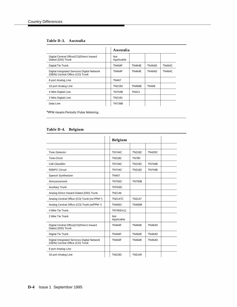
Country Differences
D-4 Issue 1 September 1995
*PPM means Periodic Pulse Metering.
Digital Central Office(CO)/Direct Inward Dialed (DID) Trunk
Not Applicable
Digital Tie Trunk TN464F TN464E TN464D TN464C
Digital Integrated Services Digital Network (ISDN) Central Office (CO) Trunk
TN464F TN464E TN464D TN464C
8 port Analog Line TN467
16 port Analog Line TN2183 TN468B TN468
4 Wire Digital Line TN754B TN413
2 Wire Digital Line TN2181
Data Line TN726B
Table D-4. Belgium
Belgium
Tone Detector TN744C TN2182 TN420C
Tone-Clock TN2182 TN780
Call Classifier TN744C TN2182 TN744B
R2MFC Circuit TN744C TN2182 TN744B
Speech Synthesizer TN457
Announcement TN750C TN750B
Auxiliary Trunk TN763D
Analog Direct Inward Dialed (DID) Trunk TN2146
Analog Central Office (CO) Trunk (no PPM *) TN2147C TN2147
Analog Central Office (CO) Trunk (w/PPM *) TN465C TN465B
4 Wire Tie Trunk TN760Dv11
2 Wire Tie Trunk Not Applicable
Digital Central Office(CO)/Direct Inward Dialed (DID) Trunk
TN464F TN464E TN464D
Digital Tie Trunk TN464F TN464E TN464D
Digital Integrated Services Digital Network (ISDN) Central Office (CO) Trunk
TN464F TN464E TN464D
8 port Analog Line
16 port Analog Line TN2183 TN2149
Table D-3. Australia
Australia

Country-Specific Hardware
Issue 1 September 1995 D-5
*PPM means Periodic Pulse Metering.
Table D-5. China
*PPM means Periodic Pulse Metering.
4 Wire Digital Line TN754B
2 Wire Digital Line TN2181 TN2136
Data Line TN726B
China
Tone Detector TN744C TN2182
Tone-Clock TN2182
Call Classifier TN744C TN2182 TN744B
R2MFC Circuit TN744C TN2182
Speech Synthesizer
Announcement TN750C TN750B
Auxiliary Trunk TN763D
Analog Direct Inward Dialed (DID) Trunk
Analog Central Office (CO) Trunk (no PPM *) TN465C
Analog Central Office (CO) Trunk (w/PPM*)
4 Wire Tie Trunk TN760D
2 Wire Tie Trunk
Digital Central Office/Direct Inward Dialed (DID) Trunk
TN464F
Digital Tie Trunk TN464F TN464E
Digital Integrated Services Digital Network (ISDN) Central Office (CO) Trunk
TN464F
8 port Analog Line
16 port Analog Line TN2183
4 Wire Digital Line TN754B
2 Wire Digital Line TN2181
Data Line TN726B
Table D-4. Belgium
Belgium

Country Differences
D-6 Issue 1 September 1995
*PPM means Periodic Pulse Metering.
Table D-6. Czech Republic, Slovakia, and Ecuador
Czech Republic& Slovakia Ecuador
Tone Detector TN744C TN2182 TN420C
Tone-Clock TN2182 TN780
Call Classifier TN744C TN2182 TN744B
R2MFC Circuit Not Applicable
Speech Synthesizer TN457
Announcement TN750C TN750B TN750C TN750B
Auxiliary Trunk TN763D TN763D
Analog Direct Inward Dialed (DID) Trunk TN753v17
Analog Central Office (CO) Trunk (no PPM *) TN747Bv12
Analog Central Office (CO) Trunk (w/PPM *) TN465C TN465B
4 Wire Tie Trunk TN760Dv11
2 Wire Tie Trunk
Digital Central Office (CO)/Direct Inward Dialed (DID) Trunk
TN464F TN464E
Digital Tie Trunk TN464F TN464E
Digital Integrated Services Digital Network (ISDN) Central Office (CO) Trunk
Not Applicable
8 port Analog Line
16 port Analog Line TN746B
4 Wire Digital Line TN754B TN754B
2 Wire Digital Line TN2136 TN2136
Data Line TN726B TN726B
Table D-7. France and Germany
France Germany
Tone Detector TN744C TN2182 TN744C TN2182 TN420C
Tone-Clock TN2182 TN2182 TN780
Call Classifier TN744C TN2182 TN744B TN744C TN2182 TN744B

Country-Specific Hardware
Issue 1 September 1995 D-7
NOTE:All systems in France require France-specific carriers provided by AT&T GBCS Barphone.
*PPM means Periodic Pulse Metering.
~ Become RON/TRON with modifications.
R2MFC Circuit Not Applicable
Not Applicable
Speech Synthesizer TN457 Not Applicable
Announcement TN750C TN750B TN750C TN750B
Auxiliary Trunk Not Applicable
TN763D
Analog Direct Inward Dialed (DID) Trunk
Not Applicable
TN2184
Analog Central Office (CO) Trunk (no PPM *)
Not Applicable
TN2147C
Analog Central Office (CO) Trunk (w/PPM *)
Not Applicable
TN2184
4 Wire Tie Trunk TN760D~ Not Applicable
2 Wire Tie Trunk Not Applicable
Not Applicable
Digital Central Office/ (CO) Direct Inward Dialed (DID) Trunk
TN464F Not Applicable
Digital Tie Trunk TN464F TN464E & F
Digital Integrated Services Digital Network (ISDN) Central Office Trunk
TN464F TN464F
8 port Analog Line Not Applicable
Not Applicable
16 port Analog Line TN2183 TN2183 TN2180
4 Wire Digital Line TN754B TN754B
2 Wire Digital Line TN2181 TN2181
Data Line TN726B TN726B
Ring Generator TN2202
Music on Hold 122A
Table D-7. France and Germany
France Germany

Country Differences
D-8 Issue 1 September 1995
*PPM means Periodic Pulse Metering.
Table D-8. Greece
Greece
Tone Detector TN744C TN2182 TN748D
Tone-Clock TN2182 TN780 TN756
Call Classifier TN744C TN2182 TN744B
R2MFC Circuit Not Applicable
Speech Synthesizer TN725B
Announcement TN750C TN750B TN750
Auxiliary Trunk TN763D TN763C
Analog Direct Inward Dialed Trunk (DID) TN753
Analog Central Office (CO) Trunk (no PPM *) TN747B
Analog Central Office (CO) Trunk (w/PPM *) TN465C TN465B TN465
4 Wire Tie Trunk TN760D
2 Wire Tie Trunk
Digital Central Office (CO)/Direct Inward Dialed (DID) Trunk
TN464F TN464E TN464D
Digital Tie Trunk TN464F TN464E TN464D TN464C
Digital Integrated Services Digital Network (ISDN) Central Office (CO) Trunk
Not Applicable
8 port Analog Line TN742
16 port Analog Line TN746B
4 Wire Digital Line TN754B
2 Wire Digital Line TN2181
Data Line TN726B
Table D-9. Hong Kong
Hong Kong
Tone Detector TN744C TN2182 TN748D
Tone-Clock TN2182 TN780 TN756
Call Classifier TN744C TN2182 TN744B
R2MFC Circuit Not Applicable
Speech Synthesizer TN725B
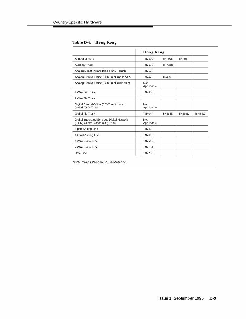
Country-Specific Hardware
Issue 1 September 1995 D-9
*PPM means Periodic Pulse Metering.
Announcement TN750C TN750B TN750
Auxiliary Trunk TN763D TN763C
Analog Direct Inward Dialed (DID) Trunk TN753
Analog Central Office (CO) Trunk (no PPM *) TN747B TN465
Analog Central Office (CO) Trunk (w/PPM *) Not Applicable
4 Wire Tie Trunk TN760D
2 Wire Tie Trunk
Digital Central Office (CO)/Direct Inward Dialed (DID) Trunk
Not Applicable
Digital Tie Trunk TN464F TN464E TN464D TN464C
Digital Integrated Services Digital Network (ISDN) Central Office (CO) Trunk
Not Applicable
8 port Analog Line TN742
16 port Analog Line TN746B
4 Wire Digital Line TN754B
2 Wire Digital Line TN2181
Data Line TN726B
Table D-9. Hong Kong
Hong Kong

Country Differences
D-10 Issue 1 September 1995
Table D-10. Hungary
*PPM means Periodic Pulse Metering.
Hungary
Tone Detector TN744C TN2182 TN748D TN748C
Tone-Clock TN2182 TN780 TN756
Call Classifier TN744C TN2182 TN744B
R2MFC Circuit TN744C TN2182 TN744B
Speech Synthesizer TN725B
Announcement TN750C TN750B
Auxiliary Trunk TN763D
Analog Direct Inward Dialed (DID) Trunk TN753
Analog Central Office (CO) Trunk (no PPM *) TN747B
Analog Central Office Trunk (w/PPM *) TN465C TN465B
4 Wire Tie Trunk TN760D
2 Wire Tie Trunk TN2140B
Digital Central Office (CO)/Direct Inward Dialed (DID) Trunk
TN464F TN464E TN464D
Digital Tie Trunk TN464F TN464E TN464D
Digital Integrated Services Digital Network (ISDN) Central Office (CO) Trunk
Not Applicable
8 port Analog Line TN742
16 port Analog Line TN746B
4 Wire Digital Line TN754B
2 Wire Digital Line TN2181 TN2136
Data Line TN726B
Table D-11. Italy
Italy
Tone Detector TN744C TN2182 TN420C
Tone-Clock TN2182 TN780 TN419B
Call Classifier TN744C TN2182 TN744B
R2MFC Circuit Not Applicable
Speech Synthesizer TN433
Announcement TN750C TN750B

Country-Specific Hardware
Issue 1 September 1995 D-11
*PPM means Periodic Pulse Metering.
Auxiliary Trunk TN763D TN417
Analog Direct Inward Dialed (DID) Trunk
TN2139
Analog Central Office (CO) Trunk (no PPM *)
Not Applicable
Analog Central Office (CO) Trunk (w/PPM *)
TN2138
4 Wire Tie Trunk TN2140B TN2140
2 Wire Tie Trunk TN497
Digital Central Office (CO)/Direct Inward Dialed (DID) Trunk
TN464F TN464E TN464D TN464C TN464B
Digital Tie Trunk TN464F TN464E TN464D TN464C TN464B
Digital Integrated Services Digital Network (ISDN) Central Office (CO) Trunk
Not Applicable
8 port Analog Line
16 port Analog Line TN2183 TN2135
4 Wire Digital Line TN754B TN413
2 Wire Digital Line TN2181 TN2136
Data Line TN726B
Table D-11. Italy
Italy

Country Differences
D-12 Issue 1 September 1995
Table D-12. Japan
*PPM means Periodic Pulse Metering.
Japan
Tone Detector TN744C TN2182 TN748D
Tone-Clock TN2182 TN780 TN756
Call Classifier TN744C TN2182 TN744B
R2MFC Circuit Not Applicable
Speech Synthesizer TN725B
Announcement TN750C TN750B TN750
Auxiliary Trunk TN763D TN763C
Analog Direct Inward Dialed (DID) Trunk
TN429
Analog Central Office (CO) Trunk (no PPM *)
TN429 TN465
Analog Central Office (CO) Trunk (w/PPM *)
Not Applicable
4 Wire Tie Trunk TN760D
2 Wire Tie Trunk TN439
Digital Central Office (CO)/Direct Inward Dialed (DID) Trunk
TN464F TN464E TN464D TN464C TN767
Digital Tie Trunk TN464F TN464E TN464D TN464C TN767
Digital Integrated Services Digital Network (ISDN) Central Office Trunk
TN464F TN464E TN464D TN464C
8 port Analog Line TN742
16 port Analog Line TN746B TN479
4 Wire Digital Line TN754B
2 Wire Digital Line TN2181
Data Line TN726B
Table D-13. Mexico
Mexico
Tone Detector TN744C TN2182 TN748D
Tone-Clock TN2182 TN780 TN756
Call Classifier TN744C TN2182 TN744B
R2MFC Circuit TN744C TN2182 TN744B
Speech Synthesizer TN725B

Country-Specific Hardware
Issue 1 September 1995 D-13
*PPM means Periodic Pulse Metering.
Announcement TN750C TN750B TN750
Auxiliary Trunk TN763D TN763C
Analog Direct Inward Dialed Trunk (DID) Not Applicable
Analog Central Office (CO) Trunk (no PPM *) TN747B
Analog Central Office (CO) Trunk (w/PPM *) TN465C TN465B
4 Wire Tie Trunk TN760D
2 Wire Tie Trunk
Digital Central Office (CO)/Direct Inward Dialed (DID) Trunk
TN464F
Digital Tie Trunk TN464F TN464E TN464D TN464C
Digital Integrated Services Digital Network (ISDN) Central Office (CO) Trunk
TN464F
8 port Analog Line TN742
16 port Analog Line TN746B
4 Wire Digital Line TN754B
2 Wire Digital Line
Data Line TN726B
Table D-14. Netherlands
Netherlands
Tone Detector TN744C TN2182 TN420C
Tone-Clock TN2182 TN780
Call Classifier TN744C TN2182 TN744B
R2MFC Circuit Not Applicable
Speech Synthesizer TN457
Announcement TN750C TN750B
Auxiliary Trunk TN763D
Analog Direct Inward Dialed (DID) Trunk TN2146
Analog Central Office (CO) Trunk (no PPM *) TN2147C
Analog Central Office (CO) Trunk (w/PPM *) Not Applicable
4 Wire Tie Trunk TN760Dv11
2 Wire Tie Trunk
Table D-13. Mexico
Mexico

Country Differences
D-14 Issue 1 September 1995
*PPM means Periodic Pulse Metering.
Digital Central Office (CO)/Direct Inward Dialed (DID) Trunk
TN464F TN464E TN464D
Digital Tie Trunk TN464F TN464E TN464D
Digital Integrated Services Digital Network (ISDN) Central Office (CO) Trunk
TN464F TN464E TN464D
8 port Analog Line
16 port Analog Line TN2183 TN2144
4 Wire Digital Line TN754B
2 Wire Digital Line TN2136
Data Line TN726B
Table D-15. Poland and Russia
Poland Russia
Tone Detector TN744C TN2182 TN748D TN748C TN744C TN420C
Tone-Clock TN2182 TN780 TN756 TN2182 TN780
Call Classifier TN744C TN2182 TN744B
R2MFC Circuit TN744C TN2182 TN744B TN744C TN2182 TN744Bv2
Speech Synthesizer TN725B TN457
Announcement TN750C TN750B TN750C TN750B
Auxiliary Trunk TN763D TN763D
Analog Direct Inward Dialed (DID) Trunk
TN753 TN753v17 TN2199
Analog Central Office (CO) Trunk (no PPM *)
TN747B TN747Bv12 TN2199
Analog Central Office (CO) Trunk (w/PPM *)
TN465C TN465B TN465
4 Wire Tie Trunk TN760D TN760Dv11
2 Wire Tie Trunk
Digital Central Office (CO)/Direct Inward Dialed (DID) Trunk
TN464F
Digital Tie Trunk TN464F TN464E TN464D TN464F
Digital Integrated Services Digital Network (ISDN) Central Office (CO) Trunk
Not Applicable
Not Applicable
8 port Analog Line TN742
16 port Analog Line TN746B TN746B
Table D-14. Netherlands
Netherlands

Country-Specific Hardware
Issue 1 September 1995 D-15
*PPM means Periodic Pulse Metering.
*PPM means Periodic Pulse Metering.
4 Wire Digital Line TN754B TN754B
2 Wire Digital Line TN2181 TN2136 TN2181 TN2136
Data Line TN726B TN726B
Table D-16. Saudi Arabia
Saudi Arabia
Tone Detector TN744C TN2182 TN748D
Tone-Clock TN2182 TN780 TN756
Call Classifier TN744C TN2182 TN744B
R2MFC Circuit TN744C TN2182 TN744B
Speech Synthesizer TN725B
Announcement TN750C TN750B
Auxiliary Trunk TN763D TN763C
Analog Direct Inward Dialed (DID) Trunk TN753
Analog Central Office (CO) Trunk (no PPM *)
TN747B
Analog Central Office (CO) Trunk (w/PPM *)
4 Wire Tie Trunk TN760D
2 Wire Tie Trunk
Digital Central Office (CO)/Direct Inward Dialed (DID) Trunk
TN464F
Digital Tie Trunk TN464F TN464E TN464D TN464C TN464B
Digital Integrated Services Digital Network (ISDN) Central Office (CO) Trunk
TN464F
8 port Analog Line TN742
16 port Analog Line TN746B
4 Wire Digital Line TN754B
2 Wire Digital Line TN2181
Data Line TN726B
Table D-15. Poland and Russia
Poland Russia

Country Differences
D-16 Issue 1 September 1995
Table D-17. Singapore
*PPM means Periodic Pulse Metering.
Singapore
Tone Detector TN744C TN2182 TN748D
Tone-Clock TN2182 TN780 TN756
Call Classifier TN744C TN2182 TN744B
R2MFC Circuit TN744C TN2182 TN744B
Speech Synthesizer TN725B
Announcement TN750C TN750B TN750
Auxiliary Trunk TN763D TN763C
Analog Direct Inward Dialed (DID) Trunk TN753
Analog Central Office (CO) Trunk (no PPM *)
TN747B
Analog Central Office (CO) Trunk (w/PPM *)
4 Wire Tie Trunk TN760D
2 Wire Tie Trunk
Digital Central Office (CO)/Direct Inward Dialed (DID) Trunk
TN464F
Digital Tie Trunk TN464F TN464E TN464D TN464C
Digital Integrated Services Digital Network (ISDN) Central Office (CO) Trunk
TN464F TN464E TN464D TN464C
8 port Analog Line TN742
16 port Analog Line TN746B
4 Wire Digital Line TN754B
2 Wire Digital Line
Data Line TN726B
Table D-18. Spain and Taiwan
Spain Taiwan
Tone Detector TN744C TN2182 TN420C TN744C TN2182 TN748D
Tone-Clock TN2182 TN780 TN2182 TN780 TN756
Call Classifier TN744C TN2182 TN744B
R2MFC Circuit TN744C TN2182 TN744Bv2 Not Applicable

Country-Specific Hardware
Issue 1 September 1995 D-17
*PPM means Periodic Pulse Metering.
Speech Synthesizer
TN457 TN725B
Announcement TN750C TN750B TN750C TN750B
Auxiliary Trunk TN763D TN763D TN763C
Analog Direct Inward Dialed (DID) Trunk
Not Applicable
TN753
Analog Central Office (CO) Trunk (no PPM *)
TN2147C TN747B
Analog Central Office (CO) Trunk (w/PPM *)
TN465C
4 Wire Tie Trunk Not Applicable
TN760D
2 Wire Tie Trunk Not Applicable
Digital Central Office (CO)/Direct Inward Dialed (DID) Trunk
TN464F TN464E
Digital Tie Trunk TN464F TN464F TN464E TN464D TN464C TN767
Digital Integrated Services Digital Network (ISDN) Central Office (CO) Trunk
TN464F TN464E Not Applicable
8 port Analog Line
TN742
16 port Analog Line
TN2183 TN2180 TN746B
4 Wire Digital Line
TN754B TN754B
2 Wire Digital Line
TN2181 TN2181
Data Line TN726B TN726B
Table D-18. Spain and Taiwan
Spain Taiwan

Country Differences
D-18 Issue 1 September 1995
*PPM means Periodic Pulse Metering.
Table D-19. United Kingdom
United Kingdom
Tone Detector TN744C TN2182 TN420C TN420B
Tone-Clock TN2182 TN780 TN419B
Call Classifier TN744C TN2182 TN744B
R2MFC Circuit Not Applicable
Speech Synthesizer TN457
Announcement TN750C TN750B
Auxiliary Trunk TN763D TN417
Analog Direct Inward Dialed (DID) Trunk TN459B TN459
Analog Central Office (CO) Trunk (no PPM *) TN2147C TN2147
Analog Central Office (CO) Trunk (w/PPM *) TN447
4 Wire Tie Trunk TN458
2 Wire Tie Trunk
Digital Central Office (CO)/Direct Inward Dialed (DID) Trunk
TN464F TN464E TN464D
Digital Tie Trunk TN464F TN464E TN464D TN464C
Digital Integrated Services Digital Network (ISDN) Central Office (CO) Trunk
TN464F TN464E TN464D
8 port Analog Line TN467
16 port Analog Line TN2183 TN468B TN468
4 Wire Digital Line TN754B TN413
2 Wire Digital Line TN2181
Data Line TN726B

Country-Specific Hardware
Issue 1 September 1995 D-19
Table D-20. Venezuela
*PPM means Periodic Pulse Metering.
Venezuela
Tone Detector TN744C TN2182 TN748D
Tone-Clock TN2182 TN780 TN756
Call Classifier TN744C TN2182 TN744B
R2MFC Circuit TN744C TN2182 TN744B
Speech Synthesizer TN725B
Announcement TN750C TN750B TN750
Auxiliary Trunk TN763D TN763C
Analog Direct Inward Dialed (DID) Trunk TN753
Analog Central Office (CO) Trunk (no PPM *) TN747B
Analog Central Office (CO) Trunk (w/PPM *) TN465C TN465B
4 Wire Tie Trunk TN760D
2 Wire Tie Trunk TN439
Digital Central Office (CO)/Direct Inward Dialed (DID) Trunk
Not Applicable
Digital Tie Trunk TN464F TN464E TN464D TN464C
Digital Integrated Services Digital Network (ISDN) Central Office (CO) Trunk
Not Applicable
8 port Analog Line TN742
16 port Analog Line TN746B
4 Wire Digital Line TN754B TN413
2 Wire Digital Line TN2181
Data Line TN726B

September 1995 Issue 1 E-1
EInstalling the 9400-Series Telephones
Installing the 9400-Series Telephones
The following figures provide the basic information to install the 9400-series telephones.
! CAUTION:When this product is located in a separate building from the DEFINITY Communications System, a line current protector MUST be installed at the entry/exit points of all buildings through which the line passes. However, there is a difference between 4-wire and 2-wire installations.
The following are the ONLY acceptable devices for use in a 4-wire installation (note that two protectors are needed at each installation point):
■ AT&T 4-type protectors
■ ITW LINX™ LP-type protectors
For 2-wire installations, the following is recommended (only one protector is needed at each installation point):
■ AT&T 4-type protectors
■ ITW LINX™ LP-type protectors
However, if the above two protectors are not used, the following is acceptable in a 2-wire installation:
■ AT&T 3BIC (Carbon block) or AT&T 3BEW (gas tube) protectors

Installing the 9400-Series Telephones
E-2 September 1995 Issue 1
NOTE:The 3BIC and 3BEW protectors can be used only for 2-wire installations. They cannot be used for 4-wire installations.
These telephones are not for residential use. They are for business systems applications only. Use in a residential environment could result in an electrical short circuit when the telephone wiring is set up to provide other applications, for example, for appliance control or power transformers. The AC power used in these applications may create a safety hazard by placing a direct short circuit across the telephone wiring.
Wiring Information
The 9403 and the 9434 telephones work in both 2-wire and 4-wire configurations. The 9410 telephone works only in the 2-wire digital communications protocol (DCP) configuration. Wiring is also discussed in Chapter 9, "Install and Wire Telephones and Other Equipment".
Figure E-1 and Figure E-2 show an enlargement of a telephone 8-pin line jack in a 2-wire and a 4-wire configuration, respectively. Table E-1 below these figures describes the pins on this jack.
Figure E-1 shows power requirements in a 2-wire installation. Switch connections must be on pair 1 (Pins 4 and 5).
Figure E-1. A Telephone Line Jack in a 2-Wire Configuration
Figure E-2 shows power requirements in a 4-wire installation. Switch connections must be on pair 2 (Pins 1 and 2) and pair 3 (Pins 3 and 6).
1 2 3 4 5 6 7 8

Wiring Information
September 1995 Issue 1 E-3
Figure E-2. A Telephone Line Jack in a 4-Wire Configuration
NOTE:Regardless of configuration, all wiring between the switch and the wall jack must consist of twisted-pairs. Use the supplied line cord with the telephone, or use an AT&T approved equivalent. An 8-wire modular cord must be used for all 4-wire and 2-wire installations requiring auxiliary power for adjuncts such as a hands-free speaker/microphone.
Table E-1. Pinouts on 8-Pin Line Jack
Modular Wall Jack Wiring
Pin Pair Color Description
1 2 W-O 4-Wire Output
2 2 O-W 4-Wire Output
3 3 W-G 4-Wire Input
4 1 BL-W 2-Wire (Tip)
5 1 W-BL 2-Wire (Ring)
6 3 G-W 4-Wire Input
7 4 W-BR Adjunct Power -48V
8 4 BR-W Adjunct Power Common
1 2 3 4 5 6 7 8

Installing the 9400-Series Telephones
E-4 September 1995 Issue 1
NOTE:Do not change any settings on the telephone for 2-wire or 4-wire installations. The telephone is able to detect whether it is in a 2-wire or a 4-wire configuration.
Distance Limitations
The following are the maximum distances allowed between the system and the 9400-series telephones.
Table E-2. Maximum Distances between system and 9400-Series Telephones
22-gauge 24-gauge 26-gauge0.6 mm (Europe)
4-wire 1,500 meters
(5,000 feet)
1,500 meters
(5,000 feet)
1,200 meters
(4,000 feet)
1,500 meters
(5,000 feet)
2-wire 1,650 meters
(5,500 feet)
1,050 meters
(3,500 feet)
650 meters
(2,220 feet)
1,350 meters
(4,500 feet)
3
2
5
4
LINE
1
6
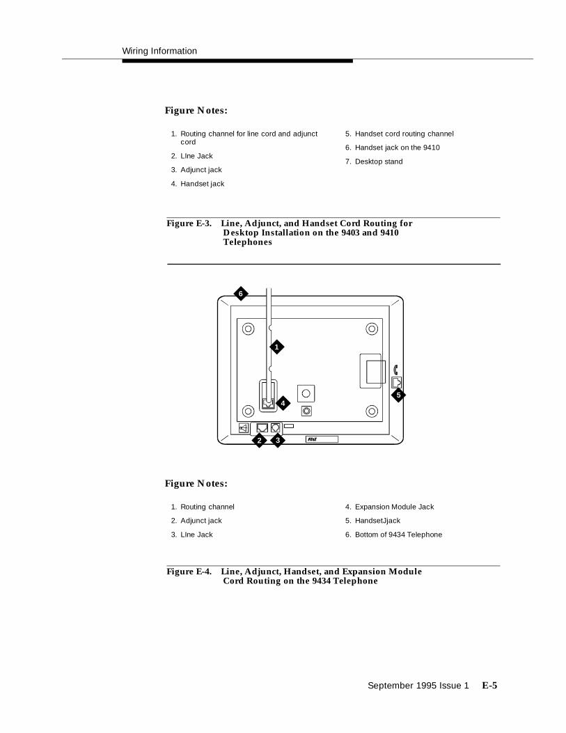
Wiring Information
September 1995 Issue 1 E-5
Figure E-3. Line, Adjunct, and Handset Cord Routing for Desktop Installation on the 9403 and 9410 Telephones
Figure E-4. Line, Adjunct, Handset, and Expansion Module Cord Routing on the 9434 Telephone
1. Routing channel for line cord and adjunct cord
2. LIne Jack
3. Adjunct jack
4. Handset jack
5. Handset cord routing channel
6. Handset jack on the 9410
7. Desktop stand
Figure Notes:
45
6
32
1
1. Routing channel
2. Adjunct jack
3. LIne Jack
4. Expansion Module Jack
5. HandsetJjack
6. Bottom of 9434 Telephone
Figure Notes:

Installing the 9400-Series Telephones
E-6 September 1995 Issue 1
Wall Mounting
Only the 9403 and the 9410 can be wall mounted, as shown below in Figure E-4, Figure E-5, Figure E-6, Figure E-7, and Figure E-8.
Figure Notes:
1. Hand Retainer in Place
2. Press to Release and Remove Handset Retainer
3. Rotate Handset 180 Degrees
4. Replace Handset Retainer
Figure E-5. Reversing the Handset Hook for Wall Mounting
3 4
1 2
180°

Wall Mounting
September 1995 Issue 1 E-7
Figure Notes:
1. Desktop stand
2. Desk mount tab slot
Figure E-6. Removing the Desktop Stand for Wall Mounting
2
1

Installing the 9400-Series Telephones
E-8 September 1995 Issue 1
Figure Notes:
1. Line cord routing channel for wall mount
2. Line jack
3. Handset jack
4. Handset cord routing channel
Figure E-7. Line Cord Routing for Wall Mount
2
3
1
4

Using the Test Feature
September 1995 Issue 1 E-9
Figure E-8. Placing the Telephone onto Wall Jack Mounting Studs
Using the Test Feature
When the telephone is initially powered up, the green light next to the TEST button flashes if the telephone is not (or not yet) able to communicate with the switch. The light changes to steady green when the switch link is operational. After a short period of time, the light turns off in order to conserve power.
NOTE:If the light next to TEST does not come on, the telephone is not receiving power from the switch.
The Test Feature
To test the lights and the display on your telephone:
5. While on-hook, press and hold down TEST.
■ Green light next to TEST goes on.
NOTE:If the green light next to TEST flashes rather than going on steadily, it means that the telephone is not able to communicate with the switch.

Installing the 9400-Series Telephones
E-10 September 1995 Issue 1
■ The button lights on your telephone go on (and, if the terminal has a display, all the display segments fill in):
— On the 9403, all the lights go on together.
— On the 9410, the lights go on in two groups, and the display fills in all the segments.
— On the 9434, the lights go on in four groups, and the display fills in all the segments.
6. Release TEST to end the test.
■ Lights return to pretest state.
■ Green light next to TEST goes off.
NOTE:You can test the tone ringer on your telephone by pressing either side of the volume control button when the handset is on-hook and the speaker is not in use.
Button Labels
The following buttons appear on the 9400-series telephones. The button labels in this table are provided in English and French.
Table E-3. Button Labels for 9400-Series Telephones.
English Button Labels French Button Labels
Volume
Shift/Feature 2nd F
Test Test
Mute Secret
Speaker
Transfer Trans
Conf Conf
Drop Lib
Hold Attente

September 1995 Issue 1 F-1
FWire Conversion Information
This appendix provides some wire conversion information that may be useful when following the installation instructions provided in this book.
Common Wire Colours
Table F-1 lists common wires types and colours for power (AC Mains):
AWG to SWG Conversion (Stranded Wire)
The following table provides conversion information from American Wire Gauge (AWG) to British (Imperial) Standard Wire Gauge (SWG). It also includes metric sizes.
Table F-1. Standard Wire Colours for Power (AC Mains)
Wire Type United States Europe
Neutral or Telecommunications Ground
White Blue
Hot Black Black or Brown
Ground Green, or Green with Yellow Stripe
Green with Yellow Stripe
Tip Green
Ring Red

Wire Conversion Information
F-2 September 1995 Issue 1
)
Table F-2. Stranded Wire Conversion (AWG to SWG to metric)
Square Millimeters
Number and Diameter of Strands Millimeters
Corresponding AWG
0.014 7 x 0.05 --
0.035 7 x 0.08 --
0.047 24 x 0.05 --
0.049 1 x 0.25 --
0.055 7 x 0.10 --
0.079 10 x 0.10 28
0.079 7 x 0.12 28
0.080 1 x 0.32 28
0.093 7 x 0.13 --
0.094 12 x 0.10 --
0.094 48 x 0.05 --
0.096 19 x 0.08 --
0.113 10 x 0.12 --
0.118 60 x 0.05 --
0.118 15 x 0.10 --
0.124 7 x 0.15 --
0.126 1 x 0.40 26
0.149 19 x 0.10 --
0.177 10 x 0.15 --
0.188 24 x 0.10 --
0.196 1 x 0.50 --
0.212 27 x 0.10 --
0.212 12 x 0.15 --
0.220 7 x 0.20 --
0.251 32 x 0.10 --
0.252 19 x 0.13 --
0.283 1 x 0.60 --
0.291 37 x 0.10 --
0.314 40 x 0.10 --
0.322 1 x 0.64 22
0.336 19 x 0.15 22
0.344 7 x 0.25 --
0.377 12 x 0.20 --

AWG to SWG Conversion (Stranded Wire)
September 1995 Issue 1 F-3
0.377 48 x 0.10 --
0.389 22 x 0.15 --
0.442 1 x 0.75 --
0.459 26 x 0.15 --
0.491 10 x 0.25 --
0.495 7 x 0.30 --
0.503 16 x 0.20 --
0.515 1 x 0.81 20
0.563 7 x 0.32 --
0.597 19 x 0.20 --
0.636 36 x 0.15 --
0.754 24 x 0.20 --
0.785 16 x 0.25 --
0.817 1 x 1.02 18
0.848 12 x 0.30 --
0.880 7 x 0.40 --
0.933 19 x 0.25 --
0.990 56 x 0.15 --
1.005 32 x 0.20 --
1.276 26 x 0.25 --
1.327 1 x 1.30 16
1.343 19 x 0.30 --
1.374 7 x 0.50 --
1.473 30 x 0.25 --
1.508 12 x 0.40 --
1.828 19 x 0.35 --
1.885 60 x 0.20 --
1.909 27 x 0.30 --
1.979 7 x 0.60 --
2.011 16 x 0.40 --
2.013 41 x 0.25 --
2.087 1 x 1.63 14
2.454 50 x 0.25 --
Table F-2. Stranded Wire Conversion (AWG to SWG to metric)
Square Millimeters
Number and Diameter of Strands Millimeters
Corresponding AWG

Wire Conversion Information
F-4 September 1995 Issue 1
Wire Gauge Comparison(Solid Conductor)
Table F-3 provides information for converting American Wire Gauge (AWG) to British Standard Wire Gauge (Imperial), in addition to metric wire gauge.
3.022 19 x 0.45 --
3.142 16 x 0.50 --
3.181 45 x 0.30 --
3.191 65 x 0.25 --
3.393 48 x 0.30 12
3.958 56 x 0.30 --
4.650 37 x 0.40 --
4.714 7 x 7 x 0.35 --
5.154 105 x 0.25 --
5.160 73 x 0.30 10
5.300 75 x 0.30 10
Table F-2. Stranded Wire Conversion (AWG to SWG to metric)
Square Millimeters
Number and Diameter of Strands Millimeters
Corresponding AWG

Wire Gauge Comparison (Solid Conductor)
September 1995 Issue 1 F-5
Table F-3. Solid Conductor Wire Gauge Comparison (AWG to SWG to metric)
Diameter(Mils)
Gauge Numbers(mm)
American Wire Gauge (AWG)
British Standard Wire Gauge (Imperial)
Metric Wire Gauge
460.1 11.68 4/0 -- --
432 11.0 -- 5/0 --
409.6 10.40 3/0 -- --
400 10.2 -- 4/0 --
393.7 10.0 -- -- 100
372 9.45 -- 3/0 --
364.8 9.266 2/0 -- --
354 9.00 -- -- 90
348 8.84 -- 2/0 --
324.9 8.252 1/0 -- --
324 8.23 -- 1/0 --
315 8.00 -- -- 80
300 7.62 -- 1 --
289.3 7.348 1 -- --
276 7.01 -- 2 --
276 7.00 -- -- 70
257.6 6.543 2 -- --
252 6.40 -- 3 --
236 6.00 -- -- 60
232 5.89 -- 4 --
229.4 5.827 3 -- --
212 5.38 -- 5 --
204.3 5.189 4 -- --
197 5.00 -- -- 50
192 4.88 -- 6 --
181.9 4.620 5 -- --
177.2 4.50 -- -- 45
176 4.47 -- 7 --
162.0 4.115 6 -- --
160 4.06 -- 8 --
157 4.00 -- -- 40
144.3 3.665 7 -- --
144 3.66 -- 9 --

Wire Conversion Information
F-6 September 1995 Issue 1
138 3.50 -- -- 35
128.5 3.264 8 -- --
128 3.25 -- 10 --
118 3.00 -- -- 30
116 2.95 -- 11 --
114.4 2.906 9 -- --
104 2.64 -- 12 --
101.9 2.588 10 -- --
98.4 2.50 -- -- 25
92 2.34 -- 13 --
90.7 2.30 11 -- --
80.8 2.05 12 -- --
80.0 2.03 -- 14 --
78.7 2.00 -- -- 20
72.0 1.83 13 15 --
70.9 1.80 -- -- 18
64.1 1.63 14 -- --
64 1.63 -- 16 --
63 1.60 -- -- 16
57.1 1.45 15 -- --
56 1.42 -- 17 --
55.1 1.40 -- -- 14
50.8 1.29 16 -- --
48 1.22 -- 18 --
47.2 1.20 -- -- 12
45.3 1.15 17 -- --
40.3 1.02 18 -- --
40 1.02 -- 19 --
39.4 1.00 -- -- 10
36 0.914 -- 20 --
35.9 0.912 19 -- --
35.4 0.90 -- -- 9.0
32.0 0.813 20 21 --
31.5 0.800 -- -- 8.0
28.5 0.724 21 -- --
Table F-3. Solid Conductor Wire Gauge Comparison (AWG to SWG to metric)
Diameter(Mils)
Gauge Numbers(mm)
American Wire Gauge (AWG)
British Standard Wire Gauge (Imperial)
Metric Wire Gauge

Wire Gauge Comparison (Solid Conductor)
September 1995 Issue 1 F-7
28 0.711 -- 22 --
27.6 0.70 -- -- 7.0
25.3 0.643 22 -- --
24 0.610 -- 23 --
23.6 0.60 -- -- 6.0
22.6 0.574 23 -- --
22 0.559 -- 24 --
20.1 0.511 24 -- --
20 0.508 -- 25 --
19.7 0.50 -- -- 5.0
18 0.457 -- 26 --
17.9 0.455 25 -- --
17.7 0.45 -- -- 4.5
16.4 0.417 -- 27 --
15.9 0.404 26 -- --
Table F-3. Solid Conductor Wire Gauge Comparison (AWG to SWG to metric)
Diameter(Mils)
Gauge Numbers(mm)
American Wire Gauge (AWG)
British Standard Wire Gauge (Imperial)
Metric Wire Gauge

September 1995 Issue 1 G-1
GElectrical Code Equivalencies
This appendix lists electrical code information that applies to countries outside of North America.
North American Electrical Code
In North America, the standard electrical code that must be followed is called the National Electrical Code (NEC). When installing DEFINITY System G3, you must determine the equivalent code in your country.
International Electrical Codes
The following chart lists the regulatory electrical codes in applicable countries:

Electrical Code Equivalencies
G-2 September 1995 Issue 1
:
Table G-1. International Electrical Codes
Country Electrical Code/Regulations
Australia
Belgium
China
France
Germany DIN/VDE Bestimmungen
Italy
Japan
Macedonia
Malaysia
Netherlands
Spain
Thailand
United Kingdom
United States National Electrical Code (NEC)

September 1995 Issue 1 H-1
HOption Switch Settings
Some of the interface units used between the single-carrier and multi-carrier cabinets and other types of equipment require specific option switch settings for each application. This section lists the option switch settings required for modular processor data modules, modular trunk data modules, modems, printers, etc., when these units are used with the switch. Only the option switch settings for use with single-carrier or multi-carrier cabinets are shown. Refer to the User Guide on each type of equipment for information on how to locate and set the option switches.
Distributed Communications System (DCS) Option Settings for G3i Systems
The distributed communications system (DCS) is sometimes connected to the switch through the processor interface circuit pack. The first circuit on the processor interface can be connected directly to the distributed communications system (DCS) through the PROCESSOR INTERFACE connector on the rear of the control carrier. Any of the remaining three circuits on the processor interface used to support the distributed communications system (DCS) must be

Option Switch Settings
H-2 September 1995 Issue 1
connected through a modular processor data module serving as the interface link. The option settings for the modular processor data module (MPDM) in this application are shown in Table H-1.
Modem Pooling (Combined) Option Settings
Combined Modem Pooling requires option switch settings on different modems and modular trunk data modules. The following paragraphs describe the option settings for each application.
103JR Modem Option Settings
When the 103JR modem is used with a modular trunk data module, set the options on the modular trunk data module as shown in Table H-2. Options for the 103JR modem are shown in Table H-3. When used for modem pooling, all factory-furnished options on the modem are used.
Table H-1. Option Switch Settings on the Modular Processor Data Module for the Distributed Communications System
Switch Setting
9600 BAUD ON
SYNC ON
INT ON
KYBD ON
AANS ON
All Others OFF
Table H-2. Option Switch Settings on the Modular Trunk Data Module Used With 103JR Modem
Switch Setting
300 baud ON
SW ON
SIGLS ON
CN25 ON
All Others OFF

103JR Modem Option Settings
September 1995 Issue 1 H-3
Table H-3. Option Switch Settings for 103JR Modem
Feature Option
Switch Setting S2 Switch on CM1 Contact Setting
1 2 3 4 5 6 7
Receive Space Disconnect
YES V* -- -- O -- -- -- --
Send Space Disconnect
YES T* X -- -- -- -- -- --
Loss of Carrier Disconnect
YES S* -- -- -- O -- -- --
Country Code (CC) Indication
EARLY ZD* -- -- -- -- -- -- O
CB and CF Indications
COMMON A* -- X -- -- -- -- --
Country Code (CC) Indication for Analog Loop
ON ZF* -- -- -- -- O -- --
Automatic Answer YES ZH* -- -- -- -- -- O --
S3 Switch on CP1 Contact Setting
1 2 3
Fail Safe State of CN Circuit
OFF J* O
Common Ringer NO ZA* O
Tip-Ring Make Busy
NO E* O
Common Grounds YES Q* Close S1 Screw Switch on Data Mounting
* = Factory Furnished
X = Contact closed
O = Contact open
-- = Contact not applicable
Continued on next page
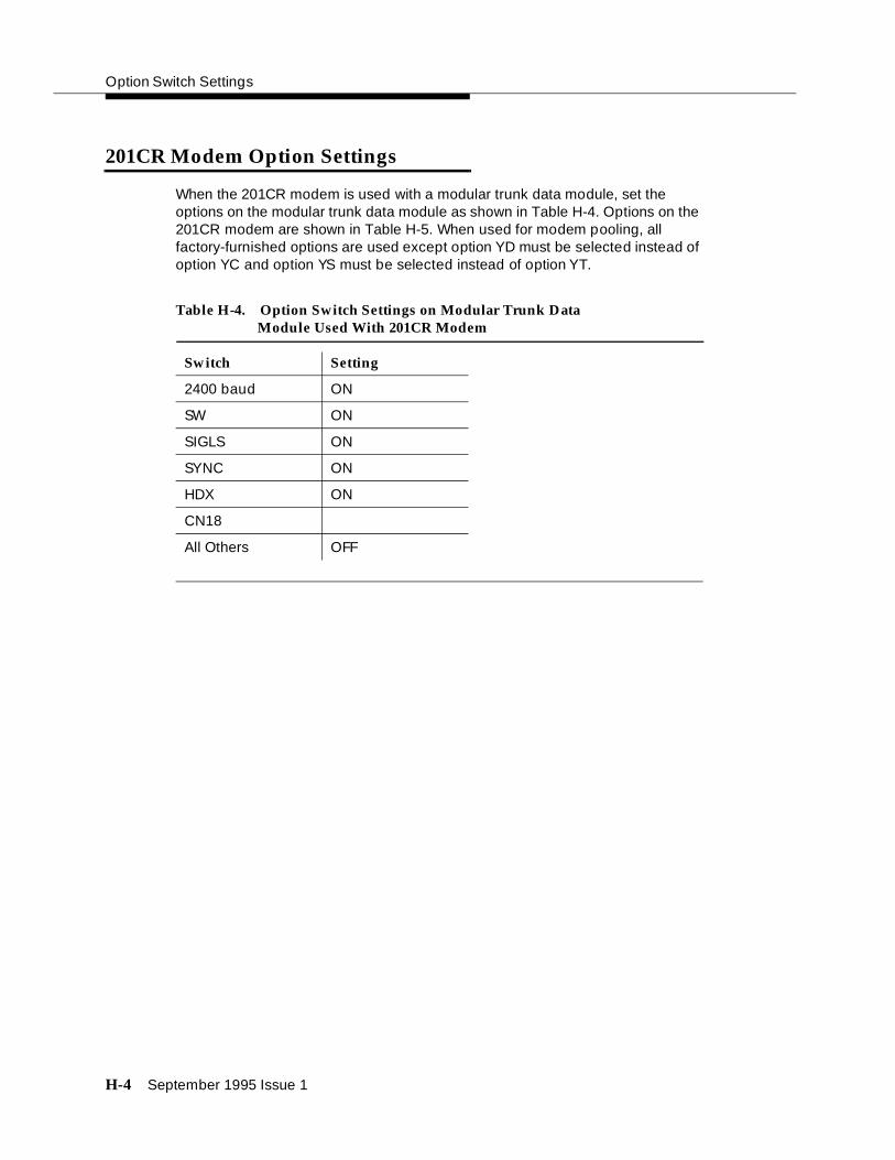
Option Switch Settings
H-4 September 1995 Issue 1
201CR Modem Option Settings
When the 201CR modem is used with a modular trunk data module, set the options on the modular trunk data module as shown in Table H-4. Options on the 201CR modem are shown in Table H-5. When used for modem pooling, all factory-furnished options are used except option YD must be selected instead of option YC and option YS must be selected instead of option YT.
Table H-4. Option Switch Settings on Modular Trunk Data Module Used With 201CR Modem
Switch Setting
2400 baud ON
SW ON
SIGLS ON
SYNC ON
HDX ON
CN18
All Others OFF

201CR Modem Option Settings
September 1995 Issue 1 H-5
Table H-5. Options Switch Settings for 201 CR Modem
Option Line Control Board (TP1B)
Description DesignationStrap In
(Vertical)Strap Out
(Horizontal)
Transmit Line Signal Level
-4 dBm ZE* 1,2,4,8
Switch Setting DigitalBoard(JB4B)1 2 3 4 5 6 7 8
Transmitter Timing
External YD O
Automatic Answer
DTR-Controlled Only
YF* X
Grounding Signal Ground Connected to Frame Ground
YK* Install E1-E2
Function of Electronic Industries AssociationInterface Pin 18
Initiates Analog Receiver
YS X Install E3-E4
ContinuousReceiverBit Clock
Out YP* X
Satellite In YQ* X
* = Factory furnished
X =Closed
O =Open
Continued on next page

Option Switch Settings
H-6 September 1995 Issue 1
202SR Modem Option Settings
When the 202SR modem is used with a modular trunk data module, set the options on the modular trunk data module as shown in Table H-6. Options on the 202SR modem are shown in Table H-7. When used for modem pooling, all factory-furnished options are used except option YI must be selected instead of option YJ.
Table H-6. Option Switch Settings on Modular Trunk Data Module Used With 202SR Modem
Switch Setting
1200 baud ON
SW ON
SIGLS ON
HDX ON
All Others OFF

202SR Modem Option Settings
September 1995 Issue 1 H-7
Table H-7. Option Switch Settings for 202SR Modem
S4 Switch Contact Setting On Transmitter-Receiver
Option OutputleveldBm
Without Reverse Channel With Reverse Channel
Description Designation 1 2 3 4 5 6 7 1 2 3 4 5 6 7
TransmitLine SignalLevel
ZO* -4 X X X X X X X X X X X X X X
Soft Turnoff Squelch
S2 Switch Contact Setting On Transmitter-Receiver
1 2 3 4 5 6 7 8 9 0
Soft Turnoff and Squelch Intervals
R* 24 milli-
seconds
156 milliseconds
-- X X -- -- -- -- O -- O
Fast Carrier Detection
N* Out (23 milliseconds) -- -- -- -- -- -- X -- -- --
Clear to Send Interval
G* 180 milliseconds -- -- -- X X -- -- -- -- --
Automatic Answer
B* In X -- -- -- -- -- -- -- -- --
Local Copy on Primary Channel
ZB* Out -- -- -- -- -- X -- -- -- --
Condition of Country Code (Data Set Ready) During Analog Loopback
YI On -- -- -- -- -- -- -- -- X --
S3 Switch Contact Setting
1 2 3 4 5 6
Reverse Channel
ZD* Out X X -- -- -- --
X =Contact closed
-- = Contact not applicable
O = Contact open
* = Factory furnished
Continued on next page

Option Switch Settings
H-8 September 1995 Issue 1
Option S3 Switch Contact Setting
Description Designation 1 2 3 4 5 6
Transmit Only
YH* Out -- -- O -- -- --
Echo Suppressor Enable
YR* Out -- -- -- X -- --
Carrier Controlled Turnaround
YS* In -- -- -- -- -- O
Early Country Code (Data Set Ready) Indication
YV* Out -- -- -- -- X --
Grounding Option
Screw Switch Setting On Interface Circuit
ZG* Signal Ground Connected to Frame Ground
Screw Switch S1 Closed on Data Mounting
X =Contact closed
-- = Contact not applicable
O = Contact open
* = Factory furnished
Table H-7. Option Switch Settings for 202SR Modem — Continued
Continued on next page

208BR Modem Option Settings
September 1995 Issue 1 H-9
208BR Modem Option Settings
When the 208BR modem is used with a modular trunk data module, set the options on the modular trunk data module as shown in Table H-8. Options for the 208BR modem are shown in Table H-9. When used for modem pooling, all factory-furnished options are used except option YD must be selected instead of option YC, and option YM must be selected instead of option YN.
Table H-8. Option Switch Settings on Modular Trunk Data Module Used With 208BR Modem
Switch Setting
4800 baud ON
SW ON
SIGLS ON
SYNC ON
HDX ON
All Others OFF

Option Switch Settings
H-10 September 1995 Issue 1
Table H-9. Option Switch Settings for 208BR Modem
Option Switch
Description Designation
OutputLeveldBm S1A S1B S1C S2A
Transmit Line Signal Level
ZE* -4 DOWN UP DOWN UP
Switch Option Strap Position
Compromise Equalizer (4-dB Slope)
WU* S2B Up
S2C Up
Data Set Ready (DSR) on for Analog Loop Mode
YM S3A Up
Automatic Answer YP* S3B Down
Transmitter Externally Timed
YD S3C Up
S4A** Up
Down*
S4B** Up
Down*
RS-CS Interval of 50 milliseconds
(Customer Switch)
50 In
RS-CS Interval of 150 milliseconds
Out
* Factory installed ** Down position must be selected
Continued on next page

Asynchronous 212AR Modem Option Settings
September 1995 Issue 1 H-11
Asynchronous 212AR Modem Option Settings
When the asynchronous 212AR modem is used with a modular trunk data module, set the options on the modular trunk data module as shown in Table H-10. Options on the asynchronous 212AR modem are shown in Table H-11. When used for modem pooling, all factory-furnished options are used with the following exceptions:
■ Select option XJ instead of option XK.
■ Select option YE instead of option YF.
■ Select option XL instead of option XM.
■ Select option YQ instead of option YR.
■ Select option XR instead of option XO.
Table H-10. Option Switch Settings on Modular Trunk Data Module (MTDM) Used With 212AR Modem
Switch Setting
300 baud ON
1200 baud ON
SW ON
SIGLS ON
CI12 ON
TM25 ON
CN18 ON
CH23 ON
RL21 ON
All Others OFF

Option Switch Settings
H-12 September 1995 Issue 1
Table H-11. Option Switch Settings for Asynchronous 212AR Modem
Switch Setting
Feature Option Description
S1 Switch Controls
1 2 3
Tip, Ring, Make Busy
E* OUT O -- --
Country Code (CC) Indication for Analog Loop
ZF* ON -- -- X
Switch Contacts
S2 S5
1 2 3 4 5 6 7 8 9 1 2
Speed Control XJ INTERFACE O -- -- -- -- -- -- -- --
Interface-Controlled Make Busy/ Analog Loop-CN
YE IN -- O -- -- -- -- -- -- --
Transmitter Timing
YC* INTERNAL -- -- O O -- -- -- -- --
1200-bps Operation
YG* ASYNCHRONOUS/START-STOP
-- -- -- -- O -- -- -- -- O O
Character Length (Use With YG)
YJ* 10-BIT -- -- -- -- -- X -- -- --
Receiver Responds to Digital Loop
YK* IN -- -- -- -- -- -- O -- --
Interface Controlled Remote Digital Loop
XL IN -- -- -- -- -- -- -- X --
S3 Switch Contacts
1 2 3 4 5 6 7 8
Loss of Carrier Disconnect
S* IN X -- -- -- -- -- -- --
Receive Space Disconnect
V* IN -- X -- -- -- -- -- --
* = Factory furnished X = Contact closed
O = Contact open -- = Contact not applicable
Continued on next page

Asynchronous 212AR Modem Option Settings
September 1995 Issue 1 H-13
Feature Option Description
S3 Switch Contacts
1 2 3 4 5 6 7 8
CB and CF Indications
A* COMMON -- -- X -- -- -- -- --
Send Space Disconnect
T* IN -- -- -- X -- -- -- --
Automatic Answer
ZH* IN -- -- -- -- X -- -- --
Answer Mode Indication
W* CE OFF -- -- -- -- -- O -- --
Speed Mode YP* DUAL -- -- -- -- -- -- O --
Interface Speed Indication Clock Input
YQ IN -- -- -- -- -- -- -- X
Strapping Options
CN and Test Mode Assignments
XR CN 18, TM 25 INSTALL E2 - E3, E4 - E5
Signal Ground to Frame Connection
Q* IN S1 CLOSED
* = Factory furnished X = Contact closed
O = Contact open -- = Contact not applicable
Table H-11. Option Switch Settings for Asynchronous 212AR Modem — Continued
Switch Setting
Continued on next page

Option Switch Settings
H-14 September 1995 Issue 1
Synchronous 212AR Modem Option Settings
When the synchronous 212AR modem is used with a modular trunk data module (MTDM), set the options on the modular trunk data module (MTDM) as shown in Table H-10. Options on the synchronous 212AR modem are shown in Table H-12. When used for modem pooling, all factory-furnished options are used with the following exceptions:
■ Select option YH instead of option YG.
■ Select option YO instead of option YP.
■ Select option YD instead of option YC
■ Select option YE instead of option YF.
■ Select option XL instead of option XM.
■ Select option XR instead of option XO.

Synchronous 212AR Modem Option Settings
September 1995 Issue 1 H-15
Table H-12. Option Switch Settings for Synchronous 212AR Modem
Switch Setting
Feature Option Description
S1 Switch Contacts
1 2 3
Tip, Ring, Make Busy
E* OUT O -- --
Country Code (CC) Indication for Analog Loop
ZF* ON -- -- X
Switch Contacts
S2 S5
1 2 3 4 5 6 7 8 9 1 2
Speed Control XK* HS BUTTON X -- -- -- -- -- -- -- --
Interface-Controlled Make Busy/ Analog Loop-CN
YE IN -- O -- -- -- -- -- -- --
Transmitter Timing
YD EXTERNAL -- -- O X -- -- -- -- --
1200-bps Operation
YH* SYNCHRONOUS -- -- -- -- X -- -- -- -- X X
Character Length (Use With YG)
YJ* 10-BIT -- -- -- -- -- X -- -- --
Receiver Responds to Digital Loop
YK* IN -- -- -- -- -- -- O -- --
Interface Controlled Remote Digital Loop
XL IN -- -- -- -- -- -- -- X --
S3 Switch Settings
1 2 3 4 5 6 7 8
Loss of Carrier Disconnect
S* IN X -- -- -- -- -- -- --
Receive Space Disconnect
V* IN -- X -- -- -- -- -- --
* = Factory furnished X = Contact closed
O = Contact open -- = Contact not applicable
Continued on next page

Option Switch Settings
H-16 September 1995 Issue 1
Feature Option Description
S3 Switch Contacts
1 2 3 4 5 6 7 8
CB and CF Indications
A* COMMON -- -- X -- -- -- -- --
Send Space Disconnect
T* IN -- -- -- X -- -- -- --
Automatic Answer
ZH* IN -- -- -- -- X -- -- --
Answer Mode Indication
W* CE OFF -- -- -- -- -- O -- --
Speed Mode YO HUGH -- -- -- -- -- -- X --
Interface Speed Indication Clock Input (CI)
YR* OUT -- -- -- -- -- -- -- O
Strapping Options
CN and Test Mode (TM) Assignments
XR CN 18, TM 25 INSTALL E2 - E3, E4 - E5
Signal Ground to Frame Connection
Q* IN S1 CLOSED
* = Factory furnished X = Contact closed
O = Contact open -- = Contact not applicable
Table H-12. Option Switch Settings for Synchronous 212AR Modem — Continued
Switch Setting
Continued on next page

Asynchronous 2224A Modem Option Settings
September 1995 Issue 1 H-17
Asynchronous 2224A Modem Option Settings
When the asynchronous 2224A modem is used with a modular trunk data module (MTDM), set the options on the modular trunk data module (MTDM) as shown in Table H-13. The asynchronous 2224A modem can also be used for modem pooling.
All factory-furnished options should be set on the 2224A modem with the following exceptions:
■ Interface speed indication—TRIPLE
■ Interface speed selection—TRIPLE
■ Analog (AL) and Test Mode interface assignments—AL-18 and TM-25
■ Interface control remote digital loopback—IN
Table H-13. Option Switch Settings on Modular Trunk Data Module (MTDM) Used with Asynchronous 2224A Modem
Switch Setting
300 baud ON
1200 baud ON
2400 baud ON
SW ON
SIGLS ON
CI12 ON
TM25 ON
CN18 ON
CH23 ON
RL21 ON
CI13 ON
CH19 ON
All Others OFF

Option Switch Settings
H-18 September 1995 Issue 1
Synchronous 2224A Modem Option Settings
When the synchronous 2224A modem is used with a modular trunk data module, set the options on the modular trunk data module as shown in Table H-14. All factory-furnished options should be set on the 2224A modem with the following exceptions:
■ Interface speed indication—DUAL-1200/2400
■ Interface speed selection—DUAL-1200/2400
■ Analog (AL) and Test Mode interface assignments—AL-18 and TM-25
■ Interface control remote digital loopback—IN
■ 1200/2400 bps operation—SYNC
■ Transmitter timing—EXT
Table H-14. Option Switch Settings on Modular Trunk Data Module (MTDM) Used with Synchronous 2224A Modem
Switch Setting
1200 baud ON
2400 baud ON
SW ON
SIGLS ON
CI12 ON
TM25 ON
CN18 ON
CH23 ON
RL21 ON
SYNC ON
CH19 ON
All Others OFF

7400A Option Settings
September 1995 Issue 1 H-19
7400A Option Settings
Determine if the 7400A will be interfacing with D-lead modems or attention control modems. Use Table H-15 to set the options to interface with D lead modems and Table H-16 to set the options to interface with attention control modems.
Notes:
1. Set speed to match remote modem. At least one speed must be set to ON.
2. Set to match remote modem.
Table H-15. 7400A Options for D Lead Modems
Set Option Display Option Desired Setting
Set 300 Speed? 300 Note 1
Set 1200 Speed? 1200 Note 1
Set 2400 Speed? 2400 Note 1
Set 4800 Speed? 4800 Note 1
Set 9600 Speed? 9600 Note 1
Set 19200 Speed? 19200 Note 1
Set AT Control? AT OFF
Set CI Lead? CI Note 2
Set CI2 Lead? CI2 Note 2
Set CH Lead? CH Note 2
Set CH2 Lead? CH2 Note 2
Set LL Lead? LL Note 2
Set REMOTE Loop? REMLOOP Grant
Set RL Lead? RL Note 2
Set SIGLS Disc? SIGLS DISC ON
Set TM Lead? TM Note 2

Option Switch Settings
H-20 September 1995 Issue 1
Notes:
1. Set speed to match remote modem. At least one speed must be set to ON.
2. Set to match remote modem.
Printer Option Settings
Printers can be used with a DEFINITY System G3 Management Terminal, as journal printers for the hospitality feature, and also as an output receiving device for Station Message Detail Recording (SMDR). The printers covered are the 470, 471, 475, 476, and 572. The 475 printer is currently being replaced by the 572.
Table H-16. 7400A Options—Attention Control Modems
Set Option Display Option Desired Setting
Set 300 Speed? 300 Note 1
Set 1200 Speed? 1200 Note 1
Set 2400 Speed? 2400 Note 1
Set 4800 Speed? 4800 Note 1
Set 9600 Speed? 9600 Note 1
Set 19200 Speed? 19200 Note 1
Set AT Control? AT ON
Set CI Lead? CI Note 2
Set CI2 Lead? CI2 Note 2
Set CH Lead CH Note 2
Set CH2 Lead? CH2 Note 2
Set LL Lead? LL Note 2
Set REMOTE Loop? REMLOOP Grant
Set RL Lead? RL Note 2
Set SIGLS Disc? SIGLS DISC ON
Set TM Lead? TM Note 2

475 Printer Connected to a G3 Management Terminal
September 1995 Issue 1 H-21
475 Printer Connected to a G3 Management Terminal
The 475 printer can be connected to a G3 Management Terminal to provide hard copies of administration data. It can also be used as an output receiving device for station message detail recording. In each case, the printer option switch settings are the same. Table H-17 shows the option switch settings for the 475 printer when it is used in these applications.
475 Printer Used as System Printer
The 475 printer can be connected to the DEFINITY System G3 as the system printer to be used by the Report Scheduler. Table H-18 shows the option switch settings for the 475 printer as a system printer.
475 or 476 Printer Used as JournalPrinter for Hospitality Feature
The 475 or 476 printer can also be used as a journal printer to support the hospitality feature. Table H-19 shows the option switch settings for the 475 and 476 printers in this application.
When modular processor data module or modular trunk data module are used with the 475 or 476 journal printers, the option switches on the modular processor data module or modular trunk data module must be set as shown Table H-20.

Option Switch Settings
H-22 September 1995 Issue 1
Table H-17. Option Switch Settings for 475 Printer Connected to Management Terminal or used for Station Message Detail Recording (SMDR)
Section Setting Description
Switch 1
1 OFF Character Set
2 ON
3 OFF
4 OFF
5 OFF DC1 and DC3
6 ON Line Feed
7 ON Print Command Mode
8 OFF LF on CR
Switch 2
1 OFF Numeric Display of Zero
2 OFF Buffer Selection
3 OFF TOF-to-TOF
4 OFF Power on Line Feed Pitch
5 OFF Power on Character Pitch
6 ON Selection on 7 or 8 Bit Data
7 ON Power on Off-Line or Ready
8 OFF Uni- or Bi-Directional Printing
Switch 21
1 OFF Number of Stop Bits
2 OFF Select SD
3 OFF Parity
4 ON
5 OFF Not Ready
6 OFF 7-Bit or 8-Bit Data
7 OFF X/ON X/OFF
8 ON
Continued on next page

475 or 476 Printer Used as Journal Printer for Hospitality Feature
September 1995 Issue 1 H-23
Switch 22
1 OFF Baud Rate*
2 ON
3 ON
4 OFF Not Used
Switch 23
1 ON RS232
2 OFF
3 OFF Use of DSR
4 OFF
5 ON
6 OFF Not Used
Switch 24
1 OFF Select DTR Timing
2 ON
3 ON Select RTS Timing
4 OFF
5 OFF Use of CTS
6 ON
7 OFF
8 ON
* The Baud Rate Default is 1200 baud. Any speedcan be used, but the speed of the printer andany connection device used must match.
Table H-17. Option Switch Settings for 475 Printer Connected to Management Terminal or used for Station Message Detail Recording (SMDR) —
Section Setting Description
Continued on next page

Option Switch Settings
H-24 September 1995 Issue 1
Table H-18. Option Switch Settings for 475 Printer Connected as System Printer
Section Setting Description
Switch 1
1 ON Character Set
2 ON
3 OFF
4 ON
5 ON DC1 and DC3
6 OFF Line Feed
7 OFF Print Command Mode
8 ON LF on CR
Switch 2
1 OFF Numeric Display of Zero
2 OFF Buffer Selection
3 OFF TOF-to-TOF
4 OFF Power on Line Feed Pitch
5 OFF Power on Character Pitch
6 OFF Selection on 7 or 8 Bit Data
7 ON Power on Off-Line or Ready
8 OPEN Uni- or Bi-Directional Printing
Switch 21
1 OFF Number of Stop Bits
2 OFF Select SD
3 OFF Parity
4 OFF
5 ON Not Ready
6 ON 7-Bit or 8-Bit Data
7 ON X/ON X/OFF
8 OFF
Continued on next page

475 or 476 Printer Used as Journal Printer for Hospitality Feature
September 1995 Issue 1 H-25
Switch 22
1 OFF Baud Rate*
2 ON
3 ON
4 OFF Not Used
Switch 23
1 ON RS232
2 OFF
3 OFF Use of DSR
4 OFF
5 ON
6 OFF Not Used
Switch 24
1 ON Select DTR Timing
2 ON
3 OFF Select RTS Timing
4 ON
5 ON Use of CTS
6 OFF
7 OFF
8 ON
* The Baud Rate Default is 1200 baud. Any speedcan be used, but the speed of the printer andany connection device used must match.
Table H-18. Option Switch Settings for 475 Printer Connected as System Printer —
Section Setting Description
Continued on next page

Option Switch Settings
H-26 September 1995 Issue 1
Table H-19. Option Switch Settings for a 475 or 476 Journal Printer
Section Setting Description
Switch 1
1 OFF Character Set
2 ON
3 OFF
4 OFF
5 OFF DC1 and DC3
6 ON Line Feed
7 ON Print Command Mode
8 OFF LF on CR
Switch 2
1 OFF Numeric Display of Zero
2 OFF Buffer Selection
3 OFF TOF-to-TOF
4 OFF Power on Line Feed Pitch
5 OFF Power on Character Pitch
6 ON Selection on 7 or 8 Bit Data
7 ON Power on Off-Line or Ready
8 OFF Uni- or Bi-Directional Printing
Switch 21
1 OFF Number of Stop Bits
2 OFF Select SD
3 OFF Parity
4 ON
5 OFF Not Ready
6 OFF 7-Bit or 8-Bit Data
7 OFF X/ON X/OFF
8 ON
Continued on next page

475 or 476 Printer Used as Journal Printer for Hospitality Feature
September 1995 Issue 1 H-27
Switch 22
1 OFF Baud Rate
2 OFF
3 OFF
4 OFF Not Used
Switch 23
1 ON RS232
2 OFF
3 OFF Use of DSR
4 OFF
5 ON
6 OFF Not Used
Switch 24
1 OFF Select DTR Timing
2 ON
3 ON Select RTS Timing
4 OFF
5 OFF Use of CTS
6 ON
7 OFF
8 ON
Table H-19. Option Switch Settings for a 475 or 476 Journal Printer — Continued
Section Setting Description
Continued on next page

Option Switch Settings
H-28 September 1995 Issue 1
470 or 471 Printer Used as JournalPrinter for Hospitality Feature
A printer can be connected to the switch to provide hard copy of hospitality related data. Table H-21 shows the option switch settings for the 470 or 471 printers when they are used in this application.
Table H-20. Option Switch Settings on Modular Processor Data Module (MPDM) or Modular Trunk Data Module (MTDM) for 475 or 476 Journal Printer
Switch Setting
SELF TEST OFF
LOC LOOP/REM LOOP
OFF
1200 BAUD ON
AANS (modular processor data module only)
ON
SIGLS ON
PRTY ON
I/OD ON
DISC ON
KYBD ON
All Others OFF

470 or 471 Printer Used as Journal Printer for Hospitality Feature
September 1995 Issue 1 H-29
Table H-21. Option Switch Settings for a 470 or 471 Journal Printer
Section Setting Description
Switch 1
1 OFF Character Set
2 ON
3 OFF
4 OFF
5 OFF DC1 and DC3
6 ON Line Feed
7 ON Print Command Mode
8 OFF LF on CR
Switch 2
1 OFF Numeric Display of Zero
2 OFF Buffer Selection
3 OFF TOF-to-TOF
4 OFF Power on Line Feed Pitch
5 OFF Power on Character Pitch
6 ON Selection on 7 or 8 Bit Data
7 ON Power on Off-Line or Ready
8 OFF Uni- or Bi-Directional Printing
Switch 3
1 ON Input-Busy to Pin 36
2 OFF Not Used
3 ON Logic Ground on Pin 14
4 OFF Not Used
Continued on next page
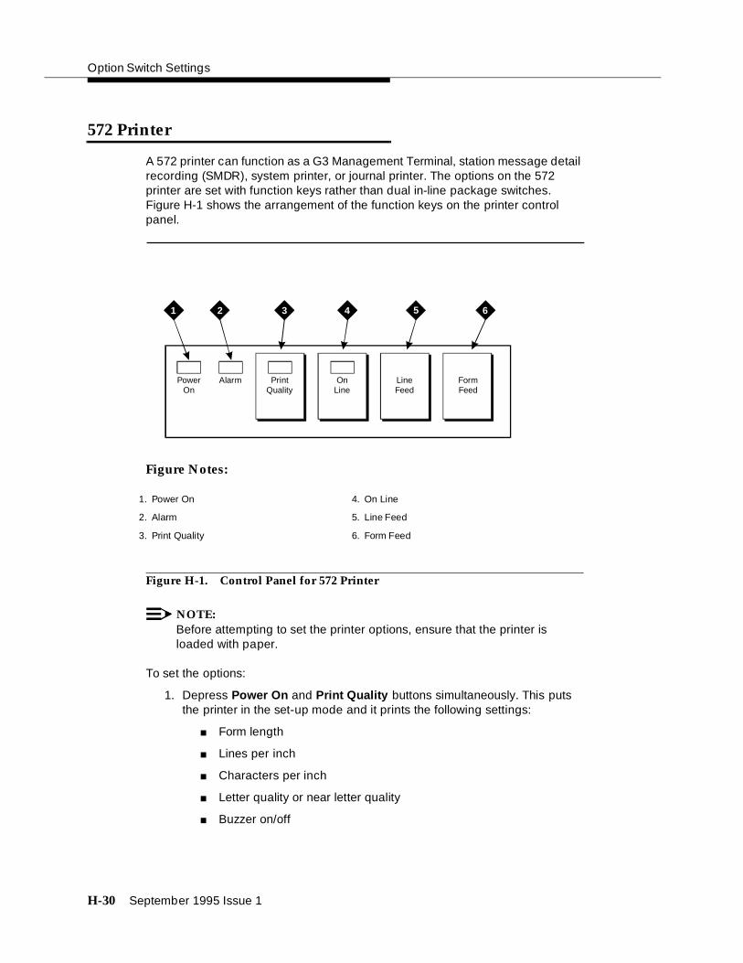
Option Switch Settings
H-30 September 1995 Issue 1
572 Printer
A 572 printer can function as a G3 Management Terminal, station message detail recording (SMDR), system printer, or journal printer. The options on the 572 printer are set with function keys rather than dual in-line package switches. Figure H-1 shows the arrangement of the function keys on the printer control panel.
Figure Notes:
Figure H-1. Control Panel for 572 Printer
NOTE:Before attempting to set the printer options, ensure that the printer is loaded with paper.
To set the options:
1. Depress Power On and Print Quality buttons simultaneously. This puts the printer in the set-up mode and it prints the following settings:
■ Form length
■ Lines per inch
■ Characters per inch
■ Letter quality or near letter quality
■ Buzzer on/off
PowerOn
Alarm PrintQuality
OnLine
LineFeed
FormFeed
3 4 51 62
1. Power On
2. Alarm
3. Print Quality
4. On Line
5. Line Feed
6. Form Feed

572 Printer
September 1995 Issue 1 H-31
2. If the printer is to be used with the G3 Management Terminal, station message detail recording (SMDR), or as a Journal printer, set the options as shown in Table H-22. If the printer is being used as the system printer, set the options as shown in Table H-23.
■ Use Line Feed button to step forward through the list of functions or use Form Feed button to step backward

Option Switch Settings
H-32 September 1995 Issue 1
.
Table H-22. 572 Printer Used with G3 Management Terminal,Station Message Detail Recording (SMDR) or Journal Printer
572 Printer Option Settings
Function Function Menu Menu
Number Name Number Status
01 FORM LENGTH 09 11
02 LPI 01 6
03 CPI 01 10
04 LQ or NLQ 01 LQ
05 BUZZER 01 ON
06 FONT 02 FONTCART
07 RESOLUTION 01 144
11 BUFFER 02 N-LINE
13 PW ON MODE 01 ON-LINE
14 DIRECTION 01 B1-DIR.1
15 BUFF FULL 02 LF + CR
16 P.E. 01 ACTIVE
17 AUTO CARRIAGE RETURN (CR)
01 CR + LF
18 ZERO 01 0
22 AUTO LINE FEED 01 CR ONLY
31 1’’ SKIP 01 OFF
32 CHAR.SET (GO, GL) 02 USA
33 CHAR.SET (G1, GR) 01 UK
34 CHAR SET (G2) 03 GE
35 CHAR SET (G3) 07 LINE DRAWING
81 OFF-LINE STATE 01 ALL RECEIVE
82 DSR 02 OFF
83 REQUEST TO SEND TIMING
01 RTS
84 CD 02 OFF
85 CLEAR TO SEND (CTS) 02 OFF
91 OVER RUN 02 256
92 DATA BIT 02 8

572 Printer
September 1995 Issue 1 H-33
93 PROTOCOL 03 XON/XOFF
94 STOP BIT 01 1
95 PARITY 01 NONE
96 PBS 01 9600
Table H-22. 572 Printer Used with G3 Management Terminal,Station Message Detail Recording (SMDR) or Journal Printer
572 Printer Option Settings
Function Function Menu Menu
Number Name Number Status

Option Switch Settings
H-34 September 1995 Issue 1
Table H-23. 572 Printer used as System Printer
572 Printer Option Settings
Function Function Menu Menu
Number Name Number Status
01 FORM LENGTH 09 11
02 LPI 01 6
03 CPI 01 10
04 LQ or NLQ 01 LQ
05 BUZZER 01 ON
06 FONT 02 FONTCART
07 RESOLUTION 01 144
11 BUFFER 02 N-LINE
13 PW ON MODE 01 ON-LINE
14 DIRECTION 01 B1-DIR.1
15 BUFF FULL 02 LF + CR
16 P.E. 01 ACTIVE
17 AUTO CARRIAGE RETURN (CR)
01 CR + LF
18 ZERO 01 0
22 AUTO LINE FEED 01 CR ONLY
31 1’’ SKIP 01 OFF
32 CHAR.SET (GO, GL) 02 USA
33 CHAR.SET (G1, GR) 01 UK
34 CHAR SET (G2) 03 GE
35 CHAR SET (G3) 07 LINE DRAWING
81 OFF-LINE STATE 01 ALL RECEIVE
82 DSR 02 OFF
83 REQUEST TO SEND (RTS) TIMING
01 RTS
84 CD 02 OFF
85 CLEAR TO SEND (CTS) 02 OFF
91 OVER RUN 02 256
92 DATA BIT 02 8
93 PROTOCOL 03 XON/XOFF

Station Message Detail Recording (SMDR) Interface Option Settings
September 1995 Issue 1 H-35
■ When the function to be changed is reached, press the On Line button. This activates the menu (available option settings) for the function. Use the Line Feed and Form Feed buttons to step through the options for the function.
■ When a desired option is located, press the Print Quality button.
■ Each time an option is set, the function and setting is printed.
1. Repeat Step 3 for each option to be set.
2. When the options are set, depress Print Quality button. The printer is now in the normal print mode.
Station Message Detail Recording(SMDR) Interface Option Settings
The interface between the G1 switch and station message detail recording equipment may be one of the following:
■ Modular processor data module (MPDM) or modular trunk data module (MTDM)—The recommended option settings are shown in the following table.
■ 212-type modem—The recommended option settings for the 212-type modem are shown in Table H-25.
■ TN726 Data Line circuit pack and an Asynchronous Data Unit — modular processor data module (MPDM), modular trunk data modules (MTDM), or 212-type modems are not required.
■ Connected directly to the DATA COMMUNICATIONS EQUIPMENT connector (Electronic Industries Association (EIA) Port) located on the back of the Control Carrier—modular processor data modules (MPDM), modular trunk data modules MTDM), or 212 modems are not required.
■ 7400A—The recommended option settings for the 7400A Data Module are given in this chapter under the heading: "7400A Option Settings" on page H-19.
94 STOP BIT 01 1
95 PARITY 01 NONE
96 PBS 04 1200
Table H-23. 572 Printer used as System Printer
572 Printer Option Settings
Function Function Menu Menu
Number Name Number Status
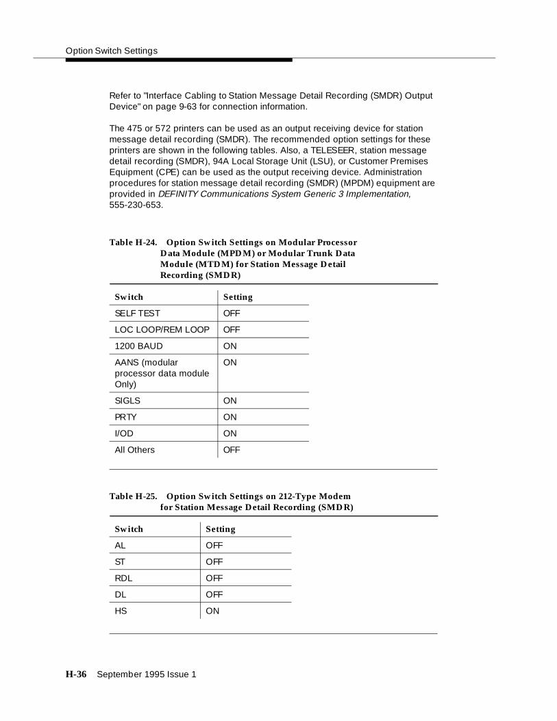
Option Switch Settings
H-36 September 1995 Issue 1
Refer to "Interface Cabling to Station Message Detail Recording (SMDR) Output Device" on page 9-63 for connection information.
The 475 or 572 printers can be used as an output receiving device for station message detail recording (SMDR). The recommended option settings for these printers are shown in the following tables. Also, a TELESEER, station message detail recording (SMDR), 94A Local Storage Unit (LSU), or Customer Premises Equipment (CPE) can be used as the output receiving device. Administration procedures for station message detail recording (SMDR) (MPDM) equipment are provided in DEFINITY Communications System Generic 3 Implementation, 555-230-653.
Table H-24. Option Switch Settings on Modular Processor Data Module (MPDM) or Modular Trunk Data Module (MTDM) for Station Message Detail Recording (SMDR)
Switch Setting
SELF TEST OFF
LOC LOOP/REM LOOP OFF
1200 BAUD ON
AANS (modular processor data module Only)
ON
SIGLS ON
PRTY ON
I/OD ON
All Others OFF
Table H-25. Option Switch Settings on 212-Type Modem for Station Message Detail Recording (SMDR)
Switch Setting
AL OFF
ST OFF
RDL OFF
DL OFF
HS ON

Audio Information Exchange (AUDIX) Interface Option Settings for G3i Systems
September 1995 Issue 1 H-37
Audio Information Exchange (AUDIX)Interface Option Settings for G3i Systems
AUDIX is sometimes connected to the switch through the processor interface circuit pack. The first circuit on the processor interface can be connected directly to the AUDIX through the PROCESSOR INTERFACE connector on the rear of the control carrier. Any of the remaining three circuits on the processor interface to be used to support AUDIX must be connected through a modular processor data module (MPDM) serving as the interface link for AUDIX. The option settings recommended for the modular processor data module (MPDM) in this application are shown in Table H-26.
TN760 Tie Trunk Circuit Pack Option Settings
The TN760 circuit pack interfaces between four 6-wire tie trunks and the time division multiplex (TDM) bus. Two tip and ring pairs form a 4-wire analog transmission line. An E and M pair is used for signaling. The E and M pair are direct current signaling leads used for call setup. The E lead receives signals from the tie trunk and the M lead transmits signals to the tie trunk.
To choose the preferred signaling format (Table H-30 and Table H-31), set switches on the TN760 circuit pack and administer the port per Figure H-2 and Table H-29.
Table H-26. Option Switch Settings on Modular Processor Data Module for AUDIX
Switch Setting
9600 BAUD ON
SYNC ON
INT ON
AANS ON
All Others OFF

Option Switch Settings
H-38 September 1995 Issue 1
! CAUTION:To prevent damage from static electricity, always wear an EMC wrist strap (comcode 900 698 226) when handling circuit packs or other switch components.
Table H-27. Signaling Formats for TN760
Mode Type
E & M Type I Standard (unprotected)
E & M Type I Compatible (unprotected)
Protected Type I Compatible, Type I Standard
Simplex Type V
E&M Type V
E&M Type V Revised
Table H-28. Signaling Type Summary
Signaling Transmit (M Lead) Receive (E Lead)
Type On-Hook Off-Hook On-Hook Off-Hook
Type I Standard
grd bat open*/bat grd
Type I Compatible
open*/bat grd grd open*/bat
Type V open/bat* grd open grnd
Type V Reversed
grd open grd open
* An open circuit is preferred over voltage.

TN760 Tie Trunk Circuit Pack Option Settings
September 1995 Issue 1 H-39
Figure H-2. TN760D Tie Trunk Circuit Pack (Component Side)
UNPROT
PROT
SMPLX
E&M
SMPLX
E&M
SMPLX
E&M
SMPLX
E&M
4 3 2 1
PORT 4 PORT 3 PORT 2 PORT 1
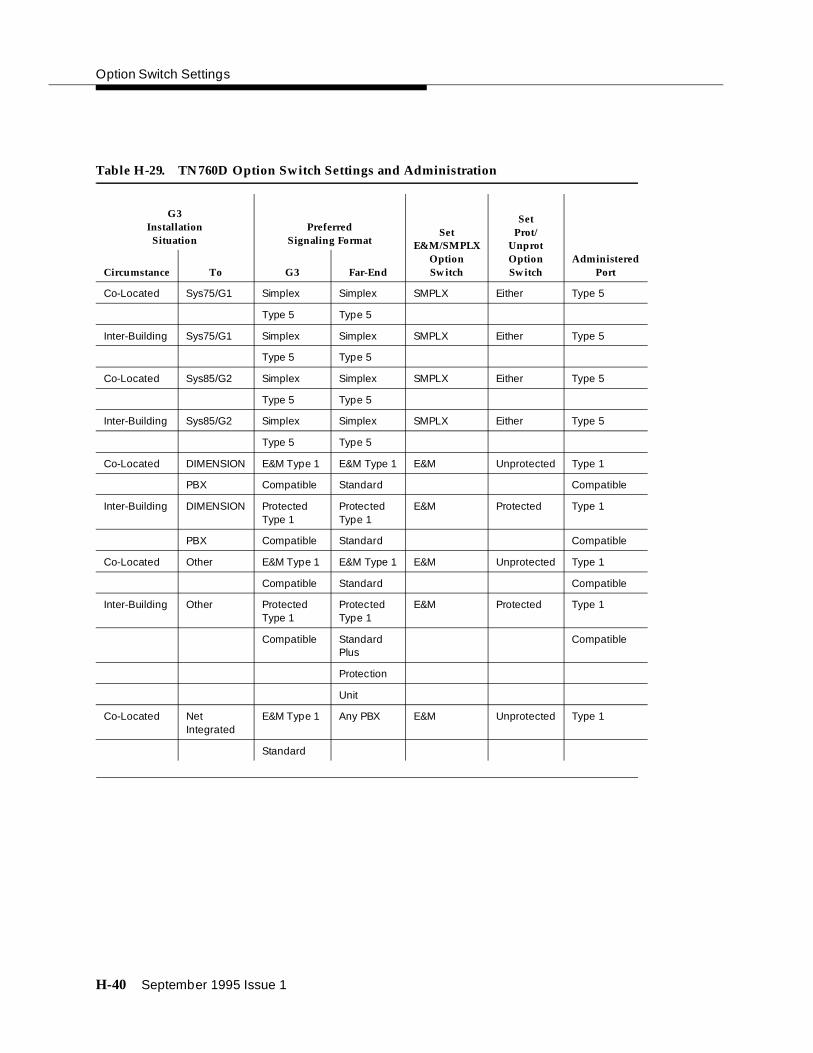
Option Switch Settings
H-40 September 1995 Issue 1
Table H-29. TN760D Option Switch Settings and Administration
G3Installation
Situation
SetProt/
UnprotOptionSwitch
PreferredSignaling Format
Set E&M/SMPLX
OptionSwitch
AdministeredPortCircumstance To G3 Far-End
Co-Located Sys75/G1 Simplex Simplex SMPLX Either Type 5
Type 5 Type 5
Inter-Building Sys75/G1 Simplex Simplex SMPLX Either Type 5
Type 5 Type 5
Co-Located Sys85/G2 Simplex Simplex SMPLX Either Type 5
Type 5 Type 5
Inter-Building Sys85/G2 Simplex Simplex SMPLX Either Type 5
Type 5 Type 5
Co-Located DIMENSION E&M Type 1 E&M Type 1 E&M Unprotected Type 1
PBX Compatible Standard Compatible
Inter-Building DIMENSION Protected Type 1
Protected Type 1
E&M Protected Type 1
PBX Compatible Standard Compatible
Co-Located Other E&M Type 1 E&M Type 1 E&M Unprotected Type 1
Compatible Standard Compatible
Inter-Building Other Protected Type 1
Protected Type 1
E&M Protected Type 1
Compatible Standard Plus
Compatible
Protection
Unit
Co-Located Net Integrated
E&M Type 1 Any PBX E&M Unprotected Type 1
Standard

TN464C, D, E, F Option Settings
September 1995 Issue 1 H-41
TN464C, D, E, F Option Settings
The TN464 circuit pack interfaces between a 24 or 32 channel Central Office (CO)/Integrated Services Digital Network (ISDN) or tie trunk and the Time Division Multiplex (TDM) bus.
The TN464C and TN464D act as Digital Service Level 1 (DS1)/E1 interfaces and Integrated Services Digital Network (ISDN) Primary Rate Interface (PRI) interfaces and have the following attributes:
■ 1,544-megabits per second (Mbps) Digital Service Level 1 (DS1) (24 channel integrated services digital network (ISDN)) and 2.048 megabits per second Mbps) E1 (32-channel Integrated Services Digital Network (ISDN)) transmission rates
■ Administrable A-law companding and Mu-law companding
■ Cyclical redundancy checking (CRC) 4 check
■ Stratum 3 clock compatibility
■ D-channel connectivity for Integrated Services Digital Network (ISDN) primary rate interface (PRI)
The TN464D is a superset of the TN464C and has the following additional attributes: supports digital release link tie trunks and MFC, R2 Direct Inward Dialed (DID) signaling. In addition to supporting tie trunk, Central Office (CO) trunk, and Direct Inward Dialed (DID) trunk protocols, the TN464D supports bit-oriented signaling protocols and bit-oriented Direct Inward Dialed (DID) signaling protocols.
The TN464C and TN464D have the following signal leads: LBACK2, LBACK1, LO, LO (out), LI, LI (in to Private Branch Exchange (PBX)).
TN464C/D Option Settings
To choose the bit rate and the line impedance match, set plugs (TN464 C & D) on the circuit pack. Insert the jumper blocks into the pins to join the center row of pins and the row designating the desired options.
Set the impedance and bit rate as follows:
Table H-30. Option Switch and/or Plug Settings on TN464C/D
120 Ohms Twisted Pair
75 Ohms Coaxial requiring 888A adapter
32 Channel 2.048 megabits per second
24 Channel 1.544 megabits per second

Option Switch Settings
H-42 September 1995 Issue 1
Figure H-3. Selection of 75 Ohm and 32 Channel Settings on TN464
TN464E/F Option Settings
The TN464 circuit pack interfaces between a 24 or 32 channel Central Office/Integrated Services Digital Network (CO/ISDN) or tie trunk and the Time Division Multiplex (TDM) bus.
Set switches E and F on the circuit pack to select bit rate and impedance match.
3
8
4
9
5
10
1
6
2
7
1. Backplane Connectors
2. 24/32 Channel Selector
3. 75/120 Ohm Selector
4. 24 Channel
5. 32 Channel (shown selected)
6. 120 Ohm
7. 75 Ohm (shown selected)
8. Faceplate
9. Connector
10. TN464C/D
Figure Notes:

TN464C, D, E, F Option Settings
September 1995 Issue 1 H-43
Set the impedance and bit rate as follows:
Table H-31. Option Switch Settings on TN464E/F
120 Ohms Twisted pair
75 Ohms Coaxial requiring 888A adapter
32 Channel 2.048 megabits per second
24 Channel 1.544 megabits per second

Option Switch Settings
H-44 September 1995 Issue 1
Figure H-4. TN464E/F Option Settings
3
8
4
9
5
10
1
6
2
7
1. Backplane Connectors
2. 24/32 Channel Selector
3. 75/120 Ohm Selector
4. Faceplate
5. 32 Channel
6. 120 Ohm (shown selected)
7. 24 Channel (shown selected)
8. 75 Ohm
9. Connector
10. TN464E/F
Figure Notes:

September 1995 Issue 1 I-1
IReferences
The following is a list of DEFINITY Generic 3 documents including a brief description of each document.
To order copies, refer to the address on the inside front cover. For additional DEFINITY documents, refer to the GBCS Publications Catalog, 555-000-010 available from the AT&T Customer Information Center.
Basic
The following are basic documents for anyone using DEFINITY.
Provides a detailed overview of the system including descriptions of many of the major features, applications, hardware, system capabilities, and the AT&T support provided with the system. This document reflects Generic 3 Version 2 software, but still contains relevant information.
Provides step-by-step procedures for the account team in determining the customer’s equipment and hardware requirements to configure a system according to the customer specifications. Includes detailed requirements and
An Introduction to DEFINITY Communications System Generic 3, Issue 1
555-230-023
DEFINITY Communications System Generic 3 Planning and Configuration, Issue 2
555-230-601

References
I-2 September 1995 Issue 1
block diagrams. This document reflects Generic 3 Version 2 software, but still contains relevant information.
Provides comprehensive technical descriptions of system features and parameters. Includes the applications and benefits, feature interactions, administration requirements, hardware and software requirements, and a brief discussion of data communications and private networking configurations.
Provides step-by-step procedures for preparing the hardcopy forms that correspond to the screens and are required to implement the features, functions, and services of the system. Includes procedures for completing a communications survey. Includes a complete set of blank forms (555-230-653B).
Provides additional blank hardcopy forms that correspond to the screens and are required to implement the features, functions, and services of the system.
Copies of these forms are automatically included with the DEFINITY Communications System Generic 3 Version 4 Implementation, Issue 1, 555-230-653. Use this order number to purchase additional forms.
Provides a technical description of the systems and is intended for service personnel, sales personnel, and customers needing a comprehensive overview of the system. Includes descriptions of hardware, software features, technical specifications, environment requirements, maintenance requirements, and illustration of components.
DEFINITY Communications System Generic 3 Feature Description, Issue 2
555-230-204
DEFINITY Communications System Generic 3 Version 4 Implementation, Issue 1
555-230-655
DEFINITY Communications System Generic 3 Version 4 Implementation Blank Forms, Issue 1
555-230-653B
DEFINITY Communications System Generic 3 System Description and Specifications, Issue 3
555-230-206

Basic
September 1995 Issue 1 I-3
Provides detailed descriptions of all the measurement, status, and security reports available in the system and is intended for administrators who validate traffic reports and evaluate system performance. This document was titled System Reports for earlier systems. Includes corrective actions for potential problems.
Provides descriptions of the procedures for installing and testing the system’s common equipment and adjuncts. Includes set up procedures for the system management terminal, power and grounding requirements, and testing steps. Includes compete details on system wiring. Provides both domestic and international information.
Provides procedures and information for hardware installation and initial testing of the DEFINITY Communications System Generic 3, models Generic 3i and Generic 3 single-carrier cabinet switches only. The United Kingdom version will be shipped with all single-carrier cabinet systems domestically.
Provides descriptions of the procedures for installing and testing the system’s common equipment and adjuncts. Includes set up procedures for the system management terminal, power and grounding requirements, and testing steps. Includes compete details on system wiring. Provides both domestic and international information for single carrier cabinets only. This document reflects Generic 3 Version 4.
DEFINITY Communications System Generic 3 Version 4 Traffic Reports, Issue 2
555-230-511
DEFINITY Communications System Generic 1 and Generic 3 Installation and Test, Issue 5
555-230-104
DEFINITY Communications System Generic 3s and Generic 3i Installation, Issue 1
555-230-894 UK English555-230-895 German555-230-896 French555-230-897 Spanish555-230-900 Chinese
DEFINITY Communications System Generic 3s and Generic 3i Installation (for Global M arket), Issue 1
555-230-104

References
I-4 September 1995 Issue 1
Provides procedures for an installation technician to convert an existing DEFINITY Generic 1, Generic 2, Generic 3 Version 1, Generic 3 Version 2, Generic 3 Version 4, or System 75 R1V3 to Generic 3 Version 4. Included are upgrade considerations, lists of required hardware, and step-by-step upgrade procedures. Also included are procedures to add control carriers, switch node carriers, port carriers, circuit packs, auxiliary cabinets, and other equipment.
Provide detailed descriptions of the procedures for monitoring, testing, and maintaining the systems. Included are maintenance commands, step-by-step trouble-clearing procedures, the procedures for using all tests, and explanations of the system’s error codes.
Provides information about the risks of telecommunications fraud and measures for addressing those risks and preventing unauthorized use of GBCS products. This document is intended for telecommunications managers, console operators, and security organizations within companies.
Provides descriptions of the peripheral equipment that can be used with System 75, System 85, and DEFINITY Communications System. This document is intended for customers and AT&T account teams for selecting the correct peripherals to accompany a system.
DEFINITY Communications System Generic 3 Version 1.1 - Version 4 Upgrades and Additions, Issue 2
555-230-107
DEFINITY Communications System Generic 3r Maintenance, Issue 4
555-230-105
DEFINITY Communications System Generic 3i/s/vs Maintenance, Issue 7
555-204-105
AT&T GBCS Products Security Handbook, Issue 4
555-025-600
DEFINITY Communications System and System 75 and System 85 Terminals and Adjuncts Reference, Issue 7
555-015-201
Call Center
September 1995 Issue 1 I-5
Provides detailed operating instructions for the system features on each type of voice terminal. Included are definitions of the voice features and user requirements.
Provides operating procedures for the Generic 1 Management Terminal and the G3 Management Terminal for Generic 3 Version 1 systems. This document is intended for the System Administrator. Also included is information on administrative tasks and system backup procedures.
Provides capability to produce laser-printed documentation for specific voice terminals. The software is supported by a comprehensive user’s guide and on-line help. This product requires a 386 PC, minimum of 6MB disk space, minimum of 4MB RAM, a printer supported by Microsoft GDI printer drive, and Microsoft Windows 3.1 or higher. A mouse is recommended.
Call Center
The following list of documents are Call Center specific. Refer also to the Basic DEFINITY documents.
Provides information on how to write, use, and troubleshoot vectors. Vectors are command sequences that process telephone calls in an Automatic Call Distribution (ACD) environment. It is provided in two parts: tutorial and reference.
The tutorial provides step-by-step procedures for writing and implementing basic call vector scripts.
DEFINITY Communications System Generic 1 and Generic 3 Voice Terminal Operations, Issue 1
555-230-701
DEFINITY Communications System Generic 1 and Generic 3 System Management, Issue 1
555-230-500
DEFINITY Communications System Generic 1, Generic 3, and System 75 Voice Terminal Guide Builder, Issue 1
555-230-755
DEFINITY Communications System Generic 3 Call Vectoring/EAS Guide, Issue 4
585-230-520

References
I-6 September 1995 Issue 1
The reference includes detailed descriptions of the call vectoring features, vector management, vector administration, adjunct routing, troubleshooting, and interactions with management information systems (including the Call Management System).
Provides detailed instructions on how to generate reports and manage the system and is intended for telecommunications managers wishing to use BCMS reports and system managers responsible for maintaining the system.
If Issue 4 is unavailable, use Issue 3.
Networks
The following list of documents are network specific. Refer also to the Basic DEFINITY documents.
Provides detailed information regarding the Wideband Switching feature for the system and is intended for users and technical support personnel involved with the installation, administration, and operation of this feature. This feature provides high speed end-to-end connectivity between customer endpoints where dedicated facilities are not economical or appropriate. The primary function is to support high speed video-conferencing and data applications.
Provides a technical description of digital trunks in the DEFINITY Communication Systems. This includes trunks conforming to the DS1 (Digital Service Level 1) standard (1.544 Mbps) and the CEPT1 standard and all other methods of signaling, including bit oriented signaling as well as Integrated Services Digital Network (ISDN) Primary Rate Interface (PRI) signaling. This document includes background information on these topics, information on how digital trunk capabilities have been designed into the DEFINITY systems and information for field personnel and customers on how to provision and administer digital trunk capabilities and features. Provides both domestic and international information.
DEFINITY Communications System Generic 3 Basic Call Management System (BCMS) Operations, Issue 4
555-230-704
DEFINITY Communications System Generic 3 Wideband Technical Reference, Issue 1
555-230-230
DEFINITY Communications System Generic 2.2 and Generic 3 Version 2 DS1/CEPT1/ISDN PRI Reference Manual, Issue 1
555-025-107

Application Specific
September 1995 Issue 1 I-7
Application Specific
The following list of documents are application specific. Refer also to the Basic DEFINITY documents.
Provides detailed descriptions of the difference between features and administrative forms for systems Generic 2 to Generic 3 Version 4 and is intended for AT&T personnel and customers involved in planning upgrades and migrations from an older system. Includes descriptions of new administrative commands.
Provides procedures and directions for the account team and customer personnel for planning and implementing the CallVisor Adjunct/Switch Application Interface (ASAI) PBX-Host environment. The CallVisor ASAI is a communications interface allowing adjunct processors to access switch features and to control switch calls. It is implemented using an Integrated Services Digital Network (ISDN) Basic Rate Interface (BRI). Included are hardware and software requirements.
Provides detailed layer 3 protocol information regarding the CallVisor Adjunct/Switch Application Interface (ASAI) for the systems and is intended for the library or driver programmer of an adjunct processor to create the library of commands used by the applications programmers. Describes the Integrated Services Digital Network (ISDN) message, Facility Information Elements, and information elements.
Provides detailed information regarding the CallVisor Adjunct/Switch Application Interface (ASAI) for the systems and is intended for the application designer responsible for building and/or programming custom applications and features.
DEFINITY Communications System Generic 2 to Generic 3 Version 4 Transition Reference, Issue 1
555-230-636
DEFINITY Communications System Generic 3 CallVisor ASAI Planning Guide, Issue 4
555-230-222
DEFINITY Communications System Generic 3 CallVisor ASAI Protocol Reference, Issue 4
555-230-221
DEFINITY Communications System Generic 3 CallVisor ASAI Technical Reference, Issue 4
555-230-220
References
I-8 September 1995 Issue 1
Provides procedures for installation, administration, and maintenance of the CallVisor LAN Gateway application and is intended for system administrators, telecommunications managers, Management Information System (MIS) managers, LAN managers, and AT&T personnel. The LAN Gateway application provides ASAI functionality using 10Base-T Ethernet rather than BRI as a transport media.
Provides information for use by agents after they have completed Automatic Call Distribution (ACD) training. Includes descriptions of features and the procedures for using them.
Provides information for use by supervisors after they have completed Automatic Call Distribution (ACD) training. Includes descriptions of features and the procedures for using them.
Provides operating instructions for the attendant console. Included are descriptions of the console control keys and functions, call-handling procedures, basic system troubleshooting information, and routine maintenance procedures.
DEFINITY Communications System Generic 3 CallVisor LAN Gateway Installation, Administration, and Maintenance, Issue 1
555-230-223
DEFINITY Communications System Generic 3 Automatic Call Distribution (ACD) Agent Instructions, Issue 4
555-230-722
DEFINITY Communications System Generic 3 Automatic Call Distribution (ACD) Supervisor Instructions, Issue 4
555-230-724
DEFINITY Communications System Generic 1 and Generic 3 Console Operation, Issue 2
555-230-700

Application Specific
September 1995 Issue 1 I-9
Provides operating instructions for the attendant console. Included are descriptions of the console control keys and functions, call handling, basic system troubleshooting information, and routine maintenance procedures.
Provides an overview of the features available for use by the lodging and health industries to improve their property management and to provide assistance to their employees and clients. Included are brief definitions of many of the system features, descriptions of the hardware, planning considerations, and list of the system capabilities.
Provides step-by-step procedures for using the features available for use by the lodging and health industries to improve their property management and to provide assistance to their employees and clients. Includes detailed descriptions of reports.
DEFINITY Communications System Generic 1 and Generic 3 Console Quick Reference, Issue 1
555-230-890 UK English555-230-891 German555-230-892 French555-230-893 Spanish555-230-920 Chinese
An Introduction to DEFINITY Communications System Generic 3 Hospitality Services, Issue 1
555-230-021
DEFINITY Communications System Generic 1 and Generic 3 User’s Guide Hospitality Operations, Issue 2
555-230-723

Issue 1 September 1995 ABB-1
ABBAbbreviations
A
ACAlternating Current
ADUAsynchronous Data Unit
AMIAlternate Mark Inversion
ANSIAmerican National Standards Institute (U.S.A.)
AWGAmerican Wire Gauge
B
BCMSBasic Call Management System
BRIBasic Rate Interface
C
CASCentralized Attendant Service or Call Accounting Sys-tem
CBCCoupled Bonding Conductor
CCITT Consultative Committee for International Telephone and Telegraph
CCCountry Code
CEPT1European Conference of Postal and Telecommunica-tions Rate 1
CIClock Input
cmCentimeter
CMSCall Management System
COCentral Office
CRCarriage Return
CTSClear To Send
D
DCDirect Current
DCEData Communications Equipment
DCSDistributed Communications System
DDCDirect Department Calling
DODDirect Inward Dialing
DIWD-inside wire
DS1Data Services 1
DSRData Set Ready
DTEData Terminal Equipment
E
EIExpansion Interface
EIAElectronics Industry Association
EPNExpansion Port Network

Abbreviations
ABB-2 Issue 1 September 1995
F
FCCFederal Communications Commission (U.S.A.)
G
G3MTGeneric 3 Management Terminal
H
HZHertz
I
I/OInput/Output
ininch
INADSInitialization and Administration System
ISDNIntegrated Services Digital Network
L
LCDLiquid Crystal Display
LEDLight Emitting Diode
LSULocal Storage Unit
M
MPDMModular Processor Data Module
MTManagement Terminal
MTDMModular Trunk Data Module
N
NECNational Electrical Code (U.S.A.)
P
PBXPrivate Branch Exchange
PDMProcessor Data Module
PDUPower Distribution Unit
PPNProcessor Port Network
PMSProperty Management System
PRIPrimary Rate Interface
PXPBX transmit
R
RTSRequest To Send

Abbreviations
Issue 1 September 1995 ABB-3
S
SCCSingle Carrier Cabinet
SMDRStation Message Detail Recording
SPESwitch Processor Element
SPIDService Profile Identifier
SWGStandard Wire Gauge (United Kingdom)
T
TDMTime Division Multiplexer
TMTest Mode
TXTerminal transmit
U
UCD Uniform Call Distribution
UPSUninterruptible Power Supply
W
WATSWide Area Telecommunications System (U.S.A.)

Issue 1 September 1995 IN-1
INIndex
Numerics
103A wall jack, 6-7103JR modem
switch settings, H-210-AWG wire, 4-3110 SYSTIMAX, 2-2116A EIA ground isolator, installation procedure, 6-3201CR modem
switch settings, H-4202SR modem
switch settings, H-6208BR modem
switch settings, H-9212AR modem
switch settings, H-11, H-14212-type modem
option settings, H-352224A modem
switch settings, H-17, H-1824-hour clock
conversion table, 7-1325-pair I/O cables, 4-342-wire analog sta, 9-52-wire digital station wiring example, 9-52-wire telephones, installation procedure, E-1302B Attendant Console
connection illustration, 9-14example, 9-2illustration, 9-14
400B2 power adapter, 9-3475 printer, H-21
option settings, H-35476 printer, H-214-wire telephones, installation procedure, E-1572 printer, H-30
option settings, H-356-AWG ground wire, 4-3, A-27400A data module, 6-7
option settings, H-198-pin line jack
figures, E-2, E-3pinouts, E-3
9400-series telephonescord routing for desktop, E-5cord routing for wall mount, E-8distance limitations, E-4installation procedure, E-1testing, E-9
9403wall mounting, E-6wiring, E-2
9410
wall mounting, E-69434
wiring, E-294A Local Storage Unit, H-359823A transceiver, 4-19, 4-209823B transceiver, 4-19, 4-20
A
AC powercheck power, 2-6connect cabinet cords, 4-6grounding, 2-8receptacle location, 4-2
AC-powered switchturn on procedure, 7-3
activate system, overview, 1-5adapters
400B2, 9-3address plugs, 4-29adjunct power, 9-5
connecting, 9-3administer system
data, 9-66overview, 1-7
ADXmessage on AUDIX LCD display, C-2, C-4
AINITmessage on AUDIX LCD display, C-4
alarmwiring example, 9-5
alarmslog of, 7-9
A-Law companding, 7-7, H-41American Wire Gauge, F-1analog station
wiring example, 9-5analog tie trunk
wiring example, 9-6announcement
delete procedure, 10-12integrated test procedure, 10-12playback procedure, 10-12record procedure, 10-12
APP connector information, 9-15, 9-17–9-20approved ground, A-1Argentina
country code, 7-8required hardware, D-2
AT control modem, H-19attendant console, 9-2
connection illustration, 9-14maximum cabling distance, 9-2test procedure, 10-8
AUDIXimportant caution about powering down, 7-8power down procedure, C-1

Index
IN-2 Issue 1 September 1995
power up procedure, C-1trademark information, xvii
Australiacountry code, 7-8required hardware, D-3
Autowraprequired setting for G3MT, 6-6
Aux Conn outputs, 9-11AUX connector
pin designations, 9-10, 9-15auxiliary connector outputs, 9-10auxiliary equipment pin designations, 9-15, 9-17–9-20availability, system, 1-1AWG to SWG wire conversion, F-1AWG wire conversion, F-1
B
B25A cable, 6-7backplane, port cabinet, 4-29backup translations, 7-16basic rate interface
see also BRItest procedure, 10-15
batterybackup power, 4-14connecting, 4-5
Baud Rate, required setting for G3MT, 6-6BCMS, for remote connection, 6-7Belgium
country code, 7-8required hardware, D-4
bit ratesetting, H-41, H-42
bit-oriented signaling, H-41books, ordering related documents, xviBOOT message on AUDIX LCD display, C-4BRI
multipoint cabling distances, 9-45terminating resistor, 9-39test procedure, 10-15
BTEST message on AUDIX LCD display, C-4buried ground, A-2
C
cabinetaddress plugs, 4-29attaching to floor, B-1aux conn outputs, 9-11backplane, 4-29cable clamps, 4-34clip, 4-35definition of, 8-1
earthquake protection, B-1fastening together, B-4ground bar, 4-3ground plate, 4-30installation overview, 1-3position, 4-2slots, 4-29stabilizing, 4-35stabilizing for earthquake, B-4, F-1unpacking overview, 1-3
cable clamps, 4-34cable label and colour code., 5-7Cable Labels, 5-7cable slack manager, 5-3
floor plan including, 2-2floor plan requirements, 2-4illustration, 5-5
cables25-pair I/O, 4-34diagrams, 9-15, 9-17–9-20external trunk, 5-7fiber-optic, 4-19installation overview, 1-4inter-cabinet, 4-15, 4-17labeling, 5-7outputs for control carrier, 9-10routing guidelines, 5-3TDM bus, 4-15, 4-17, 4-32wallfield, 4-34
cabling systems, 2-2Canada
required hardware, D-2carriage bolts, B-2CAS+, for remote connection, 6-7caution
always wear EMC wrist strap when handling circuit packs or switch components, 7-2, H-38
avoiding disk crash, 7-8do not route fiber-optic cables and B25A cables
together, 4-24grounding compliance with electrical codes, 4-14grounding must comply with electrical codes, 4-8installing G3MT with DC-powered system or electromag-
netic shielding, 6-1regarding 116A EIA ground isolator, 6-1regarding 9400-series telephones, E-1regarding location of MSP-1 power supply, 9-36regarding MSP-1 power supply, 9-36reseating purple-labled tone detector/generator circuit
pack, 7-8reseating white-labeled control circuit packs, 7-8safeguarding craft password, 7-9safety precautions for power supply, 9-35saving translations on white translation card, 7-15shut down AUDIX system before reseating, 7-8take care when opening carton, 3-2
CDRU, for remote connection, 6-7changing
password, 7-9

Index
Issue 1 September 1995 IN-3
system-parameters country options, 7-6system-parameters maintenance, 7-14
Check Parity, required setting for G3MT, 6-6China
country code, 7-8required hardware, D-5
circuit breaker, 4-5circuit pack
pin, 9-13circuit pack configuration
test procedure, 8-4test procedure, circuit packs
configuration test procedure, 8-19circuit packs
configuration test procedure, 8-4ISDN wiring, 9-13NT1 wiring, 9-13pin designations, 9-15, 9-17–9-20required by country, D-1–D-19TN2198
wiring, 9-13circuit, power arrangements, 2-6clamps, cable, 4-34clip, cabinet, 4-35CO trunk, H-41
wiring example, 9-5code
grounding requirements, A-1section 250-81, A-1
colors, of wire, F-1commands
G3MT introduction, 7-4list configuration, 8-19refresh spe, 8-13reset system interchange, 8-13set expansion-link, 8-18set tone-clock, 8-17status system all-cabinets, 8-12, 8-17, 8-18status system cabinets-all, 8-13test board, 8-14test inads-link, 10-15test shadow-link, 8-11test tdm port-network, 8-15test tone-clock 1a, 8-10
compandingA-Law, H-41mode, 7-6Mu-Law, H-41
concrete encased ground, A-2conductor, coupled bonding, 2-8conduit, as ground, A-2connecting
battery, 4-5grounds, A-2
connectorsdata communications equipment, H-35RX, 4-19TX, 4-19
consoleattendant, test procedure, 10-8selector, test procedure, 10-9
control carrier outputs cable, 9-10copper wire, A-2Cost Allocator, 6-7country codes, 7-8country options, setting, 7-6country-specific hardware, D-1–D-19coupled bonding conductor, 4-3
connecting, 2-8description, 2-8
craft password, changing, 7-9critical reliability, 1-1, 1-2
testing systems, 8-11, 8-12, 8-17cross-connect field, 2-2, 2-8
cable slack manager, 5-3connecting to, 5-1connection, 4-19coupled-bonding conductor, 2-8fiber-optic cable, 4-19illustration, 5-3limitations, 4-2location, 5-2, 5-3recommended hardware, 2-2
Czechoslovakiacountry code, 7-8required hardware, D-6
D
dangerhandling cabinet requires two people, as it weighs 130
lbs/60 kgs, 3-1if label is different than voltage type at your site, do not
connect - get a replacement power supply, 3-4, 4-6take care when cutting and removing bands on packing,
3-1Data Bits
required setting for G3MT, 6-6data communications equipment connector, H-35date, set procedure, 7-11day of the week
table of English names, 7-12DB9 (on back of PC), 6-7DC power
connecting G3MT to a switch, 6-3signaling leads, H-37
DC-powered switchturn on procedure, 7-3
DCS switch settings, H-2DEFINITY, C-1
trademark information, xviiDEFINITY AUDIX System
power down procedure, C-1power up procedure, C-1

Index
IN-4 Issue 1 September 1995
designationsauxiliary leads at AUX connector, 9-10, 9-15port board and telephone, 9-13
DID signaling, H-41DID trunk
protocols, H-41wiring example, 9-5
digital station wiring example (2-wire), 9-5digital tie trunk, wiring example, 9-9direct connect systems, 4-19direct department calling
testing queue warning indicator, 10-10D-lead modem, H-19documents, ordering additional, xviDS1
connection, 9-9interface, H-41
duplication of systems, 1-1DUPLICATION OPTION TERMINAL
connecting G3MT procedure, 6-3
E
E1 interface, H-41earthquake front plate, B-4earthquake protection procedures, B-1–B-6EIA port, H-35electrical codes
international, G-1North America, G-1
electromagnetic shielding, 4-35, B-4emergency power, 4-14emergency transfer, test procedure, 10-13English day names
table of, 7-12English month names
table of, 7-12Enter Key, required setting for G3MT, 6-6Equador
country code, 7-8required hardware, D-6
equipment closetsdetermine location, 2-9
equipment room floorplan, 2-2examples
2-wire digital station wiring, 9-5302B Attendant Console, 9-2analog station wiring, 9-5analog tie trunk wiring, 9-6CO trunk wiring, 9-5DID trunk wiring, 9-5digital tie trunk wiring, 9-9telephone connection wiring, 9-2
expansion interfaceboards, test procedure, 8-14exchange, test procedure, 8-17
expansion links, service state, 8-2expansion port network
duplication, 1-1testing systems, 8-15, 8-16
external alarmwiring example, 9-5
external ringing, test procedure, 10-9external trunk, 5-7
F
fiber-optic cabledirect connect systems, 4-19duplication, 1-1installation, 4-19lightwave tranceiver, 4-19
floor ground, A-2floorplan, equipment room, 2-2Font Size, required setting for G3MT, 6-6France
country code, 7-8required hardware, D-6
front mounting angle, B-1front plate, B-4
G
G3 Management Terminalinstallation procedures, 6-1see also G3MT
G3MTcommands, introduction, 7-4floorplan requirements, 2-2install procedure, 6-1installation overview, 1-4printers, 6-2procedure to connect remote, 6-7required settings, 6-6requirements, 6-1set up procedure, 6-6
Germanycountry code, 7-8required hardware, D-6
global country code, 7-8Greece
country code, 7-8required hardware, D-8
ground plate, 4-34, B-4, F-1installing, 4-29, 4-30
ground ring, A-2grounding
6-AWG wire, 4-3AC power, 2-8acceptable mediums, A-1

Index
Issue 1 September 1995 IN-5
approved, 2-8building steel frame, A-1concrete encased, A-2connecting, A-2floor, A-2ground plate, B-4, F-1ground ring, A-2layout, 2-6planning, 2-8rules, 2-8terminal, A-2warning, A-2water pipe, A-2
H
hardwarefiber-optic, 4-19required by country, D-1–D-19
high reliability, 1-1, 1-2testing systems, 8-11, 8-12
Hong Kongcountry code, 7-8required hardware, D-8
hospitality featurejournal printer, H-28
Hungarycountry code, 7-8required hardware, D-10
I
impedance, setting, H-41, H-42Imperial Wire Ga, F-1INADS
test procedure, 10-14install PPN cabinet, 4-2integrated announcement
test procedure, 10-12inter-cabinet cables, 4-15, 4-17international electrical codes, G-1ISDN, H-41
2-wire BRI line, wiring, 9-13BRI
fanout of multipoint installations, 9-45multipoint cabling distances, 9-46port board and telephone pin designations, 9-13terminating resistor, 9-39test procedure, 10-15
PRI interface, H-41isolator
116A EIA ground, 6-1installation procedure, 6-3
Italycountry code, 7-8required hardware, D-10
J
jack, wiring, E-3Japan
country code, 7-8required hardware, D-12
journal printer, H-28option settings, H-21
L
labelon power supply, warning, 3-4
labeling cables, 5-7layout
grounding, 2-6power, 2-6
lead designations, 9-158-pin line jack, E-3port board, 9-13port board and telephone, 9-13telephones, 9-13
lightwave transceiver, for fiber-optic cables, 4-19line impedance, setting, H-41LINX trademark information, xviilist configuration all
command, 8-4screens, 8-5–8-9
list configuration command, 8-19Local Storage Unit (LSU), H-35log in procedure, 7-5logoff procedure, 7-17LSU (Local Storage Unit), H-35
M
M25A cable, 6-7M25B cable
using to connect G3MT, 6-3Macedonia
country code, 7-8manual power up and down procedures for AUDIX, C-1metric wire conversion, F-1Mexico
country code, 7-8required hardware, D-12
modem212-type option settings, H-35

Index
IN-6 Issue 1 September 1995
AT control, H-19D-lead, H-19pooling, 6-7pooling, switch settings, H-2
modularplug, 9-3trunk data modules, H-1
month namestable of English, 7-12
mounting bolts, B-1MPDM (modular processor data modules), H-1MSHUT
message on AUDIX LCD display, C-1MSP-1 power supply, 9-5, 9-34MTDM, H-1Mu-Law companding, 7-7, H-41multiple-carrier cabinets, see DEFINITY Communications
System Generic 1 and Generic 3 Installation and Test manual, #555-230-104, comcode 107009417
multipointfigure, 9-46tables of cabling distances, 9-46
music on hold, test procedure, 10-13
N
National Electrical Codegrounding rules, 2-8Section 250-81, A-1
NEC, see National Electrical CodeNetherlands
country code, 7-8required hardware, D-13
night ringing, test procedure, 10-9North American electrical code, G-1NT1 wiring, 9-13
O
option switch settings, H-1ordering related DEFINITY books, xviOS message on AUDIX LCD display, C-4OSINIT message on AUDIX LCD display, C-4outputs
aux conn, 9-11outputs cable for control carrier, 9-10
P
packet bus administration, 7-14parallel printers, 6-2Parity, required setting for G3MT, 6-6
parts10-AWG wire, 4-36-AWG ground wire, 4-3carriage bolts, B-2earthquake front plate, B-4front mounting angle, B-1mounting bolts, B-1stiffener, B-3thread-forming screws, B-2, B-4
password, 7-6changing, 7-9craft, changing, 7-9requirements for valid, 7-10
PBX cross-connect field, 2-8pin designations, 9-15
auxiliary equipment, 9-15, 9-17–9-20auxiliary leads, 9-10, 9-15circuit packs, 9-15, 9-17–9-20telephones, 9-13
pinout informationport board, 9-13telephones, 9-13
pinouts, 9-158-pin line jack, E-3auxiliary, 9-17–9-20circuit packs, 9-17–9-20
plan and prepare site, procedure, 2-1playback announcement, test procedure, 10-12plugs, address, 4-29PMS, for remote connection, 6-7Poland
country code, 7-8required hardware, D-14
port board and telephone pin designations, 9-13port board pin designations, 9-13port cabinet backplane, 4-29port labels, 5-7port network
definition, 8-1positioning cabinet, 4-2power
circuit, 2-6connecting for adjuncts, 9-3connecting local to modular plug, 9-3emergency, 4-14for adjuncts, 9-5layout arrangement, 2-6planning, 2-6receptacle location, 4-2standby, 4-14supply, 4-5, 9-5transformer, A-2warning for voltage type, 3-4
power down AUDIX, procedure, C-1power supply
1145B -48V, 9-261146 B -48V, 9-26label not matching voltage type at your site, 3-4, 4-6MSP-1, 9-34

Index
Issue 1 September 1995 IN-7
power upAC-powered switch, procedure, 7-3AUDIX procedure, C-1DC-powered switch, procedure, 7-3
PPN cabinetinstalling, 4-2
printer475 switch settings, H-21572 option settings, H-30connecting to G3MT, 6-2journal option settings, H-21option settings, H-20parallel, 6-2serial, 6-2
processor interface circuit packAUDIX connections, H-36switch settings, H-2
processor port network, duplication, 1-1protection
earthquake, B-1electromagnetic, B-4
provisioning plan, 2-9
Q
queue warning indicator, test procedure, 10-10
R
REBOOT PERFORMED, 7-4recorded announcement, test procedure, 10-12red lights
what to do about, 7-8refresh spe command, 8-13reliability
critical, 1-1, 1-2testing systems, 8-11, 8-12, 8-17
high, 1-1, 1-2testing systems, 8-11, 8-12
overview, 1-1standard, 1-1, 1-2
remote access, test procedure, 10-14Report Scheduler, system printer, H-21required hardware
by country, D-1–D-19requirements
country hardware for grounding, A-1protective grounding, A-1
reset system interchange command, 8-13RF shielding, 4-35, B-4ringing
external, test procedure, 10-9night, test procedure, 10-9
routing cables, 5-3
Russiacountry code, 7-8required hardware, D-14
RX connector, 4-19
S
Saudi Arabiacountry code, 7-8required hardware, D-15
save translations, 7-15screens
G3MT introduction, 7-4screws, thread-forming, B-2, B-4selector console, test procedure, 10-9serial printers, 6-2set expansion-link command, 8-18set tone-clock command, 8-17setting
bit rate, H-41, H-42line impedance, H-41, H-42
setting date and time, procedure, 7-11shadow link
test procedure, 8-11shielding, electromagnetic, 4-35, B-4Shockwatch
trademark information, xviisignaling leads, DC power, H-37signaling, bit-oriented, H-41Singapore
country code, 7-8required hardware, D-16
single-point ground terminal, A-2site planning and preparation
overview, 1-3procedure, 2-1
slack managerfloor plan including, 2-2
Slovakiarequired hardware, D-6
SMDR, H-20option settings, H-34output receiving device, H-35printer, H-30
Spaincountry code, 7-8required hardware, D-16
SPIDtest procedure for, 10-16
stabilizing cabinets, 4-35for earthquakes, B-4, F-1
standard reliability, 1-1, 1-2standby power, 4-14Station Message Detail Recording (SMDR), H-20status system all-cabinets
command, 8-1, 8-12, 8-17, 8-18

Index
IN-8 Issue 1 September 1995
screens, 8-2–8-4status system cabinets-all command, 8-13stiffener, B-3Stop Bit, required setting for G3MT, 6-6Styrofoam, trademark information, xviiSWG wire conversion, F-1switch processing element
interchange test procedure, 8-12test procedure, 8-11
switch settings103JR modem, H-2201CR modem, H-4202SR modem, H-6208BR modem, H-9212-type modem, H-35470 printer, H-28471 printer, H-28475 printer, H-21, H-35476 printer, H-21572 printer, H-30, H-357400A, H-19asynchronous 212AR modem, H-11asynchronous 2224A modem, H-17DCS, H-2journal printer, H-21, H-28modem pooling, H-2modular processor data modules (MPDM), H-1printer, H-20processor interface, H-2SMDR, H-34synchronous 212AR modem, H-14synchronous 2224A modem, H-18system printer, H-21TN464 circuit pack, H-41, H-42TN760 tie trunk, H-37
system printer, H-30option settings, H-21
system-parameters maintenance, 7-14SYSTIMAX, 2-2
trademark information, xvii
T
Table 5-1, 5-7Taiwan
country code, 7-8required hardware, D-16
TDM bus, H-41cable, 4-32cables, 4-15, 4-17service state, 8-2terminator, 4-15, 4-17
telecommunications cablesinstalling, 5-1
telephonepin designations, 9-13
telephone callsmaking test calls, 10-2–10-8making test calls for single-cabinet switch, 10-2making test calls for three-cabinet switch, 10-4making test calls for two-cabinet switch, 10-3
telephone connection example, 9-2telephones
9400cord routing for desktop, E-5cord routing for wall mount, E-8testing, E-9
9403wiring, E-2
9434wiring, E-2
button labels, E-10install and wire overview, 1-6test overview, 1-7test procedures, 10-1wiring, E-2
TELESEER, H-35template, mounting, B-1terminal
location, 2-8type, 7-6
TERMINAL connectorconnecting G3MT, 6-3
terminating resistor, 9-39terminator, TDM bus, 4-15, 4-17terminology translations, D-1test
system overview, 1-5, 8-1telephones, overview, 1-7
test board command, 8-14test inads-link command, 10-15TEST message on AUDIX LCD display, C-1test shadow-link command, 8-11test tdm port-network 1 command, 8-9test tdm port-network 2 command, 8-15test tone-clock 1a command, 8-10test tone-clock command, 8-16Thailand
country code, 7-8thread-forming screws, B-2, B-4tie trunk
analog wiring example, 9-6circuit pack option settings, H-37digital wiring example, 9-9
Tiltwatch trademark information, xviitime division multiplexor
see also TDMtest procedure, 8-9, 8-15
time, set procedure, 7-11TN2147 circuit pack, 6-7TN2181 circuit pack
pin designations, 9-13TN2182 circuit pack, 7-7TN2183 circuit pack, 6-7

Index
Issue 1 September 1995 IN-9
TN2198wiring, 9-13
TN420C circuit pack, 7-7TN464 circuit pack, 6-7
option settings, H-41, H-42TN465 circuit pack, 6-7TN742 circuit pack, 6-7TN746 circuit pack, 6-7TN747 circuit pack, 6-7TN748 circuit pack, 7-7TN753 circuit pack, 6-7TN754 circuit pack, 6-7TN760 circuit pack, 6-7
option settings, H-37TN767 circuit pack, 6-7TN769 circuit pack, 6-7TN777B circuit pack, 7-2, 7-16TN778 circuit pack
administration required, 7-14tone clock
duplication, 1-1interchange, test procedure, 8-17test procedure, 8-16
tone clock boards, test procedure, 8-10tone clocks
service state, 8-2tone detector circuit pack
administering, 7-7tools needed to install switch, 2-4transceiver, for fiber-optic cables, 4-19transfer, emergency
test procedure, 10-13translations
backup procedure, 7-16save procedure, 7-15
Transmission Flow Controlrequired setting for G3MT, 6-6
trunk aux field, 5-7TX connector, 4-19
U
uniform call distributiontesting queue warning indicator, 10-10
Uninterruptible Power Supply, 4-14United Kingdom
country code, 7-8required hardware, D-18
United Statescountry code, 7-8required hardware, D-2
UPS, 4-14MSP-1 power supply, 9-5
USA, country code, 7-8
V
Venezuelacountry code, 7-8required hardware, D-19
voltage warning, 3-4
W
wall mounting9403 and 9410 telephones, E-6
wall switch, 4-2warning
connections to ground inside power equipment room should be done by licensed electrician, A-2
ground, A-2safety instructions for power supply, 9-33
water pipe grounding, A-2wire
bare copper, A-2colors, F-1grounding, A-2
wire conversioncommon wire colors, F-1solid conductor
AWG to metric, F-4AWG to SWG, F-4SWG to metric, F-4
stranded wireAWG to metric, F-1AWG to SWG, F-1SWG to metric, F-1
wiring2-wire digital station example, 9-59403 telephones, E-2analog station wiring example, 9-5analog tie trunk example, 9-6CO trunk example, 9-5DID trunk example, 9-5digital tie trunk example, 9-9ISDN BRI 2-wire line, 9-13NT1, 9-13pin designations, 9-10, 9-15, 9-17–9-20procedures, 9-1telephone connection example, 9-2telephone jack, E-3telephones, E-2