Definition and Classification of Terms for HVDC Networks · A HVDC grid is an interconnected HVDC...
22
Definition and Classification of Terms for HVDC Networks Til Kristian Vrana,* Sintef Energi Keith Bell, University of Strathclyde Poul Ejnar Sørensen, DTU Wind Energy Tobias Hennig, Fraunhofer IWES Abstract: A systematic terminology for the field of HVDC networks has been developed, closing the gap between the well-established terminologies from AC power systems and HVDC technology. The most relevant items, topologies and concepts have been given clear and unique defined names, and these have been classified in a systematic way. The motivation for this work has been to help to reduce the communication problems that are emerging when power system engineers talk to HVDC technology engineers. The main guidelines underpinning the approach taken here is to minimise conflicts with the mentioned two existing terminologies and with existing publications on HVDC networks. A significant effort has been made to make the terminology "future-proof" not only covering today's HVDC technology but also potential future developments like large meshed HVDC grids and high power HVDC-HVDC converters. Index Terms: HVDC Grids HVDC Networks HVDC Power Systems Multi-Terminal HVDC Super Grid * [email protected]
Transcript of Definition and Classification of Terms for HVDC Networks · A HVDC grid is an interconnected HVDC...

Definition and Classification of Terms for HVDC Networks
Til Kristian Vrana,* Sintef Energi
Keith Bell, University of Strathclyde
Poul Ejnar Sørensen, DTU Wind Energy
Tobias Hennig, Fraunhofer IWES
Abstract:
A systematic terminology for the field of HVDC networks has been developed, closing the gap between
the well-established terminologies from AC power systems and HVDC technology. The most relevant
items, topologies and concepts have been given clear and unique defined names, and these have been
classified in a systematic way.
The motivation for this work has been to help to reduce the communication problems that are emerging
when power system engineers talk to HVDC technology engineers. The main guidelines underpinning
the approach taken here is to minimise conflicts with the mentioned two existing terminologies and with
existing publications on HVDC networks. A significant effort has been made to make the terminology
"future-proof" not only covering today's HVDC technology but also potential future developments like
large meshed HVDC grids and high power HVDC-HVDC converters.
Index Terms:
HVDC Grids
HVDC Networks
HVDC Power Systems
Multi-Terminal HVDC
Super Grid
1. Introduction
The scientific community has gained a strong interest in the field of High Voltage Direct Current
(HVDC) networks. In most publications these are referred to as HVDC grids or HVDC systems. The
entire field of research is at the moment lacking a systematic terminology, as there are two existing
fields merging: Electrical power systems (AC) and HVDC technology. This can result in communication
problems, as many terms in use do not have a clear and unique definition.
The North Sea Offshore and Storage Network (NSON) Initiative [1] has identified this lack of a
/terminology and definition of terms as problematic for the development of the electrical infrastructure
in the North Sea region, and therefore worked to develop the missing /terminology, which is presented
in this article and may be likened to taxonomies used in other fields such as zoology and computer
science. In the presentation that follows, the terms that are defined here are written in italics.
1.1. Simplifications
In this article, a single-line-representation of all HVDC infrastructure is used. This is necessary to enable
for a systematic view upon the network topology, without having to go into technical detail.
What is referred to here as one DC bus is in technical detail either two busses (e.g. positive and negative
poles) or three busses (additional ground), and one DC transmission line might take the form of one
conductor (with a ground or sea return), two (positive and negative poles) or three conductors (for
positive and negative poles plus a metallic earth return). A particular HVDC system is described as
having one single voltage level, even though, for example, an asymmetric monopole has a different
voltage at the return (e.g. -150 kV / 0 kV). These details are, however, not in focus in this article.
All converters in the discussion presented below are regarded as ideal converters. Only the input and
output are considered, and all technical details of the internal topology including intermediate voltage
levels are disregarded.
Very short transmission lines are ignored. Two busses that are co-located and directly connected (by a
very short transmission line) are combined into one equivalent bus (e.g. the conductors connecting
converter terminals of a back-to-back system). Only lines beyond negligible length are considered as
lines.
1.2. Visualisations
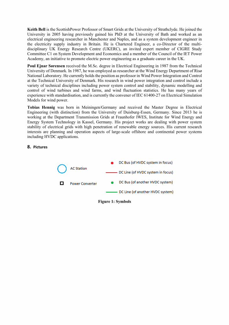
The concepts are visualised with figures using the symbols explained in Error! Reference source not
found.Error! Reference source not found..
PLACE FIGURE 1 HERE
The CIGRE B4 DC Test Grid [2] drawn with this simplified visualisation scheme is shown in Figure 2.
This can be compared with the regular electrical drawing of the same grid, shown in Error! Reference
source not found. in Section 4.
PLACE FIGURE 2 HERE
2. Definitions for HVDC Networks
The relevant definitions for HVDC networks are given in this section.
2.1. HVDC Networks
A HVDC network is an electrical network that utilises high DC voltage does not need to be purely based
on DC can also include conversion through intermediate AC stages (DC-AC-DC conversion), but it
cannot include AC transmission lines. A network consisting of AC and DC transmission lines (such as
the interconnected European electric power grid) is a hybrid AC+DC network. Hybrid AC+DC networks
are not the focus here.

In this definition a distinction is made between two types of HVDC networks: HVDC systems and
HVDC grids.
2.1.1. HVDC System
A HVDC system is an autonomous HVDC network, which operates with a single high DC nominal
voltage. In a HVDC system, all busses (defined in Section 2.3) are directly connected by conductors.
Protection devices like circuit breakers can be series connected within a HVDC system, even though that
is not really a direct conductor connection. An example of a HVDC system is shown in Figure 3.
PLACE FIGURE 3 HERE
To be regarded as part of a single HVDC System, any DC-DC power converters must be series connected
between two busses within that HVDC system. This is the case if these two busses are directly connected
by conductors, meaning there is a direct connection path between the busses in parallel to the DC-DC
converter, creating a loop within the HVDC system (controllable mesh, Section 2.4.2). Without that
parallel direct connection path, the DC-DC converter would split the HVDC system into two HVDC
systems connected by the converter.
A HVDC system can only have one nominal voltage level, due to the direct conductor connection. This
is similar to a synchronous AC power system, which can only have one frequency.
If a short-circuit appears within a HVDC system, the voltage collapses in the entire HVDC system, if this
is not prevented by a protection system, which quickly separates the faulty part from the healthy part.
This is why large HVDC systems would have demanding requirements towards the protection system.
This short-circuit behaviour is one of the most relevant differences between HVDC systems and HVDC
grids.
A HVDC system can stand alone, or it can be part of a HVDC grid. In that case, it could also be referred
to as a HVDC sub-system, to highlight the fact that it is not standing alone.
2.1.2. HVDC Grid
A HVDC grid is an interconnected HVDC network, consisting of two or more HVDC systems, which
can be referred to as sub-systems in that case. Unlike a HVDC system, a HVDC grid does not require
direct conductor connection of all busses. A HVDC grid can therefore (but does not need to) have
multiple voltage levels, connected by power converters. A similarity to AC can be observed when
regarding interconnected AC grids, consisting of several synchronous (sub-) systems which can (but do
not need to) have multiple frequencies. In the European AC grid, all (sub-) systems have the same
frequency (50 Hz), but in the Japanese AC grid, the two (sub-) systems have different frequencies (50
Hz and 60 Hz). An example of a HVDC grid (consisting of two HVDC systems) is shown in Figure 4.
PLACE FIGURE 4 HERE
Different HVDC systems can be counted as belonging to the same HVDC grid if:
They are connected by a DC-DC converter
They connect to the same AC station via AC-DC converters (see supernode, Section 2.3.5)
As stated, the HVDC grid can also include conversion through intermediate AC stages (DC-AC-DC
conversion), but it cannot include AC transmission lines.
If a short-circuit appears within a HVDC grid, the voltage does not collapse in the entire HVDC grid,
but only in the affected HVDC (sub-) system. This is why large HVDC grids do not necessarily have as
demanding requirements towards the protection system as large HVDC systems do, since the sectioning
of a HVDC grid into several smaller HVDC (sub-) systems can avoid a short-circuit from critically
disturbing the entire HVDC grid. This advantage of a HVDC grid requires sufficient fault-blocking
capabilities of all converter interfaces between the HVDC (sub-) systems.

The word 'grid' somehow implies the presence of loops (defined in Section 2.4). However, a large HVDC
network consisting of several HVDC systems with several voltage levels, but without any loops, could
theoretically be realised in the future. Such a non-looped HVDC network with a tree-like structure should
theoretically not be called a grid, as it lacks the characteristic loops of a grid. However, AC distribution
systems are often also called 'distribution grids', even though many distribution systems do not have
loops. It seems that the word 'grid' has already been used for non-looped networks for many years, so
the use of the word 'grid' for networks without loops has to be accepted.
In several publications, large HVDC systems are called HVDC grids, even though they do not consist of
at least two HVDC (sub-) systems. This is done without stating clearly what the difference is exactly
between a large HVDC system and a HVDC grid. However, it can generally be observed that the term
HVDC system [3] is mostly used for smaller well-defined HVDC networks, while HVDC grid [4] often
refers to future larger HVDC networks like the envisioned European Super Grid.
2.2. Edges
An edge generally is a connection between two vertices, as known from graph theory. Regarding HVDC
networks, an edge is defined as a connection between two busses of that network or the connection of
one bus of that network with the external world.
This connection to the external world could be to an AC system, to a source (generation) or to a sink
(load). For a HVDC system (not for a HVDC grid), it could also be the connection to another HVDC
system by a DC-DC converter.
Parallel edges that connect to the same busses on both ends (e.g. double circuit lines, parallel converters)
are seen as one edge of the network (observable when comparing Figure 2 with Error! Reference
source not found.). This is relevant in the context of connection points (defined in Section 2.3.1).
2.2.1. Branch
A branch of a HVDC network is an edge that connects two busses of that network. Branches should
have some 'significant' length or should connect locations which are electrically separate. If two busses
are directly connected by a conductor with 'insignificant' length, they appear as one bus from a network
point-of-view.
Branches are generally either HVDC lines or DC-DC converters. A HVDC transmission line always
connects two busses of a HVDC network, so it is a branch of that network. A DC-DC converter
connecting two busses, which belong to the same HVDC system, is also a branch of any type of HVDC
network. A DC-DC converter connecting two busses, which do not belong to the same HVDC system,
is a more complicated case, treated in Section 2.2.3.
Examples of branches are shown in Error! Reference source not found..
PLACE FIGURE 5 HERE
2.2.2. Terminal
A terminal of a HVDC network is an edge that connects one bus of that network with the external world
(anything that is not part of the HVDC network). Terminals act as sources and/or sinks, or in other words
as inputs and/or outputs to or from the HVDC network.
In most cases, a terminal is a connection of a HVDC network to a power converter. However, other non-
converter-type terminals are theoretically possible (e.g. DC load, DC generator), but these are not
common, especially at high DC voltage.
All AC-DC converters are terminals to any type of HVDC network (shown in Error! Reference source
not found.). A DC-DC converter connecting two busses, which do not belong to the same HVDC system,
is a more complicated case, treated in Section 2.2.3.

When considering the entire complete hybrid AC+DC grid, only generation and load would remain as
terminals, while all converters become branches. However, the focus here is on HVDC networks and
not on hybrid AC+DC networks.
PLACE FIGURE 6 HERE
Terminals are the points of the network where most of the inflow and outflow (current/power) is located.
Concerning current, this flow-based definition holds very well for HVDC systems. Only small amounts
of current enter and leave the HVDC system at branches. This is the leakage current on transmission
lines and the difference between input and output current of a DC-DC converter (which is small for a
DC-DC converter with the same voltage level on both sides). For HVDC grids with different voltage
levels, this flow-based definition only holds when using per unit values. This is because of the significant
difference between input and output current of a DC-DC converter connecting two different voltage
levels (which disappears when converting to per unit).
Concerning power, this flow-based definition is not as exact as for currents. This is due to the
transmission losses on the lines (mostly power losses, very little current losses). However, when
considering power, HVDC grids with different voltage levels can be considered without having to look
at per unit values.
It is important to distinguish between busses and terminals. These two terms are often confused, as the
majority of existing HVDC systems has one terminal per bus. Based on the definition of a terminal as
given here, a terminal is treated as an edge because of the net flow through it, whereas a bus has net
flow of zero.
2.2.3. HVDC System Terminal / HVDC Grid Branch Duality
A special case that needs extra attention is a DC-DC converter, which connects to two different HVDC
systems (shown in Error! Reference source not found.). This would typically be the case, when two
different voltage levels are connected.
PLACE FIGURE 7 HERE
Regarding the HVDC grid (which includes both HVDC systems), the DC-DC converter appears as a
branch of the grid (just like any other DC-DC converter). Regarding the two HVDC systems, the DC-
DC converter appears as a terminal for both systems (unlike other DC-DC converters than can appear
as a branch within one HVDC system).
2.3. Busses
A bus is a point in the HVDC network where two or more edges are connected. Different types of busses
are defined here. In graph theory the term 'vertex' is used for what here is called a bus.
2.3.1. Connection Point
A connection point is defined as a bus where exactly two edges are connected together (shown in Error!
Reference source not found.). This is typically a connection of a converter to a transmission line or an
overhead line to a cable. Since a double circuit line counts as one edge and not as two, a bus where a
converter is connected to a double circuit line is considered a connection point.
PLACE FIGURE 8 HERE
Theoretically, any point on any line (e.g. a cable joint) could be seen as a connection point of two line
segments. Whether such connection points are relevant to be considered or not depends highly on the
specific study case.
Connection points are not significant for power flow calculations, as the flow out of the first edge is
exactly the flow into the other edge. There is no degree of freedom, so connection points (unlike the
other bus types) need not add to the complexity of a power flow calculation.
2.3.2. Node
A node is a bus where at least three edges meet, and at least one of the edges has to be a terminal.
A bus appears as a node in both types of HVDC network if it has an edge, which connects to something
outside the HVDC grid, and not just to another voltage level (which is part of the HVDC grid but not of
the HVDC system). This usually means a connection to AC.
Examples of busses, which are nodes for both types of HVDC networks, are shown in Error! Reference
source not found..
PLACE FIGURE 9 HERE
2.3.3. Hub
A hub is a bus where at least three branches meet, and where no terminals are connected. A hub here
refers to a DC hub as a constituent part of a HVDC network, and not to any kind of AC bus. There are
similarities with the term 'tee point' as used for AC networks.
A bus appears as a hub in both types of HVDC networks if it does not have an edge, which connects to
something outside the HVDC system, not even to another voltage level (which is part of the HVDC grid
but not of the HVDC system). DC-DC converters can be connected to a hub, if they are internal to the
HVDC system, meaning that they connect to the same HVDC system on both ends. They are therefore
branches of that HVDC system and not terminals.
Examples of busses, which appear as hubs for both types of HVDC networks, are shown in Error!
Reference source not found.. The DC-DC converters shown in the examples are internal to the HVDC
system.
PLACE FIGURE 10 HERE
2.3.4. HVDC System Node / HVDC Grid Hub Duality
The definitions of nodes and hubs are identical for HVDC grids and HVDC systems, but the definitions
of edges (branches or terminals) are not identical. This duality of branches and terminals in the case of
DC-DC converters (explained in Section 2.2.3) results also in a duality of nodes and hubs. A bus with
an edge, which is a dual terminal/branch edge, can be (but does not need to be) a dual node/hub bus.
A bus...
where at least three edges meet
where at least one of the edges is a dual branch/terminal edge
(DC-DC converter connecting to another HVDC system)
that has no connection to something outside the HVDC grid
...appears as a node for the HVDC system, but at the same time appears as a hub for the HVDC grid.
This is due to the fact that the DC-DC converter appears as a terminal to the HVDC system but as a
branch to the HVDC grid. Examples are shown in Error! Reference source not found..
PLACE FIGURE 11 HERE

However, it should be noted that:
all busses that are nodes of a HVDC grid also appear as nodes of the corresponding HVDC
system, but not vice versa.
all busses that are hubs of a HVDC system also appear as hubs of the corresponding HVDC grid,
but not vice versa.
2.3.5. Supernode
A supernode is not really a bus, but rather a cluster of busses. It consists of at least two (DC) busses and
one AC station, where the busses are connected to the same AC station through AC-DC converters.
Supernodes are especially relevant in the context of pseudo-meshes (defined in Section 2.4.3).
Examples of supernodes can be seen in Error! Reference source not found.. The left-hand example
shows a supernode connecting two busses of the same HVDC system, while the right-hand example
shows a supernode connecting to different HVDC systems. All the converters shown are terminals, as
they are AC-DC converters.
PLACE FIGURE 12 HERE
If the two DC busses of a supernode have the same voltage level, a switch could be placed between
them, being able to short-circuit them together. This would turn the supernode into a regular node (with
two parallel AC-DC converters). It enables the flexible reconfiguration between node and supernode
state, depending on what is better for the specific power flow situation.
A connection to two distant AC stations in the same AC system (synchronous area) does not qualify as
a supernode, as it would include significant geographical transmission distance on the AC side into the
supernode, which is in conflict with the 0-dimensional "point" character of a bus. For this definition,
geographical distance is used instead of electrical distance. Within an AC station, there is almost no
geographical distance, but the electrical distance usually is significant, due to the transformer series
inductance.
A supernode can be seen as part of a HVDC network, even though it might contain an intermediate AC
stage. The supernode (one AC station bus and two AC-DC converter edges) has some similar properties
as an edge (DC-DC converter). It connects two DC busses and controls the flow between them.
However, it does not fully behave like an edge, as the inflow on one side does not need to be equal (or
almost equal) to the outflow of the other side.
Many dedicated DC-DC converter topologies also contain an intermediate AC stage (which is normally
not operated at a typical AC system nominal frequency such as 50Hz). This does not, however, qualify
as supernode as the AC bus is only an AC 'connection point' between the two converter stages, without
AC 'node' characteristics. The DC-DC converter with an intermediate AC stage therefore truly behaves
like an edge, while the supernode only shares some properties with an edge.
2.4. Loops
A loop is a circular structure of branches within a HVDC network. A loop is referred to as a cycle in
graph theory. The different types of loops are defined here.
2.4.1. Mesh
A mesh is a loop within a HVDC system, where no power electronic converters are inserted in series into
the loop, so all flows follow Ohm's and Kirchhoff's laws. The power flow in a mesh cannot be fully
controlled. A mesh is shown in Error! Reference source not found..
PLACE FIGURE 13 HERE

2.4.2. Controllable Mesh
A controllable mesh is a loop within a HVDC network, where flows can be controlled by at least one
DC-DC converter inserted in series into the loop as a branch. Examples for controllable meshes are
shown in Error! Reference source not found..
PLACE FIGURE 14 HERE
The definition of a controllable mesh is identical for HVDC grids and HVDC systems. However, a
controllable mesh of a HVDC grid can consist of different HVDC lines at different voltage levels
belonging to different HVDC systems, which all are part of the same HVDC grid (as shown on the right
of Error! Reference source not found.). This is a realistic scenario for future HVDC grids that will
consist of several voltage levels.
2.4.3. Pseudo-Mesh
A pseudo-mesh is a loop within the HVDC network, which contains at least one supernode (Section
2.3.5). This means that not the entire loop is DC, but it is closed though a DC-AC-DC connection with
two AC-DC converters and one AC station. Examples of pseudo-meshes are shown in Error! Reference
source not found..
PLACE FIGURE 15 HERE
The definition of a pseudo-mesh is identical for HVDC grids and HVDC systems. However, a pseudo-
mesh of a HVDC grid can consist of different HVDC lines at different voltage levels belonging to
different HVDC systems, which all are part of the same HVDC grid (as shown on the right of Error!
Reference source not found.). This is a likely scenario for future HVDC grids that will consist of
several voltage levels.
If the loop would consist of AC and DC transmission lines, it is not regarded as a DC pseudo-mesh. It
would be a hybrid AC+DC loop [5], but these are not considered here, as they do not belong to HVDC
networks but to hybrid AC+DC networks.
3. Properties of HVDC Systems
The main attributes of a HVDC system are its complexity (in the sense of the number of inputs and
outputs), its topology and its size. These three important aspects are classified here.
3.1. HVDC System Complexity
The input-output complexity of a HVDC system depends on the number of terminals. A distinction is
generally made between two-terminal systems and multi-terminal systems.
3.1.1. Two-Terminal HVDC System
A two-terminal system is a HVDC system with two terminals. Only the number of terminals is specified,
and it does not say anything about the number of busses and branches. However, systems with two
busses and one transmission line are most common (Section 0). Some possible two-terminal systems are
shown in Error! Reference source not found..
PLACE FIGURE 16 HERE
The term two-terminal system also includes back-to-back converters with a single DC bus and no
transmission line (e.g. first stage of Tres Amigas [6]). However, such a system can also be considered
as an AC-AC converter.
A two-terminal system can also have three or more busses. An example of this is when both cables and
overhead lines are applied.
The term "point-to-point HVDC system" is often used synonymously for two-terminal system. This is,
however, not correct since a two-terminal back-to-back system is not a point-to-point system. A point-
to-point system requires 'significant' geographical distance between the points. For this definition,
geographical distance is used instead of electrical distance. Within a back-to-back system, there is almost
no geographical distance, but the electrical distance can be significant, e.g. if there is a DC series
inductor.
3.1.2. Multi-Terminal HVDC System
A multi-terminal system is a HVDC system with at least three terminals. Only the number of terminals
is specified, and it does not say anything about the number of busses and branches. Any number of
terminals (including zero) can be located at a bus. Some examples of multi-terminal systems are shown
in Error! Reference source not found..
PLACE FIGURE 17 HERE
The term multi-terminal system also includes multi-terminal back-to-back converters with a single DC
bus and no transmission line (e.g. Shin-Shinano [7], described in Section 3.2.1).
A multi-terminal system can be a point-to-point system if at least one of the two busses with terminals
has more than one terminal (e.g. one AC-DC converter and one DC-DC converter). Two terminals of a
HVDC system are considered to be at the same bus, if they are geographically co-located, as explained
in Section 1.1.
3.2. HVDC System Topologies
The different HVDC system topologies are defined here.
3.2.1. Back-to-back HVDC System
A back-to-back HVDC system is a HVDC system with a single bus and no branches (examples shown
in Error! Reference source not found.).
PLACE FIGURE 18 HERE
It usually has two terminals (left part of Error! Reference source not found.), but also a system with
three terminals has been realised (right part of Error! Reference source not found., e.g. Shin-Shinano
[7]). More than three terminals are theoretically also possible, but this has never been applied yet, and
it seems challenging to imagine an application where such a system would be the appropriate technical
solution.
3.2.2. Point-to-Point HVDC System
A point-to-point HVDC system is a system where all terminals are located at exactly two busses. This
implies a minimum requirement of at least two busses. Examples of point-to-point systems are shown
in Error! Reference source not found.. A point-to-point system can also have three or more busses.
This would typically appear when both cables and overhead lines are applied, leading to additional
connection points (seen in the lower two examples of Error! Reference source not found.).
PLACE FIGURE 19 HERE
The term "point-to-point" HVDC system is often used synonymously for "two-terminal" HVDC system.
This is however not correct:
Not every two-terminal system is a point-to-point system. If both terminals are located at the
same bus (back-to-back system), the two-terminal system is not a point-to-point system.
Not every point-to-point system is a two-terminal system. A point-to-point system can be a
multi-terminal system if at least one of the two busses with terminals has more than one terminal
(e.g. one AC-DC converter and one DC-DC converter). This is shown in in Error! Reference
source not found. (the two point-to-point systems on the right are multi-terminal systems).
The term "point-to-point" system therefore contains no information about the number of terminals, but
it rather relates to the HVDC system topology. This confusion originates from the fact that most of the
existing HVDC systems are point-to-point two-terminal HVDC systems.
3.2.3. Radial HVDC system
A radial HVDC system is a multi-terminal HVDC system with no loops, and with at least three busses
that have at least one terminal each. A radial HVDC system has exactly one branch less than the number
of busses. Radial systems have the structure of a mathematical tree, as known from graph theory. All
branches of a radial system need to be transmission lines, as a DC-DC converter 'branch' would split
the system into two systems, forming one grid. Examples are shown in Error! Reference source not
found..
PLACE FIGURE 20 HERE
3.2.4. Pseudo-Meshed HVDC System
A pseudo-meshed HVDC system is a multi-terminal HVDC system with at least one pseudo-mesh and
with no controllable meshes or meshes. Examples are shown in Error! Reference source not found..
PLACE FIGURE 21 HERE
No pseudo-meshed HVDC system exists or is planned at the moment of writing.
3.2.5. Controllable-Meshed HVDC System
A controllable-meshed HVDC system is a multi-terminal HVDC system with at last one controllable
mesh and with no simple meshes. Examples are shown in Error! Reference source not found..
PLACE FIGURE 22 HERE
No controllable-meshed HVDC system exists or is planned at the moment of writing.
3.2.6. Meshed HVDC System
A meshed HVDC system is a multi-terminal HVDC system with at least one mesh. Examples are shown
in Error! Reference source not found..
PLACE FIGURE 23 HERE
No meshed HVDC system exists or is planned at the moment of writing.
3.3. HVDC System Size
In the literature, there is often reference to 'large' HVDC systems (e.g. [8]). There are some attributes
which are granted to a 'large' HVDC system, but there usually is no definition of when a HVDC system

is large. Some other technical phenomena become relevant only for 'very large' HVDC systems, but also
here a definition is usually missing.
The terms 'large' and 'very large' are more often used in combination with HVDC grids rather than with
HVDC systems. This is mostly based on the general consensus that large and very large HVDC networks
will likely be HVDC grids consisting of several HVDC (sub-)systems.
3.3.1. Large HVDC system
A HVDC system can be considered large if its power flows are so large that a failure of the HVDC system
would cause a severe disturbance for the connected AC grids. This especially relates to the primary
control reserves or frequency containment reserves of the AC grids. A failure of a line or converter
always needs to be acceptable within the security margins, but keeping reserves for the failure of a large
HVDC system could not normally be justified. A large HVDC system rather needs sophisticated control
and protection systems to avoid this scenario. This indicates advantageous properties of a large HVDC
grid compared to a large HVDC system, since a HVDC grid is more robust and has less strict protection
requirements [9].
There is no clear limit when a HVDC system can be considered large. However, a simple 'rule of thumb'
can be proposed: "A HVDC system is large if the sum of all converter power ratings is one order of
magnitude larger than the power rating of a single converter."
3.3.2. Very large HVDC system
A HVDC system can be considered very large when the power rating of the largest converter station is
insignificant compared to the sum of all converter power ratings. In this case heavily centralised control
concepts, e.g. where a single converter is operated as slack bus, become questionable. Very large HVDC
systems are not foreseen in the near future.
There is no clear limit when a HVDC system can be considered very large. However, a simple 'rule of
thumb' can be proposed: "A HVDC system is very large if the sum of all converter power rating is two
orders of magnitude larger than the power rating of a single converter."
4. Example: The CIGRE B4 DC Test Grid
The CIGRE B4 DC Test Grid [2] (shown in Error! Reference source not found.) is given as an
example to explain the definitions.
PLACE FIGURE 24 HERE
It is a HVDC grid, consisting of three HVDC systems (DCS1, DCS2 and DCS3). DCS1 and DCS2 are
displayed in light blue and DCS3 in dark blue.
All the AC-DC converters are terminals. All the transmission lines are branches. The DC-DC converter
at location B1 is a branch, because it is connected to the same HVDC system (DCS3) on both ends. The
DC-DC converter at location E1 is a dual terminal / branch. It appears as a terminal to both of the HVDC
systems at each end (DCS2 and DCS3) but it appears as a branch to the HVDC grid.
The bus types of the CIGRE B4 DC Grid Test System are specified in Error! Reference source not
found.. The HVDC grid contains two supernodes, at locations A1 and B2. Bus Bb-E1 is a dual hub /
node.
PLACE TABLE I HERE
The HVDC systems DCS1 and DCS2 do not contain loops. DCS3 contains a mesh and a controllable
mesh. The HVDC grid contains all three HVDC systems, and since it contains DCS3, it automatically
also contains the mesh and the controllable mesh from DCS3. However, the HVDC grid also contains a

pseudo-mesh which is formed by the HVDC systems DCS2 and DCS3, together with the two supernodes
A1 and B2. It should be noted that a HVDC grid can contain a pseudo-mesh even though none of its
constituent HVDC subsystems contains one (as explained in Section 2.4.3). The loops are specified in
Error! Reference source not found..
PLACE TABLE II HERE
The defined properties of HVDC systems are given in Error! Reference source not found..
PLACE TABLE III HERE
5. Acknowledgement
This publication is a result of work by the North Sea Offshore and storage Network (NSON) Initiative,
which is an activity of the European Energy Research Alliance (EERA) Joint Programme (JP) on Wind
Energy (http://www.eera-set.eu/eera-joint-programmes-jps/wind-energy).
6. References
[1] Fraunhofer IWES, "North Sea Offshore Network (NSON)",
http://www.energiesystemtechnik.iwes.fraunhofer.de/de/projekte/suche/laufende/nson.html,
2015.
[2] T. K. Vrana, S. Dennetiere, Y. Yang, J. Jardini, D. Jovcic, and H. Saad, "The CIGRE B4 DC
Grid Test System", Electra, vol. 270, 2013.
[3] M. Szechtman, T. Wess, and C. V. Thio, "A benchmark model for HVDC system studies",
International Conference on AC and DC Power Transmission, 1991.
[4] G. Asplund, K. Linden, A. Marzin, C. Barker, J. Rittiger, N. Pahalawaththa, R. Iravani, D. V.
Hertem, D. Jovcic, K. Soegaard, U. Baur, P. Christensen, P. Labra, M. Rashwan, J. Berteen, S.
Cole, E.-D. Wilkening, D. Westermann, C. Yue, and W. Jialiang, "CIGRE WG B4.52 -
Technical Brochure 533 - HVDC Grid Feasibility Study", CIGRE, 2013.
[5] J. M. Birkebaek, A. Jaederstroem, R. Paprocki, and O. Ziemann, "Using HVDC Links to cope
with Congestions in Neighbouring AC Networks", presented at the PSCC, Stockholm, 2011.
[6] N. M. Kirby, N. M. MacLeod, D. Stidham, and M. Reynolds, "Tres Amigas : A flexible
gateway for renewable energy exchange between the three asynchronous AC networks in the
USA", presented at the CIGRE, Paris, 2012.
[7] T. Nakajima and S. Irokawa, "A Control System for HVDC Transmission by Voltage Sourced
Converters", 1999.
[8] C. D. Barker, C. C. Davidson, D. R. Trainer, and R. S. Whitehouse, "Requirements of DC-DC
Converters to facilitate large DC Grids", CIGRE Paris, 2012.
[9] K. R. W. Bell, L. Xu, and T. Houghton, "Considerations in design of an offshore network",
CIGRE Science & Engineering, vol. 1, 2015.
7. Biographies
Til Kristian Vrana graduated from the Academic School of the Johanneum in 2001 in
Hamburg/Germany. He received his bachelor in electrical engineering and information technology in
2005 and his master in electric power engineering in 2008, both at RWTH Aachen University in
Aachen/Germany. He achieved his doctoral degree in 2013 at the Norwegian University of Science and
Technology NTNU in Trondheim/Norway. Currently he is working as a research scientist in the energy
systems department at Sintef Energi in Trondheim/Norway.
Keith Bell is the ScottishPower Professor of Smart Grids at the University of Strathclyde. He joined the
University in 2005 having previously gained his PhD at the University of Bath and worked as an
electrical engineering researcher in Manchester and Naples, and as a system development engineer in
the electricity supply industry in Britain. He is Chartered Engineer, a co-Director of the multi-
disciplinary UK Energy Research Centre (UKERC), an invited expert member of CIGRE Study
Committee C1 on System Development and Economics and a member of the Council of the IET Power
Academy, an initiative to promote electric power engineering as a graduate career in the UK.
Poul Ejnar Sørensen received the M.Sc. degree in Electrical Engineering in 1987 from the Technical
University of Denmark. In 1987, he was employed as researcher at the Wind Energy Department of Risø
National Laboratory. He currently holds the position as professor in Wind Power Integration and Control
at the Technical University of Denmark. His research in wind power integration and control include a
variety of technical disciplines including power system control and stability, dynamic modelling and
control of wind turbines and wind farms, and wind fluctuation statistics. He has many years of
experience with standardisation, and is currently the convener of IEC 61400-27 on Electrical Simulation
Models for wind power.
Tobias Hennig was born in Meiningen/Germany and received the Master Degree in Electrical
Engineering (with distinction) from the University of Duisburg-Essen, Germany. Since 2013 he is
working at the Department Transmission Grids at Fraunhofer IWES, Institute for Wind Energy and
Energy System Technology in Kassel, Germany. His project works are dealing with power system
stability of electrical grids with high penetration of renewable energy sources. His current research
interests are planning and operation aspects of large-scale offshore and continental power systems
including HVDC applications.
8. Pictures
Figure 1: Symbols

Figure 2: The CIGRE B4 DC Test Grid
Figure 3: HVDC system
Figure 4: HVDC grid

Figure 5: Branches
Figure 6: Terminal
Figure 7: HVDC system terminal - HVDC grid branch
Figure 8: Connection points
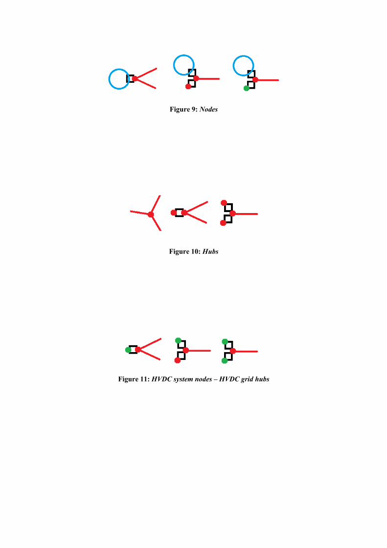
Figure 9: Nodes
Figure 10: Hubs
Figure 11: HVDC system nodes – HVDC grid hubs

Figure 12: Supernodes
Figure 13: Mesh
Figure 14: Controllable meshes

Figure 15: Pseudo-meshes
Figure 16: Two-terminal HVDC systems
Figure 17: Multi-terminal HVDC systems
Figure 18: Back-to-back HVDC systems

Figure 19: Point-to-point HVDC systems
Figure 20: Radial HVDC systems
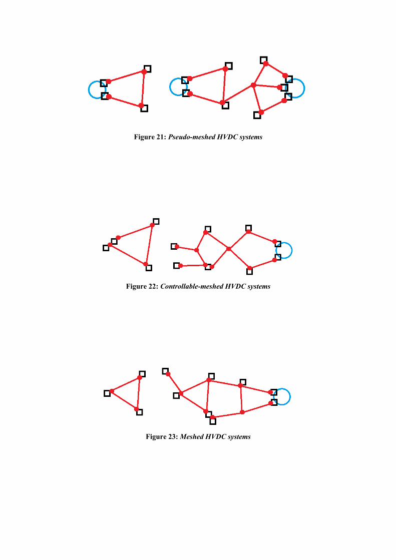
Figure 21: Pseudo-meshed HVDC systems
Figure 22: Controllable-meshed HVDC systems
Figure 23: Meshed HVDC systems

Figure 24: The CIGRE B4 DC Test Grid

9. Tables
Table I: Bus types of the CIGRE B4 DC Test Grid
DC bus Bus type Supernode
Bm-C1 Connection point No
Bm-A1 Connection point Yes
Bb-A1 Node
Bb-C2 Node No
Bb-D1 Node No
Bb-B4 Hub No
Bb-B1 Node No
Bb-B1s Connection point No
Bb-E1 Hub / Node No
Bm-E1 Node No
Bb-B2 Connection point Yes
Bm-B2 Connection point
Bm-B3 Node No
Bm-B5 Connection point No
Bm-F1 Node No
Table II: Loop types of the CIGRE B4 DC Test Grid
Loop type Mesh Controllable-mesh Pseudo-mesh
Involved busses Bb-B1 Bb-B1 Bb-B1
Bb-B4 Bb-A1 Bb-B1s
Bb-A1 Bb-C2 Bb-E1
Bb-B1 Bb-D1 Bm-E1
Bb-E1 Bm-F1
Bb-B1s Bm-B5
Bb-B1 Bm-B3
Bm-B2 Bb-B2
Bb-B4
Bb-B1
Table III: HVDC system properties of the CIGRE B4 DC Test Grid
HVDC system Complexity Topology Size
DCS1 Two-terminal Point-to-point Not large
DCS2 Multi-terminal Radial Not large
DCS3 Multi-terminal Meshed Large