Basics of Interconnected Energy and Power Systems
53
Basics of Interconnected Energy and Power Systems S. S. (Mani) Venkata Alstom Grid Inc. University of Washington Tel: 520-820-8005 (cell) E-mail: [email protected] [email protected] NSF/ECEDHA Education Workshop Atlanta, GA July 10, 2011 7/10/2011 1 © 2009 Copyright S. S. Venkata
Transcript of Basics of Interconnected Energy and Power Systems

Basics of Interconnected Energy and Power Systems
S. S. (Mani) VenkataAlstom Grid Inc.
University of WashingtonTel: 520-820-8005 (cell)
E-mail: [email protected]@comcast.net
NSF/ECEDHA Education WorkshopAtlanta, GAJuly 10, 2011
7/10/2011 1© 2009 Copyright S. S. Venkata

7/10/2011 © 2009 Copyright S. S. Venkata 2
Basics of Interconnected Utility Systems
• Basic technical terms• Integrated (interconnected) power
system• Utility structure• System functions• Performance Indices

7/10/2011 © 2009 Copyright S. S. Venkata 3
Have You Come to “Terms” with the Following?
• Integrated power system• Utility structure• Design• Planning• Operation• Engineers role• Business enterprise• Regulatory/market environment• Standards

7/10/2011 © 2009 Copyright S. S. Venkata 4
Simple “Terms” defined
• Federal Energy Regulatory Commission (FERC): A quasi-independent regulatory agency within the Department of Energy having jurisdiction over interstate electricity sales, wholesale electric rates, hydroelectric licensing, natural gas pricing, oil pipeline rates, and gas pipeline certification.
• North American Electric Reliability Corporation (NERC): FERC approved eight delegation agreements by which NERC will delegate its authority to monitor and enforce compliance with NERC Reliability Standards in the United States to eight Regional Entities, with NERC continuing in an oversight role. FERC certified NERC as the “Electric Reliability Organization (ERO)” for the United States.

7/10/2011 © 2009 Copyright S. S. Venkata 5
Principal “Terms” defined• Independent System Operators (ISO): An
independent, Federally-regulated entity that coordinates regional transmission in a non-discriminatory manner and ensures the safety and reliability of the electric system. Also known as Regional Transmission Operator (RTO)
• Interchange - The agreement among interconnected utilities under which they buy, sell, and exchange power among themselves. This can provide for economy and emergency power supplies.

7/10/2011 © 2009 Copyright S. S. Venkata 6
Mission of Utility• Cost of service (COS) model for rate making was the primary
criterion under regulated environment
• Minimize Total Cost
– Capital cost
– Operations Cost
– Maintenance Cost
– Other associated costs
• Rate making was based on total cost and reasonable return to share holders
• A utility is committed to protecting and securing its systems, facilities, and employees, and ensuring customers continue to receive safe and reliable gas and electric service.

7/10/2011 © 2009 Copyright S. S. Venkata 7
Integrated Power System• Thus far we have examined the major sub-
systems or functions of utility systems
• In this part we will examine how these sub-systems fit together as an integrated or interconnected power system to meet customer expectations
• We will also examine the role of engineers in your utility to design, plan and operate your systems to meet your company objectives.

7/10/2011 © 2009 Copyright S. S. Venkata 8
Vertically Integrated (Regulated) UtilityPlanning and Operational View
Utility
Generation
Distribution
Transmission
Customers
Energy Control
Center (ECC)
EMS Functions
Distribution Control
Center (DCC)
DMS Functions
Other
Utilities
Distribution Control
Center (DCC)
DMS Functions
Operations
Maintenance
Engineering
Design
Construction
Planning

7/10/2011 © 2009 Copyright S. S. Venkata 9
Why Integration?• At the company level, the integration of generation,
transmission and distribution allows cost-effective, reliable and secure power delivery from generating plants to customers.
• Transmission interconnection provides alternate paths in the event of the loss of a plant or a transmission lines (N-1) contingency. This assures better reliability and security.
• The interconnection of an utility with other contiguous utilities via tie-lines enhances the performance indices mentioned above one step further.
7/10/2011 © 2009 Copyright S. S. Venkata 10
Why Integration?
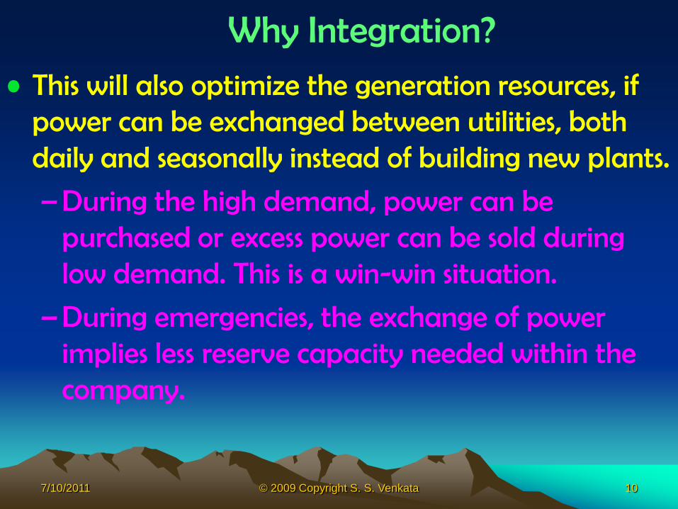
• This will also optimize the generation resources, if power can be exchanged between utilities, both daily and seasonally instead of building new plants.
– During the high demand, power can be purchased or excess power can be sold during low demand. This is a win-win situation.
– During emergencies, the exchange of power implies less reserve capacity needed within the company.

7/10/2011 © 2009 Copyright S. S. Venkata 11
Performance Indices• Power Delivery System Efficiency
• Reliability of supply to customers– SAIFI, SAIDI and CAIDI
• Voltage Regulation
– ± 5 % (114-V to 126-V on 120-V basis)
• Frequency Regulation– ± 0.05 Hz (59.95- to 60.05-Hz on 60-Hz basis)
• Minimum cost of operation– To assure lowest electric bill to consumers
• Security (system and cyber)

7/10/2011 © 2009 Copyright S. S. Venkata 12
Planning, Design and Operations: Philosophical considerations
• Power and energy systems are complex and capital intensive
• Planning, design and operation are very complex process
• Generation, transmission and distribution functions are treated separately form this point of view.
• Multiple objectives and constraints• Changes in customer base are occurring rapidly• Challenges and opportunities to enhance system
performance • How do we adapt to the changes?

7/10/2011 © 2009 Copyright S. S. Venkata 13
Role of System Planning• Identify customer service, system reliability,
and environmental expectations
• Provide consumer end-use and system-use forecasts
• Provide engineering system assessments using electric facility steady state and operational/dynamic models
• Assure additions have a good chance of reaching their planned economic life

7/10/2011 © 2009 Copyright S. S. Venkata 14
Role of System Planning
• Consider economics, reliability, power quality, safety, new technologies, and public acceptance when planning
• Identify right-of-ways and land requirements for future expansion of substations and lines
• Recommend optimal electric system designs and operational practices

7/10/2011 © 2009 Copyright S. S. Venkata 15
Planning Functions• Meet the minimum lead time
• Achieve project objectives
• Keep constraints in mind
• Achieve goals at minimum cost
• Trade off between all of the above

7/10/2011 © 2009 Copyright S. S. Venkata 16
Planning Objectives • Multiple objectives
–Affordable power delivery
–Adequate capacity
–Achieve highest performance levels
•Reliability
•Voltage and power quality
•Efficiency
•Security

7/10/2011 © 2009 Copyright S. S. Venkata 17
Planning Objectives• Short-range planning
– Assure lead time times are met
– Arrive at decisions and specifications for future additions and and/or changes
• Long-range planning
– Be visionary
– Assure that short-range goals are met at a minimum cost
– Evaluation of short-range plans on continuous basis
– Be cognizant of future changes and developments

7/10/2011 © 2009 Copyright S. S. Venkata 18
Planning Objectives
• Normal conditions– System efficiency, reliability, security
– Cost-effective design solutions (minimized total costs)
– Minimum risk investments
– Voltage regulation/load balancing
– Re-configuration of system
• Emergency conditions– Adequate capacity and performance
– Load transfer
– Restoration

7/10/2011 © 2009 Copyright S. S. Venkata 19
Planning Constraints
• Multiple constraints
– Economic (long range total cost minimization)
– Technical (voltage quality, capacity & reliability)
– Societal (total consumer expectations)
– Environmental (UG, dispersed generation)

7/10/2011 © 2009 Copyright S. S. Venkata 20
• Planning time ranges
– Strategic: (>20 years)
– Long Range: (5 to 20 years)
– Short Range: (1 to 4 years)
System Planning Time Ranges

7/10/2011 © 2009 Copyright S. S. Venkata 21
System Planning Time Ranges• Strategic planning methods provide
strategic generation, transmission and distribution direction for long-range infrastructure expansion, operation, and maintenance
• Long Range plans provide direction for short range planning

7/10/2011 © 2009 Copyright S. S. Venkata 22
Engineering and Design
• This is the process of selecting the proper size and ratings of individual components for each of the functions, namely, generation, transmission, substation and distribution.– Each function is treated separately due to its
complex nature – Specifications include voltage, power (va), type
of connections, temperature ranges, Insulation and other relevant parameters
– Attention should to be paid for environmental conditions

7/10/2011 © 2009 Copyright S. S. Venkata 23
Engineering and Design• Standards assist in ensuring equipment reliability, safety and
quality• Different standards available are:
– National Electric Safety Code (NESC): Transmission and Distribution line safety clearances and Right-Of-Way Selection
– National Electric Manufacturers Association (NEMA): Equipment specifications
– American national Standards Institute (ANSI): Legal entity for standards
– Underwriter Laboratories (UL): Customer appliance standards – Institute of Electrical and Electronics Engineers (IEEE): created for
engineering specifications. – International Electrical Commission (IEC): Used by many countries in
the world. IEEE and IEC are cooperating in creating one standard. – National Electric Code (NEC): Safety code for equipment less than
600-V

7/10/2011 © 2009 Copyright S. S. Venkata 24
Operations
• This is the process of ensuring reliable, safe and secure delivery of electric service to customers.
• Transmission and distribution functions are treated separately but coordinated as explained later in this module
• It takes place in real-time with some level automation
• It involves monitoring, protection and control of equipment and system functions

7/10/2011 © 2009 Copyright S. S. Venkata 25
North American Transmission Interconnection Network
Source: NERC

7/10/2011 © 2009 Copyright S. S. Venkata 26
North American Electric Reliability Councils (NERC)
Source: NERC

7/10/2011 © 2009 Copyright S. S. Venkata 27
North American Electric Reliability Councils (NERC)
• RFC – Reliability First • TRE - Electric Reliability
Council of Texas, Inc. • FRCC - Florida Reliability
Coordinating Council• MRO – Mid-American
Reliability Organization
• NPCC - Northeast Power Coordinating Council
• SERC - Southeastern Power Coordinating Council
• SPP - Southwest Power Pool, Inc.
• WECC - Western Electricity Coordinating Council

7/10/2011 © 2009 Copyright S. S. Venkata 28
Reliability First Corporation
Source: http://rfirst.org

7/10/2011 © 2009 Copyright S. S. Venkata 29
The ISO/RTO Council (IRC)
• The ISO/RTO Council (IRC) is comprised of ten Independent System Operators (ISOs) and Regional Transmission Organizations (RTOs) in North America. These ISOs and RTOs serve two-thirds of electricity consumers in the United States and more than 50 percent of Canada's population.
• The IRC works collaboratively to develop effective processes, tools, and methods for improving competitive electricity markets across North America. The IRC’s goal is to balance reliability considerations with market practices, resulting in efficient, robust markets that provide competitive and reliable service to electricity users.

7/10/2011 © 2009 Copyright S. S. Venkata 30
IRC Map

7/10/2011 © 2009 Copyright S. S. Venkata 31
Structure of Operations
Utility
Generation
Distribution
Transmission
Customers
Energy Control
Center (ECC)
EMS Functions
Distribution Control
Center (DCC)
DMS Functions
Other
Utilities
Distribution Control
Center (DCC)
DMS Functions
Operations
Maintenance

7/10/2011 © 2009 Copyright S. S. Venkata 32
Operational Functions at Bulk Level (ECC)
• Energy Control Center (ECC) Operators Functions
–Maintain energy balance under normal condition in real-time
–Take control actions under emergency conditions

7/10/2011 © 2009 Copyright S. S. Venkata 33
Operational Functions at Bulk Level (EMS)
• Energy Management System (EMS)
– Hardware and software systems that enable different applications
• Automatic Generation Control
• Sate Estimation
• Optimum Generation Dispatch
• Unit commitment
• System Restoration

7/10/2011 © 2009 Copyright S. S. Venkata 34
Energy Control Center (ECC)
Source: DMS.org.cy

7/10/2011 © 2009 Copyright S. S. Venkata 35
Operational Functions at Distribution Level (DCC)
• Distribution Control Center (DCC) Operators Functions
–Maintain steady-state operations and dispatch load under normal condition in real-time
–Take proper control actions under emergency conditions

7/10/2011 © 2009 Copyright S. S. Venkata 36
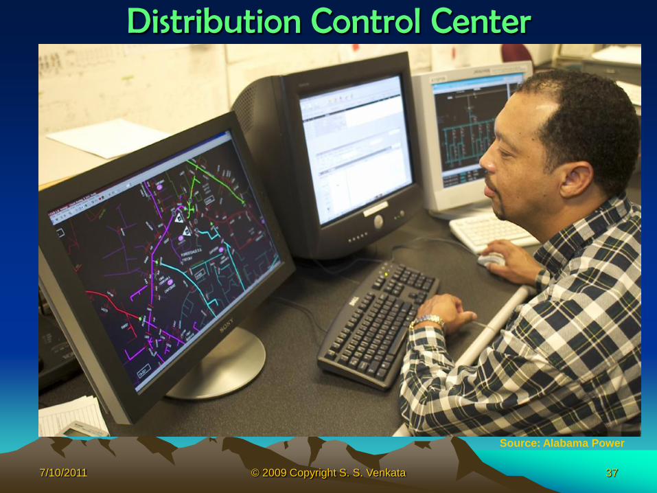
Operational Functions at Distribution Level (DMS)
• Distribution Management System (DMS) – Hardware and software systems that
enable different applications•Voltage/var management and control•System reconfiguration to minimize losses•Demand-side management•Equipment monitoring and control•Asset Management•Fault detection, location, isolation and
system restoration
7/10/2011 © 2009 Copyright S. S. Venkata 37
Distribution Control Center
Source: Alabama Power

7/10/2011 © 2009 Copyright S. S. Venkata 38
Engineers’ Role• Conduct planning, design and operational
planning and operations studies for
– Steady-state time frame
– Dynamic
– Transient
– Implies normal and emergency conditions
• Provide guidance to operators and other technical personnel

7/10/2011 © 2009 Copyright S. S. Venkata 39
Typical Studies Conducted• Power flow analysis
• Short-circuit or fault analysis
• Dynamic and transient analysis
• Transient analysis
• Reliability assessment
• Security analysis
• Power quality assessment
• Economic analysis

7/10/2011 © 2009 Copyright S. S. Venkata 40
System Protection Overview
• Objectives: Prevent damage to equipment and circuits
• Prevent hazards to the public and utility personnel
• Maintain a high level of service by preventing power interruptions
• Minimizing the effects when an interruption occurs
7/10/2011 © 2009 Copyright S. S. Venkata 41
Protection Philosophy
• It is like insurance
• The purpose is to assure– Dependability
– Selectivity
– Sensitivity
– Reliability
– Security

7/10/2011 © 2009 Copyright S. S. Venkata 42
Additional Considerations
• In addition to meet the following objectives
– Basic planning for the system
– Proper phase spacing and conductor insulation
– Vegetation management
– Inspections for other potential problems
– Equipment maintenance

7/10/2011 © 2009 Copyright S. S. Venkata 43
Devices that Need Protection
• Adequate protection must be provided for all types of equipment– Generators– Transformers– Overhead lines– Underground cables]– Capacitors– Voltage regulators– Segments of the system itself

7/10/2011 © 2009 Copyright S. S. Venkata 44
Fault Causes
0 5 10 15 20 25 30
Lightning
Tree contact
Equipment failure
Animals
Wind
Dig-in
Vehicle accident
Ice/snow
Vandalism
Construction activity
Other
Percent of faults by cause
EPRI fault study

7/10/2011 © 2009 Copyright S. S. Venkata 45
Permanent Faults
• One in which damage has occurred from– The cause of the fault or– The fault arc
• Examples– Broken insulator– Broken conductor– Automobile knocking down a pole
• When a permanent fault occurs, the line must be de-energized and a crew is dispatched to repair the damage

7/10/2011 © 2009 Copyright S. S. Venkata 46
Temporary Faults
• Most faults on overhead distribution systems are temporary (70-80%)
• A temporary fault is one whose cause is transitory in nature
• Examples– Brief contact between two conductors
– Tree branch falling across two conductors, then dropping clear
– Bird or small animal that causes a brief arc from the live terminal to ground

7/10/2011 © 2009 Copyright S. S. Venkata 47
Protective Devices
• They are the weakest links installed to protect expensive power devices mentioned earlier
• Single-action fuses
• Automatic circuit reclosers
• Sectionalizers
• Relay-controlled circuit breakers

7/10/2011 © 2009 Copyright S. S. Venkata 48
Protecting Device Coordination
• By conventional definition, when two or more protective devices are applied to a system
–The device nearest the fault on the supply side is the protecting device
–The next nearest is the protected or backup device
Substation Primary (Protecting device)
PrimaryProtected
Device
(Backup)

7/10/2011 © 2009 Copyright S. S. Venkata 49
Blackouts
• This phenomenon occurs when generation demand balance
• The system could lose stability and falls out of step and creating islands of blackouts
• Causes: Tornados, Trees, loss of generation, tie-line interconnection, lack of reactive power support and human error
• Recommendation: Trees, Tools and Training

7/10/2011 © 2009 Copyright S. S. Venkata 50
2003 Blackout Event
When the
cascade was
over at 4:13
pm,
over 50 million
people in the
northeast US
and the
province
of Ontario were
out of power.
Source: IEEE PES

7/10/2011 © 2009 Copyright S. S. Venkata 51
2003 Blackout (Before)
Source: NOAA

7/10/2011 © 2009 Copyright S. S. Venkata 52
2003 Blackout (After)
Source: NOAA

7/10/2011 © 2009 Copyright S. S. Venkata 53
Summary• In this part the purpose of the power
delivery system is introduced.
• System planning and operational functions are described.
• The role of engineers for system performance studies are explained.
What questions do you have?