DEFENSE DOCUMENTATION CENTER · and a time fuze. ASSOCIATED SUBSY ... Mk 263 Mod, 0 SRocket-Thrown...
192
UNCLAISSI FIED *AD406 790 DEFENSE DOCUMENTATION CENTER FOR SCIENTIFIC AND TECHNICAL INFORMATION CAMERON: STATION, ALEXANDRIA, VIRGINIA UNCLASSIFIED
Transcript of DEFENSE DOCUMENTATION CENTER · and a time fuze. ASSOCIATED SUBSY ... Mk 263 Mod, 0 SRocket-Thrown...

UNCLAISSI FIED
*AD406 790
DEFENSE DOCUMENTATION CENTERFOR
SCIENTIFIC AND TECHNICAL INFORMATION
CAMERON: STATION, ALEXANDRIA, VIRGINIA
UNCLASSIFIED

NOTICE: When government or other dravings, speci-
fications or other data are used for any purpose
other than in connection with a definitely related
government procurement operation, the U. S.
Government thereby incurs no responsibility, nor any
obligation whatsoever; and the fact that the Govern-
ment may have forculated, furnished, or in any way
supplied the said drawings, specifications, or other
data is not to be regarded by implication or other-
wise as in any manner licensing the holder or any
other person or corporation, or conveying any rights
or permission to manufacture, use or sell any
patented invention that may in any way be related
thereto.

AA AW DVSO
GADNCIY,'t OK
AAWAICA AMOCAFAAAACoJj4C~AV~jo)

DG-E531-323
FINAL REPORT
TERNE
CONTRACT N 140(122)69961B
Prepared by: Naval Projects Section
Date: 30 April 1963
D C
A~4DIVtISON 1 c oN21W3,/4.1a44. AWIW ANA CORPORATIONTSAS
(i/
| |/

I
DG-ES31-323 Page ii
LIST OF EFFECTIVE PAGES
Title i
Front Matter ii thru viii
Section 1 1-1 thru 1-6
Section 2 2-1 thru 2- 12
Section 3 3-1 thru 3-90
Section 4 4-1 thru 4-27
Appendix A 1 thru 181
Appendix B I thru 4
A i-
S-DGoE531323 Page iiijiiii)
ABSTRACT
This document is the final report of the
system integration effort performed by the
Arma Division, American Bosch Arma
Corporation under Contract N 140(12) 69961B,
in furnishing technical assistance to U. S.
Naval Underwater Ordnance Station to provide
the DE1035 and DE1036 with ASW Weapon
System MK 1 Mod 0. This system combines
the Norwegian TERNE ASW System with
U. S. Fire Control System MK 105. This
report, which fulfills a contractual require-
ment, is a summary of the services and
equipment furnished under the contract.
I

DG-E.531-323 Page iv
CONTENTS
Section Page
I INTRODUCTION 1-11. 1 Purpose 1-11. 2 Background 1- 1
1. 2. 1 OPDEVFOR Evaluation in a Norwegian Ship 1-31.2.2 Prior Contractual Effort 1-3
2 CONTRACT N140(1Z2)69961B 2-12. 1 General 2-12.2 Participants in the Program 2-12.3 Contractual Statement of Work 2-3Z. 4 Contract Modifications 2-6
3 TECHNICAL PERFORMANCE 3-13. 1 Contract Item 1. Signal Converter 3-1
Scope 3-1Performance 3-1End Item Delivery 3-5
3.2 Contract Item 2. Fire Control Switchboard 3-6Scope 3-6Change in Scope 3-6Performance 3-6Switchboard Features 3-8Revisions and Updating of the Final Switchboard
Guidance Plans 3-9Related Documentation 3- 10
3.3 C, ontract Item 3. Torpedo Presetter 3-11Scope 3-11Change in Scope 3-11Performance 3-12End Item Delivery 3-13
3.4 Contract Item 4. OrdAlt Kits for Attack DirectorMK 5 Mod 3 3-14
Scope 3-14Change in Scope 3-14Performance 3-15
'(_

DG-E531-323 Page v
CONTENTS (Continued)
Section Page
3. 5 Contract Item 5. New Design Documentation 3- 17Scope 3-17Performance 3-17Documentation for Signal Converter 3-19Documentation for Torpedo Pre setter 3-2Z
3.6 Contract Item 6. Modified Equipment Documentationfor Attack Director, Item 4 3-25
Scope 3-253.7 Contract Item 7. Norwegian Equipment Documentation 3-26
Scope 3-26Change in Scope 3-27Performance 3-28
End Item Delivery 3-3Z3.8 Contract Item 8. System Documentation 3-34
Scope 3- 34Increase in Scope 3-35Performance 3-36End Item Delivery 3-41
3.9 Contract Item 9. Repair Parts 3-42Scope 3-42Performance 3-42
End Item Delivery 3-423. 10 Contract Item 10. Engineering Services 3-43
3. 10. 1 Contract Item 10a: Liaison 3-43Scope 3-43Performance 3-45
Conference at KV 14- 18 December 1959 3-45Subsequent Meetings at KV 3-47Technical Conferences at Long Beach
Naval Shipyard 3-48Norwegian Documentation Review 3-48Preparation of Recommended Factory
Acceptance Tests 3-493. 10. 2 Contract Item 10b: Installation 3-49
Scope 3-'49
Change in Scope 3-503. 10.2.1 System Integration and Analysis 3-513. 10. 2. 2 Preparation of Function
Schematic Diagrams 3-54S,3. 10.2. 3 System Installation and Checkout 3-58
3. 10.2.4 Training 3-67
DG-7'," ... 23 Page vi
CONTENTS (Continued)
Section Page
3. 10. 3 Contract Item 10c: Missile ComponentEvaluation 3-73
Scope 3-73Clarification of Scope 3-73Performance 3-73Shipboard Test Set 3-79
3. 10. 4 Contract Item 10d: BUWEPS and OPTEVFOREvaluations 3-80
Scope 3-80Performance 3-80
3. 10.5 Contract Item 10e: Related Studies 3-85Scope 3-85Change in Scope 3-85Design Concepts of Launch Range Display
Unit and Slide Rules 3-86Performance 3-88End Item Delivery 3-90
4 PROGRAM PERFORMANCE 4-14. 1 Overall Program Schedule 4-1
4. 2 Engineering Status Meetings 4-54.3 Cost Performance 4-54.4 Program Control 4-64.5 Program Personnel 4-6
Appendix A LIST OF PRINCIPAL CONFERENCES 1
Appendix B REVIEW OF FINAL DOCUMENTATION -
TERNE III EQUIPMENT

"DG-E531-323 Page vii
ILLUSTRATIONS
Figure Page
1-1 Component Equipments of ASW Weapon System MK 1 Mod 0 1-2
2-1 Participants in U. S. TERNE III Program 2-2
Z-Z Summary Chart of Contract Modifications 2-12
3-1 Program Geography 3-44
4-1 Program Performance, Contract N140(1ZZ)69961B (2 Sheets) 4-3
4-2 Expenditure Plot - Signal Converter 4-7
4-3 Expenditure Plot - Fire Control Switchboard 4-8
4-4 Expenditure Plot - Torpedo Presetter 4-9
4-5 Expenditure Plot - OrdAlt Attack Director MK 5 4-10
4-6 Expenditure Plot - Documentation, Signal Converter &Torpedo Presetter 4-11
4-7 Expenditure Plot - Documentation, Norwegian Equipment 4-12
4-8 Expenditure Plot - System Documentation 4-13
4-9 Expenditure Plot - Repair Parts for Converter and Presetter 4-14
4- 10 Expenditure Plot - Engineering Services, Liaison 4- 15
4-11 Expenditure Plot - Engineering Services, Installation(System Integration and Analysis) 4-16
4-12 Expenditure Plot - Engineering Services, Installation(Functional Schematics) 4-17
4-13 Expenditure Plot - Engineering Services, Shipboard Installationand Checkout 4-18

"DG-E531-323 Page viii
ILLUSTRATIONS (Continued)
Figure Page
4-14 Expenditure Plot - Engineering Services, Installation (Training) 4-19
4-15 Expenditure Plot - Engineering Services, Missile Evaluation 4-Z0
4-16 Expenditure Plot - Engineering Services, BUWEPS andOPTEVFOR Evaluation 4-21
4-17 Expenditure Plot - Engineering Services, Related Studies 4-22
4-18 Expenditure Plot - Engineering Services, Launch RangeDisplay Units 4-Z3
4-19 Expenditure Plot - Engineering Services, Slide Rules 4-24
4-20 Contract Summary (Overall) Expenditure Plot 4-25
4-21 Program Manpower Utilization Plot 4-z6
4-Z2 Program Control 4-Z7
~1i

SIDG-E531-323 Page 1-1
Section 1
INTRODUCTION
1.1 PURPOSE.
This report describes the work performed by the Arma Division,American Bosch Arma Corporation, during the period 1 March 1960 to30 April 1963, under Contract N140(IZZ)69961B. Under this contract,Arma provided technical assistance to the U.S. Naval UnderwaterOrdnance Station, Newport, R.I. , for the integration of the NorwegianTerne III ASW system with Fire Control System MK 105 into DE 1035 andDE 1036. The integrated System was designated ASW Weapon SystemMK 1 Mod 0.
The ASW Weapon System MK 1 Mod 0 is described completely inordnance documents NAVWEPS OD 15104, ASW Weapon System.. MK 1"Mod 0, Volume I, and in the System General Data and Maintenance book,Volume II.
Figure 1. 1 shows the component equipments and their basic elementrelationships. The equipments are described in the system data book,Volume II.
1.2 BACKGROUND.
The Terne III ASW System was developed by the Norwegian DefenseResearch Establishment with the assistance of the Royal Norwegian Navyand the United States Mutual Weapons Development Program. The projecthad its inception in Norway in 1954 under MWDP Contract and funding(U. S. Department of State).
It is a complete location-prediction system, intended for use in1000-2000 ton anti-submarine escorts. The Norwegian system consists oftwo independent searchlight sonars, one for search and one for attack, afully automatic predictor and a six-barrelled launcher. The projectilesare rocket-propelled depth charges containing a combined acoustic proximityand a time fuze.

ASSOCIATED SUBSYEQUIPMENT TARGET LOCAUZATION CON
Gyrwmm k4 Stahbiia. Compter Mk 108 Anabog Coam4 Speed Log System. 4 AN/SQS-31b32 Sonar : Position Indic
4 Wind Indicating Equipment AN/SQA-16 (XN-I) Sonar • Firinq Panel
SIndicator Pan
WAttack Direct
4, Bearing Indic
4, Ship's Course
, Target Cours
W Angle Solver
( 4 Torpedo CourMk 3 (2)
4, Autoplotter
4"Navy Equipment " 14-rorpedo DirecPower Distri
Navy Equipment for Torpedoes Mk 44 and VA 46 MK261i Mo
. 4 Navy Equipment for Torpedo Mk 37 Mod I - Il Control Panel
F Terne Equipment -- Firing Panel
A Armo Equipment A Electronic Fr
jjl-]Modified Equipment Mk 50 ModA Control Panel
T-DD Tele-Dynamics Division, IT-DD UBFC
FIGURE 1.1 COMPONENT EQUIPMENTS OF A
* 0

'"WEAPON SYSTEM
SUBSYSTEM 2 SUBSYSTEM 3 SUBSYSTEM 4CONTROL WEAPON DELIVERY WEAPONS
SAnalog Computer Mk 142 Mod0 • Loading House and Loading: Position Indicator Mk 99 Mod: 0 Equipment• Firing Panel Mk 262 Mod 0 • Dud-Jettisoning, Equipment
SRocket-Thrown Depth. Charge,~ Rocket-Thrown. Depth charge. Indicator Panel. Mk 263 Mod, 0 oLuncher Mk 117 Mod 0 Mk 3 Mod O_Atafock Director Mk 5 Mod 3 InTorpedo Tube Mk 32 (2) • Torpedoes.
, Bearing Indicator Mk 22 Mk 44 Mods 0,1,2,3,,4Mk 46 Mod 0, Ship's Course Indicator Mk 6 Torpedo Tube Mk 25 (2)* 4 Torpedo Mk 37 Mod I,Tare Co Depth Charge Release Track 4 Depth Charge Mk 9, Mk 14
-- Angle Solver Mk 17 Mod 2 Mk 94, Torpedo Course Indicator
Mk 3 (2) Not Installed Concurrently With Teme,; Autoplotter Mk 20
P'Torpedo Director Mk 37 Mod lSPower Distribution Panel
MK 261 Mod 0
IMControl: Panel Mk 73 Mod 5Firing Panel Mk 39(Modified)
A Electronic Frequency ConverterMk 50 Mod 0
A Control Panel Mk 264 Mod 0
T-DD UBFC Switchboard,UIPMENTS OF ASW WEAPON SYSTEM MK I MOD 0

fDG-E531-3Z3 Page 1-3
I. 2. 1 OPDEVFOR Evaluation in a Norwegian Ship
A preliminary limited evaluation was conducted by CommanderOperational Development Force on the Terne prototype system from9 September 1958 to 9 October 1958 aboard KNM Balder, a 700-toncoastal escort of the Royal Norwegian Navy, off Key West, Florida.This evaluation generally recognized the potential effectiveness, simplicity,lightweight, and compact design of Terne.
1.Z.Z Prior Contractual Effort
There were two study contracts which preceded ContractN140(lZZ)69961B. These were N140(12Z)686Z4B and N140(I2Z)69074B.
Contract N140(lZ2)686Z4B: Term; Z7 August 1959 - 15 March 1960.In 1959, the Bureau of Ordnance assigned to NUOS under Task Assignment483-534/44009/04070, the task of determining the cost and feasibility ofTerne III for ships of the DE1033 class. Arma provided technical assist-ance to NUOS under Contract N140(12Z)68624B as follows:
"-.U" 0
"Furnish engineering services to investigate the feasibility ofadopting a Norwegian Terne III ASW weapons system aboardvessels of the U.S. Navy. The services to consist of two phases:
(a) Assist in preparation of a study report by the Navy Under-water Ordnance Station relative to DE1033 Class vessels,and
(b) Concluding with written recommendations of what furtherstudies should be performed on the feasibility of adaptingthe Terne III ASW System or components to existing andplanned weapon systems of the U.S. Navy."
The results of this contract were documented in NUOS ConsecutiveReport Z96, "Cost and Feasibility Study of Incorporating Terne III ASWSystem in Vessels of the DE1033 Class," dated 14 September 1959.

DG-E531-323 Page 1-4
The report presented cost and feasibility data for five possiblesystem configurations and recommended for U.S. Navy use, "System Za."System Za consisted of the AN/SQS-4 Sonar (Plus RDT), Terne AttackSonar (for target depth only), Fire Control System MK 105 modified forTerne and the Terne Launcher and Loading Equipments. This system wasrecommended because it
• .. made maximum utilization of proven U.S. equipments.
. .. was a proven system for weapons other than Terne.
was similar to FCS MK 105 in the fleet and therebyminimized logistics and training information.
... provided target depth information.
handled SCB ordnance requirements.
S... should be more easily adaptable to new weapons, such aslong range wire-guided torpedoes.
Contract N140(l2Z)69074B: Term; 30 November 1959 to 17 April 1960.Under Contract N140(122)69074B technical assistance was provided to NUOS to
"... specifically define the scope of engineering design andtechnical development necessary to permit the incorporation ofthe Terne III ASW System (from Kongsberg Vaapenfabrikk, Norway)to implement the designated 'System Za2 aboard the DE1035 andDE1036. The engineering services shall further be utilized to pro-vide assistance to Naval Underwater Ordnance Station in preparingthe following reports
... Phase Plan
... Technical Development Plan
.. . Documentation Survey"
1'

"DG-E531.•323 Page 1-5
Phase Plan. The Phase Plan, documented as "Terne III MissileProgram Phasing Schedule" (BuOrd Task Assignments No. 417064/42Z02/01070 and 60070) defined the detailed scheduling required for the completeprogram including conduct of studies, equipment procurement, installa-tion and all related documentation. The Phase Plan was delivered9 December 1959.
At a conference at Kongsberg Vaapenfabrikk (KV), Norway, 14-18December 1959; an alternative system was proposed by KV using theTerne Fire Control Computer instead of Computer MK 68, Computer MK 59and Power Supply MK 88 of "System Za". The use of the Terne computerhad not been previously recommended in "System Za" mainly because of itsfunctional incompatibility with the Attack Director MK 5. During the con-ference, it was disclosed that the Terne computer had already been modi-fied by the Norwegians so that, with relatively simple changes, it could beused with proper converters directly with the Attack Director MK 5. Theresultant system, a "modified System Za," became the system about whichthe Detailed Technical Plan and Documentation Survey were prepared.
Technical Development Plan. This document indicated the proposedtechniques, annual funding and time phasing for the development and integra•-tion of System 2a (as modified at the December 1959 conference). Thedocument was prepared in accordance with ONR Instruction 3910. 1,17 December 1957; "Instructions for Preparation of an R & D TechnicalDevelopment Plan. "
The Technical Development Plan (TDP) was based on CNONTX 171953Z, November 1959, which amended SCB Project 131 so thatthe Hedgehog ASW weapon was removed and replaced by the NorwegianTerne III ASW weapon. This weapon system was originally designated asWeapon System W-113. The TDP set forth the performance characteristicsand effectivity of the weapon system and presented time schedules andfunding requirements to
•... provide Weapon System Development Coordination
... procure Norwegian components

DG-E531I-3Z3 Page .1-6
define requirements and engineer for service application;the equipments and modifications necessary to integrateNorwegian components
provide engineering assistance for installation, checkout,OPTEVFOR evaluation and bridge-the-gap training.
The schedules set forth the activity responsible for system develop-ment, funding requirements for development, equipment procurement,documentation, installation, field and shop tests and personnel training.The TDP also described the system operation, the complete develop-mental aspects, reviewed the characteristics of associated systems, andset up manning requirements. The TDP was completed and delivered on24 February 1-960 1o NUOS.
Documentation Survey. The third task under this contract, prepara-tion of the documentation survey, was completed 13 January, 1960 andresulted in a document entitled; "Recommended Documentation for theWeapon System W-113 Aboard the DE1035 and 1036 Vessels." It containsthe documentation requirement for each item to be procured for WeaponSystem W-113. It prescribed the minimum documentation for items to beprocured from KV. This minimum documentation was limited to thatrequired for equipment installation and maintenance. This document alsocontains a "Summary of Budgetary Cost of Documentation Recommendedfor ASW Weapon System W-113 Aboard the DE1035 and DE1036 Vessels."
In addition to these three items of documentation required by thiscontract; at the request of NUOS a document entitled "Technical Requirementsfor Procuring of Norwegian Components for Weapon System W-.113 (TerneIII ASW System)" was prepared and furnished to NUOS on 14 January 1960.It was later revised as a result of visit by NUOS to NPO, London, England;with final copy dated 26 January 1960, forwarded to NUOS. The finaldocument prescribed the number of each type of Norwegian equipment to beprocured from KV. It specified the modifications required to each equip-ment to render it satisfactory for use on the DE1035 and DE1036 vessels.It also contained a section outlining the final documentation to be suppliedby KV for each equipment.

4j-
DG-E531-3Z3 Page Z-1
Section, Z
CONTRACT N140(!ZZ) 69961B
Z. I GENERAL
This section of the report describes the contract requirements andthe related modifications.
In response to NPO Brooklyn RFP Q7463, Arma proposal letterJN-A431-C 581 of Z4 March 1960 submitted a technical proposal, "SystemIntegration for Weapon System W-113, " Arma Document A60-7. Contractnegotiations began 1 June 1960 and concluded when the fully executed con-tract N140(IZ2)69961B was received in September 1960, with provisions forauthorization of costs incurred beginning 1 March 1960. For funding pur-poses, the work statement was set forth in two phases, Phase I and PhaseII.(Items covered by Phase I are indicated by an asterisk in the list of items ofthe Statement of Work, paragraph 2. 3. Phase II items are indicated by adouble asterisk.)
Authorization was received 23 June 1960 (NPO Brooklyn letter P3:dbN140(1ZZ)69961B) to commence Phase 1 and at which time an option forPhase II was indicated also. The Phase II option was exercised by theGovernment by Contract Modification 1, dated Z November 1960.
2. Z PARTICIPANTS IN THE PROGRAM
The principal participants in the program are shown on the chart,Figure 2-1.
Program management was under cognizance of the Naval Under-water Ordnance Station. Mr. Leo F. Risko was Program Manager, who was succeededlater by Mr. F.W. Kamph. Mr. R. Frey, Code 603, was Project Managerat BuShips, with Mr. D. Wagner, Code 689C, having cognizance over theTERNE sonar and Mr. E. Garrison, Code 665F, over the UBFC switchboardfor the DE 1035 and DE 1036 vessels. Installation design at Long BeachNaval Shipyard was under cognizance of Mr. J.R. Cole, Project Manager;with the system checkout under cognizance of Chief Ordnance Engineer,Mr. Logan Colby.

BUMEPS
NUOS -
NWL NTS' KONOSBERO
DAHLGREN KEYPORT VAAPEN-
VA WASHFARKA
FIGURE 2.1 PARTICIPANTS

2-2
DIRECTIVES
-BUSHIPSOIIYR
Iw -11AH 0
N- B~A1I 011036(K AMERICAN BOSCHARMA 'CORP' SHPARD
PARTICIPANTS IN U.S. TERNE Xl PROGRAM

DG-E531-323 Page 2-3
"The TERNE equipments were furnished by Kongsberg Vaapenfabrikk,Norway, under Contract NG 2558-2478. Work at KV was under the directionof Mr. B. Hurlen, the Technical Director; Captain Frihagen, Contracts; andMr. K. Seim, Engineering. Under this contract, the Norwegians also pro-vided technical assistance during the shipboard installation and evaluation.
Responsibility at Arma for technical assistance to NUOS for systemintegration, documentation, and for installation and evaluation support wasunder the cognizance of Mr. E. R. Behn, Section Head of Naval Projects.The Tele-Dynamics Division of the American Bosch Arma Corporation wasresponsible under BuShips Contract NObs 78906 for design and fabrication oftwo underwater battery switchboards f or the integrated system.
2.3 CONTRACTUAL STATEMENT OF WORK
Contract N140(122) 69961B provided for the performance of suchresearch, design, development and engineering, services and for the manu-facture and furnishing of such equipments and documentation required by theU.S. Navy Underwater Ordnance Station, Newport, Rhode Island, to installthe Norwegian Terne III Weapon System on U. S. Navy Vessels DE 1035 andDE 1036; and integrating it with the existing weapon complement and FireControl System MK 105 Mod 3.
The services and equipments to be furnished were to be in accord-ance with the U.S. Naval Undez .Tater Ordnance Station Specification titled"Description and Requirements for U.S. Equipments and Services for SmallShip ASW Weapons System (TERNE) W-l13", dated 1 February 1960 andAddendum I thereto; and Arma Division's Technical Proposal, DocumentA60-7 dated 29 February 1960, as amended by the formal contract.
The equipment and services to be furnished are itemized as in thecontract, as follows:
I

DG-E531-323 Page 2-4
Contract Item 1. * Signal Converter, quantity 2 each
Task: Define requirements and engineer for serviceapplications.
(Equipment designation became ElectronicFrequency Converter MK 50 Mod 0)
Contract Item 2. * Fire Control Switchboard
Task: Define requirements only.
(Equipment design and fabrication to be accom-plished under BUSHIPS Contract NObs 78906 byTele-Dynamics Division of the American BoschArma Corporation).
Contract Item 3. * Torpedo Presetter, quantity 2 each
Task: Engineer for service application.
(Equipment designation became Control PanelMK 264 Mod 0)
Contract Item 4. * Ordalt Kits for Attack Director MK 5 Mod 3,quantity 2 each
Task: Define requirements and engineer for service
application.
Contract Item 5. * New Design Equipment Documentation, quantity 1set each. (End-Delivery: 300 printed copies)
Task: a. For Signal Converter
b. For Torpedo Presetter
*Phase I (See Para. 2. 1)

DG-E531-323 Page 2-5
Contract Item 6. ** Modified Equipment Documentation for AttackDirector, quantity 1 set. (End-Delivery: 300printed copies)
Task: Preparation of Ordalts.
Contract Item 7. Norwegian Equipment Documentation, quantity1 set, (End-Delivery: 300 printed copies)
Task: Preparation of instruction books for the Norwegianmanufactured equipments.
Contract Item 8. * System Documentation, quantity 1 set, (End-Delivery: 300 printed copies)
Task: Preparation of instruction books for the overallweapon system.
Contract Item 9. * Repair Parts
a. Signal Converter, Item 1, quantity 2 sets.
b. Torpedo Presetter, item 3, quantity 2 sets.
Task: Furnish 2 sets each of repair parts for SignalConverter and Torpedo Presetter.
Contract Item 10. Engineering Services, as required
Task: Furnish services in the areas of:
a. Liaison*
b. Instal lation**
c. Missile Component Evaluation*
d. BUWEPS and OPTEVFOR Evaluation**
e. Related Studies.:'**Evaluate increased performance of U.S. Ordnancethrough use of Terne IlI Depth Sonar. Determine ¶
optimum vessel size for Terne III system.* Phase I** Phase II (See Para, Z. 1)

DG-E531-323 Page 2-6
2.4 CONTRACT MODIFICATIONS
During the term of Contract N140(122)69961B, there were 21 modifi-cations. The modifications and related contract items are shown on thesummary chart, figure 2-2. The effect of the modifications on the contractualstatement of work is presented in the following tabulation.
Contract Contract ItemsMod. Date Affected Description
1 11/2/60 4; 6; 1Oa, b, d Contract modified to provide for per-formance of Phase II in accordance withcontract requirements, as if the optionhad been exercised. It also set forth thatCQearance NY 10400.2, Serial 01017 of6 June 1960 applied to the contract.(NUOS letter Del-T:TAL:cal-8510 Terneof 10 November 1960 clarified SecurityCheck List, Form DD254, Item 19,Tests; as meaning the OPTEVFOR testsand not the equipment operating tests.)
2 11/9/60 lOc Limited Arma effort in the missile andfuze evaluation. This modification waslater withdrawn by NPO Bkl yn letterC-1l:jw-Nl40(lZ2)69961B of 16 December1960, as result of a conference with NUOSon 22 November 1960, and NUOS letterDel-T:TAL;cal, 8510/Terne, 8 December1960; which gave approval to an Armadocument delineating the Arma effortswith regard to missife and fuze (laboratory)evaluation, and stated since this wouldclarify the contractual statement; contractmodifications would not be required.
3 11/10/60 5 Added Arma interpretation of MilitarySpecification MIL-D-70327, Drawings,Engineering and Associated Lists to the
contract specifications (Arma Document521-000-898).

f,4
DG-E531-323 Page 2-7
Contract Contract ItemsMod. Date Affected Description
4 2/23/61 7 Revised titles of Terne Equipment In-struction Books and added a requirementto prepare documentation for the TerneIII Power Panel (Power DistributionPanel MK 261 Mod 0). Also it noted that"Test Equipment for Terne Fuze" in-struction book title would be determi nedafter hardware availability.
5 3/28/61 l0e Directed Arma to perform a study of over-the-side torpedo launching requirementsto: determine optimum launching doctrinefor Torpedoes Mk 44 and 46; delineate thedisplays and/or computation required to"utili ze thi s doctrine; and prepare prelim -inary desi gn specifications for modifica-tions to existing surface ship fire controlsystems to implement the launching doc-trine.
6 4/3/61 3, 7 Added a task to Define Requirements -
for the Torpedo Presetter. Also,addedan Arma Engineering review of TerneEquipment Instruction Book manuscriptsprior to final submission.
7 4/3/61 2,8, 10 Provided for a study of the requirementsfor including the Torpedo MK 37 Mod 1,the installation of Torpedo Tube MK 25and associated loading equipment, and mod-ifications to FCS MK 105 for Terne III onDE 1035 and DE 1036, and also effect ofTorpedo MK 37 Mod 1 on weapon systeminstalled on DE 1033 and DE 1034. AmendedScope of Contract to add "The existing wea-
4 pon system complement on U.S. NavyVessels DE 1'035 and DE 1036 shall include

DG-E531-323 Page 2-8
Contract Contract ItemsMod Date Affected Description
7 (Cont'd.) Torpedo MK 37 Mod 1. Documentationrequired to be furnished under the terms ofthe contract shall provide for installationof the equipment required for this torpedoconcurrently with the TER.NE III weaponsystem installation.
Note: Modification 7 was first amended byModification 12, and then by Modification15, to provide for clarification requestedby Arma.
8 4/3/61 4,6 Added "Class 1" to Record Plans and LDs.Deleted requirements for modifi cation ofAttack Director Mk 5 Mod 3 and held inabeyance ORDALTS to Attack DirectorMK 5 Mod 5 pending further study. This
amendment also changed cognizance of 'inspection and acceptance from BUWEPS
RES REP ARMA TO INSMAT, Garden City.
9 7/19/61 7,8, 10 Authorized Arma to revise system func-tional drawing, cabling diagrams, functionalschematic drawings, and handbooks inaccordance with drawings received fromKV at conference in June 1961; KV ltrU/75, 2/61/TH/GA of 7 July 196i; and finalrevised drawings of AN/SQA-16 sonar transmitter/receiver and transformer box.
10 8/17/61 4, 10e Decreased funding under Phase I due to de-letions of Modification No. 8, and increasedfunding under Phase II as a result of changesdirected by Modification No. 5, resultingin a net increase of $20, 660 for the totalestimated cost under the contract. Alsoadded requirement for a short form ORDALTproviding smoothed sonar range fromAttack Director MK 5 to the Terne ASWSystem.

DG-E531-323 Page 2-9
Contract Contract ItemsMod Date Affected Description
11 8/17/61 All items Time of Performance revised to that pro-
posed by Arma ltr JFMcC-A453-CG1ZZof 28 February 1961 in lieu of originalschedule submitted with the TechnicalProposal (Arma Document A60-7). In'addition, neiw torpl'etion'dates wereestablished for "'time of performance''of the Related Studies task to allow forcompletion of related but more urgentwork. It is to be noted that Modification11 was concerned with the overall pro-gram schedule and contract "time ofperformance" and it is reflected in theprogram performance, Figure 4-1.
12 8/18/61 10b This modification amended Modifi cation7 to delete the study report requirementfor including a description of the tech-nical modifications and problems relatingto the physical installation of TorpedoTube MK 25 and associated loading equip-ment.
13 9/1/61 l0e Gav e technical direction to design, de-velop and manufacture two prototypeLaunch Range Display Units and Z5 Sim-
plified Torpedo Launch Range Slide Rules.
14 9/29/61 8, 10b This modification directed that all refer-ences to depth charges be deleted fromsystem documentation, as the existingweapon complement on DE 1035 and 1036shall not include depth charges.
15 10/30/61 1Ob This modification withdrew modification 12in its entirety to restate the intent of Mod-ification 7 and to define the GFM to befurnished.

DG,,E531-323 Page Z-.10
Contract Contract ItemsMod. Date Affected Description
16 3/15/62 7, 10a,b Decreased funding to correspond with com-plete deletion of remaining efforts for mod-ification of attack directors. Al so due toincompleteness of GFM, an increased effortin the areas of Norwegian equipment doc-umentati on, liaison, and installation wasfunded, resulting in an overall total esti-mated cost increase of $44, 779.
17 4/3/62 5, 10e Deleted requirement for engineering studyon application of Terne III mi ssile to fleettype vessels. Also reduced requirementsfor quantity of torpedo presetter (ControlPanel MK 264 Mod 0) instruction booksfrom 300 to 20, resulting in a decrease incontract funding.
18 5/17/62 5 Provided for deletion of the requirementfor authenticated drawings of ElectronicFrequency Converter MK 50 Mod 0 underPhase I, Item 5. Also decreased contractfunding and fixed fee.
19 8/29/62 5,7 Provided for furnishing 6 copies each ofpreliminary instruction books of Norwegianequipments and Signal Converter for ad-vance information and decreased the totalnumber of books to be delivered as an enditem from 300 to 250 copies (except forOP 3028 - 260 copies), (The reductioninquan-tity was equivalent to the cost of producingsix copies, with no change in contract funding)
(

DG--E531-3Z3 Page 2-11
Contract Contract ItemsMod. Date Affected Description
20 1Z/14/62 5,7,8 Clarified titles of instruction book de-liverable end items and amended theContract Schedule delivery dates for theremaining designated documentation asfollows:
NAVWEPS OP 3034 - Launcher, LoadingHouse Equipment Vol. I, II. (Deliveryprior to 1/4/63).
NAVSHIPS 94181 - Sonar Depth Determin-ing Group AN/SQA-16(XN-1) (Deliveryprior to 1/4/63).
NAVWEPS OD 15104 - ASW Weapon Sys-tem Mk 1 Mod 0, Vols. IL II plus Adden-dum, III, IV. (Delivery prior to 3/8/63).
Stated that requirement for instructionbook for fuze test equipment (Item 7.i)'was still pending.
21 1/31/63 7 Corrected title for NAVSHIPS 94181AN/SQA-16 (XN-1) Sonar InstructionBook as stated in Modification 20. Alsoestablished that delivery of Item 7. i wouldbe as "Mutually agreed upon when workon Item 7.i is started."

DG-E531 -323 Page Z-1Z
00
N x 00'-4x
-41U -44
-+4
z
x 0
0 0X- 4J W 4XýJ 4j -% k0
Id ;.4 (1
,4 0) -
( dN d- J 4 b 14N
M,~4 Z
P4 0 0
41~~~ -4bfl0 Y, -

SDG-E531-323 Page 3-1
Section 3
TECHNICAL PERFORMANCE
This section summarizes the work accomplished under the contract,for each contract item. The summary also includes a statement of thescope of the task, and a review of the effect of pertinent contract modifica-tions.
3. 1 CONTRACT ITEM 1. SIGNAL CONVERTER'
(Equipment nomenclature has been assigned as Electronic FrequencyConverter Mk 50 Mod 0.)
SCOPE: Define Requirements and Engineer for Service Application.
This effort required the design, development and manufac-ture of two prototype frequency converters to permit data transmission be-tween the Norwegian and U. S. equipments where these equipments werenot compatible with regard to signal transmission.
1) Define Requirements Task
Under this task a design approval package, functionaldiagram and physical configuration layout consistent with available ship-board space, design and specification requirements were prepared,submitted, and approved by NUOS.
2) Engineer for Service Application Task
Under this task two prototype frequency converters weredeveloped, fabricated and acceptance tested. These units were deliveredto Long Beach Naval Shipyard and installed on DE 1035 and DE 1036 as partof ASW Weapon System Mk 1 Mod 0.
PERFORMIANCE:
1) Design Configuration
The frequency converter design criteria were based onstudy of the functional requirements for the integration of Terne III, Item10a. The following system functions required conversion:

t DG-E53 1-323 Page 3-2
Symbol Function Signal Received Signal Transmitted
Hq Target Depth 400 cycle scaled 60 cycle synchro signal
voltage @ Z0mv/yd @ 3,000 ft/rev
Sonar depression angle60 cycle synchro signalat 360*/rev (Eq)
Co Own Course 60 cycle synchro 400 cycle synchro signal
signal @ 36 0*/rev @ 360*/rev
Rq Slant Range 60 cycle synchro 400 cycle scaled
signal at 72K and voltage at 20 mv/yd
2K yd/rev (pot~ntiometer)
400 cycle scaled volt-
age at 20 mv/yd 0. 1%linearity (vernistat)
Swa Apparent Wind 60 cycle synchro 400 cycle synchro
Speed signal at 100 kt/rev signal at 100 kt/rev
Bwa Apparent Wind 60 cycle synchro 400 cycle synchro
Direction signal at 360 /rev signal at 360*/rev
cBrq Generated Target 60 cycle synchro 400 cycle synchro
Relative Bearing signal at 360* and resolver signal at
100/rev 360*/rev
N Pitch 60 cycle synchro 400 cycle synchro
signal at 180" and signal at 120*/rev
10"/rev
DG-E531-323 Page 3-3
Symbol Function Signal Received Signal Transmitted
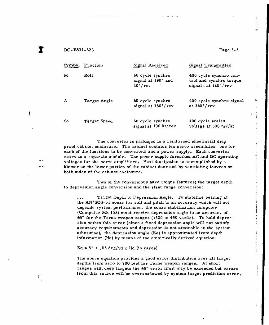
M Roll 60 cycle synchro 400 cycle synchro con-signal at 1800 and trol and synchro torque10*/rev signals at lZ00/rev
A Target Angle 60 cycle synchro 400 cycle synchro signalsignal at 360*/rev. at 360'/rev
So Target Speed 60 cycle synchro 400 cycle scaledsignal at 100 kt/ rev voltage at 500 mv/kt
The converter is packaged in a reinforced sheetmetal dripproof cabinet enclosure. The cabinet contains ten servo assemblies, one foreach of the functions to be converted; and a power supply. Each converterservo is a separate module. The power supply furnishes. AC and DC operatingvoltages for the servo amplifiers. Heat dissipation is accomplished by ablower on the lower portion of the cabinet door and by ventilating louvres onboth sides of the cabinet enclosure.
Two of the conversions have unique features; the target depthto depression angle conversion and the slant range conversion:
Target Depth to Depression Angle. To stabilize bearing atthe AN/SQS-31 sonar for roll and pitch to an accuracy which will notdegrade system performance, the sonar stabilization computer(Computer Mk 108) must receive depression angle to an accuracy of*50 for the Terne weapon ranges (1500 to 450 yards). To hold depres-sion within this error (since a fixed depression angle will not satisfyaccuracy requirements and depression is not attainable in the systemotherwise), the depression angle (Eq) is approximated from depthinformation (Hq) by means of the empirically derived equation:
Eq = 50 + .05 deg/yd x Hq (in yards)
The above equation provides a good error distribution over all targetdepths from zero to 700 feet for Terne weapon ranges. At shortranges with deep targets the *50 error limit may be exceeded but errorsfrom this source will be overshadowed by system target prediction error,

DG-E5*31-323 Page 3-4
The equation was instrumented by means of a gear train and a synchroposition offset in the depth conversion servo.
... Slant Range. The Terne depth sonar computes horizontalrange from target depth and an input of sonar slant range for use in theTerne weapon prediction solution. Therefore conversion of sonar slantrange from a synchro order to a scalor quantity is required. The AttackDirector Mk 5, however, has smoothed slant range output as a highspeed (2, 000 yds. per turn) signal only. The converter servo is instru-mented to receive attack director computed horizontal range as a lowspeed (72 Kyds. per turn) signal although the high speed slant range andlow speed horizontal range will not, in general, be synchronized. Thisis permissible since the purpose of the low speed signal is to keep theservo in its stops at ranges greater than Z, 000 yards, otherwise theservo could synchronize to false readings. With reduction in gain,accomplished by an external transfer circuit which prevents the lowspeed signal from governing the servo unless the error signal representsmore than 150 yards, the servo will synchronize to the high speed slantrange signal with suitable accuracy and stability.
"2) GFM Utilization. The converter unit design included Navystandard, Government-furnished amplifier and rotating components in ac--cordance with Arma Proposal A60-7. The use of these standard parts servedto reduce the number of new items to be added to Federal stock lists and alsoenabled the converters to be produced at minimum cost. The GFM utilized inthe converter equipment is listed below for the two units:
Description Quantity
Synchro - 15CT6a ZZSynchro - 15CX4b 12Synchro - 15TR4C 2Synchro - 15CX6XN 2Synchro - 23TRX6a 4Synchro - 23CX6a 2Amplifier - 1625248 14
Amplifier - 1625247 2
Spare Parts (GFM) furnished U. S. Navy:
Description Quantity
_ Amplifier - 1625248 4
Amplifier - 1625247 2

DG-E53 1-323 Page 3-5
3) Related Documentation
The converter preliminary design approval package wassubmitted to NUOS for review by Arma letter JFMcC-A453- C5944 of 12October 1960. On 9 December 1960, a preliminary design approval conferencewas held to review the comments contained in NUOS letter Del-T:TAL:akm-8510/TERNE of 1 December 1960. The agreements reached at this meetingwere incorporated into the final design approval package which was submittedby Arma letter JFMcC-A453-C1094 of 27 February 1961. Final designapproval was received by NUOS letter DeZa- h:REB:jm-8200 of 20 March 1961.The Provisioning Parts List, submitted by Arma letter JEMcC-A453-C4549of 4 August 1961, was approved by NUOS letter Del-T:LFR:akm-8510/TERNEof 20 September 1961. All other documentation including drawings was pre-pared and furnished in accordance with Contract Item 5, New Design Documenta-tion. The instruction book title is NAVWEPS OP 3028, Electronic FrequencyConverter MK 50 Mod 0; Description, Operation and Maintenance.
END ITEM DELIVERY: The first converter unit was delivered inJuly 1961, and the second unit in August 1961. Both units were shipped toLong Beach Naval Shipyard for shipboard installation; the first on DD250 -
Partial Shipment No. 3, dated 13 July 1961, by GBL No. A-2998833 and thesecond on DDZ50 - Partial Shipment No. 4, dated 14 August 1963, by GBLNo. A-2998969.
DG-E531-3Z3 Page 3-6
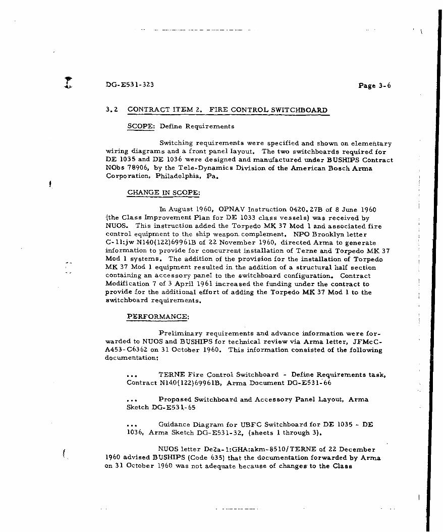
3. Z CONTRACT ITEM 2. FIRE CONTROL SWITCHBOARD
SCOPE: Define Requirements
Switching requirements were specified and shown on elementarywiring diagrams and a front panel layout. The two switchboards required forDE 1035 and DE 1036 were designed and manufactured under BUSHIPS ContractNObs 78906, by the Tele-Dynamics Division of the American Bosch ArmaCorporation, Philadelphia, Pa.
CHANGE IN SCOPE:
In August 1960, OPNAV Instruction 04Z0. 27B of 8 June 1960(the Class Improvement Plan for DE 1033 class vessels) was received byNUOS. This instruction added the Torpedo MK 37 Mod 1 and associated firecontrol equipment to the ship weapon. complement. NPO Brooklyn letterC- ll:jw N140(122)69961B of ZZ November 1960, directed Arma to generateinformation to provide for concurrent installation of Terne and Torpedo MK 37Mod 1 systems. The addition of the provision for the installation of TorpedoMK 37 Mod 1 equipment resulted in the addition of a structural half section"containing an accessory panel to the switchboard configuration. ContractModification 7 of 3 April 1961 increased the funding under the contract toprovide for the additional effort of adding the Torpedo MK 37 Mod I to theswitchboard requirements.
PERFORMANCE:
Preliminary requirements and advance information were for-warded to NUOS and BUSHIPS for technical review via Arma letter, JFMcC-A453-C636Z on 31 October 1960. This information consisted of the followingdocumentation:
... TERNE Fire Control Switchboard - Define Requirements task,Contract N140(lZ12)6996 IB, Arma Document DG-E53 I- 66
... Proposed Switchboard and Accessory Panel Layout, ArmaSketch DG-E53 1-65
• .. Guidance Diagram for UBFC Switchboard for DE 1035 - DE1036, Arrna Sketch DG-E531-3Z, (sheets I through 3).
NUOS letter DeZa- l:GHA:akxn-8510/TERNE of 2Z December1960 advised BUSHIPS (Code 635) that the documentation forwarded by Arrnaon 31 October 1960 was not adequate because of changes to the Class

DG-E53 1-323 Page 3-7
Improvement Plans for DE 1033 class vessels, OPNAV INST 04720. Z7B. Thisletter also stated that NUOS was initiating a change to the Arma contract toallow for the inclusion of Torpedo MK 37 Mod 1 in the switchboard require-ments, and it recommended that BUSHIPS authorize Tele-Dynamics to proceedwith the fabrication of a basic switchboard which would provide space forthe additional switching requirements. The letter established a date of 15March 1961 for delivery of the final switchboard requirements to Tele-Dynamics.
During Tele-Dynamics and Arma conference on 26 January 1961,T-DDwas advised as to the number of additional switchboard components(switches, lights, overload indicators, etc.) that would be required to accomo-date the Torpedo MK 37 Mod 1 equipments. This was followed by a conferenceon 15 February 1961 to discuss switchboard layout and circuit requirements.
BUSHIPS letter DE 1035/9710, Ser. 665F-18, of 24 February1961 advised NUOS that T-DD had been instructed to provide space in theDE 1035 and DE 1036 switchboards for Torpedo MK 37 Mod 1 requirements andrequested that NUOS expedite the dissemination of the design data.
"Arma letter JFMcC-A453-CII86 of 1 March 1961 forwarded- - preliminary copies of switchboard guidance drawings for ASW Weapon
System MK 1 Mod 0, Arma document DG-E531-96 (sheets I through 4) to Tele-Dynamics. These plans provided for TERNE, Over-the-Side Torpedoes, andTorpedo MK 37 Mod 1 weapons equipment switching requirements.
On 13 and 14 March 1961, the switchboard guidance plans forDE 1035 and DE 1036, Arma document DG-E531-96 (sheets I through 4ý andthe proposed switchboard faceplate format, T-DD sketch 00057-304 werereviewed by BUSHIPS, Code 665f, at a meeting at BUSHIPS attended by repre-sentatives from BUWEPS, NUOS, T-DD, LBNS, and Arma. The drawingswere approved subject to minor changes requested by BUSHIPS and the assign-ment of sonar lead designations.
On 21 March 1961, Arma visited BUSHIPS, Code 6 89c, toresolve assignment of sonar lead designations to be added to the switchboardguidance plans.
The final UBFC Switchboard requirements on Form DD 250 -
Contract (Partial Shipment No. 1) were forwarded to NUOS, BUSHIPS (Codes635 and 665) and Tele-Dynamics by Arma letter JFMcC-A453-C1806 of27 March 1961. The plans included switching for control of equipment associatedwith the TERNE weapon, Over-the-Side Torpedoes MK 44 and MK 46, and
( Torpedo MK 37 Mod 1. Copies of these plans were hand delivered to LBNSYDon 28 March 1961 and to Tele-Dynamics on 24 March 1961. The plans consisted

DG-E531-323 Page 3-8
of the following:
.... Final Guidance Plans for ASW Weapon System MK 1 Mod 0 UBFCSwitchboard, Elementary Wiring Diagram, Arma Document DG-E531-96,Rev. A
Supplementary Switchboard Information, Arma DocumentDG-E53 1- 10 1.
SWITCHBOARD FEATURES
The Final Guidance Plans and Supplementary SwitchboardInformation specified the design requirements for:
Functional mode selective switching - OFF, TERNE TEST,TERNE, TORPEDO TUBE MK 25, TORPEDO TEST, and BOTH.
Equipment action cut-out switching.
I Buss Testing (megger, frequency, and voltage).
Fixed test signals in the TEST modes for system checks.
Fusing and overload provisions.
... Indicator lamps.
Operational control of the integrated system is provided by ahand-operated Mode Selector switch via automatic JR-type switches andmagnetic power contactors.
Action cut-out switching was provided for the Attack DirectorMK 5, Converter, MK 50 Control Panel MK 264 (torpedo presetter), ShipsCourse Indicator MK 6 Mod 5, Indicator Panel MK 263, Bearing Indicator MK22, Computer MK 108 Mod 1, the sonar alarm circuits, the AN/SQS-31 (oir 3Z)sonar and the sonar trainer, as well as the equipments for firing Torpedo Mk 37Mod I. The Converter MK 50 action cut-out switching capability was functionallyseparated by assigning TERNE computer functions to one switch control andTERNE depth sonar to another switch. This permits cut-out of the computerfunctions of the converter while continuing availability of depth sonar functionsfrom the converter.
Indicator lamps on the switchboard and on an associated ControlIndicator Panel were provided to show availability of power and external synchro

DG-E531-323 Page 3-9
signals, TERNE circuit breaker trip indication, sonar on target status, andSystem Mode Selector switch position.
Fusing of all power cirgiits originating within the switchboardwas employed to insure protection against circuit shorting or overloading ofship-cabling. Fusing was also provided for all synchro excitation poweroriginating external to the switchboard. Over-load indicators were used foronly those synchro transmission circuits having a torque receiver as a load.
Switching was also provided for controlling the Power Distribu-tion Panel MK Z61 Mod 0 power contactors for Sonar Depth Determining GroupAN/SQA- 16(XN- 1) and Analog Computer MK 142 Mod 0. Trip indicationlamps were provided for the power panel circuit breakers. For personnelsafety, the plans included a manually operated power interlock switch at theAN/SQA- 16(XN- 1) sonar which interrupts the control circuit for the powerpanel contactors when any maintenance is being done on the sonar and systempower is on at the switchboard.
During the installation at LBNSYD, the following provisionswere made for later installation of Torpedo MK 37 Mod 1 equipments:
115V 400 cycle (IX, 36X) Own Ship Course is cabled to theSwitchboard and stubbed.
1 15V 400 cycle (ZX) Roll is cabled to the Switchboard and stubbed.
... Own Ship Motion (MHOY and MHOX) is cabled to the switchboardand Wired to the sonar trainer switch, then stubbed.
REVISIONS AND UPDATING OF THE FINAL SWITCHBOARDGUIDANCE PLANS
Revision B to the final guidance plans incorporated a changesuggested by T-DD to eliminate the overloading of a JR switch and was forwardedto NUOS, BUSHIPS (Codes 635 and 665), and LBNSYD by Arma letter JFMcC-453-C1971 of 3 April 1961 and to T-DD by Arma letter JFMcC-A453-CI977 of4 April 196 1.
Changes to the final guidance plans, resulting from their reviewby NUOS, were generated during a NUOS visit to Arma on 12 April 1961. Re-vision C to the final guidance plans incorporated the NUOS comments and desiredchanges, as Well as T-DD and Arma corrections, and was furnished to NUOS•BUSHIPS (Codes 635 and 665), LBNSYD, and Tele-Dynamics via Arma letterJFMcC-A453-C37Z0 of 19 June 1961.

S DG-E531-323 Page 3-10
During the installation and checkout of the ASW Weapon SystemMK 1 Mod 0 on the DE 1035, certain changes were required to be made to theUBFC Switchboard in order to insure the compatibility of the system. Thesechanges were compiled and forwarded to Tele-Dynamics, NUOS, BUSHIPS(Code 665f) and LBNSYD as indicated below:
Arma letter JFMcC-A453-C622 of 24 January 1962 forwardedArma Document DG-E531- 179, dated 23 January 1962, entitled: Reportof modifications required to UBFC Switchboard as determined duringthe installation on the U.S. S. Charles Berry, DE 1035, at LBNSYD.
Arma letter JFMc.C-A453-C1436 of 1 March 196ZforWardedArma Document DG-E531-194, dated 21 February 1962, entitled: UBFCSwitchboard Changes required for compatibility of the switchboard withASW Weapon System MK 1 Mod 0 requirements, in addition to informa-tion of 23 January 1962.
RELATED DOCUMENTATION
All other documentation for the switchboard was furnished toBUSHIPS by T-DD under Contract NObs 78906,
£ DG-E531-323 Page 3- 11
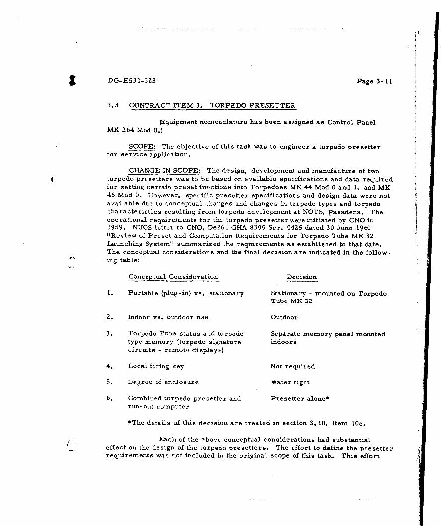
3.3 CONTRACT ITEM 3. TORPEDO PRESETTER
(quipment nomenclature has been assigned as Control PanelMK Z64 Mod 0.)
SCOPE: The objective of this task was to engineer a torpedo presetterfor service application.
CHANGE IN SCOPE: The design, development and manufacture of twotorpedo presetters was to be based on available specifications and data requiredfor setting certain preset functions into Torpedoes MK 44 Mod 0 and 1, and MK46 Mod 0. However, specific presetter specifications and design data were notavailable due to conceptual changes and changes in torpedo types and torpedocharacteristics resulting from torpedo development at NOTS, Pasadena. Theoperational requirements for the torpedo presetter were initiated by CNO in1959. NUOS letter to CNO, DeZ64 GHA 8395 Ser. 0425 dated 30 June 1960"Review of Preset and Computation Requirements for Torpedo Tube MK 3ZLaunching System" summarized the requirements as established to that date.The conceptual considerations and the final decision are indicated in the follow-ing table:
Conceptual Consideration Decision
1. Portable (plug-in) vs. stationary Stationary - mounted on TorpedoTube MK 32
2. Indoor vs. outdoor use Outdoor
3. Torpedo Tube status and torpedo Separate memory panel mountedtype memory (torpedo signature indoorscircuits - remote displays)
4. Local firing key Not required
5. Degree of enclosure Water tight
6. Combined torpedo presetter and Presetter alone*run-out computer
*The details of this decision are treated in section 3. 10, Item l0e.
Each of the above conceptual considerations had substantialeffect on the design of the torpedo presetters. The effort to define the presetterrequirements was not included in the original scope of this task. This effort

DG-E531-323 Page 3- 12
was provided for by contract Modification6,i dated 3 April 1961.
PERFORMANCE:
1) Design Approval Package
A preliminary design approval package, providing for pre-setting Initial Search Depth (ISD), Search Floor and Gyro Angle, for TorpedoesMK 44 Mod 0 and 1, and MK 46 Mod 0 was submitted to NUOS on 15 July 1960,via Arrna letter ERB-E53 I- C4239.
As a result of a meeting at NOTS, Pasadena, on 10 August -1960, the preliminary design approval package was modified to include theadditional presetting requirements for Torpedoes MK 44 Mods 2, 3 and 4. Therevised preliminary design approval package was resubmitted to NUOS on16 September 1960 by Arma letter ERB-E531-86. Approval of the design con-figuration and authorization to proceed was given in NUOS letter De 1-T:LFR:akm-8200 of I November 1960, based on agreemenms reached at a technicalconference at NUOS on 22 September 1960. Additional changes resulted froma technical conference of 9 November 1960 and the final design approval package
-•. was submitted to NUOS by Arma letteT ERB-E561- 124 of 30 November 1960. andapproved by NUOS letter Del-TI:TAL:akm-8510/TERNE of 16 January 1961.
2) Torpedo Presetter Description
The presetter (Control Panel MK 264 Mod 0) was designedfor mounting either indoors (bulkhead mounting in UB Plot) or outdoors (on theTorpedo Tube MK 32). The illumination provided, therefore, had to meet both
dark adaptation and outdoor intensity requirements.
The front cover display consists of an auxiliary plate and allfunctional switches and indicators. The unit contains a mechanical interlockwhich precludes setting ISD below Search Floor. The unit is gasketed andsealed to make a water tight package. The sandwich type construction of thecover incorporates a thermo- sheet heating element for de-icing of externalcontrols and indicators.
The presetter is capable of presetting initial search depth,and search floor or gyro angle for torpedoes MK 44 Mods 0, 1, 2, 3, 4 andMK 46 Mod 0. Presetting is accomplished by a voltage bridge circuit, halfof which is in the torpedo and half in the presetter. Bridge unbalance causesLedex units in the torpedo to step in the direction to produce balance; unbalanceis detected by an ultrasensitive current relay, a Barber Coleman Microposi-tione r.
I

DG-E531-323 Page 3- 13
The response of the torpedo is visually indicated by set lampson the presetter. This is insured by circuits causing the torpedo Ledexes tostep at least once on pressing the insert button, even though the torpedo hasbeen previously set to the proper setting, and then seeking the designated posi-tion. These lamps will go out when the torpedo is, fired or when any switch isdisturbed.
A time delay circuit is included in the presetter in line with thefire signal which is initiated at the torpedo tube. The purpose of the time delayis to fire the gyro squib prior to energizing the solenoid valve at the tube, sothat the gyro will have attained full speed and will be in control by the time thetorpedo enters the water.
Circuit breakers are provided for both presetting power andfiring power so that a momentary short will trip the breakers, which can beeasily reset, and will not blow fuses in the UBFC switchboard.
Used in conjunction with the presetter is the mechanical memoryunit, designated Control Panel MK 264 Mod 0 Memory Unit. It indicatescurrent torpedo complement status and provides a ready reference chart for the"various preset switch positions for each of the different torpedoes.
3) Related Documentation
The Parts Provisioning List was submitted by Arma letterJFMcC-A453-CZ438 of 24 April 1961 and approval was indicated by teleconNUOS (Buben) to Arma (Romano) on Z6 June 1961. Revisions reflectingchanges during development were forwarded by Arma letter JFMcC-A453-C6409 of25 October 1961. All other documentation including the instruction book wasprepared and furnished under Item 5, New Design Documentation. The instructionbook is identified as OP30Z9, Control Panel MK 264 Mod 0.
END ITEM DELIVERY: The two units, Control Panel MK 264 Mod 0including Memory Unit, and two sets of repair parts, were shipped to NUOS on21 June 1961 as DDZ50-Partial Shipment No. 2 under the subject contract.

DG-E53 1-323 Page 3-14
3.4 CONTRACT ITEM 4. ORDALT KITS FOR ATTACK DIRECTOR MK 5 MOD 3
SCOPE: Define Requirements and Engineer for Service Application
The object of this task was to determine the feasibility ofincorporating three modifications into the Attack Director MK 5 Mod 3 and togenerate an ordalt for those that were feasible. The three modifications con-sidered were:
• •. Automatic reception of target depth information.
Utilization of range rate information in problem solution.
Computation of aim point fo- the over-the-side torpedoes withrunout (Torpedoes MK 44 and MK/46).
CHANGE IN SCOPE: As a :result of Arma's investigation, recommenda-tions were made in March 1961 to delete the addition of automatic depth inputinto the Attack Director. The Arma Study Report which summarized theinvestigation was forwarded to NUOS by Arma letter JFMcC-A453-C1693dated Z3 March 1961.
NUOS letter Del-T:TAL;akrn 8200 of 22 September 1960 indicatedthat the Attack Director MK 5 Mod 5 would replace the Attack Director MK 5Mod 3 on the Terne ships. The Attack Director MK 5 Mod 5 utilizes range rateinformation in its problem solution. Therefore, the effort to define require-ments and engineer for service application the utilization of range rate informa-tion in the Attack Director MK 5 Mod 3 was no longer required.
NUOS letter DeZb4:CHA:kay 8395 Ser. 0425 of 30 June 1960,indicated that modification of the Attack Director MK 5 Mod 3, to handle theover-the-side torpedo computation problem, is not readily possible.
Arma study report for Fire Control Requirements for LaunchingOver-the-Side Torpedoes (DR-E652-21) forwarded to NUOS via Arma letterJFMcC-A453-C6162 of 21 October 1960, concluded that doctrine firing of over-the-side torpedoes is feasible, that a computer is not justifiabl4 but that a mech-anical aid to minimize decision making is recommended. This letter recommend-ed a contractual change.
Contract Modification 8, dated 3 April 1961 made the followingspecific changes to the original effort:
Changed the Attack Director MK :5 Mod 3 to- be modified by theOrdAlt:s to Attack Director MK 5 Mod 5.

DG-E531-323 Page 3-15
... Deleted the effort to define requirements for utilization of rangerate information and engineer it for service applicability.
... Directed Arma to hold in abeyance the effort to define require-ments for addition of automatic target depth and over the side torpedocomputation pending completion of the feasibility studies.
Contract Modification 10, dated 17 August 1961, made thefollowing specific changes to the original effort (NPO Brooklyn letters C- ll:jwN140(lZZ)69961B dated 2 February 1961 and Cl-2:ld N140(1Z2)69961B dated7 July 1961):
... Deleted the effort to define requirements for the incorporationof automatic depth input and over-the-side torpedo computation (less theeffort expended in the preparation of Arma report of Automatic DepthInput Study). Similarly the conclusions reached in Arma study Reportfor Fire Control Requirements for Launching Over-the-Side Torpedoes(DR-E652-21) led to the deletion of the effort to define the changes to theAttack Director MK 5 Mod 3 for the addition of aim point computationfor over-the-side torpedoes. Armals effort in preparing the report wascompleted prior to Amendment 10.
0.. Deleted the Engineer for Service Application effort for theincorporation of automatic depth input and over-the-side torpedo compu-tation.
... Provided for the additional effort of preparing a Short FormOrdAlt to the Attack Director MK 5 Mod 3 to provide Computed Sonar Range(high speed only) as an output signal. The need for this functional require-ment was established by Arma in performing the Terne system integrationeffort. At NUOS-Arma conference of 2/10/61, this requirement waspresented and discussed and resulted in this contractual change.
PERFORMANCE (Effort Accomplished):
1) Preparation of Arrna study report of Automatic Depth InputStudy which was forwarded to NUOS via letter JFMcC-A453-C1693 dated 23March 1961 (DDZ50-Partial Shipment No. 5 of 26 October 1961).
2) Preparation of Arma study report for Fire Control Require-ments for Launching Over-the-Side Torpedoes which was forwarded to NUOSvia letter JFMcC-A453-C616Z dated 21 October 1960. (DDZ50-Partial ShipmentNo. 5 of 26 October 1961.)

DG-E531-3Z3 Page 3-16
3) Preparation of Short Form OrdAlt to Attack Director MK 5Mod 3 for computed sonar range (official NAVWEPS number never assigned).
It should be noted that an OrdAlt to the Attack Director MK 5Mod 3 was also prepared under Contract Item i0e in connection with the LaunchRange Display Unit installation.
(I

DG-E531-323 Page 3-17
3.5 CONTRACT ITEM 5. NEW DESIGN DOCUMENTATION
SCOPE: The purpose of this task was to furnish the following documentationfor the signal converter (Contract Item 1), and the torpedo presetter (ContractItem Z):
Documentation to be Supplied Applicable Military Specifications
Record Plans and Lists of Drawings MIL-D-70327
Electron Tube and Semi Conductor Form DD 816Complement Report
Bill of Materials MIL-STD-295, NAVINST 3900.3
Military Specification OSTD 67
Tentative Clarification of Defects OSTD 78; OP 2161
Factory Acceptance Tests NAVORD OD- 10500
Provisioning Parts List MIL-P-Z1078
Instruction Book in Preliminary Form OP- 1 (as a guide)
Non-Standard Parts List MIL-F- 18870A
Recommended Repair Parts MIL-F- 18870A
PERFORMANCE (Change in Scope): Tables 5-1 and 5-2 list all docu-mentation prepared and furnished for the signal converter (Contract Item 1) andthe torpedo presetter (Contract Item 3), respectively. The following informationis supplementary to the tables and details changes in performance requirements.
1) Record Plans and List of Drawings.
A clarification of MIL-D-70327 was requested in October 1960with respect to vendor drawings and existing drawings. This clarification wasstated in Arma Document 521-000-898 and was approved by NUOS in their letterDel-T:TAL:dsr 8510/Terne of 21 October 1960. The requirement for authenti-cated drawings of both the signal converter and the torpedo presetter weredeleted by contract modifications as follows:
a. Signal Converter. Record plans and drawing lists submitted18 October 1961 by Arma letter JFMcC-A453-C6Z16 were held in abeyance byNUOS pending review. Subsequently it became apparent that further procurement

SDG-E531-3Z3 Page 3- 18
of the signal converter was not expected. Therefore authenticated originals andphoto tracings were no longer required and the unauthenticated paper originalswere considered acceptable (NUOS letter Del-T: LFR:akm-8510/Terne of 1 March1962) as an end product. Arma letter JFMcC-A453-CZZ3Z of 26 March 1962requested that the requirement for authenticated drawings be deleted from thecontract and also submitted information on the decrease in contract priceresulting from the deletion. Modification 18, dated 17 May 1962, provided fordeletion of the requirement.
b. Torpedo Presetter. The final design drawings were submittedto NUOS for approval by Arma letter JFMcC-A453-4913 of Z2 August 1961.Subsequently, NUOS letter Del-T:LFR:akm-8510/Terne of 1 November 1961indicated that unauthenticated paper originals were acceptable as deliverable endproducts. Arma letter JFMcC-A453-C7296 of 4 December 1961 requested thatthe requirement for authenticated drawings be deleted from the contract andfurnished the information on the resulting decrease in contract price. Modifica-tion 16 provided for deletion of the requirement.
2) Instruction Books - Decrease in Quantity.
"NUOS directed in their letter D'el- T: LFR:akm- 8510/TERNE- Ser.0927 of 7 December 1961 that six copies of the signal converter OP 3028 in-struction books be furnished for final review and approval in advance ofscheduled deliveries of the end items. In discussions summarized in Armaletter JFMcC-A453-CZZ37 of 4 April 1962 to NUOS, it was indicated that thequantity of signal converter books to be delivered would therefore be reducedfrom 300 to 260, and requested contract modification. Modification 20 providedfor this change without change in cost.
The torpedo presetter instruction book, OP 3029 Control PanelMK 264 Mod 0 was reduced in quantity from 300 to 20 by NUOS letter Del-T:LFR:akm-8510/TERNE - Ser. 0927 of 7 December 1961. This quantity was consideredadequate to meet program requirements. Arma letter JFMcC-A453-C-2064 of 20March 1962 advised NPO Brooklyn of the reduction in contract price resultingfrom the decreased effort and requested a contract change. This was alsocovered by contract Modification 20.

DG-E53 1-323 Page 3- 19
-4
0. aA~'
0 '0 N0aa' 4 -41a
-4 C4) -1 4> 10 N
N >0 a''.
o bo ;q
140
10 k4J 0 0
0
0-41
,-4 00 o
4-1*~~ 00 N
Un W
tA
0. '0 ~ U
H A U) '
z E0 44 U
0 u- 4)
z4 0) u- 10. ,4
0 H~ 4) 0) Q
Cit U 0 0 1-4 k4 k
P4 ~ P r4 '- ,d
0- -4 >14E- m 0 0m 1+4 u 0 "A
4)o 0 LO d ,~ .
0 it 4) %H 04 0 m. ~4J Cl
H ~ ~ ( P4 0 00) ~ Q 4 1
0. U H 1 U cd4ý Cd P
44 M > E44
~ 4) 0u 4J 4-4 4)Hý4 0
-% o 14 14 0d(~4 4) 0 4 U0 4) *H > ~ ~ .
-9 N

- ~ Page 3-20DG-E53 1-323'0-
., '0 '0or-4 4 4j 41
u~0 0
r-4
0'
14 N4'0 '
0 aa, '4
a'4 0 0
0'
- a'
0. -4
U- -4'0a
o~~ o.U .
~0 '0uCi n N w , L
Cd u 0 0 .,
AZ E-. 4 U&Uý N 4) 04 cI i'' id -4
o4- 0 -'- N4)- jZ 0- 0
4) . 0 k ;
.. 44 '440 ~ Q)
4 P' P
'o o LO 0. od-4
0 o~ 0C
4~0. 44t )
U 0>
u > 0

DG-E53 1-3Z3 Page 3-21
104
0-
> a,
-44
44 4
0
p 4 ~uU
to 04
N N
'0
-41-
'o u u
0 N
-:14
4)

DG-E531-323 -.Page 3-ZZ
-4 '
-Z -41-4 N4 a
> q u0 1400 N
0'
4N enN'.
NN N
a,-44N0 .0N
a',00 0'4
o to
z 4
4. 'e'>0
-4 4f -4
0
0 '
-4 -4
1U 0 '.d a,10
0 a''0 0'0 P
Hu ;4 41
H4 00 co~. 4 '
44N 00 N (fn N '0
00
0- LAt04 Ln ;
0A 0
0 04
o ok 64.
4) 0 u 4J
'.4 4) (dz Ili -4 4) N A) ,
0 0 cd 0.
14: .. P4 ( -4 4) '404 -4
H- 44 4) (d 'p 0Apq ~ 0 ) C 0
k~ 0 -d . ,I4 -4 '.gC.) 04 m4 9 4) 4.
0 u ) C.) &S 04)
04 P4 40 .0 0 (d 4)
Ud E4 04 0U 0 *u k4 ()
0) (d 41 m CO
41 '0 .q k u (d ,C
m ~ r- k d104
r, 0- .0 Ud M O -.
d~
) ~ ~ ~ I -) -'I -4Cd. ~ .
0 * *
04 N4 4) LA

DG-E531-323 No Page 3-23
-4 0D
41 -4 4
"04 41.
04
-4
a,
0 1
4 k
N
1.-4
'. -4 -N' '0' 14 a, -40
-4 1' %0 a, '
14 a% 4
0 P4 P4 4
*~~c 00 >:' 44 ~ )
N
.'.0 1-4
N ~ Z 00 k~~0O u-
0-H -
41 )
4) w~ 0 41 0 0H 04 5 ,- H 0
40 (t oo N0 4 .k10
P4 &; .1104 a) 04 0
u 04 ,- 4 4) 0'40 4.1. 5 04u. U) u ~ Id1
1q4)u 00k N 0 0 1
U) w 0 1. *- k) -44J Ln r 14 r-4 (d~4) 4~ -4 >- r4) 4) 0, **4 0 4.
'-4 n4 14 H -4 U)q
0 0*
0.

D0E531-323Page 3-Z4
00 00
- t -
0.
z z
0 0 '.D0' 00a' 0
-e -
o ~ -i FxF-i
od 0 0 0
'Q) -ý -
oo -to- ) 04
N u
0 o 4
0 j0 0
00
0 u 0 u 0
u p-i

DG-E531-323 Page 3-25
3.6 CONTRACT ITEM 6. MODIFIED EQUIPMENT DOCUMENTATIONFOR ATTACK DIRECTOR, ITEM 4
SCOPE: The documentation to be furnished under this task was:
OrdAlt Record Plans and Lists of Drawings
Addenda Chapters to the OP for Attack Director MK 5 Mod 3
OrdAlt Document
As previously discussed under Section 3.4 (Contract Item 4),the OrdAlt tasks to the Attack Director MK 5 Mod 3 as originally defined weredeleted by contract Modifications 8 and 10 and consequently, related documenta-tion was no longer required. Contract Modifications 8 and 10 deleted Item 6in its entirety.

A
DG-E531-323 Page 3-26
3.7 CONTRACT ITEM 7. NORWEGIAN EQUIPMENT DOCUMENTATION
SCOPE: The purpose of this task was to prepare and furnish 300 copiesof preliminary instruction books for the Norwegian equipments. that were to befurnished under a contract between Kongsberg Vaapenfabrikk, Norway (KV) andNUOS.
Accomplishment of this task was predicated on GFM consistingof Norwegian furnished drawings, lists, specifications, test data and procedures,and repair and maintenance procedures for the TERNE equipments.
The instruction books furnished were as follows:
NAVSHIPS 94181 Sonar Depth Determining Group
AN/SQA- 16 (XN- 1), Vol.I and Vol. II- Drawings
NAVWEPS OP 3030 Analog Computer MK 142 Mod 0
NAVWEPS OP 3031 Position Indicator MK 99 Mod 0 and"Indicator Panel MK 263 Mod 0
NAVWEPS OP 3032 Firing Panel MK 262 Mod 0
NAVWEPS OP 3033 Rocket Thrown Depth Charge MK 3 Mod 0
NAVWEPS OP 3034 Terne Launcher and Loading HouseEquipments, Vol. I and Vol. II- Drawings
NAVWEPS OP 3036 Dud Jettisoning Rocket MK I Mod 0
NAVWEPS OP 3037 Power Distribution Panel MK 261 Mod 0
The sonar books (NAVSHIPS 94181) were prepared using MILspecification 15017C as a guide. The draft manuscripts were furnished BUSHIPSfor review, approval and assignment of a NAVSHIPS number and title by Armaletter JFMcC-A453-C4114 of 7 July 1961. Approval, designation and a distributionlist contained in BUSHIPS letter N140(1Z2)69961B-Item 7; Serial 242-912 of 24August 1961, were transmitted to Arma by NPO Brooklyn letter C1-Z:tj of 1 Septem-ber 1961.
All the other instruction books were prepared based on usingOP-1 as a guide. NUOS Standard 10 was subsequently used as applicable for
DG-E531-323 Page 3-27
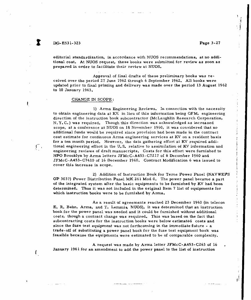
editorial standardization, in accordance with NUOS recommendations, at no addi-tional cost. At NUOS request, these books were submitted for review as soon asprepared in order to facilitate their review at NUOS.
Approval of final drafts of these preliminary books was re-ceived over the period 27 June 1962 through 6 September 1962. All books wereupdated prior to final printing and delivery was made over the period 13 August 1962to 10 January 1963.
CHANGE IN SCOPE:
1) Arma Engineering Reviews. In connection with the necessityto obtain engineering data at KV, in lieu of this information being GFM, engineeringdirection of the instruction book subcontractor (McLaughlin Research Corporation,N. Y. C.) was required. Though this direction was acknowledged as increasedscope, at a conference at NUOS on 18 November 1960, it was considered that noadditional funds would be required since provision had been made in the contractcost estimate for continuous Arma engineering services at KV on a resident basisfor a ten month period. However, the data gathering effort at KV required addi-tional engineering effort in the U.S. relative to assimilation of KV information andengineering reviews of draft manuscripts. Costs for this effort were furnished toNPO Brooklyn by Arma letters JFMcC-A453-C7ZI7 of 8 December 1960 andJFMcC-A453-C7410 of 16 December 1960. Contract Modification 6 was issued tocover this increase in scope.
A
Z) Addition of Instruction Book for Terne Power Panel (NAVWEPSOP 3037) Power Distribution Panel MK 261 Mod 0. The power panel became a partof the integrated system after the basic equipments to be furnished by KV had beendetermined. Thus it was not included in the original Item 7 list of equipments forwhich instruction books were to be furnished by Arma.
As a result of agreements reached 23 December 1960 (in teleconE. R. Behn, Arma, and T. Lernmis NUOS), it was determined that an instructionbook for the power panel was needed and it could be furnished without additionalcosts, though a contract change was required. This was based on the fact thatsubcontracting costs for the instruction books were below estimated costs andsince the fuze test equipment was not forthcoming in the immediate future - atrade-off of substituting a power panel book for the fuze test equipment book wasfeasible because the equipments were estimated to be of comparable complexity.
A request was made by Arma letter JFMcC-A453-CZ63 of 16January 1961 for an amendment to add the power panel to the list of instruction

i
DG-E531-323 Page 3-Z8
books to be furnished. NUOS letter Del-T:LFR:akm-8510/TERNE of 14February 1961 to NPO Brooklyn requested contract modification. Modification4 was then issued to cover this change.
3) Incorporation of KV Drawing Changes. The original drawingsof TERNE equipments furnished by KV were based on the T4RNE system for theNorwegian destroyer Bergen and the development of the first of the two systemsto be supplied the U. S. During production of the first and second systems,continual drawing changes were received. Arma letter JFMcC-A453-C4994 ofZ4 August 1961 stated the cost of additional efforts required for proper integra-tion of these changes, and requested a contract modification to add the requiredfunds. Contract Modification 9, dated 19 July 1961 was issued to cover thecost of incorporating all KV drawing changes. The Norwegian equipment draftmanuscripts were updated accordingly and included all changes and final drawinginformation supplied by KV.
4) Decrease in Quantity of End Items. In the NUOS letterDel-T:LFR:akm 8510/TERNE; Ser. 0927 of 7 December 1961, Arma wasdirected to furnish six copies of each of the Norwegian equipment instructionbooks for final review and approval in advance of scheduled deliveries of theprinted end items. Arma letter JFMcC-A453-C2237 of 4 April 1962 to NUOSindicated that the six advance copies could be provided and that the quantity ofinstruction books to be delivered would therefore be reduced from 300 to 250to keep costs the same. Modification Z0 provided for this change at no changein cost.
5) Deletion of Instruction Book for TERNE Fuze Test Equip-ment (Item 7. i). The preparation of this item was held in abeyance pendingthe receipt of GFM data for this instrument. Arma letter JA-A453-C8303of 25 October 1962 stated that this item was open and awaiting the necessaryinformation from NUOS or KV. Contract Modification 20 indicated that the"status for this document was still pending." Contract Modification 21 delineatedthe "delivery to be as mutually agreed upon when work on Item 7. i is started. "NUOS letter Te3:FWK:dsr;8510/TERNE of 8 April 1963 deleted the requirementthat the TERNE Fuze Test equipment instruction book (OP 3035) be supplied underthe subject contract.
PERFORMANCE:
1) Data Gathering Effort at KV. At a meeting at KV in December1959, it was indicated by KV that TERNE instruction books were to be furnished byKV for the Norwegian Navy. The information in these books were to be the basisfor the U.S. instruction book effort, since the Norwegians had no experience with

DG-E531-323 Page 3-29
U. S. publication specifications and approval procedures. At a second visit toKV (March 1960) it became apparent that Norwegian instruction books could notbe made available in time. In July, 1960, at a third meeting at KV, tentativearrangements were made to gather the necessary technical data for preparationof the instruction books for the Terne U. S. equipments.
This was accomplished during the period 14 November to 18December 1960. The effort involved frequent conferences with individual KVengineering personnel to determine equipment functional operation, and mechanicaland electrical data. Drawings were obtained and reviewed and needed informationand detailed data was requested. Documentary information such as test proce-dures, test data, and circuit alignment information was not available. Suchinformation as well as troubleshooting data and repair and maintenance require-ments and procedures were not obtained.
2) KV Engineering Review. Draft manuscripts preparedfollowing the data gathering effort were furnished KV for engineering review andcomment in March 1961. In April 1961, a conference -was held at KV to reviewKV engineering comments and to obtain additional information. At this conference,the drafts were approved by'KV as satisfactory and representative of the equip-ment. Both new and additional drawings were obtained at this time; however, thenecessary repair and maintenance data was not available.
The drafts were further reviewed by KV personnel during systeminstallation on the DE 1035 at Long Beach Naval Shipyard in August and December1961. This review served to authenticate information added since the earlierdata gathering and review at KV.
3) NUOS Review of Drafts. The preliminary draft manuscriptswere furnished NUOS for approval for use during the TERNE Classroom TrainingProgram of August 1961, at Long Beach Naval Shipyard. The submittal letter of26 June 1961 (Arma letter JFMcC-A453-C3877) emphasized that the technicalcontent of the instruction books was based on information received from KY, anddid not include changes or test information resulting from checkout of the systemon the Bergen. The general comment made by NUOS was in connection with thelack of repair and maintenance information in the book.
4) GFM supplied by KV. The information furnished by KV in-cluded the necessary electrical and mechanical assembly drawings to describethe equipment physically and functionally. However, the electrical drawings didnot contain detailed information normally found on U. S. drawings. Though thespecifications furnished were not complete for all equipments, they were usedto determine parameters and system performance data. There were no "test"specifications, detailed in-line test procedures or data comparable to FATS
I DG-E531-323 Page 3-30
for reference furnished. As a result, the maintenance information containedin the end item preliminary instruction books could not be completed.
NUOS letter Del- T;LFR;akm- 8510/ TERNE-Serial 09Z7 of7 December 1961 stated that KV intended to Provide GFM test and maintenancedata, and that no action would be taken at that time on Arma letter JFMcC-A453-C5144 of 30 August 1961 outlining a proposal for generating this data.Complete GFM in this area was not furnished. Arma letter JFMcC-A453-C3550of 1 May 196Z, again called attention to the lack of needed government furnishedtest and maintenance data. Arma letter JFMcC-A453-C5373 of 2 July 1962summarized the entire repair and maintenance data problem and recommendeda planning conference at KV to determine means for generating the needed dataas well as to resolve various system problem areas.
5) Additional Copies Made Available. Throughout the productionof the Norwegian equipment instruction books, copies of interim drafts werefurnished at NUOS request to:
Kongsberg Vaapenfabrikk, Norway 2 copies of each OP
"Long Beach Naval Shipyard, California 1 copy of each OP
BUSHIPS Z copies sonar NAVSHIPS 94181
BUWEPS 1 copy of each OP
OPTEVFOR Z copies of each OP
DE 1035 1 copy of each OP
DE 1036 1 copy of each OP
Classroom and Shipboard Training 15 copies of each OP andNAVSHIPS 94181
NWL, Dahlgren 2 copies OP 3033 Rocket ThrownDepth Charge MK 3 Mod 0
6) Final NUOS Review. Six ozalid copies each of the instruc-tion books were furnished NUOS for approval prior to printing final copies, duringthe period 21 March 1962 - 7 June 196Z. Comments and additional informationrequested were incorporated during the Arma final review task from June 1962
_ through November 1962.

DG-E531-323 Page 3-31
7) Incorporation of Changes Due to Installation, Checkout,BUWEPS and OPTEVFOR Evaluations. The following information and changeswere incorporated at no additional cost in the instruction books before they werefinalized and printed for end item delivery.
.. •. Added information resulting from ballistic changes to computer.
Changes to revise computer problems in OP 3030 to providemore realistic values.
... Addition of a salvo problem, to the two single fire problems.
Revised texts to incorporate change in salvo spread from13.2 yds. to 20 yds.
... Added weatherhood description and operation.
... Revised description of Dud Jettisoning Unit.
(*.. Revised launcher hoist hydraulic system descriptions.
Revised transducer hoist description and illustrations.
S... Updated sonar and computer air conditioning equipmentdescriptions and operation.
S .. Added launcher and loading house equipment and maintenancerequirements.
... Added to line pattern potentiormeter information.
... •Revised description of Rocket Thrown Depth Charge MK 3 toincorporate fixes required by NWL tests of fuze.
... Revised fuze magazine information to incorporate type ofmagazine actually furnished by KV.
Added fuze test and battery charger information to reflectuse of shipboard fuze test set.
Incorporated equipment wiring changes to reflect changesresulting from installation and checkout.

SDG-E531-323 Page 3-32
END ITEM DELIVERY. All Norwegian equipment OPs were delivered onDD 250 forms in accordance with contractual requirements, as listed below:
Item Partial Ship- DeliveryNo. Description Quantity -nent No. Date
7a & NAVSHIPS 94181 Preliminary- 250 each 19 10 Jan, 19637b Sonar Depth Determining Group
AN/SQA- 16 (XN- 1), Volumes
I and II
7c NAVWEPS OP 3030 Prelim- 250 17 23 Nov. 1962inary - Analog Computer MK 142Mod 0
7d NAVWEPS OP 3031 Preliminary - 250 16 13 Sept. 1962Position Indicator MK 99 Mod 0and Indicator Panel MK 263 Mod 0
7e NAVWEPS OP 3032 Preliminary - 250 16 13 Sept. 196ZFiring Panel MK 262 Mod 0
7f & NAVWEPS OP 3034 Preliminary - 250 each 19 10 Jan. 19637g Terne LauncwheI and Loading House
Equipment, Volumes I and II
7h NAVWEPS OP 3033 Preliminary - 246 18 15 Nov. 1962Rocket-Thrown Depth ChargeMK 3 Mod 0
7j NAVWEPS OP 3036 Preliminary - 250 15 13 Aug. 1962Dud-Jettisoning Rocket MK 1 ModO
7k NAVWEPS OP 3037 Preliminary - Z50 16 13 Sept. 1962Power Distribution PanelMK 261 Mod 0
i

SDG-E531-323 Page 3-33
The repro material for the Norwegian equipmexA OPs wasforwarded on DD 250 forms in accordance with contractual requirements,as listed below:
Partial Shipment No. Delivery Date Repro Material Forwarded
20 Z8 February 1963 NAVSHIPS 94181NAVWEPS OP 3034
21 13 March 1963 NAVWEPS OP 3030NAVWEPS OP 3031NAVWEPS OP 3032NAVWEPS OP3033NAVWEPS OP 3036NAVWEPS OP 3037

SDG-E531-323 Page 3-34
3.8 ITEM 8. SYSTEM DOCUMENTATION
SCOPE: Under this task, as originally stated in the contract, Arma wasto prepare a Weapon System instruction book (including description and opera-tion, system checks, and system functional schematic diagrams) in threevolumes. The deliverable end products were to be:
(a) One (1) set of repro, consisting of one (1) set printer'snegatives and artwork.
(b) Three hundred (300) printed copies of the Weapon Systeminstruction books.
The instruction book was to be prepared using OP- 1 as a guide.The system checks in conjunction with the system functional schematic diagramswere to fulfill the following needs:
Provide a basis for the initial complete system installationcheckout.
... Provide a basis for determining overall system readinessduring at sea operation prior to system use.
... Provide a basis of acceptability for equipment operation follow-ing repair during overhaul periods.
The scheduled delivery of the system instruction books wasto be in accordance with schedule set forth in Arma Technical Proposal A60-7of Z9 February 1960. The dates given in A60-7 were:
Draft copy - 1 May 1961
... Manuscript copy for approval - 10 October 1961
300 printed copies - 4 months after NUOS approval

DG-E531-323 Page 3-35
INCREASE IN SCOPE
The original plans for the ASW Weapon System on the DE1035 and DE 1036 called for the TERNE Weapon equipments to be integratedinto the existing FCS MK 105 which when modernized would have the follow-ing weapon complement:
... Rocket Thrown Depth Charge MK 3 Mod 0
... Over-the-Side Torpedoes MK 43, MK 44, and MK 46
Depth Charges MK 9 and MK 14
Shortly after the inception of the program in August 1960,OPNAV Instruction 0420. Z7B disseminated information to the effect thatTorpedo MK 37 Mod 1 was to be installed aboard the TERNE vessels. Areview was then made to determine the effects of installing Torpedo MK 37Mod 1 on the DE 1033 class vessels. The results of this review were publishedas Arma Document A60-47, dated Z0 September 1960. This report, togetherwith budgetary prices for the increased contract effort that would be caused byadding the Torpedo MK 37 Mod 1 to the TERNE vessels, was hand deliveredto NUOS in September 1960. The ceport contained a recommendation that thesubject contract be modified to permit Arma to integrate the Torpedo MK 37Mod 1 weapon requirements, as defined in OPNAV Instruction 0420. 27B, intothe weapon complement for the TERNE (DE 1035 and DE 1036) vessels.
NPO Brooklyn letter C-II:jwNI40(12Z)69961B of 22 November1960, directed Arma to proceed with the addition of the Torpedo MK 37 Mod 1into the existing weapon complement on the TERNE vessels. Concurrently,as outlined in OPNAV Instruction 0420.27B, the Depth Charge Rack MK 9 wasto be removed.

DG-E531-323 Page 3-36
Subsequently, Contract Modification No. 7 of 3 April 1961increased the funding under the contract to provide for the required documenta-tion to be furnished under the terms of the contract to include the installationof Torpedo MK 37 Mod 1 equipment concurrent with the Terne Weapon systeminstallation on the DE 1035 and DE 1036.
Contract Modification No. 12 of 18 August 1961 was issued toclar'ify the requirements of Modification No. 7, regarding Arma DocumentA60-47. Later, in response to Arma letter JFMcC-A453-05416 of 12 September1961, Contract Modification No. 15 was issued on 30 October 1961 withdrawing
.Mpdification No. 12 and amending Modification No. 7 by redefining the require-ments for Arma Document A60-47 and adding that certain GFM relating to theTorpedo MK 37 Mod 1 effort would be furnished.
On 28 February 1961, Arma letter JFMcC-A453-CI1ZZ toNPO, Brooklyn (copy to NUOS) forwarded a revised Terne Program schedulewhich had been up-dated to allow for the additional effort required by the additionof Torpedo MK 37- Mod 1 to the Weapon System complement on the Terne vessels,with the request that the enclosed scheduled, Arma Document CX 13, 35Z, besubstituted for the schedule presently appearing in Arma Document A60-7 of"29 February 1960. This revised schedule changed the delivery dates of theWeapon System instruction book to read
Draft copy - 1 October 1961
Final manuscript for approval - 31 January 1962
... 300 Printed copies - 4 months after NUQSapproval.
Subsequently, Contract Modification No. 11 of 18 August 1961 revised time ofperformance under the contract to the schedule outlined in Arma DocumentCX 13, 352 in lieu of schedule outlined in Arma Document A60-7 of 27 February1960.
Contract Modification No. 14 of 29 September 1961 confirmedthe fact that the existing weapon complement on the DE 1035 and DE 1036 wouldnot include depth charge armament, and it directed that no reference to thisarmament be made in the Weapon System documentation.
PERFORMANCE: The original planning for the Weapon System documenta-tion required the production of a three-volume manual whose coverage was asfollows:

I DG-E53 1- 323 Page 3-37
Volume 1 - System Description and Operation
.Volume 2 - System Check and Maintenance
Volume 3 - System Check and Maintenance Log
The program for the preparation of the Weapon System Manualwas initiated in December 1960. Under the program, some of the effort oforiginating the draft manuscript for Volume 1 was subcontracted to WashingtonEngineering Services Co., Inc., hereinafter referred to as WESCO. The effortof originating the draft manuscripts for Volumes 2 and 3 was to be done by Arma.Following the NUOS review, the effort of correcting the draft manuscripts toreflect the necessary changes would be done by Arma. The effort of typing thefinal manuscripts for all three volumes and the printing of 300 copies of eachof the final manuscripts was subcontracted to WESCO.
When Arma was directed by NPO Brooklyn letter C- hl:jwN140(12Z)69961B to include Torpedo MK 37 Mod 1 in the weapon complementon the Terne vessels, the Weapon System Manual was expanded to four volumes,as follows:
Volume 1 - System Description and Operation
... Volume Z - System General Data and Maintenance
Volume 3 - System Readiness Checks
Volume 4 - System Readiness Checks Log
The program for the preparation of the Weapon System manualwas changed in January 1961 to provide for four volumes in lieu of three volumes.Under the revised program, WESCO was to assist Arma in originating the draftmanuscripts for Volumes 1 and Z; while Arma was to prepare the draft manu-scripts for Volumes 3 and 4. As before, WESCO was to type and print 300 copiesof each of the final NUOS approved manuscripts. Arma was to supply all originalart and the System Functional Schematic diagrams, see Contract Item 10b, fortheir use by WESCO in preparing the final manuscripts.
In April 1961, the System Readiness Checks test data for theTerne Computer MK 142 Mod 0, which had been developed by Arma, was checkedby the IBM data computing facility at NUOS and found to be correct.

SDG-E531-323 Page 3-38
In May 1961, NUOS assigned NAVWEPS OD 15104 as the identi-fication number for the ASW Weapon System MK 1 Mod 0 manual.
In August 1961, thirty (30) copies of Chapter 3 from Volume 1were printed and bound by WESCO for use as a training aid during the schoolat LBNSYD, see Contract Item 10b. Chapter 3 presents a suggested systemoperating procedure as a guide to ship's personnel in developing their standardoperating procedure for ASW Weapon System MK 1 Mod 0.
The draft manuscripts for Volumes 3 and 4 were completed inaccordance with the requirements of the contract. The System ReadinessChecks contained in these volumes served as the basis fr. acceptance of ASWWeapon System MK 1 Mod 0 during its installation and checkout on the DE 1035and DE 1036 at LBNSYD, see Contract Item 10b.
Arma letter JFMcC-A453-C6454 of 27 October 1961 forwardedtwo (Z) each preliminary draft manuscript copies for Volumes 3 and 4 ofNAVWEPS OD 15104 to NUOS for review and comment. On 31 October 1961,four (4) copies of Volumes 3 and 4, respectively, were hand carried to LBNSYD
( where they were subsequently delivered to the DE 1035 and DE 1036, two copiesto each ship.
Arma letter JFMcC-A453-C7985 of 28 December 1961 forwardedtwo (2) each preliminary draft manuscript copies for Volumes 1 and 2 of NAVWEPSOD 15104 to NUOS for review and comment. On 24 January 1962, four (4) copiesof Volumes 1 and 2, respectively, were handcarried to LBNSYD where they weredelivered to the DE 1035 and DE 1036, two copies to each ship,
NUOS letter TeZ:]MPS:dsr-5600/OD of Z3 February 196Z,granted approval to proceed with the preparation of the final manuscripts forVolumes I and Z of NAVWEPS OD 15104. But this letter was subsequentlyfollowed by NUOS letter TeZC:FWK:Ieh-5600/OD of 8 April 1962, which requestedthat the preparation of the final manuscript for NAVWEPS OD 15104 be held inabeyance pending the analysis of results of the Bureau of Weapons Technical andLaboratory Evaluations.
NUOS letter TeZC:FWK:der-8510/TERNE of 6 March 1962, inreply to Arma letter JFMcC-A453-C278 of 2 February 1962 requesting informa-tion relative to the status of the NUOS review of Volumes 3 and 4 of NAVWEPSOD 15104, advised Arma that these volumes were currently being reviewed andchecked during the installation and checkout of the fire control system on theDE 1036. The letter also stated that NUOS expected to complete their review byZ April 1962.

DG-E53 1-323 Page 3-39
Arma letter JLD-A453-C4407 of 31 May 1962 informed NUOSthat all four volumes of NAVWEPS OD 15104 had been technically updated toinclude the results of the BUWEPS Technical Evaluation and also that theSystem Readiness Check test data for the Computer MK 14Z Mod 0 had beenmodified to incorporate the hydroballistic trajectory curves for the TerneRocket which had been forwarded by KV letter U/153/6z/OW/Ga of 16 April1962. The Arma letter also contained a request that the NUOS "hold in abeyance"order of 8 April 1962 be rescinded and that a directive be given to proceed withthe preparation of the final manuscripts for Volumes 1, Z, 3 and 4.
NUOS letter TeZC:FWK:dsr-8510/TERNE of 6 July 1962,granted approval to proceed with the preparation of the final manuscripts forNAVWEPS OD 15104 provided that all information had been updated to includethe BUWEPS OPTEVFOR Operational Evaluation.
At a conference at NUOS on 14 August 1962, Arma pointed outthe need for a cutoff date relative to updating the information contained inNAVWEPS OD 15104. NUOS letter TeZC:FWK:dsr 8510/TERNE of 22 August1962 directed that 27 August 1962 be the termination date for new material to beincluded in the final manuscripts for the Weapon System manual. This letteralso directed that 20-yard spacing for Terne Salvo Firing be incorporated intothe System Readiness Checks.
NUOS speedletter Te2C:FWK:dsr-8510/TERNE of 28 August1962, in response to a telecon from Arma, authorized Arma to publish theSystem Functional Schematic diagrams under separate cover as an addendumto Volume Z of NAVWEPS OD 15104.
Arma letter JA-A453-C8303 of 25 October 196Z to NUOS (copyto NPO, Brooklyn) requested that the schedule for delivery of the WeaponSystem instruction books, NAVWEPS OD 15104, Volumes I, I1, II Supplement,III and IV, be changed to the first week in March 1963 by a modification in thecontract. The letter pointed out that a change in the delivery schedule underthe contract was required because of the many changes to be made in preparingthe final manuscript and also due to the "hold in abeyance" request of 8 April1962.
NUOS letter Te3-T:FWK:pe-4-Z80 of 3 December 1962, re-quested NPO (Brooklyn) to issue a modification to the subject contract to reflecta scheduled delivery date of "prior to 8 March 1963" for NAVWEPS OD 15104,Volumes I, II plus addenda, III and IV. Subsequently, Contract ModificationNo. Z0 of 14 December 1962 revised the deliverable end products for the WeaponSystem manual (Item 8) to read "300 copies of NAVWEPS OD 15104, ASW

(DG-E531-323 Page 3-40
Weapon System MK 1 Mod 0, Volumes I, II plus addendum, III and IV "in lieuof" 300 copies of Weapon System W- 113 Manual (including Description andOperation, System Checks, and System Functional Szhematics - 3 volumes)."The scheduled date of delivery for Item 8 was amended to read "prior to 8 March1963. "
NAVWEPS OD 15104 was delivered in accordance with the termsof the contract in March 1963. The system manual, as published, has thefollowing coverage:
Volume 1, ASW Weapon System MK 1 Mod 0, Description andoperation - contains a general description of system; a functional descrip-tion including the fire control geometry for each weapon; and systemoperating instructions for each shipboard station arranged in tabular formas incident- action- events in chronological sequence.
... Volume 2, ASW Weapon System MK 1 Mod 0, General Data andMaintenance - contains synchro loading diagrams for the system; an equip-mrrit data summaryr which provides a brief de sdriptibn of .the jphysiCal andfunctional characteristics of each equipment in the system including signalinputs and outputs and power requirements; system general maintenanceprocedures and philosophy; and service hints which provide general repairinformation for ready reference.
Volume 2 Supplement, ASW Weapon System MK 1 Mod 0, Gen-eral Data and Maintenance, System Diagrams - contains seventeen systemfunctional schematic diagrams depicting the system wiring for signal andpower flow.
Volume 3, ASW Weapon System MK 1 Mod 0, System ReadinessChecks - contains overall weapon system checks designed to determinewhether the functional operation of each of the fire control equipmentsis in accordance with prescribed requirements. This volume also containsweapon firing circuit and command checks, system alignment checks, andindividual equipment checks for isolating sources of trouble.
... Volume 4, ASW Weapon System MK 1 Mod 0, System ReadinessChecks Log - contains a supply of log sheets in the form of check-off listsor problem record sheets for recording the results of the tests prescribedin Volume 3.

SDG-E531-323 Page 3-41
END ITEM DELIVERY
The volumes of NAVWEPS OD 15104 were delivered on DD 250forms in accordance with the terms of the contract, as listed below:
PartialShipment Delivery
Volume No. Description Quantity No. Date
1 ASW Weapon System MK 1 Mod 0- 300 23 29 Mar. 1963Description and Operation
2 ASW Weapon System MK 1 Mod 0- 300 Z4 29 Mar. 1963General Data and Maintenance
2 ASW Weapon System MK 1 Mod 0- 300 25 Z9 Mar. 1963Supple- General Data and Maintenance,ment Systems Diagrams
3 ASW Weapon System MK 1 Mod 0- 300 22 18 Mar. 1963System Readiness Checks
4 ASW Weapon System MK 1 Mod 0- 300 26 22 Mar. 1963System Readiness Checks Log
The reproducible copy and negatives for NAVWEPS OD 15104(all volumes) were delivered on DD250 as Partial Shipment No. 27, dated 29 May1963.
(i

SDG-E531-323 Page 3-4Z
3.9 CONTRACT ITEM 9. REPAIR PARTS
SCOPE: Furnish two sets of repair parts for signal converter andtorpedo presetter in accordance with MIL-F- 18870A.
PERFORMANCE: Two sets of repair parts for the new design equipments,signal converter and presetter, were furnished for DE 1035 and DE 1036. Theseparts were furnished in accordance with lists approved by NUOS, as outlinedbelow, and they were intended to provide maintenance support over a period ofone year.
... Converter list approved by NUOS letter DeZa- I:REB:jm 8200 of20 March 1961.
Presetter list approved by NUOS letter Del-Th:TAL:akmn 8510/TERNE of 16 January 1961.
END ITEM DELIVERY
1) Signal Converter (Electronic Frequency Converter MK 50Mod 0). Two sets of repair parts were delivered: One set on DD 250 - PartialShipment No. 4 of 14 August 1961 and the other set on DD 250 - Partial ShipmentNo. 3 of 13 July 1961, to Long Beach Naval Shipyard, Long Beach, California.
2) Torpedo Presetter. Two sets of repair parts for the ControlPanel MK Z64 Mod 0 were furnished on DD 250 - Partial Shipment No. 2 of7 June 1961 to Receiving Officer, U. S. Naval Underwater Ordnance Station,Newport, Rhode Island, Attention Del-T.

DG- E531-323 Page 3-43
3. 10 CONTRACT ITEM 10. ENGINEERING SERVICES
Under Item 10 of the contract, Arma was to furnish engineeringservices as required for:
a. Liaisonb. Installation
c. Missile Component Evaluationd. BUWEPS and OPTEVFOR Evaluatione. Related Studies to
(i) Evaluate increased performance of U. S.Ordnance through use of TERNE III Depth Sonar.
(ii) Determine optimum vessel types for TERNE III'systems.
The performance and work accomplished under these tasks isreviewed in the following subsections.
3. 10. 1 CONTRACT ITEM 10a: LIAISON
Scope: This task provided for furnishing engineeringservices in the form of technical liaison with Norwegian and U. S. Navalactivities. The objective of this task was to eliminate program interfaceproblems existing between the Norwegian and U. S. equipments and theshipboard installation. The program geography is shown on the diagram,figure 3- 1.
The need for this task arose because there could not be asystem test of the KV equipment prior to shipboard installation. In viewof schedule requirements and ship availability, the liaison effort was toinclude:
... Surveillance of Norwegian and U. S. equipmentmanufacturing activities.
... Gathering technical data for preparation of systemdrawings (including preparation of functional schematics)and system and equipment instruction books.
... Review of Norwegian prepared documentation.
... Witnessing of Norwegian final equipment acceptance tests.

CONFIDEN
LEGEND
DAHLGREN, VA. - NAVAL WEAPONS LABORATORYGARDEN CITY, N.Y. - ARMA DIVISIONKEYPORT, WASH. - NAVAL TORPEDO STATIONKEY WEST, FLA. - KWESTEVDET
LONDON, ENGLAND - NAVAL PROCUREMENT OFFICELONG BEACH, CALIF. - LONG BEACH NAVAL SHIPYARD:NEW LONDON, CONN. - USNUSLNEWPORT, R. I. - NAVAL UNDERWATER ORD- STA.WASHINGTON, D.C. - BUWEPS, BUSHIPS, BUPERSHORTEN, NORWAY - NORWEGIAN DEFENSE RESEARCH ESTABLISHMENT
KONGSBERG, NORWAY - KONGSBERG VAAPENFABIIKL
OSLO, NORWAY - MILIZARY, AL-LIED ASSISTANCE GROUP -- NDRESAN DIEGO, CALIF. - NAVAL OPERATING BASEPHILADELPHIA, PA- - TELE-DYNAMICS DIVISION - ABAC
KEy poRT,~ WASH.NEWPORT, R.I.
NEW LON
S:'---ARMA. GARDEN
WASHINGTON, D.C
LONG BEACH, CALIF.
SAN DIEGO, CALIF.OPTEVFOR EVALUATIO
" • KEY WEST, FLA.
"BUWEPS EVALUATION
FIGURE 3-1 PROGRAM GE
CONFIDENTIAL
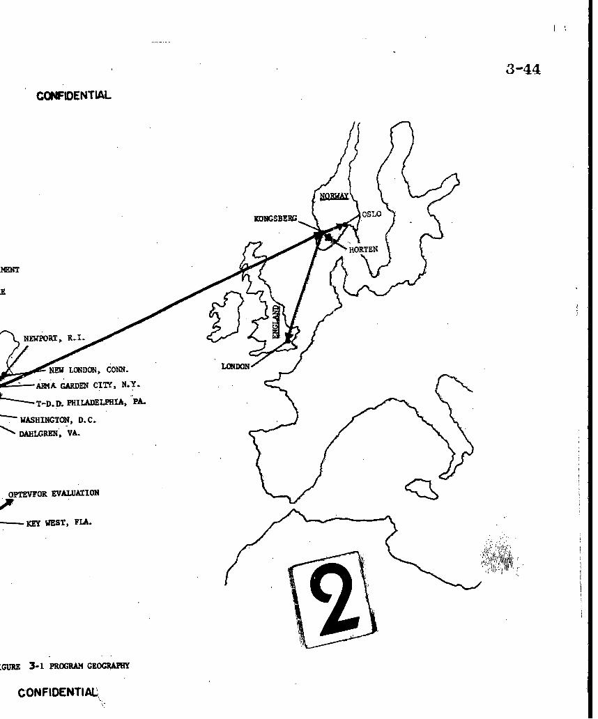
3-44
CONFIDENTIAL
S•" .HORTEI f
14ENT
NEWPORT,, R-I.
NEW LONDON, CONN. LN0
-AR4A GARDEN CITY, NY.-
L ̀ T-D.1D. PHILADELPHIA, "PA.
SWASHINGTON, D.C.
DAHLGREN, VA.
OPTEVFOR EvALUA3ION
ýKEY WEST, FLA.
'GURE 3-1 PROGRAM GEOGRAP
CONFIDENTIAL,

DG-E531-3Z3 Page 3-45
Installation planning with KV, NDRE, BUWEPS, BUSHIPSand LBNSYD.
... Planning for BUWEPS technical evaluation of the system asinstalled on DE 1035.
Performance: The liaison objectives were accomplished throughconferences. These were held to establish program progress, resolve interfaceproblems, and to obtain any available maintenance and installation data. Theconferences are listed in Appendix A.
The activities conferred with most frequently, other than NUOS,were KV and Long Beach Naval Shipyard. The principal meetings at KV arelisted for information purposes but only the first meeting is summarized, sincethe results of this meeting set up the patterns for interchange of information andestablished the basis for technical liaison. To plan for the first U. S. Meetingat KV, a conference was held by BUWEPS in Washington on 10 December 1959.This conference established an agenda for the KV meeting covering systemprinciples, hardware procurement, documentation, services, liaison and con-tractual requirements.
Conference at KV, 14 - 18 December 1959
Purpose: 1. To determine the TERNE equipment to be suppliedby KV and their delivery schedule in order toprovide the basis for a KV-NUOS contract.
2. To prepare a progress plan providing for thenecessary technical liaison for the design, manu-facture and installation of the system on two U. S.destroyers.
Participants: Representatives from
U. S. Naval Underwater Ordnance StationBUWEPSBUSHIPS
Military Allied Assistance Group (MAAG)U. S. Office of Naval Research (ONR) London, EnglandArma Division, American Bosch Arma CorporationRoyal Norwegian Navy (RNN)Norwegian Defense Research Establishment (NDRE)Kongsberg Vaapenfabrikk (KV)

DG-E531-323 Page 3-46
Conclusions: The following agreements were reached:
1. The Terne Computer became part of the basicweapon system.
2. The components to be supplied by KV weredetermined.
3. Quantities of missiles and missile componentsincluding warheads and deliveries for BUWEPSevaluation were established.
4. Arrangements were made for KV to supplyrepair parts lists, drawings and relatedspecifications and instr uction manuals(prepared for the Norwegian Navy.)
5. Packaging and inspection details.
6. Equipment to be procured against NDREspecifications for terne system and major
components.
7. Established requirements and schedules tomeet U. S. installation requirements.
8. Launcher Weapon system blast protection,firing angle limitations, interlock and safetyprecautions were established.
9. Sonar requirements were established.
10. Power Requirements were reviewed.
11. Arrangerments were made for interchange ofinformation for a missile and fuze evaluationprogram.
12. KV to provide engineering services duringdesign, manufacture, installation and "initialtraining".
13. Basic contract requirements for procurementof the Norwegian equipments and services.

DG-E531-323 Page 3-47
Subsequent Meetings at KV. The following meetings wereheld at KV during the term of this contract.
23 Marph, 1960 Arma, NUOS, KV, NDRE
To exchange technical information betweenKV, Arma and U. S. concerning technicalinterface problems relating to the installationof the integrated system in two U. S. ships.
11-28 July, 1.960 Arma, NUOSý BUSHIPS, BUWEPS, KV, NDRE
To review functional diagram of system,determine system cabling and powerdistribution requirements, determine sonar
requirements, logistic support, missile data,and drawing and instruction book documentation.
3 October, 1960 Arma, NUOS, KV, NDRE
To review schedule progress, weatherhooddesign, establish repair parts and reviewproblem areas.
14-18 Nov. 1960 Arma, KV, NDRE
To commence instruction book preparationby Arma at KV; to obtain weatherhood dataand discuss progress.
13-15 Dec. 1960 Arma, NUOS, KV
To review instruction book effort, obtaininstallation data for weatherhood, reviewrepair parts and delivery status of missile
components, single rail launcher and airconditioning equipment.
21 February -
2 March, 1961 Arma, NUOS, KV
To review sonar hoist and transducer installa-tion details, final KV drawings, launcherand weatherhood installation.

DG-E531-32 Page 3448
4 April -
17 April, 1961 Arma, KV
To review instruction book drafts andinstallation data with KV, installation require-ments and engineering services requiredduring training and installation at Long BeachNaval Shipyard.
31 May -9 June 196.1 Arma, NUOS, KV
To review production and acceptance teststatus, delivery schedule, shipping andpackaging, final documentation and installationdetails.
Technical Conferences at Long Beach Naval Shipyard. Informa-tion obtained from KV or generated at Arma was transmitted for installationpurposes. to LBNSYD in a series of conferences. beginning in April 1960.These conferences are discussed in connection with the Installation Task,section 3. 10b.
Norwegian Documentation Review. Under the Liaison task,a review was made of all documentation furnished by KV to. assure compliancewith the documentation requirements of the KV-NUOS contract. This effortwas needed because of differences in drawing practices and types of drawings.The requirements for this documentation are set forth in the NUOS-KV contractand are summarized in Appendix II of Arma Document A60-7, in order todefine the area of effort.
Documentation in the form of drawings and limited specificationswere delivered by KV to Arma at the conferences and by mail. This informationwas reviewed, utilized in preparation of switchboard guidance plans and func-tional schematics and copies sent to NUOS and to the instruction book sub-contractors.
The results of the review are shown in Arma Document DG-E531-187 "Review of Final Documentation, Terne III Equipment", and is Appendix Bof this report.

DG-E531-323 Page 3-4-9
Preparation of Recommended Factory Acceptance Tests.In connection with providing technical assistance to NUOS, a set of recommendedFATS for all equipment being supplied by KV were prepared. These FATSoutlined the minimum acceptance requirements to
Assure satisfactory equipment operation
Assure uniformity of all equipments in each system
Assure satisfactory i1tegration into FCS Mk 105
. Assure satisfactory system operation with minimumshipboard check-out effort.
The information for these FATS was based on the March1961 drawings and information received from KV. The FATS were specificallyprepared as, a guide to the Norwegians in preparing their own acceptancetests. The intent was to minimize shipboard problems.
3.10.2 ITEM 10b: INSTALLATION
Scope: Under this task, engineering support to NUOS wasprovided by Arma in four areas of effort, as follows:
System Integration and Analysis
Preparation of System Functional Schematic Diagrams
System lastallation and Checkout
Training
The original contract provided for the engineering assistancerequired to carry out the above efforts for installing the Terne Weapon equip-ments into a FCS Mk 105 which when modernized would have the followingweapon complement:
., Rocket Thrown Depth Charge Mk 3 Mod 0
... Over-the-Side Torpedoes Mk 43, Mk 44, and Mk 46
Depth Charges Mk 9 and Mk 14
f

1DG-E531-323 Page 3-50
Change in Scope:
Shortly after the inception of the program in August 1960,OPNAV Instruction 0420. 27B disseminated information to: the effect thatTorpedo Mk 37-1 was to be installed aboard the Terne vessels. A reviewwas then made to determine the effects of installing Torpedo Mk 37-1 on theDE 1033 class vessels. The results of this review were published as ArnaDQcument A60-47, dated 20 September 1960. This report outlined theadditional sawchboard and power requirements for DE 1033 and DE 1034(without Terne) and for DE 1035 and DE 1036 (including Terne) resulting fromthe installation of the Torpedo Mk 37-1 Weapon. Three copies of this report,together with budgetary prices for increased contract effort that would becaused by a4ding the Torpedo Mk 37-1 to the Terne vessels, were hand-delivered to NUOS in September 1960. The report contained the followingrecommendations:
... That a FRAM II switchboard be considered forinstallation aboard the DE 1033 and DE 1034.
That the subject contract be modified to provideArma services to integrate the Torpedo Mk 37-1weapon requirements, as defined in OPNAVInstruction 0420. 27B, into the weapon complementfor the Terne (DE 1035 and DE 1036) vessels.
NPO Bklyn letter C-ll:jw N140(1ZZ)69961B of 22 November1960 directed Arma to proceed with the addition of the TorpedoI Mk 37-1 intothe existing weapon complement on the Terne vessels. Concurrently, asoutlined in OPNAV Instruction 0420.27B, the Depth Charge Rack Mk 9 was tobe removed.
Contract Modification No. 7 of 3 April 1961 increased thefunding under the contract to provide for the required documentation showingthe installation of Torpedo Mk 37-1 equipment concurrent with the TerneWeapon system installation on the DE 1035 and DE 1036. The modificationalso directed that Arma conduct a study of the requirements for includingthe Torpedo Mk 37-1. One of the requirements delineated in ModificationNo. 7 was that the report should include a description of the requirements formaking the physical in~tallation of the Torpedo Tube Mk 25 and associatedLoading Equipment. Since the LBNSYD had been directed by BUSHIPS to:make a ShipAlt analysis to cover the physical installation, Arma suggested
a that this requirement be deleted from Modification No. 7. Attention was alsodirected to the fact that Arma document A60-47 satisfied the study reportrequirements with this one exception.

DG-E531-323 Page 3-51
Contract Modification No. 12 of 18 August 1961 wasissued to clarify the requirements of Modification No. 7, regarding thestudy report requirements. Later, in response to Arma letter JFMcC-A453-05416 of 12 September 1961, Contract Modification No. 15 was issuedon 30 October 1961 withdrawing modification No. 12 and amending Modifica-tion No. 7 as to: the scope of the study effort. Modificalion No. 7, as clarifiedby Modification No. 15, provided for:
A study report covering system requirementsrelative to installation of Torpedo Mk 37-1 andrecommendations in connection with these require-ments. The report was not to cover technicalinstallation problems relating to individual equip-ments.
Increased scope in the areas of "System Integrationand Analysis" and the "Preparation of FunctionalSchematic Diagrams" for incorporating TorpedoMk 37-1 capability into ASW Weapon System Mk 1Mod 0.
Contract Modification No. 14 of 29 September 1961 specifiedthat "the existing weapon complement on U. S. Navy Vessels DE 1035 andDE 1036 shall not include depth charge armament". The ASW weapon comple-ment for the DE 1035 and DE 1036 was to consist of:
... Torpedo Mk 37-1 (U. S.)
Over-the-Side Torpedoes Mk 43, Mk 44 andMk 46 (U.S.)
0 Rocket Thrown Depth Charge Mk 3 Mod 0(Norwegian)
3. 10. Z. 1 System Integration and Analysis
This area, of effort was carried out during thelast half of 1960 and the first half of 1961. The scope of the work included thefollowing:

DG-E531-323 Page 3-52
An analysis of the interfaces between theTerne and U. S. equipments to permit theirsuccessful marriage. A system functionaldiagram resulted from this effort. Thisdiagram formed the basis for the preparationof the system functional schematic diagramsbecause it outlined the requirements foraignal transmission and functional selection.It also served to define the input and outputsignal requirements for the ElectronicFrequency Converter Mk 50 Mod 0 (ase:eItem 1) and for the Fire Control Switchboard(Item 2)
A review of the Terne weapon ballistics andthe geometry employed for Terne weaponpredictions. .This resulted in the verifica-tion of method employed by the Norwegians.for weapon prediction including a proposedmethod of instrumenting wind corrections.It should be noted that the facility for makingcorrections for wind effects was. included inthe Terne Weapon Predictor but the correc-tions were set to zero because data for themathematical formulation of rocket responseto wind had not been developed due to limitedtest firings, of the Terne Weapon. ý
A study of Terne sonar stabilization instru-mentation resulted in minor modificationsto the mathematical equations and equipmentconstants. These modifications wereincorporated into the Norwegian equipmentat time of manufacture.
A study of the adequacy of stabilization forthe AN/SQS-31 sonar resulted in the instru-mentation of the computation of sonardepression from target depth in the ElectronicFrequency Converter Mk 50 Mod 0.

DG-E531-323 Page 3-53
A method for emergency (manual) operationevolved from a meeting in Norway duringJuly 1960. In the Norwegian installationon the KNM Bergen, rate of change ofrelative sonar bearing was employed tocompute a deflection angle for WeaponBearing. The U. S. vessels employed theAN/SQS-31 and 32 sona:rs and therefore theBearing section of the Terne Attack Sonarwas not purchased by NUOS from KV.Therefore, the Terne Bearing Recorder wasnot available for the emergency computationof prediction data. The method chosen forthe U. S. installation required the use ofthe (Terne) Computer Mk 142 Moea 0 for
computation of weapon bearing and a time-to-fire signal (buzzer at 680 elevation). Itwas also agreed that no method of emergency
- system operation would be provided in theevent of a computer breakdown.
At the meeting at KV in July 1960, safetyof ship and personnel were reviewed. Thisreview resulted in the incorporation of a"standby" phase in the firing sequence toprevent accidental firing of the Terne Weapon.
The circuits for interrupting firing power,when the launcher was beyond its firing limits,were changed so that the circuits would "failsafe" in the event of a relay or wiringcasualty. In addition, the controls for the"Ready to Fire" lamp on the Terne FiringPanel. were modified to include indicationthat the launcher was in safe-firing sectorand also. following its, weapon roll and tiltorders.
A review of the Norwegian equipment powerrequirements indicated the need for utilizingthe special two-phase 400-cycle generatorused on the KNM Bergen for the U. S. installa-tions, as well as the feasibility of using theNorwegian Power Distribution Panel forcontrolling power flow. Based on Armats
t

Page 3- 54
SDG-E531-323
recommendation, the decision was madeby NUOS to purchase these items from theNorwegians.
At the direction of NUOS, Arma prepared
"Mark and Mod Assignment Requests,NAVORD Form 848 (Rev. 6-5Z)" for allNorwegian furnished equipments.
A study was made of the symbology used bythe Norwegians for the geometric functions.The differences between the Norwegian;and U.S. symbols were resolved. Where anequivalent U.S. symbol existed, it wasassigned in place of the Norwegian symbol,but it became necessary to originate 24 new
symbols which were subsequently forwardedto NUOS by Arma letter ERB-E531-96 of5 October 1960 for approval. The list of
symbols, together with their definitions, wasapproved and distributed by NUOS letterDel-T;TAL;cal - 8510/TERNE of 2 December1960 for use on the Terne vessels only.
During period August 1960 to April 1961,Arma prepared Cabling diagrams andCabling Lists of Connections for use by theshipyard in preparing final installationdrawings. Due to many last-minute changes
in KV equipment drawings, the cabling datahad to be revised on a continuing basis duringthe period April thru August 1961.
3. 10. Z. 2 Preparation of Functional Schematic Diagrams
This area of effort was carried out during thelast three months of 1960 and throughout 1961. Whereas the effort under"System Integration and Analysis" established signal flow throughout the system,the preparation of the system functional schematic diagrams was necessaryin order to finalize the system installation wiring and cabling requirementsfor signal and power flow between equipments and to provide a basis for systemcheckout. Functional schematic diagrams were prepared for the followingsystem circuitry:
I Page 3-55
DG-E531-323
... Power Distribution and Supply
... Own Ship Inputs.. •Target Bearing
Target RangeTarget Motion
S.. Terne Weapon OrdersTerne Launcher Servo Control
•.. Terne Launcher FiringTerne Launcher JettisoningTerne Launcher Hoist and WeatherhoodControlsTerne Equipment Temperature Indicatorand Miscellaneous FunctionsTorpedo Tube Mk 32 Preset and Firing
... Angle Solver Mk 17 Outputs.*. Torpedo Tube Mk 25 Synchro Orders... Torpedo Tube Mk 25 Ready Lamp and Firing... Torpedo Tube Mk Z5 Preset Controls
-o The functional schematic diagrams served as guidanceplans for the development of the final cabling list of connections and cablingdiagrams discussed under "system integration and analysis", above. Inaddition, the diagrams were used to checkout the shipboard installation atLBNSYD, as well as by the shipyard in preparing the required 5USHIP isometricand elementary wiring diagrams for the ASW Weapon System Mk 1 Mod 0.Following the installation, the diagrams were published in the Supplementto Volume 2 of NAVWEPS OD 15104, as system maintenance and trouble-shooting information. The drawings show:
... Signal functional flow between equipmentsPower distribution to each equipment
... Phasing of power... Equipment dials and indicators
Equipment switches and controlsEquipment terminalsEquipment rotating components including type,speed, and direction of rotation
99 •Functional scaling of signals•.. Shielding of critical circuits
The task of preparing the System Functional Schematicdiagrams was made more extensive than originally planned by the fact thatinitial drawings obtained from KV during the last half of 1960 and in January1961 proved to be preliminary in nature and were not representative of the

DG-E531-323 Page 3-56
equipments to follow. The final up-to-date drawings were not receiveduntil after the equipments were enroute to the US in June 1961. Duringthe period from 1 December 1960 to 1 August 1961 when the Terne equip-ment drawings were continuously undergoing change, Arma also had togenerate the System Functional Schematic diagrams, in order to meetthe needs of the shipyard, for they were to serve as the basis for thedevelopment of final installation data as indicated above. The last-minutechanges in the KV drawings resulted in many revisions to the Arma FunctionalSchematic Diagrams (several as many as five times) to suit the changed KVdrawings as. they were received. This in turn resulted in the cabling datafor the installation having to be revised on a continuing basis. By workingthru the scheduled vacation period in July 1961, Arma was able to supply theshipyard with up-to-date installation information in time for use during thefirst installation on the DE 1035, which began on 4 August 1961.
Contract Amendment No. 9 of 19 July 1961, directedArma to "Revise the system functional drawing, cabling diagrams, functionalschematic drawings, (and handbooks) in accordance with the data furnishedby drawings listed and attached to Record of Conferences at KongsbergVaapenfabrikk on 9 June 1961, Kongsberg Vaapenfabrikk letter U/75, Z/61/TH/GA of 7 July 1961, and final revised drawings for AN/SQA-16 transmitter/receiver and transformer box".
The documentation prepared under the "System Integrationand Analysis" and "Preparation of Functional Schematic Diagrams" areas ofeffort and forwarded to NUOS, is summarized below (Note: Documentationsupplied to LBNSYD is listed under "System Installation and. Checkout",paragraph 3. 10.2.3. 1.):
Three copies of Arma Engineering Study of TorpedoMk 37-1 Installation on DE 1033 class, ArmaDocument A60-47, dated 20 September 1960, werehand-delivered to. NUOS in September 1960.
Advanced copies of the System Functional Schematicdiagrams and System Cabling drawings for Terneonly were hand-delivered to NUOS on 1 May 1961.
Arma Ltr JFMcC-A453-C3446 of 7 June 1961 forwardedone repro copy of each of thirteen System FunctionalSchematic Diagrams (less Torpedo Mk 37-1 equipment)

DG-E531-323 Page 3-57
and one repro copy of the System Cabling Data Booklet(including Cabling Diagrams) for the ASW WeaponSystem Mk 1 Mod 0 installztion (without TorpedoMk 37-1 equipment), Arma Document DG-E531-113.
Arma Ltr JFMcC-A453-C4010 of 3 July 1961 for-warded one reproducible copy of Revision No. 1 toArma Document DG-E531-113, titled ASW WeaponSystem Mk 1 Mod 0 Cable Data.
At a NUOS-Arma confereace at Arma on 10 and 11August 1961, the NUOS corrections to the SystemFunctional Schematic drawings and Cabling Dataforwarded to NUOS on 7 June 1961 were reviewed.
Arma Ltr JFMcC-A453-C4950 of 23 August 1961 for-warded one repro. copy of each of the thirteen SystemFunctional Schematic diagrams (without Torpedo Mk37-1 equipment) and Revision No. 2 to Arma Document"DG-E531-113. Note: All of the drawings had beenrevised to reflect the changes on the "Final" KVequipment drawings and the corrections desired by NUOS.
Arma Ltr JFMcC-A453-C6134 of 16 October 1961 for-warded one repro copy of each of six Functional Sche-matic diagrams (without Torpedo Mk 37-1 equipment)and Revision No. 3 to Arma Document DG-E531-113.All of these drawings had been revised to reflect thechanges requested by LBNSYD during visit by NUOSand Arma in September 1961.
Axma Ltr JFMcC-A453-C734 of 29 January 1962,forwarded one repro copy of each of four FunctionalSchematic diagrams depicting Torpedo Mk 37-1 equip-ment and Revision No. 4 to Arma Document bG-E531-113which had been up-dated to include the cabling data forthe Torpedo Mk 37-1 equipments. (Note: A-copy ofthis. letter also forwarded these documents to LBNSYD.).

SDG-E531-323 Page 3-58
3. 10. 2. 3 System Installation and Checkout
Under this area of effort, Arma was to provide engineeringassistance during the system installation and checkout at LBNSYD. Assistancefor the installation actually started in July 1960, one year before the firstship'ls arrival at Long Beach. Arma, acting in a liaison capacity with KongsbergVaapenfabrikk in Norway, the Bureau of Ships in Washington, D. C., and theNaval Underwater Ordnance Station at Newport, R. I., supplied installationdata to LBNSYD in the following forms:
Copies of Terne equipment drawings (suppliedto Arma by KV)
... Arma manufactured equipment drawings
... Arma prepared switchboard guidance plans
System Functional Schematic diagrams
... System Cabling Diagrams
... System Cabling Lists of Connections
3. 10. Z. 3. 1 Installation Planning
Adequate preparation and planning was considered byArma to be critical for a successful installation. This effort started at LBNSYDin mid-summer 1960. Mr. J. R. Cole of Code Z70 (LBNSYD) was designatedproject manager, with the installation checkout under the cognizance ofMr. Logan Colby, Code 291 (LBNSYD). The following dates and events summarizeArma's role during the preinstallation checkout period:
19 and 20 April 1960 Trip to LBNSYD, accompanied by NUOS, toacquaint shipyard with Armals role for Terne,namely: Arma would provide a group ofknowledgeable engineers who were readilyavailable to assist in solving problems as theyarose, in addition to supplying LBNSYD withinstallation data.
10 August 1960 Trip to LBNSYD to deliver copies of KV drawingsobtained during July trip to Norway.
30 August 1960 Trip to LBNSYD to deliver preliminary Cablingand Power Requirements Data.

4
Page 3-59t DG-E531-323
25 October 1960 Trip to LBNSYD to attend technical conferencewith Norwegian representatives present and todeliver Fire Control Equipment List.
Participants: Captain M. Frihagen, R.N.N.K. Seim, Terne III Project
Engineer KVL. Risko, NUOSE. R. Behn, Arma, andAll Design Division Technical
Codes (LBNSYD).
31 January 1961 Trip to LBNSYD to present comments on ShipAltAnalysis DE 1035-845-1591742, Rev. A, dated15 December 1960, for Terne Installation andto' deliver copies of KV drawings. received inDecember 1960 and January 1961. (Note: LBNSYDletter, Ser. 273-329 of 19 January 1961 invitedNUOS, BUWEPS, BUSHIPS, and Arma to thismeeting.)
28 March 1961 Trip to LBNSYD to discuss problems related toTerne Installation and to deliver copies of KVdrawings obtained during February visit to Norway.Copies of the Arma prepared Functional Schematicdiagrams and Cabling Data for ASW WeaponSystem Mk 1 Mod 0 were also delivered.
8 May 1961 Trip to LBNSYD to deliver Armat s comments onthe shipyard-proposed Loading House arrangementand to review plans for the Terne Installation.
31 May and1 June 1961 Trip to LBNSYD to deliver "Final" Functional
Schematic diagrams and Cabling Data for ASWWeapon System Mk 1 Mod 0 and to review Terneinstallation plans.
22 June 1961 Forwarded "Final" drawings for Terne equipment
to LBNSYD by Arma letter ERB-E561-61.
27 June 1961 Forwarded Revision 1 to Cabling Data to LBNSYDby Arma letter ERB-E561-63.

DG-E531-323 Page 3-60
ZZ August thru6 Sept. 1961 Trip to LBNSYD to review Terne installation plans
and to deliver revised copies of the ASW WeaponSystem Mk 1 Mod 0 Functional Schematic diagramsand Revision 2 to the Cabling Data. (Note: Therevision to the drawings and cabling data wasnecessary in order to reflect the last-minutechanges appearing on the "Final" Terne equipmentdrawings). Also delivered "Final" Terne equip-ment drawings received in July and August 1961.
29 Sept. 1961 Forwarded Revision 3 to the ASW Weapon SystemMk 1 Mod 0 Cabling Data by Arma letter ERB-E561-87. This revision reflected the changesgenerated during the visit to LBNSYD in September1961.
10 thru 12October 1961 Visit to LBNSYD to review progress of installation
"and problems relating to the installation of theTerne equipments.
3. 10. 2. 3. 2 Shipboard Installation
The shipyard availability for the installation of the Terneweapon system began on 1 August 1961. The DE 1035 entered LBNSYD on4 August 1961. By September all spaces had been cleared and readied forinstallation of the Terne Weapon system equipments. The installation was tobe delayed by about two weeks due to. the late arrival of the Terne equipments.Originally the installation on the DE 1035 was scheduled to be ready for cold wirechecks on 16 October 1961, but the checks were not begun until 31 October 1961.The checkout was under the cognizance of LBNSYD Code 291. Arma engineersunder the direction of NUOS provided technical coordination and assistanceas requested by LBNSYD. Technical assistance was also provided by thepresence of KV engineers and technicians. In all, the checkout team consistedof:
... 4 Representatives from NUOS
... 3 Engineers from Arma
... 1 Engineer from TDD
... 5 Engineers and Technicians from KV
... 6 Representatives from LBNSYD
I Page 3-.61DG-E531-323
The installation on the DE 1035 was scheduled to becompleted by 19 December 1961, but the ship did not leave the shipyarduntil 13 February 1962. The checkout of the fire control equipments wascompleted early in January 1962, but the ship's departure was delayed untila spoking (noise) problem within the AN/SQS-31 sonar was remedied.
The DE 1036 entered the shipyard during the first weekin December 1961. The installation checkout was completed on 3 April 196Z.The ship departed from LBNSYD on 4 April 196Z.
The installation of the ASW Weapon System Mk 1 Mod 0on the DE 1035 and DE 1036 moved rapidly in an orderly manner due largelyto the planning carried out by LBNSYD prior to the shipyard availability.However, certain unforseen problems arose which are worthy of note:
On the DE 1035, the foundation for the launcherweatherhood was installed in anticipation of receivingthe weatherhood in time for installation. When it waslearned that the weatherhood would not be received"in time for installation, the blast shield was modifiedto fit the top of the Loading House with the weather-hood foundation in place.
On the DE 1036, the weatherhood foundation, whichwas installed in accordance with KV furnisheddrawing KVO-140011, had to be altered to fit theweatherhood upon its arrival because the drawingproved to be in error.
On the DE 1035, after the Launcher was installedand aligned, the Loading House shifted due to theaddition of ballast and fuel after leaving the drydock.This required that the Loading Hoists be shifted andrealigned and a consequent relocation of the servicering.
On the DE 1035, the AN/SQS-31 sonar had a spokingproblem which necessitated that its transducer bemoved forward 23 1/4 inches. On the DE 1036, thetransducer for its AN/SQS-32 sonar was moved for-ward 22 1/2 inches to eliminate the spoking problem.

SDG-E531-323 Page 3-62
The AN/SQA-16 (XN-1) sonar Train/Tilt mechanismdeveloped a leak which required that it be modified.Two copper tubes were added from the gear box to theoutside of the sea chest, one for draining the oil from thegear box in the event of contamination by water, and theother to provide an atmospheric drain for the Trainshaft seals. A layer of neoprene was cemented to- thecap on the bottom of the gear box to prevent leakageabout the allen head screws which locked the cap inplace.
On the DE 1035, the original transducer for the AN/SQA-16 sonar grounded out requiring that it be replaced withthe transducer for the DE 1036 installation. Later theoriginal DE 1035 transducer was rewound by the KVengineers and reinstalled on the DE 1035.
The firing mechanism in the Control Panel Mk 265-. Mod 0 was modified by replacing its return-to-zero
cam with one having a short-dwell at the zero index.This new cam was manufactured by LBNSYD at thedirection of the NUOS representative. The substitutionof the new cam was done to eliminate oscillation in theComputer Mk 142 Mod 0, which occurred whenever thePattern potentiometer in the firing mechanism failedto make contact at the zero position with the TerneFiring Panel set for salvo-fire mode.
A problem developed in the air conditioning systemsfor the Terne equipments due to the fact that thethermostat control for the compressor was locatedin the cold air duct to the equipment in accordancewith the Norwegian drawings. The problem was solvedby moving the thermostat control to the "hot" exhaustduct from the equipment to the air conditioning cabinet.This provided a positive control of the equipment temper-atur e.

I' DG-E531-323 Page 3-63
The Launcher Roll Firing Limit of k8 degrees provedto be unsafe. This was corrected by substituting newcams manufactured by LBNSYD for a Roll FiringLimit of E15 degrees. The substitution of the *15degree Roll Firing Limit cam together with the zeroto minus 13 degrees Tilt Firing Limit cam allowedfiring within a Weapon Bearing Sector of from minus120 degrees from own ship's bow to a plus 120 degreesand prevented firing within the Weapon Bearing Sectorof from 120 degrees to 240 degrees. This was judgedto be safe by the commanding officers of the DE 1035
and DE 1036.
3. 10. 2. 3.3 Post Installation Period
The DE 1035 returned to LBNSYD for corrective actionduring the last two weeks of April 1962. During this period, the followingmodifications were made to the system:
Train shaft in AN/SQA-16 (XN-1) sonar Train/Tiltmechanism was pinned as recommended by KV.This was done to eliminate the possibility of slippagewhich had occurred in the sonar aboard the Norwegianvessel, the KNM Bergen.
... Operation of Loading Door in Terne Missile Magazinewas rendered satisfactory by structurally strengthen-ing its mounting.
Springs on solenoid-operated locking pins in Dud-Jettison Unit were replaced with new type (stronger)springs supplied by KV. This was done to eliminatehang-up of the locking pins.
.. Attack Director Mk 5 was. overhauled by a LibrascopeField Service Engineer, who found a loose -clamp inthe range section which probably accounted for the
repeated failure of the attack director to transmita reliable range order. The erratic behavior of theattack director had been noted during the installationcheckout and the period preceding the technical
'Ievaluation.
S~ Page 3- 64
DG-E531-3Z3
Illumination (Red Light) for the Torpedo Mk 32Memory Status Panel located above the ControlPanel Mk 264 was provided. (The yard had failed toinstall this illumination during the installation avail-ability period.)
Two 20-ampere fuses were added to protect the 24VDC supply from the 24 volt battery to the TerneFiring circuit in the Loading House. This was doneto prevent damage to the wiring in the event of anaccidental short of the "hot" wire to ground becauseone side of the battery is always grounded.Note: At Key West during the OpTevFor evaluation,it was necessary to substitute 25-ampere fusesbecause it was found that the 20-ampere fuses wouldblow when the Terne Rockets were fired.
A clipping circuit was added by KV engineer in theinput from the AN/SQA-16 (XN-1) sonar transducer"to the pre-amplifiers in the Transmitter/Receiverto prevent saturation of the amplifiers on strongsignal returns. NDRE engineers had performed thismodification on the KNM Bergen.
... The own ship speed input receiver in the ComputerMk 142 Mod 0 was modified. The original Type IXSynchronous Torque receiver was replaced by a31TR6 synchro at the direction of NUOS. LBNSYDmanufactured the necessary adapter for mountingthe new synchro., (Note: This modification was alsodone on the DE 1036 while the ship was at San Diego,
California, during April 1962).
While the DE 1035 was at Key West, Fla., during Mayand June 1962, the following modifications to equipments were made by an Armaengineer, assisted by a NUOS technician:
New underwater trajectory ballistic data was intro-duced into the Cory-puter'Mk 142 Mod 0. This newIata had been supplied by KV in April 1962. Con-
currently, with the introduction of the new ballisticdata, the own ship speed test signal for ithe cornputer
Page 3 -65DG-E531 -323
was changed. As originally designed, the UBFCswitchboard provided, along with other test signals,an own ship speed test signal of 20 knots when the
ASW Weapon System Mk 1 Mod 0 was placed in Terne
Test mode for performing the System ReadinessChecks in NAVWEPS OD 15104. During checkout at
LBNSYD and also during the operations that followed,it was observed that the torque receiver for own shipspeed in the Computer Mk 142 tended to hang-up atzero knots provided the ship's Pitlog input was zeroat the time the system was switched from Terne(normal operation) to Terne Test mode. To eliminatethis condition, the decision was made to change theTest signal to Computer Mk 142 from 20 knots to13.33 knots. Switch 19 in the UBFC switchboard wasmodified to provide an own ship speed test signal of13.33 knots. The wiring changes made to this. switch
are given below:
Lead from 17F to 22F was changed to 17F to ZIF.Jumper from ZIF to 23F was changed to ZiF to ZZF.Lead from 1ZF to 21F was changed to l2F to Z3F.
(Note: The above described changes were also madeaboard the DE 1036 while the ship was at LBNSYD inJune 1962).
After the ship arrived in Key West in May 1962, acasualty to its Sonar AN/SQA-16 (XN-I) TransducerTrain/Tilt mechanism occurred when the crew "attempted to lower the transducer after having raisedit during a shipboard demonstration. The nature ofthe casualty was that the four fingers which securethe Train/Tilt Drive mechanism to its Hoist mechan-ism pulled out of the V-shaped recesses in which theyrest. The fingers were secured in place by allen-headed set screws which were not designed to resisttension. When the hoist was lowered a tension on thefingers developed due to sea-growth on the guide railsfor the Steady Bracket in the sea chest. This tension

"I DG-E531-323 Page 3-66
caused the fingers to pull free from the V-shapedrecesses. After the Transducer Train/Tilt mechanismhad been repaired and reinstalled aboard ship, theunit was modified to prevent a reoccurrence of theabove casualty. The modification consisted ofphysically "strapping" two diametrically oppositefingers to the base on which they rest, seeNAVSHIPS 94181, Figure 1-3-41. A 3/16 inch by5/8 inch stainless steel bar about four inches long(bent to fit the contour of the face of the fingerwhere it meets the base) was secured in place oneach finger by three 5/16 inch allen head screws3/4 inch long, one in the base and two in the finger.
... The Computer Mk 142 Mod 0 value of pattern spacingfor Terne Weapon salvo firing was changed from 12yards to 20 yards for the OPTEVFOR eValuition.
The Dud-Jettison Unit Mk 110 Mod 0 was modifiedto permit shortening of the Jettison-Rocket umbilicalcords to 16-1/Z inches overall length from approx-imately 30 inches. Modification consisted of addingbrackets for mounting the receptacles for the um-bilical cords at right angles to their original positions.The brackets for remounting the receptacles weresupplied by KV and the modification was required toeliminate the probability of damage to the umbilicalcords from the blast of adjacent Dud-Jettison rockets,such as occurred during the BUWEPS Technical Eval-
uation at San Diego, Calif., and also ont-the KNMBergen during its OPTEVFO.R Evaluadon at Key West,Fla. , in April and May 1962. The modification wasproven to be effective during the OPTEVFOR tests inJune 1962.
The DE 1036 returned to LBNSYD in May 1962, at thedirection of BUSHIPS, for the removal of its Transducer and associated Train/Tilt mechanism for the Terne AN/SQA-16 (XN-l) sonar. Concurrently, thetransducer for the AN/SQS-32 sonar was returned to its original positionand the shipts 185-inch sonar dome was replaced with a 100-inch dome.Following the removal of the AN/SQA-16(XN-1) sonar transducer, the shipoperated using the Depth/Tilt handwheel on the Control Indicator for makingmanual depth settings.

DG-E531-323 Page 3-67
After the DE 1036 had left LBNSYD in April 1962, theship found that the weatherhood would not remain closed overnight. Toovercome this problem, a Greer engineer was called in by LBNSYD uponthe ship's return to the yard in May 1962. The Greer engineer recommendedthat the accumulator in the hydraulic line for closing the weatherhood be pre-charged to 60 percent of the working pressure of 1200 psi, or 720 psi. Previ-ously, the accumulator had been precharged to 1200 psi which was equivalentto the maximum pressure generated in the lines as the weatherhood is closed.With the accumulator precharged to 720 psi, the weatherhood remained closedovernight. But it was found during a subsequent checkout of the Launcher andWeatherhood System, that the weatherhood would not remain fully open onceit had been opened. This precluded operating the Launcher because of interlockswitches which prevent the launcher from operating when the weatherhood is notfully open. The ship departed from the shipyard on 11 June 1962 for San Diego,California. While the ship was at NRF, San Diego, a study of the problem by anArma engineer revealed that the accumulator was being charged on the openingcycle to 1200 psi and that this pressure on the "close" side of the piston, afterthe weatherhood was open, would force the weatherhood to slowly close untilthe pressure in the accumulator reached its precharged pressure of 720 psi.This was due to oil on the "open" side of the piston, which was supposed to holdthe weatherhood open, slowly draining off through the valves on the HydraulicControl Panel. Acting upon the recommendation of the Arma engineer, a relief-valve, with a setting of 700 psi, was installed in the pressure line to the "open"side of the piston that actuates the weatherhood. With the accumulator prechargedto 800 psi, the accumulator remained out of action when the weatherhood wasopened and performed its proper function When the weatherhood was closed. Onfinal checkout, the weatherhood and loading hoist hydraulic system was observedto function correctly.
3. 10. 2. 3.4 Current Installation Status Report
NUOS letter Te3:FWK:jan- 85 10/ TERNE- Serial 0442 of3 May 1963 directed Arma to prepare a summary report outlining the currentstatus of the installations on the U. S. S. Charles Berry (DE 1035) and on theU. S. S. McMorris (DE 1036). The report was prepared and published as ArmaDocument, DR 411-63-7, in July 1963.
3. 10. 2. 4 Training
Under this area of effort, Arma was to provide limitedtraining for the personnel of the DE 1035 and DE 1036 in the operation andmaintenance of the Terne weapon system equipments. The Training Programwas to consist of two phases:

Page 3-68
DG-E531-323
In-plant Training. This was to take the form of oneclass (30 students) for a two-week period prior tosystem installation and checkout on the first Ternevessel. The purpose of the .'class was to provide theship's personnel with technical informationi essentialto the operation and maintenance of the Terne Weaponsystem equipments.
On-board Training. This portion of the program wasto take place during the system installation checkout of theequipments aboard the Terne vessels. System checkoutprocedures and equipment operation and maintenance
were to be stressed.
Performance - Classroom Training: The program for theclassroom training had its inception on 25 January 1961 at a conference atArma attended by Messrs. Ramras and Burwell of Bureau of NavalPei sonnel. It became apparent that the in-plant training should be conductedat LBNSYD, rather than at Arma, because of convenience to the governmentand by reason that Arma and KV personnel needed for the training would beat Long Beach for the Terne installation. It was further established thatthe in-plant, hereinafter termed classroom training would be conductedduring period Z1 August to I September 1961. Messrs. Ramras and Burwell,in addition to reviewing Arma's plans for the training pro'gram, were concernedwith receiving information on Terne weapon system operation in order toprppare-BUliRS job analysis and manning requirements for DE-1035 andDE-1036. A meeting was scheduled for 20 February 1961 to review the TerneWeapon System manning and operation requirements.
The initial planning for the classroom training culminatedin Arma Document DG-E531-85, dated 31 January 1961, entitled "TrainingProgram for TERNE-U.S. Equipments." This document set forth the generalobjectives and purposes of the program and included a
.. * Syllabus of the classroom training
Training Course Outline
... Daily schedule of classes
A copy of Arma Document DG-E531-85 was hand-deliveredto NUOS on 10 February 1961 for a Terne program review conference.The decision was made that the class-room training should be at LBNSYD andthat NUOS would initiate the appropriate action to BUPERS, BUSHIPS, and theLBNSYD.

DG-E531-323 Page 3.69
Conference at Arma on 20 February 1961 with BUPERS(Mr. Burwell) reviewed Terne Weapon system operation and manningrequirements. The duties for the key personnel to staff the Terne Weaponsystem were defined and an informal copy of the summary of these dutieswas given to BUPEPRS.
Conference at Arma on 14 March 1961 with BUPERS(Mr. Burwell) to further review Terne Weapon system operation andmanning requirements. Arma prepared job descriptions of SOC, SQI, GMI,GMZ, GM3, TMI and TM3 and suppliea the information to DU.PF,:RS inMay 1961. This information was requiredbyBUPERS for documentingthe Terne III Weapon System "Personnel and Training Requirements"which was published in June 1961.
NUOS letter Del- T:LFR:bju-8510/TERNE of 24 Marhh1961 (NOTAL) set forth general information relating to the training programfor Fleet personnel in the operation and maintenance of the Terne weaponsystem. The letter established that the classroom training would be atLBNSYD.
Conference at Kongsberg Vaapenfabrikk in April 1961reviewed KV engineering services required for training and the scope andobjectives of the training program.
Conference at Arma on 21 June 1961 with BuPers (Mr.Burwell) reviewed Terne weapon system operation and plans for the class-room training at LBNSYD. A copy of the Arma prepared Terne wetapon systemoperating procedure for the ASW Weapon System Mk I Mod 0 manual wasgiven to BUPERS.
Final planning details for conducting the classroom trainingwere reviewed during a conference at LBNSYD on 28 June 1961. Arrange-ments were made for the use of a classroom and facilities for storage ofclassified materials required for the training course. The TrainingDepartment at LBNSYD, Code 183, was to coordinate the attendance ofshipyard personnel and the record keeping associated with the classroomtraining.
Preparation of the training lecture outlines was completed
in June 1961. Thirty (30) copies of Arma Document DG-E531-118, entitled"Training Program for Terne - US Equipments - Classroom TrainingLecture Topics" were printed for distribution to the class attendants. Thedocument set forth the training objectives and contained a synopsis of eachlecture including:

DG-E531-323 Page 3-70
Training goals
... Reference publications and source materials
Suggested Trainee preparation
... Outline of lecture presentation.
NUOS letter Del-T:LFR:inc - 8510/TERNE of 9 August 1961(NOTAL) confirmed that the classroom training would be held at LBNSYDduring period 21 August through 1 September 1961 and invited all addresseesto send interested personnel.
The classroom training was conducted in accordance withthe terms of the subject contract as scheduled. Attendance by activity,including observers, was as follows:
... NUOS ...... 3BUPERS ..... 1
LBNSY:D .... 32 (represents total persons part time)
... DE 1035 ..... 24 (4 Officers and 20 Enlisted men)
... DE 1036 ..... 3'* (1 Officer and 2 Enlisted men)
The classroom training was superviced by Mr. E. R.. Behnof Arh-ia. The training lectures were given by:
Six engineers from Arma
One engineer from NDRE (Norwegian Defense ResearchEstablishment)
Two engineers from Kongsberg Vaapenfabrikk, Norway
At the close of the instruction, the LBNSYD Training Department awardeda Department of the Navy Certificate of Training to the ship and shipyardpersonnel who had attended 80 percent of the training time.
Prior to the class on Z7 August 1961, 15 copies eachof thepreliminary manuscripts for the follbwing instruction books were procuredby Arma and shipped to LBNSYD to serve as reference material for thetrainees;
"*Attendance limited because ship was at sea with WESPAC.

DG-E531-323 Page 3-71
Chapter 3 (System Operation)from NAVWEPS OD 15104
... NAVWEPS OP 3030 Analog Computer Mk 142 Mod 0
NAVWEPS OP 3031 Position Indicator Mk 99 Mod 0and Indicator Panel Mk 263 Mod 0
NAVWEPS OP 3032 Firing Panel Mk 262 Mod 0
•.. NAVWEPS OP 3033 Rocket Thrown Depth Charge
Mk 3 Mod 0
NAVWEPS OP 3034 Terne Launcher and LoadingHouse Equipment
... NAVWEPS OP 3036 Dud Jettisoning Rocket Mk 1 Mod 0
... NAVWEPS OP 3037 Power Distribution Panel Mk 261Mod 0
NAVSHIPS 94181 Depth Sonar AN/SQA-16 (XN-1)
At the completion of the classroom training the above instruction books weredesignated for delivery to the following activities by NUOS:
DE 1035 . . . . . 4 copies of each
DE 1036. . . . . 4 copies of each
LBNSYD. . . . . 3 copies of each
OPTEVFOR . . . 2 copies of each
Reserved for use byNUOS, KV, and Armapersonnel duringshipyard installationof Terne . .*. . * 2 copies of each
LBNSYD letter of 8 January 1962 to NUOS requested thatnecessary action be taken to provide the personnel from the DE 1036 withschooling comparable to the classroom training of August 1961. Duringensuing discussions between NUOS and Arma, it was established that a one-week classroom training program for the personnel from the DE 1036 wouldbe given at LBNSYD with emphasis on the basic concepts of system operationand equipment functional description. The presentation would be by threeengineers from Arma, two of which were at LBNSYD for the installation onthe DE 1036.

SDG-E531-3Z3 Page 3.72
NUOS letter Te2c:FWK;dar-8510/TERNE of 17 January 1962advised LBNSYD that Arma had been instructed to provide a suitable schoolingprogram for the personnel from the DE 1036 and asked that the necessaryclassroom facilities be provided. On 24 January 1962, a daily schedule bfclasses for a one-week Terne classroom training program was hand-deliveredto the Training Department at LBNSYD who were to assist Arma in preparingfor the classroom presentation.
The classroom training for the DE 1036 was conducted duringthe week of 29 January to 2 February 1962. The training aids and classroomtraining lecture outlines (Arma Document DG-E531-118) from the August1961 class were used in making the lecture presentations. The course ofinstruction was attended by:
7 officers from the DE 1036, including the commandingofficer.
13 enlisted men from DE 1036
2 enlisted men from DE 1035
"Certificates of attendance were presented to each of thefifteen enlisted men by the LBNSYD Training Department.
Performance - Shipboard Training: Shipboard training wasinstituted on both the DE 1035 and the DE 1036 as soon as the cold-wire checkof the ASW Weapon System Mk 1 Mod 0 installation had been completed andthe equipment could be operated. The training was given on a day to daybasis throughout the checkout period and emphasized operation of the systemequipments and the system checkout procedures prescribed in Volume 3 ofNAVWEPS OD 15104, entitled "ASW Weapon System MK 1 Mod 0, SystemReadiness Checks". Technical information was disseminated to the ship'spersonnel in the operation and maintenance of their particular equipmentand in the use of the system manuals and documentation as aids in maintainingthe system.
Completion of Training: Arma letter JFMcC-A453-C2869of 17 April 1962 (copy to NPO Bklyn) advised NUOS that Arma had completedthe requirements for training as specified under the terms of the contract.
Arma letter JFMcC-A453-C3548 of 18 May 1962 informedBUPERS that Arma had completed the Terne training effort.

DG-E531-323 Page 3-73
3.10.3 CONTIRACT ITEM, lOc4.:;:MISSILE.GOMPONENT.iEVALUATION
Scope: This program was to provide for engineering services,to initiate appropriate action for timely completion of evaluations of missilecomponents by the
Naval Weapons Laboratory-for performance ofexplosive environmental and packaging tests to verifyNorwegian missile aeroballistics data, and
.. Naval Torpedo Station-for performance of hydroballistictests to verify existing Norwegian data.
These activities were funded for this work under separatecontracts by Naval Underwater Ordnance Station.
Clarification of Scope: Subsequent to the contract authoriza-tion, it became the intent of NUOS to monitor the missile component eval-uation itself. NPO Bklyn issued Modification 2, dated 9 November 1960,limiting the effort to be performed under this task.
As a yegult of meeting held at NUOS on 22 November 1960,the Arma report of the conference (Arma Ltr ERB-E531-123 of 25 November1960), and NUOS letter Del-T:TAL:cal-8510/TERNE of 8 December 1960,it became Armars role to provide engineering assistance and support to NUOSduring the evaluation programs, by keeping informed on the progress of theevaluations so that appropriate recommendations could be initiated to assurethat optimum utilization be obtained of KV personnel, equipment and information.
Performance: Programs for Naval activities were establishedby NUOS with starting dates and schedules based on receipt of the missilecomponents to be tested; rocket motors, igniters, boosters and fuzes. Theseprograms, in brief, were as follows:
Naval Torpedo Station, Keyport, Washington
Hydro-ballistic tests were to be performed using a fabricated
nose piece instead of the Terne missile nose cone to verify Norwegian datafurnished by KV with respect to underw'ater travel mainly. These tests wereto be made on a YF vessel using a single rail launcher supplied by Ky. Thisprogram began in June 1961. The data generated by Keyport was to be furnishedto Dahlgren to supplement the latter aero-ballis tic data.

S DG-E531-323 Pae37I Page 3- 74
Naval Weapons Laboratory - Dahlgren, Virginia
This activity was to investigate the safety handling, airballistics and range elevation characteristics of the missile. Missilefirings also were to be made from a shore based single rail launcher.
Naval Propellant Plant - Indian Head, Maryland
This activity was to conduct demolition tests including dis-arming and disposal techniques. The results of these tests were furnished toDahlgren and NUOS. The details of the disarming and disposal proceduresfor the TERNE missile is published in EODL-6230.
Engineering services performed by Arma are summarizedchronologically, as follows:
2 December 1960 Visit to KV, NorwayBDuring a conference at KV, Armaassisted NUOS in relating the Dahlgrenand Keyport programs. The photographs"and drawings of the single rail launcherand mounting arrangement also wereobtained and furnished Dahlgren via NUOS,10 January 1961.
28 February 1961 Conference at NUOS to discuss theMissile Evaluation Programs. Thedetails of the programs at the various
activities were reviewed and details ofthe tests to be performed were discussed.Armaý assisted in the review of the Dahl-
gren proposed tests, including the environ-mental tests and in the review of theproposed Keyport tests. NUOS was con-cerned with investigating the use of Dis-tance Measuring Equipment to determineexact miss distance of the missile fromthe target.
25 May 1961 Conference at NUOS to Prepare forGeneral Program Conference on 7 June1961 at Dahlgren. Program scheduleswere revised in accordance with KVlatest delivery dates and were reviewed;the, status of Keyport preparation fortesting was discussed.

I DG-E531-323 Page 3-75
7 June 1961 Planning Conference at Dahlgren, Va.(NWL, KTS, NUOS, BUWEPS, Arma).The entire program was reviewed andanticipated problem areas were discussed.During this meeting Arma was requestedby NUOS to furnish Dahlgren with thenecessary parameters: for the preparationof range tables. This included expectedpropellant temperature limits, launchertrunnion height and underwater depth limits.
19 June 1961 Conference at NUOS to Discuss Status ofProgram. Range tables were discussed
and finalized for Dahlgren. Arma reviewedthe propellant upper temperature limit of113'F and the rocket motor specificationlimit of 145*F which are not compatible.It was decided that the tests at Dahlgren
could be suspended until the upper tem-perature limit could be clarified sijnceKV had specified that any temperatureexceeding this (113*F) might be dangerous.
31 August 1961 Conference at Keyport to Review Resultsof Preliminary Firfngs. The results ofthree of five firings at 45* elevationwere reviewed with Keyport personnel.The results did not agree with KV findingsand it was at this meeting that concernwas indicated as to the correctness of the
computer ballistics since the plots showedconsiderably more (1/3 more) forwardunderwater travel than the KV data. Copiesof the Keyport data were obtained andanalyzed at Arma and discussed with NUOS
on 27 September, 1961.
27 September 1961 Conference at NUOS to Review KeyportPreliminary Results. Underwater travelcurves were plotted to depict Keyport pre-liminary data versus Norwegian data.The Keyport best data was obtained from

DG-E531-323 Page 3-76
three 450 elevation firings,. at 46* water-
entry angles. , The Norwegian data
at 460 water entry angles was extrapolatudso that the splash points coincided (zerodepth). The plots showed that the Keyportcurve depicted less forwa.rd travel from0 to approximately 430 feet depth, crossedthe Norwegian curve, then at 580 feetindicated 30 feet additional forward travel.
Maximum deviation between the two curveswas approximately 40 feet. Since theseresults were from 45* elevation anglefirings, it was agreed that ballisticschanges to correct the Terne computercomputation wouldc not be considered untildata from new firings at 550, 65" and 750angles had been received from Keyport.This data would then be plotted againstthe Norwegian data for these elevations,and compared.
It was determined from the firings that sinking rate, thevertical component of underwater travel, checked closely with the Norwegiandata for 46* water entry angle.
Tests of missile components at Dahlgren were delayed atthis time because of inadequate supply of fuzes from KV (only 19 of 125expected fuzes having been delivered). Though Dahlgren firing of 25 exerciserounds were to begin after receipt of Keyport data, it was decided thatDahlgren should begin firings immediately.
Planning for the BUWEPS evaluation was begun with NUOSconsidering firing of practice rounds daily at a maneuverable target. Thisevaluation and the results of these tests are recorded in section 3. 10(d)BUWEPS and OPTEVFOR evaluations.
Keyport firings continued to show more forward underwatertravel than the Norwegian data. KV was notified of this and requested toverify the original data, Their reply stated that new data would be furnished.

DG-E531-323 Page 3-77
Operating in close liaison with NUOS, a rocket motorigniter tester was designed and built for use at Seal Beach to check theelectrical continuity of igniters delivered by KV prior to the BUWEPSevaluation. The igniter tester was handcarried to LBNSYD and deliveredto Mr. W. Kamph of NUOS on 1. February 1962.
9 March 1962 Conference at NWL, Dahlgren, to Reviewand Discuss Dahlgren Missile Evaluation;Results. The Dahlgren results were notfinal in that the small sample of rounds firedwere not adequate to determine either rangedependence on propellant temper-ature for alot fired, or verification of Norwegian hydro-ballistics data. However, the results of threefirings at varying propellant temperatures(3ZF, 59'F and 113*F) for one propellant lot,showed 40 yds greater range at the 113*Ftemperature than the Norwegian data. NUOSwas requested to obtain maximum velocitydata for this propellant lot. This was laterobtained and furnished. Deviation in maximumtime of flight was also noted - where the latestKV data showed 18. 50 seconds for this testlot. Dahlgren results indicated 18. 75 seconds.This was significant because the time of flightswitch setting on Analog Computer Mk 142Mod 0 would have to be changed to 18. 75seconds if the Norwegian data could not beverified.
At the time, Keyport had furnished all data on450 elevation firings, but firings had not beencompleted nor data yet analyzed of 55*, 650and 75* elevation angles.
The rocket motor tests were completedsatisfactorily but igniter tests were in progress.
Final Norwegian data for hydroballistics was received Z0April 1962 by KV ltr U/153/62/OW/Ga;PZ of 16 April 1962. This data wasanalyzed and plotted and the Keyport data which was not complete, was plottedagainst it. The curves were in close agreement with the Keyport data fordepths down to about 300 feet; however, below 300 feet the Keyport datadepicted a greater forward underwater travel than the KV data. Dahlgren was

'42-
DG-E531-323 Page 3-78
furnished the KV hydroballistic data, which was known to have been determinedtheoretically for depths below 300 feet, by Arma ltr JFMcC-A453-C3185 of25 April 1962.
13 June 1962 Conference at NWL, Dahlgren, to DiscussProject Hero and Fuze Problems. Tests ofthe rocket motor igniter indicated that theigniter might be influenced by shipboardradio frequencies and plans were made tocheck the shipboard environment after theOPTEVFOR evaluation. The Dud-JettisoningRocket MK 1 Mod O was also presumed sus-ceptible because of its unshielded umbilicalcord connection to its igniter. The tests tocheck susceptibility to electromagneticradiation of missile components was calledProject Hero.
As the fuzes did not pass the jolt, jumble andvibration tests conditions, KV was to expeditea fix, so that the OPTEVFOR evaluation wouldnot be delayed. It was also reported that 20of 90 firings on the KNM Bergen indicatedpremature detonations; however, it was statedthat KV was working on this problem.
The hydroballistics test results showed moreforward underwater travel than the Norwegiandata and in addition, the excessive yawing at750 firings indicated poor aero and under-water trajectory stability.
In May 1962, the decision was made at NUOS to change theballistics in Analog Computer MK 142 Miod 0. This is recorded in section3. l0b, Installation, of this report. During this period the manuscript ofNAVWEPS OD 3030, Analog Computer MK 142 Mod 0, was also updated toinclude the new ballistics information by revising the computer test problems.
DG-E531-323 Page 3-79
3 July 1962 Conference at BUWEPS, Washington, D. C.to discuss Fuze Problem Indicated byDahlgren tests. This was a general technicalconference attended by representatives of KV,BUWEPS RU-32, RUSD-Z12; NWL;PWS-52;OPTEVFOR; NUOS; and Arma.
Plans were made for KV to provide fuzemodifications within six weeks and submitmodified fuzes for recheck by Dahlgren. Aprocedure for handling the fuzes was to beprepared by NUOS. The problem of prematuredetonation was due to noise and KV indicatedprogress in achieving a fix - which would makethe fuze insensitive for 500 to 600 milli-secondsafter water entry and fully sensitive at 1400 to1500 milliseconds; as compared with originalparameters of 300 and 900 milliseconds forthese same conditions.
Schedules for delivery of completely modifiedfuzes were agreed upon and KV personnelwould "insert" interim fixes. and do all handlingof missile explosive services during OPTEV-FOR tests.
11 October 1962 Conference at Dahlgren to Review Re-Testsof Fuzes. The re-tests indicated that themodified fuzes were safe to handle and fuzeswere to be ordered for ship's complement.
Tests were planned to check RF susceptibilityof Dud-Jettisoning Rocket Mk 1 Mod 0 igniter.However, no action was taken to correctrocket motor igniter susceptibility until aftercompletion of RF tests of dud jettisoning rocketigniter (Operation Hero).
Shipboard Test Set: This equipment designated, RocketFuze Electronic Test Set MK 429 Mod 0, was furnished by KV for DE 1035 andDE 1036. At NUOS request, operating instructions were prepared for the use"of the test set by shipboard personnel. These instructions set forth procediresfor making electrical continuity tests and charging the battery of Rocket Fuze

DO-E531-323 Page 3-80
Mk 194 Mod 0. The instructions were incorporated into the instructionmanual for the Rocket Thrown Depth Charge Mk 3 Mod 0, NAVWEPS OP3033, End Delivery Item 7. h.
3.10.4 CONTRACT ITEM:I0d: BUWEPS AND OPTEVFOR EVAIUATIODS
Scope: Under this task, engineering support to NUOS was tobe provided by Arma during the BUWEPS Technical Evaluation and theOPTEVFOR Operational Evaluation of one Terne Weapon System on a U. S.vessel.
The BUWEPS Technical Evaluation had the objective ofproving that:.
... The integration of system equipments was satisfactory.
... The Terne weapon handling facilities were adequate.
I • • The system was ready for the OPTEVFOR OperationalEvaluation to follow.
The technical evaluation also provided an opportunity forindoctrination of the ship's crew relative to the recommended operationalprocedures prescribed in Chapter 3 of NAVWEPS OD 15104, as well asproving the adequacy of these operational procedures.
The OPTEVFOR Operational Evaluation, performed at KeyWest, Fla., during June and July 1962, had as its objectives:
Evaluation of overall system performance
... Evaluation of the adequacy of Terrie safety features
Evaluation of Terne Fuse performance
Verification of Terne Weapon Ballistic Data
Performance: In accordance with a conference at NUOS on48 September, 1961, a program for developing the technical evaluation require-ments was initiated in September 1961. The objective was to:
Determine needed data to be recorded in evaluating systemperformance.
• Determine the functional requirements for a DataAcquisition System.

DG-E531-3Z3 Page 3-881
Determine needed auxilliary Naval services andfacilitie s.
The initial study resulted in two preliminary Arma documents:
DG-E531-140, entitled "Performance Data from BuWepsTerne Evaluation". This document contained plans andrecommendations relative to the type of data to berecorded and detailed the requirements for a data'acquisition system.
.,o DG-E531-141, entitled "ASW Weapon System Mk 1 Mod 0BuWeps Evaluation". This document outlined the scope ofthe proposed technical evaluation and summarized thetypes of tests and runs to be performed. It also'listed thematerial and Naval services required for the proposedtests.
Two copies of each of the above documents, were hand-deliveredto NUOS on 19 October 1961 for a planning conference relative to the BUWEPSTechnical Evaluation. At this conference the proposed plans were reviewedand accepted by NUOS with minor modifications. The discussion resulted inthe decision that Arma should perform the following efforts:
Develop requirement for a face plate layout of a DataPanel to be purchased by NUOS from Librascope.
Develop the required cabling plans and data for theinstallation of the Data Panel aboard the DE 1035. (Note:
It was decided that NUOS would ask the LBNSYD to installthe necessary cables for routing the required system
functions to a common junction box and that NUOStechnicians would install the cables from the junction boxto the Data Panel.)
.°. Develop operation plans for the BUWEPS Technical Eval-uation. The operation plans were to include run plans forboth stationary target and submarine tracking firing runs.
SAct in an advisory capacity throughout the BUWEPSTechnical Evaluation including data reduction by thefacilities at NUOS.

DG-E531-323 Page 3-82
In accordance with the decisions reached during the Octobermeeting at NUOS, Arma developed the following Data Acquisition Systemplans which were forwarded to NUOS by Arma letter JFMcC-A450-C6949,dated 17 November, 1961 (Note: The plans, were also forwarded to theArma engineer at Long Beach, California, where they were used by LBNSYDto install the required cabling for the Data Acquisition System.):
Arma Sketch DG-E531-128 entitled "Terne SystemEvaluation". This drawing showed the componentsof the attack error to be considered in evaluatingsystem performance.
Arma Sketch DG-E531-142 entitled "Terne Data PanelLayout". This drawing showed the proposed face platelayout for the Data Panel to be procured by NUOS.
... Arma Sketch DG-E531-148 entitled "IASW WEAPONSYSTEM MK 1 MOD 0 CABLING DIAGRAM FOR BUWEPSEVALUATION". This drawing showed the cables (type andsize) to be installed by LBNSYD to a junction box in UBPlot.
... Arma Document DG-E531-149 entitled "BUWEPSEVALUATION ASW WEAPON SYSTEM MK I MOD 0CABLING DATA". This booklet contained a list ofconnections for the cables shown on Arma Sketch Dc:
E531-148.
Arma Sketch DG-E531-153 entitled "Recording SystemBlock Diagram". This. drawing showed the functionafflow of information from the junction box in UB Plot to
the Data Acquisition System equipments.
Arma Sketch DG-E531-154 entitled "Recommended DataCoordinating Panel Functional Diagram". This drawingprescribed the requirements for the relay and. switchingcircuits to be instrumented into the control panel for theData Acquisition System equipment.
In December 1961, Arma completed a preliminary operationplan for the BUWEPS Technical Evaluation. This document, Arma DG-E531-159, entitled "Detailed Test Plan for Technical Evaluation for Terne", washand-delivered to NUOS on 20 December 1961 for a conference to review the

DG-E531-323 Page 3-83
adequacy of the proposed plan. Following this conference, work was startedon a final operation plan which resulted in Arma publishing twenty copies ofeach of the following booklets:
Arma Document DG-E531-17Z, entitled "DetailedOperating Plan for Terne Technical Evaluation",contained the following information:
Outline of test objectives.Scope of tests.Summary of required services and test equipment.Description of the data recording system.General description of each test.Data reduction plan for evaluation of recordedtest data.
Arma Document DG-E531-173, entitled "DetailedOperating Instructions for Terne Technical Evaluation",contained detailed operating instructions for all personnelactivity engaged in evaluating the Terne *eapon system,including the target submarine and spotting helicopter."This. booklet also contained a description of the rungeometries and detailed run plans.
Arma Document DG-E531-174, entitled "Data Log Sheetsfor Terne Technical Evaluation, " contained sufficient logsheet forms for recording data essential to the evaluationof the results of the tests.. These log sheet forms wereto be filled in by the NUOS team aboard the DE 1035 .ndthe Naval personnel on the target submarine. (Note:only five copies of this booklet were published.)
The above booklets were hand-delivered to Mr. W. Kamphof NUOS at San Diego, California, on 9 March 1961, and served as finaldocumentation for the technical evaluation.
The NUOS purchased Data Recording Equipment was installedon the DE 1035 during the first two weeks of February 1962, while the shipwas at LBNSYD. The installation was, made by two NUOS technicians with anArma engineer acting in an advisory capacity.

IDG-E531-323 Page 3-84
The BUWEPS Technical Evaluation was conducted at sea,off the coast of San Diego, Calif., during the period 12 to 23 March 1962.The evaluation was under the technical direction of Mr. W. Kamph ofNUOS with an assist from two Arma engineers. CNO letter Op-71Z c/fwf;Ser. 0178P71 of 30 November 1961 provided the evaluation directive. Thedata recording equipment aboard the DE 1035 was operated by two techniciansfrom NUOS. The technical evaluation was comprised of the following tests:
Weapon Handling Tests, which proved that the Terneweapon could be loaded, jettisoned and fired in theat-sea environment.
Four Stationary Target Runs, which were attacks madeon a stationary submerged sonar target suspendedfrom a buoy. On each run twelve lightweight practicemissiles were fired.
4 .• One Sonar Run, which utilized a maneuvering taretsubmarine to check the depth determining capability of theTerne AN/SQA-16 (XN-l) sonar.
Six Weapon Runs, which were attacks on a target sub-marine making prescribed maneuvwrs by firing light-weight practice missiles at it.
The tests performed during the technical evaluation servedto show that the operation of the Terne Weapon components of ASW WeaponSystem Mk 1 Mod 0 was satisfactory for the OPTEVFOR evaluation to follow,with the exception of the Terne Depth Determining Sonar AN/SQA-16 (XN-1)and certain weapon handling and storage facilities which were partiallycorrected by LBNSYD before the DE 1035 proceeded to Key West, Fla.
The data accumulated during the technical evaluation atSan Diego was reduced by the data processing facility at NUOS with Armarendering assistance in developing a program for interpretation of the data.This program culminated in a report, Arma document DG-E531-368 of 1 March1963, entitled "BUWEPS Technical Evaluation of ASW Weapon System MK 1Mod 0 installed on USS Charles Berry (DE 1035)". This report describesthe scope and objectives of the technical evaluation and presents the analyzedtest results in terms of overall system performance error. The 'report alsocontains conclusions which bear out the fact that.the Terne Weapon Syatemequipments are highly reliable and accurate instruments capable of directinga missile to hit a low-or medium-speed submarine.

DG-E531-323 Page 3-'85
During the OPTEVFOR Operational Evaluation at Key West,Fla. , Armals role was limited to system maintenance and improvement. Testsdesigned to evaluate and peak the dynamic performance of the Terne Weaponsystem were performed during period 25 June to 3 July 1962. The resultsof these tests are included under Section 6 of the technical evaluation report,Arma Document DG-E531-368.
3.10.5 GONT-RACT IMEM l0ela•RELATED STUDIES
Scope: This effort provided for Engineering Services inthe form of Engineering studies to determine:
1. maximum effective use of sonar depth information.
2. optimum vessel size for Terne III missile and FireControl System.
Change in Scope: In June 1960, Arma performed a study todetermine whether an acceptable launch doctrine could be used with over-the-side Torpedoes MK 44 Mods 1, Z, 3, 4 and Mk 46 Mod 0 and what mechanicalaids, if any, would be required. The study "Fire Control Requirementsfor Launching Over-the-Side Torpedoes" published as Arma documentDR-E652-21 dated 1Z October 1960, concluded that:
Course-to-steer and prediction computation is notrequired for Torpedoes MK 44 Mods 1, Z, 3, 4 and MK 46Mod 0. Doctrine firing yielded satisfactory acquisitionprobability.
Attack Director MK 5 can be used for ,Torpedo MK 44Mod 0 by setting doctrine depth and doctrine depth chargesinking rate.
•. Recommended development of an optimum doctrine forlaunching torpedoes.
Contract Modification 5, dated 28 March 1961, directedArma to:
Determine the optimum launch doctrine for Torpedoes
MK 44 and MK 46.
... Delineate the displays and/or computations required toutilize the optimum launch do'ctrine.

"DG-E531-3Z3 Page 3-86
Prepare the preliminary design specifications formodifications to existing surface ships' fire 'control systemsrequired to implement the launhh doctrine.
Arma study report of"Firing Doctrine and Fire ControlEquipm'nts .for: Torpedoes MK 44 Mods 1, Z, 3, 4 and MK 46 Mod 0(DR-61-E652-18) dated 14 July 1961" , recommended the use of a LaunchRange Display Unit or slide rule as a mechanical aid in firing the over-the-side torpedoes.
Contract Modification 13, dated 1 September 1961, directedArma to;
Design, develop and manufacture twenty-five (Z5)"Simplified Torpedo Launch Range Slide Rules" asreferenced in Arma report DR-61-E652-18 of 14July 1961. (See report dated 18 August 1961.)
A preliminary study effort to determine "optimum vesselsize for Terne III missile and Fire Control System" reopened the question ofdesirability or need for this study. The conclusion reached was that the studyresults would be academic in light of the development of effective over-the-side torpedoes which more than adequately covered the Terne III weapon range.NUOS concurred and by letter De2al:GHA:dsr 8510/Terne dated 18 January1962, requested NPO Bklyn to cancel this effort from the contract.
Contract Modification 17 dated 3 April 1962, deleted thecontractual requirement for the study effort to determine "optimum vesselsize for Terne III missile and Fire Control System".
Design Concepts of Launch Range Display Unit and Slide Rules:
1) Launch Range Display Unit, Description. The LaunchRange Display Unit (Experimental) automatically displayslaunch range for runout Torpedo MK 44 Mod 1 as afunction of Target Angle for either a high-speed or a low-speed target. The unit also automatically transmits a
Course-to-Steer order which aids the helmsman inpointing the Torpedo Tube MK 32 at the target at the instantof firing from a surface vessel. The display unit ispackaged in a reinforced sheet metal drip proof cabinet

DG-E531-323 Page 3-8.7
equipped with louvers for ventilation and a stuffing-tubepatch plate for ship's cable entry. The unit weighs80 pounds. Overall case dimensions are 14 incheshigh, Z0 1/2 inches wide, and 1Z inches deep. Fourshock mounts are located on the base of the cabinet.
Z) Launch Range Display Unit, Operation. The LaunchRange Display Unit (Experimental) is. employed toindicate the optimum range at which two torpedoesMK 44 Mod 1 should be fired to acquire the target as afunction of Target Angle. The displayed ranges are pre-dicated on launching two torpedoes (at different depths)parallel to the Target Bearing line (based on recommend-ations outlined in study report "Firing Doctrine and FireControl Equipment for Torpedoes Mk 44 Mod 1, 2, 3, 4and Mk 46 Mod 0" - Arma Document DR-61-E652-18dated 18 August 1961.) This requires the firing ship tomaneuver as directed by a course correction order trans-mitted from the display unit. If target speed is slow(0 to 15 knots) effective firing may be done at a sonar rangewithin the range band between the two black lines. Iftarget speed is between 10 to 25 knots, effective firing maybe done only at the range as displayed by the red curve.
The drum containing the launch range curves for theTorpedo MK 44 Mod 1 may be readily removed and re-placed with a drum with launch range curves for any ofthe other over-the-side torpedoes (no additional drumswere provided for under this program).
The launch range unit transmits helmsman's CourseCorrection orders by selecting those computed by theAttack Director MK 5 or those computed in the LaunchRange Display Unit for firing Torpedo MK 44 Mod 1. Tocompute jCo for torpedo firing, Relative Target Bearingis modified by a synchro differential generator (SDG)whose shaft is positioned and locked to an angle equal tothe train of the starboard Torpedo Tube MK 32. (It isrequired that both port and starboard torpedo tubes aredisplaced by equal angles from the bow. ) To obtain thecorrect synchro signal for the Port Torpedo Tube, thestator and rotor leads of the SDG are reversed by the Port-
Stbd switch.

DG-E531-323 Page 3-88
3) Launch Range Calculators (Slide Rules), Description.The Launch Range Calculators (Slide Rules) displaytorpedo launch range requirements against high or lowspeed targets. The slide rules are circular plasticdials which have a diameter of 8 1/2 inches. One sideis. used for a low-speed (0 - 15 knot) and the other side fora high-speed (10 - 15 knot) target. For high speed targets,optimum range is indicated in red and for low speed targetsan optimum range band is displayed in black. Ranges aredisplayed by placing the slide rule index at the value ofTarget Angle displayed at the Attack Director MK 5 (orsimilar equipment) and reading the corresponding range.
Three slide rules are used, one each is required for firinga salvo of torpedoes of the following types as a function of Target Angle:
Two Torpedoes MK 44 Mod 1Two Torpedoes MK 44 Mods 2, 3, 4One Torpedo MK 46 Mod 0
The ASW officer will determine the torpedo type to be firedfrom the available complement and will select the corresponding calculator.After Target Speed has been determined, the high or low speed side of theslide rule is selected.
After comparing the desired launching range with the actualtarget range, the necessary helmsmanls order must be generated to minimizethe difference. At the moment of firing, course correction. orders must betransmitted to the bridge in order to align the tube being fired with TargetBearing.
Performance: Arma study report, Use of the AN/SQA-16(XN-1) Sonar for U. S. ASW Target Depth Determination (DG-E531-129)dated September 1961, investigated the effect of accurate target depth infor-mation on the following weapons:
Over-the-side homing Torpedoes, MIK 44 Mods 1, 2, 3,4
and MK 46 Mod 0
... Weapon Alfa
Hedge-Hog
... Depth Charge

DG-E531-323 Page 3-89
The study results indicated that:
Over-the-side -orpedoes MK 44 Mods 1, 2, 3, 4donot require depth information since a salvo spreadin depths (two torpedoes) will give high hit probability.
Weapon Alpha - hit probability is significantly improved
by depth information.
Hedge-Hog - hit probability can be improved with targetdepth information.
Depth Charge - hit probability is not significantly
affected by target depth:information.
* .• Terne sonar depth accuracy is satisfactory for use withWeapon Alpha and Hedge-Hog.
Six copies of the above report were hand carried to NUOS on27 Septemnber 1961, for review and approval. Twenty-five copies plus amultilith reproducible were forwarded to NUOS by Arma ltr JFMcC-A453-MZ39dated 13 February 1962.
Arma study report, Firing Doctrine and Fiie Control Re-quirements for Torpedoes MK 44 Mods 1, 2, 3, 4 and MK 46 Mod 0 (DR-61-E652-18) was formally forwarded to NUOS on 21 August 1961 via Arma ltrJFMcC-A453-C4906.
A Preliminary OrdAlt for Attack Director MK 5 Mod 3 toPermit Installation of Launch Range Display Unit (Experimental) was preparedand (10 copies and one master copy) forwarded to NUOS on DD 250 Form,Partial Shipment No. 11 dated April 1962, for formalization into a NAVWEPSALT;.
GFM Utilization: The following government furnishedmaterial was used in the manufacture of the two (2) Launch Range Display
Units (Experimental) delivered under this task:
Description Quantity
Synchro - 37TDX6-X11 2Synchro - 15CT6a 2Amplifier - 1625248 2

DG-E531-323 Page 3- 90
End Item Delivery: The following items were shipped toLong Beach Naval Shipyard on 31 January 1962 via DD 250 Form, PartialShipment No. 7.
2 ea. Launch Range Display Unit2 ea. OrdAlt kit for Attack Director MK 5 Mod 32 ea. Slide Rule and pouch for Torpedo MK 44/i2 ea. Slide Rule and pouch. for Torpedo MK 44/2,3,42 ea. Slide Rule and pouch for Torpedo MK 46/0
The following items were shipped to NUOS on 2 February1962 via DD-250 Form, Partial Shipment No. 8.
23 ea. Slide Rule and pouch for Torpedo MK 44/123 ea. Slide Rule and pouch for Torpedo MK 44/2, 3,423 ea. Slide Rule and pouch for Torpedo MK 46/0
The following items were shipped to NUOS on 3 April 1962via DD 250 Form, Partial Shipment No. 11.
One set of Van Dyke Drawings (Mfgrs Sketches) forLaunch Range Display Unit and Slide Rule for TorpedoesMK 44/1,2,3,4 and MK 46/0.
Ten copies and one master copy of Test Specification forLaunch Range Display Unit.
Ten copies and one master copy of Descri ption andOperation of Launch Range Display Unit (Experimental)and Launch Range Calculators,, Arma Document DG-E531-181.
The following item was, shipped to NUOS on DD 250 Form,Partial Shipment No. 9, dated 1 March 1962.
25 copies and one master of Final Report - Use ofAN/SQA-16 (XN-1) Sonar for U.S. ASW Target DepthDetermination.
I
DG-E53 1-323- Page 4-1
Section 4
PROGRAM PERFORMANCE
4.1 OVERALL PROGRAM SCHEDULE
This schedule had its origin in the "Phase Plan", one of thethree documents prepared under Contract N140(12Z)69074B as reportedunder Pre-Contractual Effort, para. 1. 2. 2. The Phase Plan graphicallypresented the complete government scheduling program for planningprocurement, installation and evaluation of the Terne III missile, fuzeand system equipments. Arma proposal document A60-7 which was in-corporated into the contract, contained a performance schedule based onthe details of the Phase Plan, the estimated contract start date, and theavailability of both ships. Changes in ship's scheduling and KV schedulingsubsequent to start of contract negotiations required a change in Armaperformance. A revised schedule was forwarded to NUOS by Arma letterJFMcC=A453-C6036 dated 18 October 1960. This schedule reflected themajor milestones of the contract and also indicated the activities con-nected with the Terne Program as seen on 28 September 1960. Followingthe submission of the revised schedule, further changes in the milestonesand the Terne Program necessitated schedule updating. Arma letterJFMcC-A453-C 112Z of 28 February 1961 to NUOS and NPO Bklyn, sub-mnitted an updated schedule of the program as of 10 February 1960. Thisschedule included, for information purposes, milestones of other activitiesconnected with the Terne Program. A copy of this schedule was furnishedNPO Brooklyn at NUOS verbal request (telecon, L. Risko and J. F.McConnell, Arma, of 23 May 1961) by Arma letter JFMcC-A453-C3141dated 24 May 1961. Modification 11, dated 18 August 1961 incorporatedthis schedule revision as the contract time of performance.
In response to NUOS letter TeZc:FWK;dsr 8510/Terne of16 August 1962 to Arma requesting status of the program, Arma letterJA-A453•-C8303 of 25 October 1962, provided information that the remainingtasks scheduled for completion were Items 7, 8, 10, and the Final Report.The estimated dates for completion were:
'Item 7. Norwegian equipment documentation - Week of1 January 1963.
Item 7. i Fuze Test Equipment I. B. - awaiting information"from KV and NUOS

DG-E531-323 Page 4-2
Item 8 System Documentation - Week of 4 March 1963
Item 10 Engineering Services - first quarter of 1963,pending satisfaction of any and all contractualrequirements to be stipulated by NUOS
Final Report - First quarter of 1963 pending completion ofItem 8 and as completion of Item 10 mayaffect the Final Report.
NUOS letter Te3-T:FWK:pe4Z8O of 3 December 196Z to NPO,Brooklyn, requested modification of the contract to reflect scheduleddates of delivery for the above designated documentation. MOdification20, dated 7 January 1963, was issued to reflect this change in schedule.However, Modification ZO established the date of 15 March 1963 for com-pletion of the instruction book for Fuze Test Equipment (Item 7. i). Armaletter JA-A453-C 131 of 7 January 1963, took exception to this date inview of the comments in the Arma letter of 25 October 1962, previouslyreferenced. Accordingly, Modification ZI, dated 26 February 1963,was issued to correct Modification 20 - stating that the "delivery datefor Item 7. i to be as mutually agreed upon when work on this item isstarted." NUOS letter Te3:FWK:dsr.;8510/Terne of 8 April 1963 deletedthe requirement for the preparation of Item 7. i from the subject con-tract.
The Chart Program Performance, Figure 4-1, is the finalprogram schedule revised to show completion of each contract item.
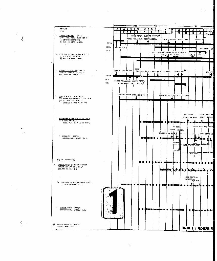
CONTRACT AIIiE~r~ SEIM QJT)D1. SIGNAL CONVERTER - QTYT. 2 ~AJ I . 1
(.DEFINE REQUIRCONTS 7X5 10)B SUBMIT NOR APRVL. RECEIVE APPRVL, SUBMIT FINAL DES. APPRNL, PKG1. SUBIMIT PPL
( b) EN G. FOR BESS. A PPLIC , DES ]IGN
DNT~t. REQUEST E..M PMUDUS ANPRUL. OF
TE STFOR'D GUESANACE PLANS TO TLO & NDNROPS
2. FIRE CDNTESL.SWITCTIADARD r QTY. 2___________ NRALý REV. A ZI. B RE C (U (I(a) DEFINE REQUIRERMIET9 4
I~ NG. FOR SEEN. ANFLIC.
3. PUESETTEE - TOREEO - QITY. 2 NOEL'Y. DATA TO NUDS 'UFINATE.API.N~ EEV NRL OSI F
CONTNDL PANEL RR 264 NMOD 0) FIA DEAlRR K.RCIV ERL. SBIENS. FNOR SERE. APeLIC. DESIG
DOR. IT AN AN
SUBMIT_ FO PPV RECIBA jPY
TORED NOOTSUjDa.622ATOMATIC OUPTN STUDY CX 13,032O.UTDALTS PUS ATT. NIR. MR I,/I(a) WIEUNI REQUIREMENT'S (STUDY EFFORTS)(b) BING. NOR SETTO. APPLIC.
(DELTED BMOST8 51050, 16 5)
ET
AT APPUV L. EQUIP ' SPEC .AN
5. DOUMENOTATION UOT NON! BUSIGR EQUNS SUNRI T RECEINE SBMNNT URCUIN00) SIEDAL CONVERTER Mimi 1mil u(M wirn '11lm iim f 10m '~1 .JLm I -(ELEG. FREQT. COONI. 19 S 5 UB MD( 0T
`+ 01* 1M4PAT ANPOL . t RUSUIIT DRAFT) HMS29A ATA
SUBMIT EUG N
(b) 'NESLI I-T) - TORPNEDONR SU . .. # OEOAP(CONTROL. PNEDL NE 2564 MOD00) INI EI Mimi Elni 1111 I 1 min E
URT I REV.
RECEIVE
SCO ANNOL. I
WIN IOOEVA'U VITOl EDUINTENl MIIUBIT'.l N WN ii i
SORVUAI: FIOR ANI. D)TR. ME 1/5
RAUGHT DRAFT MSSAVAD.LA I LI IS
(ITITOITCSTN TBTTKS ONLY) ml JINI glninisi U Mim 111111 11111111 tmE win, im 1~ ipi I,U los m11
.S oum. ELETNIFO IOEUSE Im viol 1mim $pi Ni. minMIM lmit joi ElmSYATRTSTEM iVIAL ,' SYSTERM T'ITTICR Mim viol ~m
C*) TETE-DYNARIIES DIN. EFFUORTCOVIRACT NOW' N 900) FIGURE 4-1 PROGRAM It

4A~
RE fiPAT LIST..
"REPAQWSID PARTSS.S
UO PPRL OPFL I TB SSE USDS
SHRTED OOALT (S C T D 5 SONAR SO. **PF #AT POS 000
DOC C (5) 0RECEIVE SUMT-RV U L EIAq OtS TA RTT N
.L VISEDTCAE-PPK KG-Wb
ROGH CMq APPVBL CYSUMT INTR 9VBF ORP FR
0 1 40Y Of LIMAS POOCUNDUTONAT' U SRLDS
.4 OU9DAF S A I týT .L S5 PRISENTEDCATOPI0ES, ART 5 WORK U
REV. 'GC E 3 P NT C P E , ATIRI in amini RITEED NGSS.
.# ROG DAT MOV AS.ADL REII''L SO OIS O RIrDCG5D R OE
TDP VL- I ~ ''~''I
INN NNI0 "loll P110110 COP11 GDle AR WRK
IlmIm.mimwni Ifimi isle ismli mini i 0rel
lip'1 11 .'mi 1 1000 'ii ssI tlwll1
VOL.~50 VOL.L IJL NAEAC O, VL
SF TOF PT, R
OS SOS.. BEL T BYYAC N ECS . C8,;7,0;
U 4.1 PROGRAM PtRFOlMANE CONTRACT j N40DUOS(S)679)I PAGE 1 I4LYISIS
~WAPPW4 STBW AW4 C""N,007ON

________________________________ 1980 1161J F M
IREPAIR PARTS LSTIU.REAR 'RT ()SESFOR: SUBMIT FINAVVL RECEIPT OF APPVL. (1
C. INLCNERTER S J(ELEC. FREQ. CONY. MIK 50 MOID 0)T T
(b) F.C. SWITCHBSOA~RDI I()PRESETTER-TORPED04 J j
(CONTROL PANEL ME 264 MORD 0) I- ~SUJBMIT FOR APP RECEIPTO APPOL.-
REPAI RPARTS LST
WITESS ACCEPTANCE TESTS
10. ENGINEERING SERVICES FOR; NORWEGAN 4Q IP.S
(A) LIAISON (WITH NORWEGIAN ROODU.S. NAVAL ACTIVITIES)1111111111111111111I1151 11111I 1111 lliiI111 11 11111
PAMILIARIZATIIN RFVLON EQUIP. ACCEPT. TROT PROCEDURES(Noo EGIA EQUIP.) (NOINEGEAS RPRIARED)
TATI- I-i- -
REVIEW NORWSEGIANE DIS.
DETERMEINEI I(B) NSTALATIN SINAL ONVETENCABLE DATA F
(5)INSALLTSVOINUS L OUTPURTSP FINAL (TENSE ONLO) RRV. I REV 61. 2
1NOV13I OF OTU S CNG&LYU
PREL'Y SYS.
FUNCTIONAL
D E 1036 &CBEDT
TRAINI1N1CLASSROOM RE IP35 11
DE 1036SHIPBOUARD RE 1035
'~PRVELTY COST. MOD.
FUNCTIGONAL SCHIEMATIC 111111111I11111 111 111I111111111111111151 3i usIII
(C) MISS11ýLE COPUNENT EVALUATIONMISL, QOOCR THRVOWN DEPTH1
CHOARGE OK 3 MID U)
(D) BIOAfLS-OPTEOFIIV EVA!. (DRIO35)TEChI. EVAL. (SANl DIEGO CALIF.) 11111liUPFTU FUR. COAL. (RIET WEST, FIA.)
A
(E) RERLATED STUDIESmi 111111111111111111 1111I1111ll1
(F) LAUNCII HADUG DISPLAYS (COOT. MOD. I13 # 1 6)DES IC14
'TESTS& DEL'Y. A~INSTALL,. ASSIST1
3:01P. LAUNGII RANCGE SLIDE RULOS;(CSONT. MOUR. 0 13 # 16 fA
0ES., 0EV. N V 003.
So 1 1 TIEI,-EOAOIICS DIV'. EPPOVY_______________________FIGURE 4-1 PROGRAM PER FORMANCE CONTRA

4-4
0 7 1 0 m D J F M A I M
@0REVIEW NORSEIS PREPARED:
111111 "" IUiII 1111 191111 111111 111111 91111 11111 Ipihl~ 11111 111111 . BEFAIR PARTS LIST
111111 1111111111111 111111IIIlII~ 111111 1111111111111 ~ .. ,.I2. ROTATING COMHPONENTS LIST
_ LA. 3. TUBE U. SUNS-CONS. LIST
I~ ~ I (1CLS. BK 37,11 TOU?)CABLE DATA I I IFINAL (TERSE INLY) REV. # I REV. #2 REV. 3 REV. # 4
111111 111 1111111 11 t llilIlflf11111 1111 111 1111111 Ilvl11111111I It. 11114111 11111111 11111111 N IWEIAI4G N ;LDAA IC BES:EQUIPMIENT FUNCTIONSSCHEMATICS
GEAR IA' S.
111ill~l~~ Il111111I11011111111I11 FERF'ORM SYSTEM CHECKSSB'.
FRUEL'T -cn MD LESS ITI NR 25 llll irnI
FINAL DATA (BNCL. TC MK 25)
1SUBMIT TACO. ETAL.FLAN TO BUDSS
FOOPOSED PIIL'T-OPUU'L, FIN1AL SFUR'L. TECH EVAL DATA REDIOTIPN (ASSIST TO HUGS)
oil' I11111 IINII 11111i 11111111111 TCH.RE'T
DATA PANEL PRETRLIL CONFERENCE TECIH. DITRII FC.EUI. O
A B cTON?. NBK 44/1, 2, 3, 4 & NMC 46/S
1111111 111111[111111 111111 I111111 '~ C -TERNSE III MISOSILE - APPLICATION TOIII~~ 1111FLEET V .ESSEL TYFES (DELETED BY MMOD0 I I NCL2*E
1PM II I LAUNCH RANGIE DISPLAY (2) (1/31/62)
REUET REEV DE.PO PVDB USIPj~LODL (2/2/AN) ;SETS
l~~~t11 DE
II -- IL & ICAop"l. PAMPHLET (2/2/62)
TROCT REQ'T. DWG. (;2/6/Z)TII',TYPE SRITCHEs 4/1/62
I111 llullm
fill~ll
1/3/62 TO LBNS
Jill ONET I I I
LI.KGl. (SUBMETTED FOR APPVIL)
C LATHERETTE PC. 1 ES ( TI)
A -PERFORMANCE CONTR C I I DATES 2MD OF SET
tAMý" "M PWAW 2 AvOaV2

DG-E53 1-323 Page 4-6
4.4 PROGRAM CONTROL
As can be seen from Figure 4-ZZ, administrative control of theprogram was centered in Engineering Operations, with full responsibilityfor program planning, scheduling manning and budgetary logistics vestedin the Naval Projects Section. The devices shown on this chart are rep-resentative of the controls used to assure efficient performance andaccomplishment.
4.5 PROGRAM PERSONNEL
Under the Naval Projects leadership of Mr. E. R. Behn, theArma program team responsibilities were as follows:
F. J. Romano - Development: System Integration and AnalysisNew design equipmentSpecificationsFATS
K. R. Mack - Installation: Equipment Integration and CablingSwitchboard RequirementsShipboard Installation andCheckout
System Documentation (SystemManual and FThictihniSb ie•e atic s)
BUWEPS Evaluation
D. R. Steen - Missile and Missile Component Evaluation
J. A. Bradford- Documentation: Instruction Books (NorwegianEquipment)
Instruction Books (Converter andTorpedo Presetter)
S.'-Taini'gFinal 2R.eport

.1 _ lii~17-7-
444
-71'
I4a 4
"ti Bu ~I-A 0$45.9 13___
4,. 1
10 i .1 * l.
FPj*M 14414 COTU - * .

*14 1
(Fx'equenlcy oflveZ'er MK 50 Md0
4- 1-LJT.E44
II 77
I V-
1~~~- IZ. ~1~>41AL -i 1.
04I
7 -- 1
Id * Legend
Li0brMtrG1~~I41~V 'I7Vi-7i~ -4.0_
77:7'
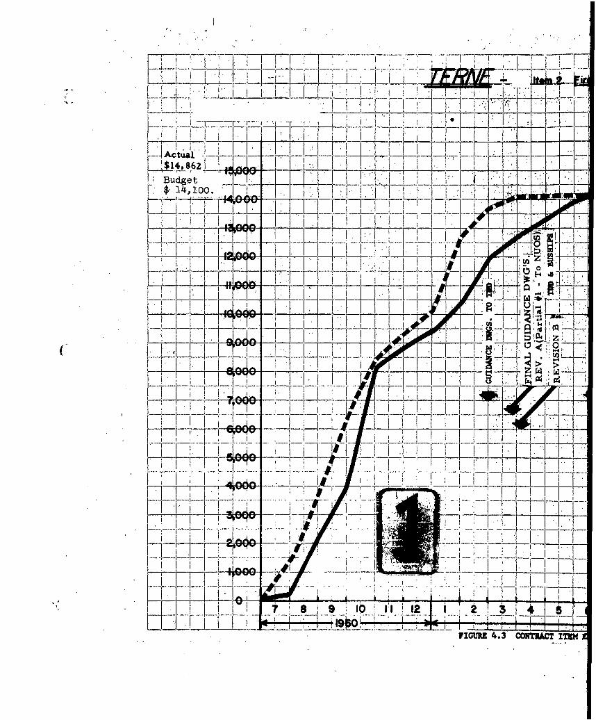
-Ata 1 7 1 -7 - F I I
I'o
LJ-J -'- 1L K' IL
-- i I li. i i • • i - i I .1- ...1/
i~j 7 .... 0
I 7 - I.
$--7 7t '.... .- '-
B u.e . ...-- -- _...
JI 71
_______~_4k_ A _ A _ _ j L__ _
9.-• 4 T-I...A-.. .0•' ' -i l77 _- -_ V. l--
S... .. .' . ... .. .. . ..._ !_ -I .. .... 7_ - •
zt~zzL ~ 7K. 4.0 o'o 'o
I <~~i KK~i7TT ~ J

-1F- JF
440e~~d0 ______1.---...- IJj 7 f
hi ii 1 7 1 1T .0!
ii~~= L . . -
I. I. g
T -4
II~/74
TT-=7 71- F Tz.
_j_ , ~1 _1- _ - -1 I -
!!!!T - -_- I -M _ _
1.3 ACT 1. IT SUfT'tLFrrI P. ESSEr, (,,, N Y,
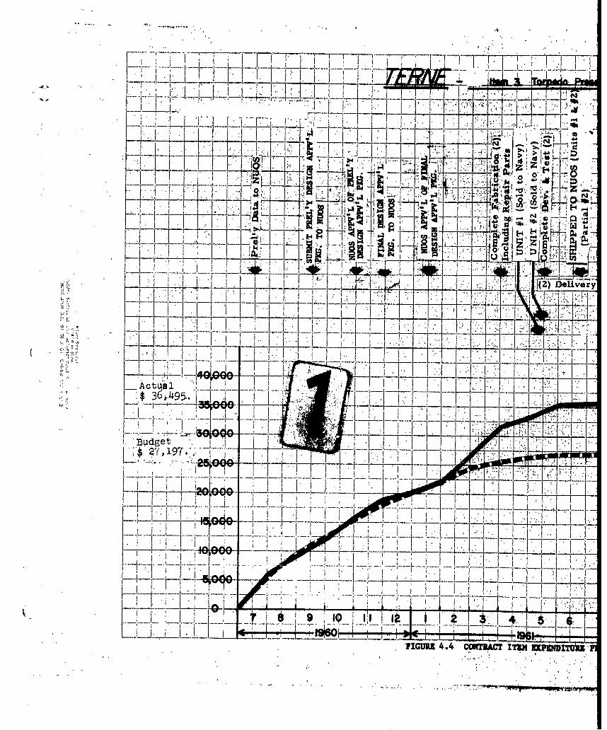
Jr I ''rV
7 -- - 4
I IJ
I~
z~
T-v--iK- : T 0
I ~~ I~i fft Dlvr
~ 2ff f 1
A c tua 1 I
-Ag e m etI
IItLLLJ -

(Cont rol Panel MK.264;Mod 0)
f__ 7 V.I I iii j~ ..;ý7`77-Iil
IIT 0I I týi7-ZT I
A Ii
ItT [ziF`~ .'
I Ijl I Actua' Labor :& aterhi~ea
71 1"
CONTRACT ITm UwUIITIT PLOTK ZUFFE L E19sc Go. f4 Y.
T wi.0, OWM PI

T I v . Da,
- I t.. . .e _ .
i F lI co U k* ' I : I _j... 7:
1 T 1i I 0
"-"1.-7 71...., 1 - .N , I ' -- i - . ... _
$ 3,-.105. ,
0..- -- ,• 1 I /,OI I 1II ' | . I i•r I' i i I " i i ! / t l o _$ I4
-,7 42 .....-r+ ... r T -- , _i
" [--- -, ---- -- -- -- ---- --
I._:_ __ __t
*.. -!-i~ .jI -i 7KV L
I... . I !-.OJ{O 11 1 -- ,, ,___
-I- -I ! t~i z z . I ,I --I I ! ....
7_ 7_1_
Actual-- __"_ _
FIGURE 4.5 cQNTRAcT iEM zxIgfmDITv

4-10
- I I
r1 -4
o. I k C
0 U 4)7 -
. ~ C7I7
.F-~ 7 I~-r
7- L
-~~ -- J,(SE Pata I5
T -
_TAC ITE ,XWTR PLOTS ~ II 1

T to.
2- - Ui0'*
C> ID r 7
114 4) 5)
-- ~~ - -.9 mz- o R. *.1U- 'd; 10~ F y~
o.i L.4
1$l9 F14 1
I~( . T 0I _4' 47-, i3
"FIUR 4. OIT4ATrV lPD
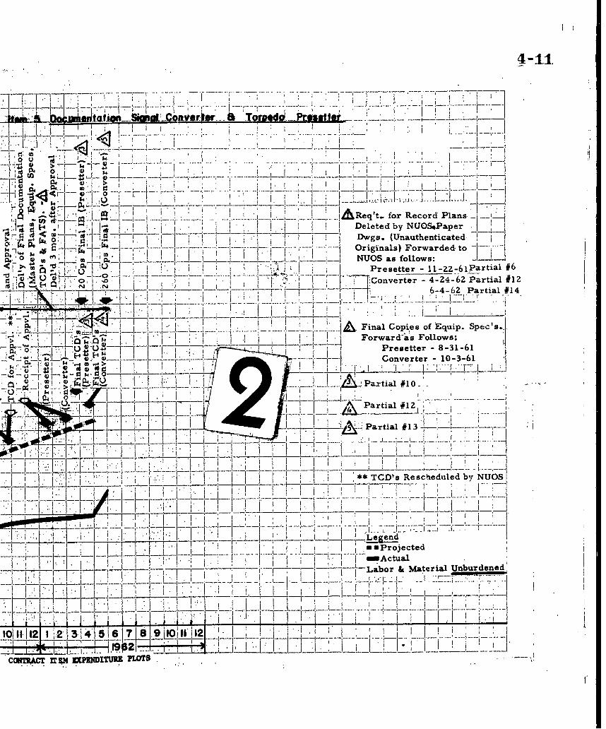
I1I~~i~~ii7 "d,...I..
In*
___....__A eqt for ecor Ulans.- ~ ~ ~ ~ ~ ~ ~ eee by--- - -.---------- - .-.---.
4 "17 as' ' -WOrgnas Forwarded.to0* 4. I I_ _ NUOS as follows:I Presetter - ll-ZZ-61partia1 #6
'I U '77,Converter-4-24-6Z Partial #1Z6-4-62 Partial #14
* ~ I AFinal Copies of Equip. Spec's.,
Forwarda's Follows:
Wj14Converter106
I ~~~~Partial #10 2 .
Iii Partial #13*1
~.:... II *TCD's RescheduledbNO
OR 7T1.4 I.L egendI' I umProjected
11 1 1fI~ I Labr &Material Unburdened'
_ Ijf 12
112- 11 1121.1J.ff1 "I -!!7_
COM7RACT rESM VPUDITUR3 PLOTS
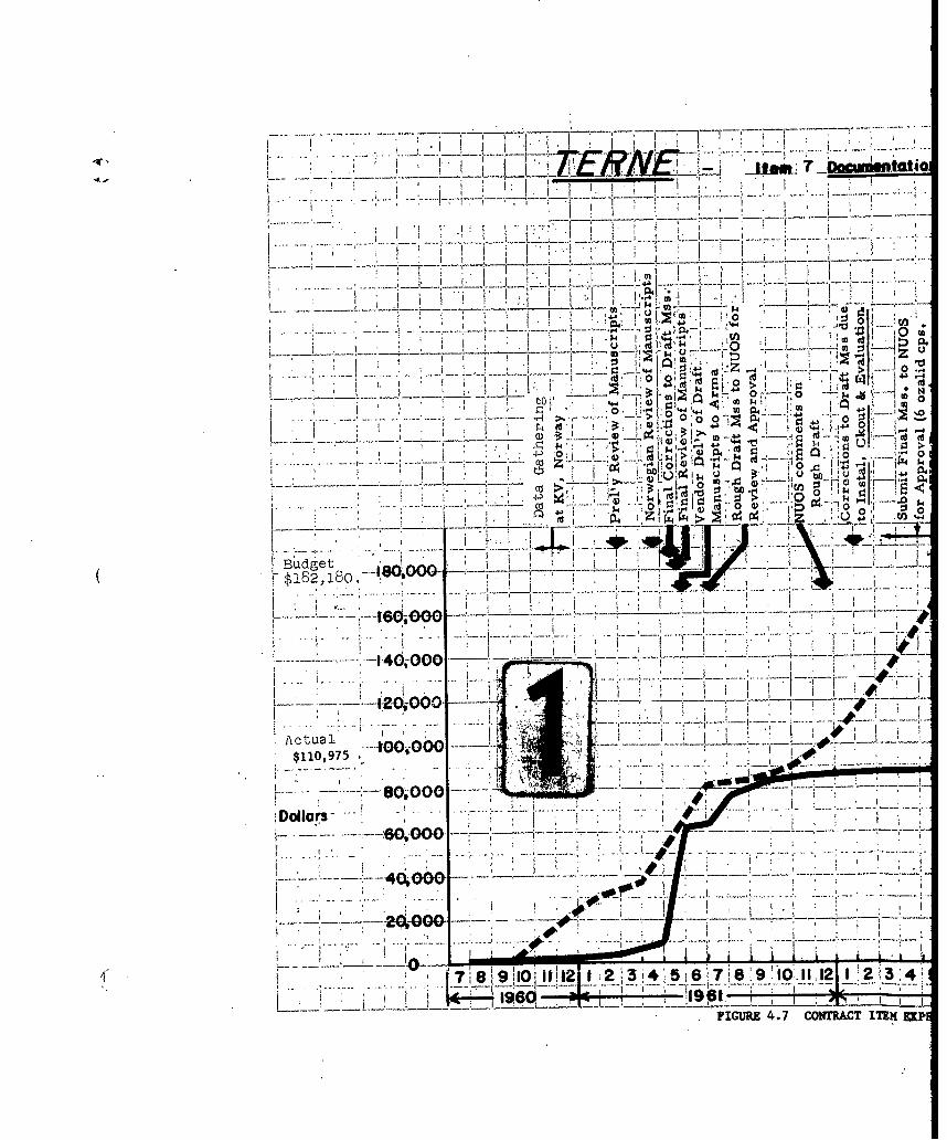
itl
I1 0, zrI~+
0 VI 0
0 00, o0
4) 4).
i ugt I ____(UK o I14 80 v80o0o0-0I
z' z
L -- 8.0,-000o~
Dollars---- 60.4D0O --- -4f-
------ ----
7-1 10 1 !2J341
FIGURE 4.7 CONTRAC~T ITEM EMKP
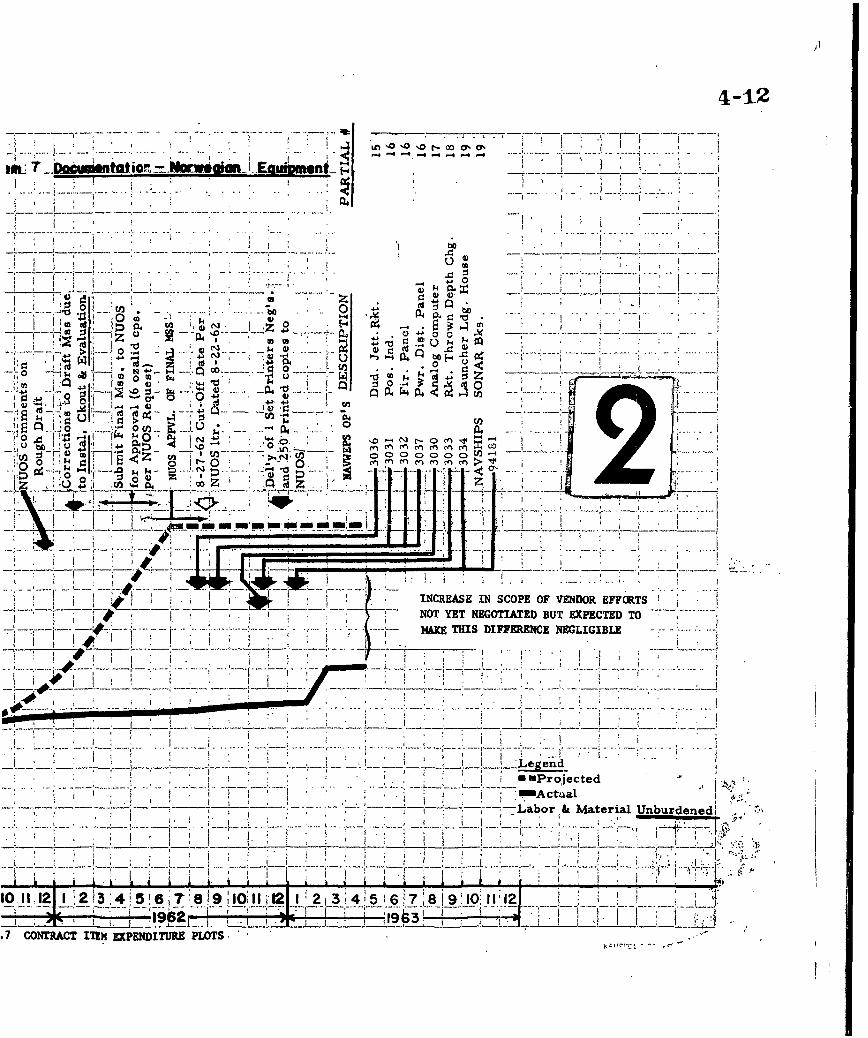
4-12
-L r- 00 a- 0,~ -
bO
o o
to to 044 4ý 4J bo-E
4 ~4- 4--~ 0D_ ._0 0to MU 4.;
m 18
0 44 04 0w
00 ~ 1 Id I'd- 0
km .m :r rm Ar 0r N V) 04
-#~P -,I
I _ _ _ _ I
INCREAS IN SCPEOFVEDOal FCNOT ~ Lbo YE MaterIAal UnburdenedDT
MM CONISC ITF1MC EXPENITUREPLOT40!t~~- . I

F TI T
IF4I~fK~dVKF~i7F-77
71-t 0 0~
VOLWS. I AND 11 AUH. 'TO PRDCXRD1IXTMHPuKp. OF FINAL.M8sPmIJBt L Imw2
Budget ____ i--K
T, 1 7
uar. L"I I
S* :. !10 If 10
Hat~u 8 W ATIM

4-13
8:lm tad O, 1-5104 ASW VUzaot SYS= M 3K1 MOD 0 VOL'S. 1, UIAM
:: I pF 1 -7', -77 - z Ir _7 - C-7 I.-.
7 F4- I I' I
-7~ T
7H~-7-7 T l CO~T
W~flID WITgo H 11
u-4 - - 4.3MK HSD1UNRiEIIL
ftIIIIIII~ a 7- 14 Z rI7I77~~ ~ ~ ~ 1 WI iLý. -)(
0~1~~i FV abo 0: Matoia Unbrdne
UIO~~i YI.Vt Th VVF
2/2 6Z~ ...X i lSE D M .CE~LESE O

.. ... . .
__J_ _
.64 0 0.4
41J , i
> $4
4)014)
54 41 4
(2 0
14)0
Budg~et . 4J
--6-000-- 0*
ActualjI
$3,618
78a.9 10l 1 2 1 2 3 4 5___ -ý06
FIGURE 4.9 CONTRACT ITEM EXPENDI

-t1mn 9 ivmvir. Parts, -fo. Converter..6 Prmffter
-4 -4
ft 4ý Cd1
.D4cd 4 .
ge, M. 0 0 .0
V . F4 04
0 4p
4N2 14 k, w
,, . -
ed --.--- --- - _ _
3 4ý 4J ~- . -
I . ICONTACTITEMEXPNDITRE LOT

-
, I ,IL '
% ilr. y
rail, rogra Lia 'son 'with ~
~V L owegian k UoS.S Naval Activitie
+4 1
PF-I Ik$55,6861
+tL _c- .... 0-
IR f A
9 10 111 0 X ý 1 2 3 4PaI~ so
FMO 410 OMCTIIW CaII-

4-15
INa 10A
r
71 . 1 -17
K-- . F,
:F___
06,-.. 7
17>. -
I il I ProjectedI I 1 iActual'
Labor & Matera n rde edl
-K II
H12 I2 4 5 6 7 is 9110 1 2 12 3,:4: 5. 718 9101 11 1._+
.19 9 ..1 193 2. :7
10D CONVMCT iIT4 PEMDITURE =S KEUFFEL &ESS9R CO. N Y.

" I, -i r,,•L ••• j-ii •°i ° r°•-,•
F Bu eIt
.___: I.. .-- _4A 7-", _.-
i:fJ 1 -- 4 --
Actual p f77$25193! -A oI - -.
-- -1, LL_ . 4._
I I I __--
-A I4 OT1 -(TERN NY TO LBNSYD
___ I t.I _ _w_
ELI -~ 1-I-.-
izz~. ' - __ -4i1--
FIGUR 4.1CNRC ITMEMP

0F 7
-' I
eeFl I
.11 CNTRAT ITM EXENDI~tE LOTS~ k ~S~Rr4. NV

t~ If
I __I ~JIJVffPartof:Item 1OB'
-Budget '- __ I$42,643L
---------------- 35i9 o 0 ----
> >
r_ __
- --- ---
_ _ I __J- '_ -J
-- ~~ 1-710 .
FIGUR 4.1 coNRAM I___ T- # E

.41I
0 ~ ~ * K-
> >
7__1
REVSE REPR COY(EST-I K3- QI.
CORETE T EFEC FNL V WG. ONUS LNI~1 t.__
4~ 0 1r
FO j9 9WO AND7p7IFT7 L
I ýActual
4.1 (4)RAC REPRM COPIESIM ADNLORTSK371E I

- L
I I A I .t.*
' I . I ,' ,;1 7 --77--i- ..
-�DE ET
2 ., I
- .1 T r, .I
_ I
j In
-AimT4.1 r If%^
-ý. .. D 135[ I
AA-
.4 --- --4 00-- . - - - -
77K1'.- TI~
_~~1 77 F i-rI_FIGUREJ. 4.1 'INTAC Im W

4-18'
0 :Itemn).OBI.LETh '1. II- '
I -I- -- -_--L~ :
_ ..... r i T lI-- , .,
__17 - F.F-I, •-
-I I-- - -
00 1 Actual.714.,..
ITEM CHECKS (DE 10325)-K
PERFORM SYSTEM CHECKS (DE 1036)
" II
f T_. 777 FII
-- ---- I-- 1 12 7E-
- *"I I ,I
_ _. _'" I i I ct a
3 .CONThT ITIM.] gND M PJI pL T S
V VQ-

- 7- - .- -, , I
. --- ---- i ..i
Part of:Iitem lOB
' +I
-0,- (d• - -0 bO
I . I .'P 4 7 -1J j * - - iIo I -
i , 6 . -- .. .......__-j__-___ !I.
... ... . . . _ _ • _ _ _•f._ _ _ *0
• _ [ _ _ ____ _-S... '__,... L__,_ _17..._--_-
-- -- T
0 o0
I,63 1 ^.d 14L
|/4
I----[--..-
i•
I_____ __-___
BudgetIU
.1O.Ti XJ
11. IF7 -i-- ~L
19i76~ -IuR
44 IoTRc iT~ ~

4-19:-t T--,--7-- --- r--i---r : - - --- 7 T-- -7•-"7--
- I - -iIT L
t of:I~te,., 1 _.•'•r,.L -_7 I____ __
J - .....i
_ _ _ I I ' ,•/ I r
'7-1-. ----T ----- ---- ---- . . -- ...
I- ir- ----- ___I. -! i-- . ....
-- z---F -• . .. ,... ... :... . !........ . .-4-.. ...... .-.. v- -. .. ,--- . . ..... -- -
J . . . . I .. 0i_ _ I -! _- -,I
"4.47 7 __ ._ _"_, ;_ ! .. '' .. _ I ! I I I_ I
T •. - I• .. I l - l - I !___-- •:].' I T -- __ !___ 1_._- - -' ,_
-T 7. ýw -- ; 1 "- 0 - -• .. -r- -F-.
0 0,-o *I,1 I____ __l _ L0 ..... -a
- -- 1 r - - --i4 ' / -- F
.. • J I 1
"__I_ '77 Ti7--lT--i ]--T-F--•• - F• II li -!01- -- :wl~ 7-7
, ', -]-~I-- - -I .... "
_ __I I I jLegend
___ III 0 umProjected
'1 7 iActual
or! Labor & Material Unburdened
----ieH ..S-I•- --!•--I-_ _-r - ... 1-- LIL • 1~ I_ __.___l-".... .... ,__
RTRACT ITE XEDITUJRE PLOTS ,UrrI, .rSSER C.. N y

-77-
+ +
EEII Prvd Minim--.--..-- En g. Coord into 1an Folo-U ofteMsie&M isl
7I
* . MisadsFllo-U ofb. tahle Missil & MNasale
Torpedo Station, Keyport, Wash.i
1 1-7-T 7j 7
-_F I' F -
Budge _7-7--
484

-- r T 7 F-T T F- 4-20
Am-I -- -- rn
. . . . . .....
iil1
- F
IGNITER TESTER I
'AM 'I NL A- -
jI ]ý27' - I
I __ I I[Ijq-it I I I i 1-99-
KNTACTITE EIEDT PLOT fFF &ESSE 00.- NY
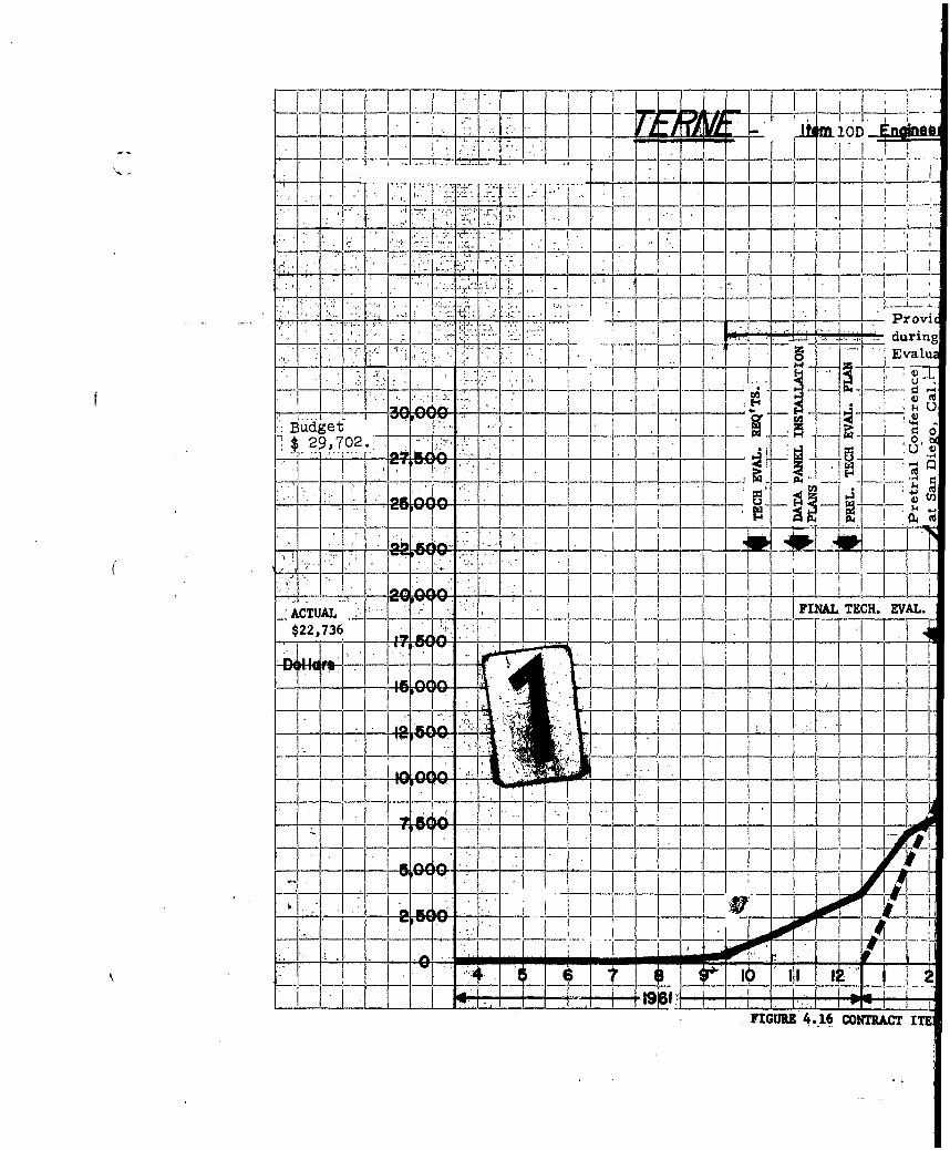
T-77-7
4.]_ _,_ _ _ _. _
'I ___l
Prerict." •lduring
Z EIVv777l.
7T ~ I
Budget f, o29,702 .•0-:-- -'.
__ --_ - - - •
-- ,- - -t7 V -
IF I~I.Z-VVH-V ~-~i-~--
$2A7.I E
FIA. - - • . . .E.. 1.Mfg.
-77_Q7--
FIGURE 4.16 coTRiACT ITE

4'-21
OD . t .u -I---1 - -7'
__ _, -. T. .---, -
I I , "i . . . .. . . i16D -- f--*--l - -T -
7-- . - . , . j-I
--- Provide Eng-g. Assistance '_-'-' • during BuWeps/OPTEVFOR .' ij i I . 1--- -
'• _ ._ DATA REDUCTION Assist to NUOS I TECH. REP'T.
S .o III -
0 1.b1oH 4) .1 . . -. . I -- -------4____ Q I 1 • ) . .. . ..7
-- , ..... _OPTEVFOR EVAL. (Key West, Fla.) DE 1035 -_ __--
- "-1- _-, _ I_---_
- .I� . ..... .... .
F I N L T C_ -*iVA L . P* * i* __ __,_ ..._._,. .....____...__"._j-- _I' j II
I F[1--- T - _ I T T Legend
-'~ rt ~~+ w a6 Projected-t-T-1 Act'ual
Labor & Material Unburdened
9E-2- 7.... r .. -.R 4.1. C&.... rE .... 2 -"----.-.. , ...... --i-

I...' " '- I. ... i . . . . . ., -.
L~ -- 0
_ Conduct Study Program: __ a/ Terne Depth Sonar .. .
Application to Fleet i:- : 0,•.Budget
1 Vessel Types. . •u .
I-7 12,439. 4, c/ Firing Doctrine &
!!. 1 F.C. Equip. for . <,- ,
Tj -Torp. hM44/l,2,,3 . 4 -
. ._ & MK46/0
I 77777-. $9, 507 •
-I--- - -.-
IF--, -F- - -
- - : ; !I _ _ . ..-TI
-.. ,-- ; !.• _ •_ : ! , _ ! ____! ---- .- -' - • • 1~
5 _! I -
__ _ JL ' FIGURE 4.17 COW!ATilIAGTIE[ U••~
t°

4-22
4-1- ----,1OEI l'anfrl_•iirivtLl-ý-"-l a ltild hwe.I...... --
•=, J J i , , . • L. I : I , , II* II. I I I !
S I N - ,-, I .I ., I • 0 -1 , • '' • ! : ' I •
] .. •, . ... . .,-, .
__ _+••@ -',il:..q .- .'..I .Y - .
-II I -flT T>'/::•:.," I' P
1~J~kN -- il I
____• .... i -- -F- IrI - -
.I -1
-,,- - I I _ _
I I1
- ' ----L -I - ' I. "I at
I.~~ ~j 44II_
I I I •_ ,. . .!. i. ... ... ._
t. { t ___ __
"- - - I T r 1- • - • 'ji--- -- -L-- -•---4---------.t , 11 I •..." '
lIT J T-7g.
T,,
7- Legend
I ~ I --- Labor & MAterial Unb~rdenell
_ _ -. ,
ICONTRACT ITEM SUE14ITURE PLOTS f.,FL&SE C

V mKK [ ~~~77 FrV ~ 7I ~ ~. i.-.-- -- job
I, I. I, S .
IV Tes Pj*.' _if~~03 ~ Ili 6) ,
4-~ -4:
F1 1 0 3 AIMD
IL
HTV1-7FIGRE4.8iIn= 71 [7M

to h itobe
Li1 I ij-~-.~-.~J. -HL3
i~ '-T-' 4~7V
------- -7
4-7 Legend --
-- -ý - -
- - -- t ib iiz 1~ 07-7-~I8-T CM4TR IT IV- P=)

F T, 4 4
7-~
UU)-4 ~ 4
o__ 4) I Vo )
I 4)
Biudget -*4,$ . 3,920~
'Actual I.4
$2, 988'-
Poom.,-
4 , ___ A
___ 3__ 4 _
10,O:1 7 aa ~t--T-
FIGURE 4.19 CONTRACT ITEM ZxpENDI

4-24
---- - ----
I , .
I .1 6
F17
COTITI I N IT M

TTT - ~ !!,1:777 11.ý, -r -7
t 0
1i
-4 .--
- - 4 - .~ ~:iloop.
-rw - -l..¼
-, I 01 . 23- -40 m;1LI
T. t 9 07< 19~L~hJ~iv
FiIr 4.0,.IR~oU
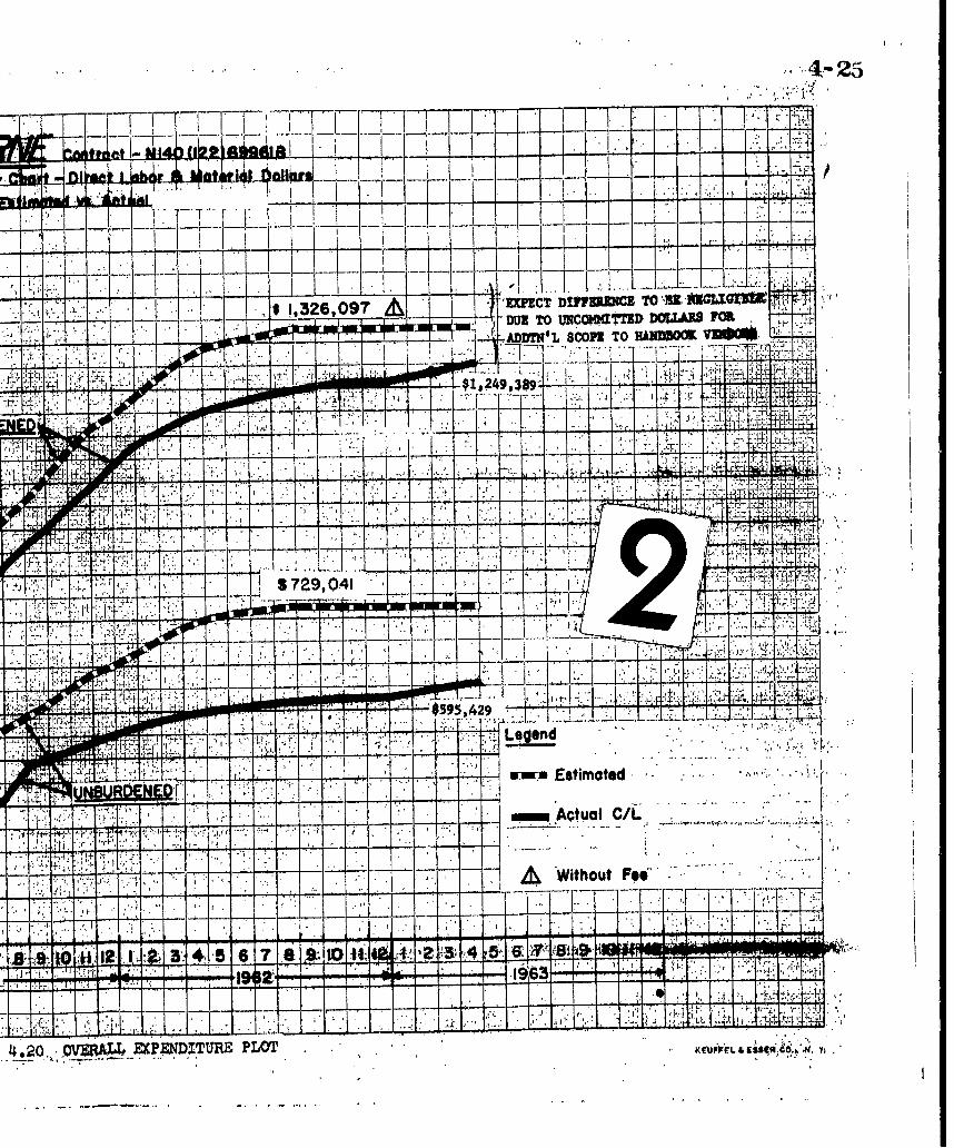
41- 23
1. 77 T1-
do-II ---- i- z -H- -4
-k.
& - - * ~~&ILA--
it'-
~'--729,0-1
wi w,*i*
I TF
h39 I 9J
7"r ~ ~ ~ Estimated
LLU1UwQWW Actual C/L
-v -~ AWithout Fe4-
-------------------------
* *. I
~j± .7ij7 PLOT .

4-26
.11
I ..
1-4II I. 4
I.-..., 00
-.4
- II
4.
I I L

0 Overdl Program Schedule
* Engineering Work Orders (interi
* Engineering Operating Work Sche
C NR Dollar Expenditure Records (mate
D Weekly Project Status Conferenc
B Commitment Trouble ReportsBudget Sheet
* Correlation Listing of EngineeringCode Assignments Operating Work Schedules (bimo
~stI~ates ni~nlllll iU~lllllllnllllllll n linnn• * Percent Completion Reports (himoEstlipates to. Complete
u Engineering Work Order Status R
IBM Cost Analysis 0 Schedule Commitment Reports (m
0 Rate vs Percent Completion Expe
* Workload Plots by Contract Item
* Monthly Project Status Reports
* Summary Plot: Manhour Expendit
* Summary Plot: Actual Dollar Ex
J, 1 Summary Plot; Planned Workload* Overall Program Liaison
FU 4
fr'"I
FIGURE 4.22 PI

4-27
Overall Program Schedule
Engineering Work Orders (interim budget allocations)
Engineering Operating Work Schedules
Dollar Expenditure Records (material dollars, travel and suksistence)
Weekly Project Status Conferences and Reports
Commitment Trouble Reports
Correlation Listing of Engineering Work Orders and Engineering Contract and Mods
Operating Work Schedules (bimonthly)Master Authorization and Revisions
Percent Completion Reports (bimonthly) Estimate Requests (aslrequired)
Engineering Work Order Status Reports (monthly) Estimate Requests (as required)
Schedule Commitment Reports (monthly) Budget (in conjunction with Controller's Dept.)
Rate vs Percent Completion Expenditure Pts by Contract Item (monthly) Deliveries
Workload Plots by Contract Item (monthly) Reports
Monthly Project Status Reports
Summary Plot: Manhour Expenditure vs Planned Workload
Summary Plot: Actual Dollar Expenditure vs Estimated Rate (unburdened)
Summary P!o9: Planned Workload
Overall Program Liaison
FIGURE 4.22 PROGRAM CONTROL

DG-E531-323 Appendix APage 1
Appendix A
LIST OF PRINCIPAL CONFERENCES:
12 November 1959 Arma at NUOS; Newport, R. I.
Purpose: To discuss general ground rules relative to Armaproposal for a study contract to define Norwegianand BUSHIPS-BUORD problem areas, in advanceof hardware contract.
18 November 1959 Arma at BUORD,, Re U4; Washington, D. C.
Purpose: To discuss the general Terne program and the Terneproposal document.
2 December 1959 Arrna at NUOS; Newport, R. I.
Purpose: To discuss study program description and salientdetails.
10 December 1959 Arma at BUWEPS; Washington, D. C.
Purpose: To review and discuss agenda for first visit to.Kongsberg, Norway.
11-20 December 1959 Arma at Kongsberg, Norway
Purpose: See paragraph 3.10.1, Contract item 10a.
31 December 1959 Arma at BUORD; Washington, D. C.
Purpose: To discuss preliminary Technical Development Plan.
8 January 1960 Arma/NUOS at BUWEPS and BUSHIPS; Washington, D.C.
Purpose: To discuss revisions to Terne "Technical DevelopmentPlan" with BUWEPS and BUSHIPS for purpose of includinginformation resulting from first visit to KV.

DG-E531-323 Appendix APage 2
15 January 1960 Arma at EUWEPS, Washington, D. C.
Purpose: To deliver documents (3) to NUOS at BUWEPS,Washington, D. C. (Phase Plan, TDP, Recom-mended Documentation for Weapon System W-113)
25 January 1960 Arma at ABAC; Washington, D. C.
Purpose: To brief Chicago Division representatives forpreparation of proposal to Arma Division for two(Z) switchboards, to discuss arrangements forPresetter requirements and Terne writeup forNavy Information Bulletin.
29 January 1960 Arma at BUWEPS-RUDC-3; Washington, D. C.
Purpose: To discuss Terne Development Program document(TDP).
I March 1960 Arma at Charleston Naval Shipyard, South Carolina
Purpose: To brief DE 1036 (McMorris) personnel with generaldetails of the Terne Program.
11 March 1960 Arma at BUSHIPS, Washington, D. C.
Purpose: To discuss progress of Terne Program in BUSHIPSand related matters.
23-28 March 1960 Arma at Kongsberg, Norway
Purpose: To exchange technical information between KV, Armaand U.S. authorities regarding technical problemsrelating to Arma's role in the installation of two Ternesystems aboard two U.S. vessels.
8 April 1960 Arma at BUSHIPS and BUWEPS; Washington, D. C.
Purpose: To obtain technical data on Terne Program and todiscuss ballistic computer for Torpedoes MK 43, 44, 46.

DG-E531-3Z3 Appendix APage 3
12 April 1960 Arma at NOTS; Pasadena, California
Purpose: To obtain firm presetting requirements for TorpedoesMK 44 and MK 46.
18 April 1960 Arma at Long Beach Naval Shipyard, California
Purpose: To discuss the Terne Program and Arma's role inthe installation of the Terne III system aboard DE 1035and DE 103'6; and preliminary planning and scheduling.
19 April 1960 NUOS at Arma
Purpose: To firm up requirements for the Torpedo Presetter.
2 May 1960 Arma at RUAW-31; Washington, D.C.
Purpose: To expedite processing of foreign visit clearancesfor Arma personnel to visit Kongsberg Vapenfabrikk.
20 May 1960 Arma at NOTS; Pasa.dena, California
Purpose: To discuss Torpedo Presetter and Ballistic Computerfor Torpedoes MK 43, MK 44, and MK 46, and Terneinterrelated areas.
Z6 May 1960 Arma at NOTS; Pasadena,, California
Purpose: To discuss Torpedo Presetter and Ballistic Computerrequirements and design concepts prior to preparationof technical proposal.
29 June 1960 Arma at NUOS; Newport, R. I.
Purpose: To establish an agenda for the July 11-28, 1960conference at KV.
5 July 1960 Tele-Dynamics Division at Arma
Purpose: To discuss matters pertaining to Arma preparationof switchboard guidance plans and related schedule
for T-DD switchboard contract with BUSHIPS.

DG-E531-323 Appendix APage 4
11-Z8 July 1960 Arma at Kongsberg, Norway
Purpose: To review functional flow diagram of complete systemand determine system cabling requirements and powerdistribution for system. Review installation drawingsand sonar requirements and determine requirementsfor logistic support. In addition: equiipment cooling,missile data, instruction books, system operation,drawings and documentation, and equipment tests werediscussed.
4 August 1960 NUOS at Arma
Purpose: To discuss technical and administrative details ooncerning:
1. Torpedo Presetter and Computer
2. SCB changes to DE 1035, DE 1036 re: Dash, YDS, andMk 37 Torpedo System
3. VDS corrections for attack application
4. Terne studies; vessel size, depth study
5. Handbooks
6. Attack Oirector Modifications
10 August 1960 Arma/NUOS at NOTS; Pasadena, California
Purpose: To redefine Torpedo Presetter requirements forTorpedoes MK 44 Mods 0 and 1 and to establish re-quirements for Torpedoes MK 44, Mods 2 and 3.
10 August 1960 Arma/NUOS at Long Beach Naval Shipyard, California
Purpose: To provide engineering assistance to LBNS for ShipAlt analysis.

DG-E531-323 Appendix APage 5
18-19 August 1960 Arma/NUOS at BUSHIPS; Washington, D. C.
Purpose: To review Terne Program and update BUSHIPS onresults of conferences at KV and LBNSYD.
30 August 1960 Arma at Long Beach Naval Shipyard, California
Purpose: To discuss Terne installation, cabling and power.
6 September 1960 Arma at NUOS; Newport, R. I.
Purpose: General technical discussion on all aspects of TerneProgram.
14- 15 September 1960 Arma at BUSHIPS and BUWEPS; Washington, D.C.
Purpose: General technical discussion of Terne Programrelative to conference at LBNSYD and current problems.
22 September 1960 Arma at NUOS; Newport, R. I.
Purpose: To review vendor handbook task, 'MIL-D-70327and obtain approval of Torpedo Presetter PreliminaryDesign Package.
27 September 1960 Arma at BUWEPS; Washington, D. C.
Purpose: To obtain approval of drawing formats as defined inMIL-D-70327.
29 September 1960 Arma at NUOS; Newport, R. I.
Purpose: General contractual discussion and clarification.
3 October 1960 Arma at Kongsberg, Norway
Purpose: General Terne technical conference.

DG- E531- 323 Appendix APage 6
11 October 1960 Arma at Long Beach Naval Shipyard, California
Purpose: Terne planning conference in preparation for visit ofKV engineers relative to KV assistance and generaltechnical discussions.
13 October 1960 Tele-Dynamics. Division at Arma
Purpose: To provide T-DD with advance information relativetý.; Switchboard Guidance Plans.
19 October 1960 Arma at NUOS; Newport, R. I.
Purpose: To review the approval status of Presetter and ConverterDesign Packages, Mark and Mod assignments, andNorwegian functional symbols.
19-20 October 1960 Arma at BUSHIPS; Washington, D.C.
Purpose: Conference to review the Arma-prepared SwitchboardGuidance Plans with BUSHIPS.
21 October 1960 Arma at NUOS; Newport, R. I.
Purpose: To discuss the Norwegian equipment handbook taskand to deliver computer run-out study reports.
25 October 1960 NUOS/Arma/KV at Long Beach Naval Shipyar&,Califo rnia
Purpose: Terne conference with KV and LBNSYD on generaltechnical and interface problems.
14-18 November 1960 Arma at Kongsberg, Norway
Purpose: To initiate Norwegian equipments instruction bookdata gathering effort.

DG-E531-323 Appendix APage 7
18 November 1960 Arma at NPO; Brooklyn, N. Y.
Purpose: General discussion and clarification of contract.
ZZ November 1960 Arma at"NUOS; Newport, R. I.
Purpose: To discuss various current problems, Torpedo MK 37Mod 1 engineering services, and Terne missile andfuze evaluation.
13-15 December 1960 Arma at Kongsberg, Norway
Purpose: Review status of data gathering effort; report of theperiod November 11, 1960 to December 9, 1960.
ZZ December 1960 Arma at BUWEPS and BUSHIPS; Washington, D. C.
Purpose: To review Norwegian visits of November and December,1960 and to discuss related technical areas.
9 January 1961 Arma at NUOS; Newport, R.I.
Purpose: General technical discussions. Agenda for nextKongsberg visit . Presetter increased scope.
17 January 1961 Arma at Tele-Dynamics Division; Philadelphia, Pa.
Purpose: General SWBD technical discussions.
25 January 1961 Bureau of Naval Personnel at Arna
Purpose: To review Arma preliminary planning and todiscussthe Terne Training Program in general.
26 January 1961 Tele-Dynamics Division at Arma
Purpose: To review impact of Torpedo MK 37-1 requirements
on switchboard.

DG -E531- 3Z 3 Appendix APage 8
27 January 1961 Arma at BUSHIPS, Code 665; Washington, D.C.
Purpose: To exchange general information relative to theswitchboard effort.
30 January 1961 Arma at Long Beach Naval Shipyard, California
Purpose: Toreview and analyze ShiipA-lt p-ro-býlýe-.m-s, and to discusspersonnel training program.
10 February 1961 Arma at NUOSj Newport, R.I.
Purpose: To discuss impact of adding Torpedo MK 37/1, andto review agenda for technical conference at KV,Norway, February 20 - March 3, 1961.
14-15 February 1961 Arma at BUWEPS~and BUSHIPS;-Wb-shington, D..C.
Purpose: Terne technical conference including discussions onprovisioning of spares, status of Terne equipmentsand sonar cabling.
15 February 1961 Tele-Dynamics Division at Arma
Purpose: To review Switchboard switching requirements forASW Weapon System MK 1 Mod 0.
28 February 1961 Arma at NUOS; Newport, R. I.
Purpose: To deliver the Final Design Approval Package for theElectronic Frequency Converter MK 50 Mod 0, and todiscuss missile evaluation programs.
21 February-2 March 1961 Arma/NUOS at Kongsberg, Norway
Purpose: To review sonar hoist and transducer installationdetails, final KV drawings, launcher and weather-hood installation. Reviewed additional informationfor technical manuals, synchro zeroing proceduresand schedules.

A-I
DGI-E531-323 Appendix APage 9
8 March 1961 Arma at NUOS; Newport, R. I.
Purpose: To report on discussions held at Kongsberg, Norway.
10 March 1961 Arma at BUWEPS and BUSHIPS; Washington, D. C.
Purpose: To review Kongsberg conference with Mr. J. Lacombe(BUWEPS) and Mr. Wagner (BUSHIPS).
13-14 March 1961 NUOS/T-DD and Arma at BUSHIPS; Washington, D.C.
Purpose: To review s"witchboard program and SwitchboardGuidance Plans for DE1035 and DE1036.
21 March 1961 Arma at BUSHIPS, Code 689; Washington, D.C.
Purpose: Review sonar cabling and wire designations.
24 March 1961 Arma at Tele-Dynamics Division; Philadelphia, Pa.
Purpose: To deliver latest switchboard drawings and to reviewrecent revisions.
12 April 1961 NUOS at Arma.
Purpose: Review approval of Switchboard Guidance Plans;Arma DG-E531-96, sheets 1 thru 4.
4-iTApril 1961 Arma at Kongsberg, Norway
Purpose: To review instruction book drafts and installation datawith KV, and establish installation requirements andengineering services required during training and in-stallation at Long Beach Naval Shipyard.
17-18 April 1961 Arma at NUOS; Newport, R.I.
Purpose: Review discussions held at Kongsberg.
ii

¶I
DG-E531-323 Appendix APage 10
1 May 1961 Arma at NUOS; Newport, R.I.
Purpose: Technical discussions relating to KV, presetter,presetter OCD's and MIL-Specs.
8 May 1961 Arma at Long Beach Naval Shipyard, California
Purpose: Discuss weatherhood and other data from KV conference.
15 May 1961 Arma at iNUOS; Newport, R. I.
Purpose: Technical discussions concerning instruction books,FATS, and progress at LBNSYD.
18 May 1961 Arma at T-DD; Philadelphia, Pa.
Purpose; Review of switchboard status and final correctionsto Switchboard Guidance Plans.
23 May 1961 Arma at BUWEPS and BUSHIPS; Washington, DC.
Purpose: Technical review of Terne program.
25 May 1961 Arma at NUOS; Newport, R. I.
Purpose: To discuss missile evaluation programs at Keyport,Washington; Dahlgren, Virginia; and NUOS, Newport.
25-Z6 May 1961 T-DD at Arma
Purpose: Review nomenclature for switchboard panel layouts.
30 May-i June 1961 Arma at Long Beach Naval Shipyard, California
Purpose: Pre-installation planning conference for exchange ofinformation.

DG-E531-323 Appendix APage 11
31 May - 9 June 1961 Arma/NUOS at Kongsberg, Norway
Purpose: To review production and acceptance test status,delivery schedule, shipping and packaging, finaldocumentation, and installation details.
7 June 1961 Arma/BUWEPS/NUOS at Dahlgren, Virginia
Purpose: Conference to discuss the technical details of the Ternemissile evaluation.
14 June 1961 Arma at NUOS; Newport, R. I.
Purpose: Planning conference relative to shipboard checkoutof Terne system.
19 June 1961 Arma at NUOS; Newport, R. I.
"Purpose: To re-submit the FAT for the Electronic FrequencyConverter MK 50/0, and to discuss the missile evalua-tion programs at Keyport and Dahlgren.
27 June 1961 Arma at Long Beach Naval Shipyard, California
Purpose: Discussion of training and KV services required duringinstallation.
12 July 1961 NUOS at Arma
Purpose: Discussion and review of Torpedo Presetter documenta-tion status.
14 July 1961 Arma at NUOS; Newport, R. I.
Purpose: Deliver one set of KV instruction books and proposedPPL. Discussed mechanical aid for over-the-sidetorpedoes.
3 August 1961 Arma at NUOS; Newport, R. I.
Purpose: Technical discussions concerning training and KV services.

PG-E531-323 Appendix APage 12
10 August 1961 Arrra at T-DD; Philadelphia, Pa.
Purpose: Discuss training at LBNSYD and switchboard status.
15 August 1961 Armas at BUWEPS and BUSHIPS; Washington, D. C.
Purpose: Review status of Terne -program.
Z0 August - 9 September 1961 Arma at Long Beach Naval Shipyard, Calif.
Purpose: Conducted classroom training program for vessel andshipyard personnel.
31 August 1961 Arma at Torpedo Station, Keyport, Washington
Purpose: To discuss the results of the first five firings of theTerne Exercise Rocket MK 4.
18 September 1961 Arma at NUOS; Newport, R. I.
Purpose: Discussion of instruction books and review of KVdocumentation.
27 September 1961 Arma at NUOS, Newport, R.I.,
Purpose: Discuss Keyport.preliminary firing results.
28 September 1961 Arma at NUOS; Newport, R. I.
Purpose: Review plans for BUWEPS shipboard evaluation ofTerne.
4 October 1961 Arma at NUOS; Newport, R. I.
Purpose: Discuss system book, and repair and maintenance data.
9-13 October 1961 Arma at LBNSYD, California
Purpose: To review installation progress and to provide engineeringassistance.

DG-E531 -323 Appendix APage 13
19 October 1961 Arma at NUOS; Newport, R. I.
Purpose: Review preliminary operational plans for BUWEPSshipboard evaluation of Terne.
25 October 1961 Arma at NUOS; Newport, R. I.
Purpose: Discussion of increased scope for mechanical aidsfor over-the-side torpedoes and system book.
30 October-14 December 1961 Arma at LBNSYD, California
Purpose: Provide engineering assistance during shipboardinstallation and checkout of Tern. system on DE 1035.
2 November 1961 - 2 April 1962 Arma at LBNSYD, California
Purpose: Provide engineering assistance during shipboardinstallation and checkout of Terne system on DE 1035and DE 1036.
7-10 November 1961 Arma at LBNSYD, California
Purpose: Deliver updated functional schematics, cable diagrams,and data panel cabling.
4 December 1961 Arma at NUOS; Newport, R.I.
Purpose: Discuss Launch Range Display Unit design approvalpackage, and the adequacy of the fuze test unit information,.
8 December 1961 Arma at NUOS; Newport, R. I.
Purpose: Discuss the technical evaluation.
18,21 December 1961 Arma at LBNSYD, California
Purpose: Discussions relative to shipboard training, and in-stallation problems.

DG-E531-323 Appendix APage 14
3 January 1962 Arma at NUOS; Newport, R. I.
Purpose: Review installation problems remaining on DE 1035and plans for BUWEPS Technical Evaluation.
5 January 1962 Arma at NUOS; Newport, R. I.
Purpose: Discuss Data Panel interfaces.
8-17 January 1962 Arma at LBNSYD, California
Purpose: Review status of Terne installation on DE 1035 andDE 1036.
24 January-17 February 1962 Arma at LBNSYD, California
Purpose: Provide engineering assistance during Terne installationand checkout on DE 1035 and DE 1036, and conduct class-room training program for DE 1036 personnel.
25 January 196Z Arma at Tele-Dynamics; Philadelphia, Pa.
Purpose: Review modifications required to UBFC Switchboardas determined during installation checkout aboard DE 1035.
27 February- 7 March 1962 Arma at Keyport, Washington
Purpose: To provide engineering assistance during alignmenttests of Terne system at Dabob Bay.
8, 9 March 1962 Arma at LBNSYD, California
Purpose: Review status of Terne installation on DE 1036.
9 March 1962 Arma at Dahlgren, Virginia
Purpose: To discuss Dahlgren Terne Missile Evaluation results.

IDG-E531-323 Appendix A
Page 15
10-25 March 1962 Arma at San Diego, California
Purpose: Provide engineering assistance during BUWEPSEvaluation of Terne on DE 1035.
26 March-4 April 1962 Arma at LBNSYD, California
Purpose: Provide assistance during final checkout of Ternesystem on DE 1036.
10 April 1962 Arma at NUOS; Newport, R. I.
Purpose: Discuss results of BUWEPS Technical Evaluation',data reduction, and deficiencies remaining in Ternesystem on DE 1035 and DE 1036.
16--27 April 1962 Arma at: (1) Long Beach Naval Shipyard, California(2) Naval Repair Facility; San Diego,
California
Purpose: To provide engineering assistance during shipyardavailability of DE 1035 (LBNSYD) and DE 1036 (NRF,San Diego). Replacement of OSS Synchro with newtype, 31 TR 6 ,in Computer MK 142.
17-18 April 1962 Arma at NUOS:; Newport, R. I.
Purpose: To discuss the NUOS program for analyzing BUWEPSTechnical Evaluation data.
24 April 1962 Arma at NUOS; Newport, R. I.
Purpose: To discuss Norwegian equipment maintenance datageneration and related topics.
2-3 May 1962 Arma at NUOS; Newport, R. I.
Purpose: To check preliminary results of BUWEPS TechnicalEvaluation data reduction at NUOS and programprogress.
DG -E531- 323 Appendix APage 16
10 May 1962 Arma at NUOS; Newport, R. I.
Purpose: To discuss plans and requirements for OPTEVFOROperational Evaluation.
11 May 1962 Arma at NUOS; Newport, R. I,
Purpose: To review problem areas relating to data reductionof BUWEPS Technical Evaluation data by NUOS.
31 May - 6 June 1962 Arma at TEVDET, Key West, Fla.
Purpose: Change computer underwater ballistics, check ofOSS synchro and Launch Range Display Unit, andassist in repair of Terne sonar transducer Train/
Tilt mechanism aboard DE 1035.
6-14 June 1962 Arma at: (1) LBNSYD, California"(2) NRF, San Diego, California
Purpose: Change computer underwater ballistics and provideengineering assistance relative to Terne installationon DE 1036.
13 June 1962 Arma/NUOS at Dahlgren, Virginia
Purpose: To discuss "Project Hero" (RF radiation hazard)results on Terne missile, and technical problemsconcerning the Terne fuze.
15 June 1962 Arma at NUOS; Newport, R. I.
Purpose: To discuss maintenance and repair, and spares pro-visioning for Terne equipments.
25 June - 20 July 1962 Arma at TEVDET; Key West, Fla.
Purpose: To provide engineering assistance during OPTEVFOREvaluation on DE 1035. Change Terne weapon patternspacing and run dynamic tests of overall system.
DI -E531- 323 Appendix APage 17
3 July 1962 Arma, NUOS, KV, and Dahlgren personnel atrBUWEPS; Washington, D. C.
Purpose: To discuss Terne Fuze technical problems relativeto Dahlgren Naval Weapons Laboratory findings.
9 August 1962 Arma at BUWEPS; Wa:<•n, D. C.
Purpose: Discuss OPTEVFOR Evaluation and BUWEPS plansfor maintaining the Terne system.
14 August 1962 Arma at NUOS; Newport, R. I.
Purpose: Summary meeting to review outstanding problems,including lack of KV maintenance data for equipmentmanuals and existing system design deficiencies.
23 August 1962 Arma at NUOS; Newport, R. I.
Purpose: To review outstanding technical problems includingobtaining information from KV and discuss Ternefinal report.
12 September 1962 Arma at NUOS; Newport, R. I.
Purpose: Discuss visit to KV for final status, and discussionof maintenance data.
11 October 1962 Arrna/NUOS/BUWEP personnel at NWL;Dahlgren, Va.
Purpose: To discuss the re-testing of the Terne fuzes for safetyevaluation.
26 October 196Z Armna at BUWEPS; Washington, D.C.
Purpose: Discuss operation of Terne sonar.
7 January 1963 Arma at NUOS; Newport, R. I.
Purpose: Discuss fuze test set and final project status.

IG-E53l- 3Z3 Appendix APage 18
15 March 1963 Arma at NUOS; Newport, R, I.
Purpose; Delivered wood mockup of launcher and loading house.
26 March 1963 Arma at NUOS; Newport, R. I.
Purpose: Discuss Arma evaluation report and final report
schedule.
10 April 1963 Arma at NUOS; Newport, R. I.
Purpose: Discuss draft of Terne final report.
I---

DG-E531-3Z3 Appendix B
I I I II
40
Pu o ' % 20 II IGsT a)jj
co 0 00j I 0 0 8 0
4,l r,,4 r. q OrZ ~ _____ .- NN N>I-~ 00,40~ U U U UoU Ulc '
oor 0 -1Z.
ws~t 0 0,404040 0 ,0 0 0 0, 0,t~ 01 NN NN N r*., N
0)6 (n Un W) u) u) )l U w) ) U / )
0 POP*0
U) UV m m ( l l m
a)) EU) (1) 4) ()4 ) attoJ
Pt 0)r, .1ý30 0l 0) 4, U) U) If6)u 9 9
-~ CY .~0 "E 0 0.
co .2z ~ v00
0 0 WU 0 (L
(.~ El d"1 tol~ . L__

DG-E531-323 Append~ix BPageZ2
0 7,s
0 y I II
m ul 0 w En U ) w 4 0 w ul(
w) m)~ Q A cn) m- -w(n wEp 1 ~~ 0t4 4
t%))) ) 4 4 ) 4) 44 0 0
§V P 1 1 1)l >1t 0 0
0?p 2 o 00 2 0 0 0 ) 0 r.00 Op 0 6
a) o04) D 4) 4) 4) a) 0 04a) 0 4)
Er w 4) 4))) m ) 4) 0 ) 4) 4)l 44 ul (n
Q)~4 4) a Q
>1 >,,>4)4)4n)" L 1 4 m ) 4)i En W ) m 4)) 4) 4
' te En 4) w 14 u)4 w) m U) v
K) a)4a)4) 4M) 4) (D 4 4 )) )
00t o 4)w J n l E l r
0 CC
10 o 0 mP4 ::4~ 00 CD
Sz 002 o ~ ~ 0 010~~~~ 0 0 ~
:0 co.- z0) 0 ro
0 0 A0C-
C:) 3 :'o to ~
() 4) 0 ..4 E
( _ _ _ _ _

LY i3Z3Appoi~dab BPage 3
0' (f 0
)W10
I 0SO I
, 0a 0 0
&0" 0 0 0 0 0
*SV,4 ) pe __ __f__ _ __
0 0 a 0 0 -
0 r. 0: r. r
o14w m 6ý - n -1 t 4 n QP-Er
a) D 0 0
0 06p 0 00
0oo , 019 w LO M 0 00,a ;0 0 D 0) 0
Z 0
0 d)0 0-u 0 0C 0 0 ). ~ 0 0 0 -
0 V 0 ~ . . A 'a 004 CY 0 0 (b 0 0 O 0~~~' '. 00 000
0 '~E ~ 0
00 00 0 0 o

-~. .323 Appencix B
'50 0
0 OV0
let, 7 :0~ c~i z~
0tL 0r 00 . tz 9
00 Do
00 410 -
0-0
do #v 0 0out,, olog 0
.0 Ptt vee CA Z
CA? 0A0
0A 0
w ~ ~ ~ r 'A ~
-rto 0 0~A
b,- PIN.~A
l% 'r fA 0 " 0
10 ;1 00-V S, r. kiI a -A -
.4c)
0)