L .2 194) UC-NRLF B 3 543 - Radio · time fuze Mk. UIA1 and the 30-second mechanical time fuze,...
40
Public Domain, Google-digitized / http://www.hathitrust.org/access_use#pd-google
Transcript of L .2 194) UC-NRLF B 3 543 - Radio · time fuze Mk. UIA1 and the 30-second mechanical time fuze,...

L
us
.2
194)
UC-NRLF
B 3 543
Genera
ted o
n 2
01
4-0
5-1
8 1
3:2
9 G
MT /
htt
p:/
/hd
l.hand
le.n
et/
20
27
/uc1
.b3
24
39
39
Public
Dom
ain
, G
oog
le-d
igit
ized
/
htt
p:/
/ww
w.h
ath
itru
st.o
rg/a
ccess
_use
#pd-g
oogle

Genera
ted o
n 2
01
4-0
5-1
8 1
3:2
9 G
MT /
htt
p:/
/hd
l.hand
le.n
et/
20
27
/uc1
.b3
24
39
39
Public
Dom
ain
, G
oog
le-d
igit
ized
/
htt
p:/
/ww
w.h
ath
itru
st.o
rg/a
ccess
_use
#pd-g
oogle
TM 9-1635
- WAR DEPARTMENT
/ c
r
^r
TECHNICAL MANUAL
t»-"
j»
ORDNANCE MAINTENANCE
'. FUZE SETTER, M8
FEBRUARY 8, 1941
Genera
ted o
n 2
01
4-0
5-1
8 1
3:2
9 G
MT /
htt
p:/
/hd
l.hand
le.n
et/
20
27
/uc1
.b3
24
39
39
Public
Dom
ain
, G
oog
le-d
igit
ized
/
htt
p:/
/ww
w.h
ath
itru
st.o
rg/a
ccess
_use
#pd-g
oogle

Genera
ted o
n 2
01
4-0
5-1
8 1
3:2
9 G
MT /
htt
p:/
/hd
l.hand
le.n
et/
20
27
/uc1
.b3
24
39
39
Public
Dom
ain
, G
oog
le-d
igit
ized
/
htt
p:/
/ww
w.h
ath
itru
st.o
rg/a
ccess
_use
#pd-g
oogle
TM 9-1635
c i
TECHNICAL MANUAL
ORDNANCE MAINTENANCE
FUZE SETTEB, M8
CHANGES } WAR DEPARTMENT,
No 1 J WASHINGTON, September 6,1941.
TM 9-1635, February 8,1941, is changed as follows:
2. Description.
*******
e. The setting mechanism * * * adjusting and setting rings.
***** * *
(2) For use with different types of fuzes, separate scales, setting
rings, and adjusting rings are furnished. Figures 11 and 12 show
the adjusting and setting rings for the 21-second aintiaircraft
time fuze Mk. UIA1 and the 30-second mechanical time fuze,
M43, respectively. For use with dummy fuze, M42, which
has no engaging pawls, an adjusting ring and brake ring
assembly (fig. 51/2) are provided. The function of the brake
ring is to impose a drag on the setting crank comparable to
that caused by the engaging pawls of the service rounds.
The elimination of the pawls and fuze rings for dummy prac-
tice without the addition of the braking device would allow
rotation of the operating crank with relatively no resistance.
Too rapid motion of the operating crank permits the stopping
pawl (B135294, fig. 8, sec. D-D) to drop off the cam surface
of the socket with such force that dents are made on the
undercut bearing surface of the socket (C69685). Too rapid
motion also results in severe wear and upsetting from pound-
ing of the rebound pawl (A43836) on the cam stop surface.
This upsetting has resulted in errors up to y10 second of fuze
setting. Damage to the chamfered slot on the gear (C69696)
results when the roller of the stopping pawl strikes the slot
rapidly. From figure 5V2 it can be seen that the braking
mechanism consists of a brake-lined clutch plate assembly on
the brake ring assembly which is held against the adjusting
ring by springs giving the required friction drag.
(3) An accessory chest is provided for carrying the rings, scales,
and spare electric lamps. The scale which is carried in the
chest should be wrapped in soft tissue when packing.
(4) For use in darkness * * * with luminous paint.
*******
[A. G. 062.11 (7-31-41).] (C 1, Sept. 6, 1941.)
6. Care and preservation.—a. Lubrication.— (1) At frequent
intervals swing fuze setter open and remove the adjusting and setting
rings. Clean rings thoroughly, lubricate pawls and guides with oil,
412320°—41
M558687
Genera
ted o
n 2
01
4-0
5-1
8 1
3:2
9 G
MT /
htt
p:/
/hd
l.hand
le.n
et/
20
27
/uc1
.b3
24
39
39
Public
Dom
ain
, G
oog
le-d
igit
ized
/
htt
p:/
/ww
w.h
ath
itru
st.o
rg/a
ccess
_use
#pd-g
oogle

Genera
ted o
n 2
01
4-0
5-1
8 1
3:3
0 G
MT /
htt
p:/
/hd
l.hand
le.n
et/
20
27
/uc1
.b3
24
39
39
Public
Dom
ain
, G
oog
le-d
igit
ized
/
htt
p:/
/ww
w.h
ath
itru
st.o
rg/a
ccess
_use
#pd-g
oogle

TM 9-1635
ORDNANCE MAINTENANCE
c i
o
o
o
c
o
Genera
ted o
n 2
01
4-0
5-1
8 1
3:3
0 G
MT /
htt
p:/
/hd
l.hand
le.n
et/
20
27
/uc1
.b3
24
39
39
Public
Dom
ain
, G
oog
le-d
igit
ized
/
htt
p:/
/ww
w.h
ath
itru
st.o
rg/a
ccess
_use
#pd-g
oogle

Genera
ted o
n 2
01
4-0
5-1
8 1
3:3
0 G
MT /
htt
p:/
/hd
l.hand
le.n
et/
20
27
/uc1
.b3
24
39
39
Public
Dom
ain
, G
oog
le-d
igit
ized
/
htt
p:/
/ww
w.h
ath
itru
st.o
rg/a
ccess
_use
#pd-g
oogle
TM 9-1635
FUZE SETTER, M8 C 1
lubricating, for aircraft instruments and machine guns (U. S. A.
Spec. 2-27), and coat the other surfaces with grease, special, low
temperature (Boyco 6A).
*******
(4) At regular intervals, the entire device should be disassembled
by ordnance personnel, all parts cleaned and lubricated and then
reassembled. Lubricate ball bearings with grease, special, low
temperature; use oil, lubricating, for aircraft instruments and
machine guns, on other moving parts.
*******
[A. G. 062.11 (7-31-41).] (C 1, Sept. 6. 1941.)
BY ORDER OF THE SECRETARY OF WAR:
G. C. MARSHALL,
Chief of Staff.
OFFICIAL:
E. S. ADAMS,
Major General,
The Adjutant General.
Genera
ted o
n 2
01
4-0
5-1
8 1
3:3
0 G
MT /
htt
p:/
/hd
l.hand
le.n
et/
20
27
/uc1
.b3
24
39
39
Public
Dom
ain
, G
oog
le-d
igit
ized
/
htt
p:/
/ww
w.h
ath
itru
st.o
rg/a
ccess
_use
#pd-g
oogle

Genera
ted o
n 2
01
4-0
5-1
8 1
3:3
0 G
MT /
htt
p:/
/hd
l.hand
le.n
et/
20
27
/uc1
.b3
24
39
39
Public
Dom
ain
, G
oog
le-d
igit
ized
/
htt
p:/
/ww
w.h
ath
itru
st.o
rg/a
ccess
_use
#pd-g
oogle

Genera
ted o
n 2
01
4-0
5-1
8 1
3:4
7 G
MT /
htt
p:/
/hd
l.hand
le.n
et/
20
27
/uc1
.b3
24
39
39
Public
Dom
ain
, G
oog
le-d
igit
ized
/
htt
p:/
/ww
w.h
ath
itru
st.o
rg/a
ccess
_use
#pd-g
oogle

Genera
ted o
n 2
01
4-0
5-1
8 1
3:4
7 G
MT /
htt
p:/
/hd
l.hand
le.n
et/
20
27
/uc1
.b3
24
39
39
Public
Dom
ain
, G
oog
le-d
igit
ized
/
htt
p:/
/ww
w.h
ath
itru
st.o
rg/a
ccess
_use
#pd-g
oogle
TM 9-1635
1-2
TECHNICAL MANUAL! WAR DEPARTMENT,
No. 9-1635 | WASHINGTON, February 8, 1941.
ORDNANCE MAINTENANCE
FUZE SETTER, M8
Prepared under the direction of the
Chief of Ordnance
Paragraph
General 1
Description 2
Operation 3
Disassembly and assembly 4
Tests and adjustments 5
Care and preservation 6
List of references 7
1. General.—a. Purpose.—This manual is published primarily for
the information and guidance of ordnance maintenance personnel.
b. Scope.—This manual supplements the technical manuals which
are prepared for the using arm. It contains descriptive matter and
illustrations sufficient to provide a general working knowledge of
the equipment and in addition contains information of use in the
maintenance and repair thereof by ordnance personnel.
c. References.—The Technical Manuals and Standard Nomencla-
ture Lists for the equipment described herein are listed in
paragraph 7.
d. Use.—The fuze setter, M8, is a mechanical device for manually
setting time fuzes of 3-inch antiaircraft ammunition in accordance
with data received from the director. It may be used with any
3-inch antiaircraft gun and mount firing ammunition fuzed with
the 21-second antiaircraft powder-train fuze Mk. Ill (and modifica-
tions) or with the 30-seconcl mechanical fuze, M43. Provision is
also made for use in drill practice with 3-inch dummy ammunition.
2. Description.—a. The fuze setter (figs. 1 to 10 incl.) is mounted
on the gun carriage by means of its attachment bracket. A short
length of 13-conductor cable (fig. 14) is included to provide the
283047°—41
Genera
ted o
n 2
01
4-0
5-1
8 1
3:4
7 G
MT /
htt
p:/
/hd
l.hand
le.n
et/
20
27
/uc1
.b3
24
39
39
Public
Dom
ain
, G
oog
le-d
igit
ized
/
htt
p:/
/ww
w.h
ath
itru
st.o
rg/a
ccess
_use
#pd-g
oogle

TM 9-1635
2
ORDNANCE DEPARTMENT
FUZE INDICATOR
FUZE R4N8E SCALE
ELECTRICAL INDEX (INNER)
MECHANICAL INDEX (OUTER)
FIUURE 1.—Fuze setter, MS. left side anil rear.
CABLE <!3-COND.)
CABLE RECEPTACLE
DUMMY' RECEPTACLE
EYEBOLT AND
WINS NUT
RA FSD 1209
-
FIGURE 2,—Fuze setter, M8, right side and rear,
Genera
ted o
n 2
01
4-0
5-1
8 1
3:4
7 G
MT /
htt
p:/
/hd
l.hand
le.n
et/
20
27
/uc1
.b3
24
39
39
Public
Dom
ain
, G
oog
le-d
igit
ized
/
htt
p:/
/ww
w.h
ath
itru
st.o
rg/a
ccess
_use
#pd-g
oogle

TM 9-1635
FUZE SETTER, M8
2
electrical connection between the fuze setter and the gun junction box
on the mount.
b. The fuze setter, M8, consists principally of the fuze indicator,
adjusting mechanism, and setting mechanism.
c. The fuze indicator includes a standard a. c. synchronous repeater
(C56701, fig. 7) mounted in the upper portion of the case.
(1) The electrical (inner) index (fig. 1) is mounted on the shaft
of the a. c. synchronous repeater.
RA FSO 1706
FIGURE 3.—Fuze setter, MS, open.
(2) The mechanical (outer) index, forming the other element of a
follow-the-pointer drive, is geared (1:1 ratio) to the adjusting
mechanism of the fuze setter. The fuze scale surrounding the me-
chanical index provides an indication of the fuze range.
(3) When the two indexes are matched, agreement between the
adjusting mechanism and the data received from the director is indi-
cated.
(4) The flexible cable (B137262) is provided with a standard 19-
pole receptacle for making the electrical connection between the gun
junction box on the mount and the fuze indicator.
3
Genera
ted o
n 2
01
4-0
5-1
8 1
3:4
7 G
MT /
htt
p:/
/hd
l.hand
le.n
et/
20
27
/uc1
.b3
24
39
39
Public
Dom
ain
, G
oog
le-d
igit
ized
/
htt
p:/
/ww
w.h
ath
itru
st.o
rg/a
ccess
_use
#pd-g
oogle

TM 9-1635
2
ORDNANCE DEPARTMENT
d. The adjusting mechanism, housed in the fixed part of the fuze
setter below the fuze indicator and geared thereto, contains the
adjusting ring (fig. 6), the pawls of which engage with the movable
(forward) ring of the fuze.
(1) The adjusting handwheel (B137241, fig. 9) mounted on the
shaft of the worm (B137242) rotates the gear (B137240) which is
attached to the adapter (C69694).
(2) On this adapter is mounted the adjusting ring assembly
which has pawls to engage with the ring of the fuze.
JH
FIGURE 4.—Fuze setter, M8, side view. (Sec. A-A is shown in fig. 6; sec. B-B in tig. 7;
sec. D-D in fig. 8; sec. H-H in fig. 10.)
e. The setting mechanism is located in the hinged part of the fuze
setter. The entire mechanism is pivoted on a hinge pin (A48270) to
permit ready separation from the fixed part of the fuze setter for
cleaning and for the removal or replacement of the adjusting and
setting rings.
(1) This mechanism contains the setting ring, the pawls of which
engage the fixed (rear) ring of the fuze and is driven by the setting
crank (C69689). By means of a ratchet-and-stop arrangement (fig.
8, sees. D-D and G-G), the setting crank is released when the trip
Genera
ted o
n 2
01
4-0
5-1
8 1
3:4
7 G
MT /
htt
p:/
/hd
l.hand
le.n
et/
20
27
/uc1
.b3
24
39
39
Public
Dom
ain
, G
oog
le-d
igit
ized
/
htt
p:/
/ww
w.h
ath
itru
st.o
rg/a
ccess
_use
#pd-g
oogle
TM 9-1635
2
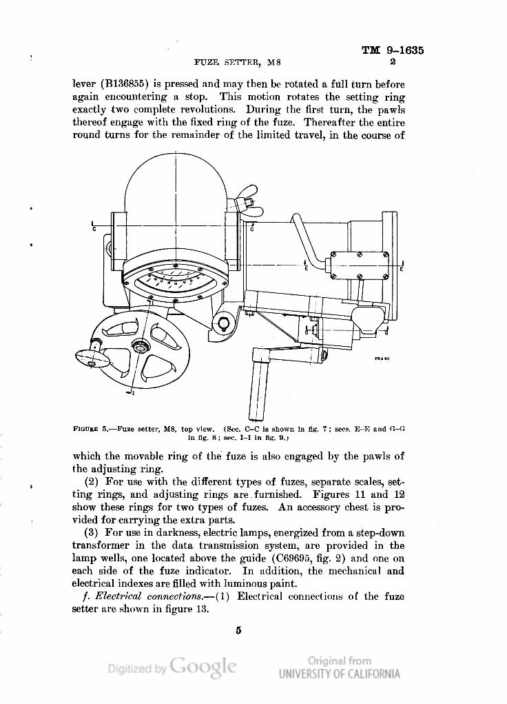
lever (B136855) is pressed and may then be rotated a full turn before
again encountering a stop. This motion rotates the setting ring
exactly two complete revolutions. During the first turn, the pawls
thereof engage with the fixed ring of the fuze. Thereafter the entire
round turns for the remainder of the limited travel, in the course of
FIGURE 5.—Fuze setter, M8, top view. (Sec. C-C is shown in fig. 7; sees. E-E and G-fi
in fig. 8; sec. I-I in fig. 9.)
which the movable ring of the fuze is also engaged by the pawls of
the adjusting ring.
(2) For use with the different types of fuzes, separate scales, set-
ting rings, and adjusting rings are furnished. Figures 11 and 12
show these rings for two types of fuzes. An accessory chest is pro-
vided for carrying the extra parts.
(3) For use in darkness, electric lamps, energized from a step-down
transformer in the data transmission system, are provided in the
lamp wells, one located above the guide (C69695, fig. 2) and one on
each side of the fuze indicator. In addition, the mechanical and
electrical indexes are filled with luminous paint.
/. Electrical connections.—(1) Electrical connections of the fuze
setter are shown in figure 13.
Genera
ted o
n 2
01
4-0
5-1
8 1
3:4
8 G
MT /
htt
p:/
/hd
l.hand
le.n
et/
20
27
/uc1
.b3
24
39
39
Public
Dom
ain
, G
oog
le-d
igit
ized
/
htt
p:/
/ww
w.h
ath
itru
st.o
rg/a
ccess
_use
#pd-g
oogle

TM 9-1635
2
ORDNANCE DEPARTMENT
Genera
ted o
n 2
01
4-0
5-1
8 1
3:4
8 G
MT /
htt
p:/
/hd
l.hand
le.n
et/
20
27
/uc1
.b3
24
39
39
Public
Dom
ain
, G
oog
le-d
igit
ized
/
htt
p:/
/ww
w.h
ath
itru
st.o
rg/a
ccess
_use
#pd-g
oogle

TM 9-1625
FUZE SETTER, M8
2
I
t-
Genera
ted o
n 2
01
4-0
5-1
8 1
3:4
8 G
MT /
htt
p:/
/hd
l.hand
le.n
et/
20
27
/uc1
.b3
24
39
39
Public
Dom
ain
, G
oog
le-d
igit
ized
/
htt
p:/
/ww
w.h
ath
itru
st.o
rg/a
ccess
_use
#pd-g
oogle

TM 9-1635
2
ORDNANCE DEPARTMENT
Genera
ted o
n 2
01
4-0
5-1
8 1
3:4
8 G
MT /
htt
p:/
/hd
l.hand
le.n
et/
20
27
/uc1
.b3
24
39
39
Public
Dom
ain
, G
oog
le-d
igit
ized
/
htt
p:/
/ww
w.h
ath
itru
st.o
rg/a
ccess
_use
#pd-g
oogle

TM 9-1635
FUZE SETTEE, M8
2
I jp
285047°—41 2
Genera
ted o
n 2
01
4-0
5-1
8 1
3:4
8 G
MT /
htt
p:/
/hd
l.hand
le.n
et/
20
27
/uc1
.b3
24
39
39
Public
Dom
ain
, G
oog
le-d
igit
ized
/
htt
p:/
/ww
w.h
ath
itru
st.o
rg/a
ccess
_use
#pd-g
oogle

TM 9-1635
2
ORDNANCE DEPARTMENT
SCREW- 8CCXIAA
SCREW-BCNX2CD-
WASHER-BEAXIH-
CLIP-A46M3
PIN-BFAXIDG
BOLT-BCAXICO
WASHER-BEAXIL-
NUT-BBAXIC
/SCREW-BCGX3FL
\_WASHER-BEAXIF
BRACKET-D29083
SECTION H-H
FIGURE 10.—Fuze setter, M8, section view. (See fig. 4 for location of section plane H-H.)
10
Genera
ted o
n 2
01
4-0
5-1
8 1
3:4
8 G
MT /
htt
p:/
/hd
l.hand
le.n
et/
20
27
/uc1
.b3
24
39
39
Public
Dom
ain
, G
oog
le-d
igit
ized
/
htt
p:/
/ww
w.h
ath
itru
st.o
rg/a
ccess
_use
#pd-g
oogle
TM 9-1635
FUZE SETTER, M8
2-3
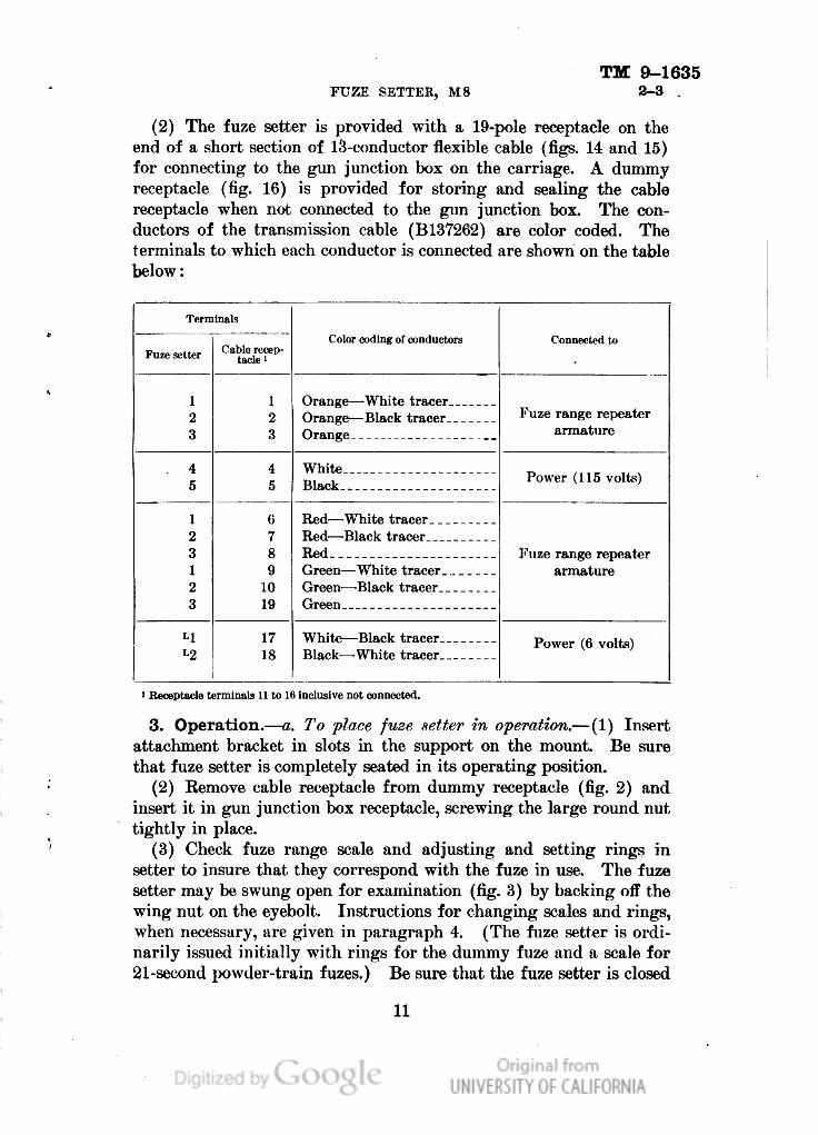
(2) The fuze setter is provided with a 19-pole receptacle on the
end of a short section of 13-conductor flexible cable (figs. 14 and 15)
for connecting to the gun junction box on the carriage. A dummy
receptacle (fig. 16) is provided for storing and sealing the cable
receptacle when not connected to the gun junction box. The con-
ductors of the transmission cable (B137262) are color coded. The
terminals to which each conductor is connected are shown on the table
below:
Terminals
Color coding of conductors
Connected to
Fuze setter
Cable recep-
tacle1
1
2
3
1
2
3
Orange — -White tracer
Orange — Black tracer
Fuze range repeater
armature
Orange
4
5
4
5
White
Power (115 volts)
Black ...
1
2
3
6
7
8
9
10
19
Red — White tracer
Red — Black tracer
Red
Fuze range repeater
armature
1
2
3
Green — White tracer _
Green — Black tracer
Green
Ll
17
18
White — Black tracer
Power (6 volts)
L2
Black — -White tracer
> Receptacle terminals 11 to 16 inclusive not connected.
3. Operation.—a. To place fuze setter in operation.—(1) Insert
attachment bracket in slots in the support on the mount. Be sure
that fuze setter is completely seated in its operating position.
(2) Remove cable receptacle from dummy receptacle (fig. 2) and
insert it in gun junction box receptacle, screwing the large round nut
tightly in place.
(3) Check fuze range scale and adjusting and setting rings in
setter to insure that they correspond with the fuze in use. The fuze
setter may be swung open for examination (fig. 3) by backing off the
wing nut on the eyebolt. Instructions for changing scales and rings,
when necessary, are given in paragraph 4. (The fuze setter is ordi-
narily issued initially with rings for the dummy fuze and a scale for
21-second powder-train fuzes.) Be sure that the fuze setter is closed
11
Genera
ted o
n 2
01
4-0
5-1
8 1
3:4
8 G
MT /
htt
p:/
/hd
l.hand
le.n
et/
20
27
/uc1
.b3
24
39
39
Public
Dom
ain
, G
oog
le-d
igit
ized
/
htt
p:/
/ww
w.h
ath
itru
st.o
rg/a
ccess
_use
#pd-g
oogle

TM 9-1635
3
ORDNANCE DEPARTMENT
i
SB
A
PIN-A48322B
PAWL-B137390
- SPRING-A43834
SECTION A-A
© Adjusting ring.
*-
PAWL-BI3739I
RING-C56670
PIN-A48289
FR.A 618
SPRING-A43834
PAWL-B 137392
PIN-A48322B
SECTION A-A
P1N-A48322A
PAWL- BI37393
RING-C5667I
PIN-A48289
FR.A.6I9
© Setting fing.
FIGDRB 11,—RliiRs for 21-second, antiaircraft, time fuze, Mk. IIIA1.
12
Genera
ted o
n 2
01
4-0
5-1
8 1
3:4
8 G
MT /
htt
p:/
/hd
l.hand
le.n
et/
20
27
/uc1
.b3
24
39
39
Public
Dom
ain
, G
oog
le-d
igit
ized
/
htt
p:/
/ww
w.h
ath
itru
st.o
rg/a
ccess
_use
#pd-g
oogle

TM 9-1635
FUZE SETTER, M8
3
P1N-A48322B
-SPRING-BI36534
SECTION A-A
PAWL-BI34658
PIN-A48289
RING-C69697
FR.A. 622
M
© Adjusting ring.
PIN-A48322B
SPRING-BI36534
PAWL-BI34659
RING-C69698
PIN-A48289
FR.A.623
SECTION A-A
® Setting ring.
FK:CRE 12.—Rings for 30-second, mechanical, time fuze, M43.
13
Genera
ted o
n 2
01
4-0
5-1
8 1
3:4
8 G
MT /
htt
p:/
/hd
l.hand
le.n
et/
20
27
/uc1
.b3
24
39
39
Public
Dom
ain
, G
oog
le-d
igit
ized
/
htt
p:/
/ww
w.h
ath
itru
st.o
rg/a
ccess
_use
#pd-g
oogle

TM 9-1635
3
ORDNANCE DEPARTMENT
14
Genera
ted o
n 2
01
4-0
5-1
8 1
3:4
8 G
MT /
htt
p:/
/hd
l.hand
le.n
et/
20
27
/uc1
.b3
24
39
39
Public
Dom
ain
, G
oog
le-d
igit
ized
/
htt
p:/
/ww
w.h
ath
itru
st.o
rg/a
ccess
_use
#pd-g
oogle

TM 9-1635
FUZE SETTER, M8
3
and the wing nut tightened before attempting to set fuzes or to lift
the fuze setter.
b. To set fuzes.—(1) Two operators are required,-one for the set-
ting mechanism and one for the adjusting mechanism. In addition,
certain operations are to be performed by personnel of the loading
detail.
(2) The operator (seated) of the adjusting mechanism continu-
ously keeps the mechanical (outer) index matched with the electrical
(inner) index regardless of whether a round is in the setter or not.
In lieu of matching indexes, he may instead set the mechanical
(outer) index to a desired indication on the fuze range scale in the
event that data is being provided other than through the electrical
transmission.
(3) The operator (standing) of the setting mechanism maintains
a light pressure on the setting crank in a counterclockwise direction.
_RECEPTACLE,I9 POLE .ASSEMBLY
C6942I
V, TERMINAL
"-£A4542I
(TO BE SOLDERED
ON WHEN ASSEM-
V, BLING CABLE TO
FUZE SETTER)
S
CABLE.TRANSMISSION
BI37262
FR.A.625
FIGURE 14.—Transmission cable.
As soon as the crank is free to move (after the trip lever has been
tripped by the loading detail personnel), he turns it one full turn
counterclockwise until a stop is encountered.
(4) The loading detail personnel inserts the round fully into the
setter, then momentarily depresses the trip lever, permitting the setting
operation to proceed; meanwhile, he exerts hand pressure downward
on the base of the cartridge case as long as the round remains in the
setter. When ready to use the round, he withdraws it from the setter,
being careful not to turn it until entirely disengaged from the setter
pawls.
c. Requirements •for proper setting of fuzes.—For the accurate set-
ting of fuzes, the following conditions must be fulfilled:
(1) That the round be placed into the fuze setter and forced down-
ward into full insertion before pressing the trip lever, and maintained
in that position by right-hand pressure on base end of case until
the "cut" is completed.
(2) That the trip lever be operated with a glancing blow so it will
be rearmed before the end of the crank stroke.
15
Genera
ted o
n 2
01
4-0
5-1
8 1
3:4
8 G
MT /
htt
p:/
/hd
l.hand
le.n
et/
20
27
/uc1
.b3
24
39
39
Public
Dom
ain
, G
oog
le-d
igit
ized
/
htt
p:/
/ww
w.h
ath
itru
st.o
rg/a
ccess
_use
#pd-g
oogle

TM 9-1635
3
ORDNANCE DEPARTMENT
(3) That the inner and outer indexes be kept matched at all times.
(4) That the setting crank be turned at the instant of release, and
rotation continued until it is definitely stopped by the stopping pawl
at end of the one-turn setting cycle.
(5) That the initial movement in withdrawing the round, after the
16
Genera
ted o
n 2
01
4-0
5-1
8 1
3:4
8 G
MT /
htt
p:/
/hd
l.hand
le.n
et/
20
27
/uc1
.b3
24
39
39
Public
Dom
ain
, G
oog
le-d
igit
ized
/
htt
p:/
/ww
w.h
ath
itru
st.o
rg/a
ccess
_use
#pd-g
oogle
TM 9-1635
FUZE, SETTER, M8
3-4
"cut" is completed, should be without rotation to avoid changing the
setting during the disengagement of the fuze from the pawls.
(6) That the pawls in the adjusting and setting rings be kept lubri-
cated and free of chips of metal, paint, or other foreign substances.
(7) That the operation and initial synchronization of the data trans-
mission system be correct.
d. To reset a fuze previously set.—Follow the same procedure as
given in 5 above for making the initial setting.
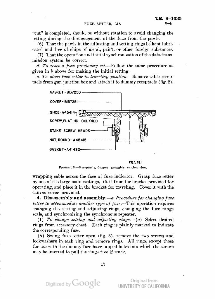
e. To place fuze setter in traveling position.—Remove cable recep-
tacle from gun junction box and attach it to dummy receptacle (fig. 2),
GASKET-BI37250
COVER-BI3725I
SHOE-A45414
SCREW, FLAT HD.-BCL.X4DD
STAKE SCREW HEADS
NUT, ROUND-A454I5—
GASKET-A4I482
FR.A.62I
FIGUHE 1C.—Receptacle, dummy, assembly, so.?tion view.
wrapping cable across the face of fuze indicator. Grasp fuze setter
by one of the large main castings, lift it from the bracket provided for
operating, and place it in the bracket for traveling. Cover it with the
canvas cover provided.
4. Disassembly and assembly.—a. Procedure for changing fuze
setter to accommodate another type of fuze.—This operation requires
changing the setting and adjusting rings, changing the fuze range
scale, and synchronizing the synchronous repeater.
(1) To change setting and adjusting rings.—(a) Select desired
rings from accessory chest. Each ring is plainly marked to indicate
the corresponding fuze.
(Z>) Swing fuze setter open (fig. 3), remove the two screws and
lockwashers in each ring and remove rings. All rings except those
for use with the dummy fuze have tapped holes into which the screws
may be inserted fro-pull the rings free if stuck.
17
Genera
ted o
n 2
01
4-0
5-1
8 1
3:4
8 G
MT /
htt
p:/
/hd
l.hand
le.n
et/
20
27
/uc1
.b3
24
39
39
Public
Dom
ain
, G
oog
le-d
igit
ized
/
htt
p:/
/ww
w.h
ath
itru
st.o
rg/a
ccess
_use
#pd-g
oogle
TM 9-1635
4 ORDNANCE DEPARTMENT
(c) Place new rings in position, inserting locating pins in holes
provided. These pins and the mounting holes are spaced so as to
render the two rings noninterchangeable. Keplace screws and lock-
washers, tightening screws securely. Check pawls to insure that
they operate freely.
(2) To change fuze range scale.— (a) Remove block inside lid of
accessory chest to obtain the other scale.
(b) Remove fuze indicator window frame (fig. 1), taking care not
to injure the gasket.
(c) Remove the six small screws exposed thereby and withdraw
clamping ring which encircles the scale. Remove scale, wrap it in
soft tissue paper and secure it in place behind block in accessory chest
lid.
(d) Place new scale with its outer rim in the groove and replace
clamping rings and screws just tightly enough to permit movement,
of the fcale for adjustment.
(e) Place a round in fuze setter, set fuze and slide scale around
to indicate the same value.
(/) To move scale, insert a blunt rod in hole above the zero grad-
uation. Verify setting, using several different values of fuze range,
tighten screws in clamping ring and check to see that both inner
and outer indexes clear without rubbing throughout a complete revo-
lution. Replace window frame.
(3) To synchronise repeater.— (a) The director and data trans-
mission system are to be connected and energized for this setting.
It is necessary that the director be fitted with the proper fuze range
dial for the fuze in use.
(b) Make necessary settings at the director to produce an indi-
cation of fuze range near mid-scale. Set the adjusting mechanism to
indicate the same value on the fuze indicator scale.
(c) If the inner and outer indexes are not matched, bring them
into alinement as follows:
1. For small adjustments, remove the cover from the right-
hand lamp well and, with a small screwdriver, turn the
slotted shaft projecting just above the lamp until the
inner index is alined with the outer index. Replace the
cover and screws. This motion is limited to approxi-
mately 35° in either direction from a central position.
2. For large adjustments, remove the window frame as when
changing scales, loosen the three screws (BCOX3BC)
in the clamping ring (A46116) and rotate the inner index,
pressing lightly with the fingers at two points 180° apart,
18
Genera
ted o
n 2
01
4-0
5-1
8 1
3:4
8 G
MT /
htt
p:/
/hd
l.hand
le.n
et/
20
27
/uc1
.b3
24
39
39
Public
Dom
ain
, G
oog
le-d
igit
ized
/
htt
p:/
/ww
w.h
ath
itru
st.o
rg/a
ccess
_use
#pd-g
oogle
TM 9-1635
FUZE, SETTER, M8 4-6
until it is alined with the outer index. Tighten the screws,
remove power, and check to insure that the inner index
rotates freely without rubbing or binding throughout a
complete revolution. Replace window frame.
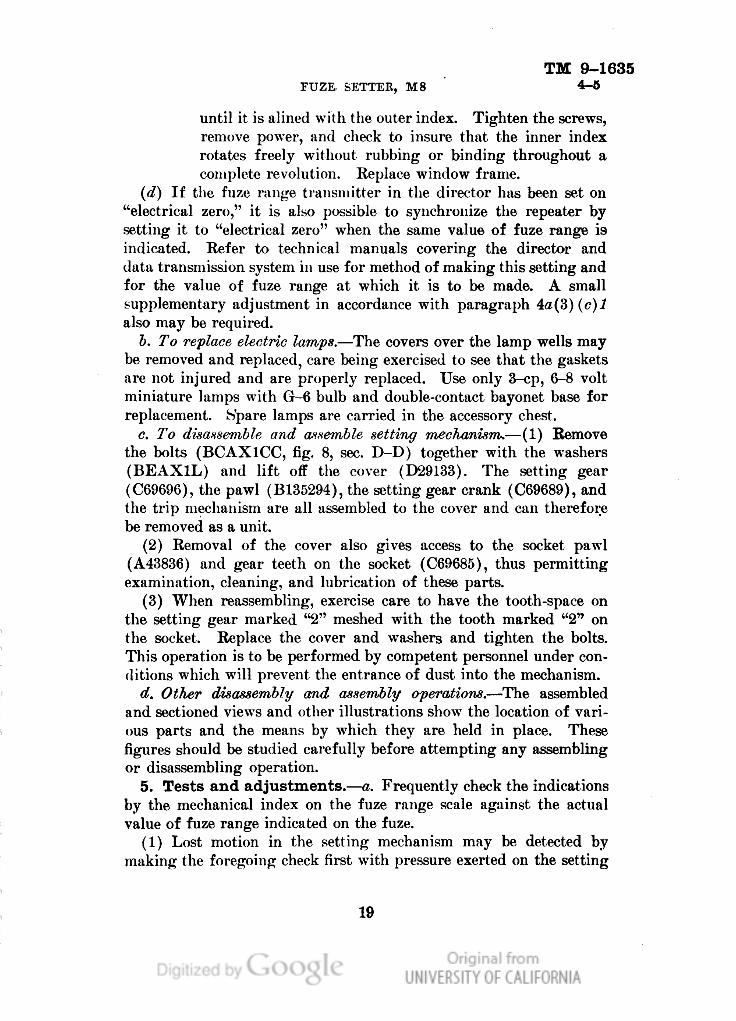
(d) If the fuze range transmitter in the director has been set on
"electrical zero," it is also possible to synchronize the repeater by
setting it to "electrical zero" when the same value of fuze range is
indicated. Refer to technical manuals covering the director and
data transmission system in use for method of making this setting and
for the value of fuze range at which it is to be made. A small
supplementary adjustment in accordance with paragraph 4a(3)(c)l
also may be required.
b. To replace electric lamps.—The covers over the lamp wells may
be removed and replaced, care being exercised to see that the gaskets
are not injured and are properly replaced. Use only 3-cp, 6-8 volt
miniature lamps with G-6 bulb and double-contact bayonet base for
replacement. Spare lamps are carried in the accessory chest.
c. To disassemble and assemble setting mechanism.—(1) Remove
the bolts (BCAX1CC, fig. 8, sec. D-D) together with the washers
(BEAX1L) and lift off the cover (D29133). The setting gear
(C69696), the pawl (B135294), the setting gear crank (C69689), and
the trip mechanism are all assembled to the cover and can therefore
be removed as a unit.
(2) Removal of the cover also gives access to the socket pawl
(A43836) and gear teeth on the socket (C69685), thus permitting
examination, cleaning, and lubrication of these parts.
(3) When reassembling, exercise care to have the tooth-space on
the setting gear marked "2" meshed with the tooth marked "2" on
the socket. Replace the cover and washers and tighten the bolts.
This operation is to be performed by competent personnel under con-
ditions which will prevent the entrance of dust into the mechanism.
d. Other disassembly and assembly operations.—The assembled
and sectioned views and other illustrations show the location of vari-
ous parts and the means by which they are held in place. These
figures should be studied carefully before attempting any assembling
or disassembling operation.
5. Tests and adjustments.—a. Frequently check the indications
by the mechanical index on the fuze range scale against the actual
value of fuze range indicated on the fuze.
(1) Lost motion in the setting mechanism may be detected by
making the foregoing check first with pressure exerted on the setting
19
Genera
ted o
n 2
01
4-0
5-1
8 1
3:4
9 G
MT /
htt
p:/
/hd
l.hand
le.n
et/
20
27
/uc1
.b3
24
39
39
Public
Dom
ain
, G
oog
le-d
igit
ized
/
htt
p:/
/ww
w.h
ath
itru
st.o
rg/a
ccess
_use
#pd-g
oogle
TM 9-1635
5-6 ORDXAXCE DEPARTMENT
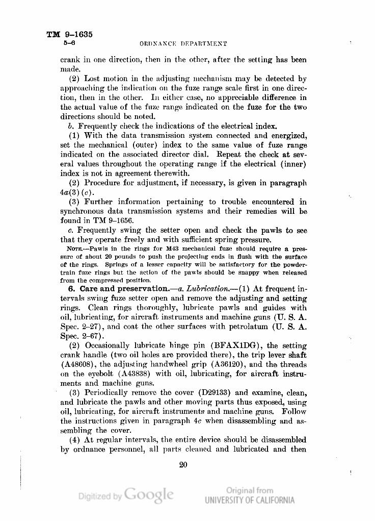
crank in one direction, then in the other, after the setting has been
made.
(2) Lost motion in the adjusting mechanism may be detected by
approaching the indication on the fuze range scale first in one direc-
tion, then in the other. In either case, no appreciable difference in
the actual value of the fuze range indicated on the fuze for the two
directions should be noted.
1). Frequently check the indications of the electrical index.
(1) With the data transmission system connected and energized,
set the mechanical (outer) index to the same value of fuze range
indicated on the associated director dial. Repeat the check at sev-
eral values throughout the operating range if the electrical (inner)
index is not in agreement therewith.
(2) Procedure for adjustment, if necessary, is given in paragraph
(3) Further information pertaining to trouble encountered in
synchronous data transmission systems and their remedies will be
found in TM 9-1656.
c. Frequently swing the setter open and check the pawls to see
that they operate freely and with sufficient spring pressure.
NOTE. — Pawls in the rings for M43 mechanical fuze should require a pres-
sure of about 20 pounds to push the projecting ends in flush with the surface
of the rings. Springs of a lesser capacity will be satisfactory for the powder-
train fuze rings but the action of the pawls should be snappy when released
from the compressed position.
6. Care and preservation. — a. Lubrication. — (1) At frequent in-
tervals swing fuze setter open and remove the adjusting and setting
rings. Clean rings thoroughly, lubricate pawls and guides with
oil, lubricating, for aircraft, instruments and machine guns (U. S. A.
Spec. 2-27), and coat the other surfaces with petrolatum (U. S. A.
Spec. 2-67).
(2) Occasionally lubricate hinge pin (BFAX1DG), the setting
crank handle (two oil holes are provided there), the trip lever shaft
(A48608), the adjusting handwheel grip (A36120), and the threads
on the eyebolt (A43838) with oil, lubricating, for aircraft instru-
ments and machine guns.
(3) Periodically remove the cover (D29133) and examine, clean,
and lubricate the pawls and other moving parts thus exposed, using
oil, lubricating, for aircraft instruments and machine guns. Follow
the instructions given in paragraph 4c when disassembling and as-
sembling the cover.
(4) At regular intervals, the entire device should be disassembled
by ordnance personnel, all parts cleaned and lubricated and then
20
Genera
ted o
n 2
01
4-0
5-1
8 1
3:4
9 G
MT /
htt
p:/
/hd
l.hand
le.n
et/
20
27
/uc1
.b3
24
39
39
Public
Dom
ain
, G
oog
le-d
igit
ized
/
htt
p:/
/ww
w.h
ath
itru
st.o
rg/a
ccess
_use
#pd-g
oogle
TM 9-1635
FUZE SETTER, M8 6-7
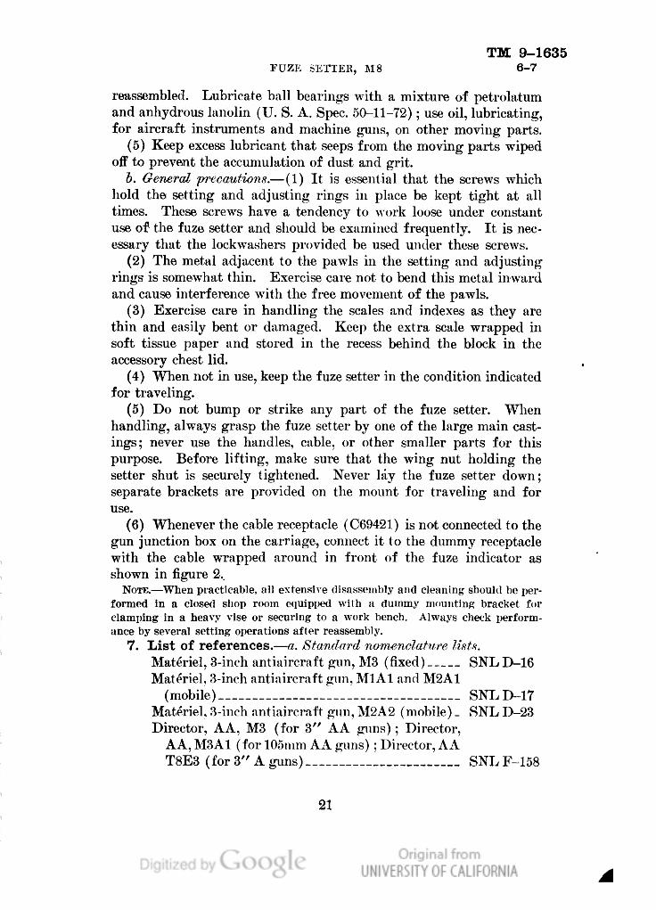
reassembled. Lubricate ball bearings with a mixture of petrolatum
and anhydrous lanolin (U. S. A. Spec. 50-11-72); use oil, lubricating,
for aircraft instruments and machine guns, on other moving parts.
(5) Keep excess lubricant that seeps from the moving parts wiped
off to prevent the accumulation of dust and grit.
6. General precautions.— (1) It is essential that the screws which
hold the setting and adjusting rings in place be kept tight at all
times. These screws have a tendency to work loose under constant
use of the fuze setter and should be examined frequently. It is nec-
essary that the lockwashers provided be used under these screws.
(2) The metal adjacent to the pawls in the setting and adjusting
rings is somewhat thin. Exercise care not to bend this metal inward
and cause interference with the free movement of the pawls.
(3) Exercise care in handling the scales and indexes as they are
thin and easily bent or damaged. Keep the extra scale wrapped in
soft tissue paper and stored in the recess behind the block in the
accessory chest lid.
(4) When not in use, keep the fuze setter in the condition indicated
for traveling.
(5) Do not bump or strike any part of the fuze setter. When
handling, always grasp the fuze setter by one of the large main cast-
ings; never use the handles, cable, or other smaller parts for this
purpose. Before lifting, make sure that the wing nut holding the
setter shut is securely tightened. Never lay the fuze setter down;
separate brackets are provided on the mount for traveling and for
use.
(6) Whenever the cable receptacle (C69421) is not connected to the
gun junction box on the carriage, connect it to the dummy receptacle
with the cable wrapped around in front of the fuze indicator as
shown in figure 2..
NOTE.—When practicable, all extensive disassembly and cleaning should be per-
formed In a closed shop room equipped with a dummy mounting bracket for
clamping in a heavy vise or securing to a work bench. Always check perform-
ance by several setting operations after reassembly.
7. List of references.—a. Standard nomenclature lists.
Materiel, 3-inch antiaircraft gun, M3 (fixed) SNL D-16
Materiel, 3-inch antiaircraft gun, MlAl and M2A1
(mobile) SNL D-17
Materiel, 3-inch antiaircraft gun, M2A2 (mobile) _ SNL D-23
Director, AA, M3 (for 3" AA guns); Director,
AA, M3A1 (for 105mm AA guns) ; Director, AA
T8E3 (for 3" A guns) SNLF-158
21
Genera
ted o
n 2
01
4-0
5-1
8 1
3:4
9 G
MT /
htt
p:/
/hd
l.hand
le.n
et/
20
27
/uc1
.b3
24
39
39
Public
Dom
ain
, G
oog
le-d
igit
ized
/
htt
p:/
/ww
w.h
ath
itru
st.o
rg/a
ccess
_use
#pd-g
oogle
TM 9-1635
7 ORDNANCE DEPARTMENT
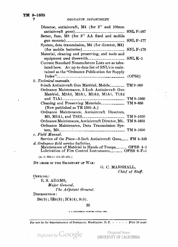
Director, antiaircraft, M4 (for 3" and 105mm
antiaircraft puns) SNLF-167
Setter, fuze, M8 (for 3" AA fixed and mobile
gun mounts) SNLF-177
System, data transmission, M4 (for director, M4)
(for mobile batteries) SNLF-179
Material, cleaning and preserving, and tools and
equipment used therewith SNLK-1
Current Standard Nomenclature Lists are as tabu-
lated here. An up-to-date list of SNL's is main-
tained as the "Ordnance Publication for Supply
Index"__ (OPSI)
b. Technical manuals.
3-inch Antiaircraft Gun Materiel, Mobile TM 9-360
Ordnance Maintenance, 3-Inch Antiaircraft Gun
Materiel, M2A2, M2A1, M1A2, M1A1, T1A2
and T1A1 TM 9-1360
Cleaning and Preserving Materials TM 9-850
(Now published as TR 1395-A.)
Ordnance Maintenance. Antiaircraft Directors,
M3, M3A1, and T8E3 TM 9-1650
Ordnance Maintenance, Antiaircraft Director, M4_ TM 9-1655
Ordnance Maintenance, Data Transmission Sys-
tem, M4 1 TM 9-1656
c. Field Manual.
Service of the Piece—3-Inch Antiaircraft Guns FM 4-125
d. Ordnance field service bulletins.
Maintenance of Materiel in Hands of Troops OFSB 4-1
Lubrication of Fire Control Instruments OFSB 6-F-l
[A. G. 062.11 (11-27-40).]
BY ORDER OF THE SECRETARY OF WAR:
G. C. MARSHALL,
Chief of Staff.
OFFICIAL:
E. S. ADAMS,
Major General,
The Adjutant General.
DISTRIBUTION:
B4(3);IR4(3);IC4(4),9(5).
22
For sale by the Superintendent of Documents, Washington, D. C. Price 10 cents
Genera
ted o
n 2
01
4-0
5-1
8 1
3:4
9 G
MT /
htt
p:/
/hd
l.hand
le.n
et/
20
27
/uc1
.b3
24
39
39
Public
Dom
ain
, G
oog
le-d
igit
ized
/
htt
p:/
/ww
w.h
ath
itru
st.o
rg/a
ccess
_use
#pd-g
oogle

Genera
ted o
n 2
01
4-0
5-1
8 1
3:4
9 G
MT /
htt
p:/
/hd
l.hand
le.n
et/
20
27
/uc1
.b3
24
39
39
Public
Dom
ain
, G
oog
le-d
igit
ized
/
htt
p:/
/ww
w.h
ath
itru
st.o
rg/a
ccess
_use
#pd-g
oogle

Genera
ted o
n 2
01
4-0
5-1
8 1
3:4
9 G
MT /
htt
p:/
/hd
l.hand
le.n
et/
20
27
/uc1
.b3
24
39
39
Public
Dom
ain
, G
oog
le-d
igit
ized
/
htt
p:/
/ww
w.h
ath
itru
st.o
rg/a
ccess
_use
#pd-g
oogle

Genera
ted o
n 2
01
4-0
5-1
8 1
3:4
9 G
MT /
htt
p:/
/hd
l.hand
le.n
et/
20
27
/uc1
.b3
24
39
39
Public
Dom
ain
, G
oog
le-d
igit
ized
/
htt
p:/
/ww
w.h
ath
itru
st.o
rg/a
ccess
_use
#pd-g
oogle

Genera
ted o
n 2
01
4-0
5-1
8 1
3:5
6 G
MT /
htt
p:/
/hd
l.hand
le.n
et/
20
27
/uc1
.b3
24
39
39
Public
Dom
ain
, G
oog
le-d
igit
ized
/
htt
p:/
/ww
w.h
ath
itru
st.o
rg/a
ccess
_use
#pd-g
oogle

Genera
ted o
n 2
01
4-0
5-1
8 1
3:5
6 G
MT /
htt
p:/
/hd
l.hand
le.n
et/
20
27
/uc1
.b3
24
39
39
Public
Dom
ain
, G
oog
le-d
igit
ized
/
htt
p:/
/ww
w.h
ath
itru
st.o
rg/a
ccess
_use
#pd-g
oogle

Genera
ted o
n 2
01
4-0
5-1
8 1
3:2
9 G
MT /
htt
p:/
/hd
l.hand
le.n
et/
20
27
/uc1
.b3
24
39
39
Public
Dom
ain
, G
oog
le-d
igit
ized
/
htt
p:/
/ww
w.h
ath
itru
st.o
rg/a
ccess
_use
#pd-g
oogle