
Sin título-2 - Logan Drilling Group · LOGAN DRILLING . LOGAN DRILLING . LOGAN DRILLING

DEEP HOLE DRILLING SYSTEMSSOLID CARBIDE TOOLS
botekEjector System
Deep hole drilling tools
Download and ordering information available on website
www.botek.de

2
The botek company
Manufacturing deep and precise holes is a technical challenge when processing metal. Accordingly specialising in deep hole drilling technology was the founding idea in 1974 of botek Präzisionsbohrtechnik GmbH in Riederich.
botek grew to be an international supplier of deep hole drilling tools. Over 500 employees in the main company develop and manufacture single and two fluted drills, deep hole drilling tools BTA and Ejector systems as well as special tools.
A complete product program, regarding all deep hole drilling aspects and a team of highly qualified and dedicated cutting specialists make botek a competent partner for the automobile industry and their suppliers, shipbuilding industry, hydraulic industry as well as motor, gear and machine building companies.
• Pleasenoteoursafetypointersatwww.botek.de
• OurGeneralStandardTermsandConditions,whichweassumeasknown,apply.
• Wereservetherighttomakemodificationsintheinterestsoftechnicalimprovement. Such modifications cannot, in principle, be accepted as justificable reasons for complaint.
• Subjecttochange.Themanufactureracceptsnoresponsibilityformisprintsandothererrors.
© botek Präzisionsbohrtechnik GmbH
3
botek – your expert partnerfor deep hole drilling tools
Contents
P. 12 The botek company
P. 12 Important information
P. 13 Contents
Tools
P. 14 Overview of types
P. 15 Areas of application
P. 16, 7 Deep-hole drilling - ejector system
Tool type 15
P. 18 Advantages
P. 19 Technical information
Tool type 60
P. 10 Advantages
P. 11 Technical information
Tool type 62
P. 12 Advantages
P. 13 Technical information
Tool type 70EP. 14 Advantages
P. 15 Technical information
Tool type 42
P. 16 Advantages
P. 17 Technical information
Tool type 43P. 18 Advantages
P. 19 Technical information
Tool type 13E
P. 20 Advantages
P. 21 Technical information
Tool type 35E
P. 22 Advantages
P. 23 Technical information
Type 55 outer/inner tubes
P. 24, 25 Outer and inner tubes
Ejector
P. 26, 27 Rotating connector
P. 28, 29 Non-rotating connector
P. 30, 31 Non-rotating connector
Ejector accessories
P. 32 Basic toolholder versions
P. 33 Vibration dampers, stationary tools
P. 34 Vibration dampers, (mechanically) rotating tools
P. 35 Guide bush/ Drill head setting gauge
Technical appendix
P. 36, 37, 38 Adjusting tools / cartridges - ordering information
P. 39 Ejector process
P. 40 Application on a lathe
P. 41 Application on a machining centre
Information
P. 42 Pilot hole /guide bush
P. 43, 44, 45 Cooling system
Application notes
P. 46, 47 Application notes
4
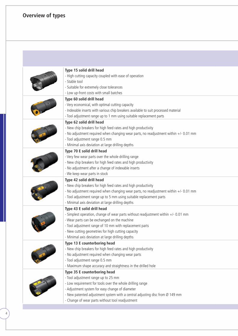
Type 15 solid drill head- High cutting capacity coupled with ease of operation- Stable tool- Suitable for extremely close tolerances- Low up-front costs with small batches
Type 60 solid drill head- Very economical, with optimal cutting capacity- Indexable inserts with various chip breakers available to suit processed material- Tool adjustment range up to 1 mm using suitable replacement parts
Type 62 solid drill head- New chip breakers for high feed rates and high productivity- No adjustment required when changing wear parts, no readjustment within +/- 0.01 mm- Tool adjustment range 0.5 mm- Minimal axis deviation at large drilling depths
Type 70 E solid drill head- Very few wear parts over the whole drilling range- New chip breakers for high feed rates and high productivity- No adjustment after a change of indexable inserts-Wekeepwearpartsinstock
Type 42 solid drill head- New chip breakers for high feed rates and high productivity- No adjustment required when changing wear parts, no readjustment within +/- 0.01 mm- Tool adjustment range up to 5 mm using suitable replacement parts- Minimal axis deviation at large drilling depths
Type 43 E solid drill head- Simplest operation, change of wear parts without readjustment within +/- 0.01 mm-Wearpartscanbeexchangedonthemachine- Tool adjustment range of 10 mm with replacement parts- New cutting geometries for high cutting capacity- Minimal axis deviation at large drilling depths
Type 13 E counterboring head- New chip breakers for high feed rates and high productivity- No adjustment required when changing wear parts- Tool adjustment range 0.5 mm- Maximum shape accuracy and straightness in the drilled hole
Type 35 E counterboring head- Tool adjustment range up to 25 mm- Low requirement for tools over the whole drilling range- Adjustment system for easy change of diameter- New patented adjustment system with a central adjusting disc from Ø 149 mm- Change of wear parts without tool readjustment
Overview of types
5
Type 15 solid drill head- High cutting capacity coupled with ease of operation- Stable tool- Suitable for extremely close tolerances- Low up-front costs with small batches
Type 60 solid drill head- Very economical, with optimal cutting capacity- Indexable inserts with various chip breakers available to suit processed material- Tool adjustment range up to 1 mm using suitable replacement parts
Type 62 solid drill head- New chip breakers for high feed rates and high productivity- No adjustment required when changing wear parts, no readjustment within +/- 0.01 mm- Tool adjustment range 0.5 mm- Minimal axis deviation at large drilling depths
Type 70 E solid drill head- Very few wear parts over the whole drilling range- New chip breakers for high feed rates and high productivity- No adjustment after a change of indexable inserts-Wekeepwearpartsinstock
Type 42 solid drill head- New chip breakers for high feed rates and high productivity- No adjustment required when changing wear parts, no readjustment within +/- 0.01 mm- Tool adjustment range up to 5 mm using suitable replacement parts- Minimal axis deviation at large drilling depths
Type 43 E solid drill head- Simplest operation, change of wear parts without readjustment within +/- 0.01 mm-Wearpartscanbeexchangedonthemachine- Tool adjustment range of 10 mm with replacement parts- New cutting geometries for high cutting capacity- Minimal axis deviation at large drilling depths
Type 13 E counterboring head- New chip breakers for high feed rates and high productivity- No adjustment required when changing wear parts- Tool adjustment range 0.5 mm- Maximum shape accuracy and straightness in the drilled hole
Type 35 E counterboring head- Tool adjustment range up to 25 mm- Low requirement for tools over the whole drilling range- Adjustment system for easy change of diameter- New patented adjustment system with a central adjusting disc from Ø 149 mm- Change of wear parts without tool readjustment
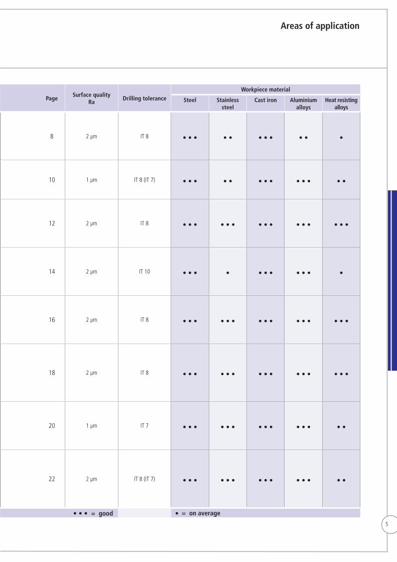
PageSurface quality
RaDrilling tolerance
Workpiece material
Steel Stainless steel
Cast iron Aluminium alloys
Heat resisting alloys
8 2 µm IT 8 ··· ·· ··· ·· ·
10 1 µm IT 8 (IT 7) ··· ·· ··· ··· ··
12 2 µm IT 8 ··· ··· ··· ··· ···
14 2 µm IT 10 ··· · ··· ··· ·
16 2 µm IT 8 ··· ··· ··· ··· ···
18 2 µm IT 8 ··· ··· ··· ··· ···
20 1 µm IT 7 ··· ··· ··· ··· ··
22 2 µm IT 8 (IT 7) ··· ··· ··· ··· ··
Areas of application
= good··· = on average·
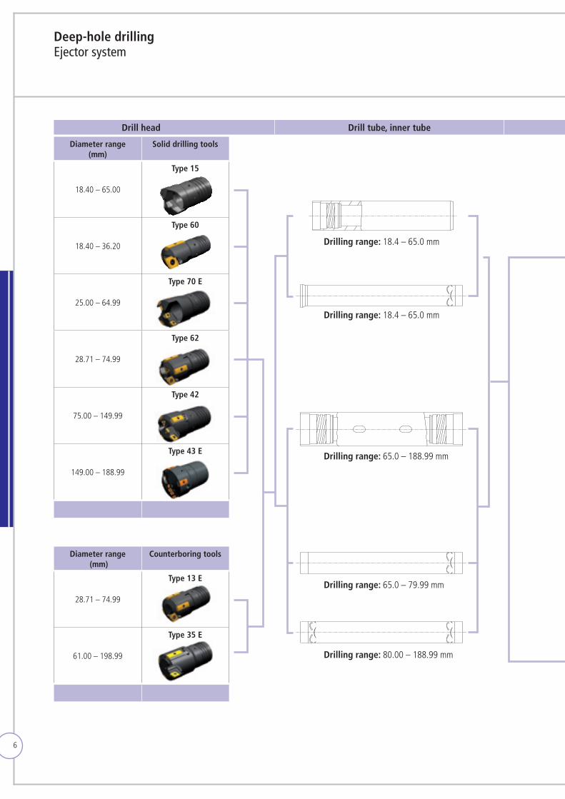
Deep-hole drilling Ejector system
6
Diameter range (mm)
Solid drilling tools
18.40 – 65.00
Type 15
18.40 – 36.20
Type 60
25.00 – 64.99
Type 70 E
28.71 – 74.99
Type 62
75.00 – 149.99
Type 42
149.00 – 188.99
Type 43 E
Diameter range (mm)
Counterboring tools
28.71 – 74.99
Type 13 E
61.00 – 198.99
Type 35 E
Drilling range: 18.4 – 65.0 mm
Drilling range: 18.4 – 65.0 mm
Drilling range: 65.0 – 188.99 mm
Drilling range: 80.00 – 188.99 mm
Drilling range: 65.0 – 79.99 mm
Drill head Drill tube, inner tube Vibration damper Collet Sealing sleeve Connector Basic toolholder
7
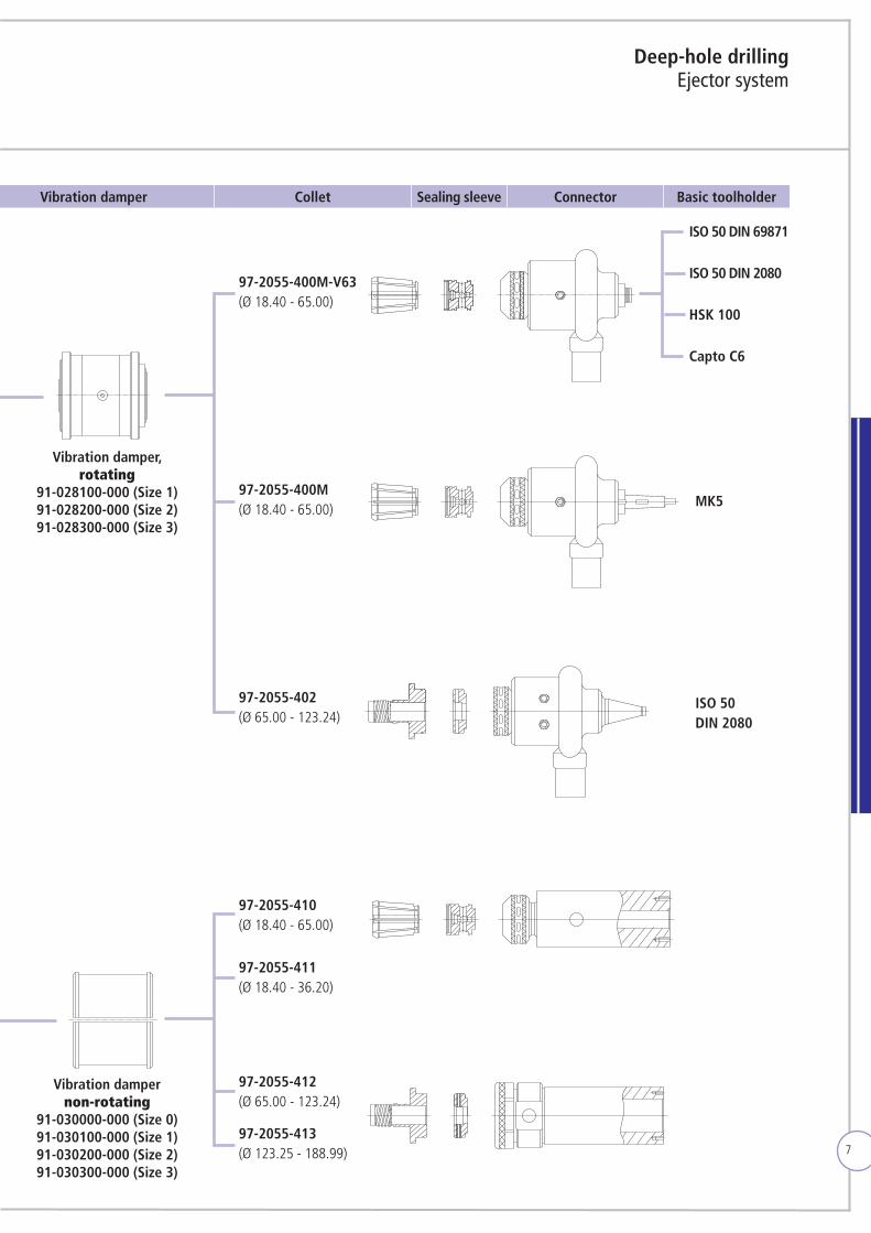
Deep-hole drilling Ejector system
97-2055-400M-V63(Ø 18.40 - 65.00)
97-2055-400M(Ø 18.40 - 65.00)
97-2055-402(Ø 65.00 - 123.24)
97-2055-410(Ø 18.40 - 65.00)
97-2055-411(Ø 18.40 - 36.20)
97-2055-412(Ø 65.00 - 123.24)
97-2055-413(Ø 123.25 - 188.99)
ISO 50 DIN 69871
ISO 50 DIN 2080
HSK 100
Capto C6
MK5
ISO 50DIN 2080
Drill head Drill tube, inner tube Vibration damper Collet Sealing sleeve Connector Basic toolholder
Vibration damper, rotating
91-028100-000 (Size 1) 91-028200-000 (Size 2) 91-028300-000 (Size 3)
Vibration damper non-rotating
91-030000-000 (Size 0) 91-030100-000 (Size 1) 91-030200-000 (Size 2) 91-030300-000 (Size 3)
8
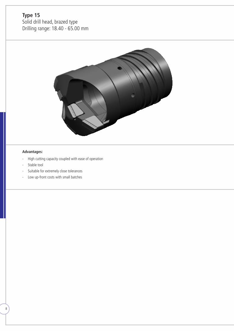
Type 15 Solid drill head, brazed typeDrilling range: 18.40 - 65.00 mm
Advantages: - High cutting capacity coupled with ease of operation
- Stable tool
- Suitable for extremely close tolerances
- Low up-front costs with small batches
9
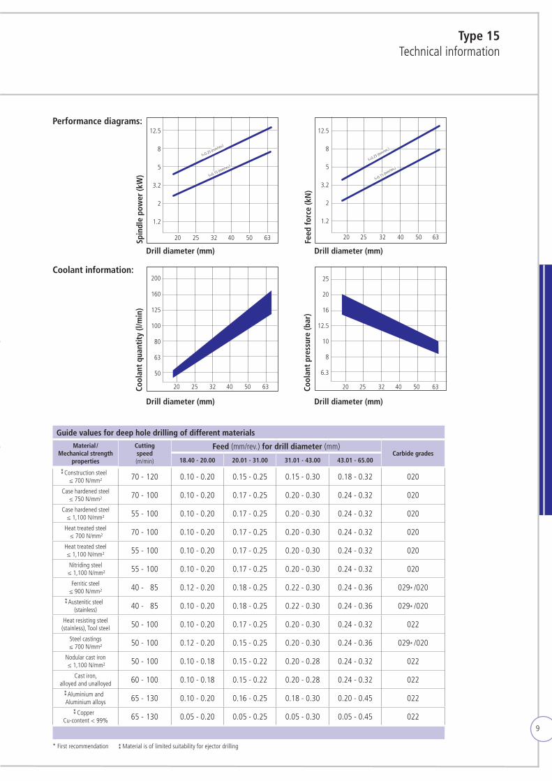
Type 15Technical information
Guide values for deep hole drilling of different materialsMaterial /
Mechanical strength properties
Cutting speed (m/min)
Feed (mm/rev.) for drill diameter (mm)Carbide grades
18.40 - 20.00 20.01 - 31.00 31.01 - 43.00 43.01 - 65.00
Construction steel≤ 700 N/mm² 170 - 120 0.10 - 0.20 0.15 - 0.25 0.15 - 0.30 0.18 - 0.32 020
Case hardened steel≤ 750 N/mm² 170 - 100 0.10 - 0.20 0.17 - 0.25 0.20 - 0.30 0.24 - 0.32 020
Case hardened steel≤ 1,100 N/mm² 155 - 100 0.10 - 0.20 0.17 - 0.25 0.20 - 0.30 0.24 - 0.32 020
Heat treated steel ≤ 700 N/mm² 170 - 100 0.10 - 0.20 0.17 - 0.25 0.20 - 0.30 0.24 - 0.32 020
Heat treated steel ≤ 1,100 N/mm² 155 - 100 0.10 - 0.20 0.17 - 0.25 0.20 - 0.30 0.24 - 0.32 020
Nitriding steel ≤ 1,100 N/mm² 155 - 100 0.10 - 0.20 0.17 - 0.25 0.20 - 0.30 0.24 - 0.32 020
Ferritic steel ≤ 900 N/mm² 140 - 85 0.12 - 0.20 0.18 - 0.25 0.22 - 0.30 0.24 - 0.36 029 /020
Austenitic steel (stainless) 140 - 85 0.10 - 0.20 0.18 - 0.25 0.22 - 0.30 0.24 - 0.36 029 /020
Heat resisting steel(stainless), Tool steel 150 - 100 0.10 - 0.20 0.17 - 0.25 0.20 - 0.30 0.24 - 0.32 022
Steel castings ≤ 700 N/mm² 150 - 100 0.12 - 0.20 0.15 - 0.25 0.20 - 0.30 0.24 - 0.36 029 /020
Nodular cast iron ≤ 1,100 N/mm² 150 - 100 0.10 - 0.18 0.15 - 0.22 0.20 - 0.28 0.24 - 0.32 022
Cast iron,alloyed and unalloyed 160 - 100 0.10 - 0.18 0.15 - 0.22 0.20 - 0.28 0.24 - 0.32 022
Aluminium andAluminium alloys 165 - 130 0.10 - 0.20 0.16 - 0.25 0.18 - 0.30 0.20 - 0.45 022
CopperCu-content < 99% 165 - 130 0.05 - 0.20 0.05 - 0.25 0.05 - 0.30 0.05 - 0.45 022
Performance diagrams:
Coolant information:
12.5
8
5
3.2
2
1.2
20 25 32 40 50 63
f=0.25 (mm/rev.)
f=0.15 (mm/rev.)
12.5
8
5
3.2
2
1.2
20 25 32 40 50 63
f=0.25 (mm/rev.)
f=0.15 (mm/rev.)
Spin
dle
pow
er (k
W)
Cool
ant
quan
tity
(l/m
in)
Feed
forc
e (k
N)
Cool
ant
pres
sure
(bar
)
Drill diameter (mm)
Drill diameter (mm)
Drill diameter (mm)
Drill diameter (mm)
200
160
125
100
80
63
50
20 25 32 40 50 63
25
20
16
12.5
10
8
6.3
20 25 32 40 50 63
* First recommendation Material is of limited suitability for ejector drilling

10
Advantages: - Very economical, with optimal cutting capacity
- Indexable inserts with various chip breakers available to suit processed material
- Tool adjustment range up to 1 mm using suitable replacement parts
Type 60 Solid drill head with indexable inserts and guide pads,diameter adjustment with stop plateDiameter range: 18.40 - 36.20 mm
11
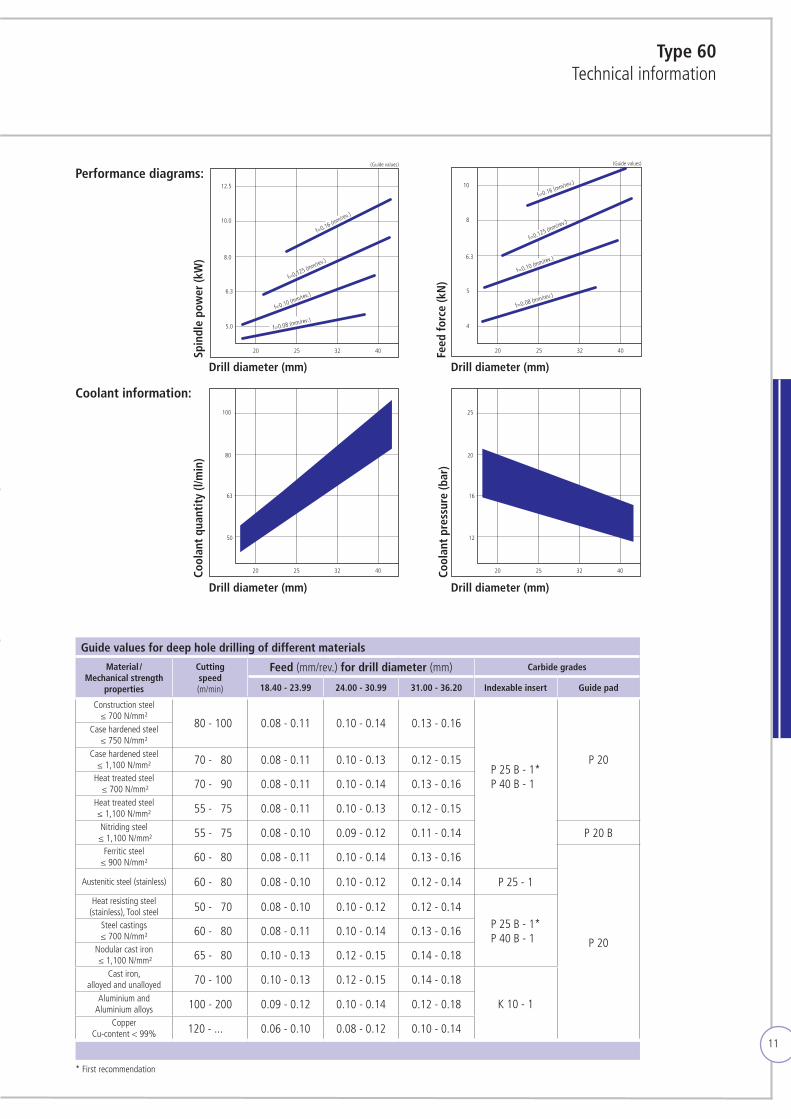
Type 60Technical information
Guide values for deep hole drilling of different materials
Material / Mechanical strength
properties
Cutting speed (m/min)
Feed (mm/rev.) for drill diameter (mm) Carbide grades
18.40 - 23.99 24.00 - 30.99 31.00 - 36.20 Indexable insert Guide pad
Construction steel≤ 700 N/mm²
180 - 100 0.08 - 0.11 0.10 - 0.14 0.13 - 0.16
P 25 B - 1* P 40 B - 1*
P 20
Case hardened steel≤ 750 N/mm²
Case hardened steel≤ 1,100 N/mm² 170 - 180 0.08 - 0.11 0.10 - 0.13 0.12 - 0.15
Heat treated steel ≤ 700 N/mm² 170 - 190 0.08 - 0.11 0.10 - 0.14 0.13 - 0.16
Heat treated steel ≤ 1,100 N/mm² 155 - 175 0.08 - 0.11 0.10 - 0.13 0.12 - 0.15
Nitriding steel ≤ 1,100 N/mm² 155 - 175 0.08 - 0.10 0.09 - 0.12 0.11 - 0.14 P 20 B
Ferritic steel ≤ 900 N/mm² 160 - 180 0.08 - 0.11 0.10 - 0.14 0.13 - 0.16
P 20
Austenitic steel (stainless) 160 - 180 0.08 - 0.10 0.10 - 0.12 0.12 - 0.14 P 25 - 1
Heat resisting steel(stainless), Tool steel 150 - 170 0.08 - 0.10 0.10 - 0.12 0.12 - 0.14
P 25 B - 1* P 40 B - 1*
Steel castings ≤ 700 N/mm² 160 - 180 0.08 - 0.11 0.10 - 0.14 0.13 - 0.16
Nodular cast iron ≤ 1,100 N/mm² 165 - 180 0.10 - 0.13 0.12 - 0.15 0.14 - 0.18
Cast iron,alloyed and unalloyed 170 - 100 0.10 - 0.13 0.12 - 0.15 0.14 - 0.18
K 10 - 1Aluminium andAluminium alloys 100 - 200 0.09 - 0.12 0.10 - 0.14 0.12 - 0.18
CopperCu-content < 99% 120 - ... 0.06 - 0.10 0.08 - 0.12 0.10 - 0.14
20 25 32 40
12
16
20
25
20 25 32 40
50
63
80
100
20 25 32 40
4
5
6.3
8
10
(Guide values)
f=0.08 (mm/rev.)
f=0.10 (mm/rev.)
f=0.125 (mm/rev.)
f=0.16 (mm/rev.)
20 25 32 40
5.0
6.3
8.0
10.0
12.5
(Guide values)
f=0.08 (mm/rev.)
f=0.10 (mm/rev.)
f=0.125 (mm/rev.)
f=0.16 (mm/rev.)
Performance diagrams:
Coolant information:
Spin
dle
pow
er (k
W)
Cool
ant
quan
tity
(l/m
in)
Feed
forc
e (k
N)
Drill diameter (mm)
Drill diameter (mm)
Drill diameter (mm)
Drill diameter (mm)
Cool
ant
pres
sure
(bar
)
20 25 32 40
12
16
20
25
20 25 32 40
50
63
80
100
20 25 32 40
4
5
6.3
8
10
(Guide values)
f=0.08 (mm/rev.)
f=0.10 (mm/rev.)
f=0.125 (mm/rev.)
f=0.16 (mm/rev.)
20 25 32 40
5.0
6.3
8.0
10.0
12.5
(Guide values)
f=0.08 (mm/rev.)
f=0.10 (mm/rev.)
f=0.125 (mm/rev.)
f=0.16 (mm/rev.)
20 25 32 40
12
16
20
25
20 25 32 40
50
63
80
100
20 25 32 40
4
5
6,3
8
10
(Richtwerte)
f=0,08 (mm/U)
f=0,10 (mm/U)
f=0,125 (mm/U)
f=0,16 (mm/U)
20 25 32 40
5,0
6,3
8,0
10,0
12,5
(Richtwerte)
f=0,08 (mm/U)
f=0,10 (mm/U)
f=0,125 (mm/U)
f=0,16 (mm/U)
20 25 32 40
12
16
20
25
20 25 32 40
50
63
80
100
20 25 32 40
4
5
6,3
8
10
(Richtwerte)
f=0,08 (mm/U)
f=0,10 (mm/U)
f=0,125 (mm/U)
f=0,16 (mm/U)
20 25 32 40
5,0
6,3
8,0
10,0
12,5
(Richtwerte)
f=0,08 (mm/U)
f=0,10 (mm/U)
f=0,125 (mm/U)
f=0,16 (mm/U)
* First recommendation
12
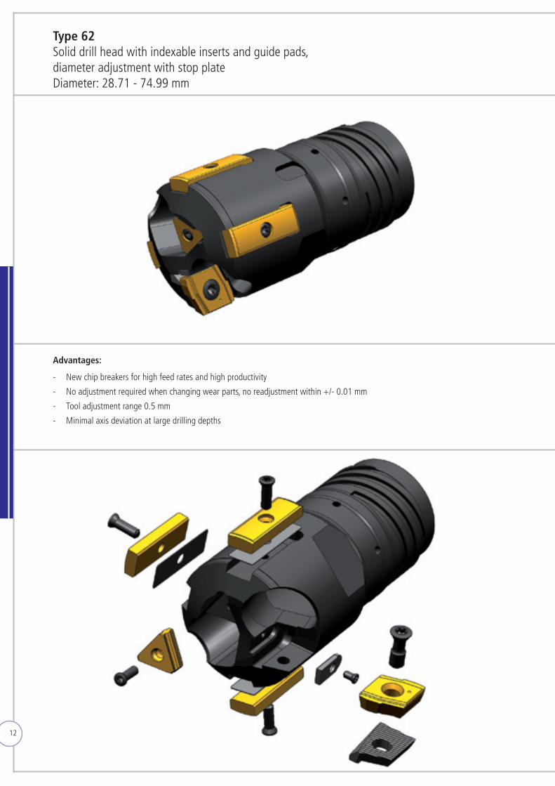
Type 62 Solid drill head with indexable inserts and guide pads,diameter adjustment with stop plateDiameter: 28.71 - 74.99 mm
Advantages: - New chip breakers for high feed rates and high productivity
- No adjustment required when changing wear parts, no readjustment within +/- 0.01 mm
- Tool adjustment range 0.5 mm
- Minimal axis deviation at large drilling depths
13
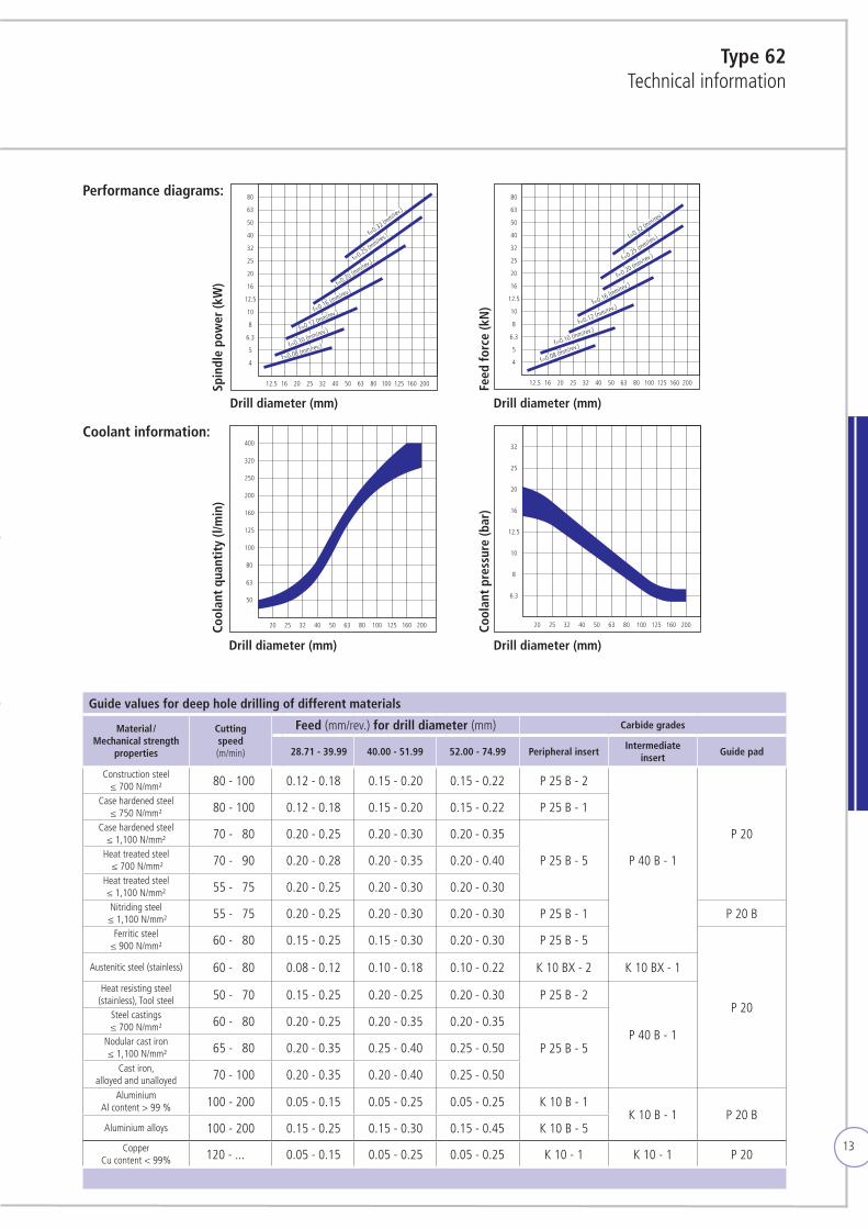
Type 62Technical information
12.5 16 20 25 32 40 50 63 80 100 125 160 200
5
6.3
8
10
12.5
16
20
25
32
40
50
63
80
4
f=0.32 (mm/rev
.)
f=0.25 (mm/rev
.)
f=0.20 (mm/rev
.)
f=0.16 (mm/rev.)
f=0.12 (mm/rev.)
f=0.10 (mm/rev.)
f=0.08 (mm/rev.)
12.5 16 20 25 32 40 50 63 80 100 125 160 200
5
6.3
8
10
12.5
16
20
25
32
40
50
63
80
4
f=0.32 (mm/rev
.)
f=0.25 (mm/rev
.)
f=0.20 (mm/rev.)
f=0.16 (mm/rev.)
f=0.12 (mm/rev.)
f=0.10 (mm/rev.)
f=0.08 (mm/rev.)
50
20 25 32 40 50 63 80 100 125 160 200
63
80
100
125
160
200
250
320
400
6.3
20 25 32 40 50 63 80 100 125 160 200
8
10
12.5
16
20
25
32
12.5 16 20 25 32 40 50 63 80 100 125 160 200
5
6.3
8
10
12.5
16
20
25
32
40
50
63
80
4
f=0.32 (mm/rev
.)
f=0.25 (mm/rev
.)
f=0.20 (mm/rev
.)
f=0.16 (mm/rev.)
f=0.12 (mm/rev.)
f=0.10 (mm/rev.)
f=0.08 (mm/rev.)
12.5 16 20 25 32 40 50 63 80 100 125 160 200
5
6.3
8
10
12.5
16
20
25
32
40
50
63
80
4
f=0.32 (mm/rev
.)
f=0.25 (mm/rev
.)
f=0.20 (mm/rev.)
f=0.16 (mm/rev.)
f=0.12 (mm/rev.)
f=0.10 (mm/rev.)
f=0.08 (mm/rev.)
50
20 25 32 40 50 63 80 100 125 160 200
63
80
100
125
160
200
250
320
400
6.3
20 25 32 40 50 63 80 100 125 160 200
8
10
12.5
16
20
25
32
12,5 16 20 25 32 40 50 63 80 100 125 160 200
5
6,3
8
10
12,5
16
20
25
32
40
50
63
80
4
f=0,32 (mm/U)
f=0,25 (mm/U)
f=0,20 (mm/U)
f=0,16 (mm/U)
f=0,12 (mm/U)
f=0,10 (mm/U)
f=0,08 (mm/U)
Antri
ebsle
istun
g Sp
inde
lmot
or (k
W)
12,5 16 20 25 32 40 50 63 80 100 125 160 200
5
6,3
8
10
12,5
16
20
25
32
40
50
63
80
4
f=0,32 (mm/U)
f=0,25 (mm/U)
f=0,20 (mm/U)
f=0,16 (mm/U)
f=0,12 (mm/U)
f=0,10 (mm/U)
f=0,08 (mm/U)
Vors
chub
kraf
t (kN
)
50
Kühl
schm
iers
toffm
enge
(l/m
in)
20 25 32 40 50 63 80 100 125 160 200
63
80
100
125
160
200
250
320
400
6,3
Kühl
schm
iers
toffd
ruck
(bar
)
20 25 32 40 50 63 80 100 125 160 200
8
10
12,5
16
20
25
32
12.5 16 20 25 32 40 50 63 80 100 125 160 200
5
6.3
8
10
12.5
16
20
25
32
40
50
63
80
4
f=0.32 (mm/rev
.)
f=0.25 (mm/rev
.)
f=0.20 (mm/rev
.)
f=0.16 (mm/rev.)
f=0.12 (mm/rev.)
f=0.10 (mm/rev.)
f=0.08 (mm/rev.)
12.5 16 20 25 32 40 50 63 80 100 125 160 200
5
6.3
8
10
12.5
16
20
25
32
40
50
63
80
4
f=0.32 (mm/rev
.)
f=0.25 (mm/rev
.)
f=0.20 (mm/rev.)
f=0.16 (mm/rev.)
f=0.12 (mm/rev.)
f=0.10 (mm/rev.)
f=0.08 (mm/rev.)
50
20 25 32 40 50 63 80 100 125 160 200
63
80
100
125
160
200
250
320
400
6.3
20 25 32 40 50 63 80 100 125 160 200
8
10
12.5
16
20
25
32
Performance diagrams:
Coolant information:
Guide values for deep hole drilling of different materials
Material / Mechanical strength
properties
Cutting speed (m/min)
Feed (mm/rev.) for drill diameter (mm) Carbide grades
28.71 - 39.99 40.00 - 51.99 52.00 - 74.99 Peripheral insertIntermediate
insertGuide pad
Construction steel≤ 700 N/mm² 180 - 100 0.12 - 0.18 0.15 - 0.20 0.15 - 0.22 P 25 B - 2
P 40 B - 1
P 20
Case hardened steel≤ 750 N/mm² 180 - 100 0.12 - 0.18 0.15 - 0.20 0.15 - 0.22 P 25 B - 1
Case hardened steel≤ 1,100 N/mm² 170 - 180 0.20 - 0.25 0.20 - 0.30 0.20 - 0.35
P 25 B - 5Heat treated steel ≤ 700 N/mm² 170 - 190 0.20 - 0.28 0.20 - 0.35 0.20 - 0.40
Heat treated steel ≤ 1,100 N/mm² 155 - 175 0.20 - 0.25 0.20 - 0.30 0.20 - 0.30Nitriding steel
≤ 1,100 N/mm² 155 - 175 0.20 - 0.25 0.20 - 0.30 0.20 - 0.30 P 25 B - 1 P 20 BFerritic steel
≤ 900 N/mm² 160 - 180 0.15 - 0.25 0.15 - 0.30 0.20 - 0.30 P 25 B - 5
P 20
Austenitic steel (stainless) 160 - 180 0.08 - 0.12 0.10 - 0.18 0.10 - 0.22 K 10 BX - 2 K 10 BX - 1
Heat resisting steel(stainless), Tool steel 150 - 170 0.15 - 0.25 0.20 - 0.25 0.20 - 0.30 P 25 B - 2
P 40 B - 1
Steel castings ≤ 700 N/mm² 160 - 180 0.20 - 0.25 0.20 - 0.35 0.20 - 0.35
P 25 B - 5Nodular cast iron ≤ 1,100 N/mm² 165 - 180 0.20 - 0.35 0.25 - 0.40 0.25 - 0.50
Cast iron,alloyed and unalloyed 170 - 100 0.20 - 0.35 0.20 - 0.40 0.25 - 0.50
AluminiumAl content > 99 % 100 - 200 0.05 - 0.15 0.05 - 0.25 0.05 - 0.25 K 10 B - 1
K 10 B - 1 P 20 BAluminium alloys 100 - 200 0.15 - 0.25 0.15 - 0.30 0.15 - 0.45 K 10 B - 5
CopperCu content < 99% 120 - ... 0.05 - 0.15 0.05 - 0.25 0.05 - 0.25 K 10 - 1 K 10 - 1 P 20
Spin
dle
pow
er (k
W)
Cool
ant
quan
tity
(l/m
in)
Feed
forc
e (k
N)
Cool
ant
pres
sure
(bar
)
Drill diameter (mm)
Drill diameter (mm)
Drill diameter (mm)
Drill diameter (mm)
14
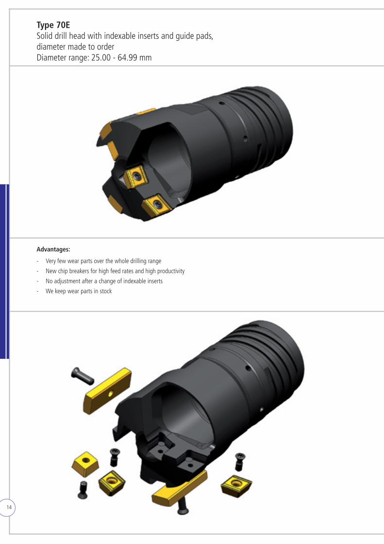
Type 70E Solid drill head with indexable inserts and guide pads,diameter made to orderDiameter range: 25.00 - 64.99 mm
Advantages: - Very few wear parts over the whole drilling range
- New chip breakers for high feed rates and high productivity
- No adjustment after a change of indexable inserts
- Wekeepwearpartsinstock
15
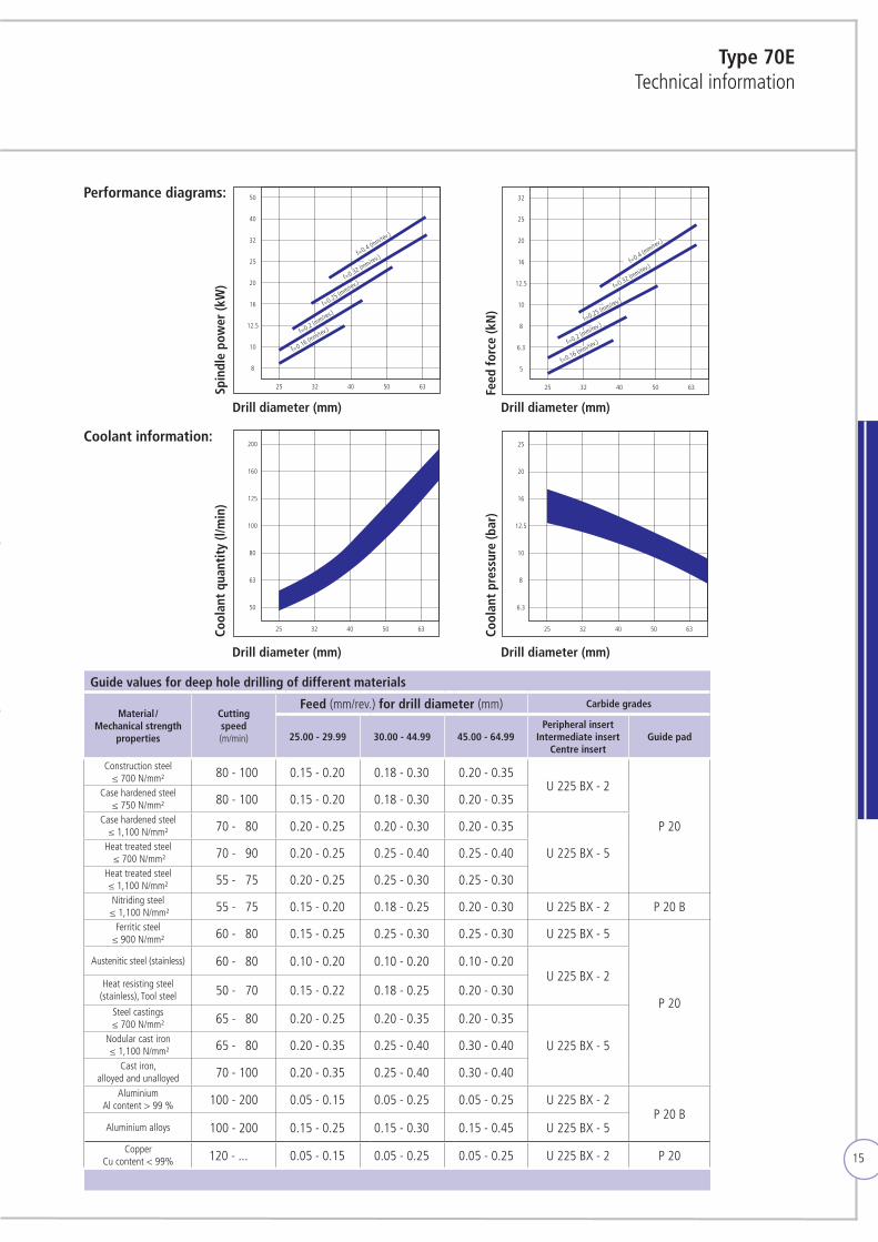
Type 70ETechnical information
25
5
32 40 50 63
6.3
8
10
12.5
16
20
25
32
f=0.16 (mm/rev.)f=0.2 (mm/rev.)f=0.25 (mm/rev.)
f=0.32 (mm/rev.)
f=0.4 (mm/rev
.)
25
8
32 40 50 63
10
12.5
16
20
25
32
40
50
f=0.16 (mm/rev.)f=0.2 (m
m/rev.)f=0.25 (m
m/rev.)f=0.32 (m
m/rev.)f=0.4 (m
m/rev.)
25
50
32 40 50 63 25 32 40 50 63
63
80
100
125
160
200
6.3
8
10
12.5
16
20
25
25
5
32 40 50 63
6,3
8
10
12,5
16
20
25
32
f=0,16 (mm/U)f=0,2 (mm/U)f=0,25 (mm/U)
f=0,32 (mm/U)
f=0,4 (mm/U)
25
8
Antri
ebsle
istun
g (k
W)
Vors
chub
kraf
t (kN
)
Kühl
schm
iers
toffm
enge
(l/m
in)
Kühl
schm
iers
toffd
ruck
(bar
)
32 40 50 63
10
12,5
16
20
25
32
40
50
f=0,16 (mm/U)f=0,2 (m
m/U)
f=0,25 (mm/U)f=0,32 (m
m/U)f=0,4 (m
m/U)
25
50
32 40 50 63 25 32 40 50 63
63
80
100
125
160
200
6,3
8
10
12,5
16
20
25
25
5
32 40 50 63
6.3
8
10
12.5
16
20
25
32
f=0.16 (mm/rev.)f=0.2 (mm/rev.)f=0.25 (mm/rev.)
f=0.32 (mm/rev.)
f=0.4 (mm/rev
.)
25
8
32 40 50 63
10
12.5
16
20
25
32
40
50
f=0.16 (mm/rev.)f=0.2 (m
m/rev.)f=0.25 (m
m/rev.)f=0.32 (m
m/rev.)f=0.4 (m
m/rev.)
25
50
32 40 50 63 25 32 40 50 63
63
80
100
125
160
200
6.3
8
10
12.5
16
20
25
Guide values for deep hole drilling of different materials
Material / Mechanical strength
properties
Cutting speed (m/min)
Feed (mm/rev.) for drill diameter (mm) Carbide grades
25.00 - 29.99 30.00 - 44.99 45.00 - 64.99Peripheral insert
Intermediate insertCentre insert
Guide pad
Construction steel≤ 700 N/mm² 180 - 100 0.15 - 0.20 0.18 - 0.30 0.20 - 0.35
U 225 BX - 2
P 20
Case hardened steel≤ 750 N/mm² 180 - 100 0.15 - 0.20 0.18 - 0.30 0.20 - 0.35
Case hardened steel≤ 1,100 N/mm² 170 - 180 0.20 - 0.25 0.20 - 0.30 0.20 - 0.35
U 225 BX - 5Heat treated steel ≤ 700 N/mm² 170 - 190 0.20 - 0.25 0.25 - 0.40 0.25 - 0.40
Heat treated steel ≤ 1,100 N/mm² 155 - 175 0.20 - 0.25 0.25 - 0.30 0.25 - 0.30Nitriding steel
≤ 1,100 N/mm² 155 - 175 0.15 - 0.20 0.18 - 0.25 0.20 - 0.30 U 225 BX - 2 P 20 BFerritic steel
≤ 900 N/mm² 160 - 180 0.15 - 0.25 0.25 - 0.30 0.25 - 0.30 U 225 BX - 5
P 20
Austenitic steel (stainless) 160 - 180 0.10 - 0.20 0.10 - 0.20 0.10 - 0.20U 225 BX - 2
Heat resisting steel(stainless), Tool steel 150 - 170 0.15 - 0.22 0.18 - 0.25 0.20 - 0.30
Steel castings ≤ 700 N/mm² 165 - 180 0.20 - 0.25 0.20 - 0.35 0.20 - 0.35
U 225 BX - 5Nodular cast iron ≤ 1,100 N/mm² 165 - 180 0.20 - 0.35 0.25 - 0.40 0.30 - 0.40
Cast iron,alloyed and unalloyed 170 - 100 0.20 - 0.35 0.25 - 0.40 0.30 - 0.40
AluminiumAl content > 99 % 100 - 200 0.05 - 0.15 0.05 - 0.25 0.05 - 0.25 U 225 BX - 2
P 20 BAluminium alloys 100 - 200 0.15 - 0.25 0.15 - 0.30 0.15 - 0.45 U 225 BX - 5
CopperCu content < 99% 120 - ... 0.05 - 0.15 0.05 - 0.25 0.05 - 0.25 U 225 BX - 2 P 20
Performance diagrams:
Coolant information:
Spin
dle
pow
er (k
W)
Cool
ant
quan
tity
(l/m
in)
Feed
forc
e (k
N)
Cool
ant
pres
sure
(bar
)
Drill diameter (mm)
Drill diameter (mm)
Drill diameter (mm)
Drill diameter (mm)
16
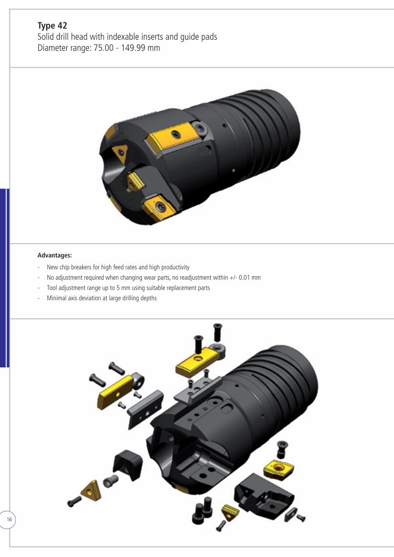
Advantages: - New chip breakers for high feed rates and high productivity
- No adjustment required when changing wear parts, no readjustment within +/- 0.01 mm
- Tool adjustment range up to 5 mm using suitable replacement parts
- Minimal axis deviation at large drilling depths
Type 42 Solid drill head with indexable inserts and guide padsDiameter range: 75.00 - 149.99 mm
17
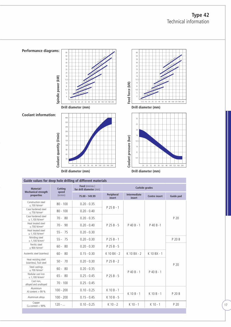
Type 42Technical information
Guide values for deep hole drilling of different materials
Material / Mechanical strength
properties
Cutting speed (m/min)
Feed (mm/rev.) for drill diameter (mm)
Carbide grades
75.00 - 149.99Peripheral
insertIntermediate
insertCentre insert Guide pad
Construction steel≤ 700 N/mm² 180 - 100 0.20 - 0.35
P 25 B - 1
P 40 B - 1 P 40 B -1
P 20
Case hardened steel≤ 750 N/mm² 180 - 100 0.20 - 0.40
Case hardened steel≤ 1,100 N/mm² 170 - 180 0.20 - 0.35
P 25 B - 5Heat treated steel ≤ 700 N/mm² 170 - 190 0.20 - 0.40
Heat treated steel ≤ 1,100 N/mm² 155 - 175 0.20 - 0.30Nitriding steel
≤ 1,100 N/mm² 155 - 175 0.20 - 0.30 P 25 B - 1 P 20 BFerritic steel
≤ 900 N/mm² 160 - 180 0.20 - 0.30 P 25 B - 5
P 20
Austenitic steel (stainless) 160 - 180 0.15 - 0.30 K 10 BX - 2 K 10 BX - 2 K 10 BX - 1
Heat resisting steel(stainless), Tool steel 150 - 170 0.20 - 0.30 P 25 B - 2
P 40 B - 1 P 40 B - 1
Steel castings ≤ 700 N/mm² 160 - 180 0.20 - 0.35
P 25 B - 5Nodular cast iron ≤ 1,100 N/mm² 165 - 180 0.25 - 0.45
Cast iron,alloyed and unalloyed 170 - 100 0.25 - 0.45
AluminiumAl content > 99 % 100 - 200 0.10 - 0.25 K 10 B - 1
K 10 B - 1 K 10 B - 1 P 20 BAluminium alloys 100 - 200 0.15 - 0.45 K 10 B - 5
CopperCu content < 99% 120 - ... 0.10 - 0.25 K 10 - 2 K 10 - 1 K 10 - 1 P 20
12.5 16 20 25 32 40 50 63 80 100 125 160 200
5
6.3
8
10
12.5
16
20
25
32
40
50
63
80
4
f=0.32 (mm/rev
.)
f=0.25 (mm/rev
.)
f=0.20 (mm/rev
.)
f=0.16 (mm/rev.)
f=0.12 (mm/rev.)
f=0.10 (mm/rev.)
f=0.08 (mm/rev.)
12.5 16 20 25 32 40 50 63 80 100 125 160 200
5
6.3
8
10
12.5
16
20
25
32
40
50
63
80
4
f=0.32 (mm/rev
.)
f=0.25 (mm/rev
.)
f=0.20 (mm/rev.)
f=0.16 (mm/rev.)
f=0.12 (mm/rev.)
f=0.10 (mm/rev.)
f=0.08 (mm/rev.)
50
20 25 32 40 50 63 80 100 125 160 200
63
80
100
125
160
200
250
320
400
6.3
20 25 32 40 50 63 80 100 125 160 200
8
10
12.5
16
20
25
32
12.5 16 20 25 32 40 50 63 80 100 125 160 200
5
6.3
8
10
12.5
16
20
25
32
40
50
63
80
4
f=0.32 (mm/rev
.)
f=0.25 (mm/rev
.)
f=0.20 (mm/rev
.)
f=0.16 (mm/rev.)
f=0.12 (mm/rev.)
f=0.10 (mm/rev.)
f=0.08 (mm/rev.)
12.5 16 20 25 32 40 50 63 80 100 125 160 200
5
6.3
8
10
12.5
16
20
25
32
40
50
63
80
4
f=0.32 (mm/rev
.)
f=0.25 (mm/rev
.)
f=0.20 (mm/rev.)
f=0.16 (mm/rev.)
f=0.12 (mm/rev.)
f=0.10 (mm/rev.)
f=0.08 (mm/rev.)
50
20 25 32 40 50 63 80 100 125 160 200
63
80
100
125
160
200
250
320
400
6.3
20 25 32 40 50 63 80 100 125 160 200
8
10
12.5
16
20
25
32
12,5 16 20 25 32 40 50 63 80 100 125 160 200
5
6,3
8
10
12,5
16
20
25
32
40
50
63
80
4
f=0,32 (mm/U)
f=0,25 (mm/U)
f=0,20 (mm/U)
f=0,16 (mm/U)
f=0,12 (mm/U)
f=0,10 (mm/U)
f=0,08 (mm/U)
Antri
ebsle
istun
g Sp
inde
lmot
or (k
W)
12,5 16 20 25 32 40 50 63 80 100 125 160 200
5
6,3
8
10
12,5
16
20
25
32
40
50
63
80
4
f=0,32 (mm/U)
f=0,25 (mm/U)
f=0,20 (mm/U)
f=0,16 (mm/U)
f=0,12 (mm/U)
f=0,10 (mm/U)
f=0,08 (mm/U)
Vors
chub
kraf
t (kN
)
50
Kühl
schm
iers
toffm
enge
(l/m
in)
20 25 32 40 50 63 80 100 125 160 200
63
80
100
125
160
200
250
320
400
6,3
Kühl
schm
iers
toffd
ruck
(bar
)
20 25 32 40 50 63 80 100 125 160 200
8
10
12,5
16
20
25
32
12.5 16 20 25 32 40 50 63 80 100 125 160 200
5
6.3
8
10
12.5
16
20
25
32
40
50
63
80
4
f=0.32 (mm/rev
.)
f=0.25 (mm/rev
.)
f=0.20 (mm/rev
.)
f=0.16 (mm/rev.)
f=0.12 (mm/rev.)
f=0.10 (mm/rev.)
f=0.08 (mm/rev.)
12.5 16 20 25 32 40 50 63 80 100 125 160 200
5
6.3
8
10
12.5
16
20
25
32
40
50
63
80
4
f=0.32 (mm/rev
.)
f=0.25 (mm/rev
.)
f=0.20 (mm/rev.)
f=0.16 (mm/rev.)
f=0.12 (mm/rev.)
f=0.10 (mm/rev.)
f=0.08 (mm/rev.)
50
20 25 32 40 50 63 80 100 125 160 200
63
80
100
125
160
200
250
320
400
6.3
20 25 32 40 50 63 80 100 125 160 200
8
10
12.5
16
20
25
32
Performance diagrams:
Coolant information:
Spin
dle
pow
er (k
W)
Cool
ant
quan
tity
(l/m
in)
Feed
forc
e (k
N)
Cool
ant
pres
sure
(bar
)
Drill diameter (mm)
Drill diameter (mm)
Drill diameter (mm)
Drill diameter (mm)
18
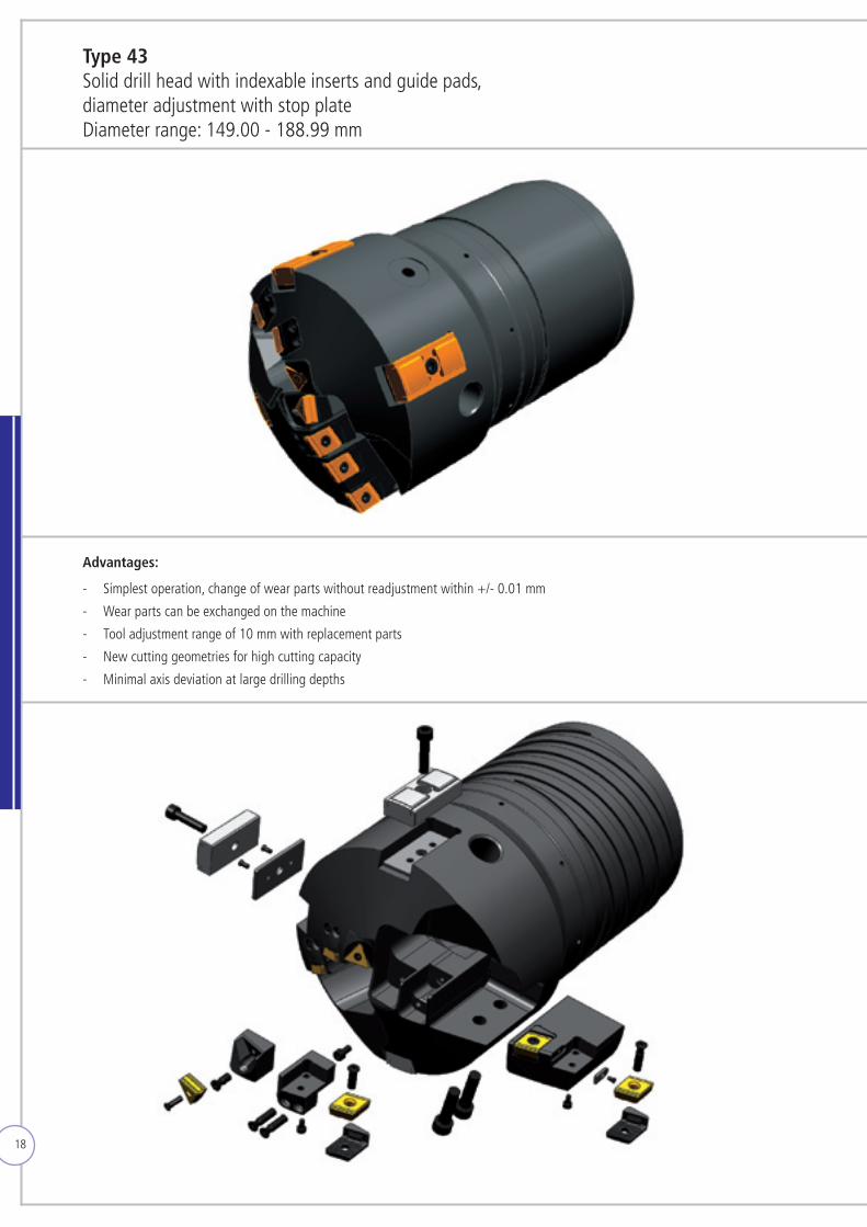
Advantages: - Simplest operation, change of wear parts without readjustment within +/- 0.01 mm
- Wearpartscanbeexchangedonthemachine
- Tool adjustment range of 10 mm with replacement parts
- New cutting geometries for high cutting capacity
- Minimal axis deviation at large drilling depths
Type 43Solid drill head with indexable inserts and guide pads,diameter adjustment with stop plateDiameter range: 149.00 - 188.99 mm
19
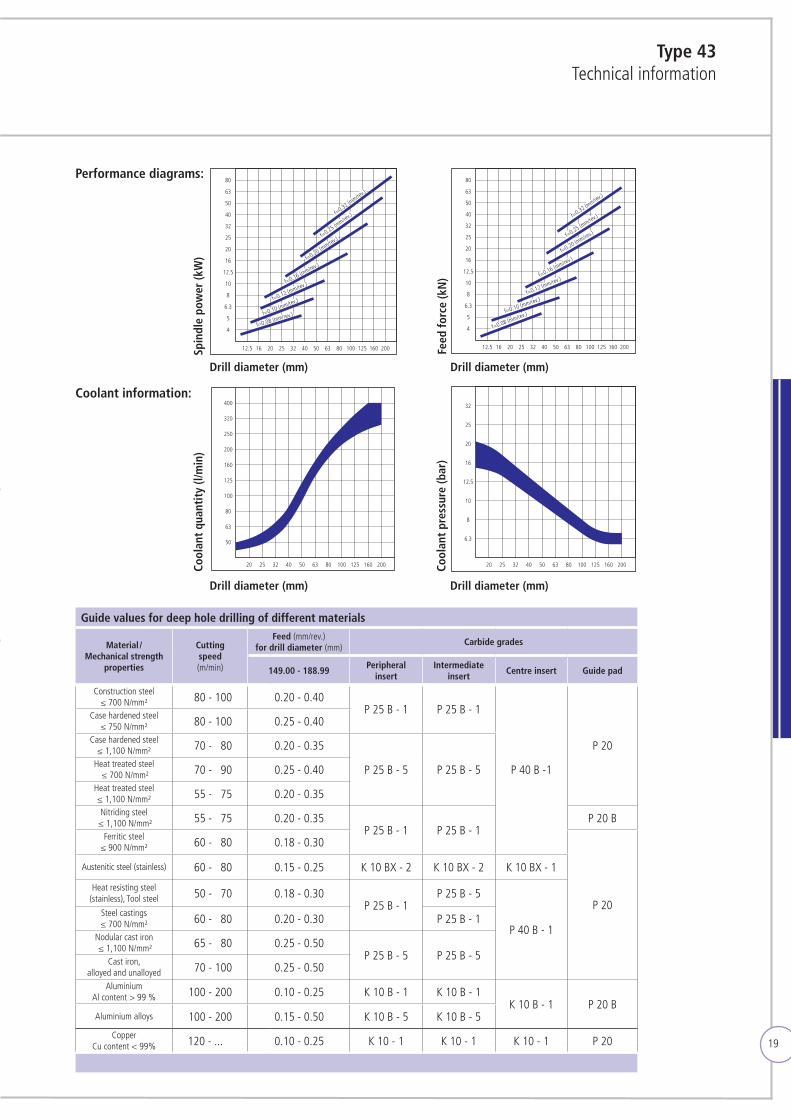
Type 43Technical information
12.5 16 20 25 32 40 50 63 80 100 125 160 200
5
6.3
8
10
12.5
16
20
25
32
40
50
63
80
4
f=0.32 (mm/rev
.)
f=0.25 (mm/rev
.)
f=0.20 (mm/rev
.)
f=0.16 (mm/rev.)
f=0.12 (mm/rev.)
f=0.10 (mm/rev.)
f=0.08 (mm/rev.)
12.5 16 20 25 32 40 50 63 80 100 125 160 200
5
6.3
8
10
12.5
16
20
25
32
40
50
63
80
4
f=0.32 (mm/rev
.)
f=0.25 (mm/rev
.)
f=0.20 (mm/rev.)
f=0.16 (mm/rev.)
f=0.12 (mm/rev.)
f=0.10 (mm/rev.)
f=0.08 (mm/rev.)
50
20 25 32 40 50 63 80 100 125 160 200
63
80
100
125
160
200
250
320
400
6.3
20 25 32 40 50 63 80 100 125 160 200
8
10
12.5
16
20
25
32
12.5 16 20 25 32 40 50 63 80 100 125 160 200
5
6.3
8
10
12.5
16
20
25
32
40
50
63
80
4
f=0.32 (mm/rev
.)
f=0.25 (mm/rev
.)
f=0.20 (mm/rev
.)
f=0.16 (mm/rev.)
f=0.12 (mm/rev.)
f=0.10 (mm/rev.)
f=0.08 (mm/rev.)
12.5 16 20 25 32 40 50 63 80 100 125 160 200
5
6.3
8
10
12.5
16
20
25
32
40
50
63
80
4
f=0.32 (mm/rev
.)
f=0.25 (mm/rev
.)
f=0.20 (mm/rev.)
f=0.16 (mm/rev.)
f=0.12 (mm/rev.)
f=0.10 (mm/rev.)
f=0.08 (mm/rev.)
50
20 25 32 40 50 63 80 100 125 160 200
63
80
100
125
160
200
250
320
400
6.3
20 25 32 40 50 63 80 100 125 160 200
8
10
12.5
16
20
25
32
12,5 16 20 25 32 40 50 63 80 100 125 160 200
5
6,3
8
10
12,5
16
20
25
32
40
50
63
80
4
f=0,32 (mm/U)
f=0,25 (mm/U)
f=0,20 (mm/U)
f=0,16 (mm/U)
f=0,12 (mm/U)
f=0,10 (mm/U)
f=0,08 (mm/U)
Antri
ebsle
istun
g Sp
inde
lmot
or (k
W)
12,5 16 20 25 32 40 50 63 80 100 125 160 200
5
6,3
8
10
12,5
16
20
25
32
40
50
63
80
4
f=0,32 (mm/U)
f=0,25 (mm/U)
f=0,20 (mm/U)
f=0,16 (mm/U)
f=0,12 (mm/U)
f=0,10 (mm/U)
f=0,08 (mm/U)
Vors
chub
kraf
t (kN
)
50
Kühl
schm
iers
toffm
enge
(l/m
in)
20 25 32 40 50 63 80 100 125 160 200
63
80
100
125
160
200
250
320
400
6,3
Kühl
schm
iers
toffd
ruck
(bar
)
20 25 32 40 50 63 80 100 125 160 200
8
10
12,5
16
20
25
32
12.5 16 20 25 32 40 50 63 80 100 125 160 200
5
6.3
8
10
12.5
16
20
25
32
40
50
63
80
4
f=0.32 (mm/rev
.)
f=0.25 (mm/rev
.)
f=0.20 (mm/rev
.)
f=0.16 (mm/rev.)
f=0.12 (mm/rev.)
f=0.10 (mm/rev.)
f=0.08 (mm/rev.)
12.5 16 20 25 32 40 50 63 80 100 125 160 200
5
6.3
8
10
12.5
16
20
25
32
40
50
63
80
4
f=0.32 (mm/rev
.)
f=0.25 (mm/rev
.)
f=0.20 (mm/rev.)
f=0.16 (mm/rev.)
f=0.12 (mm/rev.)
f=0.10 (mm/rev.)
f=0.08 (mm/rev.)
50
20 25 32 40 50 63 80 100 125 160 200
63
80
100
125
160
200
250
320
400
6.3
20 25 32 40 50 63 80 100 125 160 200
8
10
12.5
16
20
25
32
Guide values for deep hole drilling of different materials
Material / Mechanical strength
properties
Cutting speed (m/min)
Feed (mm/rev.) for drill diameter (mm)
Carbide grades
149.00 - 188.99Peripheral
insertIntermediate
insertCentre insert Guide pad
Construction steel≤ 700 N/mm² 180 - 100 0.20 - 0.40
P 25 B - 1 P 25 B - 1
P 40 B -1
P 20
Case hardened steel≤ 750 N/mm² 180 - 100 0.25 - 0.40
Case hardened steel≤ 1,100 N/mm² 170 - 180 0.20 - 0.35
P 25 B - 5 P 25 B - 5Heat treated steel ≤ 700 N/mm² 170 - 190 0.25 - 0.40
Heat treated steel ≤ 1,100 N/mm² 155 - 175 0.20 - 0.35Nitriding steel
≤ 1,100 N/mm² 155 - 175 0.20 - 0.35P 25 B - 1 P 25 B - 1
P 20 BFerritic steel
≤ 900 N/mm² 160 - 180 0.18 - 0.30
P 20
Austenitic steel (stainless) 160 - 180 0.15 - 0.25 K 10 BX - 2 K 10 BX - 2 K 10 BX - 1
Heat resisting steel(stainless), Tool steel 150 - 170 0.18 - 0.30
P 25 B - 1P 25 B - 5
P 40 B - 1
Steel castings ≤ 700 N/mm² 160 - 180 0.20 - 0.30 P 25 B - 1
Nodular cast iron ≤ 1,100 N/mm² 165 - 180 0.25 - 0.50
P 25 B - 5 P 25 B - 5Cast iron,alloyed and unalloyed 170 - 100 0.25 - 0.50
AluminiumAl content > 99 % 100 - 200 0.10 - 0.25 K 10 B - 1 K 10 B - 1
K 10 B - 1 P 20 BAluminium alloys 100 - 200 0.15 - 0.50 K 10 B - 5 K 10 B - 5
CopperCu content < 99% 120 - ... 0.10 - 0.25 K 10 - 1 K 10 - 1 K 10 - 1 P 20
Performance diagrams:
Coolant information:
Spin
dle
pow
er (k
W)
Cool
ant
quan
tity
(l/m
in)
Feed
forc
e (k
N)
Cool
ant
pres
sure
(bar
)
Drill diameter (mm)
Drill diameter (mm)
Drill diameter (mm)
Drill diameter (mm)
20
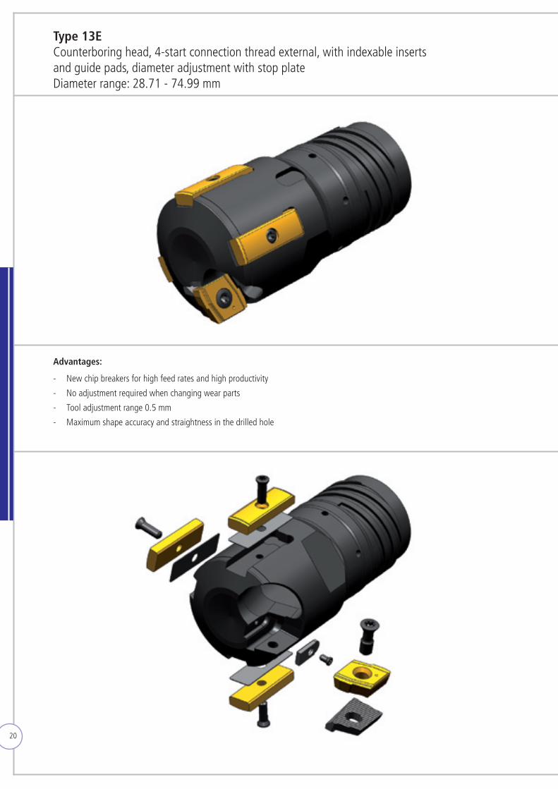
Type 13E Counterboring head, 4-start connection thread external, with indexable inserts and guide pads, diameter adjustment with stop plateDiameter range: 28.71 - 74.99 mm
Advantages: - New chip breakers for high feed rates and high productivity
- No adjustment required when changing wear parts
- Tool adjustment range 0.5 mm
- Maximum shape accuracy and straightness in the drilled hole
21
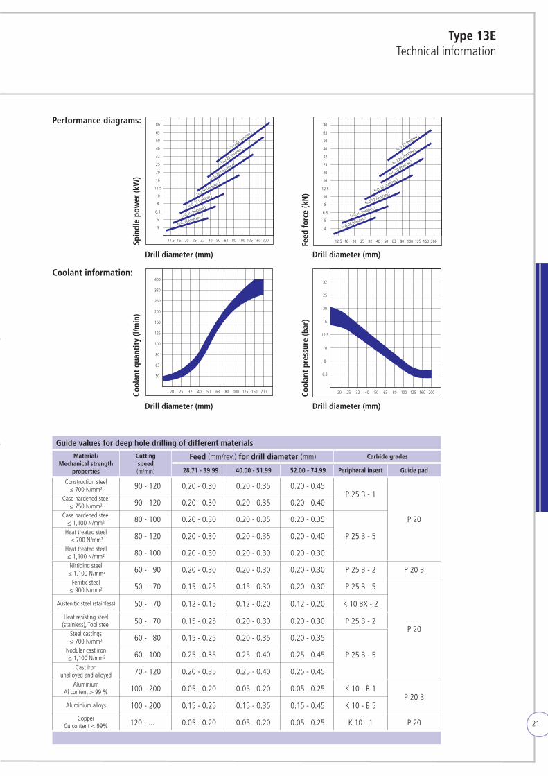
Type 13ETechnical information
Guide values for deep hole drilling of different materialsMaterial /
Mechanical strength properties
Cutting speed (m/min)
Feed (mm/rev.) for drill diameter (mm) Carbide grades
28.71 - 39.99 40.00 - 51.99 52.00 - 74.99 Peripheral insert Guide pad
Construction steel≤ 700 N/mm² 190 - 120 0.20 - 0.30 0.20 - 0.35 0.20 - 0.45
P 25 B - 1
P 20
Case hardened steel≤ 750 N/mm² 190 - 120 0.20 - 0.30 0.20 - 0.35 0.20 - 0.40
Case hardened steel≤ 1,100 N/mm² 180 - 100 0.20 - 0.30 0.20 - 0.35 0.20 - 0.35
P 25 B - 5Heat treated steel ≤ 700 N/mm² 180 - 120 0.20 - 0.30 0.20 - 0.35 0.20 - 0.40
Heat treated steel ≤ 1,100 N/mm² 180 - 100 0.20 - 0.30 0.20 - 0.30 0.20 - 0.30Nitriding steel
≤ 1,100 N/mm² 160 - 190 0.20 - 0.30 0.20 - 0.30 0.20 - 0.30 P 25 B - 2 P 20 BFerritic steel
≤ 900 N/mm² 150 - 170 0.15 - 0.25 0.15 - 0.30 0.20 - 0.30 P 25 B - 5
P 20
Austenitic steel (stainless) 150 - 170 0.12 - 0.15 0.12 - 0.20 0.12 - 0.20 K 10 BX - 2
Heat resisting steel(stainless), Tool steel 150 - 170 0.15 - 0.25 0.20 - 0.30 0.20 - 0.30 P 25 B - 2
Steel castings ≤ 700 N/mm² 160 - 180 0.15 - 0.25 0.20 - 0.35 0.20 - 0.35
P 25 B - 5Nodular cast iron ≤ 1,100 N/mm² 160 - 100 0.25 - 0.35 0.25 - 0.40 0.25 - 0.45
Cast ironunalloyed and alloyed 170 - 120 0.20 - 0.35 0.25 - 0.40 0.25 - 0.45
AluminiumAl content > 99 % 100 - 200 0.05 - 0.20 0.05 - 0.20 0.05 - 0.25 K 10 - B 1
P 20 BAluminium alloys 100 - 200 0.15 - 0.25 0.15 - 0.35 0.15 - 0.45 K 10 - B 5
CopperCu content < 99% 120 - ... 0.05 - 0.20 0.05 - 0.20 0.05 - 0.25 K 10 - 1 P 20
12.5 16 20 25 32 40 50 63 80 100 125 160 200
5
6.3
8
10
12.5
16
20
25
32
40
50
63
80
4
f=0.32 (mm/rev
.)
f=0.25 (mm/rev
.)
f=0.20 (mm/rev
.)
f=0.16 (mm/rev.)
f=0.12 (mm/rev.)
f=0.10 (mm/rev.)
f=0.08 (mm/rev.)
12.5 16 20 25 32 40 50 63 80 100 125 160 200
5
6.3
8
10
12.5
16
20
25
32
40
50
63
80
4
f=0.32 (mm/rev
.)
f=0.25 (mm/rev
.)
f=0.20 (mm/rev.)
f=0.16 (mm/rev.)
f=0.12 (mm/rev.)
f=0.10 (mm/rev.)
f=0.08 (mm/rev.)
50
20 25 32 40 50 63 80 100 125 160 200
63
80
100
125
160
200
250
320
400
6.3
20 25 32 40 50 63 80 100 125 160 200
8
10
12.5
16
20
25
32
12.5 16 20 25 32 40 50 63 80 100 125 160 200
5
6.3
8
10
12.5
16
20
25
32
40
50
63
80
4
f=0.32 (mm/rev
.)
f=0.25 (mm/rev
.)
f=0.20 (mm/rev
.)
f=0.16 (mm/rev.)
f=0.12 (mm/rev.)
f=0.10 (mm/rev.)
f=0.08 (mm/rev.)
12.5 16 20 25 32 40 50 63 80 100 125 160 200
5
6.3
8
10
12.5
16
20
25
32
40
50
63
80
4
f=0.32 (mm/rev
.)
f=0.25 (mm/rev
.)
f=0.20 (mm/rev.)
f=0.16 (mm/rev.)
f=0.12 (mm/rev.)
f=0.10 (mm/rev.)
f=0.08 (mm/rev.)
50
20 25 32 40 50 63 80 100 125 160 200
63
80
100
125
160
200
250
320
400
6.3
20 25 32 40 50 63 80 100 125 160 200
8
10
12.5
16
20
25
32
12,5 16 20 25 32 40 50 63 80 100 125 160 200
5
6,3
8
10
12,5
16
20
25
32
40
50
63
80
4
f=0,32 (mm/U)
f=0,25 (mm/U)
f=0,20 (mm/U)
f=0,16 (mm/U)
f=0,12 (mm/U)
f=0,10 (mm/U)
f=0,08 (mm/U)
Antri
ebsle
istun
g Sp
inde
lmot
or (k
W)
12,5 16 20 25 32 40 50 63 80 100 125 160 200
5
6,3
8
10
12,5
16
20
25
32
40
50
63
80
4
f=0,32 (mm/U)
f=0,25 (mm/U)
f=0,20 (mm/U)
f=0,16 (mm/U)
f=0,12 (mm/U)
f=0,10 (mm/U)
f=0,08 (mm/U)
Vors
chub
kraf
t (kN
)
50
Kühl
schm
iers
toffm
enge
(l/m
in)
20 25 32 40 50 63 80 100 125 160 200
63
80
100
125
160
200
250
320
400
6,3
Kühl
schm
iers
toffd
ruck
(bar
)
20 25 32 40 50 63 80 100 125 160 200
8
10
12,5
16
20
25
32
12.5 16 20 25 32 40 50 63 80 100 125 160 200
5
6.3
8
10
12.5
16
20
25
32
40
50
63
80
4
f=0.32 (mm/rev
.)
f=0.25 (mm/rev
.)
f=0.20 (mm/rev
.)
f=0.16 (mm/rev.)
f=0.12 (mm/rev.)
f=0.10 (mm/rev.)
f=0.08 (mm/rev.)
12.5 16 20 25 32 40 50 63 80 100 125 160 200
5
6.3
8
10
12.5
16
20
25
32
40
50
63
80
4
f=0.32 (mm/rev
.)
f=0.25 (mm/rev
.)
f=0.20 (mm/rev.)
f=0.16 (mm/rev.)
f=0.12 (mm/rev.)
f=0.10 (mm/rev.)
f=0.08 (mm/rev.)
50
20 25 32 40 50 63 80 100 125 160 200
63
80
100
125
160
200
250
320
400
6.3
20 25 32 40 50 63 80 100 125 160 200
8
10
12.5
16
20
25
32
Performance diagrams:
Coolant information:
Spin
dle
pow
er (k
W)
Cool
ant
quan
tity
(l/m
in)
Feed
forc
e (k
N)
Cool
ant
pres
sure
(bar
)
Drill diameter (mm)
Drill diameter (mm)
Drill diameter (mm)
Drill diameter (mm)
22
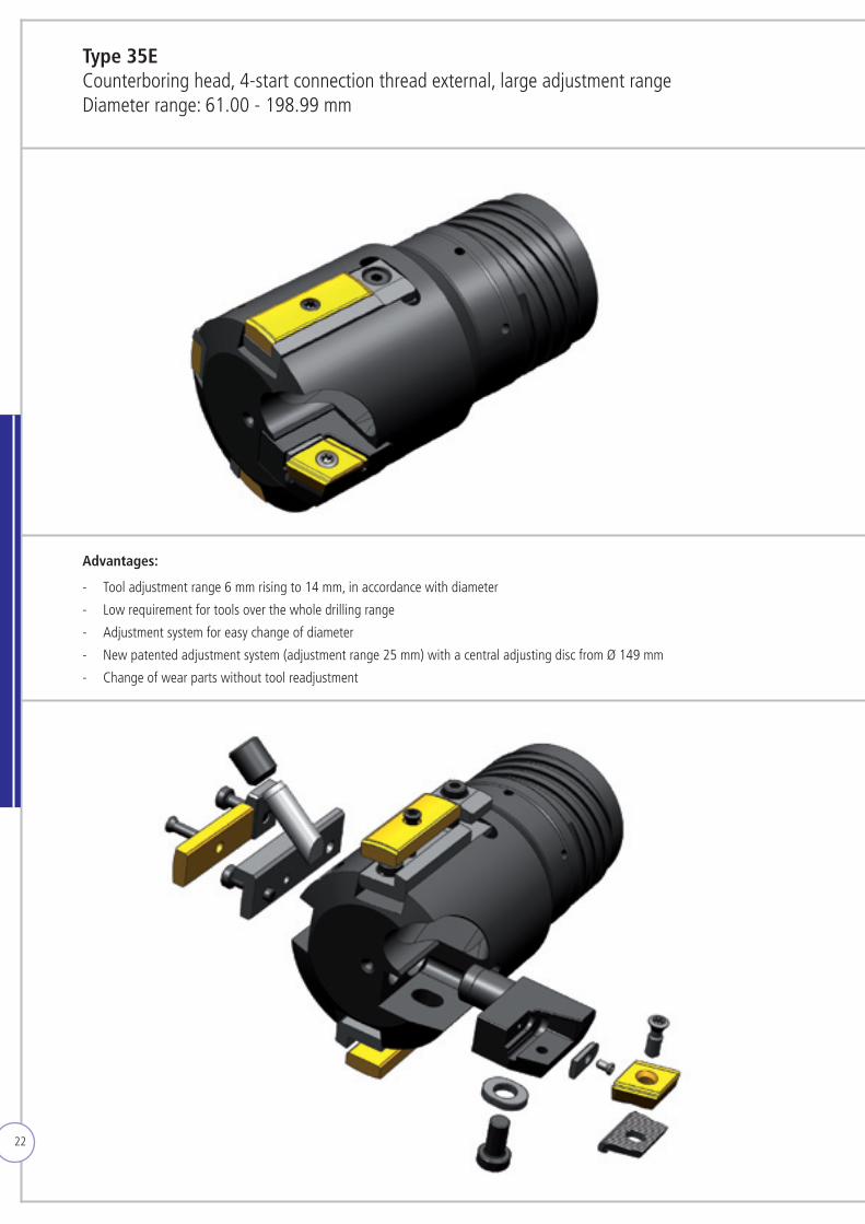
Advantages: - Tool adjustment range 6 mm rising to 14 mm, in accordance with diameter
- Low requirement for tools over the whole drilling range
- Adjustment system for easy change of diameter
- New patented adjustment system (adjustment range 25 mm) with a central adjusting disc from Ø 149 mm
- Change of wear parts without tool readjustment
Type 35ECounterboring head, 4-start connection thread external, large adjustment rangeDiameter range: 61.00 - 198.99 mm
23
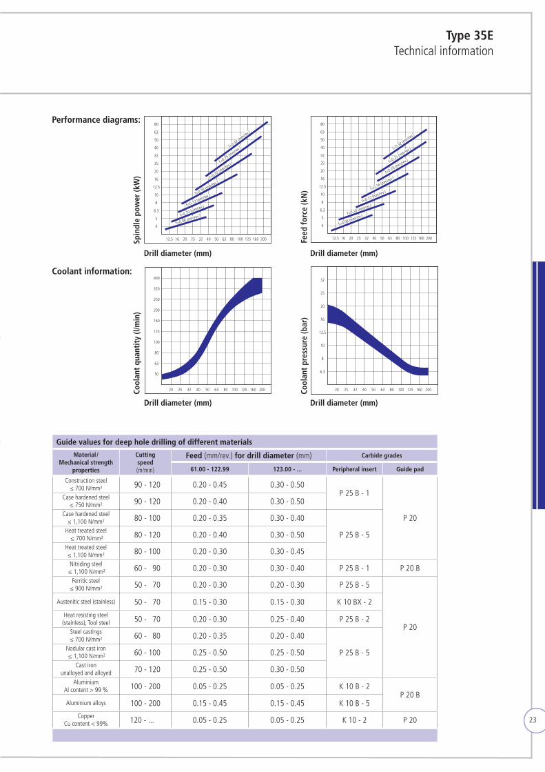
Type 35ETechnical information
Guide values for deep hole drilling of different materialsMaterial /
Mechanical strength properties
Cutting speed (m/min)
Feed (mm/rev.) for drill diameter (mm) Carbide grades
61.00 - 122.99 123.00 - ... Peripheral insert Guide pad
Construction steel≤ 700 N/mm² 190 - 120 0.20 - 0.45 0.30 - 0.50
P 25 B - 1
P 20
Case hardened steel≤ 750 N/mm² 190 - 120 0.20 - 0.40 0.30 - 0.50
Case hardened steel≤ 1,100 N/mm² 180 - 100 0.20 - 0.35 0.30 - 0.40
P 25 B - 5Heat treated steel ≤ 700 N/mm² 180 - 120 0.20 - 0.40 0.30 - 0.50
Heat treated steel ≤ 1,100 N/mm² 180 - 100 0.20 - 0.30 0.30 - 0.45Nitriding steel
≤ 1,100 N/mm² 160 - 190 0.20 - 0.30 0.30 - 0.40 P 25 B - 1 P 20 BFerritic steel
≤ 900 N/mm² 150 - 170 0.20 - 0.30 0.20 - 0.30 P 25 B - 5
P 20
Austenitic steel (stainless) 150 - 170 0.15 - 0.30 0.15 - 0.30 K 10 BX - 2
Heat resisting steel(stainless), Tool steel 150 - 170 0.20 - 0.30 0.25 - 0.40 P 25 B - 2
Steel castings ≤ 700 N/mm² 160 - 180 0.20 - 0.35 0.20 - 0.40
P 25 B - 5Nodular cast iron ≤ 1,100 N/mm² 160 - 100 0.25 - 0.50 0.25 - 0.50
Cast ironunalloyed and alloyed 170 - 120 0.25 - 0.50 0.30 - 0.50
AluminiumAl content > 99 % 100 - 200 0.05 - 0.25 0.05 - 0.25 K 10 B - 2
P 20 BAluminium alloys 100 - 200 0.15 - 0.45 0.15 - 0.45 K 10 B - 5
CopperCu content < 99% 120 - ... 0.05 - 0.25 0.05 - 0.25 K 10 - 2 P 20
12.5 16 20 25 32 40 50 63 80 100 125 160 200
5
6.3
8
10
12.5
16
20
25
32
40
50
63
80
4
f=0.32 (mm/rev
.)
f=0.25 (mm/rev
.)
f=0.20 (mm/rev
.)
f=0.16 (mm/rev.)
f=0.12 (mm/rev.)
f=0.10 (mm/rev.)
f=0.08 (mm/rev.)
12.5 16 20 25 32 40 50 63 80 100 125 160 200
5
6.3
8
10
12.5
16
20
25
32
40
50
63
80
4
f=0.32 (mm/rev
.)
f=0.25 (mm/rev
.)
f=0.20 (mm/rev.)
f=0.16 (mm/rev.)
f=0.12 (mm/rev.)
f=0.10 (mm/rev.)
f=0.08 (mm/rev.)
50
20 25 32 40 50 63 80 100 125 160 200
63
80
100
125
160
200
250
320
400
6.3
20 25 32 40 50 63 80 100 125 160 200
8
10
12.5
16
20
25
32
12.5 16 20 25 32 40 50 63 80 100 125 160 200
5
6.3
8
10
12.5
16
20
25
32
40
50
63
80
4
f=0.32 (mm/rev
.)
f=0.25 (mm/rev
.)
f=0.20 (mm/rev
.)
f=0.16 (mm/rev.)
f=0.12 (mm/rev.)
f=0.10 (mm/rev.)
f=0.08 (mm/rev.)
12.5 16 20 25 32 40 50 63 80 100 125 160 200
5
6.3
8
10
12.5
16
20
25
32
40
50
63
80
4
f=0.32 (mm/rev
.)
f=0.25 (mm/rev
.)
f=0.20 (mm/rev.)
f=0.16 (mm/rev.)
f=0.12 (mm/rev.)
f=0.10 (mm/rev.)
f=0.08 (mm/rev.)
50
20 25 32 40 50 63 80 100 125 160 200
63
80
100
125
160
200
250
320
400
6.3
20 25 32 40 50 63 80 100 125 160 200
8
10
12.5
16
20
25
32
12,5 16 20 25 32 40 50 63 80 100 125 160 200
5
6,3
8
10
12,5
16
20
25
32
40
50
63
80
4
f=0,32 (mm/U)
f=0,25 (mm/U)
f=0,20 (mm/U)
f=0,16 (mm/U)
f=0,12 (mm/U)
f=0,10 (mm/U)
f=0,08 (mm/U)
Antri
ebsle
istun
g Sp
inde
lmot
or (k
W)
12,5 16 20 25 32 40 50 63 80 100 125 160 200
5
6,3
8
10
12,5
16
20
25
32
40
50
63
80
4
f=0,32 (mm/U)
f=0,25 (mm/U)
f=0,20 (mm/U)
f=0,16 (mm/U)
f=0,12 (mm/U)
f=0,10 (mm/U)
f=0,08 (mm/U)
Vors
chub
kraf
t (kN
)
50
Kühl
schm
iers
toffm
enge
(l/m
in)
20 25 32 40 50 63 80 100 125 160 200
63
80
100
125
160
200
250
320
400
6,3
Kühl
schm
iers
toffd
ruck
(bar
)
20 25 32 40 50 63 80 100 125 160 200
8
10
12,5
16
20
25
32
12.5 16 20 25 32 40 50 63 80 100 125 160 200
5
6.3
8
10
12.5
16
20
25
32
40
50
63
80
4
f=0.32 (mm/rev
.)
f=0.25 (mm/rev
.)
f=0.20 (mm/rev
.)
f=0.16 (mm/rev.)
f=0.12 (mm/rev.)
f=0.10 (mm/rev.)
f=0.08 (mm/rev.)
12.5 16 20 25 32 40 50 63 80 100 125 160 200
5
6.3
8
10
12.5
16
20
25
32
40
50
63
80
4
f=0.32 (mm/rev
.)
f=0.25 (mm/rev
.)
f=0.20 (mm/rev.)
f=0.16 (mm/rev.)
f=0.12 (mm/rev.)
f=0.10 (mm/rev.)
f=0.08 (mm/rev.)
50
20 25 32 40 50 63 80 100 125 160 200
63
80
100
125
160
200
250
320
400
6.3
20 25 32 40 50 63 80 100 125 160 200
8
10
12.5
16
20
25
32
Performance diagrams:
Coolant information:
Spin
dle
pow
er (k
W)
Cool
ant
quan
tity
(l/m
in)
Feed
forc
e (k
N)
Cool
ant
pres
sure
(bar
)
Drill diameter (mm)
Drill diameter (mm)
Drill diameter (mm)
Drill diameter (mm)
24
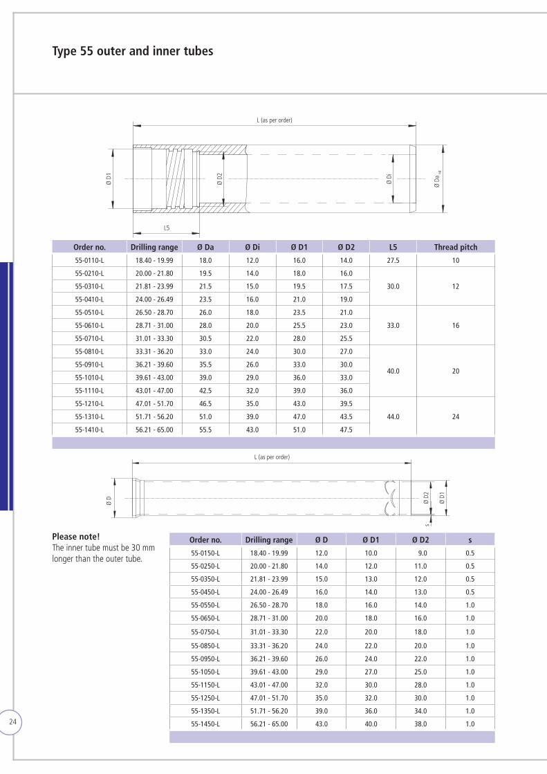
Type 55 outer and inner tubes
Order no. Drilling range Ø Da Ø Di Ø D1 Ø D2 L5 Thread pitch
55-0110-L 18.40 - 19.99 18.0 12.0 16.0 14.0 27.5 10
55-0210-L 20.00 - 21.80 19.5 14.0 18.0 16.0
30.0 1255-0310-L 21.81 - 23.99 21.5 15.0 19.5 17.5
55-0410-L 24.00 - 26.49 23.5 16.0 21.0 19.0
55-0510-L 26.50 - 28.70 26.0 18.0 23.5 21.0
33.0 1655-0610-L 28.71 - 31.00 28.0 20.0 25.5 23.0
55-0710-L 31.01 - 33.30 30.5 22.0 28.0 25.5
55-0810-L 33.31 - 36.20 33.0 24.0 30.0 27.0
40.0 2055-0910-L 36.21 - 39.60 35.5 26.0 33.0 30.0
55-1010-L 39.61 - 43.00 39.0 29.0 36.0 33.0
55-1110-L 43.01 - 47.00 42.5 32.0 39.0 36.0
55-1210-L 47.01 - 51.70 46.5 35.0 43.0 39.5
44.0 2455-1310-L 51.71 - 56.20 51.0 39.0 47.0 43.5
55-1410-L 56.21 - 65.00 55.5 43.0 51.0 47.5
Order no. Drilling range Ø D Ø D1 Ø D2 s
55-0150-L 18.40 - 19.99 12.0 10.0 9.0 0.5
55-0250-L 20.00 - 21.80 14.0 12.0 11.0 0.5
55-0350-L 21.81 - 23.99 15.0 13.0 12.0 0.5
55-0450-L 24.00 - 26.49 16.0 14.0 13.0 0.5
55-0550-L 26.50 - 28.70 18.0 16.0 14.0 1.0
55-0650-L 28.71 - 31.00 20.0 18.0 16.0 1.0
55-0750-L 31.01 - 33.30 22.0 20.0 18.0 1.0
55-0850-L 33.31 - 36.20 24.0 22.0 20.0 1.0
55-0950-L 36.21 - 39.60 26.0 24.0 22.0 1.0
55-1050-L 39.61 - 43.00 29.0 27.0 25.0 1.0
55-1150-L 43.01 - 47.00 32.0 30.0 28.0 1.0
55-1250-L 47.01 - 51.70 35.0 32.0 30.0 1.0
55-1350-L 51.71 - 56.20 39.0 36.0 34.0 1.0
55-1450-L 56.21 - 65.00 43.0 40.0 38.0 1.0
Please note! The inner tube must be 30 mm longer than the outer tube.
L (as per order)
Ø D
1
Ø D
2
Ø D
i
Ø D
a h8
L5
Ø D Ø D
2
Ø D
1
L (as per order)
s
25
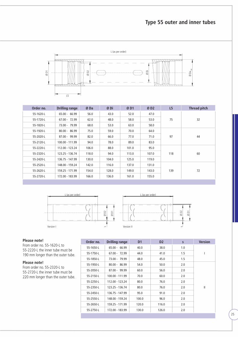
Type 55 outer and inner tubes
Order no. Drilling range Ø Da Ø Di Ø D1 Ø D2 L5 Thread pitch
55-1620-L 165.00 - 166.99 156.0 143.0 152.0 147.0
75 3255-1720-L 167.00 - 172.99 162.0 148.0 158.0 153.0
55-1820-L 173.00 - 179.99 168.0 153.0 163.0 158.0
55-1920-L 180.00 - 186.99 175.0 159.0 170.0 164.0
97 4455-2020-L 187.00 - 199.99 182.0 166.0 177.0 171.0
55-2120-L 100.00 - 111.99 194.0 178.0 189.0 183.0
55-2220-L 112.00 - 123.24 106.0 188.0 101.0 195.0
118 6055-2320-L 123.25 - 136.74 118.0 194.0 113.0 107.0
55-2420-L 136.75 - 147.99 130.0 104.0 125.0 119.0
55-2520-L 148.00 - 159.24 142.0 116.0 137.0 131.0
139 7255-2620-L 159.25 - 171.99 154.0 128.0 149.0 143.0
55-2720-L 172.00 - 183.99 166.0 136.0 161.0 155.0
Order no. Drilling range D1 D2 s Version
55-1650-L 165.00 - 166.99 40.0 38.0 1.0
I55-1750-L 167.00 - 172.99 44.0 41.0 1.5
55-1850-L 173.00 - 179.99 48.0 45.0 1.5
55-1950-L 180.00 - 186.99 54.0 50.0 2.0
II
55-2050-L 187.00 - 199.99 60.0 56.0 2.0
55-2150-L 100.00 - 111.99 70.0 60.0 2.0
55-2250-L 112.00 - 123.24 80.0 76.0 2.0
55-2350-L 123.25 - 136.74 80.0 76.0 2.0
55-2450-L 136.75 - 147.99 95.0 91.0 2.0
55-2550-L 148.00 - 159.24 100.0 96.0 2.0
55-2650-L 159.25 - 171.99 120.0 116.0 2.0
55-2750-L 172.00 - 183.99 130.0 126.0 2.0
Please note! From order no. 55-1620-L to 55-2220-L the inner tube must be 190 mm longer than the outer tube.
Please note! From order no. 55-2320-L to 55-2720-L the inner tube must be 220 mm longer than the outer tube.
L (as per order)
Ø D
1
Ø D
2
Ø D
i
Ø D
a h8
L5
L (as per order) L (as per order)
Ø D
2
Ø D
1
s
Ø D
2
Ø D
1
sVersion I Version II
26
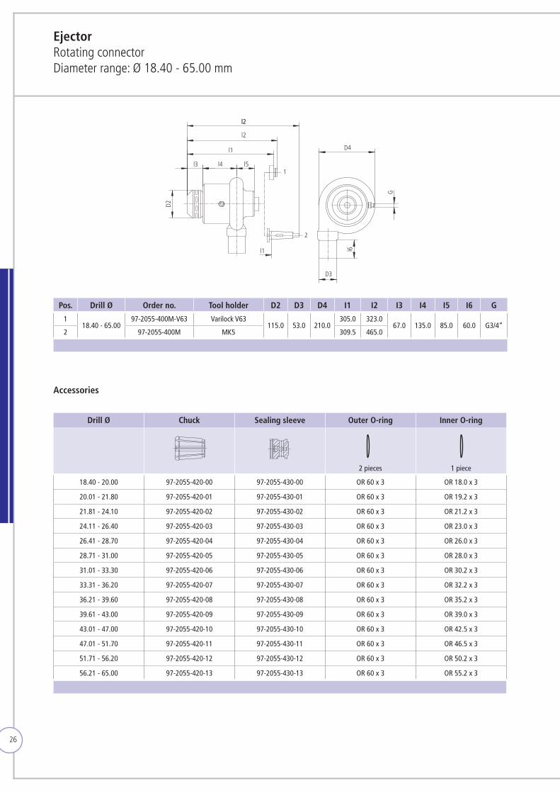
EjectorRotating connectorDiameter range: Ø 18.40 - 65.00 mm
Pos. Drill Ø Order no. Tool holder D2 D3 D4 I1 I2 I3 I4 I5 I6 G
118.40 - 65.00
97-2055-400M-V63 Varilock V63115.0 53.0 210.0
305.0 323.067.0 135.0 85.0 60.0 G3/4“
2 97-2055-400M MK5 309.5 465.0
D2
l2l2
l2
l1
l3 l4 l51
2
l1
D4
G
D3
l6
Accessories
Drill Ø Chuck Sealing sleeve Outer O-ring Inner O-ring
2 pieces 1 piece
18.40 - 20.00 97-2055-420-00 97-2055-430-00 OR 60 x 3 OR 18.0 x 3
20.01 - 21.80 97-2055-420-01 97-2055-430-01 OR 60 x 3 OR 19.2 x 3
21.81 - 24.10 97-2055-420-02 97-2055-430-02 OR 60 x 3 OR 21.2 x 3
24.11 - 26.40 97-2055-420-03 97-2055-430-03 OR 60 x 3 OR 23.0 x 3
26.41 - 28.70 97-2055-420-04 97-2055-430-04 OR 60 x 3 OR 26.0 x 3
28.71 - 31.00 97-2055-420-05 97-2055-430-05 OR 60 x 3 OR 28.0 x 3
31.01 - 33.30 97-2055-420-06 97-2055-430-06 OR 60 x 3 OR 30.2 x 3
33.31 - 36.20 97-2055-420-07 97-2055-430-07 OR 60 x 3 OR 32.2 x 3
36.21 - 39.60 97-2055-420-08 97-2055-430-08 OR 60 x 3 OR 35.2 x 3
39.61 - 43.00 97-2055-420-09 97-2055-430-09 OR 60 x 3 OR 39.0 x 3
43.01 - 47.00 97-2055-420-10 97-2055-430-10 OR 60 x 3 OR 42.5 x 3
47.01 - 51.70 97-2055-420-11 97-2055-430-11 OR 60 x 3 OR 46.5 x 3
51.71 - 56.20 97-2055-420-12 97-2055-430-12 OR 60 x 3 OR 50.2 x 3
56.21 - 65.00 97-2055-420-13 97-2055-430-13 OR 60 x 3 OR 55.2 x 3
27
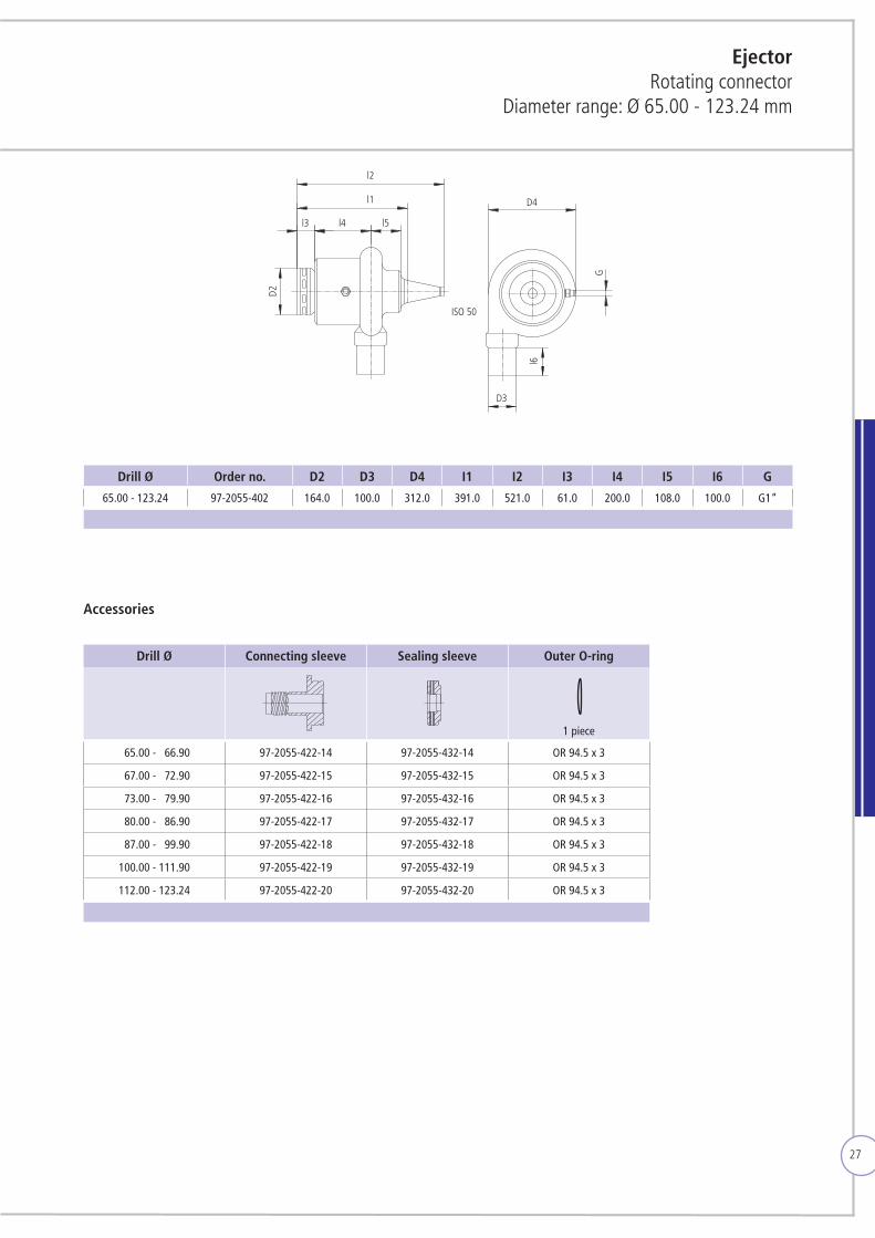
Drill Ø Order no. D2 D3 D4 I1 I2 I3 I4 I5 I6 G
65.00 - 123.24 97-2055-402 164.0 100.0 312.0 391.0 521.0 61.0 200.0 108.0 100.0 G1“
D2
l2
l1
l3 l4 l5
ISO 50
G
D4
l6
D3
Ejector Rotating connector
Diameter range: Ø 65.00 - 123.24 mm
Accessories
Drill Ø Connecting sleeve Sealing sleeve Outer O-ring
1 piece
165.00 - 166.90 97-2055-422-14 97-2055-432-14 OR 94.5 x 3
167.00 - 172.90 97-2055-422-15 97-2055-432-15 OR 94.5 x 3
173.00 - 179.90 97-2055-422-16 97-2055-432-16 OR 94.5 x 3
180.00 - 186.90 97-2055-422-17 97-2055-432-17 OR 94.5 x 3
187.00 - 199.90 97-2055-422-18 97-2055-432-18 OR 94.5 x 3
100.00 - 111.90 97-2055-422-19 97-2055-432-19 OR 94.5 x 3
112.00 - 123.24 97-2055-422-20 97-2055-432-20 OR 94.5 x 3
28
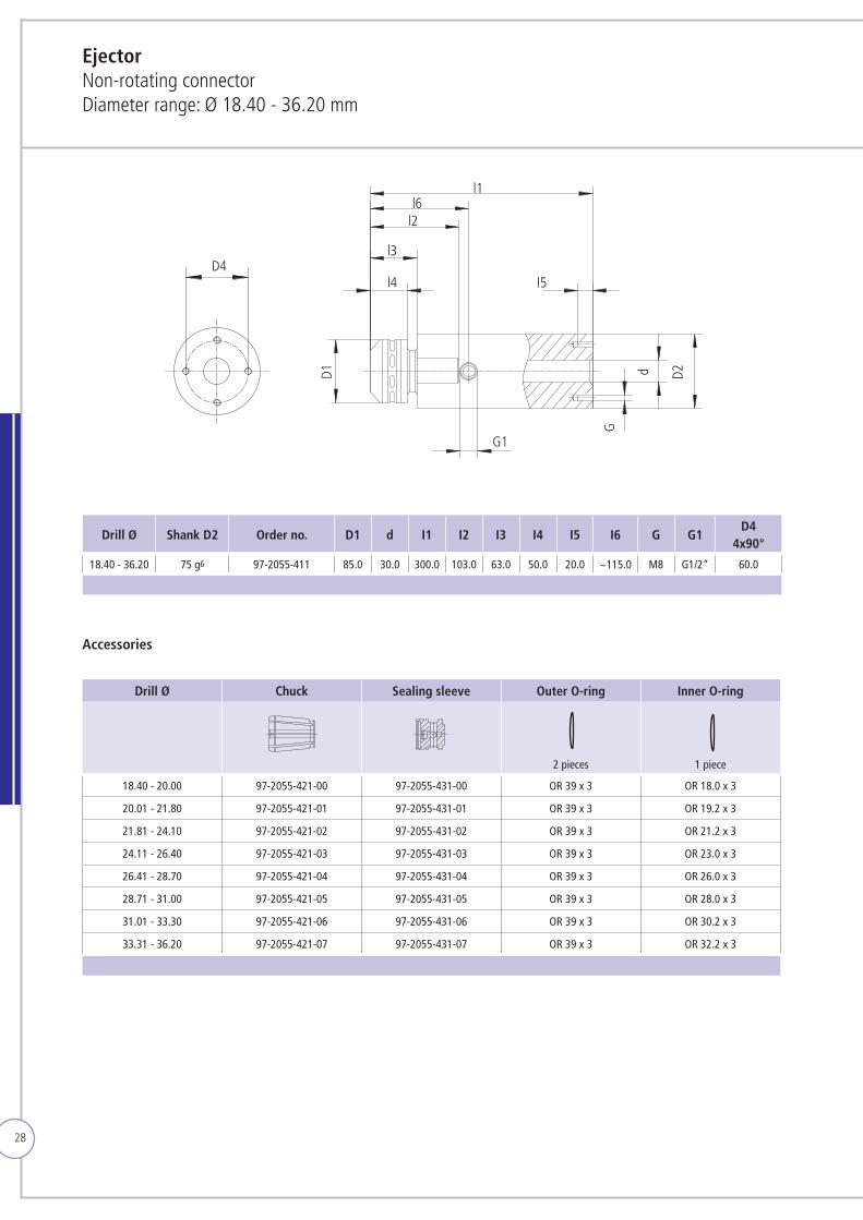
Drill Ø Shank D2 Order no. D1 d I1 I2 I3 I4 I5 I6 G G1D4
4x90°
18.40 - 36.20 75 g6 97-2055-411 85.0 30.0 300.0 103.0 63.0 50.0 20.0 ~115.0 M8 G1/2“ 60.0
l1
l2
l3
l4 l5
G
G1
D1 d D2
D4
Accessories
Drill Ø Chuck Sealing sleeve Outer O-ring Inner O-ring
2 pieces 1 piece
18.40 - 20.00 97-2055-421-00 97-2055-431-00 OR 39 x 3 OR 18.0 x 3
20.01 - 21.80 97-2055-421-01 97-2055-431-01 OR 39 x 3 OR 19.2 x 3
21.81 - 24.10 97-2055-421-02 97-2055-431-02 OR 39 x 3 OR 21.2 x 3
24.11 - 26.40 97-2055-421-03 97-2055-431-03 OR 39 x 3 OR 23.0 x 3
26.41 - 28.70 97-2055-421-04 97-2055-431-04 OR 39 x 3 OR 26.0 x 3
28.71 - 31.00 97-2055-421-05 97-2055-431-05 OR 39 x 3 OR 28.0 x 3
31.01 - 33.30 97-2055-421-06 97-2055-431-06 OR 39 x 3 OR 30.2 x 3
33.31 - 36.20 97-2055-421-07 97-2055-431-07 OR 39 x 3 OR 32.2 x 3
EjectorNon-rotating connectorDiameter range: Ø 18.40 - 36.20 mm
l6
29
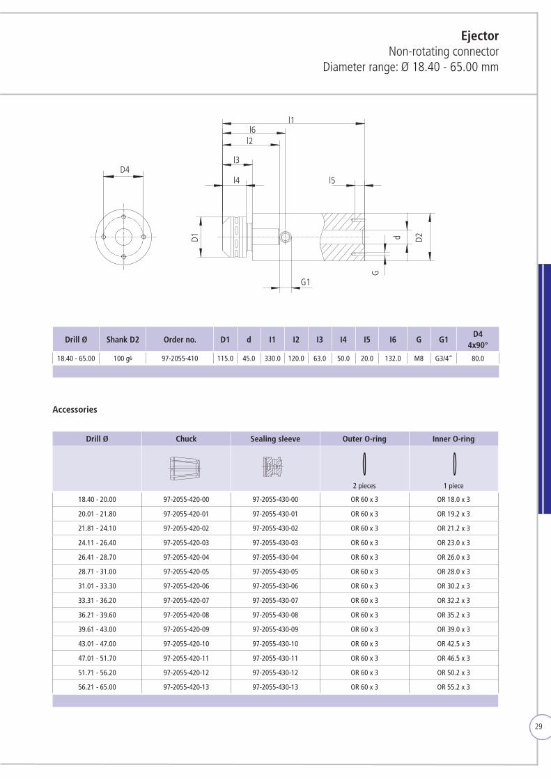
EjectorNon-rotating connector
Diameter range: Ø 18.40 - 65.00 mm
Drill Ø Shank D2 Order no. D1 d I1 I2 I3 I4 I5 I6 G G1D4
4x90°
18.40 - 65.00 100 g6 97-2055-410 115.0 45.0 330.0 120.0 63.0 50.0 20.0 132.0 M8 G3/4“ 80.0
Accessories
Drill Ø Chuck Sealing sleeve Outer O-ring Inner O-ring
2 pieces 1 piece
18.40 - 20.00 97-2055-420-00 97-2055-430-00 OR 60 x 3 OR 18.0 x 3
20.01 - 21.80 97-2055-420-01 97-2055-430-01 OR 60 x 3 OR 19.2 x 3
21.81 - 24.10 97-2055-420-02 97-2055-430-02 OR 60 x 3 OR 21.2 x 3
24.11 - 26.40 97-2055-420-03 97-2055-430-03 OR 60 x 3 OR 23.0 x 3
26.41 - 28.70 97-2055-420-04 97-2055-430-04 OR 60 x 3 OR 26.0 x 3
28.71 - 31.00 97-2055-420-05 97-2055-430-05 OR 60 x 3 OR 28.0 x 3
31.01 - 33.30 97-2055-420-06 97-2055-430-06 OR 60 x 3 OR 30.2 x 3
33.31 - 36.20 97-2055-420-07 97-2055-430-07 OR 60 x 3 OR 32.2 x 3
36.21 - 39.60 97-2055-420-08 97-2055-430-08 OR 60 x 3 OR 35.2 x 3
39.61 - 43.00 97-2055-420-09 97-2055-430-09 OR 60 x 3 OR 39.0 x 3
43.01 - 47.00 97-2055-420-10 97-2055-430-10 OR 60 x 3 OR 42.5 x 3
47.01 - 51.70 97-2055-420-11 97-2055-430-11 OR 60 x 3 OR 46.5 x 3
51.71 - 56.20 97-2055-420-12 97-2055-430-12 OR 60 x 3 OR 50.2 x 3
56.21 - 65.00 97-2055-420-13 97-2055-430-13 OR 60 x 3 OR 55.2 x 3
l1
l2
l3
l4 l5
G
G1
D1 d D2
l6
D4
30
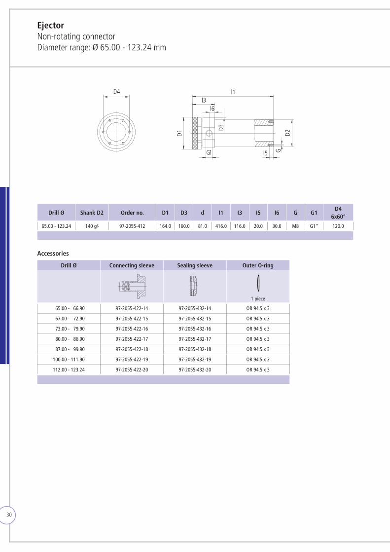
Drill Ø Shank D2 Order no. D1 D3 d I1 I3 I5 I6 G G1D4
6x60°
65.00 - 123.24 140 g6 97-2055-412 164.0 160.0 81.0 416.0 116.0 20.0 30.0 M8 G1“ 120.0
D4 l1l3
l6
l5
D1 D2G
D3
G1
EjectorNon-rotating connectorDiameter range: Ø 65.00 - 123.24 mm
Accessories
Drill Ø Connecting sleeve Sealing sleeve Outer O-ring
1 piece
165.00 - 166.90 97-2055-422-14 97-2055-432-14 OR 94.5 x 3
167.00 - 172.90 97-2055-422-15 97-2055-432-15 OR 94.5 x 3
173.00 - 179.90 97-2055-422-16 97-2055-432-16 OR 94.5 x 3
180.00 - 186.90 97-2055-422-17 97-2055-432-17 OR 94.5 x 3
187.00 - 199.90 97-2055-422-18 97-2055-432-18 OR 94.5 x 3
100.00 - 111.90 97-2055-422-19 97-2055-432-19 OR 94.5 x 3
112.00 - 123.24 97-2055-422-20 97-2055-432-20 OR 94.5 x 3
31
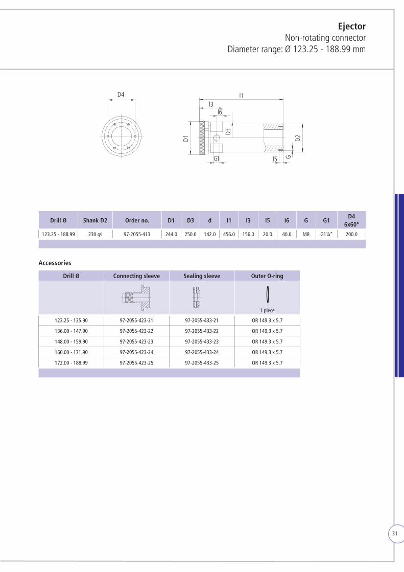
Drill Ø Shank D2 Order no. D1 D3 d I1 I3 I5 I6 G G1D4
6x60°
123.25 - 188.99 230 g6 97-2055-413 244.0 250.0 142.0 456.0 156.0 20.0 40.0 M8 G1¼“ 200.0
D4 l1l3
l6
l5
D1 D2G
D3
G1
EjectorNon-rotating connector
Diameter range: Ø 123.25 - 188.99 mm
Accessories
Drill Ø Connecting sleeve Sealing sleeve Outer O-ring
1 piece
123.25 - 135.90 97-2055-423-21 97-2055-433-21 OR 149.3 x 5.7
136.00 - 147.90 97-2055-423-22 97-2055-433-22 OR 149.3 x 5.7
148.00 - 159.90 97-2055-423-23 97-2055-433-23 OR 149.3 x 5.7
160.00 - 171.90 97-2055-423-24 97-2055-433-24 OR 149.3 x 5.7
172.00 - 188.99 97-2055-423-25 97-2055-433-25 OR 149.3 x 5.7
32
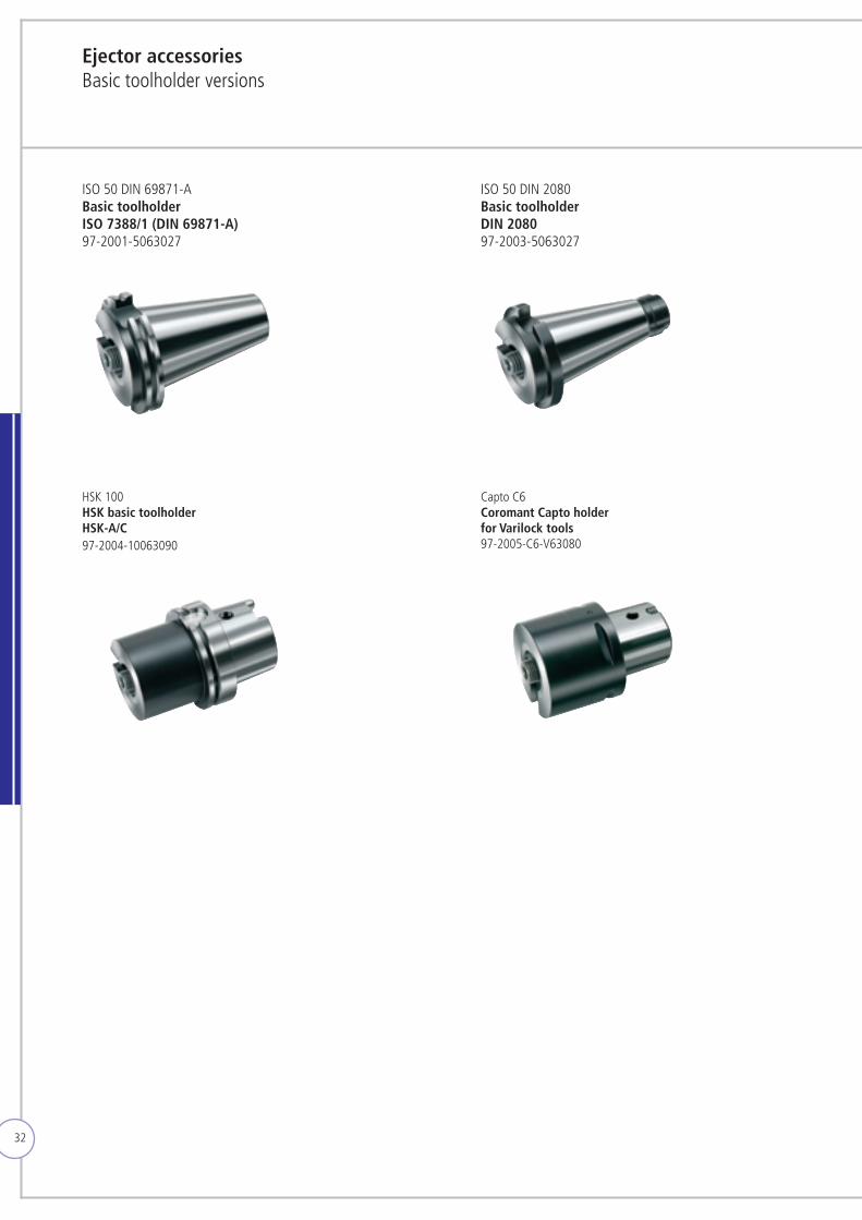
Ejector accessoriesBasic toolholder versions
ISO 50 DIN 69871-A Basic toolholderISO 7388/1 (DIN 69871-A)97-2001-5063027
ISO 50 DIN 2080Basic toolholderDIN 208097-2003-5063027
HSK 100 HSK basic toolholderHSK-A/C 97-2004-10063090
Capto C6Coromant Capto holderfor Varilock tools97-2005-C6-V63080
33
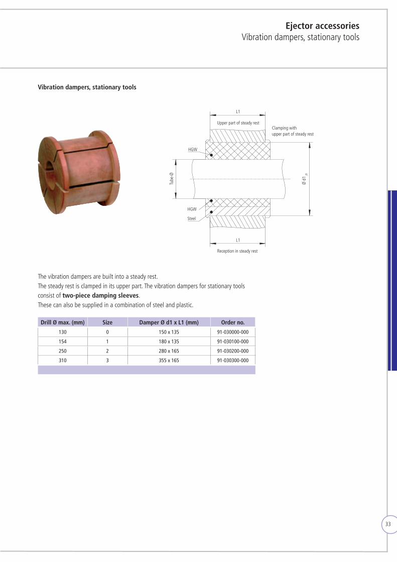
Vibration dampers, stationary tools
Ejector accessoriesVibration dampers, stationary tools
Drill Ø max. (mm) Size Damper Ø d1 x L1 (mm) Order no.
130 0 150 x 135 91-030000-000
154 1 180 x 135 91-030100-000
250 2 280 x 165 91-030200-000
310 3 355 x 165 91-030300-000
Clamping with upper part of steady rest
HGW
HGW
Steel
Reception in steady rest
Ø d
1 j6
Tube
-Ø
L1
L1
Upper part of steady rest
The vibration dampers are built into a steady rest.The steady rest is clamped in its upper part. The vibration dampers for stationary tools consist of two-piece damping sleeves. These can also be supplied in a combination of steel and plastic.
34
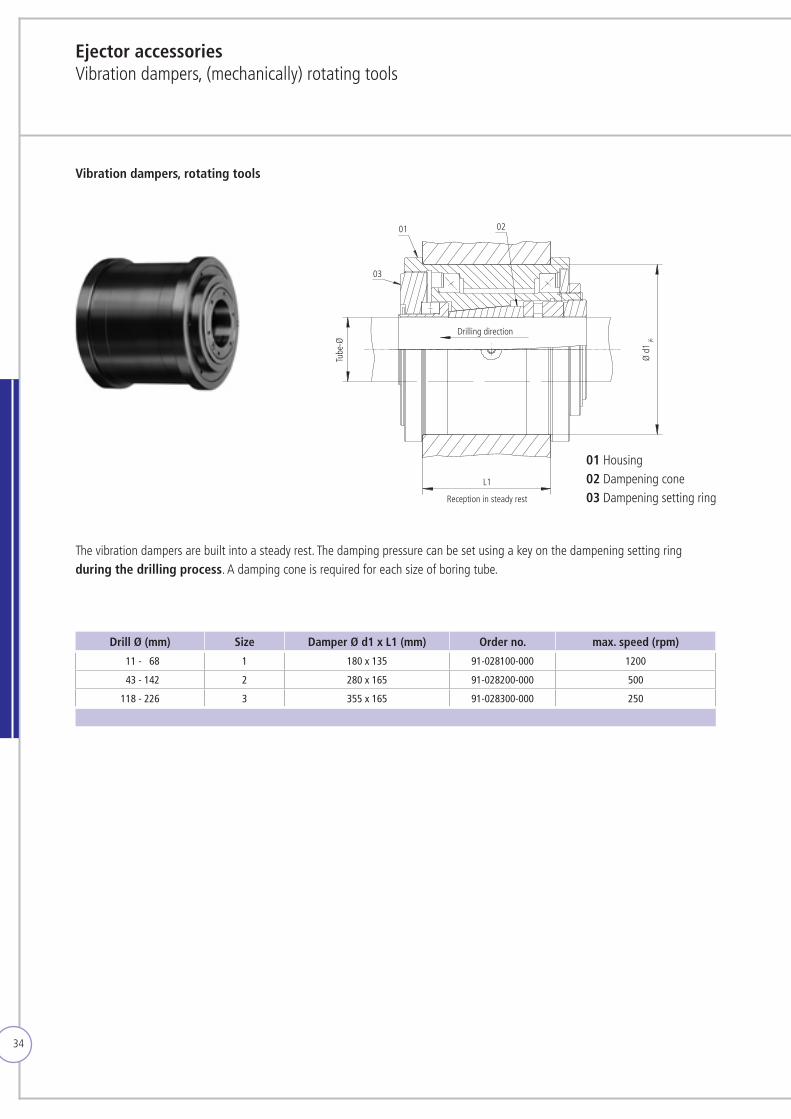
Ejector accessoriesVibration dampers, (mechanically) rotating tools
Vibration dampers, rotating tools
Drill Ø (mm) Size Damper Ø d1 x L1 (mm) Order no. max. speed (rpm)
111 - 168 1 180 x 135 91-028100-000 1200
143 - 142 2 280 x 165 91-028200-000 500
118 - 226 3 355 x 165 91-028300-000 250
Ø d
1 j6
Tube
-ØDrilling direction
Reception in steady rest
0201
03
L1
The vibration dampers are built into a steady rest. The damping pressure can be set using a key on the dampening setting ring during the drilling process. A damping cone is required for each size of boring tube.
01 Housing 02 Dampening cone 03 Dampening setting ring
35
Ejector accessories
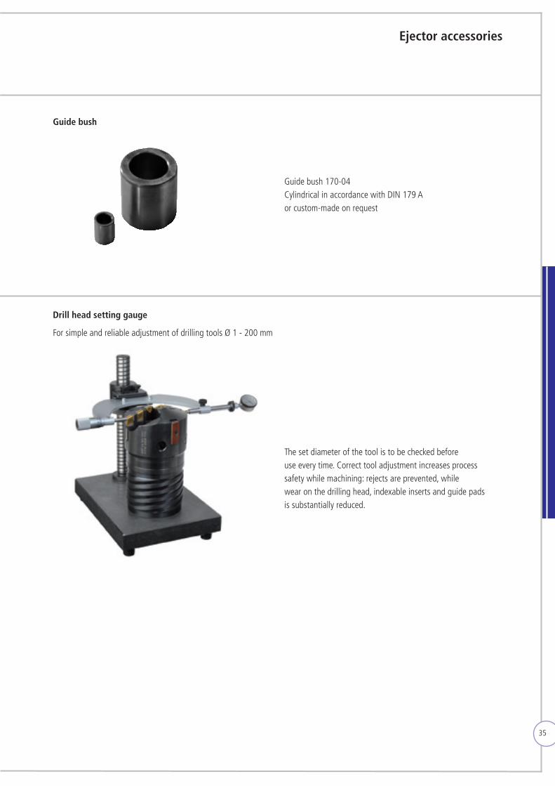
Guide bush
Guide bush 170-04 Cylindrical in accordance with DIN 179 A or custom-made on request
Drill head setting gauge
For simple and reliable adjustment of drilling tools Ø 1 - 200 mm
The set diameter of the tool is to be checked before use every time. Correct tool adjustment increases process safety while machining: rejects are prevented, while wear on the drilling head, indexable inserts and guide pads is substantially reduced.
36
Technical appendix
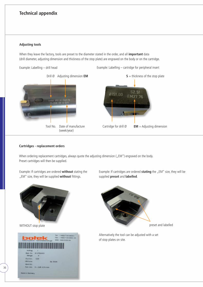
Adjusting tools
Cartridges - replacement orders
Whentheyleavethefactory,toolsarepresettothediameterstatedintheorder,andallimportant data (drill diameter, adjusting dimension and thickness of the stop plate) are engraved on the body or on the cartridge.
Whenorderingreplacementcartridges,alwaysquotetheadjusting dimension („EM“) engraved on the body. Preset cartridges will then be supplied.
Example: Labelling – drill head Example: Labelling – cartridge for peripheral insert
Example: If cartridges are ordered without stating the „EM“ size, they will be supplied without fittings.
Drill Ø S = thickness of the stop plateAdjusting dimension EM
EM = Adjusting dimensionTool No. Date of manufacture (week/year)
preset and labelled
Cartridge for drill Ø
WITHOUTstopplate
Example: If cartridges are ordered stating the „EM“ size, they will be supplied preset and labelled.
Alternatively the tool can be adjusted with a set of stop plates on site.
37
Technical appendix
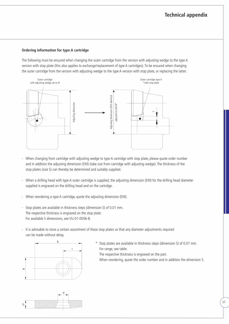
Ordering information for type A cartridge
The following must be ensured when changing the outer cartridge from the version with adjusting wedge to the type A version with stop plate (this also applies to exchange/replacement of type A cartridges). To be ensured when changing the outer cartridge from the version with adjusting wedge to the type A version with stop plate, or replacing the latter.
- WhenchangingfromcartridgewithadjustingwedgetotypeAcartridgewithstopplate,pleasequoteordernumber and in addition the adjusting dimension (EM) (take size from cartridge with adjusting wedge). The thickness of the stop plates (size S) can thereby be determined and suitably supplied.
- WhenadrillingheadwithtypeAoutercartridgeissupplied,theadjustingdimension(EM)forthedrillingheaddiameter supplied is engraved on the drilling head and on the cartridge.
- WhenreorderingatypeAcartridge,quotetheadjustingdimension(EM).
- Stop plates are available in thickness steps (dimension S) of 0.01 mm. The respective thickness is engraved on the stop plate. For available S dimensions, see VU-01-0056-B.
- It is advisable to store a certain assortment of these stop plates so that any diameter adjustments required can be made without delay.
Outer cartridge with adjusting wedge set to Ø
Outer cartridge type A*with stop plate
d
S*B
I
* Stop plates are available in thickness steps (dimension S) of 0.01 mm. For range, see table. The respective thickness is engraved on the part. Whenreordering,quotetheordernumberandinadditionthedimensionS.
Adju
stin
g di
men
sion
Adju
stin
g di
men
sion
(EM
) ide
ntica
l
adju
sted
to d
rill Ø
*
S
38
Technical appendix
Changing the diameter of drill head
By replacing the accessories the diameter can be changed. Depending on the type of tool, stop plate, guide pads and cartridge of peripheral insert must be replaced.
Stop plate - available in increments of 0.01 mmCartridge - please choose according to information given in our catalogues.Guide pads - are manufactured on diameter, alternatively shims in thickness of 0.025, 0.05, 0.1 and 0.25 mm can be supplied. Other dimensions must be sourced in locally.
When re-ordering accessories please always state technical details.
Drill heads without cartridge (e.g. type 60) dimension „S“ and the drill Ø Drill heads with cartridge (e.g. type 42) adjusting dimension „EM“ and the drill Ø
kk
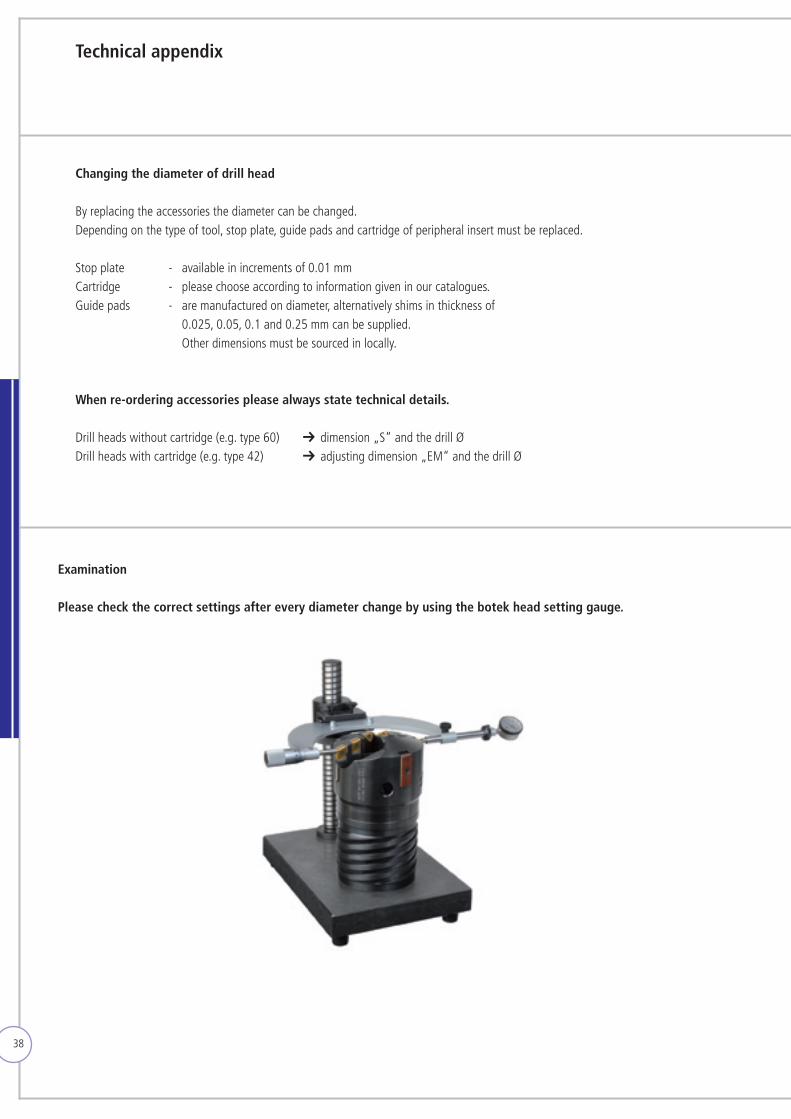
Examination
Please check the correct settings after every diameter change by using the botek head setting gauge.
39
Technical appendix Ejector process
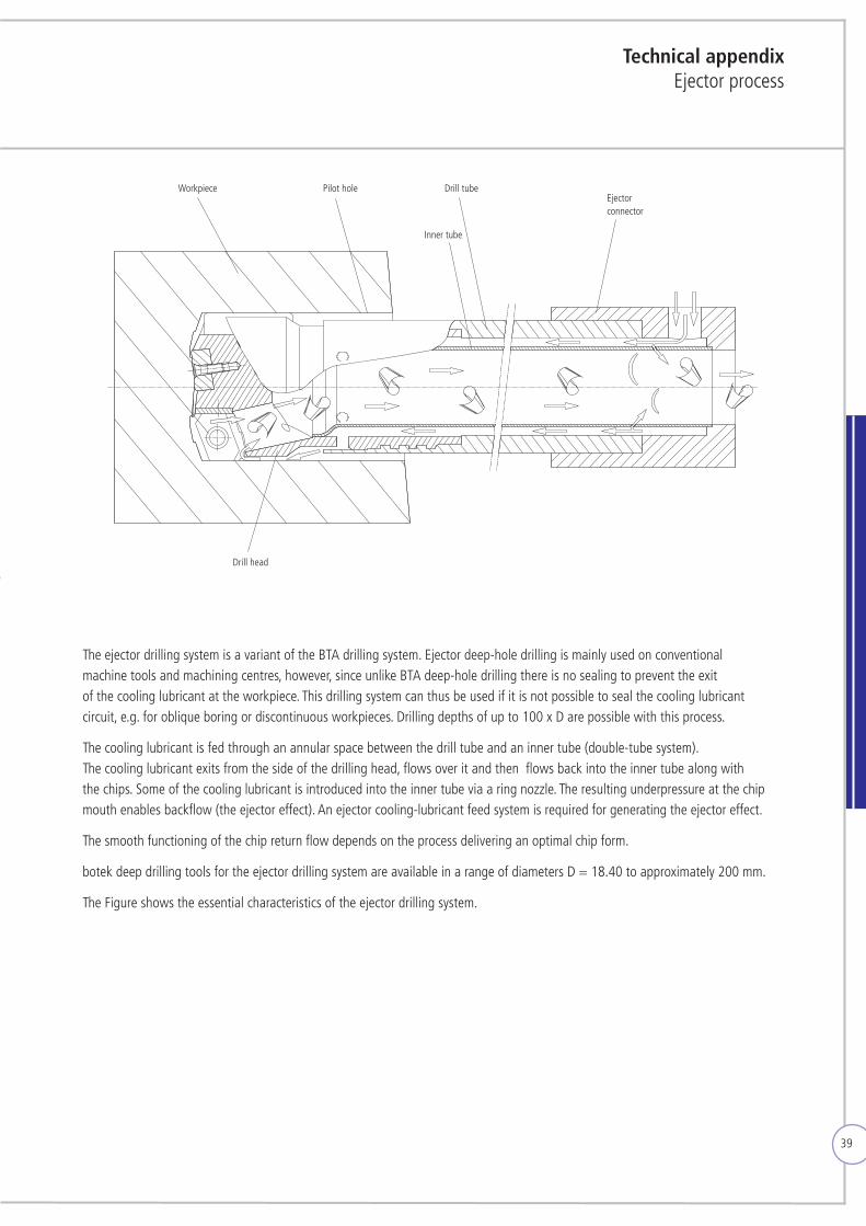
The ejector drilling system is a variant of the BTA drilling system. Ejector deep-hole drilling is mainly used on conventional machine tools and machining centres, however, since unlike BTA deep-hole drilling there is no sealing to prevent the exit of the cooling lubricant at the workpiece. This drilling system can thus be used if it is not possible to seal the cooling lubricant circuit, e.g. for oblique boring or discontinuous workpieces. Drilling depths of up to 100 x D are possible with this process.
The cooling lubricant is fed through an annular space between the drill tube and an inner tube (double-tube system). The cooling lubricant exits from the side of the drilling head, flows over it and then flows back into the inner tube along with the chips. Some of the cooling lubricant is introduced into the inner tube via a ring nozzle. The resulting underpressure at the chip mouth enables backflow (the ejector effect). An ejector cooling-lubricant feed system is required for generating the ejector effect.
The smooth functioning of the chip return flow depends on the process delivering an optimal chip form.
botek deep drilling tools for the ejector drilling system are available in a range of diameters D = 18.40 to approximately 200 mm.
The Figure shows the essential characteristics of the ejector drilling system.
Workpiece Pilot hole Drill tube
Drill head
Inner tube
Ejector connector
40
Technical appendixApplication on a lathe
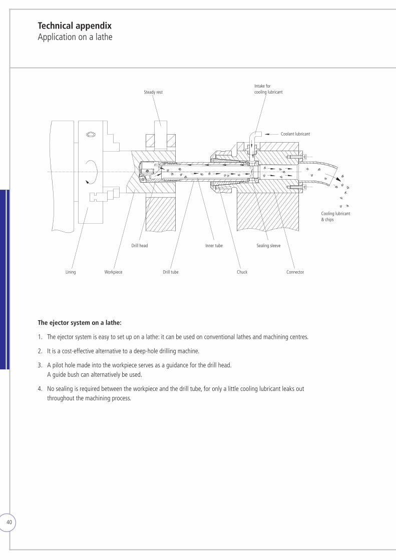
The ejector system on a lathe:
1. The ejector system is easy to set up on a lathe: it can be used on conventional lathes and machining centres.
2. It is a cost-effective alternative to a deep-hole drilling machine.
3. A pilot hole made into the workpiece serves as a guidance for the drill head. A guide bush can alternatively be used.
4. No sealing is required between the workpiece and the drill tube, for only a little cooling lubricant leaks out throughout the machining process.
Steady restIntake for cooling lubricant
Coolant lubricant
Lining Workpiece
Drill head
Drill tube
Inner tube Sealing sleeve
Chuck Connector
Cooling lubricant & chips
41
Technical appendixApplication on a machining centre
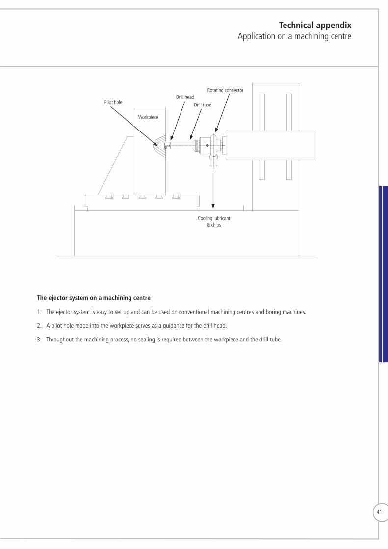
The ejector system on a machining centre
1. The ejector system is easy to set up and can be used on conventional machining centres and boring machines.
2. A pilot hole made into the workpiece serves as a guidance for the drill head.
3. Throughout the machining process, no sealing is required between the workpiece and the drill tube.
Cooling lubricant & chips
Workpiece
Drill tube
Drill headRotating connector
Pilot hole

42
InformationPilot hole /guide bush
Dimensions for the guide hole
The pilot hole should be slightly larger as the diameter of the drill head (recommended tolerance: F7). CAUTION: The drill tube must enter into the pilot hole by at least 5 mm.
Positioning of the guide bush for ejector drilling
No sealing is required between the workpiece and the guide bush in the ejector system. This guide bush should be as close as possible to the
workpiece. To guarantee good boring, the distance should not exceed 1.0 mm.
For efficiant coolant supply the drill bush should be at least 5 mm longer than the length to which the drill head extends in front of the drill tube.
If necessary, the angle of workpiece and drill bush should correspond.
max. 1 mm
min. 5 mm
D F7
min. 5 mm
D F7
min. 5 mm
D F7
43
Information Cooling system
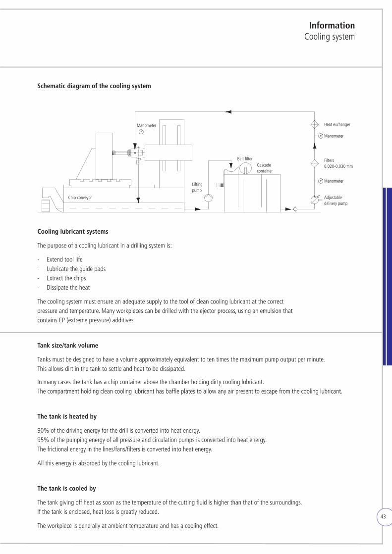
Cooling lubricant systems
The purpose of a cooling lubricant in a drilling system is:
- Extend tool life - Lubricate the guide pads - Extract the chips - Dissipate the heat
The cooling system must ensure an adequate supply to the tool of clean cooling lubricant at the correct pressure and temperature. Many workpieces can be drilled with the ejector process, using an emulsion that contains EP (extreme pressure) additives.
Tank size/tank volume
Tanks must be designed to have a volume approximately equivalent to ten times the maximum pump output per minute. This allows dirt in the tank to settle and heat to be dissipated. In many cases the tank has a chip container above the chamber holding dirty cooling lubricant. The compartment holding clean cooling lubricant has baffle plates to allow any air present to escape from the cooling lubricant.
The tank is heated by
90% of the driving energy for the drill is converted into heat energy. 95% of the pumping energy of all pressure and circulation pumps is converted into heat energy. The frictional energy in the lines/fans/filters is converted into heat energy.
All this energy is absorbed by the cooling lubricant.
The tank is cooled by
The tank giving off heat as soon as the temperature of the cutting fluid is higher than that of the surroundings. If the tank is enclosed, heat loss is greatly reduced.
The workpiece is generally at ambient temperature and has a cooling effect.
Schematic diagram of the cooling system
Chip conveyor
Lifting pump
Belt filterCascade container
Manometer
Manometer
Adjustable delivery pump
Filters 0.020-0.030 mm
Heat exchangerManometer
44
Heat exchangers
The best results are achieved at a cooling lubricant temperature of 30 - 40°C. A large tank can ensure an adequate cooling effect due to the circulation of air within the plant. For continuous operation, however, the use of an air or water-driven heat exchanger is recommended.
High-pressure pump
Gear wheel pumps or screw pumps are frequently used. To guarantee an adequate supply, either frequency-controlled pumps can be used or a number of pumps having different powers can be combined. It is important that the pumps are fitted with the correctsealsfortherespectivecoolinglubricant.Thiswillpreventexcessivewear.Whenemulsionisused,itisimportanttoensure that the solution contains enough EP (extreme pressure) additives to achieve the requisite lubrication.
Filtering of the cooling lubricant
There are good reasons for filtering the cooling lubricant well:
1. The surface quality of the drilled hole and the high wear properties of the guide pads 2. Preventing damage or wear to the high-pressure pump and ejector unit
The cooling system must ensure an adequate supply of clean cooling lubricant at the correct pressure and temperature to the tool.
Cooling lubricant
Recommendations:
Deep hole drilling oil:
Is recommended as the first choice, since:
- Lengthy operating life – 30% longer operating life of the guide pads is normally achieved with oil. Less wear, especially with high-alloyed workpiece materials.
- More uniform chip breaking
- Widerchipbreakingrange
- Substantially easier to care for than emulsion
InformationCooling system
As protective measures against tool breakage:
A cooling lubricant pressure shut-off - if the cooling lubricant pressure collapses, the machine spindle must switch off immediately. Monitoring the machine‘s spindle power and feed force is a prerequisite.
45
Information Cooling system
Emulsion:
Is recommended as the second choice. The following arguments are quoted for this:
- Using pure oil can be complicated if the drilling is done within one machine group or manufacturing cell with supply of cooling lubricant.
- If oil is used, it is occasionally necessary to wash the workpiece to remove the oil before storage or the next operation. If emulsion is used, the workpiece is cleaned during the machining process.
The proportion of deep-hole drilling is often smaller than that of other milling tasks with high cutting data in order to complete the workpiece as part of a complete machining process.
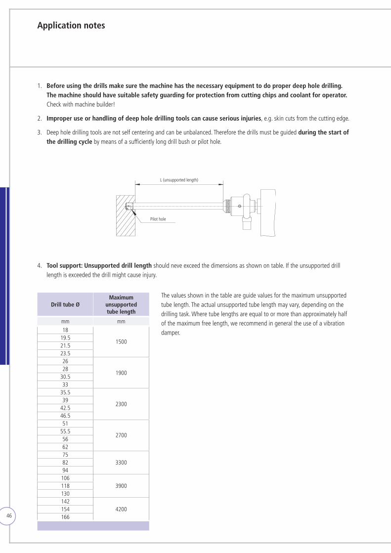
46
Application notes
1. Before using the drills make sure the machine has the necessary equipment to do proper deep hole drilling. The machine should have suitable safety guarding for protection from cutting chips and coolant for operator. Check with machine builder!
2. Improper use or handling of deep hole drilling tools can cause serious injuries, e.g. skin cuts from the cutting edge.
3. Deep hole drilling tools are not self centering and can be unbalanced. Therefore the drills must be guided during the start of the drilling cycle by means of a sufficiently long drill bush or pilot hole.
4. Tool support: Unsupported drill length should neve exceed the dimensions as shown on table. If the unsupported drill length is exceeded the drill might cause injury.
L (unsupported length)
Pilot hole
Drill tube ØMaximum
unsupported tube length
mm mm
18
150019.521.523.526
190028
30.533
35.5
230039
42.546.551
270055.5566275
33008294
1063900118
130142
4200154166
The values shown in the table are guide values for the maximum unsupported tube length. The actual unsupported tube length may vary, depending on the drillingtask.Wheretubelengthsareequaltoormorethanapproximatelyhalf of the maximum free length, we recommend in general the use of a vibration damper.
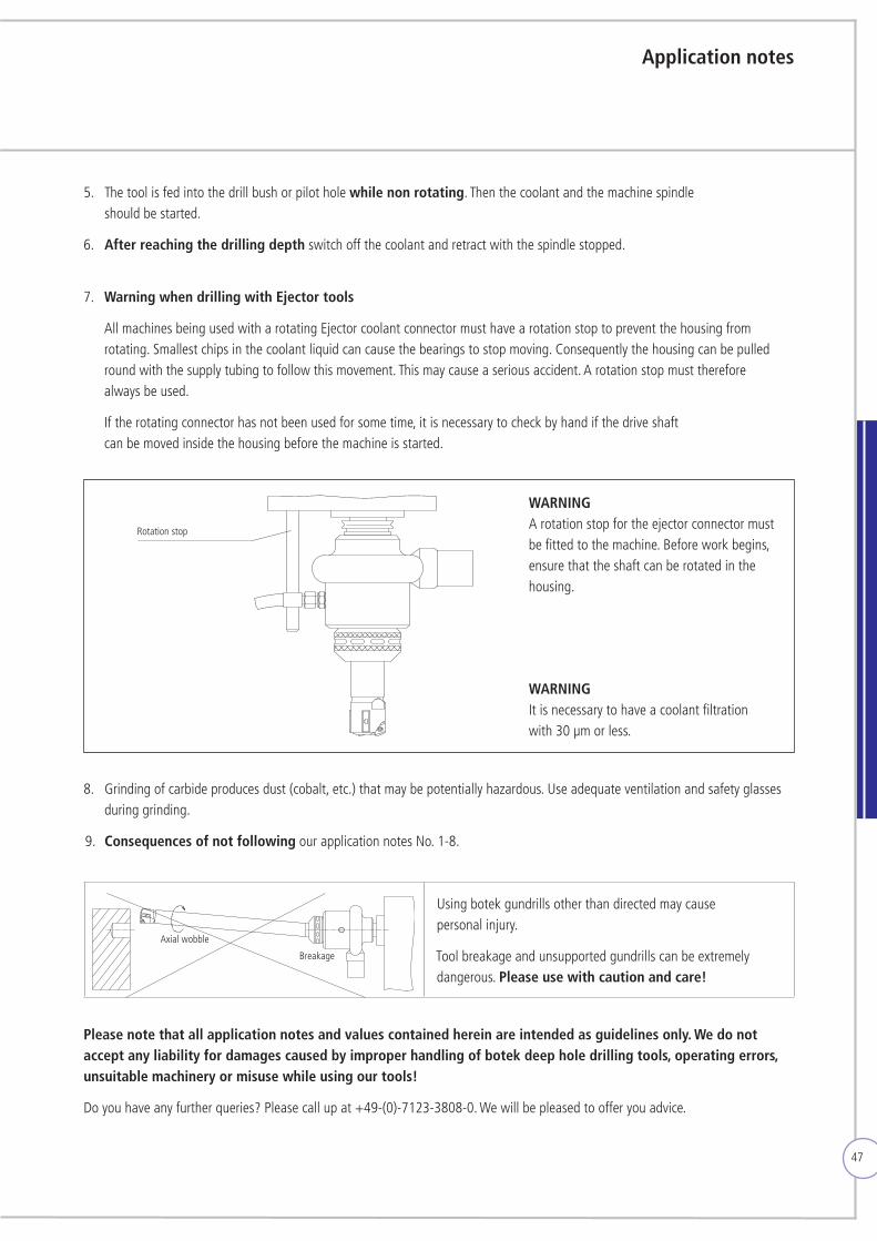
47
Application notes
Please note that all application notes and values contained herein are intended as guidelines only. We do not accept any liability for damages caused by improper handling of botek deep hole drilling tools, operating errors, unsuitable machinery or misuse while using our tools!
Doyouhaveanyfurtherqueries?Pleasecallupat+49-(0)-7123-3808-0.Wewillbepleasedtoofferyouadvice.
8. Grinding of carbide produces dust (cobalt, etc.) that may be potentially hazardous. Use adequate ventilation and safety glasses during grinding.
9. Consequences of not following our application notes No. 1-8.
5. The tool is fed into the drill bush or pilot hole while non rotating. Then the coolant and the machine spindle should be started.
6. After reaching the drilling depth switch off the coolant and retract with the spindle stopped.
7. Warning when drilling with Ejector tools
All machines being used with a rotating Ejector coolant connector must have a rotation stop to prevent the housing from rotating. Smallest chips in the coolant liquid can cause the bearings to stop moving. Consequently the housing can be pulled round with the supply tubing to follow this movement. This may cause a serious accident. A rotation stop must therefore always be used.
If the rotating connector has not been used for some time, it is necessary to check by hand if the drive shaft can be moved inside the housing before the machine is started.
Rotation stop
WARNING A rotation stop for the ejector connector must be fitted to the machine. Before work begins, ensure that the shaft can be rotated in the housing.
Axial wobble
Using botek gundrills other than directed may cause personal injury.
Tool breakage and unsupported gundrills can be extremely dangerous. Please use with caution and care!
Breakage
WARNING It is necessary to have a coolant filtration with 30 µm or less.
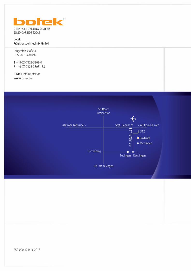
botekPräzisionsbohrtechnik GmbH
Längenfeldstraße 4D-72585 Riederich
T +49-(0)-7123-3808-0F +49-(0)-7123-3808-138
E-Mail [email protected]
Stuttgart intersection
A8 from Karlsruhe » Stgt. Degerloch « A8 from Munich
HerrenbergTübingen Reutlingen
Metzingen
Riederich
A81 from Singen
B27 to Tübingen
B 312
250 000 171/13-2013
DEEP HOLE DRILLING SYSTEMSSOLID CARBIDE TOOLS