DECEMBER - americanradiohistory.com · December 1936 - ELECTRONICS ... of the best known...
68
radio, communication, industria app ca " ons of electron . . engineering an'. manufacture DECEMBER 1936 Price 50 Cents McGRAW-HILL PUBLISHING COMPANY, INC. www.americanradiohistory.com
Transcript of DECEMBER - americanradiohistory.com · December 1936 - ELECTRONICS ... of the best known...
radio, communication, industria app ca " ons of electron . . engineering an'. manufacture
DECEMBER 1936
Price
50 Cents
McGRAW-HILL PUBLISHING
COMPANY, INC.
www.americanradiohistory.com
W
'a' e1/4:
\ \:: Let et / /f e:
L$41\
\-\\\\44, , \, 4
. . ,. _--- M....._ N":«,T.;
_`
METIV C4IRISTMIC
To our good friends in the radio industry
we wish a joyful holiday season and in-
creasing prosperity in the year to come.
STACKPOLE CARBON COMPANY ST. MARYS, PA.
APPY NEW YEAR
www.americanradiohistory.com

ELECTRONICS Adis, communication and industrial applications of electron tnhe. . . design. engineering. manufacture
HOWARD EHRLICH KEITH HENNEY Vice -President Editor
DONALD G. FINK H. W. MATEER Associate Editor Manager
BEVERLY DUDLEY, C. C. FARREY, Assistant Editors
Contents December 1936
COVER: Karl Schumann, glassblower at the Philco Plant, putting the finishing touches on a television camera tube, photographed by S. F. Essig, also of Philco.
Frontispiece 8 Putting Public Address to Work 25 Checking the chassis. Photo by Ken Henderson, Stromberg -Carlson
Radio engineers at Rochester... 9 Reports of the papers delivered at the I.R.E. annual Fall Meeting
Television Advances 14 Photographs of apparatus at NBC, Farnsworth, and Philco
Concentric Line Terminations. .
BY CARL G. DIETSCH Methods of calculating low -impedance termination, circuits
Advanced Amateur Receivers .. 20 BY BEVERLY DUDLEY
Eladio engineering aids amateurs in over -crowded channels
BY H. J. BENNER An all purpose (programs, orders, alarms, etc.) system at the Sickles plant
Three-phase Rectifier Circuits.. 28 BY A. J. MASLIN
.alt that its title implies, and applicable to ignitron uses
16 Automatic Selectivity Control .. 32 BY H. F. MAYER
ASC tube control circuits using feed-back, as Presented at the Rochester I.R.E. Meeting
R -f Impedance of Parallel Lines 35 BY ALFRED E. TEACHMAN
For reference use
DEPARTMENTS
Crosstalk 7 Book Reviews 37 Electron Art 46
Reference Sheet 35 Tubes at Work 39 Manufacturing Review 52
Patents Review 66 Index to Advertisers 64
Index to Volume 9 (January -December 1936 inclusive) 59
Volume 9 . . . Number 11
ELECTRONICS, November 1030. Vol. 9. No. 11. Pub- lished monthly, price 50e a copy. Subscription rates- United States, $5.00 a year. Latin America. $5.00 a year. Canada, $5,00 a year. All other countries. $0.00 a year or 24 shillings, Entered as Second Class matter. August 29, 1930. nt Post Mee, Albany, N. Y under the Act of March 3. 1870.
Branch 011lces: 620 North Michigan Ave., Chicago; 883 Mission St., San Francisco; Aldwych (louse. AldwYch, Iondin, W. C. 2: Washington; Philadelphia; Cleveland: Detroit; St. Louis: Boston; Atlanta. lia.
Contents Copyright. 1030, by McGraw -11111 Publishing Company, Inc.
McGRAW-HILL PUBLISHING COMPANY, INC. Publication Office
DO -120 North Broadway, Albany, N. Y. Editorial and Executive Offices
330 West 42nd Street, New York, N. Y. James H. McGraw. Jr. Malcolm Muir James H. McGraw
Chairman President Honorary Chairman Howard Ehrlich B. R. Putnam D. C. McGraw Vice -President Treasurer Secretary
Cable Address: MCGRAWHILL, New York. Member A.B.P. Member A.B.C.
www.americanradiohistory.com

U. S. Patent Nos. 1,862,486-1,909,476-1,909,477 1,419,564-1,782,387-1,604,122
1,963,800' Other Patents-Patents Pending
Foreign Patents.
EXTERNAL TYPE
INTERNAL TYPE
You're proud of your product. You employ
the finest materials-the most expert workman-
ship. You subject it to exacting inspection to
fact ry serv- insure proper performance
and satisfactory serv-
ice. all this care can be completely s a Shake-
lified
ice. nut or by a single loose connection a of bolt,
Shake -
proof Lockflat orscouniersunk any
yhead-as well as
screw - locking terminals for electrical connections.
No
matter e service, or how severe the vibra -
on Shakep oof's Triple -
Action Lock canall connections permanently
Action to keep but THREE
tight. Shakeproof uciFACTORS ot eStrut-Action,
VITAL LOCKING Initial Line -Bite. Only
Spring-Tension Shakeproof,
w and with its tapered -twisted teeth, can
this positive, vibration -defying, P
give you p
action lock. TEST SHAKEPROOF
'NOW!permanent lock-
ingCheck
our claims fory sending for,FREE Test Ring.
performance bcl
ourself why it provides the Examine the exclusive tapered -twisted tooth
only ipd see for yourself Shakeproof Lock
most searching tests you can only Triple -Action Loc
have been Washersand know why they
devised - thousands of America's Leading Man-
a by for your free test ring today!
ufaccurers.
o w p E R c L OH
EspH
Products Manufactured by Illinois Tool Works
Keeler Avenue, Chicago, Illinois Distributor
o(Shakeprooj Ltd.. Toronto, Ontario
4539 N.
In Canada: Canada Illinois Tools, Copy. 1936 Illinois Tool Works
2
It's the tapered -twisted teeth that lock I
STRUT -ACTION The instant the nut is turned down on a Shakeproof Lock Washer, the tapered -twisted teeth bite into both nut and work surfaces, setting up a sturdy strut -action that pro- vides a powerful leverage against any backward move- ment of the nut.
SPRING -TENSION When the teeth bite in. a pow- erfulspring-tensionisinstant- ly in force. Th is is produced by the exclusive design of the twistedteeth, whichallowsthe body of the washer to resili- ently cooperate in keeping the contact permanently tight.
LINE -BITE The tapered shape of the teeth also assuresasubstantial line - bite at initial contact. As vi- bration increases, this bite becomes deeper, making the locking force even greater.
diriS SHAKEPROO TAPPING SCREWS
with Standard Machine Screw Three
ACTUALLY CUTS ITS OWN THREA
WRIT FOR FREE DEMONSTRATION KI
December 1936 - ELECTRONICS
www.americanradiohistory.com

..
YEARS AGO WE SAID: JkWER RESISTORS COULD BE mADE"...
. ... ...iti'":YP
Initiative - Resourcef ul neue-Cooperation to advance the interests
of the industry
Today - after five years of 'use by a steadily : growing list of the best known manufacturers --IRC Cement Coated Wire Wound Resistors have established records of performance, durability and freedom from faïlurel unexcelled in the power resistance field.
They dissipate heat ' rapidly; have extreme mechanical, strength; are made to stand heavy overloads, moisture-even the famcius salt water immersion test.
Danger of expansion of resistance wire or stress on the wire is definitely eliminated by applying and hardening the famous IRC Cement Coating at comparatively low temperatures.
In short, IRC Power Wire Wounds are designed for those who can't afford to take chances on resistor failure.
INTERNATIONAL RESISTANCE COMPANY 401 NORTH BROAD STREET, PHILADELPHIA, PA.
Factories or Licensees in Canada, England, France, Germany, Italy, Denmark and Australia
MAKERS OF RESISTANCE UNITS OF MORE TYPES, IN MORE SHAPES, FOR MORE APPLICATIONS THAN ANY OTHER MANUFACTURER IN THE WORLD
ELECTRONICS - December 1936 3
www.americanradiohistory.com

PRODUCTION OF SMALL, FINE, SEAMLESS
TUBING IS A PASSION WITH THE MEN WHO ARE THE SUPERIOR TUBE COMPANY OF
NORRISTOWN, PENNA. (25 MILES FROM PHILA- DELPHIA, 100 MILES FROM NEW YORK CITY.)
S. L. GABEL SAYS ---"EVERY MAN IN OUR
GROUP IS AN ASSOCIATE, HE KNOWS TO WHAT USES OUR PRODUCTS ARE TO
BE PUT. PRIDE OF ACHIEVEMENT IS NOT
IN THE MANAGEMENT ONLY - - - IT IS
IN THE SHOP, TOO. OUR BEST SALES- MAN IS THE GOODS THESE MEN PRODUCE.
VISIT OUR PLANT, OUT IN THIS UNUSUAL
SETTING, IF YOU NEED TO BE CONVINCED.
1 December 1936 - ELECTRONICS
www.americanradiohistory.com
W1z HUMIDITY THERE'S LESS EFFECT ON
ERIE INSULATED
RESISTORS
77,77,ACTE3vilNlII79111111R
B UB t,
ONDI I 111111111111W
ERIE I NSULATED RESISTORS /4 WATT %x WATT J , 90% RELATIVE HUMIDITY AT 40*C. ABM». 111111`M iellIMZEI 1111111Kenerjrai .12211:111111 .lg.i M
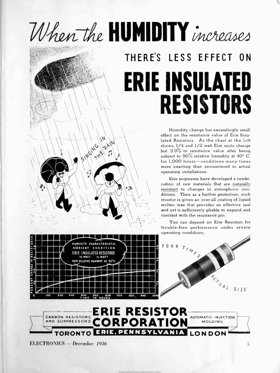
Humidity change has exceedingly small effect on the resistance value of Erie Insu- lated Resistors. As the chart at the left shows, 1/4 and 1/2 watt Erie units change but 3.9% in resistance value after being subject to 90% relative humidity at 40° C. for 1,000 hours-conditions many times more exacting than encountered in actual operating installations.
Erie engineers have developed a combi- nation of raw materials that are naturally resistant to changes in atmospheric con- ditions. Then as a further protection, each resistor is given an over-all coating of liquid molten wax that provides an effective seal and yet is sufficiently pliable to expand and contract with the resistance pin.
You can depend on Erie Resistors for trouble -free performance under severe operating conditions.
RESISTOR ERIE AUTOMATIC INJECTION CARBON RESISTORS
AND SUPPRESSORS CORPORATION MOLDING
ERIE, PENNSYLVANIA LON DON TORONTO ELECTRONICS - December 1936
www.americanradiohistory.com

, . In MALLORY-YAXLEY said -
"In 1936 we will continue the good job-anticipating requirements and making continuous advances"
MALLORY-YAXLEY Present Proof of
Maintained Leadership
During 1936 Mallory -Yaxley introduced the Mallory Precision Vibrator... a development which provided small size, higher con- tact pressure, hair -line precision-and was accorded an enthusi- astic reception by the radio engineering profession generally. During 1936 Mallory-Yaxley announced Yaxley 3100 Type Switches for short wave, tone control and tap applications .. . and opened a new era of small size, compactness, extreme -Circuit flexibility, low capacity and low resistance. During 1936 Mallory-Yaxley offered in the Yaxley line, the most com- plete line of all wave switches ever available - meeting the most exacting demands of the simples or most complicated circuits. During 1936 Mallory -Yaxley presented Mallory Standard Dry Electrolytic Capacitors so designed and constructed to effect immediate, remarkable and wide -spread savings in material cost, production time, and chassis space.
During 1936 Mallory -Yaxley published the first complete author- itative Dry Electrolytic Capacitor Data Book that ever came off a press - nothing was omitted - nothing overlooked.
During 1936 Mallory Grid Bias Cells were used in more receivers by more manufacturers than ever before-further demonstrating the advantages of Mallory-Yaxley engineering in providing su- perior characteristics, advanced design and unusual flexibility. During 1936 Dry Disc Rectifiers produced by Mallory-Yaxley won a greatly increased nation-wide acceptance ... being used in many new applications in which they proved the value of small size, rugged construction, great flexibility and unfailing service.
Mallory -Yaxley success is based on adapting its products to man- ufacturers' specific applications-not simply attempting to sell a static product. Mallory-Yaxley engineers really cooperate.
MALLORYP. R. MALLORY 8. CO. Inc. P. R. MALLORY & Co., Inc. INDIANAPOLIS INDIANA
Cable Address-PELMALLO yiA)mazy
December 1936 - ELECTRONICS
www.americanradiohistory.com

ELECTRONICS DECEMBER
1936
NOBEL PRIZE ... In awarding the Nobel prize in physics to Dr. Carl David Anderson for his discovery of the positron, an event of unusual scien- tific interest was commemorated. The positron is a positive electron. Now it has been pleasant to think of the elec- tron as always negative and although it was a bit annoying to find this elec- tron sometimes acting like a material particle with predictable characteris- tics, and at other times like a wave with true Huygenian qualities, it still was more or less definite, something to hang onto.
Professor Dirac came along and said that there was another of these scien- tific building blocks which resembled an "electrical hole." Dr. Anderson found it on one of the many plates he had exposed; and he found that it had neg- ative energy and other characteristics which are really upsetting to those of us who have sort of settled down to the negative electron.
Our photo, by the way, shows Drs. Millikan and Anderson, the latter a student of the famous measurer of the electron's charge.
OLD STUFF . ... Newspapers again fall for the report that television abroad has reached the point where large pic- tures are thrown on a screen from a very small, very bright cathode ray tube. A lens is used; and the impres- sion is that this is everyday home tele- vision.
This is old' stuff. Demonstrations of this system were made in this country, long ago. One of the engineers who has seen all in Europe states that an f2 lens is used. Now a well corrected 5 cm. lens of this speed costs about $150, which is quite a burden for a tele- vision receiver to assume. And no one will vouchsafe a reasonable life on a cathode ray tube of the brilliance men- tioned in this foreign propaganda.
KEITH HENNEY Editor
Crosstalk TECHNIQUE ... While on this sub-
ject of television, a year-end summary might not be out of place. Demonstra- tions have been held by all those ac- tively engaged in the art, several of them within the last few months. Thus pictures have been seen by technical people, and by the laymen (newspaper reporters) as well. Technical experts are amazed; newspaper reporters are
Drs. Millikan and Anderson, Nobel prize winners 1923 and 1936
blase. And it seems to us that the tele- vision people can learn more from the reporters than from engineers.
Reporters state that the first demon stration (no matter who made it) was the best; thereafter it becomes a mat» ter of the show. What did they see? Therefore if the camera man, or the fellow manipulating the lights or the monitor engineer does not handle his end of the pick-up properly, the show is no good. If there is bad distortion due to faulty camera work, or bad
electron beam control, or if a shaft of light gets into the lens (like pointing your camera at the sun) the reporter feels that the art has not progressed.
Will the green and black images sat- isfy the purchaser? Will 441 lines spread over 8 by 10 inches make him feel his $500 has been well spent? It depends upon those who stage and con- trol the show. For example the Philco demonstration was fair enough, but in retrospect rather dull until Boake Car- ter finished his message and then look- ing into the lens suggested that someone at Chief Engineer Grimditch's house give him a ring on the 'phone. Mr. Carter recognized the voice at our end of the wire, and in the give and take of the ensuing conversation the whole show took on life - we lost contact with radio and television - we were in on something intrinsically entertaining.
The fire department scene at Camden and certain portions of the NBC dem- onstration emphasize that a program of surpassing interest is gding to be neces- sary to separate the looker -in from the cold fact that he is looking at a rather small tinted picture which gets to him by methods he can appreciate.
At present the trade need not feel that television sets are imminent enough to steal the market away from a good radio. And the engineers need not worry that their work is done - there must be a lot of improvement be- fore the big market is ready for these new luxuries of the electron. And these improvements will have to be carved out of very solid rock, in our estimation.
CHASTENED ... Called for not in- cluding Hygrade Sylvania among those tube companies which issue technical bulletins, we hasten to admit that we have read and learned from "Modula- tion Capabilities of Infinite Impedance Detectors" and "Input Capacitances of Tubes at Audio Frequencies" to men- tion only two of the recent papers.
www.americanradiohistory.com

CHECK!
Here is es crything necessary for checking a radio receiver chassis base except the checker. Apparent. ly called away from his work, he left it for the photographer - Ken Henderson of Stromberg Carlson Telephone Manufacturing Company
www.americanradiohistory.com

Radio Engineers Look Ahead
Record attendance at Fall meeting hears papers on television, automatic selectivity control,
noise limiting circuits, loud speaker measurements and improvements, allocation problems,
etc. A review of the Rochester papers
WITH a total registration of 450, nearly one hundred more
than in 1935, the annual Fall Meet- ing of the I.R.E. came to a close on November 18th with its reputation for interesting papers and argu- mentative discussions well preserved. The fifteen papers presented were aimed primarily at radio -set engi- neers, according to the usual custom at Rochester meetings. Among the topics discussed were: loudspeaker and other acoustic problems with special reference to the use of laby- rinths and similar acoustic networks ;
television from the commercial, tech- nical and regulatory points of view; radio circuits including feed-back amplifiers, high frequency receiv- ers, and highly interesting systems for controlling selectivity automat- ically; u -h -f current measurements, shot -effect tube noise; and general papers on radio tubes, the FCC, and on the relation of receiver charac- teristics to station allocation.
The convention program included also the annual Rochester Banquet and a trip to view the cyclotron (atomic bombarder) at the Univer- sity of Rochester. A large number of manufacturers' exhibits were on dis- play. These exhibits contained many of the newer types of radio components and testing equipment. One concern showed the action of a power -supply vibrator by viewing it under stroboscopic light; another the use of a cathode ray oscillo - graph for measuring pressure in conjunction ' with a piezo-electric pick-up ; another demonstrated trans- mission and reception of supersonic waves.
The following report of the con- vention papers has been prepared by the editors from notes taken in the technical sessions. Some of the pa- pers may be reported in full in the Proceedings of the I.R.E. and others
will be found in Electronics in later issues. H. F. Mayer's paper, for example, on automatic selectivity control is presented elsewhere in this issue.
Loudspeaker Acoustics and Measurements
The meeting opened with a paper by S. V. Perry of RCA Victor on "Equipment and Methods used in Routine Measurements of Loud Speaker Response". Mr. Perry re- viewed briefly the progress in this work from the manual methods of reading loudspeaker response, through the semi -automatic methods (see Frontispiece, Electronics, No- vember 1936), to the fully auto- matic method in which a beam of light traces the pressure -response curve photographically. To obtain consistent results, the effect of standing waves produced by the loudspeaker in the room must be re- duced. This may be done by plac- ing the pick-up microphone close to the loudspeaker, by moving the mi- crophone through the standing wave, or by varying the frequency im- pressed on the speaker (warble -tone method). Of these the first two were described. The close-up meth- od is used in measuring the char- acteristics of individual loudspeak- ers; the moving microphone method for measuring loudspeakers mounted in receiver cabinets.
RCA uses two types of micro- phones for pick-up work. One is a specially constructed shallow -cavity condenser microphone (whose pre- amplifier uses an acorn triode, thus greatly reducing the size of the as- sembly) . This condenser unit is used for all frequencies from the extreme lows up to about 10,000 cps, but not higher. The other is a special rib- bon -velocity microphone having an electro -magnet field, which is not
used below 100 cps, but which goes on up to about 20,000. Each micro- phone has its associated compen- sated amplifier.
In checking the speakers, the voice coil is fed with about 0.1 volt-am- peres, which is approximately normal use for the home. The impedance of the voice coil is measured under these conditions by a substitution method, over the frequency range. The nominal impedance is that value existing, usually near 400 cycles, where the impedance does not change markedly with frequency. It was pointed out that pressure response curves are principally valuable for comparing speakers measured under the same conditions, but do not indi- cate absolute performance.
U -h -f Current Measurements
John Miller of the Weston Electri- cal Instrument Corporation present- ed a paper on "Current Measure- ments at Ultra -high Frequencies." He pointed out that while the ther- mal meters are universally used for high frequency measurement, the hot-wire type has become nearly ob- solete because ambient temperature compensations are so difficult. The thermocouple type of meter, how- ever, may be properly compensated. When it is desired to calibrate such meters at 100 Mc., however, there is no standard ammeter available for comparison purposes. It is known that thermocouple meters read high at high frequencies, since the skin effect then produces more heat in the heater element per unit of current through it. For the same reading on the meter scale, however, the heating must be the same, hence
and: l',tr,r = ! hfrht
Iht = I,t\/r,t/rht The high frequency current can be found from the accurately measur-
ELECTRONICS - Decembér 1936 9
www.americanradiohistory.com
able low -frequency current, there- fore, if the ratio of the low -fre- quency resistance to high frequency resistance is known or can be calcu- lated. In a typical thermocouple meter (11 mil heater wire) this lat- ter ratio at 100 Mc. is 1/2.57, giving an error of about 36 per cent at that frequency. To reduce the er- ror, it is first necessary to get a fairly reliable comparator. This was done by the use of tungsten - filament lamps whose filaments were of small diameter (hence less affected by skin -effect) so that the ratio of resistances was only 1/1.065 Mc. at 100 Mc. giving an error of only 2 or 3 per cent. The tungsten lamps were fed several amperes of current from an 80 Mc. oscillator and their temperature determined by a photo- electric photometer. The same pro- cedure was repeated at 60 cycles. In terms of these data the thermocouple meters were checked and the errors found plotted for convenient correc- tion of the calibration.
To reduce the errors of the ther- mocouple a new type of heater ele- ment consisting of thin -walled plat- inum -iridium tubing was used, this configuration confining the current to the same path regardless of the fre- quency. The error found in these thermocouples (in terms of the tung- sten lamp "standards") was about 3 to 5 per cent at 100 Mc. as against 50 to 70 per cent error at the same frequency for conventional couples. Further accuracy was deemed unnec- essary in view of the other factors which obtain in present-day measure- ments at ultra -high frequencies.
Cabinets and Loudspeaker "Lows"
The currently popular topic of acoustic networks in radio receiver cabinets was discussed in a paper by Hugh Knowles, chief engineer of the Jensen Radio Manufacturing Com- pany. Mr. Knowles began his paper with a mathematical tour de force into the "double source" problem in acoustics, for 'example the effect on the sound pressure resulting from radiation both from the front and the rear of the cabinet, or from the loudspeaker and an auxiliary acoustic network (labyrinth, series of ports, openings, etc.)
By means of electrical analogs to the acoustic conditions, he showed that the effect of the second source on the reproduction depended not
10
only on phase relations, but to a considerable degree upon the dissipa- tion in the secondary network. For example, a simple acoustic pipe or conduit can be represented electri- cally by a transmission line with dis- tributed inductance, capacity and re- sistance. The terminations (short circuit, open circuit, etc.) of the transmission line correspond to an open ended pipe, a rigidly closed pipe, a pipe terminated in an auxiliary diaphragm; etc. In particular if a cabinet with a solidly closed back can be filled with a sufficient ab- sorbing material a considerable strengthening of low frequency re- sponse will result. The rear of the cabinet may be only partially closed, with open ports which serve both acoustically and thermally, since ventilation of the chassis is usually necessary. A port may also be used in the front of the cabinet, and if used in connection with an auxiliary acoustic circuit (containing consid- erable dissipation), the low fre- quency response is still further im- proved. In general Mr. Knowles showed that all the cabinet bass - boosters being used by radio manu- facturers derive from the same theory, but that they do not all per- form in identical fashion, of course, because of the different arrange- ments used, particularly in relation to dissipative elements.
B. J. Thompson and D. O. North of RCA Radiotron prepared a paper
on "Shot -effect Noise in Space - charge -limited Vacuum Tubes." Mr. Thompson, who presented the paper, introduced the subject by saying that tube noise, relatively unimpor- tant in present-day receivers, will undoubtedly play a major role in the design of television receivers and other wide -band equipment. The essence of the paper was a new point of view with regard to the mech- anism of shot -effect, an experimental confirmation of the theory, and an indication of the way in which noise may be reduced in positive -grid (screen -grid pentode) tubes.
When all emitted electrons are re- moved at once and no space -charge forms in the cathode -anode inter - space noise components in the cath- ode current are to be expected from the random emission of electrons, which within a very small space of time will be larger or smaller than in another space of time. If the emission is then limited by space charge, the noise component decreases, until at complete space charge no electrons are removed and the noise component should be zero. At intermediate values of space charge, (according to the Thompson -North view) the noise value is the result of the fol- lowing circumstances : the potential minimum (due to finite initial vel- ocity) in the cathode -anode space becomes the surface of a "virtual cathode," which then operates like an ordinary cathode under temper -
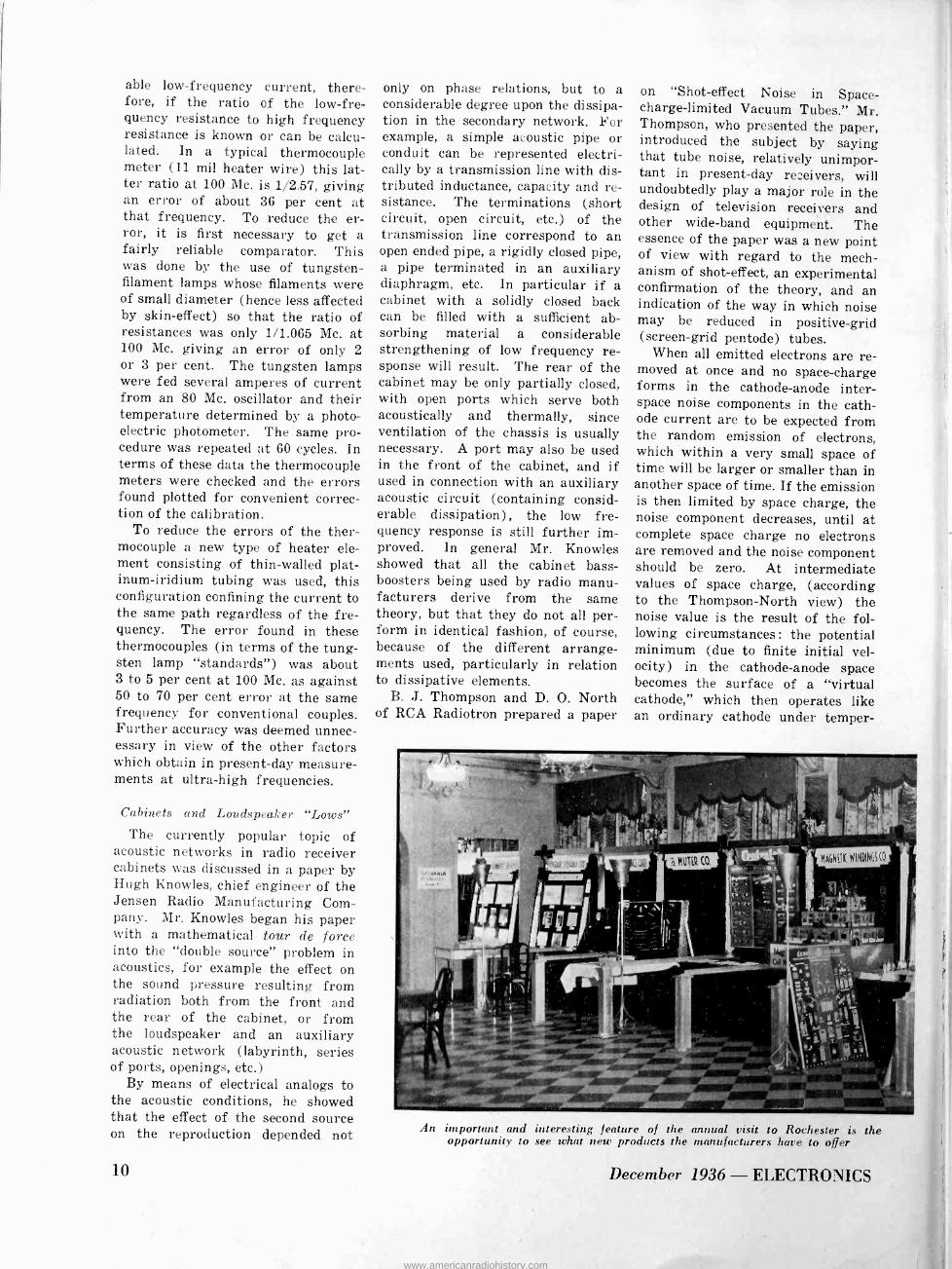
An important and interesting feature of the annual visit to Rochester is the opportunity to see what new products the manufacturers have to offer
December 1936 - ELECTRONICS
www.americanradiohistory.com

ature-limited conditions. If we apply the thermal noise formula (used for temperature -limited noise) to this ease, the correct result should be ob- tained if a factor of 0.6 is used as a multiplier. This has been checked experimentally, the values of the factor ranging from 0.6 to 0.8. The actual mechanism of the effect is pictured as follows : at the potential minimum the space charge varies in a random fashion due to the random emission of electrons. At a certain small element of surface in the virtual cathode a small increase of current may occur, but this is com- pensated by an equal current flow of electrons back to the emitter, which, however, takes place over a much larger area surrounding the small element in question.
In tubes containing a positive grid the noise in the plate circuit is much larger than that contributed by the cathode. This extra noise comes from the random distribution of current between the screen grid and the plate. If the screen current can be reduced, then the variations are reduced in proportion, and the total plate circuit noise approaches that contributed by the cathode alone. It appears possible by reduc- ing the screen current by suitable design that the noise present may be reduced to about one-half of its present value.
Commander T. A. M. Craven, Chief Engineer of the FCC outlined
:oiNR1 MUIER CORP.
the necessity of coordinated work be- tween the Commission, the IRE and RMA Engineering Division. He made clear to the engineers that allocation solutions were always com- promises of some sort. For example if the broadcast stations are allocated frequencies according to the highest selectivity of modern receivers, audio fidelity would suffer. Equal disad- vantages, but in other directions, would occur if stations were placed in the spectrum according to re- ceivers of the lowest selectivity. Commander Craven paid high com- pliments to the engineering division of RMA for their cooperation in the recent meetings to discover facts which would be useful in future al- location and power problems. There were still questions, however, on which the Commission needed infor- mation of the type that engineers could give.
For example what is the desired ratio between wanted and unwanted signals, 10 kc. apart? The second problem on which light is wanted, is that of blanketing. Engineers state that modern sets are not blanketed on a 1 -volt input. And yet the Com- mission gets complaints from locali- ties where the inputs are of the order of one-half this figure.
The third problem is that of the intermediate frequency used in superheterodynes. If proper coordi- ination had taken place some time ago it is probable, according to Mr.
S T JFAKOF F LABORATORIES
This year, over 30 manufacturers took space at the Fall meeting, providing a profitable trade show of the components and raw materials manufacturers
ELECTRONICS - December 1936
Craven, that an international agree- ment could have been reached setting aside a frequency for no other pur- pose than for i -f amplifier use. But the trouble is that the set manufac- turers themselves are not agreed as to the frequency they want. Before this problem is properly settled in this country the various government departments which have radio serv- ices will have to be brought into the picture. It is in this kind of situa- tion where the engineers in the pro- fession can be most useful.
On transmitter problems, the FCC must look to the IRE because of the lack of an organization among manu- facturers of this type of apparatus corresponding to the RMA engineer- ing committees.
Radio Tubes Today
Four topics of vital interest to the industry concerned with receiving sets and tubes were discussed by Roger Wise, chief radio engineer of Hygrade Sylvania. First he dis- cussed the position of the tube manu- facturer in the industry, comment- ing on the very high mortality among tube makers since the early days. It is worth noting that there is less concentration of manufacturing now than in the days when there were ten times as many tube plants.
Mr. Wise spoke of the indigestion of the industry caused by the metal tube and of the present diversity of types of tube. In his plant a survey showed that only a few tribes ac- counted for the greater proportion of production. For example the 78
and 6K7G accounted for 17.6 per cent of the total production for the first 9 months of this year. The 6A7 and 6A8G accounted for 11.3
per cent. Overall, thirty-seven types made up 75 per cent and the re- mainder of production was made of 78 different tubes. The greater pro- portion of production should com- prise about 16 tubes if the present trend toward octal bases continues.
Out of 52 new type numbers assigned in 1936, 8 were ballast tubes. Of the remaining 44, only 16
were actually new tubes from the tube maker's standpoint. The others presented no problems, being merely new bases on old tubes, changes in heater current or other slight modi- fications.
On the question of parameter
11
www.americanradiohistory.com
limits, Mr. Wise pointed out that tubes were now remarkably uniform considering the complexity of struc- ture and the many chances for varia- tion. He showed curves of great in- terest prepared by Marcus Acheson showing the effect on parameters of slightly displacing the grid from its optimum position in the cathode - anode field.
Problems still existing are those relating to the proper use of the tubes, the set manufacturer often taking into his own hands the maxi- mum voltages and currents at which the tubes were to operate, usually in excess of the limits set by the maker of the tube. The situation of rectifiers is particularly severe be- cause of the occasional breakdown, or deforming, of the first filter con- denser. Such breakdown, by causing the plate to emit, sends high-speed electrons to the cathode because of the high voltage existing across the tube under this condition.
Acoustical Labyrinth B. J. Olney of Stromberg -Carlson
presented new experimental data on the acoustical labyrinth, which was first demonstrated before the Rochester meeting two years ago. He likened the acoustic network of the labyrinth to the electrical analog of the "leaky" telephone line, and showed the peaks of mechanical im- pedance which occur in such a sys- tem. The labyrinth is lined with large amounts of sound -dissipating material; such materials have the property of selective absorption and in general attenuate the high fre- quencies much more than the lows. The network thus acts as an efficient low frequency resonator but is highly inefficient in the high fre- quency region. Confining his meas- urements to frequencies below 1000 cycles, Mr. Olney showed how the system extends the low frequency re- sponse and at the same time presents a sharp low -frequency cut-off below the desired region. By its use the resistance component of the air column against which the speaker acts is greatly increased over the value offered to a piston operating in an infinite baffle, and this in- creased resistance has the effect of increasing greatly the low -frequency radiated power. In addition it has the effect of reflecting a high re- sistive component through the out -
12
5
0
5
10 2 o 15;:t»
20 ° 25 i 30 'La.
35 m
40
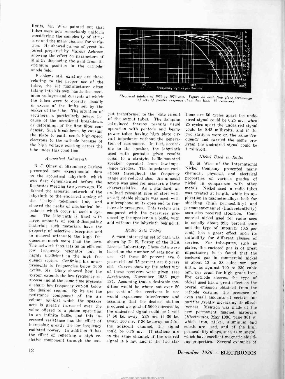
Electrical fidelity of 1935 to 1936 sets. Figure on each line gives percentage of sets of greater response than that tine. 83 receivers
put transformer to the plate circuit of the output tubes. The damping introduced thereby permits usual operation with pentode and beam - power tubes having high plate cir- cuit impedance without the genera- tion of resonances. In fact, accord- ing to the speaker, the labyrinth used with pentodes gives results equal to a straight baffle -mounted speaker operated from low -impe- dance triodes. The impedance vari- ations throughout the frequency range are reduced also. An unusual set-up was used for measuring these characteristics. As a standard, an un -lined resonant pipe of steel with an adjustable plunger was used, with a microphone at its open end to reg- ister air pressures. This system was compared with the pressures pro- duced by the speaker in a baffle, with and without the labyrinth behind it.
Radio Sets Today
A most interesting set of data was shown by D. E. Foster of the RCA License Laboratory. These data were based on the number of sets now in use. Of these 50 percent are 3 years old and 75 percent are 5 years old. Curves showing the selectivity of these receivers were given (see Electronics, November 1936 page 13) . Assuming that a desirable con- dition would be where not over 20 per cent of the receivers in use would experience interference and assuming that the desired station produced a signal of 5000 microvolts, the undesired signal could be 1 volt if 50 kc. away; 225 mv. if 30 kc. away; 100 mv. if 20 kc away, and for the adjacent channel, the signal could be 6.75 mv. If stations are on the same channel, if the desired signal is 5 mv. and if the two sta-
tions are 50 cycles apart the unde- sired signal could be 0.25 mv., when 25 cycles apart the undesired signal could be 0.42 millivolts, and if the two stations were on the same fre- quency and carried the same pro- gram the undesired signal could be 1 millivolt.
Nickel Used in Radio E. M. Wise of the International
Nickel Company presented many chemical, physical, and electrical properties of various grades of nickel in comparison with other metals. Nickel used in radio tubes was treated at length, while its ap- plication in magnetic alloys, both for shielding (high permeability) and permanent -magnet (high retentivity) uses also received attention. Com- mercial nickel used for radio uses is usually about 99.5 percent pure and the type of impurity (0.5 per cent) has a great effect upon its suitability for different classes of service. For tube -parts, such as plates, the enclosed gas is of great importance; it is found that the enclosed gas in commercial nickel is about 13 to 28 cubic mm. per gram, as against 100 to 230 cubic mm. per gram for high grade iron. For cathode sleeves, the type of nickel used has a great effect on the overall emission obtained from the cathode coating, the presence of even small amounts of certain im- purities greatly increasing itQ effect- iveness. Mention was made of the new permanent magnet materials (Electronics, May 1936, page 30) in which iron, nickel, aluminum and cobalt are used, and of the high permeability alloys, such as mumetal, which have excellent magnetic shield- ing properties. Several examples of
December 1936 - ELECTRONICS
www.americanradiohistory.com

1
1.2
1.1
1.0 100
0.9 90 a 0.8 80
d 0.7 70 + 20.6 d 60
0.5 L50 04 á 40
0.3 30
0.2 20
0.1 10
O 00
(2)
(4) -1
2) 3) --j- (4)
(3) i
.
Curves (I)and(I)'Fideli+yand Delay for 6.9 MC. Carrier (rL) u(2y ir ni u n 6.4 u II
(1) ,, (3) 1, (31 1, ir 6.2 1,
u (4) a (t¡. n n n 5.6 u n
43
.
0.2 0.4 0.6 0.8 1.0 1.2 1.4 1.6 Frequency in Megacycles
- 1.8
`4)
2.0 2.2
Fidelity and delay characteristics of single-sideband television reception
British cathode -ray -gun shields made of similar material were shown. The use of nickel iron alloys as trans- former core material has resulted in extremely small high-fidelity units which weigh only a few ounces, widely used in portable applications.
Television on Suppressed Sidebands A highly interesting development
in television was outlined by D. W. Epstein of the RCA Manufacturing Co., who presented the paper "Side - band Suppression in Television Re- ception," written by Mr. Epstein and Mr. W. J. Poch. It was found in experimenting with television re- ceivers that a better image often re- sulted if the circuit was tuned to one side or the other of the carrier, resulting in a partial suppression of one of the sidebands. The increased detail obtainable under this condi- tion was explained in this manner : The bandwidth passed by the re- ceiver was narrower than that trans- mitted. By detuning, more "highs" were accepted by the receiver, at the expense of signal strength, re- sulting in a more detailed image with a lower signal-to-noise ratio. Such detuning retained double side -band reception on the low (overall scan- ning line) frequencies, which were proportionately stronger than the highs. If the receiver band -width is widened in the attempt to accept both transmitted side -bands fully (with on -carrier tuning), the gain per stage decreases in direct propor- tion to the band -width, necessitating more stages. Hence to make the most economical use of the band -width available at the receiver, single side - band transmission is highly desir-
able. Likewise the space thus made available in the television band can be put to use by decreasing the width of guard bands, etc.
Messrs. Poch and Epstein ex- amined theoretically and experi- mentally the effect of single side - band reception on frequency (fidel- ity) and phase response. The re- sults are shown in the figure. Curve (3) (for a 6.2 Mc. carrier) shows very desirable characteristics. The transmitter and receiver in the ex- perimental set-up were equipped with rejector circuits which lowered the energy transfer in the lower fre- quency side -band. Among other things it was found that distortion in the second (linear) detector cir- cuit under these conditions did not become serious up to the maximum modulation level of the transmitter (about 80 per cent). Wave -form distortion in a television image due to the presence of second and third harmonics seems, in fact, to be less serious than it is in audible repro- duction.
It appears probable that further research along these lines may ma- terially alter the present concepts now current on television -band di- mensions, since in the ideal case a given picture can be sent in half the band -width used for the usual double - side -band method.
Television Standards Reviewed
A. F. Murray, Acting Chairman of the RMA Committee on Television Standards, reviewed the recommen- dations which the RMA made to the FCC at the u -h -f hearings last June. These recommendations were re- ported in the July 1936 issue of
ELECTRONICS - December 1936
Electronics (page 9) : they are briefly as follows: A band from 42 to 90 Mc., consisting of television channels each 6 Mc. wide including suitable guard bands; the sound car- rier to be higher in frequency than the visual carrier within each chan- nel; negative transmission (decrease in light increases radiated power) ;
a 441 line picture, scanned completely 30 times per second, with a two -to - one interlaced pattern giving 60 field scannings per second; an aspect ratio of 4 -to -3; and at least 20 percent of maximum amplitude devoted to syn- chronizing pulses.
Mr. Murray gave complete expla- nations of the reasons why each standard was decided upon, and asked that the RMA and the IRE stand behind the committee in sup- porting the recommendations. He pointed out that the standards were formulated with the possibility of single-sideband transmission in mind, and asked those present to give thought to the problem of designing a powerful transmitter for this mode of operation. As pointed out by Mr. Epstein in his paper (reported be- low), single - side - band operation would permit a much more econom- ical use of the band -width available in the receiver, while at the same time permitting more stations to occupy space in the television band.
Dr. Goldsmith Analyzes Television's Needs
Dr. Alfred N. Goldsmith, whose consulting practice both in radio and sound motion pictures gives him a very broad view of the field, pre- sented "Commercial Television and Its Needs." He outlined six main re- quirements for successful television : 1. A cooperative and progressive attitude on the part of the govern- ment in regulating the art ; 2. A sufficient number of television broad- cast stations; 3. A program -building organization which can provide inter- esting material; 4. Sound engineer- ing and manufacturing methods for the production of receivers ; 5. A group of home -lookers to view and appreciate the programs provided; 6. Advertisers to support the service through the sponsorship of pro- grams. He emphasized the program - cost -per -listener which, he said, "is the Sphinx at which every broad- caster thoughtfully stares, awaiting
[Continued on page 36]
13
www.americanradiohistory.com

Television at Hand
December 1936 - ELECTRONICS
www.americanradiohistory.com

1
2
3
4
5
6
Studio-Lights and cameras are now added to the stage properties of broadcasting.
Technique is changed accordingly. Scene made in Farnsworth television laboratories
Tubes-Water-cooled, high -frequency amplifiers in Empire State building where
National Broadcasting Company television field experiments transmissions take the air
Control-Bays of control panels for monitoring video (sight) and audio (sound)
channels for three cameras at experimental laboratories of Farnsworth, Philadelphia
Transmitter-NBC Empire State transmitting equipment a quarter -mile above street. Sig-
nals arrive by concentric cable from Radio City, go to antenna through concentric line
Receivers-Views of Philco television receivers. The purchaser buys much equipment,
sees his picture in a mirror upon which is reflected the actual cathode-ray tube image
Oscillators-At Philadelphia, station W3XE, which is the Philco transmitter, operates
on 51 megacycles. The organ -pipe assemblage is the 846 -tube oscillator, water -cooed
ELECTRONICS - December 1936
www.americanradiohistory.com

Terminating Concentric Lines The theory and practice of coupling the newly popular low -impedance concentric trans- mission lines to antennas of various characteristics, for maximum reliability and efficiency
HE use of transmission lines, especially those of the concentric
tube or coaxial type, affords a con- venient and efficient means for con- veying radio frequency power. An important element to be considered in the design of such a line, whether it is to convey the power output of a transmitter to its antenna or from one stage to another of any radio frequency system, is the line termi- nation of the circuit. Best results, insofar as reliability and efficiency are concerned, are secured when the termination circuit presents to the output end of the line an impedance equivalent to the characteristic im- pedance of the line. This impedance, being for all practical purposes equal to VL/C, resembles a real quantity in the form of an effective resistance equal to Z0. Unless the line "looks into" an equivalent impedance to Z.,
By CARL G. DIETSCH National Broadcasting Co.
stationary waves will form along the line, provided that the length of the line is long compared with the wave- length of the power being transferred as in the case of a line feeding power to an antenna. As a result of these standing waves, high potentials exist across the line in the vicinity of the voltage anti -nodes, which tend to break down the insulation at these points. Although the shielding of a concentric line usually prevents radi- ation from these waves, the presence of voltage and current anti -nodes tends to produce rather serious di- electric and conductor losses and to prevent a most efficient transfer of power.
Cases (4) and (2\
X3 r \ x2=0 60
_i - -T- Z --3" X, RA :;
. . }
Case I
Case (3)
Z0 --I>
X3 0001) \ Lc
X2
X,r-R^f C ase 2-a
X3
(TO ,, X ,,Z; CA Zo XT RA`.
1 >
C ase 2-b
rj
X3 -J oaoó'
X3 X4 X2
--;r-, u <
RA XT Antenna capacitive
Lc X
XTGB
X3 CI -00Th
xT
ZA
''»R
--
4
i XI------ x2 - ï
RA
_r
Antenna inductive
Fig. 1. Connection diagrams and equivalent circuits for terminating .con- centric lines when antenna is reactive or non -reactive
]6
In a previous paper', information is given concerning transmission line terminations for the condition where the characteristic impedance of the transmission line is greater than the resistance of the antenna circuit. The reader is referred to this paper for the treatment of this case, and for the simple case where the antenna resistance and characteristic imped- ance are equal (Z. = RA) .
The growing use of concentric lines of the low -impedance type, how- ever, has led to cases where the char- acteristic impedance of the transmis- sion line is lower than that of the antenna resistance. It is with these cases that the present paper is con- cerned. In general there are three cases to consider: (1) when the antenna impedance contains a resist- ance component only; (2) when the antenna impedance contains a resist- ance component and a reactive com- ponent, either capacitive (2-a) or inductive (2-b) ; and (3) when the antenna impedance contains resistive and reactive components, the latter being partially compensated by the insertion of an extra reactance of opposite sign. These three cases are considered in order.
Case (1)-Antenna Impedance Purely Resistive
Refer to Fig. 1. The concentric line, characteristic impedance Z0, is terminated by a network consisting of CB, Lc, and the antenna impedance ZA. For case (1) the reactance of the antenna impedance is zero, and Zo<ZA = RA. Then the complex im- pedance Zl, presented to the end of the transmission line is :
Z = RA[ X3 X, -X1( X3-X1)1+j [ Xa X12+RA (XS- Xl)]
RA2 +. X12
(1)
where RA, X1 and X, are as given in Fig. 1. For proper termination Z.
1. "Antenna terminations" Carl G. Dietsch. Electronics, Sept. 1935.
December 1936 - ELECTRONICS
www.americanradiohistory.com

E S O
140 L J º
Ë
100 a
m Q E
+ N
CIO
60 6
120
80
Inductive Reactance X, Ohms 0 SO 100 150 200 250 300 350 400
¡ i
1 I -1 1
II
3
0
IZ/IPMA/E: 1 ///!i/h
IBM /ARIER I I tim
I
3
AIR
I
Dotted curves -- Solid curves
-- -- values of X 3 values of X1
25 50 15 100 125 150 175 200 225 250 275 300 325 350 375 400 425 450
Capacitive Reactance X, of Capacitor CB
must equal ZL, hence Z,, must be real, and the imaginary term is zero. Then Z,, = Z. becomes:
RA X12 Z,
RA2 + X12
from which X1, the reactance of con- denser CB, becomes:
X1= RA
(2)
(3)
and X, (calculated by equating the j -term to zero), the reactance of in- ductance Lc, is:
RA2X1 Xs X12 + RA2
Since CB = 1/(2,rfX1) and L.= Xa/ (2af), their values in microfarads and microhenries are then readily cal- culable from f, the frequency of oper- ation. Figure 2 gives various values of X1 and Xa in terms of values of Zo and RA.
Case (2-a) - Antenna Impedance with Capacitive Reactance
Refer again to Fig. 1. It will be noted that the equivalent diagram for Case (2-a) is the same as case (1) , except that the antenna imped- ance is now Z1 = RA - jX,. In this case the complex impedance Z,, pre- sented to the concentric line is:
RA X12 -I- j(RA2(Xa-Xi) + Xs X22 + 2
ZL = R42 + (X2
X1 X2 X3 + XaX,2 - X22 X, -X2 X12)
+ X,)2 (5)
If the line is to be terminated by a real impedance equal to Z0, the im- aginary part of this equation must be zero, as in case (1) . Then Z,. =
Zo becomes :
RA X1' Z0_ RA2 +(X2+ X;).
(6)
from which:
Xl RA Zozo
X2±4 RA(R42+X22-Z,RA) / 0
(7)
Also, equating the imaginary term to zero, as before:
Xl(RA2 + X2X1 + X22)
X a RA2 + ( X1 -i- X2)2 (8)
fig. 2. Values of terminating re- actors for Case (1)
Hence, with Z0, RA, and X, given, X, and X. can be calculated by the above equations. From the values of X, and X,, L0 and CB can be calculated, exactly as in Case (1). Values of X, and X3 for various values of RA
and X2, for the cases where Z. is 80 and 100 ohms are given in Fig. 3.
Case (2-b) - Antenna Impedance In- ductively Reactive
Reference to Fig. 1 for case (2-b) shows that it is the same as Case (1) except that ZA = RA -{- jX2. By a sim- ilar process to that used for Case (2-a) we obtain formulas for X, and
Xa as follows: Zo
X1 RA X,± /vZo (RA2+ X22-Z°RA)
S
(9)
and: Xl(RA2+ X22 - X2 X1)
Xs- (10) RA2 + (X, - X,)2
from which Lc and C8 are calculated
Fig. 3. Values of terminating re- actors for Case (2-a)
650
600 E s 0 550 ç
s 500
+ 450 ú
Ú 400
o 350 U C
ÿ 250 a
300
X 200
3 ase (21a) ¡ r - -Z 0= 100 ohms - Zo = 80 ohms -
d
p.00 03
'e-;V-ßP_%',gP -->) 60 0
ßP 400 9.>>.
-RA= 600"'
4 // --dRA- 800w
-_ï- RA=400w
.=200`''
50 100 1501,200 250 300 350 400 450 500 X2= Capacitive Reac+once of Antenna in Ohms
U -.1
U C 6
400 d a
>
200 0 a
100 Ç 1
M X
300
www.americanradiohistory.com

500
as in the previous cases. Figure 4 shows various values of X, and X. in terms of RA and X2, for Z. values of 80 and 100 ohms.
Case (3) - Added Reactance to An- tenna Impedance
When the transmission line imped- ance "looks into" a complex antenna impedance, it is possible to simplify the adjustment of the circuit greatly by adding a reactance X, as shown in Fig. 1 for Case (3) . This reactance X, may be either inductive or capaci- tive, as shown. If the sum of Xi and X. is inductive, then X. is made capacitive and vice versa. The value of X, is such that the algebraic sum of X1, X. and X, is equal to zero. Since X, is in series with the antenna impedance, it adds directly with the reactive part of the antenna imped- ance. The effect of the presence of X, can then be taken into account by applying the formulas of case (2-a) or (2-b). It is found by so doing that the values for both X, and X. are expressed by a very simple equa- tion :
X, = X. = 1ZR (11)
This occurs only, however, if X, is so chosen that:
f X, - XL F X2 = 0 (12)
The reactance X, must always have the opposite sign from X2, as indi- cated by the plus -or -minus signs in the equation. When X, is so chosen, the reactance X1 and X. may be ob -
m400 u
+ 350 i.;
á 300 U
o
e 250 u L a
ú 200 a d
150 X
a 450 E
L C
-t -'óöòo o Z } X3
CB
X
X2
. ZA. Rg+ X2
o
Case (2-b
KEY A X1 (20=80 Ohms) --- X 3 (Zor 80 Ohms) -- Xi (Zar 100 Ohms) ---- X3(Z0=100 Ohms)
Rq 800"' Rq=60010
,, RA= 20 w
- --- RA= 600w
'RA= 400"' '''RA= 200w
l
ii
RA = 8001U
0 50 100 150 200 250 300 350 400 450 500 X2=Inductiva Reactance of Antenna in Ohms
E L o
4- o d u C a + S
300 cerl'
á
200
C
100 ¡,
X
Fig. 4. Values of terminating reactors for Case (2-b), in terms of antenna resistance and reactance
tained for various value of Z. and RA by reference to Fig. 5. Note that these values apply regardless of whether RA is larger than, equal to, or greater than Zo.
Practical Procedure in Designing Matching Circuits
In making suitable adjustments on the impedance matching circuits to provide a correct termination for a given transmission line characteris- tic impedance, under Cases (2-a) and (2-b) above, where R.,>Zo, the fol -
2 160 r o rç ISO
J co
É
1
4
t 11 90 a E
u ÿ 70
a
.0 SO
u o
N
140
130
120
110
loo
80
60
1. i
Case (3) X,=X3
-±X4-x,;X2.0
.1
X3 X4
X i Zo CBTZw=R._ -
Antenna capacitive - X3 X4 XZ
X, _= RA
Zo CB ZAóRA+jXy_1;
Antenna inductive
Note :These conde%ións hold regardless of whether Zo>RA,Ze'RA or 2,,< ?4,4 Ill
0 25 50 15 100 125 150 175 200 225 250 275 300 325 X/ = Capacitive Reactance of Capacitor CB
Fig. 5. Values of terminating reactors for Case (3), when antenna reactance is compensated
18
lowing procedure is recommended: 1. The transmission line character-
istic impedance should be calculated and the results checked by actual measurements if possible either by means of a radio frequency imped- ance bridge or by the method de- scribed in a previous paper.
2. The antenna base resistance should be measured' over a frequency band width covering at least 100 kc. each side of the operating frequency. A curve should then be constructed with values of antenna resistance as a function of frequency. A smooth curve drawn through the points of measurements will assist in checking their accuracy.
3. Together with antenna resist- ance measurements, the antenna re- actance should be measured, either by means of a radio frequency im- pedance bridge or in a manner shown in Fig. 6 over a wide frequency range and a curve constructed with anten- na reactance as a function of fre- quency.
4. With the values of antenna re- sistance and reactance known, val- ues of capacitance CB and inductance L0 may be calculated for Case (2-a) or (2-b) as the case may be, and connected into the circuits as shown in Fig. 1.
5. With the transmission line con- nected, correct termination may be
2 "Radio Frequency Electrical Measure- ments", Hugh A. Brown. Pages 177-187. McGraw-Hill Book Co.
December 1936 - ELECTRONICS
www.americanradiohistory.com

CURRENT AND VOLTAGE RELATIONS
CASE I,2A AND 23
ANTENNA CURRENT
IA
ANTENNA 3 CAPACITIVE
ANTENNA 3 INDUCTIVE
CASE 3
CURRENT THROUGH TRANSMISSION LINE GE AT CAPACITOR Ce I CURRENT= BASE OFAANTENNA = Ic ZA l=Ia ;
IA Rn = Ic EA = IAZA 1 ZA+Ze/ Zo
RAz + (X2 -X1)2
W 15 POWER IN WATTS
Fig. 6. Current and voltage rela- tions in terminating circuits
checked by measuring the transmis- sion line currents at the ends, if its length is equal to a quarter wave- length or odd multiples thereof. For a very long line it is good practice to make these measurements at a number of points along the line. The existence of stationary waves of cur- rent or voltage of the fundamental frequency along the line are an indi- cation of incorrect termination. In such a case slight adjustments may be necessary in Lc and CB to correct for stray capacity of leads and tun- ing equipment or slight errors in measurements. If a radio frequency impedance bridge is available, its measuring terminals may be connect- ed across the input to the matching circuit in place of the transmission line and the termination circuit checked for an effective resistance equivalent to the characteristic im- pedance of the line without the line attached.
Although Case 3 requires the ad- dition of another piece of apparatus in the form of an inductance or ca- pacity in the antenna lead, which may be rather expensive, the adjust- ment procedure is less difficult and is as follows :
1. With values of the line charac- teristic impedance, antenna resist- ance and reactance obtained by measurement, the value of CB is cal- culated from formula (11) which gives the reactance X, necessary.
2. With Lc disconnected from CB,
for accurate power measurement antenna current meter should be,o/aced a/ this point.
Position No.
Shield- . Thermogal" O ------- vanome%r
the line. Such an anti -resonant cir- cuit when tuned to the fundamental frequency, presents a very high im- pedance to the line when bridged across it, and therefore does not ef- fect its characteristic impedance at the fundamental frequency. With low power of about ten watts flowing through the line, the galvanometer
Fig. 7. Set-up for measur- ing antenna characteristics by substitution method, as
described in text
G No.2 position E --------Mae connections minimum length /ow capacity
reactance X, (inductive or capaci- tive) is added in the antenna cir- cuit in series with X,. By means of X4 the antenna circuit is tuned to res- onance as indicated by maximum cur- rent through a thermogalvanometer, when the antenna circuit is excited by means of an external oscillator loosely coupled to it.
3. A sufficient value of inductance L0 having a value X3 equal to X, is then connected into the circuit as shown in Fig. 1.
4. The line is then checked for stationary waves, the absence of which indicates a condition of cor- rect termination.
The mechanical properties of long concentric tube transmission lines makes the measurement of current in the center conductor rather difficult. In some cases, removable plugs are placed in the outside tube at various intervals along the line. These plugs, which, when inserted, make the outer tube airtight, permit connections from an anti -resonant circuit across
ELECTRONICS - December 1936
r 1 I I
I I
I
I - ' Calibrated resistance L R box (shielded)
C,
C p c 9 b á/ed capaci/or
reading is an indication of the voltage at the points measured along the line. This method permits meas- urement for stationary waves of voltage along the line.
Method Used in Measuring Antenna Characteristics
Refer to Figure 7. The procedure followed is as follows : Value of ca- pacitor Co (usually about 0.0005 µfd.) is selected to provide sufficient series capacitance reactance to make antenna appear capacitive over fre- quency range measured. Then with antenna excited by driver oscillator at frequency indicated by wave - meter, and switch' at position No. 1
adjust C, and L2 for resonance, as indicated by maximum reading of G. Resistance R is then adjusted until G reading is the same as before. This reading of R is the antenna resistance.
For antenna reactance measure- ment, the circuit is first calibrated
[Continued on page 36]
19
www.americanradiohistory.com

IF the broadcasting services of this country utilized the fre-
quency spectrum between 540 kc. and 1,500 kc. as completely as the amateurs utilize their assigned chan- nels, it is safe to say that the inter- ference produced would be so great as to preclude any possibility of in- telligible broadcast service. Each broadcast station has assigned for its use a frequency channel 10,000 cycles wide, and the various chan- nels are distributed among the sta- tions in various geographical dis- tricts in such a manner that relatively little interference is pro- duced throughout most of the coun- try. Moreover the propagation characteristics of the broadcast band are such that the service area is limited to a relatively small re- gion and interference at a distance from the transmitter is generally unimportant.
In the amateur field the situation is quite different. All told, the amateurs of the world have a total exclusive frequency band of 8,485 kc. split up into sections having different propagation characteris- tics. Of this total, 1,000 kc. is not
20
Amateur Receivers
Interior of the Hallicrafter Super Sky - rider (S11). The band spread tuning condensers can be seen between the main tuning condenser and the row of
metal tubes
yet suitable for any extensive com- munication services and is pri- marily the province of a handful of pioneer experimenters and col- lege students. This leaves 7,485 kc. to be divided among the ama- teurs of which 47,000 are licensed by the United States. If we neglect the foreign amateurs, and assume a "cleared channel" distribution, then each American amateur might expect a frequency band 159 cycles wide. But if we take into account the foreign amateurs (as we must in any practical problem because the transmission characteristics of the higher frequencies are such as to produce interfering signals over widely separated regions) the fre- quency channel available per ama- teur station is less than 100 cycles. Under such restrictions phone transmission hasn't a chance. Even a self respecting Morse dot, trans- mitted at the rate of fifteen words per minute through a channel less than 100 cycles wide, would come out of the process looking some- what ragged and stoop shouldered. But somehow the amateurs get along-and surprisingly well.
By BEVERLY DUDLEY A88t8tant Editor, ELECTRONICS
One reason for their ability to get along as well as they do under their crowded conditions is that amateurs have availabl,e well built receivers of high sensitivity and selectivity, admirably suited to their requirements. These receiv- ers are complicated and costly and beyond the mechanical abil- ities and facilities of all but a very few amateurs, so that a few progressive and co-operative manu- facturers have supplied the need. These advanced amateur receivers are equal to any stock model re- ceivers and are second to none; they will pick out the desired sig- nal when the amateur bands are so fiercely congested that signals are packed six deep in the stand- ing room; they will produce intelli- gible speech signals with a spark gap going full blast in the same room containing the receiver. In- deed, some of these receivers are so outstanding in their perform- ance that they are used regularly by police, high . frequency broad- casting, airplane, and other com- mercial services. Yet, they have been primarily built for and sold to amateurs and have been devel- oped with a good deal of amateur technical achievement and operat- ing practice to draw from.
Of course the most advanced type of amateur receiver is expen- sive and there are many amateurs who are forced to get along with less suitable equipment. Further- more, not all manufactured re- ceivers covering the high fre- quency spectrum are suitable for the reception of amateur signals. By amateur receivers of advanced design are meant, in this ar- ticle, those manufactured receivers specifically intended for use in the amateur bands and incorporating the most advanced technical fea- tures which amateur operators have found necessary or desirable.
December 1936 - ELECTRONICS
www.americanradiohistory.com

of Advanced Design Combined technical achievements of amateurs and manufacturers result in outstanding amateur receivers. Well built, high sensitivity, superheterodynes with crystal filters, easy tuning, signal indicators, and beat oscillators characterize advanced amateur receivers
The main characteristics of ad- vanced amateur receivers are given in the accompanying table, from which some interesting obser- vations may be made. All of the receivers are of the superhetero- dyne type, all of them use a sep- arate oscillator for CW reception (this is not listed as it was estab- lished a priori that some hetero- dyne oscillator was necessary in order to classify a receiver as ama- teur equipment), most of the re- ceivers cover the usual broadcast band although the models which are the most truly "commercial type" do not, all of the receivers employ at least one stage of r -f preselection and two stages of i -f amplification, and all but one use a coil switching arrangement, oper- ated from the front panel.
Apparently amateurs are willing to use plenty of tubes to achieve the desired result, for the average number of tubes in the eight re- ceivers listed is eleven. Metal tubes appear to have slightly more usage than glass tubes, and yet glass tubes are found in those re- ceivers which are definitely of the "commercial type".
Presumably on the hypothesis that most amateurs know how to tune a radio receiver, less than half of the receivers are equipped with tuning indicators. However, for those who want them, tuning in- dicators are available on some re- ceivers. Sometimes these tuning indicators are used in conjunction with panel controls to give some idea of signal strength. In other receivers the signal strength is in- dicated by means of a meter which is calibrated in R units, decibels (with reference level unstated), or arbitrary units. For the most part these signal level indicators op- erate from the carrier frequency so that the degree of modulation of the signal as well as the car-
rier intensity determine the audible result. But even at their worst (which is pretty good at that) these signal level indicators are a vast improvement over the self estimated audibility system which has been in amateur use for years.
The "undistorted power output" -by which we mean the output at five per cent distortion, believe it or not -varies considerably; from 500 milliwatts suitable only for headset operation, to 14 watts which should suit the most hard of hearing ham. And, if one doesn't mind greater distortion, the output can be boosted beyond the values given in the table.
The weights of the receivers are listed as being between 38.5 and 83 pounds, but this is subject to va- riation, depending upon what as- sociated equipment, such as crys- tal filters and speakers, is used with the receiver. Finally, we come to the main reason why the most
ELECTRONICS - December 1936
advanced types of receivers are not found in each and every one of the 47,000 American amateur shacks -the prices of these re- ceivers vary from about $90 to al- most $500. But for these stiff prices the !amateur gets a good looking, substantially built outfit (much better made than he could make himself), with plenty of op- erating controls conveniently and logically arranged.
Selectivity
The superheterodyne type of re- ceiver is well adapted to providing selectivity which is controlled pri- marily by the frequency response of the intermediate frequency am- plifier and only a small extent by that of the input circuit. For this reason the selectivity remains con- stant over the entire operating frequency range for a given ad- justment of the i -f amplifier cir- cuits. By varying the frequency
CHARACTERISTICS OF AMATEUR RECEIVERS
MODEL HRO 1 NC -100 1 SP -10 2 RME-69 3 ACR-175 4 AR -60 + S-10 5 5-11 6
Min. freq. (Mc.) 1.70 0.54 0.54 0.55 0.50 1.50 5.65 0.54 Max. freq. (Mc.) 30.0 30.0 25.0 32.0 60.0 25.0 79.5 38.1 Amateur bands cov-
ered 5 5 4 5 6 4 4 5 R -f stages 2 1 2 1 1 2 1 1
1-f stages 2 2 3 2 2 3 2 2 Coil changing system. P. I. Sw. Sw. Sw. Sw. Sw. Sw. Sw. No. of tubes t 10 11 16 9 I O I I 10 I O
Type of tubes G M G G M G M M Tuning indicator None 6E5 None None 6E5 None None 6G5 Crystal filter Yes . No * No * Yes Yes Yes No * No Freq. cal. dial No No Yea Yes Yes No Yes Yes Power output,
watts 2.5 10.0 8.0 2.6 2.0 0.5 4.0 14.0 Signal indicator Meter 6E5 Meter Meter 6E5 Consumption, watts 40 ` 105 100 100 110 35 65 125 Weight in pounds 38.5 50 83 50 55.5 80 45 48 Price, in dollars 279.50 175.00$ 380.00$ 198.00 119.50 485.00 99.50$ 89.50$
'National Co., Malden, Mass. ' Hammarlund Mfg. Co., New York City. 'Radio Mfg. Engineers, Peoria, Ill. RCA Mfg. Co., Camden, N. J.
' The Hallicrafters, Chicago, Ill. t Excluding tuning indicators. * Crystal filters are either optional:or_ may be obtained in other similar models. $ Price_without crystal filter.
21
www.americanradiohistory.com

response of the i -f amplifier the receiver selectivity can be con- trolled easily to suit operating conditions.
For extreme selectivity, the crys- tal filter is thrown into the cir- cuit by a panel switch. The crystal is usually used in circuits such that the extreme selectivity can be varied somewhat and high attenua- tion can be obtained for some fre- quency very close to that of the desired signal. This feature makes it possible to reject one signal within the audio frequency beat range of the desired signal. Al- though only one signal can be ex- cluded at a time by this process, the ability to reject this signal is, sometimes, a very considerable advantage.
Perhaps it is well to point out that the selectivity obtainable with a crystal filter can only be used to maximum advantage when the fre- quency of both the received carrier and that of the first oscillator are constant. In properly designed, built, and operated crystal con- trolled transmitters, frequency drift is not an important considera- tion. However, the first oscillator in the receiver cannot be crystal controlled because of the wide fre- quency range over which it must
22
The AR -60 of RCA, with main and band spread tuning dial of unusual construction
tune, so that rigid requirements as to frequency stability are imposed on it. It has also been found that the extreme selectivity of these crystal filter circuits produces a clean cut signal in the headset which is almost a pure tone and fatiguing to copy for any length of time. Although not yet incor- porated in commercial receivers, a modulating system in the last i -f amplifier has been devised to over- come this disadvantage.
The calibrated plug-in coil sets of the National HRO fit into the bottom of the panel. The tuning control, actuating the condensers through a worm gear, is the large knob and dial in the center. The crystal filter
may be seen at the right, immediately behind the panel
The receivers are also provided with selectivity of the usual air core or iron core type of i -f trans- formers, and in some of the re- ceivers like the Hammarlund Super Pro and the Hallicrafter Ultra Skyrider, the selectivity of the i -f amplifier can be adjusted at will. This has its advantage primarily in the reception of modulated sig- nals where some compromise must be made between selectivity and fidelity of reproduction.
By way of showing the selectiv- ity which is obtainable in typical receivers for advanced amateur use, the following table for two different types of conditions is given.
Band Width in Kilocycles Resonance Crystal
Voltage Filter Ratio Selectivity Sharp* Average
No Crystal Filter Broad;
2 0.30 2.8 5.5 14.0 10 1.40 4.6 9.0 21.0
100 4.82 9.0 16.0 26.0 1,000 8.40 13.0 22.0 32.0
10.000 11.00 17.5 29.00 39-0
* Extreme values for typical receiver.
In addition to a selectivity curve similar to that given by the "No crystal filter average" the Ultra Skyrider (S-10) can be adjusted for standby operation to give a wider response than is given in any of the columns above. This re- ceiver has an intermediate fre- quency of 1,600 kc. whereas the frequency of the i -f amplifier in other receivers is about 460 kc.
The fidelity curves of these re- ceivers is not so important as for the case of broadcast receivers since high quality rendition of mu- sical tones is unimportant.
December 1936 - ELECTRONICS
www.americanradiohistory.com

The RME-69 relay rack mounted receiver in satin finished alumi-
num, complete with speaker
With this general introduction, we can pass to a discussion of some of the more interesting and specific design features.
An interesting feature of these receivers is the first oscillator, which is without exception elec- tron coupled. The electron coup- ling feature tends to provide the isolation between the oscillator and first detector circuits which is required in order that the oscilla- tor will not "lock in" with the carrier frequency.
To reduce to a minimum the harmonics which are present in the output of an electron coupled oscil- lator, an unusual coupling system is used in the HRO. Since the har- monics are much stronger in the non -tuned plate circuit than they are (compared with the funda- mental) in the grid circuit, the first detector is coupled to the tuned grid -cathode circuit of the first oscillator. The output of the oscil- lator is fed to one of the grids of the detector, and electron coupling is used in the first detector as well as in the first oscillator.
And before we get too far along into the receiver, a word should be said about tuning circuits, for this is a real problem which has a num- ber of headaches in the electrical as well as in the mechanical sys- tem. All of the receivers except the popular HRO use switching ar- rangements operated from the front panel to change from one band to another. In most cases the coils and padding condensers for the preselector stages, first detec-
The Hammarlund Super Pro, with frequency band switch below the meter, and main and band spread tuning knobs conveniently located
near the bottom of the panel
The NC -100 receiver in its modernistic dress
tor and first oscillator are placed at the bottom of the cabinet where they will be least affected by tem- perature changes as the tubes heat up. At least some of the receivers provide a separate shielded com- partment for each LC combination and some of the coupling coils are provided with electrostatic shields. The main tuning controls with their slow motion auxiliaries pro- vide ease of control to such an extent that what was a "band spread" arrangement only a few years ago has come to be regarded as standard equipment.
Most of the receivers cover only one amateur band with each of the frequency ranges with which they are provided. The HRO covers one amateur band at the top and an -
ELECTRONICS December 1936
other amateur band at the bottom of each of its interchangeable coil sets. The coils are thoroughly shielded, and since many amateurs operate in only one to two ama- teur bands with any great regu- larity, the use of interchangeable coil sets is not considered a han- dicap.
To assist the reader in spending his $500 for the type of receiver most suited to his purpose, we pro- pose to conclude this article with a brief discussion of the distinctive or exclusive features of the various types of outfits listed in the table.
Individual Receiver Features The HRO asserts its independ-
ence by using plug-in coils, an ex- ternal filament, grid, and plate
23
www.americanradiohistory.com

supply rectifier and filter, uses a dial with arbitrary calibrations and supplies a calibration curve with each set of coils. Incidentally, practically a linear relation exists between dial reading and frequen- cy, and the dial is a man size affair with an open scale having 500 di- visions when rotated through its maximum range of five complete turns. It comes from an old and popular line of ancestor receivers and is undoubtedly among the top with those amateurs to whom ex- pense is a matter secondary to results desired.
The National NC -100, while still suitable as an advanced amateur receiver, is not so exclusively used in amateur circles and has a num- ber of features which tend to mark it as a high frequency receiver for general use. It covers the usual broadcast band as well as all ama- teur bands up to 30 megacycles. The coils are built in the base of the receiver but are selected by means of a rotary switch on the front of the panel. An electron ray tube is used as a tuning indicator. The NC -100 does not have a dial cali- brated directly in frequency but re- quires a frequency calibration curve. This particular model is supplied without a crystal filter; if you want the crystal selectivity, or -
24
der model NC -100X. The Hammarlund Super Pro,
S-10, uses more tubes than any of the other receivers listed, and uses as many stages of preselection and i -f amplification as any receiv- er, if not more. It does not include the 30 Mc. amateur band so those amateurs who "work ten" will have to depend on their super -regenera- tive outfits. There is a good deal of difficulty in covering a wide fre- quency band well, and not a little justification in not doing some- thing mediocre. While not includ- ed in the present Super Pro, a new model which will make its appear- ance about the middle of December will contain a sensitivity control calibrated in microvolts, a fre- quency calibration for the hetero- dyne oscillator, and a band width indicator switch, also directly cali- brated in frequency, which will permit the operator to select the band width most suitable to his oper- ating condition.
The RME-69 has, likewise, its exclusive points of interest. The second detector can be switched to an input pick-up circuit which will make a linear detector and au- dio amplifier out of the output end of the superhet. This is useful when monitoring local transmit- ters, for the sensitivity of the mon -
A frequency calibrated dial for those who want it, as well as an arbi trarily divided scale with true vernier, are a part of the Super Skyrider
itor is so much less than that of the receiver that the operator can keep check on his transmitter with- out blowing a voice coil. Another feature-although you will have to go to a modified version of the RME- 69 to get it-is the noise silencing auxiliary circuit. Noise silencers can be tremendously effective when interference is bad.
The ACR-175 is, in many re- spects, a general all around high frequency receiver rather than a purely amateur rig. It has a wider frequency range than most of the receivers and covers one more am- ateur band than any of the others.
The AR -60, like the HRO, is defi- nitely a communication type of re- ceiver. It does not cover the broad- cast band and only four amateur bands. Its power output and audio fidelity curve definitely place it out- side the range of those who want a music box, and it goes in for plenty of amplification. One feature which puts this receiver in the communication class, even if the others do not, is the automatic key- ing relaying contacts provided at the back of the set. These are pro- vided so that the sensitivity of the receiver may be killed when the lo- cal transmitter is being keyed, and yet keep the receiver ready for im- mediate break-in at any time.
The S-10 or Ultra Skyrider is a high frequency receiver suitable for the amateur working "5 and 10", but it does not cover the two lowest frequency amateur bands. With the spread over which the am- ateur bands are scattered it is al- most necessary for the amateur who wants to receive on all bands to have at least two receivers, and the S-10 fills the gap at the higher frequencies.
The Super Skyrider, listed as S-11 in the table covers five ama- teur bands as well as the broadcast band. Special models are avail- able with noise silencing circuits. The S-11 has a field strength indi- cator to assist the operator in de- termining audibility of received signals.
All in all, the receivers described in this article are of the type that does credit to both amateurs and radio manufacturers. They are a long way removed from the NAA type loose couplers and galena crystals with which a lot of ama- teurs entered the game.
December 1936 - ELECTRONICS
www.americanradiohistory.com
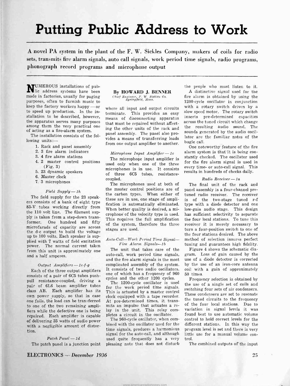
Putting Public Address to Work A novel PA system in the plant of the F. W. Sickles Company, makers of coils for radio sets, transmits fire alarm signals, auto call signals, work period time signals, radio programs, phonograph record programs and microphone output
NUMEROUS installations of pub- lic address systems have been
made in factories, usually for paging purposes, often to furnish music to keep the factory workers happy - or to speed up production. In the in- stallation to be described, however, the apparatus serves many purposes among them the very practical one of acting as a fire -alarm system.
The installation consists of the fol- lowing units :-
1. Rack and panel assembly 2. 3 fire alarm indicators 3. 4 fire alarm stations 4. 2 master control positions
(Fig. 3) 5. 23 dynamic speakers 6. Master clock 7. 3 microphones
Field Supply -1h The field supply for the 23 speak-
ers consists of a bank of eight type 83-V tubes working directly from the 110 volt line. The filament sup- ply is taken from a step-down trans- former. One hundred and fifty microfarads of capacity are across the d -c output to build the voltage up to 100 volts. Each speaker is sup- plied with 7 watts of field excitation power. The normal current taken from this unit is approximately one and a half amperes.
Output Amplifiers -1e-f-g Each of the three output amplifiers
consists of a pair of 6C5 tubes push- pull resistance -coupled, driving a pair of 6L6 beam amplifier tubes class AB. Each amplifier has its own power supply, so that in case one fails, thé load can be transferred to one of the two remaining ampli- fiers while the defective one is being repaired. Each amplifier is capable of delivering 35 watts of audio power with a negligible amount of distor- tion.
Patch Panel -1d The patch panel is a junction point
By HOWARD J. BENNER Chief Engineer, F. 1V. Sickles Co.
Springfield, Mass.
where all input and output circuits terminate. This provides an easy means of disconnecting apparatus that must be repaired without affect- ing the other units of the rack and panel assembly. The panel also pro- vides a means of transferring loads from one output amplifier to another.
Microphone Input Amplifier -1c The microphone input amplifier is
used only when one of the three microphones is in use. It consists of three 6C5 tubes, resistance - coupled.
The microphones used at both of the master control positions are of the carbon types. When either of these are in use, one stage of ampli- fication is automatically eliminated. When better quality is desired, a mi- crophone of the velocity type is used. This requires the full amplification of the system, therefore the three stages are used.
Auto-Call-Work Period Time Signal- Fire Alarm Signals -1b
The unit that takes care of the auto -call, work period time signals, and the fire alarm signals is the most complicated assembly of the system. It consists of two audio oscillators, one of which has a frequency of 960 cycles and the other 1200 cycles.
The 1200 -cycle oscillator is used for the work period time signals. This is actuated by a master control clock equipped with a tape recorder. At pre -determined times, it trans- mits an impulse that actuates a re- lay in the unit. This relay com- pletes a circuit in the oscillator.
The 960 -cycle oscillator, when com- bined with the oscillator used for the time signals, produces a harmonious signal for the auto -call, and although used quite frequently has a very pleasing note that does not disturb
ELECTRONICS - December 1936
the people who must listen to it. A distinctive signal used for the
fire alarm is obtained by using the 1200 -cycle oscillator in conjunction with a rotary switch driven by a slow speed motor. The rotary switch inserts pre -determined capacities across the tuned circuit which change the resulting audio sound. The sounds generated by the audio oscil- lator are the familiar notes of the bugle call.
One noteworthy feature of the fire alarm system is that "it is being con- stantly checked. The oscillator used for the fire alarm signal is used in every time- or auto -call signal. This results in hundreds of checks daily.
Radio Receiver -1a The final unit of the rack and
panel assembly is a four -channel pre - tuned radio receiver. The receiver is of the two -stage tuned r -f type with a diode detector and one low -gain audio stage. This design has sufficient selectivity to separate the four local stations. To tune this receiver it is merely necessary to turn a four -position switch to one of the four stations desired. The above method of selection insures perfect tuning and guarantees high fidelity.
Figure 4 shows the schematic dia- gram. Loss of gain caused by the use of a diode detector is corrected by the use of an iron -core antenna coil with a gain of approximately 50 times.
Frequency selection is obtained by the use of a single set of coils and switching four sets of air condensers. These condensers are set to resonate the tuned circuits to the frequency of the four local stations. Due to variation in signal levels it was found best to use automatic volume control to hold correct levels for the different stations. In this way the program level is set and there is very little use for a manual volume con- trol.
The combined outputs of the input
25
www.americanradiohistory.com

Radio Receiver
Audio Oscillators
Microphone Amplifiers
Patch Panel
Output Amplifier
Output Amplifier r
Output Amplifier
Field Supply
Front and rear views of the public address system
amplifier, radio, and auto -call time signal and fire -alarm signal units are parallel and fed directly to the in- put of the output amplifier which are also in parallel. Each of the previ- ously mentioned units is capable of delivering approximately five volts of audio which is sufficient to drive the output amplifiers to maximum output.
Each unit in the rack and panel assembly has its own power supply so that any one can be repaired while the system is in operation without affecting the operation of the others.
Speaker and Transmission System There are 23 speakers placed
throughout the plant. These speak- ers are so placed that even in the noisiest portions of the plant, all sig- nals are intelligible. In the offices where the noise level is much lower than that of the factory, volume con- trols are placed across the voice coils of the speakers to lower the level of the signals.
Each floor of the building has its separate output amplifiers. The out- put transformer of each amplifier matches a 16 -ohm line. All voice coils of the speakers on each floor are in series to properly match the transformer. The reason the voice coil leads were run directly from the
26
output amplifiers was to avoid the losses accumulated in using match- ing transformers.
Fire -Alarm System Each floor of the building and the
storehouse has a fire alarm station. Each floor also has a signal box which indicates the station from which the alarm was rung. The purpose of this indicator is to advise the members of the organized fire department the location of the alarm so they may report for duty.
Microphone and control panel
To ring an alarm it is necessary to break the glass on one of the sta- tion boxes. This automatically closes a switch that illuminates all the sig- nal lights. The current for these lights passes through a current - operated relay which simultaneously starts the motor driving the rotary switch. This in turn transmits the bugle call signal over the entire sys- tem.
Master Control Positions -3 There are two master control posi-
tions, one in the main office, the other in the production office. The four holes with numbers in the cen- ter are signal lights in parallel with the signal lights in the factory. These indicate the station from which the alarm was rung. The switch button on the extreme right is used for the auto -call signals. The switch on the left of the auto -call button has a dual purpose. When turned to the left it automatically starts the radio and when turned to the right it connects the microphone to the system. The microphone is used for announcements, instruc- tions, or locating a person not listed on the auto -call. The switch next to the left is used to turn off the fire signals so that instructions may be given through the microphone. When the switch is opened, the red light on the extreme lower left lights to indicate that the alarm system is inoperative. After the glass is re- placed on the station box this switch is returned to the normal position which again puts the system in nor- mal automatic operation.
Although never used in the case of a fire this system has worked very efficiently for fire drills. During noon hours the radio gives excellent entertainment, and all announce- ments that are made during working hours are heard by every person in the entire plant.
The entire system is wired in con- duit and every possible part is fire- proof. The line feeding the outfit comes directly from the main line. All these precautions were taken so that in case of fire its operation will not be interrupted until every person is out of the building. As a final safety measure powerful flood lights are placed to cover the entire inside of the plant. These are operated by relays that close when the current fails. The power for these lights is furnished by storage batteries.
December 1936 - ELECTRONICS
www.americanradiohistory.com

Pero 6.tAM CLOCK
TIN____II1.
.= :,
111111 .._....
(Pn-Dv° 2? O ó 9 .
°°E e °°b.
i á
elF1CLEI
1 IM813
COMPLETE CIRCUIT OF
PUBLIC ADDRESS SYSTEM
at F. W. Sickles plant
II ----
_ -
4F -C3- C» Q [-i
QV7P(/7 Afre? 6-" FOqT
OV7A'/7 4"" FL e0e
Qf/7/ez7 .4.r 34" .ti00e
Aad. Hw aa
/414 /*Anl.t/
www.americanradiohistory.com

Fig. 1
Fundamental circuit
Fig. 2 Uses of second full -wave circuit
+ 100 per cent
50 per cent
Fig.3 Provision of half -voltage tap
A B C A ... . x Secondary voltages
Average voltage '"" Instan/aneous vo//age
o i 277' Output voltage at no load
Fig. 4 Wye connection characteristics
o
JSecondary voltages _``: `Average
vo//age
A
` ` ̀ 111.
"-Instantaneous vo/tage
Output voltage A B C
A B C A
© Secondary currents
QOutput current
Fig. 5 Load characteristics
Three Phase Rectifier Circuits For rectifiers having a separate cathode for each anode, such as the Ignitron, a new circuit has been developed which enables stock transformers to be used
THE number and variety of circuits, or transformer connec-
tions, which have been devised for use with various rectifiers, are very large indeed. These circuits range from the simple single phase half wave connection, as employed in small battery charging equipments, to complex multiple zig -zag and forked circuits, frequently used to supply d -c power in traction and electrolytic applications. Each cir- cuit has been evolved to give promi- nence to some characteristic feature, or to suit the individual require- ments of a certain type of rectifier. Thus, certain connections are char- acterized by high apparatus utiliza- tion, some by a flat regulation characteristic, or by a minimum al- ternating component in the output current; while others may be par- ticularly adapted to multiple anode - single cathode arc rectifiers, to high vacuum diode tubes, or to hot cathode gas -filled devices.
The circuit to be discussed herein is restricted to rectifiers having a separate cathode for each anode, as for example the Ignitron, to which it is especially well adapted. It pos- sesses, in fair measure, all of the
By A. J. MASLIN Transformer Engineer
TVeetinghouse Elec. 4 Mfg. Company
desirable characteristics previously mentioned. In addition, it is fre- quently possible to set up the circuit without obtaining special trans- formers. If the desired output volt- age happens to correspond with one of the standard transmission or distribution voltages, stock trans- formers may be utilized.
This circuit is frequently employed to supply d -c power at moderate or high voltages to radio transmitters. It is an especially convenient connec- tion for testing d -c devices, such as tubes, circuit breakers, and the like. When employed to test transmitting tubes, for example, it is necessary to be able to predict and control the output at short circuit, to avoid com- pletely demolishing the apparatus under test when a failure occurs. As an aid to obtaining the maximum utility from this circuit, the follow- ing discussion will describe in detail the various modes of operation, from no load to short circuit, and present equations, and curves, of the current
and voltage relationships, for each of the several modes.
The Circuit
A delta-wye transformer (or transformers) and six single anode - single cathode rectifiers, connected as in Fig. 1, comprise the circuit. The output voltage contains an alternat- ing component having for its funda- mental, the sixth harmonic of the supply frequency. The circuit thus has the same ripple characteristic as a conventional six anode rectifier, when fed from a star, forked, or double wye connected transformer. By suitably connecting a second three phase full wave circuit, having wye-wye connected transformers, in series (as shown in Fig. 2-A), or in parallel through a balance coil (Fig. 2-B), the fundamental of the alter- nating component of the output volt- age is changed to the twelfth har- monic of the supply frequency. This combination, then, displays the same ripple characteristic as a twelve anode rectifier, fed from a quadruple zig -zag or similarly complicated twelve phase transformer. Another modification of the circuit often has great practical value. If the trans -
28 December 1936 - ELECTRONICS
www.americanradiohistory.com

former bank is wound with an inter- connected, rather than a wye, sec- ondary, a half voltage tap is avail- able as part of the output circuit, as indicated in Fig. 3. When the half voltage tap is desired, the sec- ondary must be interconnected, to prevent saturation of the trans- former core by the residual magneto - motive force, resulting from d -c in neutral voltages of the wye.
. First Mode of Operation
The instantaneous terminal to neutral voltages of the wye connected secondary are indicated in Fig. 4-A. The maximum voltage difference be- tween terminals A and B occurs at the instant X, between B and C at Y, and between C and A at Z. By vir- tue of the valve -like characteristic of the rectifiers, it is the maximum voltage difference between any two of the terminals which appears at the output terminals. The instanta- neous value of this maximum voltage difference (or output voltage) for all the terminals, is represented by the ordinate subtended between the up- per and lower envelopes (the heavy wavy lines) of the terminal to neutral voltages. When redrawn (as
in Fig. 4-B), the output voltage is seen as a direct voltage with an alternating voltage or ripple super- posed. The fundamental component of this ripple voltage, as was pre- viously noted, is a sixth harmonic of the supply circuit frequency. Figure 4-B, then, is the no-load out- put voltage of the circuit.
When a load is connected to the output terminals of the circuit, the current which flows must transfer from one secondary winding to the next, as each in turn achieves the highest potential. This transfer in- volves the decay of current in one winding and the simultaneous growth of current in another; it is frequent- ly called overlap. Since the trans- former and the supply system con- tain reactance, this transfer or over- lap requires time. It begins at the instant of voltage equality of two terminals (at P in Fig. 4-A), and continues until the decaying current is zero. The larger the current to be transferred, the greater the in- terval, or angle, of overlap. During this interval the two phases involved are shorted, or connected together through two of the rectifiers. The potential of the relinquishing phase
is increased by the amount of its reactive voltage, while that of the acquiring phase is similarly reduced. When the current in the retiring phase reaches zero, it is prevented from reversing by the valve action of the rectifiers; thus, the upcoming phase assumes he total current, and carries it until it, in turn, transfers to the next succeeding phase. If the load circuit contains sufficient in- ductance, the output current will be substantially free from ripple. Then, as soon as the upcoming phase has assumed the total current, that cur- rent is constant and unvarying, and can produce no reactive voltage. The potential of that phase then jumps to its open circuit value, immediately the transfer is complete. The volt- ages in the circuit, under a load of the type described, are thus no longer as shown in Fig. 4, but are as illustrated in Figs. 5-A and 5-B, while the currents involved are as indicated in Figs. 5-C and 5-D.
For loads resulting in overlap angles (µ) of less than 60 degrees, there is an interval between current pulses of opposite polarity, during which the windings of a given phase are idle and carry no current. This
aSecondary voltages
E,
QOutput voltage A B C j >9'4
e C A Secondary currents
n
I, V
IDOutput current
Fig.6 Maxi mum load characteristics
Secondary vo Itages
A E2
';a1
CDOutput voltage
A B
atel OP4 B C A
® Secondary currents
Ä
I2;
CID Output current
Fig. 7 Delay angles of 0-30°
A 30
ciDSecondary voltages
Output voltage
B C A Secondary currents
A
12 r
°
, , I\ ,,I\
4) Secondary voltages
Output voltage
B G A
CDSecondary currents
A
I2,
a) Output current Output current
Fig.B Fig. 9 Delay angle of 30° Delay angle of 60°
ELECTRONICS - December 1936 29
www.americanradiohistory.com

is clearly shown in Fig. 5-C. As the load increases, the period of idleness decreases until, for the maximum load under. the first mode of opera- tion (µ = 60°), it is zero. The volt- ages and currents for this critical load are indicated in Figs. 6-A to 6-D.
Formulae have been derived, which are applicable when the load, in nature and magnitude, conforms with the foregoing description. It should be noted particularly that the derivation of these equations in- volves the following assumptions :
1-Zero resistance throughout the circuit. The effect of resistance is to reduce the output voltage. The amount of this reduction is approxi- mately the wattmeter copper loss of the circuit divided by the output cur- rent (Watts/I) .
2-Reactance lumped in the trans- former secondary. Reactance in the primary or supply lines, may be re- placed by an equivalent secondary re- actance.
3-Zero reactance in the lead to any individual rectifier.
4-A large inductance in the load circuit.
5-Zero rectifier drop. Tube or arc drop reduces the output voltage and, like resistance drop, should be deducted from the calculated value to obtain the true output voltage.
Using the symbols : E8-Transformer secondary volt-
age to neutral, r.m.s. Is-Transformer secondary cur-
rent, r.m.s. E -Output (d -c) voltage, aver-
age value. I -Output current.
X -Reactance per phase, lumped in secondary, ohms.
µ -Duration of transfer (angle of overlap), electrical de- grees.
1, 2, 3-Subscripts denoting 1st, 2nd and 3rd mode of operation.
The equations are: El= 1.17 E8 (1 +cosµ) (1)
.816 I, X cos = 1 (2)
E8
Isi = .816 I,
[1 3 (2+cosµ) (sing-(1+2cosM)µlr/180)11/2
2r(1-cosµ)= J
= .816 I [1-3¢(µ)1l/' (3)
The expression f1 -31,b (µ) ]i is plot -
30
ted as a function of cos AL in text books dealing with rectifiers, or the curve, Fig. 10, may be used.
The Kv -a capacity of the trans- former bank required is :
Kv-a=3E8I8, (4) Neglecting the effects of overlap, an approximate rating for the trans- former is :
Kv -a = 1.05 El I1 (5) which, in comparison with 1.26 EI for the double wye circuit, and 1.33 EI for the quadruple zig -zag circuit, is very satisfactory indeed.
The above equations, (1) to (5) inclusive, are applicable only for those loads which give rise to an overlap angle of 60 degrees or less (µ<60). This range, however, usually includes full load and nomi- nal overloads for a given installa- tion, and is the range included in the first mode of operation of the circuit.
Second Mode of Operation
If p. were to increase beyond 60 degrees, each secondary winding of the transformer would be required to carry currents of opposite polarity simultaneously. Since this is clearly
1.0
0.99
0.98
0.97
0.96
0.95
0.94
0.93 1.0 0.90 0.80 0.70 0.60 0.50
Fig.10 Expression in rectifier calculation
impossible in this circuit, some other means of permitting an increase in load must come into play. Under this new or second mode of operation, the current must increase in magni- tude but not in duration. It is in- teresting to note that this require- ment is not found in circuits having a separate phase for each anode, such as the star, forked, or double wye connections. In them, separate windings carry the currents of op- posite polarity; thus, these circuits can, and do have anode or secondary currents of one polarity having a duration greater than 180 degrees.
When phase A is carrying the total current, and phase B is trans- ferring to phase C, it is evident that phase A cannot begin its trans- fer to phase B until phase B has.
completed its transfer to phase C. When overlap begins at the instant of voltage equality (P in Fig. 4-A), the voltage causing the transfer be- gins at zero value and increases, However, if the overlap of phases B and C is not complete until after the instant of voltage equality of phases A and B, the voltage avail- able to cause transfer from phase A to phase B, when that transfer begins, is greater than zero, and increases as the interchange pro- gresses. The higher the voltage in- itially available to cause transfer, the larger the current that can be transferred in the allotted interval of 60 degrees. Delayed ignition of the upcoming phase is, then, the phenomena which accompanies an increase in load during the second mode of operation of the circuit. In this manner a larger current is transferred without exceeding the available interval, and the duration of a current pulse of one polarity does not exceed 180 degrees. The heavier the load the greater the de- lay, for all loads up to short cir- cuit.
When the load is such that the delay angle 4, is between zero and 30 degrees, the voltages and cur- rents are as indicated in Figs. 7-A to 7-D. The. instantaneous output voltage does not drop to zero at any time. As the load increases, the output voltage decreases until, when 4) equals 30 deg., it is mo- mentarily zero at three points per half cycle. The voltages and cur- rents for this load are illustrated by Figs. 8-A to 8-D. As the load current continues to increase, 4,
likewise increases, and the instan- taneous output voltage reverses un- til, at the load for which 4, is 60 deg., the average value of the output voltage is zero, as shown by Figs. 9-A to 9-D. This may be called short circuit, but only in a restrict- ed sense. It will be noted that the transformer secondary voltages are not zero, due to the large induct- ance which is still a part of the output circuit. This inductance maintains the output current con- stant. Hence, during the interval that one phase alone carries the total current, there are no reactive drops to reduce the voltage of that phase below its no load value. Dur- ing transfer, however, the current in either of the overlapping phases
December 1936 - ELECTRONICS
www.americanradiohistory.com

Secondary voltages
-E3
CD Output voltage
A B
A C B
(1:ID Secondary currents Secondary currents
Secondary voltages
E3 =0
Output voltage
444*
I3. Y
B C A
I3y Output current Output current
Fig.11 Fig.12 Dotfa for third mode of operation Conditions atshort circuit
2.5 0.75 0.74 0.73 I e3
2.0 0.72 I3 cos e Fig.14
first mode' 0.7 0.8 0.9 10 0.6
1.5
Fi 15
1.0 Second mode \
Third 0.16 mode
Fig. 13
0.5 - 0.15 -lez = 1z
0.74 0° 10° 20° 30° 40° 50° 60°
0.2 0.4 IX
ITEs
0.6 0.8
Fig. 13,44 and 15 Calculating and operating data
1.0
is not constant, and their voltages are affected by the resulting reac- tive drop. From inspection of Figs. 9-A and 9-C, it may be said that the transformer output is at zero power factor; or the circuit may be thought of as functioning alternate- ly as a rectifier and as an in- verter.
The voltage and current relation- ship during the second mode of operation have been analyzed, and the following equations obtained:
E2 = 2.025 Es sin (60°-4)) (6)
ß =60° -cos 1 .816 I2X
Es
Is2=816 I,[1-3 1/2
1.117 cost¢ +.314 sink cos(i) + 1.3 sin4-7r/31
27r (cos2 60 -4))
For convenience when making cal- culations, values of L,/I, have been computed, and are plotted as a function of the angle .0 in Fig. 13.
Eq. (6), (7) and (8) apply only during the second mode of operation (¢ from 0 to 60 degrees inclusive), and their derivation involves the same assumptions as equations (1) to (5).
Third Mode of Operation
Starting with the load correspond- ing to = 30 deg.a mode of opera -
tion, which results in zero transform- er voltage at short circuit, has been synthesized. This third mode re- quires the gradual elimination of the load circuit inductance. When the load is such that 4 equals 30 deg., the instantaneous output voltage is momentarily zero, as shown in Fig. 8-B. If a further increase in load current results - not in an increase of 4) as above - but, in an increase in duration of the periods of zero voltage just noted, the transformer secondary voltages will be zero when the output circuit is shorted. To function in this manner, the wave shape of the secondary current must undergo a marked change. As the periods of zero voltage lengthen, the duration of the flat top of the cur- rent wave must decrease until, at short circuit, the current is purely sinusoidal. This is the only wave shape which will, through reactive drop, reduce the transformer volt- ages to zero in this circuit. The out- put current now is not constant, but carries a ripple. Figures 11-A to 11-D show the voltages and currents for a load within the range of this mode of operation, while Figs. 12-A to 12-D apply at short circuit.
Using the symbol I9 to indicate the maximum value of the output cur- rent, and O to represent the angle through which the secondary volt- ages are finite (i.e. above zero) ;
the following equations have been de- rived :- E3 =2.025 Es (1 -cose) (9)
cose =1.4113X 1 (10) Es
[27r cos2e+(60 -47r)cose13 -l-
7(1+cose)2 3 sine cose -6 sine -30+41x11/2 (11)
7x(1+cose)2 J
Here e is in radians. Values of I9,/I, have been determined, and are plotted as a function of cos e in Fig. 14.
It should be noted that for all values of ii., and all values of 0 with- in their respective ranges, and for e = 60 deg., the average value of the output current, and its maximum value, are equal. In other words, due to the large inductance in the load circuit, the output current is a pure direct current. However, when the load is such that e is less than 60 deg., this is no longer true, due to the ripple current present in the out- put. The ratio of average to maxi- mum value gradually decreases until, at short circuit (0 = 0), it has fallen to 0.955.
The complete characteristic of the three phase full wave rectifier circuit, when operating in accordance with the three modes described, has been plotted from the equations given, and is as shown in Fig. 15.
ELECTRONICS - December 1936 31
www.americanradiohistory.com

By H. F. MAYER General Electric Company,
Schenectady, N. Y.
Automatic Selectivity
Control
Radio receiver selectivity should be adjustable, the control taking place in the intermediate frequency amplifier. Methods of automatic control which widen the band on strong signals. narrow it on weak stations are described
RADIO engineers are becoming more and more aware that
means must be provided in modern home receivers for changing the se- lectivity according to the nature of the received signal. Otherwise there can be no truly high-fidelity recep- tion; such is the layout of the broad- cast spectrum and such is the field strength pattern in the region of most listeners. The following notes on methods of automatically chang- ing the selectivity characteristics were presented by Mr. Mayer at the Rochester Fall meeting of the IRE and attracted considerable interest. It is planned that his mathematical analyses of methods of using tubes as variable reactances will be pub- lished soon in Electronics. - The Editors.
THERE are several ways of using a tube as a variable reactance,
particularly where a capacity react- ance is obtained by a phase -shift method. These circuits are shown in Fig. 1 where the tube acts as a re- actance across a tuned circuit. In both A and B, R is small compared to the reactance of C. L is small, correcting the phase to as near 90 deg. as desired. Often L may be omitted. In A the plate resistance does not matter; in B it must be high. Figure 1C draws lagging in- stead of leading current. Here R is small compared to the reactance of L and C is the compensating react- ance. In B increasing the mutual
conductance (Sm) of the tube in- creases the dynamic capacitance, low- ering the resonant frequency of the tuned circuit. In C the frequency is raised. The electronic capacitance obtained by A or B is approximately RCS,,,.
In applying these circuits to a de - tuning system of automatic selec- tivity control, the primaries of all transformers are detuned in one di- rection; the secondaries in the other direction. By using a tube as a ca- pacity on all primaries, and as an in- ductance on all secondaries sym- metrical detuning may be obtained
(A)
1st I. F.
or converter
(B) Detuning
tubes
11MI11.
110,
with only one control voltage. Otherwise two oppositely directed voltages are required. Furthermore it is desirable for the detuning tubes to be biased to cut-off at maximum selectivity rather than for one tube at cut-off and one to be at maximum Sm, since the alignment and Q of the circuits are most important under this condition.
Since detuning lowers the gain, the ASC will aid the automatic voltage control.
ASC by electronic variation of the coupling of the transformers is a more satisfactory system than con-
o+ 7y. Cast LE
.L
(C)
Detector
32 December 1936 - ELECTRONICS
www.americanradiohistory.com

Fig. 4.-(Left) Q control on one stage. Top curve, no feedback. (Center) Coupling control. Top, no feedback. (Right) Coupling and Q control, no
feedback on bottom curve
trol by detuning. It requires, at most, one extra tube per transformer. The coupling control tube can be made to increase or decrease the ef- fective coupling (Fig. 3A) with in- creasing S,n depending upon the po- larity of the transformer. The net- work across the secondary is the same as in Fig. 1B. The coupling is adjusted to the maximum selec- tivity desired with the coupling tube biased to cut-off. Then as Sm is in- creased the selectivity curve broad- ens and becomes double peaked ex- actly as if the coils were pushed closer together physically. Symmetry is retained. The gain, however, de- creases as the band widens. The
Amp.
Coupling tube
Amp.
(A)
(C)
Coupling tube
A
Amp.
ASC aids the AVC in holding down strong signals.
The circuit in Fig. 3C behaves very much like that of Fig. 3A except that the gain increases as the band widens, more rapidly at first and then approaching a limiting value.
If we reverse one winding of the transformer in Fig. 3A or C, we may adjust the coupling to the maximum band width desired with the coupling tube cut off, and use a negative con- trol voltage. Then for strong sig- nals, the Sm of the coupling tube is small and the band width maximum, and for weaker signals Sm increases and narrows the band, at the same time increasing the gain. Unfortu-
Coupling tube
Figs. I and 2 (opposite page)-Electronic reactance control; ASC symmetrical detuning circuit. Fig. 3 (above)-Electronic coupling and Q control circuit
ELECTRONICS - December 1936
nately, if Sm becomes too great, oscillation occurs, which fact limits the usefulness of this circuit a great deal. A way of limiting the gain of the feedback tube to a definite value would make this circuit en- tirely practical, and perhaps prefer- able to the other type, for two rea- sons : It is possible to obtain selec- tivity better than the transformer it- self has, with some extra gain thrown in; and the second, the extra tube can be eliminated by using the circuit of Fig. 3D.
Q Control
Analysis shows that for the case of electronic feedback from sec- ondary to primary the coupling is effectively changed by an amount k\/Sm where k is a constant depend- ing on the circuit parameters.
Beers has described an ASC sys- tem which might be classified as a Q -control system wherein strong signals cause each tuned circuit to be damped by the plate resistance of a tube. For band widening it would seem preferable to increase coup- ling, since the slope of the resonance curve is not decreased and the same useful band width could be obtained under worse conditions of interfer- ence. However, when seeking in- creased selectivity, Q control is in some cases preferable to coupling control. The curves of Fig. 6 illus- trate this point. Both curves are down 37.5 times at 10 kc. from reso- nance, but the curve for a high -Q
transformer is obviously more de- sirable than the curve A where the
33
www.americanradiohistory.com
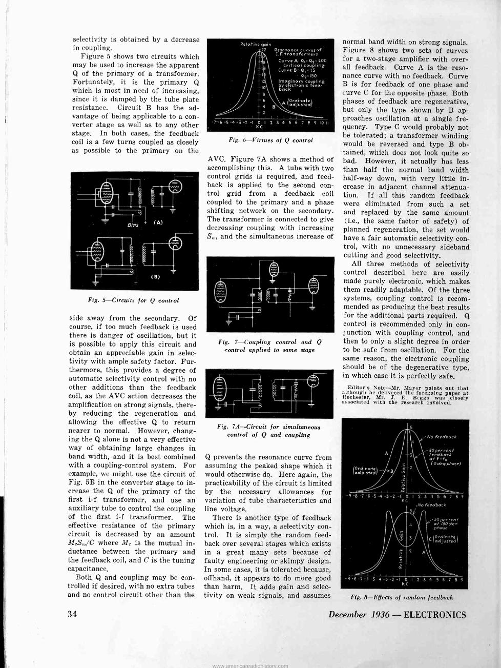
selectivity is obtained by a decrease in coupling.
Figure 5 shows two circuits which may be used to increase the apparent Q of the primary of a transformer. Fortunately, it is the primary Q which is most in need of increasing, since it is damped by the tube plate resistance. Circuit B has the ad- vantage of being applicable to a con- verter stage as well as to any other stage. In both cases, the feedback coil is a few turns coupled as closely as possible to the primary on the
Fig. 5-Circuits for Q control
side away from the secondary. Of course, if too much feedback is used there is danger of oscillation, but it is possible to apply this circuit and obtain an appreciable gain in selec- tivity with ample safety factor. Fur- thermore, this provides a degree of automatic selectivity control with no other additions than the feedback coil, as the AVC action decreases the amplification on strong signals, there- by reducing the regeneration and allowing the effective Q to return nearer to normal. However, chang- ing the Q alone is not a very effective way of obtaining large changes in band width, and it is best combined with a coupling -control system. For example, we might use the circuit of Fig. 5B in the converter stage to in- crease the Q of the primary of the first i -f transformer, and use an auxiliary tube to control the coupling of the first i -f transformer. The effective resistance of the primary circuit is decreased by an amount MtSm/C where /If, is the mutual in- ductance between the primary and the feedback coil, and C is the tuning capacitance.
Both Q and coupling may be con- trolled if desired, with no extra tubes and no control circuit other than the
34
Relative gain -22 Resonance curves of
I.F. transformers Curve A: Qt. Q2=200
Critical coupling Curve B: Q1=75
Q2=150 Imaginary coupling byelectronic feed- back
Ordinate adjusted
-7-6-5-4-3-2 -I 0 I 2 3 4 5 6 7 8 9 10 U KC
Fig. 6-Virtues of Q control
AVC. Figure 7A shows a method of accomplishing this. A tube with two control grids is required, and feed- back is applied to the second con- trol grid from a feedback coil coupled to the primary and a phase shifting network on the secondary. The transformer is connected to give decreasing coupling with increasing Sm, and the simultaneous increase of
Fig. 7-Coupling control and Q control applied to same stage
Fig. 7A-Circuit for simultaneous control of Q and coupling
Q prevents the resonance curve from assuming the peaked shape which it would otherwise do. Here again, the practicability of the circuit is limited by the necessary allowances for variation of tube characteristics and line voltage.
There is another type of feedback which is, in a way, a selectivity con- trol. It is simply the random feed- back over several stages which exists in a great many sets because of faulty engineering or skimpy design. In some cases, it is tolerated because, offhand, it appears to do more good than harm. It adds gain and selec- tivity on weak signals, and assumes
normal band width on strong signals. Figure 8 shows two sets of curves for a two -stage amplifier with over- all feedback. Curve A is the reso- nance curve with no feedback. Curve B is for feedback of one phase and curve C for the opposite phase. Both phases of feedback are regenerative, but only the type shown by B ap- proaches oscillation at a single fre- quency. Type C would probably not be tolerated; a transformer winding would be reversed and type B ob- tained, which does not look quite so bad. However, it actually has less than half the normal band width half -way down, with very little in- crease in adjacent channel attenua- tion. If all this random feedback were eliminated from such a set and replaced by the same amount (i.e., the same factor of safety) of planned regeneration, the set would have a fair automatic selectivity con- trol, with no unnecessary sideband cutting and good selectivity.
All three methods of selectivity control described here are easily made purely electronic, which makes them readily adaptable. Of the three systems, coupling control is recom- mended as producing the best results for the additional parts required. Q control is recommended only in con- junction with coupling control, and then to only a slight degree in order to be safe from oscillation. For the same reason, the electronic coupling should be of the degenerative type, in which case it is perfectly safe.
Editor's Note-Mr. Mayer points out that although he delivered the foregoing paper at Rochester, Mr. J. E. Beggs was closely associated with the research involved.
Ordinate adjusted
-9-8 -7-6-5 -4 -3 -2 Lfeedbuck
percent e
f'dbfoack 0 deq. phase)
-I. 0 1 2 3 4 5 6 KC
,No feedback
SO per cen t at /80 der phase
/Ordinate adjusted
2 A
d I .
7 8 9
-9-8-7 -5-4-3-2-I 0 I 2 3 4 5 5 7 KC
8 9
Fig. 8-Effects of random feedback
December 1936 - ELECTRONICS
www.americanradiohistory.com
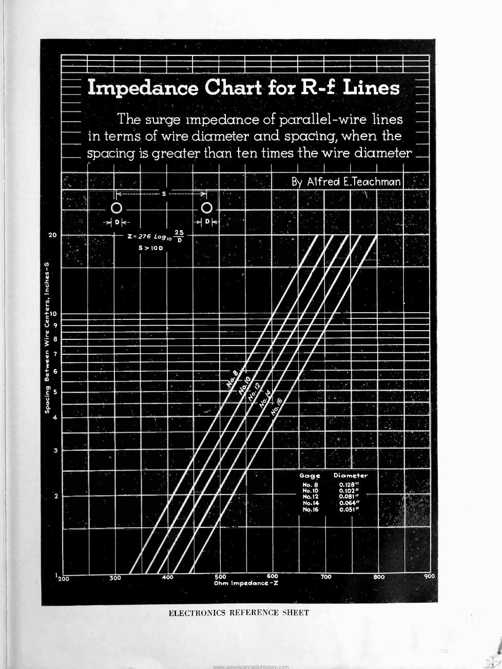
20
tn
N
S u
d =10 01
U 9
8 c 7
3 + 6 e
CD
a
4
Impedance Chart for R -f L The surge impedance of parallel -wire lines
in terms of wire diameter and spacing, when the spacing is greater than ten times the wire diameter
1 1 I
By Alfred E.Teachmc n
Z=276 Lo 2S
9'o p >. 10D
1200 300 400 500 600 Ohm Impedance -Z
Gage Diameter No. 8 0.128" No.10 0.102" No.12 0.081" No.14 0.064" No.16 0.051"
700 800 900
ELECTRONICS REFERENCE SHEET
www.americanradiohistory.com

I.R.E. Fall Meeting [Continued from page 13]
an answer to his question." That there is insufficient talent now avail- able for a wide -spread television service seems certain. Talent must be developed, and it must be given every opportunity to preserve its glamour by the exclusion of audi- ences from television studios. Dr. Goldsmith pointed out that engineers designing television receivers must be "home -minded" and that they must realize that the home is far
H. H. Beverage, New I.R.E. president
less satisfactory for visible enter- tainment purposes than a motion pic- ture theatre. He warned against making wide claims for television and its capabilities.
The final papers of the meeting were on subjects of great interest at the present time. R. B. Dome of General Electric read a paper on feedback amplifiers; J. J. Lamb de- scribed 'his work to improve selec- tivity and freedom from interfer- ence in high frequency receivers. Mr. Dome's paper has been printed in full in the first issue of the RMA Engineer, published by the Engi- neering Division of the RMA.
Mr. Dome developed quantitative relations showing the reduction in harmonic distortion, the improve- ment in regulation of an output tube by the use of negative feedback, and showed the method of developing polar diagrams for a number of rep- resentative feedback circuits. Finally he considered multistate amplifiers employing negative regeneration and gave methods for avoiding oscilla- tion.
Mr. Lamb demonstrated the meth- ods of improving selectivity by the use of crystal filters which narrow the band of frequencies passed by the receiver, and by the use of lim- iter circuits which reduce the am- plitude of transient noises. In dem- onstration, cw signals completely mired up in a locally generated noise (sparks from a vibrator) were made intelligible by a combination of band narrowing and amplitude reduction methods. The efficiency of Mr. Lamb's circuits and apparatus was clearly evident to the listeners.
Antenna Line Terminations [Continued from page 19]
for stray capacity in shielded resist- ance box by resonating circuit (switch in position No. 2) first with box in circuit and then entirely re- moved. Difference in reading if ca- pacitor C. between two conditions equals capacity of box. This value should be added to each reading of C., when circuits are resonated, which is done as above for resistance measurement. The antenna react- ance X. is equal to capacitance rèact-
36
ance value of C. minus capacitance reactance of Co. When reactance of Co is greater than that of C2, then antenna reactance is positive.
When it is found desirable to apply the matching circuits described above and illustrated in Fig. 1 to balanced lines, such as those of the open wire or double concentric types, the value of Xs derived by the partic- ular formula for cases 1 and 2 is halved and placed on each side of the
Ce T X,
= 2 Cs) z+ -3""- Ze=Zo+zo
->zo_ X3 X4 2 2
i
Fig. 8. Balanced circuits
circuit (see Fig. 8), while the value of X. is halved and placed on each side of the circuit for Case 3. Under these conditions the formulas given above apply to the respective cases mentioned. The systems become quite useful in matching a given bal- anced transmission line or r -f cir- cuit into another having entirely dif- ferent input impedance characteris- tics.
In the foregoing analysis of an- tenna matching circuits, they were considered as providing for a given transmission line a termination im- pedance equivalent to an ohmic re- sistance at the fundamental fre- quency. An analysis of the input impedance that such a line "looks into" at various harmonic frequen- cies discloses that it may assume an infinite number of different im- pedances containing resistance and positive or negative reactance com- ponents, the values of which depend upon the termination circuit con- stants as well as those of the an- tenna. The values of antenna resist- ance and reactance may vary widely with frequency. It is apparent, therefore, that for harmonic fre- quencies, stationary . waves of cur- rent and voltage will form on the transmission line as well as in the antenna circuit, unless suitable har- monic filtering is provided either within the vacuum tube transmitter or at the input to the transmission line.
As explained in a previous paper,' the effectiveness of a given filter de- sign for various harmonic frequen- cies depends upon its position in the line with respect to the positions of current and voltage antinodes of the harmonic frequencies along the line.
8 "Suppression of Transmitter Harmon- ics", Carl G. Dietsch, Electronics, June 1933, also "Radio Engineering Handbook", Keith Henney, page Q55, 2nd ed. McGraw Hill Book Co.
December 1936 ,- ELECTRONICS
www.americanradiohistory.com

Views and Reviews
Electric Communication and Electronics By HAROLD PENDER and KNOX
McILWAIN, Editors. Volume 5, Wiley Engineering Handbook Series. (1022 pages, Illustrated; price, $5.00) John Wiley & Sons, publishers, 440 Fourth Avenue, N. Y. City.
A FEW DOZEN PAGES have been the limit of the radio and wire communication material in the usual electrical engi- neering handbook. It has been sand- wiched in between the section on syn- chronous motors and safety first pre- cautions. It should, therefore, be a decided satisfaction to the communica- tions engineer to realize that a refer- ence book has been prepared with his special requirements as the prime edi- torial consideration.
The general style harmonizes with the other volumes of the series and the size is such as to produce a book of convenient proportions. The printing, binding, illustrations, mathematical equations, and tables are handled so as to be of maximum utility. The di- vision into sections rather than into the alphabetical arrangements of for- mer editions of Pender is a vast im- provement, and a comprehensive index at the end of the book helps to make the volume of maximum usefulness.
The sections into which the book is divided are entitled: (1) mathematics, units, and symbols, (2) properties of materials, (3) electric circuits, lines, and fields, (4) resistors, inductors, and capacitors, (5) electron tubes, (6) electromechanical -acoustic devices, (7) circuit elements, (8) high frequency transmission, (9) acoustics, (10) elec- trical measurements, (11) telegraphy, (12) sound -reproducing systems, (13) telephony, (14) facsimile transmission and reception, (15) television, (16) electronic control and navigation equip- ment, and (17) medical applications of electricity. Each section is prepared by specialists, and considering the enor- mous amount of work and the number of persons involved, the text is smooth running and well knit together. This is aided by the fact that the volume tends to be more narrative and less terse and mathematical than some other handbooks which have appeared. While any handbook must lag the field of engineering which it covers, the ma- terial presented is up to date. The Electrical Engineers Handbook, Vol. V, is an excellent job, by and large, and deserves a convenient spot on the desk of any communications engineer.
Notwithstanding its general excel- lence, a few sections appear below par and might be improved. The section
on thermionic vacuum tubes, consisting as it does of extracts from the 1933 I. R. E. standards report, a list of tube characteristics which seems to belong in catalogues rather than in handbooks, and static characteristic curves of a number of unrelated RCA tubes, might easily be improved by presenting more fundamental material. The bib- liographies are not consistent; in some cases they do not appear at all. The sec- tion on electrical measurements could be improved by having a few indepen- dent viewpoints registered instead of taking that of a single organization. Finally, the section on mathematics could be extended and enlarged to ad- vantage.
As far as the entire book is con- cerned, however, these are minor points, and we feel that the authors and edi- tors are to be congratulated on doing a fine job. -B. D.
PRODUCES SLOW SPEED ATOMS
In this vacuum tube chemical elements are heated in the lower portion, thus driv- ing a beam of atoms through a fine hole. In the upper portion of the tube, which contains a liquid air trap, the atoms are slowed down so that they may be "photo- graphed" spectrographically. The tube is
the invention of Drs. Russel Fisher and Benjamin Carpenter of Northwestern Uni-
versity
ELECTRONICS - December 1936
Physik and Technik der Ultrakurzen Wellen, Erster Band (Physics and Engineering of
Ultra -short Waves, Vol. 1)
By H. E. HOLLMANN, Published by Julius Springer, Berlin, Germany, 1936. (326 pages, 381 illustrations, price bound RM86.)
IN THIS VOLUME the author, who is well known for his work on Barkhausen and Kurz oscillators, has made a very comprehensive review of the various methods of generating damped and undamped ultra -short waves. He de- fines such waves as composing the range from 1 millimeter to 10 meters wavelength. The first chapter is de- voted to spark oscillators of various types with open and closed oscillating circuits, the wavelengths and power outputs that have been obtained, and the methods of supplying the input power and modulation. Chapter II deals with regenerative oscillators, cov- ering the single and multiple tube cir- cuits, the loading problem, a few of the tube types particularly suited for short waves, important points in the prac- tical construction of circuits, frequency stabilization, transit -time effects, and modulation methods. Chapter III cov- ers the retarding -field method of gen- erating oscillations including pure elec- tron oscillations of Barkhausen and Kurz, application of resonant circuits, oscillations of higher order, effects of space charge and residual gases, spe- cial tube designs, the theory of elec- tron oscillations with and without res- onant circuits, tube construction and circuits for obtaining the maximum power output, and finally the methods of obtaining modulation. Chapter IV deals with magnetron oscillators both of the split -anode negative -resistance type and the electronic type, the un- derlying theory, construction, the power and efficiency obtainable, and the methods of modulation. The last chapter covers short-wave generation by means of electron and ion streams. The limit of undamped short wave gen- eration is briefly considered.
This book should prove very useful to research workers and engineers in- terested in the problem of ultra -short wave generation. For these it will serve a complete summary of the de- velopment and present state of the art. It is written in fairly simple Ger- man, and the many photographs and curves add very much to an under- standing of the text.
American readers may be somewhat disconcerted by the different designa- tion of some of the commonly named circuits such as the Hartley, Colpitts, and tuned -grid tuned -plate circuits. The treatment of transit -time effects largely from the standpoint of the inversion theory is perhaps somewhat limited.- E. E. S.
37
www.americanradiohistory.com

Radio Service Business Methods BY JOHN F. RIDER and J. V.
NEWENHIZEN. RCA Manufactur- ing Company, 220 pages, price, $6.00.
D -c Voltage Distribution in Radio Receivers BY JOHN F. RIDER, author and pub-
lisher. (92 pages, price 60 cents.)
Resonance and Alignment BY JOHN F. RIDER, author and pub-
lisher. 1440 Broadway, New York City. (92 pages, price 60 cents).
THESE THREE BOOKS for the radio serv- ice man are well described by their titles. They are handy in form, useful in content, practical in subject matter. John F. Rider is so well known to the serviceman fraternity that no long winded description of his latest books needs be given of them or their merits.
The first book handled by RCA has 39 pages by Rider and the remainder by Mr. Newenhizen who is a radio audi- tor and accountant. The second deals with the voltage divider in modern radio equipment, plate circuits, bias arrangements etc. The third book deals with the increasingly important cathode-ray tube as a service tool. It discusses alignment of trimmers, de- tector circuits, superhets, r -f and os- cillator circuits.
Radio Receiving and Television Tubes BY J. A. MOYER and J. F. WOS-
TREL. McGraw Hill Book Company. (635 pages, price $4.00.)
IN THIS THIRD EDITION of their tube book the authors have revamped the old material and added much new data. As in previous editions the emphasis has been on description rather than technical matters. There are chapters on the construction of tubes, how tubes work, testing vacuum tubes, use as de- tector, as rectifiers, amplifiers and as oscillators. There is a chapter on tele- vision tubes, and one of industrial tubes. A final section gives a good table of tubes and their characteristics as the situation stood when the authors were completing their manuscript. In the meantime, however, the tube manu- facturers have brought out quite a few tubes that will not be found in the Moyer and Wostrel table. This is no criticism of the authors-no one could hope to keep up with the steady influx of new tube types.
Einführung in die Angewandte Akustik (Introduction to Applied Acoustics) BY A. HIRZEL, Leipzig, 1935 (216 pp.
with 154 figures. Price 10.70 Ger- man marks minus reductions) .
AFTER PRESENTING the fundamental notions of sound waves and vibrating systems, the book proceeds to discuss the devices for receiving, reproducing, recording and measuring sound waves. The last third of the book is devoted to the properties of Speech, the acou- stics of rooms and the damping of sound in buildings. The authors are members of the German Radio Broad- casting Service so that the radio engi- neer gets his full share of the subject.
In comparison with the well known book bearing the same title by Olson and Massa the German book treats the subject in half the number of pages. The reduced volume is ob- tained mainly by the suppression of mathematical developments and dem- onstrations; on every step the reader is given the proper perspective by the insistence on numerical relations exist- ing between the different factors, in particular in the section devoted to microphones and speech.
Owing to the need for being brief some of the subjects appear easier than they are in reality, for instance, the design of good loudspeakers.
Frequent reference to published ar- ticles-English as well as German- allows the authors to introduce a good number of subjects without filling much space, in particular little known subjects, such as the non-linear re -
DETACHABLE SPEAKER
German radio receiver with speaker which may be separated from chassis
sponse of the ears, the limits of sen- sitivity, the Reisz microphone, the non- linear distortion of microphones. These sources also supply a large number of curves and diagrams not found else- where.-RICHARD RUEDY.
Handbook of Chemistry and Physics BY CHARLES D. HODGMAN, Editor.
(Twenty - first edition). Chemical Rubber Publishing Company, Cleve- land, Ohio. (2023 pages, price $6.00).
To READERS having a training in the physical sciences, reviewing the new editions of the Handbook of Chemistry and Physics is merely a matter of "carrying coal to Newcastle," for it would be hard to find among them a group not already acquainted with this single volume storehouse of infor- mation.
The new edition is divided into sec- tions on mathematical tables, proper- ties and physical constants, general chemical tables, specific gravity and properties of matter, hygrometric and barometric tables, sound, electricity and magnetism, light, quantities and units, and miscellaneous. Considerable material has been revised, 65 pages added. The principal changes made in the 21st edition are the expansion of mathematical tables, the addition of a table of haversines (half versed sines) and material on statistics, a re- vision and enlargement of laboratory arts and recipes, enlargement of the section on photographic formulas, the addition of a new table on commercial plastics, a revised table of isotopes, and the revision of tables on gas volume reduced to standard conditions.
The pages on vacuum tubes and socket connections appear to be some- what out of place in this book. It does not represent fundamental in- formation comparable with the ma- jority of the other data given. Space might better have been devoted to fun- damental tube equations such as Child's and Langmuir's voltage laws, Richard - son's temperature law of emission, tem- perature -emission characteristics of tungsten, molybdenum, tantalum, and other emitters, the elements of tube design, and definitions of the more im- portant tube factors.
To the engineer the tables of LC con- stants, ratios of voltage, power, and transmission units, wire tables, physical constants and abbreviations, definitions, and units and conversion factors will be of frequent use. To the research worker and college student, the Hand- book is the best single -volume, con- venient, and inexpensive substitute for the International Critical Tables with which the reviewer is familiar.-B. D.
38 December 1936 - ELECTRONICS
www.americanradiohistory.com

TUBES AT WORK
IN the June issue of ELECTRONICS, information on tube
life was requested in Crosstalk. Of the several responses
that given by Mr. Briggs, below, is of outstanding interest
Factors Influencing the Useful Life of Vacuum Tubes By THOMAS H. BRIGGS Raytheon Production Corp.
THE USE OF THERMIONIC TUBES in other than radio receiver applications is fre- quently predicated on the fact that ser- vicing must occur at infrequent inter- vals, and that the chances of failure of the equipment employing these tubes must be remote. Unless this be the case it too often happens that some time - tried mechanically -acting substitute will be employed. The broadcast listener rarely has occasion to complain of poor tube life in his receiver. Many sets five or more years old still have the original tubes giving satisfactory daily recep- tion. For industrial use, however, con- tinuous tube operation is usually neces- sary. Thus a year of steady burning in a commercial circuit would be equiva- lent to three to ten years of home radio service.
The best known examples of long service vacuum tubes are those used in telephone repeater stations. Such tubes are said to be. guaranteed for 20,000 hours of life and frequently exceed twice that period. These tubes are man- ufactured under far different conditions than the usual radio receiving tubes. The exhaust is done on slow speed "trolley" type pumping systems. The
c 100 Ú > '
ad 80
5100 V i á 80'
90
50
TYPE 27 I
I I
Mutuo/ conductance
P/ate current
Emission
o 4 6 8 10 Kilo -Hours of Life
12
Life characteristics, triode
ELECTRONICS - December
"formed" type of cathode coating is
used which requires hours to apply. The seasoning processes are long drawn out. All of these things are not now feasible for large scale manufacture of the large variety of broadcast receiving tubes.
Inasmuch as these repeater type tubes are not generally available, com- mercial equipment usually employs the more popular broadcast receiving tubes. These tubes of necessity must have great care exercised during their manu-
-12100
ú 90 80
a 70 .,_IoO
90 c_)
80 á 70
i 00
80 +
v 60
á 40
20
TYPE 24-A Mutual conductance
r
P/ate current
Emission
o o 5 10 15 20 25
Kilo -Hours of Life
Life characteristics, tetrode
facture in controlling all processes from the beginning of the fabrication of raw materials right through to the final testing operation. They must, however, be produced in quantity, be low in price, and be universally available. Because of these three facts these tubes are in de- mand for industrial applications. But these three facts also raise the question of the expected tube life.
There need be but little doubt that re- ceiving tubes will stand up satisfactor- ily for long periods of time if certain simple requirements are met. First, let us see what is possible in the way of life of random samples of popular re- ceiving tubes produced on high speed exhaust machines and burned at rated or over voltage. The three figures show percent variation from published center values of three important tube charac- teristics as plotted against kilohours of life. Two to three tubes each of three types (24A, 27, 58) were burned from
1936
+I Io 3 105
L1ò0 o 95
+I05 ä100 L 95 á 90
c100 d v 75
50
TYPE -58
Mutualconductance
P/ate current
Emission
0 2 4 6 8 IO 12 14
Kilo- Hours of Life
Life characteristics, pentode
10 to 25 thousand hours at normal heater voltages and normal or slightly over plate voltages (250-275 v.). The life testing was not terminated through failure of the tubes to perform. At the end of 25,000 hours the three type 24A tubes were placed in a receiver and performed as well as new tubes for local reception, and were only slightly inferior for . weaker signals.
It will be noticed that although the emission may vary over wide ranges or decrease to a tenth of the original value, that the plate current and mutual conductance curves remained relatively steady. This emphasizes one important point, namely, that proper choice of the type of tube is necessary for commer- cial equipment. Thus, a tube with low plate current (5-10 ma.) will be able to maintain these values even though the emission is greatly reduced. Whereas, an audio output tube of 30-40 ma. plate current would have this value seriously reduced with a 50% reduction in emis- sion.
An additional fact brought out during this life testing was that certain char- acteristics varied up and down over wide ranges. This apparently is indica- tive of changes in the condition of the cathode or grid surfaces due to burning. They are also fluctuations which would probably be encountered during actual service.
One point which is true of broadcast receivers as well as industrial vacuum tube equipment is that the life expec- tancy of the tubes used is dependent upon the permissible latitude of tube characteristics consistent with satisfac- tory circuit performance. Thus, a relay circuit demanding tube plate current to be within 10% of the published nominal would have caused rejection of the 24A's shown in the figure after 6,000 hours and of the 27's after 2,000 hours. Whereas, a circuit permitting a 20%
39
www.americanradiohistory.com
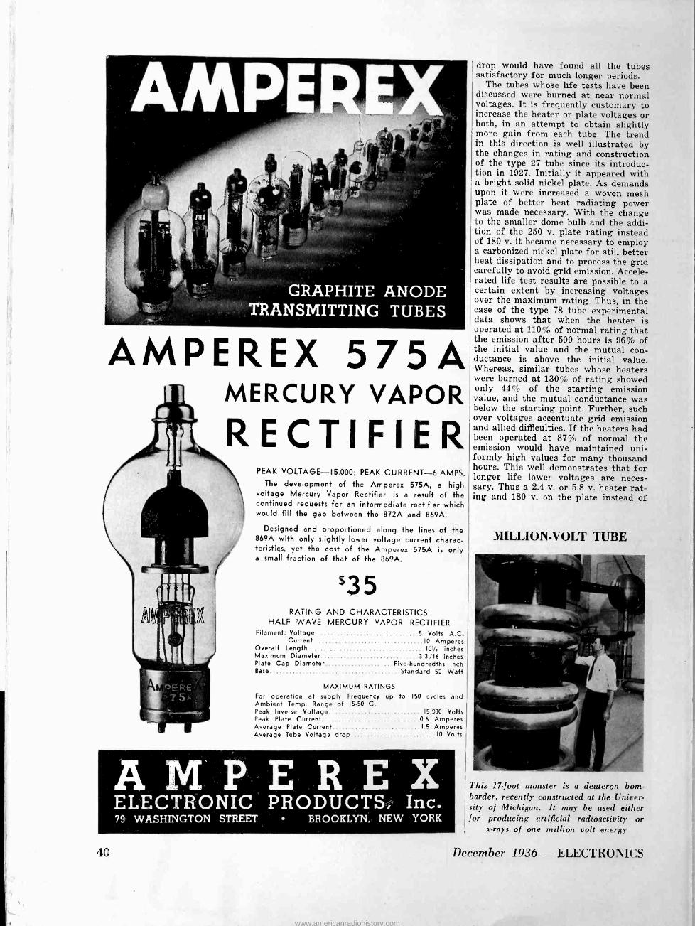
GRAPHITE ANODE TRANSMITTING TUBES
AMPEREX 575A MERCURY VAPOR
RECTIFIER PEAK VOLTAGE -15,000; PEAK CURRENT -6 AMPS.
The development of the Amperex 575A, a high voltage Mercury Vapor Rectifier, is a result of the continued requests for an intermediate rectifier which would fill the gap between the 872A and 869A.
Designed and proportioned along the lines of the 869A with only slightly lower voltage current charac- teristics, yet the cost of the Amperex 575A is only a small fraction of that of the 869A.
'35 RATING AND CHARACTERISTICS
HALF WAVE MERCURY VAPOR RECTIFIER Filament: Voltage 5 Volts A.C.
Current 10 Amperes Overall Length 10/2 inches Maximum Diameter 3-3/16 inches Plate Cap Diameter Five -hundredths inch Base Standard 53 Watt
MAXIMUM RATINGS For operation at supply Frequency up to 150 cycles and Ambient Temp. Range of 15-50 C. Peak Inverse Voltage Peak Plate Current Average Plate Current Average Tube Voltage drop
15,000 Volts 0 6 Amperes 15 Amperes
10 Volts
AMPERE X ELECTRONIC PRODUCTS, Inc. 79 WASHINGTON STREET BROOKLYN, NEW YORK
40
drop would have found all the tubes satisfactory for much longer periods.
The tubes whose life tests have been discussed were burned at near normal voltages. It is frequently customary to increase the heater or plate voltages or both, in an attempt to obtain slightly more gain from each tube. The trend in this direction is well illustrated by the changes in rating and construction of the type 27 tube since its introduc- tion in 1927. Initially it appeared with a bright solid nickel plate. As demands upon it were increased a woven mesh plate of better heat radiating power was made necessary. With the change to the smaller dome bulb and the addi- tion of the 250 v. plate rating instead of 180 v. it became necessary to employ a carbonized nickel plate for still better heat dissipation and to process the grid carefully to avoid grid emission. Accele- rated life test results are possible to a certain extent by increasing voltages over the maximum rating. Thus, in the case of the type 78 tube experimental data shows that when the heater is operated at 110% of normal rating that the emission after 500 hours is 96% of the initial value and the mutual con- ductance is above the initial value. Whereas, similar tubes whose heaters were burned at 130% of rating showed only 44% of the starting emission value, and the mutual conductance was below the starting point. Further, such over voltages accentuate grid emission and allied difficulties. If the heaters had been operated at 87% of normal the emission would have maintained uni- formly high values for many thousand hours. This well demonstrates that for longer life lower voltages . are neces- sary. Thus a 2.4 v. or 5.8 v. heater rat- ing and 180 v. on the plate instead of
MILLION -VOLT TUBE
This 17 -foot monster is a deuteron born - border, recently constructed at the Univer- sity of Michigan. It may be used either for producing artificial radioactivity or
x-rays of one million volt energy
December 1936 - ELECTRONICS
www.americanradiohistory.com

600 FEET FROM SUNLIGHT
To insure uninterrupted production as
well as maximum safety, mine operators depend on SYNTHANE laminated Bake-
lite for insulating mining machinery.
SYNTHANE-the dependable insula- tion that protects equipment in the air,
on the ground, under the ground, on and under water-adds to your products the same degree of reliability.
SYNTHANE LAMINATED BAKELITE SHEETS RODS TUBES
FABRICATED PARTS
Send for Sample Book
SYNThANE CORPORATION ,, OAKS PENNA
www.americanradiohistory.com
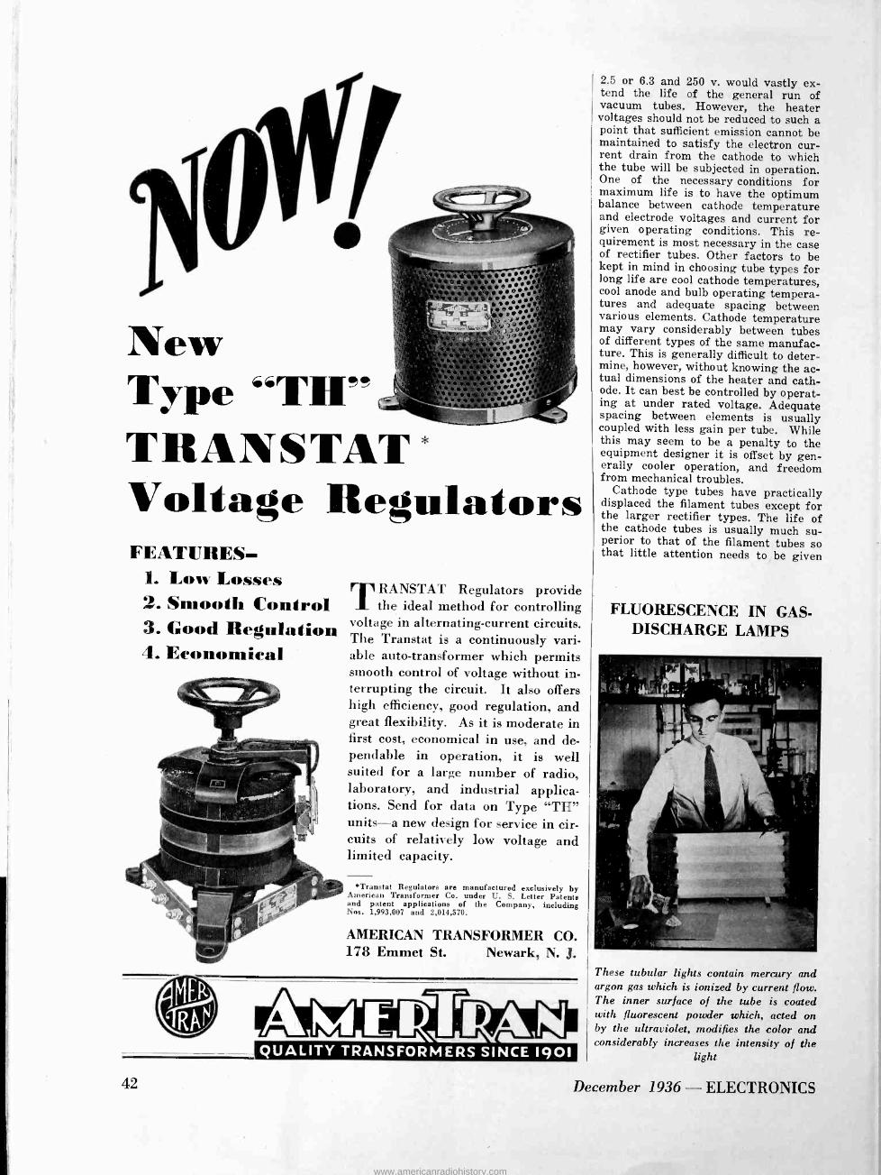
`10 New Type "TlI" TRANSTAT Voltage Regulators FEATURES.
1. Low Losses 2. Smooth Control 3. Good Regulation 4. Economical
42
TRANSTAT Regulators provide the ideal method for controlling
voltage in alternating -current circuits. The Transtat is a continuously vari- able auto -transformer which permits smooth control of voltage without in- terrupting the circuit. It also offers high efficiency, good regulation, and great flexibility. As it is moderate in first cost, economical in use, and de- pendable in operation, it is well suited for a large number of radio, laboratory, and industrial applica- tions. Send for data on Type "TH" units-a new design for service in cir- cuits of relatively low voltage and limited capacity.
*Transtat Regulators are manufactured exclusively by American Transformer Co. under U. S. Letter Patents and patent applications of the Company, including Nos. 1,993,007 and 2,014,570.
AMERICAN TRANSFORMER CO. 178 Emmet St. Newark, N. J.
QUALITY TRANSFORMERS SINCE 1901
2.5 or 6.3 and 250 v. would vastly ex- tend the life of the general run of vacuum tubes. However, the heater voltages should not be reduced to such a point that sufficient emission cannot be maintained to satisfy the electron cur- rent drain from the cathode to which the tube will be subjected in operation. One of the necessary conditions for maximum life is to have the optimum balance between cathode temperature and electrode voltages and current for given operating conditions. This re- quirement is most necessary in the case of rectifier tubes. Other factors to be kept in mind in choosing tube types for long life are cool cathode temperatures, cool anode and bulb operating tempera- tures and adequate spacing between various elements. Cathode temperature may vary considerably between tubes of different types of the same manufac- ture. This is generally difficult to deter- mine, however, without knowing the ac- tual dimensions of the heater and cath- ode. It can best be controlled by operat- ing at under rated voltage. Adequate spacing between elements is usually coupled with less gain per tube. While this may seem to be a penalty to the equipment designer it is offset by gen- erally cooler operation, and freedom from mechanical troubles.
Cathode type tubes have practically displaced the filament tubes except for the larger rectifier types. The life of the cathode tubes is usually much su- perior to that of the filament tubes so that little attention needs to . be given
FLUORESCENCE IN GAS - DISCHARGE LAMPS
These tubular lights contain mercury and argon gas which is ionized by current flow. The inner surface of the tube is coated with fluorescent powder which, acted on by the ultraviolet, modifies the color and considerably increases the intensity of the
light
December 1936 - ELECTRONICS
www.americanradiohistory.com

Centralab Controls, Centralab Resistors and the new Selector
Switches have enjoyed an increased
acceptance in 1936.
That acceptance can only be inter- preted as a recognition of QUALITY.
We pledge for 1937 a continuance of that same high standard of excellence.
Centralab Division of Globe Union, Inc., Milwaukee
Canterbury Rd. Kilburn N.W. England
118 Ave. Ledru-Rollin, Paris
ELECTRONICS - December 1936 43
www.americanradiohistory.com

a
C
dog/
UNITED TUBE S drue
TYPE 304-A
The UNITED 304-A has m'e c h a n i c al refinements that are clearly evident when compared with any other make tube.
The accompanying illus- tration shows our im- proved UNIT ELEMENT ASSEMBLY supported by two c h a n n e l members running from stem to stem. This assures posi- tive and accurate relation- s h i p between filament, giid and plate.
All elements are made into a complete fixed unit in our mount department, so that it only remains for the glass department to seal this unit into a bulb, eliminating the alignment by eye method.
UNITED type 304-A is approved by the FCC for Broadcast use under rule 127.
Write for data sheet, applying to type 304-A.
PRICE $97.50
UNITED ELECTRONICS COMPANY 42 SPRING ST., NEWARK, N. J.
44
those types, other than the 2 -volt bat- tery line. In such cases frequent atten- tion to batteries would mean attention also to tubes, and cost of tube replace- ment if more frequent would be insig- nificant compared to power supply.
Where almost instant response of a circuit is required without having the tube heaters constantly burning it is necessary to use filament type tubes. However, the life of cathode type tubes with only heater voltage applied for most of the time is very long.
So far only electrical failures of tubes have been discussed. The mechan- ical failures may be classed as open heater circuits, short circuits, improp- erly assembled tubes, and glass leaks. Only in exceptional cases will such troubles be encountered. Where a high degree of insurance against mechanical failure is imperative it is usually feas- ible to operate the tubes in their circuit for 10 to 100 hours under a closer than normal supervision. In this manner ex- pectancy of long mechanical life can be made much more certain.
Tubes Measure Protecting Finishes in Automobile Manufacture FOR THE FOLLOWING information on electron tube applications the Editors are indebted to Mr. L. A. Danse, metal- lurgist of the Cadillac Motor Car Co., Detroit, Mich.: An interesting applica- tion of electronic tubes has been made in the Cadillac Laboratory. It is a control device for indicating the end point on the abrasion testing apparatus for checking anodized coatings on pis- tons and for checking paint and var- nish coatings on car parts. In the old method of reading, the end point was indicated by means of a flashlight cell and bulb with a wire cat -whisker (feeler) which rested against the coat- ing. Inasmuch as the flashlight com- bination used considerable voltage and current, c o a tin g s were sometimes burned through before actual failure had occurred, and premature end points thus indicated. By substituting an electron tube amplifier, the current through the cat -whisker is reduced to a negligibly small amount and the po- tential involved is low. By utilizing the amplification characteristics of the tube, an indication is given on a good sized lamp even though the potential and current through the cat -whisker which is not sufficient to burn through any part of the coating before the end point is reached.
Electronic devices are also used in this laboratory for measuring the thickness of painted coats on automo- bile bodies, etc. With such instru- ments it is possible to plug into any convenient electric light socket and to measure the thickness of the paint on any part of an automobile body, sheet metal or other metal parts.
December 1936 - ELECTRONICS
www.americanradiohistory.com

2IOMANTENNA1è MICROPHONE
1
TRANSMITTER
(6Th
N
E
AMPLIFIER
AMPLIFIER
HIGH QUALITY stations demand high quality equipment. That's why General Radio measuring equipment, monitors
and control apparatus are so widely used in the leading broad- cast stations.
MIKE
ITH the Type 730-A Transmission Monitoring Assembly the station op-
erating staff is assured of peak transmitter performance at all times. Measurements of percentage modulation, carrier shift, carrier noise and hum level, program monitoring, a -f harmonic distortion and over -modulation are made rapidly and accurately. The Assembly is composed of three independent and self -operated units: Type 731-A Modulation Monitor (FCC Approval No. 1521), $195.00; Type 732-A Distortion & Noise Meter, $205.00; Type 733-A Oscillator, $62.00. The complete Type 730-A Assembly with all tubes, cords and accessories is priced at $642.00.
HUNDREDS of stations are using the G -R Visual -Type Frequency Monitor
(FCC Approval No. 1452) . This instru- ment is composed of a frequency monitor and a frequency deviation indicator. The latter is equipped with a large-scale indi- cating meter with a range of -100 to +100 cycles. The Visual -Type Frequency Meter is priced at $560.00.
THE new G -R Type 586 Power Level Indicators are very compact and are
equipped with copper -oxide rectifier -type indicating meters. Two models are sup- plied, one with a normal- and the other with a high-speed meter. Prices are $55.00 and $60.00.
THE G -R line of high-grade audio -frequency trans- formers includes a transformer for every broadcast
station use; single or double button microphone to grid, mixer or line to p -p grid, plate to grid, plate to line or mixer, etc. Prices range between $6.00 and $10.00.
TYPE 653 Volume Controls are small, compact and have exceptionally long life.
Extremely low noise level is secured by using only one sliding contact with both switch blade and contacts of the same material. These controls are stocked in four imped- ances and are priced at $12.50.
For Complete Information Write for Catalog 85-E
Address: General Radio Company, Cambridge, Massachusetts
GENERAL RADIO ELECTRONICS - December 1936
(11
ere4
bpi
w+1
grm
groi
COMPANY 45
www.americanradiohistory.com
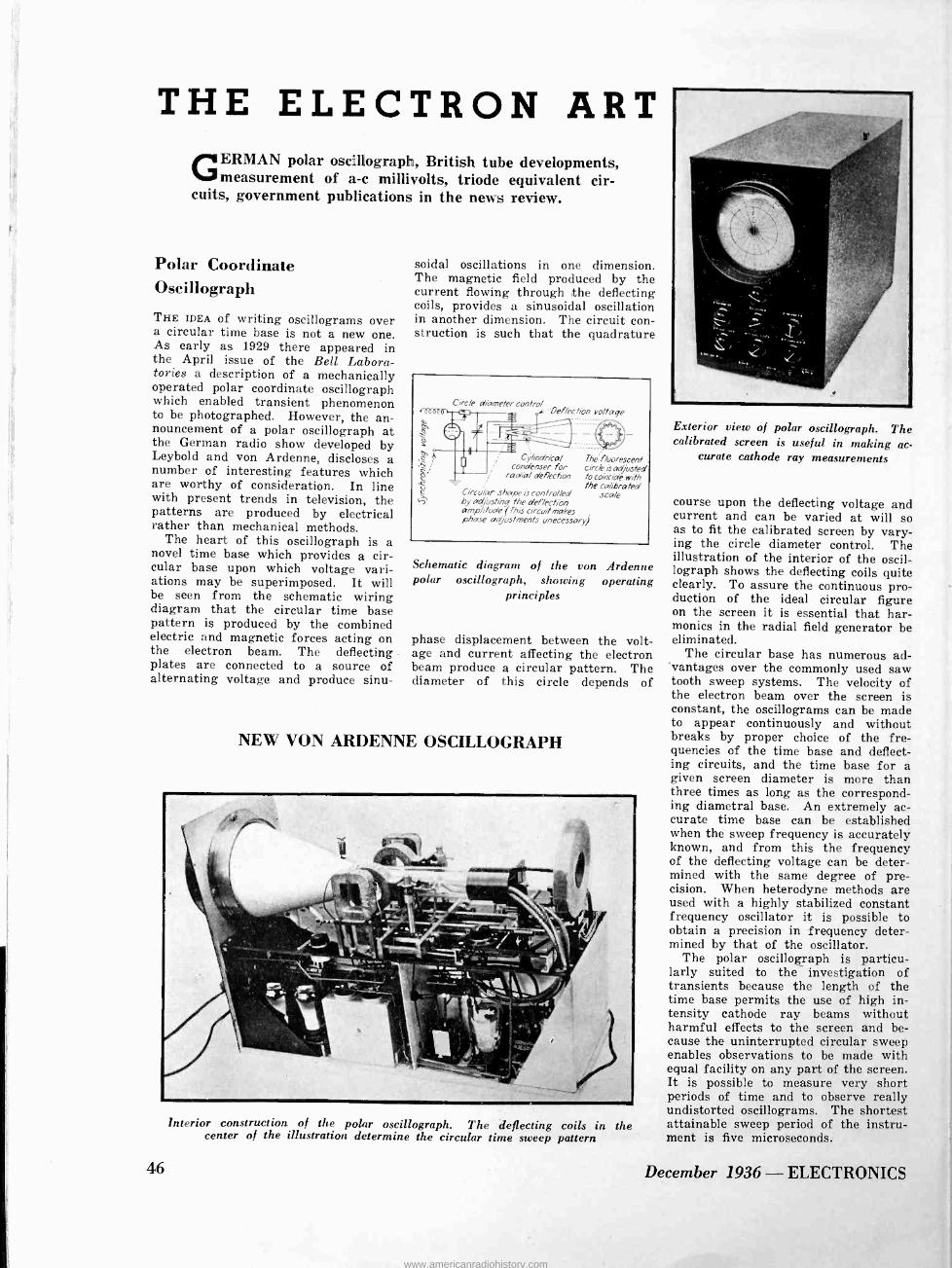
THE ELECTRON ART GERMAN polar oscillograph, British tube developments,
measurement of a -c millivolts, triode equivalent cir- cuits, government publications in the news review.
Polar Coordinate Oscillograph
THE IDEA of writing oscillograms over a circular time base is not a new one. As early as 1929 there appeared in the April issue of the Bell Labora- tories a description of a mechanically operated polar coordinate oscillograph which enabled transient phenomenon to be photographed. However, the an- nouncement of a polar oscillograph at the German radio show developed by Leybold and von Ardenne, discloses a number of interesting features which are worthy of consideration. In line with present trends in television, the patterns are produced by electrical rather than mechanical methods.
The heart of this oscillograph is a novel time base which provides a cir- cular base upon which voltage vari- ations may be superimposed. It will be seen from the schematic wiring diagram that the circular time base pattern is produced by the combined electric and magnetic forces acting on the electron beam. The deflecting -
plates are connected to a source of alternating voltage and produce sinu-
46
soidal oscillations in one dimension. The magnetic field produced by the current flowing through the deflecting coils, provides a sinusoidal oscillation in another dimension. The circuit con- struction is such that the quadrature
Circle diameter control 4, -Deflection voltage
Circo/ar shape is controlled by adjusting the deflection ampli/We (This circuit makes phase adjustments unecessary)
Cylindrical Thé fluorescent condenser for cirdk is adjusted
radia/ deflection to coincide with the calibrated
scale
Schematic diagram of the von Ardenne polar oscillograph, showing operating
principles
phase displacement between the volt- age and current affecting the electron beam produce a circular pattern. The diameter of this circle depends of
NEW VON ARDENNE OSCILLOGRAPH
Interior construction of the polar oscillograph. The deflecting coils in the center of the illustration determine the circular time sweep pattern
Exterior view of polar oscillograph. The calibrated screen is useful in making ac-
curate cathode ray measurements
course upon the deflecting voltage and current and can be varied at will so as to fit the calibrated screen by vary- ing the circle diameter control. The illustration of the interior of the oscil- lograph shows the deflecting coils quite clearly. To assure the continuous pro- duction of the ideal circular figure on the screen it is essential that har- monics in the radial field generator be eliminated.
The circular base has numerous ad- vantages over the commonly used saw tooth sweep systems. The velocity of the electron beam over the screen is constant, the oscillograms can be made to appear continuously and without breaks by proper choice of the fre- quencies of the time base and deflect- ing circuits, and the time base for a given screen diameter is more than three times as long as the correspond- ing diametral base. An extremely ac- curate time base can be established when the sweep frequency is accurately known, and from this the frequency of the deflecting voltage can be deter- mined with the same degree of pre- cision. When heterodyne methods are used with a highly stabilized constant frequency oscillator it is possible to obtain a precision in frequency deter- mined by that of the oscillator.
The polar oscillograph is particu- larly suited to the investigation of transients because the length of the time base permits the use of high in- tensity cathode ray beams without harmful effects to the screen and be- cause the uninterrupted circular sweep enables observations to be made with equal facility on any part of the screen. It is possible to measure very short periods of time and to observe really undistorted oscillograms. The shortest attainable sweep period of the instru- ment is five microseconds.
December 1936 - ELECTRONICS
www.americanradiohistory.com

ARMORED CABLE W CG
O
° Q. et W _ H Q W
W
H W z c Q
W J Q V W V z Q
z W W
> ac W
W J Q
C W 2
RECEIVER CORDS
J Q
ó
BARE WIRE
Here's a Real Saving for
RADIO MANUFACTURERS
A 11 d `VIÌAT L Si rincJ!
CRESCENT CORD SETS WITH PARTS - READY TO INSTALL KEEP COSTS DOWN by buying your cord sets from us, com-
pletely assembled with switches, sockets, fittings, etc. No matter how complicated or intricate the set may be, we guarantee 100%
perfect cords ready for installation.
We specialize in this work. Our testing and inspection is most
complete. You get the advantage of the savings, not only in money,
but in time and convenience that buying cord sets from us will give
you, PLUS the elimination of wiring failures when the set is in use.
Send us your blue prints for prices on quantity production.
ASSEMBLY CORDS
SHIELDED CORDS
ANTENNA CORDS
WRITE US-We will be glad to show you samples of work we are doing.
Address Department E.
CRESCENT MANUFACTURES BUILDING WIRE
u-
v O
rn 411
o m z Ñ v n cc
Vf
70
ao
rn
7v
N rn
00 70
gESÇEN co
rn
& CABLE CO. INC.
TRENTON, NEW JERSEY.
CRESCENT ENDURITE SUPER -AGEING INSULATION RUBBER POWER CABLES
ELECTRONICS - December 1936 47
www.americanradiohistory.com

Assure better performance
S.S.WHITE MOLDED
RESISTORS 1,000 OHMS
TO 1,000,000 MEGOHMS
/He /7[C"lVeCIliTP/Z ZiGJtie NOISE TESTED At slight additional cost, re- sistors will be supplied indi- vidually "noise -tested" to this specification: "For the com- plete audio frequency range, resistors shall have less noise than corresponds to 1 part in 1,000,000." (For values up to 10 megohnrs)
Featured by noiseless operation, de- pendable resistance value, non -hygro- scopic material and rugged mechanical strength, the ability of these resistors to perform satisfactorily, regardless of climatic conditions, has been amply demonstrated. TRY THEM on your radio and electronic equipment - WRITE for descriptive circular.
The S. S. WHITE Dental Mfg. Co. INDUSTRIAL DIVISION IO East 40th Street, Room 2310E, New York, N. Y.
BRUSH Sphetiea MICROPHONE.
A specially designed, general purpose microphone for remote pickup, "P. A." and commercial interstation transmission work. Low in price . . . but built to Brush's traditionally high mechani- cal and electrical standards. Wide frequency response. Non - directional. No diaphragms. No distortion from close speaking. Trouble -free operation. No button current and no input trans- former to cause hum. Beautifully finished in dull chromium. Size only 21/8 inches in diameter. Weight 5 oz. Output level minus 66 D. B. Locking type plug and socket connector for either suspension or stand mounting furnished at no extra cost. Full details, Date Sheet No. 13. Free. Send for one.
BRUSH Are/
1884 E. 40th St.
MICROPHONE
4!.
For after dinner and convention speakers, lecturers, etc. Gives great mobility - the smallest, lightest microphone on the market. Size 11/2 x 11/4 x 3/g. Weight with coat attach ment less than I oz. Special internal construction and rubber jacketed outer case insures quiet operation. No interference from breathing noises, etc. Typical Brush sound cell response and trouble -free operation. Details on request.
DEVELOPMENT COMPANY
CLEVELAND, O.
MICROPHONES MIKE STANDS TWEETERS HEAD PHONES LOUD SPEAKERS
48
Recent British Tube Developments As USUAL, the news of the Olympia Radio Show, as reported in Wireless Engineer is interesting and instructive of what is taking place in radio devel- opments across the Atlantic. The cur- rent report in the October issue, from which this abstract has been compiled, devotes most of the space to test and measuring equipment, although a fair portion is given over to recent develop- ment of British electron tubes.
The outstanding novelty in the report is the Harries "all stage" multi -element tube, manufactured by Harries Ther- mionics, Ltd. This tube is an elabora- tion of the "critical distance tetrode" of Harries, or the "beam power tube" which has been developed independently by Schade of the RCA Mfg. Co. in this country. The all stage "valve" contains an indirectly heated cathode, five grids, and a plate, so that a seven element tube results. The grids are brought out to separate base pins, and by making suitable grid connections on the socket, the tube can be given characteristics suitable for any stage in the receiver.
Control
Grid
Screen
700V
Control
Grid
Anode Screen
*60K
Control Grid
A Anode *250
Contro Grid
C A.VC.
B
Anode *2501?
A.V.C.
[11
*70V
In all applications the grid nearest to the cathode is used as the control grid, since it is fully screened from the plate by the other grids, and its leads is brought out to a terminal at the top of the tube. When the tube is used as a triode, all other grids are con- nected to the plate, as shown at A. Four different connections are possible when it is desired to use the tube as a tetrode, and each connection imparts somewhat different characteristics to the "custom built tube". Two possible tetrode connections as a voltage ampli- fier are shown in B and C. The con- nection at B gives higher plate resist- ance and higher transconductance than the connection at C. When automatic volume control is used, the control voltage is not applied to the control grid but to one of the other grids. It is claimed that this results in the advantage of operating the grid on the straight line portion of the Ec - Ir char- acteristic. The connection at D may
December 1936 - ELECTRONICS
www.americanradiohistory.com

be used to provide a "critical distance" output tube.
The idea of changing the character- istics of a tube by changing the grid connections is not new, and has been used in this country for some years with multi -element tubes such as the 59, 46, and 89. However, the idea of building a tube which, with proper connections, can be used with satisfac- tory (even if not optimum) charac- teristics in all stages of a receiver is attractive because of the possibility of reducing the total number of variations of tubes in commercial use. Failing this, the idea is still attractive as it may tend to reduce the rate of increase at which new tubes are being made commercially available, many of them without filling any real need.
In addition to this universal tube, two types of tubes of physically small dimensions are also reported. One of these, a Mullard acorn tube appears to be very similar to the 954 tube devel- oped by Thompson and Rose. They are intentionally designed to have short electron paths and transit time, and are provided with lead-in connections sim- ilar to the acorn tubes used in the United States.
The other type of "midget" tube is made by Hivac, and appears to be sim- ilar in appearance to the Northern Electric peanut or N tubes, although of smaller dimensions. These tubes can be obtained with ceramic bases of low dielectric loss, but do not appear to be as well suited to use in the extremely high frequency range as the acorn tubes.
. e .
CALTECH'S COSMIC VAN
In this shielded trailer is the cosmic ray apparatus with which Dr. Carl D. Ander- son (extreme right) discovered the posi- tron, ready for transportation to Pike's Peak. Dr. Anderson's winning of the
Nobel Prize was recently announced
OSCILLOGRAPHS TDIMeoDE BY DU MONT Demanded by universities, research laboratories and industrial for their unfailing scientific accuracy, advanced design and performance.
Du Mont Oscillographs are available in
three models to meet a variety of needs. All models feature the basically new pat- ented Du Mont sweep circuit, which is the most linear yet devised. All models feature the improved Du Mont Cathode Ray tubes which provide a hair line trace absolutely uniform over the entire screen, extreme bril- liancy, long life and high sensitivity. Sim- plicity of control, calibrated scale, improved synchronizing circuit and quality in every part are yours when you buy Du Mont.
THE THREE MODELS ARE:
No. 154-A lightweight portable Oscillograph with a 3" Du Mont Cathode Ray tube for the man who wants to take the instrument to the job.
No. 148-A larger unit with provision for either 3" or 5" Du Mont Cathode Ray tube. For aver- age laboratory or industrial uses.
No. 158-An instrument of unlimited application for jobs which demand the most complete and finest oscillograph made. Supplied complete with 9" Du Mont Cathode Ray tube.
concerns superior
It will pay you to get complete data on these great Du Mont instruments. They are the greatest quality value available. Years of usage have proven Du Mont's leadership. Write for complete details and prices.
ALLEN B. DU MONT Laboratories, Inc. Upper Montclair, New Jersey Cable Address: New York, WESPEXLIN
Frequency Measuring Service wQiO rr Many stations find this exact measuring serv- ice of great value for routine observation of transmitter performance and for accurately calibrating their own monitors.
MEASUREMENTS WHEN YOU NEED THEM MOST
R.C.A. COMMUNICATIONS, Inc. Commercial Dept.
A RADIO CORPORATION OF AMERICA SERVICE
66 BROAD STREET NEW YORK, N. Y.
THIS NEW RESISTOR is available Rough Wound or completed to 1'o accuracy Two purposes are served by the Model M Resistor: that of a unit ready to be calibrated by purchaser to meter requirements or as a complete unit of standard accuracy with soldering lug terminals.
Where manufacturers wish to Wind lower resistance values, we can supply Type M Winding Forms.
Write for details and prices.
Type M: 1 Watt; Accuracy 1%. Resistance Range .05 to 500,000 ohms. Size: 1" dia., x '/z" high.
WIRE WOUND RESISTORS PRECISION RESISTOR CO. - 332 BADGER AVE. - NEWARK, N. J.
ELECTRONICS - December 1936 49
www.americanradiohistory.com

KI E W AP3-18 EMLE
PORTABLE SPEECH INPUT EQUIPMENT
Endorsed by leading Broadcast Stations Compact, high fidelity audio system in- corporating refinements ordinarily associ- ated with studio equipment. High gain remote amplifier and power supply, de- signed for use with either dynamic, veloc- ity or inductor microphone. Three channel input, each controlled by individual lad- der attenuators and wire wound tapped master gain potentiometer. Output feed
one or two broadcast loops simultaneously. 50, 200 or 250 ohm input as ordered. For operation with A.C. power supply shown or with battery box. Units connected by 6 ft. cable with lock type plugs. Overall gain 93 db. Tubes: 2-77, 2-6A6 and I-80. The amplifier and power supply units mounted in sturdy reinforced fibre carrying cases with cover protecting the attractive, engraved dural front panels. Size of amplifier carrying case 93/4 x II x 20. Power supply case 9 x 20 x 93/4. Amplifier unit may be equipped with any standard type microphone input connector. Write for catalog sheets and prices.
REMLER COMPANY, Ltd., 2101 Bryant Street, San Francisco
REMLER THE RADIO FIRM AS OLD AS RADIO
50
R E LAYS BY GUARDIAN are tailor-made to your specifications at
no greater cost than a standardized type
Illustrated are two variations of a Series 60 Guardian Relay. Long Base -round base-stud mounted-bracket mounted-innumerable contact combi- nation coil resistances-all sizes, types, and shapes of contact points in any metal. And this hut one of many in the Guardian Line of Relays.
Solenoids - Step-up Switches - Locking Relays - Time -Delay - Overload - Counting Units - Mercury Switches - Special Applications to your order.
Write Today for "Relays by Guardian".
C U A R D I A N ELECTRIC MFG. CO. 1625 W. Walnut St., Chicago, Ill.
A -C Millivolt Measurements THE ADVANTAGES of a rectifier type meter with its high sensitivity has re- cently been extended to enable meas- urements to be made of low alternating voltages. As reported by Paul Mac- Gahan in the September 1936 issue of Instruments, this has been accomp- lished by using a bridge type of copper oxide rectifier feeding the D'Arsonval instrument as a load. The limitations of wave form error, temperature coeffi- cient, and non -linearity which charac- terizes copper -oxide rectifiers neces- sitates the use of a high resistance in series with the rectifier to reduce the effect of these variables upon the ac- curacy of the instrument. Because of the introduction of this high series re- sistance it has not been possible, here- tofore, to use this type of measuring device for small a -c voltages.
100/I Step up transformer
Voltage to be measured
e 0 0 O 0 O 0 .
Dsirsonva/ instrument
Compensating 1 resistor .11 \\ANY
Copper oxide disk rectifiers
The difficulty has been overcome by inserting a step-up transformer be- tween the voltage to be measured and the series resistor and rectifier arrange- ment. By means of a transformer having a step-up ratio of 100 to 1, an input voltage of 30 millivolts produces three volts across the rectifier and series resistor, and this can be readily measured. Of course the introduction of the transformer introduces an addi- tional element which can easily restrict the frequency range over which the meter will give satisfactory indications, but the arrangement as shown in the schematic wiring diagram is intended to provide a handy portable unit of fair accuracy rather than a laboratory standard.
Reduction of Machine Noise UNDER THE TITLE of "The Role of Acoustical Measurements in Machinery Quieting" in the October 1936 issue of the Journal of the Acoustical Society of America, E. J. Abbott gives a sum- mary of a number of difficulties which have been encountered in making acous- tical measurements on machines. The advantages and disadvantages of the method of frequency analysis and sound level intensity measurements are set forth.
December 1936 - ELECTRONICS
www.americanradiohistory.com

17,000 Hour Tubes Impossible?
Not With Tantalum ! Heintz and Kaufman, Ltd., makers of
Gammatron transmitting tubes, recog- nized the world over for their supe-
rior performance, were the first of
the pioneers in the use of tantalum. They state:
"Over ten of our production types of
tubes use tantalum elements. It has
been found far superior to any other material. The Dollar Steamship Lines and Globe Wireless, Ltd., have been using our 500 watt Gammatrons for several years and show service records as high as 17,000 hours! We feel this is an enviable record, and un-
doubtedly tantalum has helped in
achieving the same through its prop- erty of absorbing gases present with-
in the tubes."
The facilities of the Fansteel labora- tory are at the disposal of manufac-
turers wishing to investigate the pos-
sibilities of tantalum, tungsten or
molybdenum.
ELECTRICAL CONTACTS of tungsten, molyb- denum, platinum, silver and alloys, designed and made by Fansteel, afford extra depend- ability in relays and other electronic operated devices.
FANSTEEL METALLURGICAL CORPORATION
NORTH CHICAGO, ILLINOIS
TANTALUM . COLUMBIUM
TUNGSTEN . MOLYBDENUM
ELECTRICAL CONTACTS
Equivalent Networks of Triodes F. B. LLEWELLYN, writing in the Oc- tober issue of the Bell System Tech- nical Journal, reviews the status of triode equivalent circuits and brings the subject up to date so as to apply to very high frequencies. in his ar- ticle, "Equivalent Networks of Neg- ative -Grid Vacuum Tubes at Ultra - High Frequencies", the various steps in the development of the equivalent network are outlined, and it is shown that the series circuit consisting of a resistanceless generator and a resist- ance equal to the internal plate resist- ance, while still useful for elementary discussions and applicable at very low frequencies, is subject to serious limi- tations where rigor of analysis is re- quired or where tubes are used at ultra -high frequencies.
As the frequencies at which tubes are operated increases, the effect of interelectrode capacitance becomes im- portant. To take these capacitances into account the simple series equiv- alent circuit may be modified into a delta by placing capacitances between all of the elements. This elaboration is adequate so long as the resistive components of the various arms can be neglected.
The most general delta network for a negative grid triode consists of three series branches, each containing an internal generator in series with an impedance. This type of network has the disadvantage of employing three generators but by a proper defi- nition of the amplification factor can be reduced to a delta with a single generator.
At frequencies where the effects of transit time of the electrons are only moderately important, the dia- gram given here can be used. This equivalent network has advantages over some other types of networks in that the amplification factors come out to be a real rather than a com- plex number, the impedance in series with the generator is the usual inter- nal plate resistance obtainable from measurement or static characteristics, and the interelectrode capacitances are the usual ones which have been used at lower frequencies.
ELECTRONICS - December 1936
112,e1DVDIf
AT LOW COST
IMPEDANCE BRIDGE
Thru its use, 60 cycle and 1200 cycle measurements of resistance, capaci- tance, and inductance may be made in the ranges and with the accuracy indicated below.
C
I ohm to I megohm
Accuracy below 100 ohms -2% or 0.1 ohms 100 to 100,000 ohms 2% above 100,000 ohms -3%
.00001 to 100 mfd.
Accuracy below 100 mmf.-5% 100 mmf. to IO mfd.-2% above 10 mfd.-3%
IO microhenries to 100 henries
Accuracy below I milhenry-2% or 5 micro -
henries milhenry to I henry -2%
above I henry -3% Priced at only $95.00 net, the Model I -B Impedance bridge is the logical choice of engineers who demand qual- ity apparatus at low cost.
For complete information and details of the FREE TRIAL OFFER, write for Bulletin B-116.
TOBE DEUTSCHMANN CORPORATION
Canton, Massachusetts
CLIP AND MAIL Tobe Deutschmann Corporation, Instrument Division, Canton, Massachusets.
Please send me bulletin B-116 describing the Model I -B Impedance Bridge, with complete in- formation about your FREE TRIAL OFFER.
Name
Street
City State
51
www.americanradiohistory.com

IF
MANUFACTURING REVIEW
News
+ Erie Resistor Corporation has re- cently completed a large addition to its main factory at Erie, Pa., contain- ing over 16,000 square feet and three stories in height. This building houses the plastic molding division and gen- eral offices of the company.
+ Rowe Radio Research Laboratory Co. has been recently established to ren- der consulting service on problems of radio receiver design and to give en- gineering advice in regard to other as- sociated radio and electrical problems. This organization is located at Suite 207-8, 1103 Bryn Mawr Avenue, Chi- cago, Ill.
+ The Bruno Laboratories, Inc. an- nounces their removal from 20 West 22nd Street to their new quarters at 30 West 15th Street, New York City, where they have leased considerable additional space. Here all activities of the organization will be combined although they retain their laboratories at Teterboro, N. J., and Washington, D. C., devoted to aviation.
+ Bausch & Lomb Optical Company has begun a program of fundamental in- vestigations on the chemistry and
New Products
physics of glass surfaces to aid in the development of scientific apparatus and ophthalmic instruments. This work is being carried on at Mellon Institute, where this organization has main- tained a fellowship since 1931 for re- search on plant and production prob- lems in optical technology. Dr. Frank L. Jones will be in charge of this work at the Mellon Institute. An enlarged staff will continue the work on plant problems at the new research labora- tory of the company in Rochester, New York.
+ Mirrophonic sound reproduction equipment has been adopted by Univer- sal Pictures Corporation for their studios. This work includes modern- izing the three fixed scoring and dub- bing channels, using three new addi- tional Mirrophonic recording machines, and installing new equipment in the review rooms.
+ National Union Radio Corporation, 570 Lexington Avenue, New York City, announces the appointment of J. H. Robinson as Director of new product research. Among Mr. Robinson's du- ties will be that of seeking out and analyzing the marketability of new products, patents in the field of radio,
electronics, television and electrical industries.
+ Canadian Broadcasting Corporation has as its new officers Maj. W. E. Gladstone Murray, as General Manager and Dr. Augustin Frigon as Assistant General Manager. These men, associ- ated with the British Broadcasting Corp. and the Quebec Electricity Com- mission, respectively, are well versed in the art of broadcasting and in the knowledge of its problems.
The American Rolling Mill Company has begun the construction of a new research laboratory to replace the building destroyed by fire about a year ago. The building will incorporate the use of porcelain enameled sheets, other decorative metal products, and glass blocks. The building will be located adjacent to the company's offices, in Middletown, Ohio.
+ Belden Manufacturing Company has completed its new manufacturing plant in Chicago, and is still at work on the new plant being constructed at Rich- mond, Indiana. The Chicago building adds 20,000 sq.ft. of floor space and will be used to extend the wire mill and tinning plants.
Electron Microscope Tube ALLEN B. Du MONT LABORATORIES, INC., Upper Montclair, New Jersey, have recently developed an electron micro- scope tube referred to as the Type 889. This tube is designed to demonstrate the principles of the electron lens and how they. can be used to function as a microscope.
The specification of this electron mi- croscope tube are as follows: Diameter of screen 2 inches Overall length of bulb 62 inches Base 7 prong Image Green Type of cathode Indirect heater Filament volts (AC or DC) 15 Filament amperes 1.5 Focus electrode volts 0 to -300 Anode voltage 500 to 1000
In the Type 889 the surface of the oxide coated nickel cathode is enlarged approximately twenty-five times and
52
projected on a fluorescent screen at the end of the tube. The necessary voltage to operate the Type 889 may be obtained from a simple power supply.
Instantaneous Recording Equipment THE "MASTERTONE" is one of the sev- eral new instantaneous recording out- fits manufactured by Recording Equip- ment Mfg. Co., 6611 Sunset Boulevard, Hollywood, Calif. This is equipped with a full synchronous motor, 78 r.p. m.; a precision overhead lathe type feed; built-in pre -amplifier for micro- phone; 12 -inch turntable; matched cut- ting head; balanced crystal reproducing arm; high quality two -cell balanced crystal microphone; 7 watt recording amplifier; 8 inch matched loudspeaker. It lists, complete, for $350.
December 1936 - ELECTRONICS
www.americanradiohistory.com

rß sO 01
dl> es'. Standard
0ss tia / stocks maintained
for audio and power transformer laminations
and shells and frames. Motor laminations a specialty. Big battery of presses for all type and weight stampings. Lab- oratory check maintained on all electrical steel used. Large stock raw material kept on hand for rush work.
Try Us CATALOGUE ON REQUEST
WEBSTER CHICAGO SECTION M -D-22
3825 W. LAKE ST., CHICAGO, ILL.
Proved PERFORMANCE!
There must be a reason why leading sound equipment manu- facturers and expert engineers have approved and adopted Shure
"Ultra" Wide -Range crystal microphones. That reason is Proved Performance .
performance proved by repeated laboratory and field tests . . . performance and service consistent in every way with advanced requirements for high quality sound repro- duction.
Shure "Ultra" Wide -Range Crystal Micro- phones are available (as illustrated) in Grille - Type, Swivel, and Spherical models. List Price, complete with cable...
Write for Bulletin 140MB Licensed under patents of the Brush De- velopment Company. Shure patents pending.
sec R\E, MICROPHONES SHURE BROTHERS MICROPHONE HEADQUARTERS 225 WEST HURON STREET CHICAGO, U.S.A.
Acorn Pentode RADIOTRON announces the RCA -956 acorn type super control r -f amplifier
pentode which reduces cross -modula- tion and modulation distortion. Oper- ating at minimum bias 956 will give a voltage gain of 4 or more at a wave -length of 1 meter.
Coil Form HAMMARLUND MANUFACTURING CO., INC. has developed a giant coil form for use in transmitters. It employs the low loss insulating material known as XP -53, such as is used in the SWF coil forms. No artificial coloring to cause losses. Forms are grooved ribbed to permit air spaced windings for maximum efficiency. Flexibility of mounting is a point stressed; the form may be permanently mounted by means of a special pair of brackets, or tem- porarily mounted in the familiar plug- in coil fashion, in the regulation socket. Hammarlund Mfg. Co., Inc., 424 W. 33rd. Str., New York City.
Analyzer AN A -C BRIDGE and condenser analyzer combination for the radio serviceman has been announced by the Tobe Deutschmann Corporation, Canton, Mass. The particular features of the instrument are the points that in addi- tion to the usual dynamic tests for shorts, opens, and intermittent con- denser conditions, power factor can be read directly, and capacities measured with greater precision than on ordinary capacity meters. It also functions as a resistance bridge.
Built-in neon tube for direct con- denser check, with 6E5 electric eye null indicator for bridge balance. Also uses one OlA tube. Resistance range: 1
ohm to 1 megohm. Capacity range: 10 µµf to 100 µf.
ELECTRONICS - December 1936
a 1Er :r »ochet-Volt-Ohm-
1ff1//lamm
P. e. and-Ae Size: 3 1/16" X 5'/a" x 2%"
DEALER $01 5.00 PRICE
Uses Large 3" Sq. Triplett Instrument A. C. -D. C. Voltage Scales Read: IO -
50 -250-500-1000 at 1000 ohms per volt. D. C. Milliampere Scale Reads: 1-10- 50-2 50. Ohms Scale Reads: Low 1/2-300; High
250,000. Black Molded Case and Panel.
Low Loss Selector Switch. Complete with Alligator Clips, Battery
and Test Leads.
DEALER PRICE $15.00 A Complete Instrument for all servicing
needs. Can be used for all A. C. -D. C. voltage, current and resistance analyses.
LEATHER CARRYING CASE for Model 669, supplied extra.
Very attractive. Of black, heavy leather with finished edges and strap.
WRITE FOR CATALOG
The Triplett Electrical Instrument Co. 2312 Harmon Dr., Bluffton, Ohio Without obligation please send me - More information on Model 666. - I am also interested in
Name
Address
('ity State
53
www.americanradiohistory.com

A1KOIDRE(..US.. GAT.OGG.
LAMINATED BAKELITE
A complete line for radio and related uses
Lamicoid is available in sheets, tubes, rods and fabricated form for a wide variety of uses.
FABRICATED PARTS Made in all shapes and thicknesses, punched and machined to microm- eter accuracy.
RADIO STOCK No. 6028 XXXD Low Power Factor Stock, especially suitable for high frequency radio parts.
TRANSLUCENT LAMICOID Flexible translucent dial stock. White, Amber and Colors. Glossy
or satin finish.
ENGRAVING LAMICOID Lustrous black surface with perma- nent white core, translucent or opaque, eliminating filled letters.
GRAPHIC LAMICOID Lettering and designs made an integral part of the sheet. Opaque or translucent. Glossy Satin or Graphic finish.
COMPLETE DATA Tell us your problem. We'll send data, samples, and the new price Bulletin No. 105.
MICA INSULATOR COMPANY 200 Varick Street, New York; 542 So. Dearborn Street, Chicago; 1276 West Third St., Cleveland. Branches at: Birmingham, Boston, Cincinnati, Los Angeles, San Francisco, Seattle,
Montreal, Toronto.
ulalnllWlnlaauuuallllnNWaI111111u11a1111n1111111alUWanuallolallWuuluIII11WIIu11WIWulnnlnulalanWluulllW WlllauunullnllnWllulu1111n1uIPA
The NEW Magnetic Core Material YEItMANITE
For those who mold cores or shield's. Used by several of the largest manufacturers in cores for
IF and RF transformers Its low cost, stability and uniformity suggest many
uses in other high frequency parts Write
FOOTE MINERAL CO. 1600 Summer St., Philadelphia
F.
g.
n l l l l l l l l 111 I I 1111 I I I I I I I I I I I I I I I I I I I I I I I I I I I I I I I I I 111 I I I I I I I I I I I I I I I I I I I I I I I I I I I I I I I I I I I I I I I I I I I I I I I I I I I I I 1111111 I I I I I I I I I I 111 I I 111 I I I I I I I I I I I I I I I I I I I I I I I 111 I I I I I I I I I I I I I I I I I I I I I I 111111 I I I I I 111 I I I I I I I I I I I I I I I I I I I I I I I1 -C
DYNAMIC MICROPHONES ARE INCREASING IN POPULARITY
because they -have greater sensitivity -are free from inductive pickup -have no background noise -can work with long lines -are sturdiest ever produced -are weatherproof -are small in size -are reasonable in price Write for Latest Bulletin No. 3013
RADIO RECEPTOR COMPANY, INC. 108 SEVENTH AVE. NEW YORK, N. Y.
54
Measuring Instruments GENERA?, RADIO COMPANY, in its Sep- tember -October issue of "The Experi- menter" announces the release of three new products. Type 620-A, a terro- dyne frequency meter and calibrator is designed for frequency measurements above 10 megacycles by using harmonic methods, however, the entire range of frequencies between 300 kc. and 300 mc. can be covered. The accuracy of meas-
urement is 0.1%, or better. Price, rack mounted model $490.00; cabinet model $555.00.
Type 759-A sound level meter per- mits measurements to be made in the range from 24 to 130 decibels above the standard reference level of 10-16 per sq. cm. at 1000 cycles. Price, in- cluding tubes and batteries $195.00.
Type 487-A megohmmeter applies the principle of the ohmmeter to resistance measurements in the megohm range. A vacuum tube voltmeter is the indicator. Between 200,000 ohms and 5,000 meg- ohms, the accuracy is 5%. The top range is 50,000 megohms. Price, in- cluding tubes $95.00.
Carrier Shift Indicator THE SUPREME MODEL 565 carrier shift indicator is now available to amateurs and experimenters. It is reasonable in price but sufficiently versatile in func- tion and accurate in results to serve as the principle means of indicating carrier shift, over -modulation, and serve as a monitor. It covers five amateur bands, 1715 to 200 kc., 3500 to 4000 kc., 7000 to 7300 kc., 14,000 to 14,400 kc. and 28,000 to 30,000 kc. It can be operated as an over -modulation indicator, a carrier shift indicator, to ascertain improper bias, excitation, impedance, etc., an absorption type wave meter, a listening monitor, an in- dicator of proper neutralization, a resonance indicator during tuning pro- cess, an indicator when adjusting the transmitting antenna and as a field strength indicator. A -c and d -c volt and d -c milliampere ranges of 0/7/35/- 140/350/700/1400. Power supplied from batteries which are self-contained. Portable, flexible and accurate. A -c volts circuit calibrated at 60 cycle frequency unless otherwise ordered, at slight additional cost. List price $26.95. Supreme Instruments Corp., Green- wood, Mississippi,
December 1936 - ELECTRONICS
www.americanradiohistory.com

NEOBEAM
OSCILLOSCOPE "lakes S'of!uid Visible"
VIBRATION STUDY Locates vibration instantly. New model
150 Neobeam Oscilloscope permits quick de- termination of efficiency when used with the model 153 vibration pick-up. Range 8000 C.P.S. Detects movements as low as .000003". Portrays vibration on 3" calibrated screen. Supplied also with speaker to permit hearing as well as seeing.
THE NEOBEAM Completely self contained and easy to
operate. Uses latest 6L6 Beam Power ampli- fiers, calibrated sweep. Takes any input from 1 micro -volt to 200 volts. Complete with tubes and ready to operate, $40.00 net. Vibration pick-up $17.50 net. These are quality instruments-fully guaranteed.
SUNDT ENGINEERING CO. (Affiliate of Littelfuse Laboratories)
4248 Lincoln Avenue CHICAGO. ILL.
AUDIO OSCILLATOR TYPE CR -4 BEAT FREQUENCY
Price
$77
Portable, A.C. Operated.
10 cps to 20,000 cps.
Reed for Calibration Check.
High and Low Impedance Outputs.
Direct Reading Dial. Accuracy 2%.
Low Hum and Distortion.
High Output; 30 volts Max.
Drift after warmup Negligible.
Write for Catalog
UNITED SOUND ENGINEERING CO. Manufacturers of Electronic Equipment
2235 University Ave., St. Paul, Minn.
Self-contained Phototube Relay THE TELETOUCH CORPORATION, 37 West 54th St., New York City, announces a self-contained phototube relay, in which both the light source and the phototube are mounted. No separately -mounted
light source is required, the light being reflected by a passing object into the phototube, a feature which greatly adds to the convenience of the device. An earlier model, which made use of a separate amplifier, and required the services of an electrician for installa- tion, was used principally for window - lighting purposes. The latest model contains amplifier and sensitive unit in the same casing, and can be installed simply by plugging into the light -socket. The device is called the "Teletouch Ray".
Mirrophonic AT A RECENT sales convention of Elec- trical Research Products, Inc., at the Hotel Pierre, New York City, a new system for sound reproduction in the theatre was displayed. It has a film pulling mechanism known as the "Ki- netic Scanner" in which a damped me- chanical impedance provides uniform film velocity. It also has an improved optical system in which a physical slit is replaced by a cylindrical lens com- bination. A harmonic suppressor in the amplifier increases the dynamic range appreciably. The speaker system re- sembles that used in the Western Elec- tric Stereophonic three-dimensional sound demonstration in which Leopold Stokowski took part.
ELECTRONICS - December 1936
/ Sp.aca. LL Valuable !
CDintaa.e,ed q,aó.- ,cDnrt',neßhe - Daiiia.(i,le_ and gixed -121tDu,ida..
tha lDrcaL ,dD,lu.tiDn,.
among. D.UlL LCÓRhá.
K M O X --St. Louis
W B B M --Chicago
K Y W --Philadelphia
K W K H --Shreveport
r0a
,7h.eheá. Azzeon, . . .
c( -et. l(6., Jul:2iau1,
SOUTH .AN FRANCISCO
CALIFORNIA
0
POSITIVE PROTECTION
For Your Power Tubes. These light duty overload trip relays have a wide field of use as safety devices on elec- tronic apparatus. Operation is un- usually dependable. Scores of nation- ally known concerns rely on Leach Relays for protection.
Leach Relay Company 5915 Avalon Boulevard,
£'1'111.Los
Angeles, Calif. .."ppge*e" dos
SEND .. gas COUPON woe. g1í . aY Go., opt
cataoB
\.sash 8seod
/11'} VW'
s
-
Navae . Compao9
le.aatess
55
www.americanradiohistory.com
THE"BULLET" DYNAMIC
MICROPHONE
AT LAST an ALL-PURPOSE
Microphone With a sensitivity that provides sufficient power to permit almost unlimited lines ... Different im- pedances to match any amplifier having from five to five hundred thousand ohms input impedance ... A perfect microphone for in- doors yet rugged enough to meet every outdoor purpose ... Tone quality equal to much higher priced instruments of similar type.
Consider these SEVEN out-
standing "BULLET" features
ombined in one microphone Maximum sensitivity
Effective at long dis- tance from amplifier
Wide choice of im- pedances
Attractive, modern appearance Unequaled for severe outdoor work Remarkable tone quality
Moderately priced
A few territories are still open for exclusive distribution
TRANSDUCER CORPORATION
30 Rockefeller Plaza
New York, New York
56
Outdoor Public Address System THE TECHNA CORPORATION, 926 How- ard Street, San Francisco, California, is now ready to market a complete out- door public address system including
microphone, amplifier, and two expo- nential horn type dynamic speakers. The amplifier is mounted in a metal cabinet identical to Techna 21J. The 15 -Watt beam power amplifier provided for use with the 21J series incorporates all the features of advance public ad- dress design and includes the use of the new 6L6 beam power tube. Type 21J4, price $230.00.
Thermocouples RAWSON ELECTRICAL INSTRUMENT COM- PANY of Cambridge, Massachusetts, ap- proached several years ago by MIT professors developed thermocouples for
radio frequency measurements. These converters of heat into electricity have no frequency error up to 60-70 Mc. They measure currents from 5 ma. to 1 ampere. The couple is iron-con- stantan. They are now offered for general sale at $15 each.
Rectifilter FOR SUPPLYING d -c power for speech amplifier filaments in broadcast sta- tions, motion picture theaters, motion picture studios, public address and cen- tralized radio systems, Raytheon has developed a line of battery eliminators known as Rectifilters. They produce d.c. from 110 volts a.c. Experience in two hundred installations indicates that these units not only take the place of batteries but are sometimes superior in results obtained. Their cost is less because of their long life; the service is less than on batteries.
An essential design feature is the stabilized d -c output. A special circuit is used which holds the d -c output sub- stantially constant regardless of the load. Another feature is the high de- gree of smoothing employed. The ripple (a -c) component) remaining in the d -c output is only -80 db and this may be reduced to -120 db through the use of an auxiliary filter.
The most popular Rectifilter is the 12 volt model which has been made in sizes from 1 to 18 amperes with prices varying from $90 to $216.66 to the user.
Further details and prices may be obtained by requesting Bulletin DL48- 118 from the manufacturer, Raytheon Manufacturing Company, Electrical Equipment Division, 100 Willow Street, Waltham, Massachusetts.
THE SIGMA
SENSITIVE RELAY
List Price, $10.00
Jewelled movement. Balanced to operate in any position. Positive operation on 4 milliwatts, D. C.
Single pole, double throw. Mounts in standard 5 -prong tube socket. A useful adjunct to
V. T. controls Supervisory and alarm circuits Signalling.
SIGMA INSTRUMENTS, INC.
388 Trapelo Road, BELMONT, MASS.
December 1936 - ELECTRONICS
www.americanradiohistory.com

PROFESSIONAL
SERVICES
BLILEY ELECTRIC CO. Uratgncra---Slanufacturnrs
Quartz Crystals for standard or special radio frequency applications.
Inquiries Invited. 240 Union station Bldg.
Eric, Poona.
EISLER ENGINEERING CO. Committee, Deafening if Mfg. Eng(neere
Electric Welding Problems, High Vacuum Compound Pumps, Soft and Hard Ulaes Working Equipment, Radio and Electronic Tube Machinery
Special Machinery built to your specifications 7t11 So. Iath Mt. Newark, N. J.
ELECTRICAL TESTING LABORATORIES
Characteristice and Life Tests of Vacuum Tubes
Testa of photo cella, slow lamps, crater lamps. Teste of electronic and optical devices.
80th Street and East End Avenue New York, N. Y.
Phone: Butterfield 8-2600
THAD R. GOLDSBOROUGH REGISTERED PATENT ATTORNEY
Westinghouse Electric, 1916-1930 Patent Attorney, RCA Victor, 1930-1936
fifteen years familiarity with patent matters rrlstlfg to Talking Movies. Television. Radio and I.:leetronlce.
901-206 McLachlen Building Washington, D. C.
WEBER MACHINE CORP. stpeeInllets on experimental electro me- hanlrnl devices. Let ue help you solve nur problems. Modern equipped machine
shop, Capable engineering staff. GP Rutter Street, Rochester, N. Y.
The Sol Rtio11 of
Your Problem in the field of Electronic devices may he found through enlisting the services of the Consultants whose cards ap- pear on this page.
This is n highly specialized field and specialists are there - tore better able to undertake the rapid developments neces- sary to keep in step with mod- ern manufacturing progress.
Crystal Frequency Monitor TYPE GC crystal frequency monitor designed by Westinghouse to fill a need for general utility tool in the ultra- high frequency communication field. It is a single portable unit of convenient size for carrying. May be used for the accurate adjustment of all transmitters
of a system to the desired frequency and for positive alignment of the oscil- lator, i -f and r.f. stages of receivers to the transmission frequency. It may also be used for the crystal monitoring of transmitter frequency as aural mon- itoring of transmitter quality. Manu- factured by Westinghouse for the Gamewell Co., Newton, Mass.
Marker AN INGENIOUS portable electric tool which can be used for marking on prac- tically any material, metal or insulated, is available from the Ideal Commutator Dresser Company, Sycamore, Illinois. It consumes 75 watts from 110 volts, 60
cycles, can be used for writing on dies, tools, glassware, drafting room instruments, etc.
Molded Paper Condenser THE NEW SOLAR molded paper con- denser has just been introduced to the trade. It is a paper condenser, en- cased in Bakelite molded into "domino" shape, and carries the trade name "Domino." This unit is completely in- sulated and is mechanically and elec- trically stronger than the tubular type which they replace. They range in
capacity from .001 mfd. at 1000 work- ing volts to .25 mfg. at 200 volts. Solar Manufacturing Corporation, 599 Broad- way, New York City.
11L1e;l:rl'RONI(;ti December 1936
Custom Built RECORDING EQUIPMENT
with a Proven Performance Record
Recorded a 30 -minute programme of the El Paso Symphony Orchestra on your Portable Recording Machine . . . I found the results amazing in reproduction and fidelity of tone and have no hesitancy in recommending this machine for recording other orchestras.
(Signed) H. ARTHUR BROWN, Director, El Paso Symphony Orchestra.
We just finished installing the equipment and we are very much pleased with it ... We cut a test record before we got the adjustments right and it was good enough to use for broadcast purposes.
(Signed) PHILLIP A. JACOBSEN, Technical Adviser to the Cornish School and University of Washington, Seattle.
1937 Model Combination Wax and Acetate Recorder The Finest Equipment that Can be Produced Precision built Constant speed No vibration Records 331/3 or 78 r.p.m. 96,
I IO or 125 lines per inch Revers- ible cutting head Universal type cradle with adapter for any type of cutting head Simple to oper- ate Compact.
sstsm CI'
.w.
RECORDING EQUIPMENT MANUFACTURING CO.
6611 SUNSET BOULEVARD HOLLYWOOD, CALIFORNIA
Write for Bulletin E. 12.
www.americanradiohistory.com

GOAT FORM FITTING TUBE SHIELDS
Make G -Tubes interchange- able with Metal Tubes . . in fact as well as in theory.
Patent Applied for
GOAT RADIO TUBE PARTS, INC.
314 Dean Street, Brooklyn, N. Y.
Automatic Recorder A NEW CONTRIBUTION to acoustical measurements was shown publicly for the first time at the IRE Rochester Convention by T o b e Deutschmann Corp., Canton, Mass. This is a prac- tical means of analyzing loud speakers or microphone performance under nor- mal working conditions producing a rapid graphic record capable of being checked at any point accurately. It consists of an amplifier and a beat fre- quency oscillator coupled to a cylin- drical drum carrying the recording chart. The oscillator is continuously variable from 40 to 12000 cycles. The
frequency calibration is approximately linear and the amplifier produces suf- ficient output to operate directly the recorder controls and actuate the pen. Output variations over a 40 db. range can be recorded. This range can be covered in approximately 1 second and the time required for recording of the complete frequency range can be con- trolled from 1 minute to approximately ten minutes.
Silent Radio THIS LONG AWAITED paradoxical device developed by Dictograph Products Co., Inc., 580 Fifth Ave., N. Y. City, solves the radio problem in the home or hotel where one may want to listen but others may not. By means of a loudspeaker the output may be heard by any num- ber of listeners, or the sound may be
directed to a single individual by means of bone conduction. This radio should have application in offices and has been recommended by police officials for taxi- cab riders' use. The radios will be made by well known set manufacturers under license from Dictograph.
AUDIO OSCILLATOR TYPE CR -4 BEAT FREQUENCY
i
Price
9
NOW supplied with
HAND CALIBRATED DIRECT READING
DIAL Write for Catalog
UNITED SOUND ENGINEERING CO. Manufacturers of Electronic Equipment
2235 University Ave., St. Paul, Minn.
TRANSMITTING CONDENSERS
ROUND CAN: Oil -impregnated oil -filled pr paper section. Hermetically -sealed can. High-tension pillar terminals. 1000, 1500 and 2000 v. 1, 2 and 4 mfd. Ring mounting. Inexpensive.
SQUARE CAN: Also an oil job. Her- metically -sealed drawn -metal can. High-
tension terminals. 600, 1000, 1500, 2000 and 2500 v. 1, 2 and 4 mfd. Handy for bank assemblies. Slightly higher priced.
New CATALOG More pages. More items. More choice. Popular prices. Copy on request, together with sample copy of monthly Research Worker.
CORPORATION 70 Washington St. Brooklyn. N. Y.
58 December 1936 - ELECTRONICS
www.americanradiohistory.com
Index to electronics -Volume IX
January to December issues, inclusive, 1936
McGraw-Hill Publishing Company
330 West 42nd Street, New York City
Aeronautics: Aircraft compass. Samuel Ostrolenk
Aug. '12 Antennas for air navigation. D. G.
Fink Feb. 34 Beacon marker transmitter. L. H.
Nafzger May 29 Flying the Pacific by radio Apr. '7
Amplifiers: Band-pass characteristics. H. W.
Jaderhoim (chart) July 33 Class B and AB audio amplifiers.
Glenn Koehler Feb. '14 Computing reactance attenuation
May *40 Feedback amplifiers July *30 Light bulb volume expander Mar. '9 Mean level determination. G H.
Logan Aug. 27 Mixer circuit designs. R. F. Smelt-
zer Nov. 32 Noise -silencing circuit Mar. 8 Output transformer response. Ter -
man & Ingebretsen Jan. '30 Putting PA to work. Harold Benner
Dec. 25 Resistance -coupling design charts.
Glenn Koehler Aug. '25 6L6 amplifier. Leon Oxman Sept. 30 6L6s in a degenerative amplifier.
E. F. Kiernan Nov. *50
Antenna: Directional antenna design. E. A.
Laport Apr. 22 Directional radiation patterns. A. J.
Ebel Apr. *30 "Turnstile" antenna. G. H. Brown..
Apr. *14 Batteries-Dry cell resistances. A. R.
Gray (chart) Nov. *36 Bell Telephone Laboratories-the story of
the Laboratories. Sept. insert Book reviews Jan. 33. Mar. 56. Apr. 34
Aug. 31, Sept. 32, Oct. 34
Broadcasting: Broadcast coverage. R. F. Guy.May '16 Broadcast transmitter features. J. P.
Taylor Jan. *20 Circuits for politics. Rahmel &
Warriner Sept. '12 Federal Communications Commission
discusses the case for high power.. Nov. *13
Impedance of r -f lines. A. R. Teach - man (chart) Dec. 37
NBC engineering department.Nov. Insert New 41Mc. W8XH. R. J. Kingsley..
Jan. 19 New high -frequency allocations
(chart) June 31 Practical volume compression L.
B. Hallman Jr. June *15 Remote receiver tuning at KDYL..
Aug. 19 Should broadcasting occur in the
500-550 kc. band? C. B. Aiken.Oct. *17 Sommerfeld's formula. W. A. Fitch
Sept. *23 Static velocity microphone Sept. *21 Transmission line termination. Carl
Dietsch Dec. 16 Transmitter adjustments. J G.
Sperling July 15 "Turnstile" antenna. G. H. Brown..
Apr. 14
Cathode Rays: Cathode ray compass. Samuel Ostro -
lenk Aug. 12 Cathode ray tube applications-June 38
Cathode rays for the ultra high frequencies. L. L. Libby Sept.
Double -beam cathode ray tube. Man- fred von Ardenne Oct.
Color-Color analyzer plots own curve.. Mar.
Electron Tubes: 1935 in review Jan. Steelclad tube for schools. S R.
Durand Feb. Tests to insure tube quality. H. F.
Dart Feb.
Electron Tubes-Application: Automatic curve follower Oct. *40 Automobiles use phototubes in their
production. R. A. Powers.... June 22 Capacity operated a -c relay June '34 Color analyzer plots own curve Mar. '17 Direct current multiplier June *34 Electron devices used in the spark
plug industry May 44 Electronic engineering. E. F W.
Alexanderson June '25 Electronic relay trips cathode ray
sweep circuit Feb. 42 Electronic voltage regulator for lamp
testing. Brady & Bernhardt Sept. 36 Electronic welding timers. P. G.
Weiller May 26 Limited impulse and delay relays.
D. E. Noble Aug. 28 Photometering raw silk. Robert Fin-
lay July 12 Self -opening doors. H. H. Raymond
Feb. Sensitive light intensity indicator
.June Sound wave stroboscope. B. F. Mc-
Namee Nov. Stock Exchange teleregister system.
P. C. Bennett Apr. 12 Telegrams handled by the "electric
eye" P. C. Bennett Mar. 22 Thermionic time -delay relay. George
Mucher Apr. *38 Time -delay circuits. Charles Felsted.
Mar. *38 Tube control of a -c motors. J. D.
Ryder Apr. 31 Tube -controlled motor. P. B. King,
Jr. Jan. *14 Two stage a -c operated photo relay
June 36 Variable range light variation indi-
cator June 36 Welding monitor Jan. '39
Facsimile-"Telephotographs" July *32 3 -meter facsimile July *11
Federal Communications Commission- Discussion of high power versus low power Nov. 13
Informal hearings to plan future of UHF region July 7
Frequency modulation, high power May 25
High Frequencies: Cathode rays for the ultra high
frequencies. L. L. Libby Sept. New 41 -Mc W8XH. R. J. Kingsley
Jan. New high frequency allocations
(chart) June
15 19
31
Institute of Radio Engineers: Cleveland convention May 11 Cleveland convention June 18 Emporium Section presents semi-
nar July 27 Fall meeting Dec. 9
Rochester meeting program Oct. 30
ELECTRONICS December 1936
Loud Speakers: *15 Loud speaker design. Frank Massa
Feb. 31 Loud speaker measurements. Frank
Massa July *17 Two-way horn system. J. K. Hil-
liard Mar. Magnet alloys May
20 *18
*24 *30
'7 Measurements: A 20 to 60 Mc. oscillator. A. Binne-
18 weg, Jr Oct. 12 A -C operated beat oscillator. Haef- 32 ner & Hamlin May 20 End -of -life meter. Lord & Living-
ston Sept. *26 Field strength measurements. H. M.
Smith Aug. *20 Flexible VT voltmeter. H. G. Boyle
Aug. *32 Graphical harmonic analysis. J. A.
Hutcheson Jan. 16 Grid glow tube measures commuta-
tor roughness. A. M. Harrison Sept. *59
Humidity. H. A. Snow .Oct. 25 Low-level wattmeter. Albert &
Beckendorf Mar. 28 Modulation measurement. C G.
Seright Aug. 23 Portable sound measurements. C. A.
Anderson Apr. *26 Radiation -counting circuits. B H.
Porter July 28 R -f impedance -matching networks.
R, P. Glover Jan. 28 R -f power measurements. C F.
Lampkin Feb. 30 R -f resistance of copper Feb. *38 R -f transition losses. H. A. Wheel -
36 er Jan. 26 20-100 Mc. signal generator. C. J.
36 Franks Aug. 16 Ultra-violet recording meter. L. J.
24 Wolf June 12 National Association of Broadcasters -
Chicago convention Aug. National Broadcasting Company-Engi-
neering Department (insert) Nov.
Patents: Patents practice essentials.
Goldsborough (Reference
7
T. R. Sheet) Sept. 33
Phonographs: Low noise recording Apr. 28 "Mass -Less" pick-up. W. N. Weed -
en May 36 Sound -on -disc Oct. *6
Picture transmission - Photos by tele- phone sent by Times Wide World system Mar. 7
Plastics - Mechanical and electrical prop- erties of plastics used in electron- ic apparatus. Herbert Chase Mar. 10
Prospecting, seismic Jan. '40
Public Address: Circuits for politics. Rahmel & War-
riner Sept. *12 Putting PA to work. Harold Ben-
ner Dec. 25 Two-way horn system. J. K. Hil-
liard Mar. 24
Radio: Canadian town hunts for interfer-
ence. F. H. Ham Oct. *11
59
www.americanradiohistory.com

Depth -sounding by radio Oct. 20 Flying the Pacific by radio Apr. 7 Interference source discovered.,Feb. 19 New solar radio disturbance. J. H. 1935 in review Jan. 7
Jan. 7 Noise -reducing circuit. M. G. Nich- olson Oct. *14 Oscillators, theory of. J. E. Ander- son Aug. 9 Pity the parts suppliers! H. H Eby
Feb. 12 Remote control via 5 meters Feb. 17 RMA-SAE study noise May 41 Reactors in d -c service. Reuben Lee Sept. 818
Receivers: Advanced amateur receivers.... Dec. 820 AFC design considerations. S. Y. White Sept, *28 Automatic selectivity control. H. F. Mayer and J. E. Beggs Dec. 29 Improvements in AFC circuits. R. L. Freeman Nov. New Stromberg -Carlson 6E5 circuit.
M. L. Levy Oct. 1937 radio receivers July Winding the universal coil Oct. Three phase rectifiers. A. J. Maslin Dec. Society of Motion Picture Engineers - Fall meeting Nov. Spring meeting June
Sound Pictures: Film recorded by RCA photophone ultra-violet process Mar. Progress in sound pictures. Carl Dreher June Two-way horn system. J. K. Hil- liard Mar. 24 Spectrum chart in colors May Telephone - Bell Telephone Laboratories'
(insert) Sept.
Bennett, Philip C. "Bid and asked" com- munications Apr. 12 "Electric -eyeing" telegrams Mar. 22 Bernhardt, Carl P. & R. R. Brady. Elec- tronic voltage regulator for lamp testing Sept. 36 Binneweg, A., Jr. A 20 to 60 Mc. oscil- lator Oct. 12 Boyle, H. G. Highly flexible VT volt- meter Aug. 32 Brady, R. R. & C. P. Bernhardt. Elec- tronic voltage regulator for lamp testing Sept. 36 Brown, George H. "Turnstile" antenna..
Apr. 14
CHASE, Herbert. Plastics Mar. 10 Properties of plastic materials Mar. 36
DART, Harry F. Tests to insure tube 20 quality Feb. Dellinger, J. H. New solar radio disturb - 28 ance San. 22 Dietsch, Carl. Transmission line termina - 22 tion Dec. Dreher, Carl. Progress in sound pictures 32 June Dreyer, J. F., Jr. Beam power output
30 tube Apr. 33 Durancd, S. R. Steel clad tube for schools
Feb.
*7
7
Television: German television caravan June 11 Scophony television Mar. 30 Status quo of television June 27 Television at Hand Dec. 14 Therapy - Electron tubes in diathermy
Nov. 16 Thyratrons - End -of -life meter. Lord & Livingston Sept. 26 Transformers - High Q audio reactors. P. F. Bechberger May 22
Tubes:
Berm power wer output tube. J. F. Drey-
Apr. 18 "Critical distance" tubes. J. H. O. Harries May 33 Data on G. E. Blocking layer photo- cells Mar. 42 Deflection control tubes. Alan Haz- eltine Mar. 14 Electron telescope Jan. 10 New welder tube, Knowles, Lowry & Gessford Nov. *27 "Plate circuit theorem." Walter Richter Mar. 19 Tabulation of rectifier tubes (tables).
Vibrators Oct. *25 Feb. 26 Welding-New welder tube. Knowles, Lowry & Gessford Nov. 27 Welding timers. P. G. Weiller May 26 X-rays-Industrial X-ray practice. R. C. Woods Feb.
AUTHOR'S INDEX
7
AIKEN, C. B. Should broadcasting occur in the 500-550 kc. band" Oct. 17 Albert, Arthur L. & H. P. Beckendorf. Low-level wattmeter Mar. *28 Alexanderson, E. F. W. Electronic engi- neering June *25 Anderson, C. Albin. Portable sound measurements Apr. 26 Anderson, J. E. Theory of electron oscillators Aug. 9 Andrew, V. J. Economics in broadcast equipment design Sept. 40
B ECHBERGER, P. F. High Q audio reactors May 22 Beckendorf, Howard P. & A. L. Albert Low level wattmeter Mar 28 Benner, Harold. Putting PA to work Dec. 25
32 25 16 7
18 18
EBEL, A. James. Directional radiation patterns Apr. 30 Eby, Hugh H. Pity the parts suppliers!
Feb. 12
FELSTEAD, Charles. Time -delay cir- cuits Mar. 38 Fink, Donald G. Antennas for air naviga- tion Feb. 34 Finlay, Robert. Photometering raw silk..
July 12 Fitch, William A. Sommerfield's formula Sept. 23 Franks, C. J. 20-100 Mc. signal generator Aug. 16 Freeman, R. L. Improvements in AFC circuits Nov. 20
G ESSFORD, R. K., D. D. Knowles & E. F. Lowry. New welder tube.Nov. 27 Glover, Ralph P. R -f impedance -matching networks Jan. 28 Goldsborough, Thad R. Patents practice. essentials (Reference Sheet)....
Sept. 33 Gray, Alfred R. Dry cell resistances (chart) Nov. 36
Guy, Raymond F. Broadcast coverage.. May 16
H AEFNER, S. J. & E. W. Hamlin. A -c operated beat oscillator May 20 Hallman, L. B., Jr. Practical volume compression June 15 Ham, F. H. "3700 sleuths" Oct. 11 Hamlin, E. W. & S. J. Haefner. A -c operated beat oscillator .May 20 Harries, J. H. O. "Critical distance" tubes May 33 Harrison, A. M. Grid glow tube measures commutator roughness ....Sept. *59 Hazeltine, Alan, Deflection control tubes
Mar. 14 Hilliard, John K. Two-way horn system Mar. 24
Hutcheson. J. A. Graphical harmonic analysis Jan. 16
INGEBRETSEN, R. E. & F. E. Terman, Output transformer response.Jan. 30
j ADERHOLM, Henry W. Band-pass filter characteristics (chart).July 33
KIERNAN, E. F. 6L6s in a degenerative amplifier Nov. 50
King, Paul B., Jr. Tube -controlled motor Jan. 14
Kingsley, R. J. New 41 Mc. WBXH Jan. 19 Knowles, D. D., E. F. Lowry & R. K.
Gessford, New welder tube Nov. 27
Koehler, Glenn. Class B and AB audio amplifiers Feb. 14 Resistance -coupling design charts.... Aug. 25
LAMPKIN, G. F. R -F power measure- s Laport, E. A. Directional antenna design
30
Lee, Reuben. Reactors in D -C service... r. 22
Levy, M. L. New 6E5 circuit Oct. 28 Libby, Lester L. Cathode rays for the UHF Sept. 15 Livingston, O. W. & H. W. Lord. End - of -life meter Sept. 26 Logan, George H. Mean level determina- tion Aug. 37 Lord, H. W. & O. W. Livingston. End - of -life meter Sept. 26 Lowry, E. F.. D. D. Knowles & R. K. Gessford. New welder tube Nov. 27
MASLIN, A. J. Three phase rectifiers.. Dec. Massa, Frank. Loud speaker design. .Feb. Loud speaker measurements July Mayer, H. F. Automatic selectivity con- trol Dec. McNamee, B. F. Sound wave stroboscope Nov. Mucher, George. Thermionic time -delay relay Apr.
32 20 *18
29 24 38
NAFZGER, Lester H. Beacon marker transmitter May 29 Nicholson, M. G. Noise -reducing circuit
Oct. 14 Noble, Daniel E. Limited impulse and delay relays Aug. 28
OSTROLENK, Samuel. Cathode-ray compass Aug. 12
Oxman, Leon. 6L6 amplifier Sept. 30
PORTER, Bernard H. Determination of particle size by electron dif- fraction Oct. 44 Radiation counting circuits July *28 Powers, R. A, Tubes help make automo- biles June 22
RAHMEL, H. A. cuits for
Raymond, Horace Richter, Walther. Ryder, T. D. Tube
& C. H. Warriner. Cir- politics Sept. H. Self -opening doors
Feb. Plate circuit theorem
Mar. control of A.C. motors
Apr.
12 36
19 31
S ERIGHT, C. G. Modulation measure- ment Aug. 23
Smeltzer, R. Fred. Mixer circuit designs Nov. 32
Smith, A. J. G. Radio exports reach peak level Oct. 54
Smith, H, M. Field strength measure- ments Aug. 20
Snow, H. A. Humidity Oct. 25 Sperling, J. G. Transmitter adjustment..
July 15
TAYLOR. John P. Broadcast trans- mitter features Jan.
Teachman, A. R. Impedance of r -f lines (chart) Dec.
Terman, F. E. & R. E. Ingebretsen. Out- put transformer response Jan.
20 37
30
VON ARDENNE, Manfred. Double beam cathode-ray tube Oct. 31
W ARRINER, C. H. & H. A. Rahmel. Circuits for politics Sept.
Weeden, W. N. "Mass -less" pick-up .May Wohler, Paul G. Electronic welding
timers May Wheeler, Harold A. R -f transition losses
Tan. White, S. Young. AFC design considera-
tions Sept. Wolf, L. J. Ultra-violet recording meter
June Woods, Robert C. Industrial X-ray prac-
tice Feb.
12 36 26 26 28 12
*7
60 December 1936 ELECTRONICS
www.americanradiohistory.com

UNIVERSAL Portable Recording
Machine A precision ma-
chined, compact outfit that positively elimi-
nates all waver-Records in either direction at 33 -?s
or 75 RPM 90, 110 or 1311 lines per inch -110 volt
.1(' 1110,'', synchronous motor solid Ili in. turntable-Con- stant speed rim belt drive-Reinforced black leatherette carry- ing cases-Unequaled value-Superlative performance. Also Stationery machines, Amplifiers, cutting heads, special acetate pickups. Style. etc.
UNIVERSAL MICROPHONE CO . LTD. 424 Warren Lane
Inglewood. Calif., U. S. A.
TRANSFORMERS
1447 HAMILTON AVE.
Write for General Airplane
Aircraft Corporation Airplane Development Co. American Airlines Braniff Airways Curtiss-Wright Aeroplane & Douglas Aircraft Company Eastern Airlines Lockheed Aircraft Corp. Glenn L. Martin Company North American Aviation, Inc. Northrop Corporation North West Airlines
Specializing exclusively in the design of transformers, Acme transformer engi- neers may be able to show you how
your products may develop better per- formance and higher efficiency with an
Acme transformer developed exclusively for your needs.
Send your prints and specifications for detailed information.
Plug Plug
Mfg. Co.
CLEVELAND, OHIO
Catalog or Catalog.
Pan American Airways Sikorsky Aircraft Corp. Stinson Aircraft Corp. Transcontinental & Western Air, Inc. United Airlines Western Air Express Bell Telephone Laboratories Blue Seal Sound Devices Charlie Chaplin Studios Columbia Broadcasting Co. Columbia Studios Continental Theatre Accessories
Special
1111
PLATE and FILAMENT Transformers
FOR TRANSMITTING
High Level Modulation Sets
Moving Coil Voltage Regulators
High Fidelity Audio Equipment
R. F. Voltmeters
Wherever Quality and Service are Concerned
FERRANTI COMES FIRST
Write for Literature
FERRANTI ELECTRIC, INC. 30 Rockefeller Plaza New York City
there is NO substitute for r D tqà! SAFETY is the conscious and sub -conscious goal of
all air transport manufacture and operation .
and, in pursuit of this goal, leading airplane manufac- turers have standardized on CANNON Plugs. Like-
wise, leaders in every branch of the electronic indus- tries put their faith in the ruggedness, efficiency and dependability of CANNON Plugs ... plugs that insure not only safety but economy as well . . . plugs backed by a quarter of a century of experience com-
bined with a highly specialized, personal service. The Cannon Company takes pride in its ability to serve
such clients as the following: Walt Disney Studios Electrical Research Products, Inc. Fairchild Aerial Camera.Corp. Geophysical Researoh Corp. Geophysical Service, Inc. Hearst Metrotone News Hearst Radio, Inc. Metro -Goldwyn -Mayer Studios Movietonews National Broadcasting Co. Paramount News Paramount Productions
Pathe News RCA Mfg. Co.-RCA Victor Div. RKO Studios Sperry Gyroscope Co. 20th Century -Fox Film Corp. United Artists Studios United Research Corp. United States Army Signal Corps United States Navy Universal Pictures Corp. Warner Bros. Western Electric Co.
CANNON ELECTRICDEVELOPMENT 420 West Avenue 33, Los Angeles, California. Eastern Sales Office: 220 Fifth Ave.,
CANN1014_ PLUGS ELECTRONICS - December 1936
C O .
New York, N. Y.
61
www.americanradiohistory.com

rJ l l l l l l l l l l l l l l l l l l l l l l l l l l l I I I I I I I I I I I I I I I I I I I I I I I I I I I I I I I I I I I I I I I I I I I I I I I I I I I I I I I I I I I I I I I I I I I I 111111 I I I I I I I I I I I I I I I I I I I I I I I I I I I I I I I I I I I I I I I I I I I I I I I I I I I I I I I I I I I I I L
= S i>SI 16_
_
_ 1.0e°Oo10 =
11
E. Use theE. NEW PRESTO BLACK SEAL DISC FOR test cuts and your less important instantaneous recordings. Made in 6" - 8" - 10" and 12" sizes selling at 20% less than you now pay for Green Seal discs.
WHILE THEY LAST PRESTO ALSO has in stock a limited number of "Green Seal seconds." These discs do not meet the rigid standards for Green Seal discs. Most are good on one side. Sold "as is" at 40% off prices you now pay for Green Seal discs. Orders for "seconds" will he filled only when these rejected discs are available.
EST Export Division (Except
Australia and Canada) M. SIMONS & SONS, Inc.
25 Warren St., N. Y. Cable: Simontrice, N. Y.
RECORDING CORPORATION 143 W. 19 St., N. Y. C.
Australia and Nee Zealand Agents K Stockists
A. M. CLUBB tir CO., LTD. 45 King Street
Sydney. N.S.V., Australia
P.
P.
S I I I I I I I I I I I I I I I I I I I I I I I I I I I I I I I I I I I I I I I I I I I I I I I I I I I I I I I I I I I I I I I I I I I I I I I I II I I I I I I I I I I I I I I I I I I I I I I I I I I I I I I I I I I I I I I I I I I I I I I I I I I I I I I I I I I I I I I I I I I I I I I I I I I I I I I I I I I I I I I I Ìr:
STUDY MECHANICAL
VIBRATION ELECTRICALLY
There are three essentials to the modern electrical study of mechanical vibration: First, a means of converting vibration into electrical currents; Second, a means of making those cur- rents visible; Third, a means of analyzing what is seen. RCA offers all three.
1 RCA Vibration Pick -Up uses a piezo-electric crystal whichwhen vibrated produces an A.C. volt-
age of similar frequency. Permits determining plane of vibration, frequencies and amplitudes. $20
62
2 RCA Cathode Ray Oscillo - graph provides a visual picture of electrical currents such as
produced in the vibration pick-up. Permits study of any recurring elec- trical phenomena up to 90,000 cycles. SÁ4.50 complete with tubes.
3 RCA Beat Frequency Oscilla- tor generates 30 to 15,000 cycles, may be connected with
Oscillograph to determine frequen- cies observed on its screen. $64.50 complete with tubes.
Write for details, including new partial payment plans
e#40#1 Parts Division, RCA Mfg. Co., Inc., Camden, N. J.
A Service of Radio Corporation of America
_ I I I I I I I I I I I I I I I I I I I I I I I I I I I I I I I I I I I I I I I I I I I I I I I I I I I I I I I I I I I I I I I I I I I I I I I I I I I I I I I I I I I I I I I I I I I I I I I I I I I I I I I I I I I I I I I I I I I I I I I I I I I I I I I I I I I I I I I I I I I I I I I I I I I I I I I I I I I I I I I I I I I I I I I I I I I I I I I I I I I I I I I I I I I I I I I I I I I I I I I I I I I I I14
g.
THE ENV MIRAGE B.4llER1'EL/AU/N.4TOR
gives RELIABLE ADJUSTABLE OUTPUT! ends
BATTERY- CHARGING NUISANCE!
S19.7 S LIST Convenient and Dependable-Provid- ing 6 volt -10 amps. filtered D.C. from 110 (Usual Jobber Discount) volt A.C., the Epco Storage Battery Elimina- tor is specially designed for laboratory tests and demonstrating 6 volt automobile radios, small D.C. motors, magnets, solenoids, signals, relays and similar apparatus. Also used as an efficient battery charger. Forward order today or write for further technical details.
$15.75 price 6 volt -5 amps. (Usual Jobber
Discount) ELECTR lEAL PR000(15 co.
6531 RUSSELL STREET ' DETROIT, Í71ICH.
eumuuuuuuuuuuuuunummmnumummmllmullmnnmullnllmmgmunlnmmmnunmmuunumuunllmmmmunnummmuulnmuunnmuumm : JII I I I I I n I I I I I I I I I I I I I I I I I I I I lI l l l l l l l l l l l l l l l l l l l l m l l l l l l l l l l l l l l l l l l l l l l l l u l u l l u l l n l n l g i ng l g l p l l l l l l l l l l l l l l l l l l l l l l l l l l l l l l l ll l l l l l l l l l l l l l l l l l l l l l l l l l l l l l l l u g l l l l l l l l i l l l l l l l l l l l l l l l le
HI-POWER FOR PORTABLE= SOUND EQUIPMENT The Carter GENEMOTOR supplies the most re- liable and economical "B" Power for Class A or E
B amplifiers from a 6 or E 12 volt battery. Output E
up to 500 volts. Sturdy = - Compact - Quiet in = operation - Requires no - oiling - Guaranteed. E Also can be supplied for E
A.C. output. E
Write for Circular
CARTER MOTOR CO. _
365 W. Superior St., Chicago =
á l II I I I I I I I I I I I I I I I I I I I I I I I I I I I I I I I I I I I N I I I I I I YI II I I I I II I I I I I II I II I l l l l l l l tl l l l l l l l l l l l l l l II I l tl l l l l l l l l l l l l l l l l l l l l l l l II I I I I I I I I II l l l l l l l l l l l l l l l l l l l l l l l l l l l l l l l l l l m l l l l l l l l l l l l l l l l l l l l l l l l l l l l l l l Ilc n l l l l l l l l l l l l l l l l l l l l l l l l l l l l l l l l l l l l l l l l l l l l l l l l l l l l l l l l l l l l l l l l l l l l l l l l l l l l l l l l l l l l l l l l l l l l l l l l l l l l l l l l l l l l l l l l l l l l l l l l l l l l l l l l l l l l l l l l l l l l l l l l l l l l l l l l l l l l l l l l l Ia
MAY WE SAMPL AND QUOTE
THE MUTER COMPAN 1255 SO. MICHIGAN AVE., C _.rGO
:711111111!!nnuuunuuuuuunuunnnunnunllllll11111111111111111uuuunuuuuuunnuuuuu ummiluuuuuuuuuuuumuullC eJ1111IIIIIIIIIIIIIIIIIIII IIIIIIIIIIIIIIIIIIIIIIIIIIIIIIIIIIIIIIIIIIIIIIIIIIIIIII IIIIII IIIIIIIIIIIIIIIIIIIIIIIIIIIIIIIIIIIIIIIIIIIIIIIIIIIIIIIIIIIIIIIIIIIIIIIIIIIIIL
ARISTONcfpe .ah
An Ariston speaker speaks for itself- make your own com- parisons. Send for a sample made to your specifications.
ARISTON MFG. CORP., 4049-59 DIVERSEM AVE., CHICAGO, ILL.
-,nlllmuumlluluumumllnlllllllllnllmnlllulnlllnllulllnunluunlllllllllllllnllllmnllnlnnlnlmllnlllllnlnnllllllllnl i w i L
December 1936- ELECTRONICS
www.americanradiohistory.com

÷4
SEARCHLIGHT SECTION EMPLOYMENT : BUSINESS ; O
UNDISPLAYED-RATE PER WORD Position Wanted, 6 cents a word, minimum
$1.00 an insertion, payable in advance. Positions Vacant and all other classifica-
tions 10 cents a word, minimum charge $2.00.
EQUIPMENT- USED or RESALE DISPLAYED-RATE PER INCH
1 inch $6.00 2 to 3 inches 4.76 an inch 4 to 7 inches 4.60 an inch Other spaces and contract rates on request. An advertising inch is measured veîtically
on one column, 3 columns -30 inches- Proposals. 40 cents a line an insertion, undisplayed ads (not including proposals) . to a page.
COPY FOR NEW ADVERTISEMENTS RECEIVED UNTIL 3 P.M. ON THE 3RD OF THE MONTH (Elect)
PPORTUNITIES : INFORMATION:
Box Numbers in care of our New York, Chicago or San Francisco offices count 10 words additional in undisplayed ads. Replies forwarded without extra charge.
Discount of 10% if full payment is made in advance for four consecutive insertions of
A French Factory -a subsidiary of important groups - which specializes in the vacuum industry, desires to enter into relations with a similar factory for the construction in France of cathode ray oscillographe.
'BO -96, Electronics Aldwych House, Aldwych, London, W.C2
There is a
Searchlight Section in each of the following McGraw-Hill papers:
American Machinist Aviation Bus Transportation Chemical and
Metallurgical Engineering Coal Age Construction Methods Electrical Merchandising Electrical World Electronics Engineering News -Record Engineering and Mining Journal Factory Management and
Maintenance Food Industries Metal and Mineral Markets Power Product Engineering Radio Retailing Textile World Transit Journal
For advertising rates and other information on any or all of these publications, address
Departmental Advertising Staff
McGRAW-HILL PUBLICATIONS 330 W. 42d St., New York City
............... 1111IIII11Illlll 111111Illll11111111111111111111111111,1111111111111111111111111..11.1
POSITION VACANT DEVELOPMENT ENGINEER on electro -
acoustic and electromechanical devices by established manufacturer. Should have good communications engineering background and experience in applied acoustics. Write fully including experience and minimum acceptable starting salary. P-97, Electronics, 620 No. Michigan Ave., Chicago, Ill.
BUSINESS OPPORTUNITY Wanted Licenses
under any patents Issued in television field. Send copy of patents and terms expected. BO. 92 ELECTRONICS, 330 W 42nd St., New York City.
WANTED ANYTHING within reason that is wanted in
the field served by Electronics can be quickly located through bringing it to the attention of thousands of men whose interest is assured because this is the business paper they read.
PRACTICAL HOME STUDY COURSE
FOR RADIO AND
COMMUNICATION ENGINEERS Primarily for men who have completed High School or equivalent education, and wish to grow with their profession. Consists of over 60 lessons in book form, each with exercises, exercise answers, and examinations to be graded. Course covers elementary mathematics necessary to handle alternating current circuit theory, a general treatment of bi- lateral networks, and of unilateral net- works. Very reasonable-payable month- ly. Write for the information booklet.
CARL E. SMITH Radio Sta. WHK Cleve., Ohio
Meters repaired, made more serviceable. Conversion to higher sensitivity as high as 10 microamperes for Weston type 1 or 24-57.
Sensitive vacuum thermo couples For Sale used Weston panel meters, Rawson microammeters, Brown pyro- meters.
Reasonable Prices Precision Electrical Instrument Co.
661 Broadway, N. Y. C.
CASH WAITING We pay highest prices for your surplus laboratory equipment as meters, rheo- stats, bridges, decade boxes, etc. Submit your lists of what you have to offer. AMERICAN ELECTRICAL SALES CO. 65-67 E. 8th St. New York, N. Y.
IIIIII11III111llll1llllllllll111111l1llllllllll111111 llllllllllllluuunuillllllllllllllllllllllllllll 1111,,.1.11.,111..,.11I1111.,.II.11.I.IIII.Ill111..1.,,.1I11.11,.111.11,,.I..l III .1111111.111,111111I11
COMPLETE EQUIPMENT New and Used for
ELECTRONIC TUBE MAKING,
LABORATORY, and SCHOOL UNITS
Glass Cuttcrs, Spot \Veldcrs, Anncalers, Flare,
Stem, Scaling, and Basing Machines,
Vacuum Pumps, Burners
ELECTRONICS MACHINE CO. 751 11th Strcct, Newark, N. J.
.III1III11llllllllllll11111111111111111111lllll11Ill,l 11lllll111181111111111111111111lllllIIllllll11111111
SPARES By using our Reconditioning Service on Transmitting Tubes you may have a Dependable stock of Spares on hand at all times and best of all-the Invest- ment is Low.
Why not let us convert your castoff tubes into real High Quality Merchandise for your own Protection and Profit ?
National Radio Tube Co., Inc. 3420 18th St. San Francisco, Calif.
2.1111111111..1111..l.111.l.iii111111111111111.iiiilliiiiiliiiiii,iiiil.111..l11ll,llll11111111111,lllllll
VACUUM TUBE EQUIPMENT Formerly production units of
JOHNSONBURG RADIO CORPORATION Including:
"H1jet Unit Heaters Power Transformers Motor Generator Units Hydrogen Furnaces Filament Coating Units Hofmann Exhaust Units Lepel Bombarders Weston & Rawson Meters Biddle Slide Wire Rheostats B. & L. Spe trometer Kinney & Eisler Pumps Eisler K.V.A. Welders York Soldering Machine York Base Brander
PRICES ON INQUIRY
A. E. LYLE, Johnsonburg, Penna.
DEPENDABLE New and Used
ELECTRONIC TUBE EQUIPMENT A complete line of equipment for the manufacture of Radio Tubes, New Tubes, Incandescent Lamps, etc. Write for Bulletin showing savings from 25 to 75%
EISLER ELECTRIC CORP. 534 39th Street, Union City, N. J.
Used Lab. Equipment Weston-G.R.-L&N-G.E., Etc.
Meters - Bridges - Torsion balances-Inductors - Decade boxes-Analytical balances-Oscillographe --Jagabl rheostats-Signal Generators-Condensers
Write for mu list LOUIS J. WINSLOW
200 Pennsylvania Avenue Hillside. N. J.
HIGH GRADE NEW AND USED
ELECTRON TUBE EQUIPMENT Huge Stock of Equipment of
Every Type and Variety HAHLE ENGINEERING CORPORATION Specialists in Equipment and Methods for the Manufacture of Neon Tubes. Radio Tubes. Incan- descent Lampe. Photo Cells, X-ray Tubes, etc.
941 DeMott St., North Bergen, N. J.
ELECTRONICS - December 1936 63
www.americanradiohistory.com

We offer a comprehensive line of electrical control apparatus of proved dependability for adaptation to your products or for use in your production processes. Autelco control devices include:
RELAYS: Quick and delayed action types, for A.Ç. and D.C. circuits, any voltage, any contact combination.
STEPPING SWITCHES: Electro -magnetic multi - contact switches, for automatic selection of electrical circuits.
SWITCHING KEYS: A variety of locking and non -locking types in any desired contact combination.
Also cords, plugs, jacks, signal lamps, sockets, counters, etc. Write for complete illustrated catalogs.
American Automatic Electric Sales [ompany
1023 W. Van Buren Street, Chicago
c A TRIAL WILL CONVINCE YOU , 35 Years' Experience
Insures Dependability
We Manufacture PERMANENT MAGNETS TOOLS and DIES METAL STAMPINGS LAMINATIONS
Suppliers of
ALNICO MAGNETS
THOMAS & SKINNER STEEL PRODUCTS CO. 23d St. at Alvord Indianapolis, Ind.
5nunussuussuuuuusimummumullllllllllll iastllllimi msununuausnunnnuusunnssssssununssusassiss
Guthman Coils are dependable! No matter what your requirements. there's a Guthman coil that will fit the job! Send us your specifications - we'll be glad to submit samples and quote SPE- CIAL LOW PRICES!
EDWIN I. GUTHMAN and CO., Inc. 400 South Peoria Street, CHICAGO, ILLINOIS
BIDDLE SPECIALTIES MEGGER. Insulation Testers and Ohmmeters
"MEGGER" Capacitance Meter
"FRAHM" Frequency Meters
"JAGABI" Rheostats
"APIEZON" Oils, Greases and Waxes for High Vacuum Work
"FRAHM" FREQUENCY METER
1 5961951 59 6o
A MINIATURE "FRAHM" VIBRATING - REED FREQUENCY METER of great rug- gedness and durability - now available for use on power frequencies.
Write for descriptive Bulletin E-1415.
JAMES G. BIDDLE CO ELECTRICAL AND SCIENTIFIC INSTRUMENTS
1211-13 ARCH STREET . PHILADELPHIA . PENNSYLVANIA
INDEX TO ADVERTISERS
Page Acme Elect. and Mfg. Co' 61 Aerovox Co 58 American Automatic Electric
sales Co. 64 American Transformer Corp 42 Amperex Electronics Prod., Inc 40 Ariston Mfg. Co 62 Automatic Electric Co 64
Page RCA Test Instruments 62 Recording Equipment Mfg. Co. 57 Remler Co., Ltd., The 50 Shakeproof Lock Washer Co 2
Shure Brothers 53 Sigma Instruments, Inc 56 Stackpole Carbon Co
Inside front cove, Bakelite Co......Inside back cover Sundt Engineering Co 55 Biddle Co., James G 64 Superior Tube Co 4
Brush Development Co 48 Synthane Corp. 41 Cannon Ele. Development ..... 61 Thomas & Skinner Steel Prod. Carter Motor Co 62 Co. 64 Central Radio Labs 43 Transducer Corp 56 Crescent Ins. Wire & Cable Co. 47 Triplett Elec'l. Instr. Corp 53 Deutschmann, Tobe 51 United Electronics, Inc 44 Dumont Labs., Allen B 49 United Sound Eng 55 Electrical Products Co........ 62 Universal Microphone 61 Erie Resistor Corp 5 Webster -Chicago 53 Fansteel Metallurgical Corp... 51 White Dental Mfg. Co., S. S 48 Ferranti Electric, Inc 61 Foote Mineral Co 54 Professional Services 57 General Radio Corp 45 Goat Radio Tube Parts, Inc 58 Guardian Elec. Mfg. Co 50 SEARCHLIGHT SECTION Guthman & Co., Inc., Edw. I 64 Classified Advertising Heintz & Kaufman, Ltd 55 BUSINESS CHANCES 63 International Resistance Co... 3 EDUCATION COURSE 63 Leach Relay Co 55 EMPLOYMENT 63 Littlefuse Labs. 55 EQUIPMENT FOR SALE Mallory & Co., Inc., P. 6 American Electrical Sales.. 63 McGraw-Hill Book Co 64 Eisler Electric Corp 63 Mica Insulator Co 54 Electronics Machine Co 63 Muter Co., The 62 Grigsby-Grunow Co 63 Precision Resistor Corp 49 Kahle Engineering Corp 63 Presto Recording Corp 62 Lyle, A. E 63 Radio Receptor Co 54 Precision Elect. Instrument Co. 63 RCA Communications, Inc 49 National Radio Tube Co., Inc. 63 RCA Mfg. Co Back cover Winslow, Louis J 63,
=sIII IIII I11111111111111111111I II I II I I III I IIIIIIl111111111111111111111111111111111111111111I111i 111I1111111111111111II III IIIIIIIIIIII III IIIIIIIIIIIIIII IIIII IIIIIIIIII II II I III IIII III I III III I II I III III III
FACTS that mean SALES for you
Tite net paid circulation of this issue of Electronics is in excess of 10,000 copies, a new high in reader coverage. This means greater advertising value than ever before.
ELECTRONICS 330 W. 42nd ST., NEW YORK, N. Y.
iiinlIIIIIIIIIIIIIIIIIIIIIIIIII miliIIIIIIIIIh
- -
e
74
December 1936 - ELECTRONICS
www.americanradiohistory.com

Molded Parts that Rw#duce Power Loss
17
16
15
14
13
12
11
-' 10 u 9
LL 8
N 7 o J
r
5
4
3
2
o
LEbEErhiae / ltir.. 2 ("! C Lfca
POWER LOSS FACTORS at VARYING TEMPERATURES
for BAKELITE MOLDED 1 Three types designated A, B 6 C
At 1000 Cycles At 60 Cycles
25°C. (77°F.) 50°C. (122°F.1 80°C. (176°F.) 25°C. (77°F.) 50°C. (122'F.) 80°C. (176°F.)
THE various temperatures at which any electrical device may
be called upon to operate-and the variations in electrical frequency, as well-must be carefully consid- ered in selecting dielectrics. Unless power loss of the material remains consistently low throughout the entire range of working tempera- tures and frequencies, practical ef- ficiency of the device may suffer appreciable losses.
In Bakelite Molded, engineers and designers have available several
different dielectrics with differing electrical properties. The diagram, reproduced above, shows a few crit- ical values for the power loss factors of three types of Bakelite Molded. It indicates how well Bakelite Molded meets power loss require- ments in nearly any practical range of temperatures and frequencies.
The numerous types of Bakelite Molded now available also provide similar useful variations in other important electrical, mechanical and chemical characteristics. Through
proper selection, appropriate com- binations may be obtained to meet countless needs of the engineering designer. Our engineers would wel- come an opportunity to cooperate with you in determining the type of Bakelite Molded best suited to your needs. J
At your request, we will be glad to mail you our illustrated booklet 13M, "Bakelite Molded" containing A. S. T. M. data and other useful information.
BAKELITE CORPORATION , 2 4 7 PARK AVENUE , N E W
BAKELITE CORPORATION OF CANADA, LIMITED, 163 Dufferin Street, Toronto,
BA K n. ..9,er.° ,rode -o.., ,no..n w..lpw.a by mame.
LITE -pMynlpnfn,n,.w..- wo.nry lr xi.n4
ol pwpo aN luwro ..., W R°mro i.wprpwi, po0.c,.
YORK, N.Y. Ontario, Canada
THE MATERIAL OF A THOUSAND ELECTRONICS - December 1936
USES
www.americanradiohistory.com

RCA offers broadcasters better performance
than ever with new speech input equipment!
Note the many fine features that stamp this equ%pment out- standing. They are proofs of RCA's superiority that mean more dependable and better station performance to you
PROGRESSIVE broadcasters want equipment that enables the sta-
tion to give finer performance. This desire for the finest is fulfilled
in RCA's new speech input equip- ment shown on this page.
RCA equipment has attained superiority by virtue of its quality and performance characteristics. An overwhelming majority of broad-
casting studios using RCA equip- ment prove this. And as the leader in this field RCA offers you this new equipment confident that its perform- ance will make today's finest broad- casting stations even better tomorrow. Complete technical information and literature are yours for the asking. Simply write to the address below. No obligation.
F Extremely Modern Meter Panel 15-C ... Has new, streamlined meter cases with illuminated dials. D.C. Volt Me- ter, 0-250 volts. Milliammeter, 0-10 M.A. A.C. Line Volt Meter, 0-150 volts.
E-Advance Designed Pre - Amplifier, Type 41-C... Panel door in front opens to provide quick and easy access to all tubes. Has hinged chassis construc- tion and easy acces- sibility to wiring and component parts.
Program Amplifier Type 40-D ... With new "peak reading" volume indicator and illumi-* nated volume indicator meter. An improvement over popular RCA Type 40-C, having better accessibility, more ventilation, increased vol- ume indicator range and push keys for instant individual tube metering.
DUTSTAND,N
G FEA T URES High
Fidelity sibility
el oibility bllity AR o gedhess tvehess
Ease of c
Operation
it "Tops" in meter and switching panels ... This four - position mixer panel includes 4 wire -wound balanced ladder attenuators. Key switch with each meter provides extra input circuits-either remote lines, transcription circuits, or additional microphone circuits.
High Fidelity Monitoring Amplifier,Type 94-C ... An im- provement over popular RCA Type 4194-B, with dou- ble the output, decreased distortion, double the gain
(sufficient for direct oper- ation from transcription equipment). Advanced mechanical design and im- proved appearance. Great- er accessibility and better ventilation. New type vol- ume control which maybe remotely located in control console for convenience.
t New Tri -Amplifier Type 58-A ... Something entirely new in speech input units, providing pre -amplification of 3 microphone outputs, high level, three -position mixing system, switching of three extra 250 -ohm inputs. Unexcelled high- fidelity performance characteristics.
RCA MANUFACTURING CO., INC., CAMDEN, N. J. A Service of the Radio Corporation of America
www.americanradiohistory.com