
Voltage Control Performance Evaluation using Synchrophasor ...

International Journal on Electrical Engineering and Informatics - Volume 5, Number 1, March 2013 DC Link Voltage Effects on the Performance of the Two Current Control
Strategies of Voltage Source Converters
Hesam Rahbari Magham, Erfan Ma’ali Amiri, Javad Shokrollahi Moghani, Babak Abdi, and G. B. Gharehpetian
Electrical Engineering Department, Amirkabir University of Technology, Tehran, Iran
Phone/Fax number: +98-21-64543504 [email protected]
Abstract –This paper investigates the effects of the DC link voltage of a voltage source converter (VSC)on the performance oftwo current control strategies of the VSCsfrom point of views: capability of tracking the references signals with a zero steady-state error and imposing less transients during the step changes in the references signals of the controllers. Two conventional and multivariable proportional-integral (PI) based dqcurrent controllerstrategy has been represented. Then based on the considering the worst step changes in the references signals of the VSC while the DC link voltage (Vdc) is varying, a specified range has been obtained for theVdc.It has been depicted thatthe multivariable control strategy has less transient and more decoupling capability between d and q axis components of the current during the step changes which have been occurred in the various DC link voltage of the VSC. Alsofor tracking the reference signals,Vdc of the inverter must be in a particular range.Otherwise tracking the reference signals verifies that the axes are not fully decoupled or in some cases the system would be unstable. Keywords: DC link voltage, voltage source converter, Multivariable control strategy
1. Introduction Power inverters with regulated input currents are widely utilized in many grid interfaced systems, e.g., photovoltaic power applications [1], and wind energy [2], active power filters [3]-[4], power-factor controllers [5]-[6], high voltage direction current (HVDC) applications [7], etc. In most of such systems, a VSC is interfaced to the utility grid through a line reactor filter, and a current regulation strategy is adopted by the VSC to control its output current.On the other hand the DC link voltage has greatly impact on the performance of the tracking the reference signals with a zero steady-state error in VSC controllers.In the literatures, various current regulation approaches for the VSCs have been proposed. e.g. hysteresis, deadbeat, predictive, and proportional–integral (PI) and proportional–resonant (PR)-based control strategies [8]. Two classes of these approaches are: 1) stationary reference frame controller and 2) and rotating reference frame controller. Among the stationary-frame controller (SRF), the simple and linear proportional–integral (PI) controllers are considered as the most conventional approach. However due to nonzero steady-state error, PR controllers [9]-[10] have been proposed. Current regulating in rotating reference frame (RRF) where defined when time varying variables (AC variables) transfer to an orthogonal space like d-q domain which variables appear as time invariant quantities allowing where the designed controller act like a DC/DC converter with zero steady state error by providing an infinite gain at the operating point. In these methods the capability of utilized controllers in decoupling the two distinct d-q axes from each other such that the unwanted disturbances applied to one axes do not generate transients on the other one [11], [12] and [13]. PI-based current regulation scheme for VSCs, i.e. multivariable PI-based control strategy, provides the d and q axes almost fully decoupled such that the step changes in one axis negligibly affect the other one [14]. The both methods have the following characteristics: 1) fast dynamics and a zero steady-state error, and 2) are
Received: January 28th, 2013. Accepted: March 30th, 2013
105
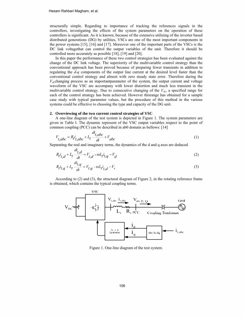
structurally simple. Regarding to importance of tracking the references signals in the controllers, investigating the effects of the system parameters on the operation of these controllers is significant. As it is known, because of the extensive utilizing of the inverter based distributed generations (DG) by utilities, VSCs are one of the most important components in the power systems [15], [16] and [17]. Moreover one of the important parts of the VSCs is the DC link voltagethat can control the output variables of the unit. Therefore it should be controlled more accurately as possible [18], [19] and [20]. In this paper the performance of these two control strategies has been evaluated against the change of the DC link voltage. The superiority of the multivariable control strategy than the conventional approach has been proved because of preparing fewer transients in addition to regulating the d-q components of the output line current at the desired level faster than the conventional control strategy and almost with zero steady state error. Therefore during the Vdcchanging process as an importantparameter of the system, the output current and voltage waveform of the VSC are accompany with lower distortion and much less transient in the multivariable control strategy. Due to consecutive changing of the Vdc, a specified range for each of the control strategy has been achieved. However thisrange has obtained for a sample case study with typical parameter values, but the procedure of this method in the various systems could be effective to choosing the type and capacity of the DG unit. 2. Overviewing of the two current control strategies of VSC A one-line diagram of the test system is depicted in Figure 1. The system parameters are given in Table I. The dynamic represent of the VSC output variables respect to the point of common coupling (PCC) can be described in ab0 domain as bellows: [14]
,
, ,= + +dit abcV R i L Vt tt abc t abc abcdt
(1)
Separating the real and imaginary terms, the dynamics of the d and q axes are deduced
,
,, , ++ = ω −dit dR i L V L i Vt t t t qt d t d ddt
(2)
,
, , ,−+ = ω − q
dit qR i L V L i Vt t q t t q t t ddt (3)
According to (2) and (3), the structural diagram of Figure 2, in the rotating reference frame is obtained, which contains the typical coupling terms.
Figure 1. One-line diagram of the test system.
tL tR
t,abcV abcV
DCV
diqi
t,abci
t ,abci
Hesam Rahbari Magham, et al.
106
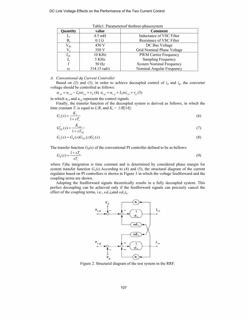
Table1. Parametersof thethree-phasesystem Quantity value Comment
Lt Rt
4.5 mH 0.1Ω
Inductance of VSC Filter Resistance of VSC Filter
Vdc Vs
450 V 350 V
DC Bus Voltage Grid Nominal Phase Voltage
fsw fs f ω
10 KHz 5 KHz 50 Hz
314.15 rad/s
PWM Carrier Frequency Sampling Frequency
System Nominal Frequency Nominal Angular Frequency
A. Conventional dq Current Controller Based on (2) and (3), in order to achieve decoupled control of id and iq, the converter voltage should be controlled as follows:
, , ,= − ω +t d c d t t q du u L i v (4) , , ,= + ω +t q c q t t d qu u L i v (5) in which ucd and ucq represent the control signals. Finally, the transfer function of the decoupled system is derived as follows, in which the time constant Ts is equal to L/R, and Ks = 1/R[14]:
( )
1=
+s
ss
KG s
sT (6)
( )
1=
+s cmPE
PE
KG s
sT (7)
( ) ( ) ( ) ( )=o R PE SG s G s G s G s (8) The transfer function GR(s) of the conventional PI controller defined to be as bellows:
1( )
+= n
Ri
sTG s
sT (9)
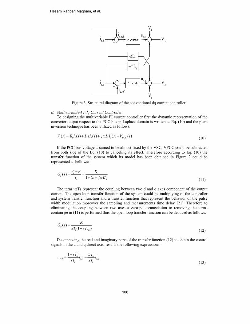
where Tithe integration is time constant and is determined by considered phase margin for system transfer function Go(s).According to (4) and (5), the structural diagram of the current regulator based on PI controllers is shown in Figure 3 in which the voltage feedforward and the coupling terms are shown. Adopting the feedforward signals theoretically results in a fully decoupled system. This perfect decoupling can be achieved only if the feedforward signals can precisely cancel the effect of the coupling terms, i.e., ωLtidand ωLtiq.
Figure 2. Structural diagram of the test system in the RRF.
DC Link Voltage Effects on the Performance of the Two Current Control
107
tL−ω
d,refi
q,refi
t ,di
t ,qi
dV
qV
t,dV
t,qV
tLω
c,du
c,qu
Figure 3. Structural diagram of the conventional dq current controller.
B. Multivariable-PI dq Current Controller To designing the multivariable PI current controller first the dynamic representation of the converter output respect to the PCC bus in Laplace domain is written as Eq. (10) and the plant inversion technique has been utilized as follows.
( ) ( ) ( ) ( ) ( )t t t t t t t PCCV s R I s L sI s j L I s V sω= + + + (10) If the PCC bus voltage assumed to be almost fixed by the VSC, VPCC could be subtracted from both side of the Eq. (10) to canceling its effect. Therefore according to Eq. (10) the transfer function of the system which its model has been obtained in Figure 2 could be represented as bellows:
( )
1 ( )t s
st s
V V KG s
I s j Tω−
= =+ + (11)
The term jωTs represent the coupling between two d and q axes component of the output current. The open loop transfer function of the system could be multiplying of the controller and system transfer function and a transfer function that represent the behavior of the pulse width modulation moreover the sampling and measurements time delay [21]. Therefore to eliminating the coupling between two axes a zero-pole cancelation to removing the terms contain jω in (11) is performed thus the open loop transfer function can be deduced as follows:
( )
(1 )=
+oi PE
KG ssT sT (12)
Decomposing the real and imaginary parts of the transfer function (12) to obtain the control signals in the d and q direct axis, results the following expressions:
, , ,
1ε ε
+ ω= −n n
c d d qi i
sT Tu i i
sT sT (13)
Hesam Rahbari Magham, et al.
108
, , ,
1ε ε
+ ω= +n n
c q q di i
sT Tu i i
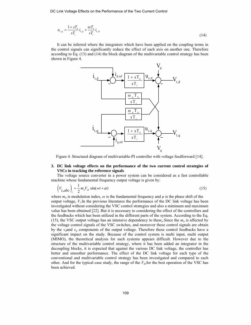
sT sT (14) It can be inferred where the integrators which have been applied on the coupling terms in the control signals can significantly reduce the effect of each axis on another one. Therefore according to Eq. (13) and (14) the block diagram of the multivariable control strategy has been shown in Figure 4.
d,refi
q,refi
t ,di
t ,qi
dV
qV
t,dV
t,qV
n
i
1 s Ts T+
n n
i
Ts T
ω
n n
i
Ts T
ω
n
i
1 s Ts T+
c,du
c,qu
Figure 4. Structural diagram of multivariable-PI controller with voltage feedforward [14].
3. DC link voltage effects on the performance of the two current control strategies of
VSCs in tracking the reference signals The voltage source converter in a power system can be considered as a fast controllable machine whose fundamental frequency output voltage is given by:
( )
1
1 sin( ), 2 a dcV m V wtt abc ϕ= + (15)
where ma is modulation index, ω is the fundamental frequency and φ is the phase shift of the output voltage, Vt.In the previous literatures the performance of the DC link voltage has been investigated without considering the VSC control strategies and also a minimum and maximum value has been obtained [22]. But it is necessary to considering the effect of the controllers and the feedbacks which has been utilized in the different parts of the system. According to the Eq. (15), the VSC output voltage has an intensive dependency to thema.Since the ma is affected by the voltage control signals of the VSC switches, and moreover these control signals are obtain by the vdand vq components of the output voltage. Therefore these control feedbacks have a significant impact on the study. Because of the control system is multi input, multi output (MIMO), the theoretical analysis for such systems appears difficult. However due to the structure of the multivariable control strategy, where it has been added an integrator in the decoupling blocks, it is expected that against the various DC link voltage, the controller has better and smoother performance. The effect of the DC link voltage for each type of the conventional and multivariable control strategy has been investigated and compared to each other. And for the typical case study, the range of the Vdcfor the best operation of the VSC has been achieved.
DC Link Voltage Effects on the Performance of the Two Current Control
109
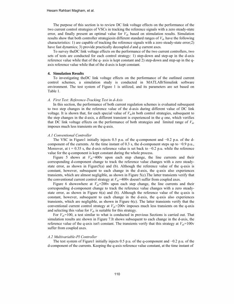
The purpose of this section is to review DC link voltage effects on the performance of the two current control strategies of VSCs in tracking the reference signals with a zero steady-state error, and finally present an optimal value for Vdc based on stimulation results. Simulation results show that both controller strategiesin different standard ranges of Vdc have the following characteristics: 1) are capable of tracking the reference signals with a zero steady-state error;2) have fast dynamics; 3) provide practically decoupled d and q current axes. To survey theDC link voltage effects on the performance of the two current controllers, two sets of tests are conducted for each control strategy: 1) step-down and step-up in the d-axis reference value while that of the q- axis is kept constant and 2) step-down and step-up in the q-axis reference value while that of the d-axis is kept constant. 4. Simulation Results To investigating theDC link voltage effects on the performance of the outlined current control schemes, a simulation study is conducted in MATLAB/Simulink software environment. The test system of Figure 1 is utilized, and its parameters are set based on Table 1. A. First Test: Reference-Tracking Test in d-Axis In this section, the performance of both current regulation schemes is evaluated subsequent to two step changes in the reference value of the d-axis during different value of DC link voltage. It is shown that, for each special value of Vdcin both control strategies, subsequent to the step changes in the d-axis, a different transient is experienced in the q one, which verifies that DC link voltage effects on the performance of both strategies and limited range of Vdc imposes much less transients on the q-axis. A.1 Conventional Controller The VSC in Figure1 initially injects 0.5 p.u. of the q-component and −0.2 p.u. of the d-component of the currents. At the time instant of 0.3 s, the d-component steps up to −0.9 p.u., Moreover, at t = 0.35 s, the d-axis reference value is set back to −0.2 p.u. while the reference value for the q-component is kept constant during the whole process. Figure 5 shows at Vdc=400v upon each step change, the line currents and their corresponding d-component change to track the reference value changes with a zero steady-state error, as shown in Figure5(a) and (b). Although the reference value of the q-axis is constant, however, subsequent to each change in the d-axis, the q-axis also experiences transients, which are almost negligible, as shown in Figure 5(c).The latter transients verify that the conventional current control strategy at Vdc=400v doesn't suffer from coupled axes. Figure 6 showswhere at Vdc=200v upon each step change, the line currents and their corresponding d-component change to track the reference value changes with a zero steady-state error, as shown in Figure 6(a) and (b). Although the reference value of the q-axis is constant, however, subsequent to each change in the d-axis, the q-axis also experiences transients, which are negligible, as shown in Figure 6(c). The latter transients verify that the conventional current control strategy at Vdc=200v imposes much less transients on the q-axis and selecting this value for Vdc is suitable for this strategy. For Vdc=100, a test similar to what is conducted in previous Sections is carried out. That simulation results are shown in Figure 7.It shows subsequent to each change in the d-axis, the reference value of the q-axis isn't constant. The transients verify that this strategy at Vdc=100v suffer from coupled axes. A.2 Multivariable-PI Controller The test system of Figure1 initially injects 0.5 p.u. of the q-component and −0.2 p.u. of the d-component of the currents. Keeping the q-axis reference value constant, at the time instant of
Hesam Rahbari Magham, et al.
110
(a)
(b)
(c)
Figure 5. Simulation results of the transient response of the conventional controller during step
changes in d-axis at Vdc=400V. (a) Line currents. (b) d-component of the currents. (c) q-components of the currents.
(a)
(b)
(c)
Figure 6. Simulation results of the transient response of the conventional controller during step
changes in d-axis at Vdc=200V. (a) Line currents. (b) d-component of the currents. (c) q-components of the currents.
-1
-0.5
0
0.5
1
Iabc
(pu)
IaIbIc
-0.8
-0.6
-0.4
-0.2
0
Id(p
u)
IdrefId
1.45 1.55 1.65 1.75 1.85x 10⁵
0.3
0.5
0.7
Time(sec)
Iq(p
u)
IqrefIq
-1
-0.5
0
0.5
1
Iabc
(pu)
IaIbIc
-0.8
-0.6
-0.4
-0.2
0
Id(p
u)
idrefid
1.45 1.55 1.65 1.75 1.85x 10⁵
0.3
0.4
0.5
0.6
0.7
Time(sec)
Iq(p
u)
IqrefIq
DC Link Voltage Effects on the Performance of the Two Current Control
111

(a)
(b)
(c)
Figure 7. Simulation results of the transient response of the conventional controller during step
changes in d-axis at Vdc=100V. (a) Line currents. (b) d-component of the currents. (c) q-components of the currents.
(a)
(b)
(c)
Figure 8. Simulation results of the transient response of the multivariable-PI controller during step changes in d-axis at Vdc=700V. (a) Line currents. (b) d-component of the currents. (c) q-
components of the currents.
-1
-0.5
0
0.5
1
1.5
Iabc
(pu)
IaIbIc
-0.9
-0.5
-0.2
Id(p
u)
IdrefId
1.45 1.55 1.65 1.75 1.85x 10⁵
0.3
0.5
0.7
Time(sec)
Iq(p
u)
IqrfIq
-5
0
5
10
Iabc
(pu)
IaIbIc
0
4
8
Id(p
u)
IdrefId
1.45 1.55 1.65 1.75 1.85x 10⁵
0.3
0.5
0.7
Time(sec)
Iq(p
u)
IqrefIq
Hesam Rahbari Magham, et al.
112

0.3 s, the d-component steps up to −0.9 p.u., and at t = 0.35 s, it steps down to −0.2 p.u. Figure 8 depicts at Vdc=700v upon to each change in the d-axis reference value, the controller regulates the currents at the desired level, as shown in Figure 8(a) and Figure 8(b) depicts that, subsequent to each step change in the d-axis, the d-component of the currents is regulated at the desired level with a zero steady state error. However both of them experience unsuitable transients. Subsequent to each change in the d-axis, the q-axis also experiences transients, which are not negligible as shown in Figure 8(c). The latter transients verify that selecting this value for Vdcis not suitable for the multivariable-PI current control strategy. And Figure 9 depicts at Vdc=200v upon each step change in the d-axis, the d-component of the currents is regulated at the desired level with a zero steady-state error, as shown in Figure 9(a) and (b). Subsequent to each change in the d-axis, the q-axis also experiences transients, which are negligible, as shown in Figure 9(c). The latter transients verify that the multivariable-PI current control strategy at Vdc=200v imposes much less transients on the q-axis.
(a)
(b)
(c)
Figure 9. Simulation results of the transient response of the multivariable-PI controller during step changes in d-axis at Vdc=200V. (a) Line currents. (b) d-component of the currents. (c) q-
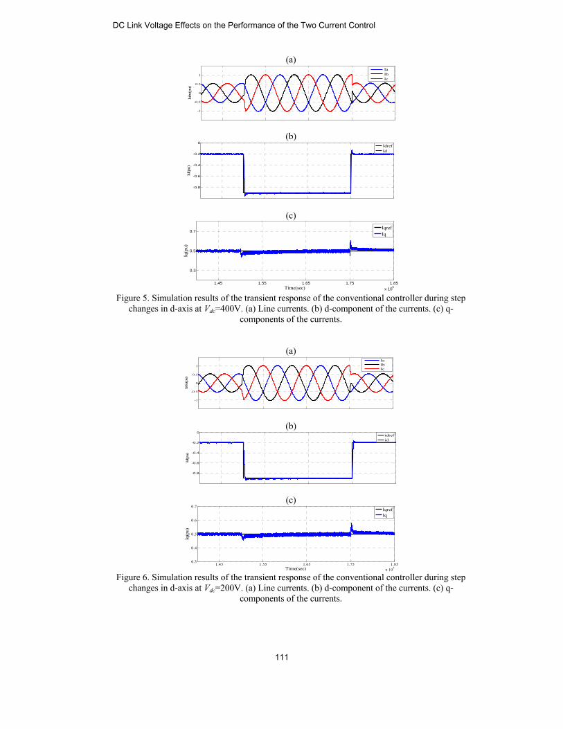
components of the currents. For Vdc=100, a test similar to what is conducted in previous Sections is carried out. That simulation results are shown in Figure 10. It shows this value for Vdcis not suitable for this strategy because subsequent to each change in the d-axis, the reference value of the q-axis isn’t constant.
-1
-0.5
0
0.5
1
1.5
Iabc
(pu)
IaIbIc
-0.9
-0.5
-0.2
0
Id(p
u)
IdrefId
1.45 1.55 1.65 1.75 1.85x 10⁵
0.3
0.5
0.7
Time(sec)
Iq(p
u)
IqrefIq
DC Link Voltage Effects on the Performance of the Two Current Control
113
(a)
(b)
(c)
Figure 10. Simulation results of the transient response of the multivariable-PI controller during step changes in d-axis at Vdc=100V. (a) Line currents. (b) d-component of the currents. (c) q-
components of the currents.
B. Second Test: Reference-Tracking Test in q-Axis In this section, similar to the previous test to reviews DC link voltage effects on the performance of the outlined current control strategies it is shown that, subsequent to the step changes in the q-axis, a transient is experienced in the d one, which verifies that the axes are not fully decoupled. While, this transient is affected by Vdc, and special range of Vdc imposes much less transients on the d-axis. B.1 Conventional Controller The VSC in Figure1 initially injects- 0.5 p.u. of the d-component and −0.2 p.u. of the d-component of the currents. At the time instant of 0.3 s, the q-component steps up to −0.9 p.u., Moreover, at t = 0.35 s, the q-axis reference value is set back to −0.2 p.u. while the reference value for the d-component is kept constant during the whole process. Figure 11 shows at Vdc=400v upon each step change, the line currents and their corresponding q-component change to track the reference value changes with a zero steady-state error, however both of them experience unsuitable transients, as shown in Figure10(a) and (b). Although the reference value of the d-axis isn't constant, as shown in Figure 11(c), this failure to track the reference value verifies that this value for Vdc is not suitable for this controller. Figure 12 shows at Vdc=200v upon each step change, the line currents and their corresponding q-component change to track the reference value changes with a zero steady-state error, as shown in Figure 12(a) and (b). Although the reference value of the d-axis is constant, however, subsequent to each change in the q-axis, the d-axis also experiences transients, which are negligible, as shown in Figure 12(c). The latter transients verify that the conventional current control strategy at Vdc=200v imposes much less transients on the d-axis, and selecting this value for Vdc is suitable for Conventional Controller.
-1
-0.5
0
0.5
1
1.5
Iabc
(pu)
IaIbIc
-0.9
-0.5
-0.2
0
Id(p
u)
IdrefId
1.45 1.55 1.65 1.75 1.85x 10⁵
0.5
0.7
0.9
Time(sec)
Iq(p
u)
IqrefIq
Hesam Rahbari Magham, et al.
114

(a)
(b)
(c)
Figure 11. Simulation results of the transient response of the conventional controller during
step changes in q-axis at Vdc=400V. (a) Line currents. (b) d-component of the currents. (c) q-components of the currents.
(a)
(b)
(c)
Figure 12. Simulation results of the transient response of the conventional controller during
step changes in q-axis at Vdc=200V. (a) Line currents. (b) d-component of the currents. (c) q-components of the currents.
-3
-2
-1
0
1
2
Iabc
(pu)
IaIbIc
-0.5
0
0.5
1
1.5
2
2.5
Id(p
u)
Idref�Id
1.45 1.55 1.65 1.75 1.85x 10⁵
-0.9
-0.5
-0.2
Time(sec)
Iq(p
u)
IqrefIq
-1
-0.5
0
0.5
1
Iabc
(pu)
�
IaIbIc
-0.6
-0.5
-0.4
-0.3
Id(p
u)
IdrefId
1.45 1.55 1.65 1.75 1.85x 10⁵
-0.9
-0.5
-0.2
Time(sec)
Iq(p
u)
IqrefIq
DC Link Voltage Effects on the Performance of the Two Current Control
115
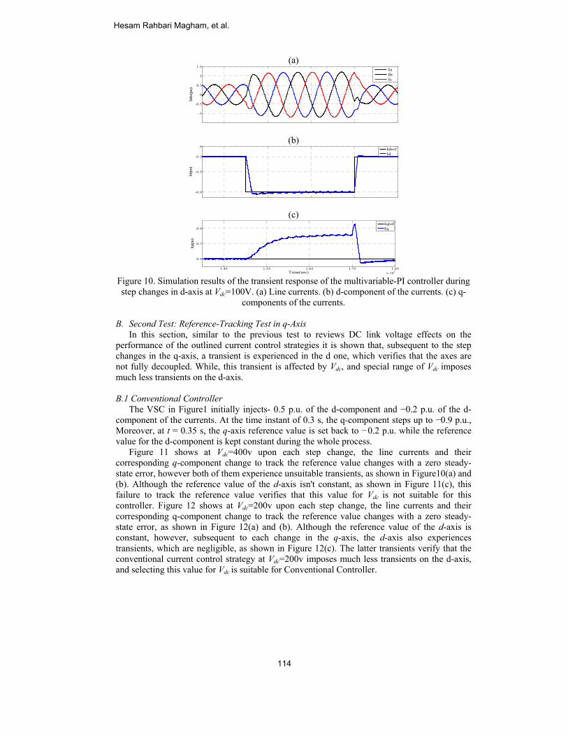
For Vdc=100, a test similar to what is conducted in previous Sections is carried out, that simulation results are shown in Fig 13. Subsequent to each change in the d-axis reference value, the controller regulates the currents at the desired level, as shown in Figure 13(a). Figure 13(b)depicts that, subsequent to each step change in the d-axis, the d-component of the currents isn't regulated at the desired level, this failure to track the reference values verify that this value for Vdc is not suitable for this controller.
(a)
(b)
(c)
Figure 13. Simulation results of the transient response of the conventional controller during
step changes in q-axis at Vdc=100V. (a) Line currents. (b) d-component of the currents. (c) q-components of the currents.
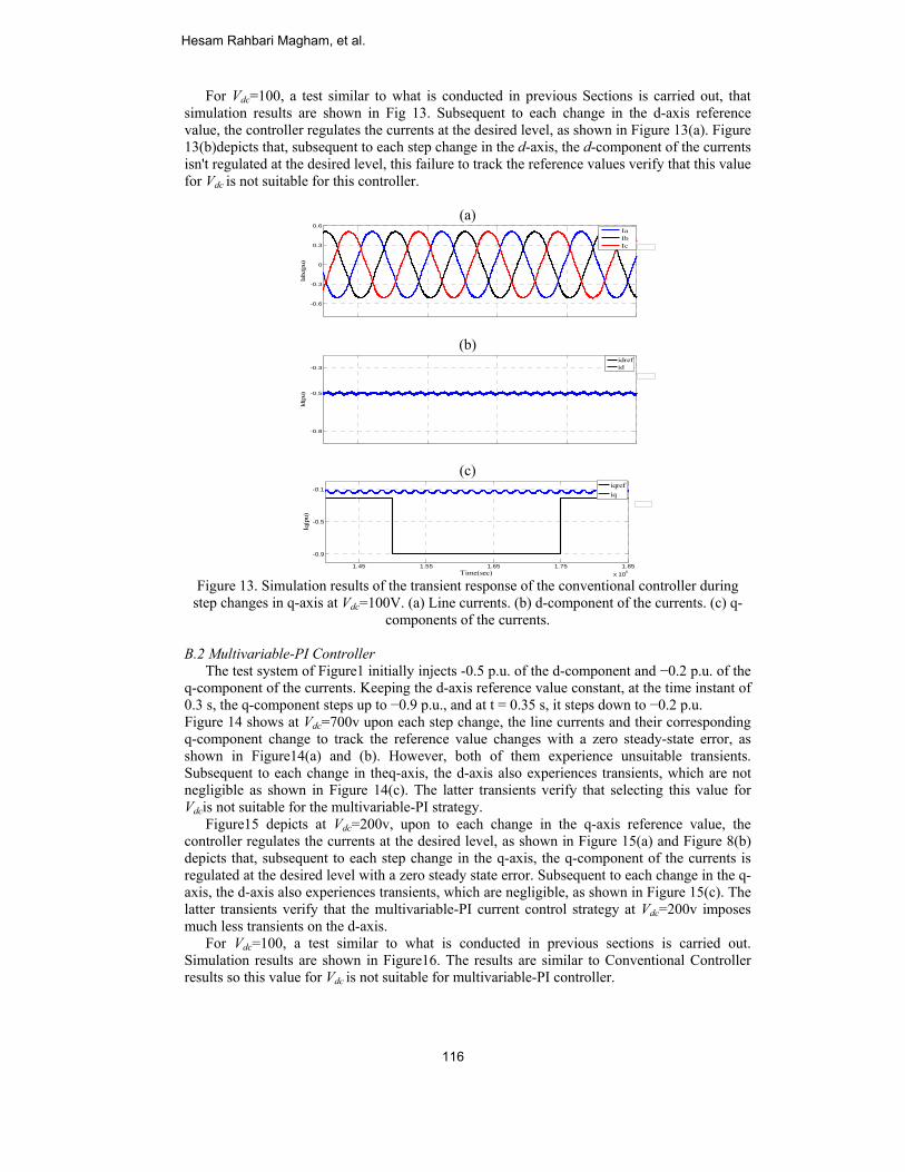
B.2 Multivariable-PI Controller The test system of Figure1 initially injects -0.5 p.u. of the d-component and −0.2 p.u. of the q-component of the currents. Keeping the d-axis reference value constant, at the time instant of 0.3 s, the q-component steps up to −0.9 p.u., and at t = 0.35 s, it steps down to −0.2 p.u. Figure 14 shows at Vdc=700v upon each step change, the line currents and their corresponding q-component change to track the reference value changes with a zero steady-state error, as shown in Figure14(a) and (b). However, both of them experience unsuitable transients. Subsequent to each change in theq-axis, the d-axis also experiences transients, which are not negligible as shown in Figure 14(c). The latter transients verify that selecting this value for Vdcis not suitable for the multivariable-PI strategy. Figure15 depicts at Vdc=200v, upon to each change in the q-axis reference value, the controller regulates the currents at the desired level, as shown in Figure 15(a) and Figure 8(b) depicts that, subsequent to each step change in the q-axis, the q-component of the currents is regulated at the desired level with a zero steady state error. Subsequent to each change in the q-axis, the d-axis also experiences transients, which are negligible, as shown in Figure 15(c). The latter transients verify that the multivariable-PI current control strategy at Vdc=200v imposes much less transients on the d-axis. For Vdc=100, a test similar to what is conducted in previous sections is carried out. Simulation results are shown in Figure16. The results are similar to Conventional Controller results so this value for Vdc is not suitable for multivariable-PI controller.
-0.6
-0.3
0
0.3
0.6
Iabc
(pu)
IaIbIc
-0.8
-0.5
-0.3
Id(p
u)
idrefid
1.45 1.55 1.65 1.75 1.85x 10⁵
-0.9
-0.5
-0.1
Time(sec)
Iq(p
u)
iqrefiq
Hesam Rahbari Magham, et al.
116
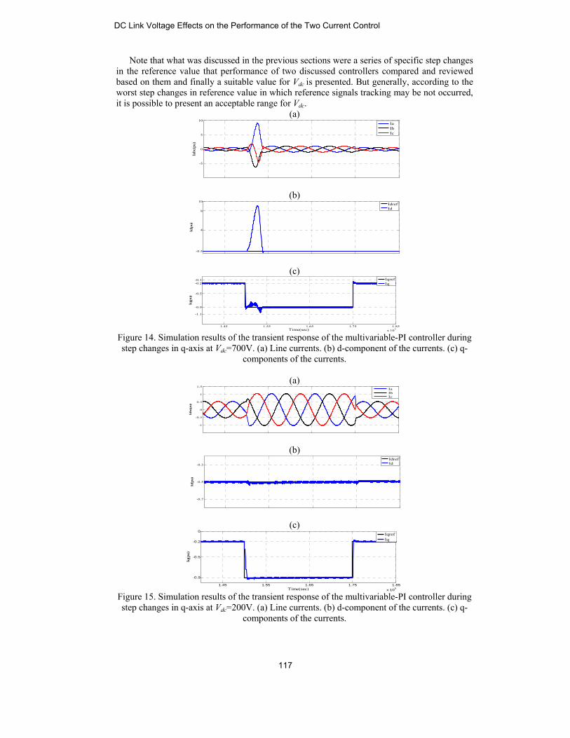
Note that what was discussed in the previous sections were a series of specific step changes in the reference value that performance of two discussed controllers compared and reviewed based on them and finally a suitable value for Vdc is presented. But generally, according to the worst step changes in reference value in which reference signals tracking may be not occurred, it is possible to present an acceptable range for Vdc.
(a)
(b)
(c)
Figure 14. Simulation results of the transient response of the multivariable-PI controller during step changes in q-axis at Vdc=700V. (a) Line currents. (b) d-component of the currents. (c) q-
components of the currents.
(a)
(b)
(c)
Figure 15. Simulation results of the transient response of the multivariable-PI controller during step changes in q-axis at Vdc=200V. (a) Line currents. (b) d-component of the currents. (c) q-
components of the currents.
-5
0
5
10
Iabc
(pu)
IaIbIc
-0.5
4
8
10
Id(p
u)
IdrefId
1.45 1.55 1.65 1.75 1.85x 10⁵
-1.1
-0.9
-0.5
-0.2-0.1
Time(sec)
Iq(p
u)
IqrefIq
-1
-0.5
0
0.5
1
1.5
Iabc
(pu)
IaIbIc
-0.7
-0.5
-0.3
Id(p
u)
IdrefId
1.45 1.55 1.65 1.75 1.85x 10⁵
-0.9
-0.5
-0.2
0
Time(sec)
Iq(p
u)
IqrefIq
DC Link Voltage Effects on the Performance of the Two Current Control
117

(a)
(b)
(c)
Figure 16. Simulation results of the transient response of the multivariable-PI controller during step changes in q-axis at Vdc=100V. (a) Line currents. (b) d-component of the currents. (c) q-
components of the currents.
It could be inferred from simulation results where the multivariable PI controller imposed less transient and more decoupling capability between d and q axis components of the current during the changing process of the Vdc. For example when the q component reference value has been changed, the iq is regulated at the desired value faster than the conventional control strategy and the id experienced much less transient too. In fact as it was expected, the multivariable control strategy has withstand more, respect to the changing the DC link voltage because of the integrator terms which have been used in the decoupling blocks and also eliminating the feed forward signals. According to the boundary quantities which has been considered for the current references signals (id and iq), for both control strategies, an standard range for DC link voltage has been resulted by changing consequently the Vdc. Due to the simulation results and the values of Table I, for the two aforementioned controllers the range follows as:
1. Conventional controller: 150V<Vdc< 200V 2. Multivariable-PI controller: 200V<Vdc< 300V
These values are obtained within the worst step changes in reference signals and for special parameters. Conclusion In this paper the structure of the two conventional and multivariable control strategy has been represented. Due to the importance of the tracking the references signals which have been specified for the controller, the effect of the DC link voltage as one of the most important parameters of the system has been investigated. It has been demonstrated where the multivariable control strategy has less transient and more decoupling capability between d and q axis components of the current during the step changes which have been occurred in the various DC link voltage of the VSC. Finally, based on the considering the worst step changes in the references signals and trying a wide range of the DC link voltage, a particular range has been resulted for it. It has been depicted where if the Vdc is out of this specific range, it will
-0.4
-0.2
0
0.2
0.4
0.6
Iabc
(pu)
IaIbIc
-0.7
-0.5
-0.3
Id(p
u)
IdrefId
1.45 1.55 1.65 1.75 1.85x 10⁵
-1-0.9
-0.5
-0.2
0
Time(sec)
Iq(p
u)
IqrefIq
Hesam Rahbari Magham, et al.
118
either have negative effects on the controller’s performance or causes signal tracking not occur at all which means system is unstable. References [1] S. B. Kjaer, J. K. Pedersen, and F. Blaabjerg, “A review of single-phase grid-connected
inverters for photovoltaic modules,” IEEE Trans. Ind. Appl., vol. 41, no. 5, pp. 1292–1306, Sep./Oct. 2005.
[2] B. C. Rabelo, W. Hofmann, J. Lucas da Silva, R. Gaiba de Oliveira, and S. R. Silva, “Reactive power control design in doubly fed induction generators for wind turbines,” IEEE Trans. Ind. Electron., vol. 56, no. 10,pp. 4154–4162, Oct. 2009.
[3] H. Akagi, “Active harmonic filters,” Proc. IEEE, vol. 93, no. 12, pp. 2128–2141, Dec. 2005.
[4] M. Sedighy, S. B. Dewan, and F. P. Dawson, “A robust digital current control method for active power filters,” IEEE Trans. Ind. Appl., vol. 36,no. 4, pp. 1158–1164, Jul./Aug. 2000.
[5] P. G. Barbosa, L. G. B. Rolim, and E. H. Watanabe, “Control strategy for grid-connected DC–AC converters with load power factor correction converters,” Proc. Inst. Elect. Eng.—Gener. Transmiss. Distrib., vol. 145,no. 5, pp. 487–491, Sep. 1998.
[6] L. Hassaine, E. Olias, J. Quintero, and M. Haddadi, “Digital power factor control and reactive power regulation for grid-connected photovoltaic inverter,” Renew. Energ., vol. 34, no. 1, pp. 315–321, Jan. 2009.
[7] M. Saeedifard, R. Iravani, and J. Pou, “A space vector modulation strategy for a back-to-back five-level HVDC converter system,” IEEE Trans. Ind. Electron., vol. 56, no. 2, pp. 452–466, Feb. 2009.
[8] S. Buso, S. Fasolo, L. Malesani, and P. Mattavelli, “A dead-beat adaptive hysteresis current control,” IEEE Trans. Ind. Appl., vol. 36, no. 4,pp. 1174–1180, Jul./Aug. 2000.
[9] D. N. Zmood and D. G. Holmes, “Stationary frame current regulation of PWM inverters with zero steady-state error,” IEEE Trans. Power Electron., vol. 18, no. 3, pp. 814–822, May 2003.
[10] D. N. Zmood, D. G. Holmes, and G. H. Bode, “Frequency-domain analysis of three-phase linear current regulators,” IEEE Trans. Ind. Appl., vol. 37, no. 2, pp. 601–610, Mar/Apr. 2001.
[11] C. Schauder and H. Mehta, “Vector analysis and control of advanced static VAR compensators,” Proc. Inst. Elect. Eng.—Gener. Transmiss. Distrib., vol. 140, no. 4, pp. 299–306, Jul. 1993.
[12] M. P. Kazmierkowski and L. Malesani, “Current control techniques for three-phase voltage-source PWM converters: A survey,” IEEE Trans. Ind. Electron., vol. 45, no. 5, pp. 691–703, Oct. 1998.
[13] E. Twining and D. G. Holmes, “Grid current regulation of a three-phase voltage source inverter with an LCL input filter,” IEEE Trans. Power Electron., vol. 18, no. 3, pp. 888–895, May 2003.
[14] B. Bahrani, S.Kenzelmann and A. Rufer, “Multivariable-PI-based dq current control of voltage source converters with superior axis decoupling capability,” IEEE Trans. Ind. Electron., vol. 58,no. 7, pp. 3016–3026, Jul. 2011.
[15] A. Sato and T. Noguchi, “Voltage-source PWM rectifier–inverter based on direct power control and its operation characteristics,” IEEE Trans. Power Electron., vol. 26, no. 5, pp. 1559–1567, May 2011.
[16] F. Schettler, H. Huang and N. Christl, “HVDC transmission systems using voltage sourced converters - design and applications”, IEEE Summer Power Meeting, July 2000, Vol.2, pp 715-720.
[17] P. H. Divshali, A. Alimardani, S.H. Hosseinian, M. Abedi, “Decentralized cooperative control strategy of microsources for stabilizing autonomous VSC-based microgrids,” IEEE Trans. Power Systems., vol. 27, no. 4, pp. 1949 - 1959, Nov. 2012.
DC Link Voltage Effects on the Performance of the Two Current Control
119

[18] O. E
contpp. 4
[19] T. LstratDeli
[20] X. Yfull Pow
[21] H. BLaus
[22] C. BJan.
current rsystem m
Ellabban, J. Vtrol strategy of4088 - 4097, SL. Vandoorn, tegy for islandivery., vol. 26, Yuan, F. Wang
power converwer Electron., vBühler, Réglagsanne, Switzer
Bajracharya, “C2008.
HesamEngin2011.CUnivesystemmicro-
ErfanNoshithe Mtechnopower
Javadhis B.SLondoLoughhe wasof Tecfrom Bthe Am
esearch interemodeling and de
Van Mierlo, P. f the Z-source ep. 2012. B. Meersman,ded microgridno. 2, pp. 703
g, D. Boroyevirter for wind gvol. 24, no. 9, pge des Systèmerland: PPUR, PControl of VSC
m Rahbari eering from Currently, he i
ersity of Technm and power tr-grids.
n Ma’ali Amirrvani Babol
M.S. studies iology (Tehran r systems, digit
d Shokrollahi MS. and M.S. in on, England hborough, Engls with the Depchnology, TehrBath Universitymirkabir Univeests include Design using FEM
Lataire, “A Dinverter,” IEE
, L. Degrootes with DC-Li- 713, April. 2
ich, Y. Li, andgenerator operpp. 2178–2192es d’ÉlectroniqPresses PolytecC-HVDC for w
Magham obShiraz univer
is an M.Sc studnology, Tehranransformer mo
ri received his university, Irain electrical ePolytechnic),
tal signal proce
Moghani wasElectrical Engand the Lou
land, in 1982 apartment of Eleran, Iran. He rey, Bath, Englanersity of Techn
DC-DC converM.
DSP-based duaEE Trans. Pow
, B. Renders, ink voltage co2011. d R. Burgos, “Drating inweak-, Sep. 2009.
que de Puissanhniques et Uni
wind power”, Sp
btained his Brsity of techndent in Electric, Iran. His rese
onitoring, HVD
B.S. degree inan, in 2011.He engineering inTehran, Iran.
essing, micro-g
s born in Tabrigineering from ughborough Uand 1984, respectrical Engineeceived his Phnd, in 1995. Afnology where rters, electric
al-loop peak Dwer Electron.,
L. Vandeveldontrol,” IEEE
DC-link voltag-grid systems,”
nce, vol. 1, 2 aiversitaires Rompecialization p
B.Sc degree nology of Shcal Engineeringearch interests DC transmissio
n electrical engis currently w
n Amirkabir His research grids.
iz, Iran, in 195the South Ban
University ofpectively. Fromeering, Amirka.D. in Electricfter graduatinghe has been edrives and el
C-link voltagevol. 27, no. 9,
de, “A controlTrans. Power
ge control of a” IEEE Trans.
and 3, Théorie.mandes, 1997.
project, NTNU,
in Electricalhiraz, Iran ing at Amirkabirinclude power
on systems and
gineering fromworking toward
University ofis focused on
6. He receivednk Polytechnic,f Technology,
m 1984 to 1991abir Universityal Engineering
g he returned toever since. Hislectromagnetic
e ,
l r
a .
. ,
l n r r d
m d f n
d , ,
1 y g o s c
Hesam Rahbari Magham, et al.
120
drives.
Associatethe ministAssociatiowas awar650 journand transf
BabakdegreeHormAmirkwheremembresearpower
G. B.engineAmirkUniveAs a AcadeVoltagthe A
e Professor fromtry of higher eon of Electrica
rded the Nationnal and conferformers transie
k Abdi (S’07)e in electricaozgan, Iran, inkabir Universite he is currenber of Islamicrch interests ir electronics, e
Gharehpetiaeering in 1987kabir Universiersity, Tehran,
Ph.D. studenemic Exchangge Institute of ssistant Profesm 2004 to 200education as thal and Electronnal Prize in 200ence papers. Hents and power
) was born in Tal engineering
n 2002, and thety of Technolo
ntly working toc Azad Univnclude powerlectromagnetic
an received his, 1989 and 199ity of TechnoIran, respectiv
nt, he has rece Service) froRWTH Aache
ssor position at07 and has beenhe distinguishenics Engineers)08 and 2010, rHis teaching anr electronics ap
Tehran, Iran, ing from the e M.S. degree iogy (Tehran Pooward the Ph
versity, Damavr electronics, c interferences
s BS, MS and96 from Tabrizology (AUT),
vely, graduatingeived scholars
om 1993 to 1en, Aachen, Get AUT from 1n Professor sind professor of ) as the distingurespectively. Hnd research in
pplications in p
n 1976. He recUniversity ofn electrical engolytechnic), Te.D. degree. Hvand Branch,application of, and electrical
d Ph.D. degreez University, T, Tehran, Irang all with Firstship from DA996 and he w
ermany. He ha997 to 2003, t
nce 2007. He wf Iran and by IAuished researchHe is the authonterest include power systems.
ceived the B.Sf Hormozgan,gineering fromehran, in 2005,
He is a faculty Tehran. His
f reliability inl machines and
es in electricalTabriz, Iran andn and Tehrant Class HonorsAAD (Germanwas with Highas been holdingthe position of
was selected byAEEE (Iranianher of Iran and
or of more thanpower system
. ,
m ,
y s n d
l d n .
n h g f y n d n
m
DC Link Voltage Effects on the Performance of the Two Current Control
121


