Date: 2007 February - TC 7.6tc76.org/spc100/docs/IBP 18599/18599-6.pdf · Date: 2007 February DIN V...
91
Date: 2007 February DIN V 18599-6 Energy efficiency of buildings — Calculation of the energy needs, delivered energy and primary energy for heating, cooling, ventilation, domestic hot water and lighting — Part 6: Delivered energy for ventilation systems and air heating systems for residential buildings Energetische Bewertung von Gebäuden — Berechnung des Nutz-, End- und Primärenergiebedarfs für Heizung, Kühlung, Lüftung, Trinkwarmwasser und Beleuchtung — Teil 6: Endenergiebedarf von Wohnungslüftungsanlagen und Luftheizungsanlagen für den Wohnungsbau Supersedes DIN V 18599-6:2005-07
Transcript of Date: 2007 February - TC 7.6tc76.org/spc100/docs/IBP 18599/18599-6.pdf · Date: 2007 February DIN V...

Date: 2007 February
DIN V 18599-6
Energy efficiency of buildings — Calculation of the energy needs, delivered energy and primary energy for heating, cooling, ventilation, domestic hot water and lighting — Part 6: Delivered energy for ventilation systems and air heating systems for residential buildings
Energetische Bewertung von Gebäuden — Berechnung des Nutz-, End- und Primärenergiebedarfs für Heizung, Kühlung, Lüftung, Trinkwarmwasser und Beleuchtung — Teil 6: Endenergiebedarf von Wohnungslüftungsanlagen und Luftheizungsanlagen für den Wohnungsbau
Supersedes DIN V 18599-6:2005-07

DIN V 18599-6:2007-02
2
Contents Page
Foreword..............................................................................................................................................................6 Introduction .........................................................................................................................................................8 1 Scope ......................................................................................................................................................9 2 Normative references ......................................................................................................................... 11 3 Terms, definitions and units.............................................................................................................. 13 3.1 Terms and definitions ........................................................................................................................ 13 3.2 Symbols, units and subscripts.......................................................................................................... 18 4 Relationship between the parts of the DIN V 18599 series of prestandards ................................ 21 4.1 Input parameters from other parts of the DIN V 18599 series of prestandards ........................... 22 4.2 Output parameters for other parts of the DIN V 18599 series of prestandards ........................... 22 4.3 Calculation methods .......................................................................................................................... 23 4.3.1 Ventilation heat sinks......................................................................................................................... 23 4.3.2 Heat losses, heat gains, auxiliary energy and generator heat output........................................... 25 4.3.3 Heat generation with combined heating .......................................................................................... 27 5 Energy need for heating..................................................................................................................... 29 5.1 Supply air temperature ϑV,mech ........................................................................................................... 29 5.1.1 Exhaust ventilation systems ............................................................................................................. 29 5.1.1.1 Exhaust ventilation systems without heat recovery....................................................................... 29 5.1.1.2 Extract air/water heat pump............................................................................................................... 30 5.1.2 Supply and exhaust ventilation systems ......................................................................................... 30 5.1.2.1 Supply and exhaust ventilation systems without heat recovery................................................... 30 5.1.2.2 Extract air/supply air heat exchangers............................................................................................. 30 5.1.2.3 Extract air/supply air heat pumps..................................................................................................... 33 5.1.2.4 Extract air/water heat pumps............................................................................................................. 33 5.1.2.5 Extract air/supply air/water heat pumps .......................................................................................... 34 5.1.3 Air heating systems............................................................................................................................ 34 5.2 Mean ventilation system-driven air change rate nmech ..................................................................... 34 5.2.1 Exhaust ventilation systems ............................................................................................................. 34 5.2.2 Supply and exhaust ventilation systems ......................................................................................... 35 5.2.3 Air heating systems............................................................................................................................ 36 6 Control and emission ......................................................................................................................... 37 6.1 General................................................................................................................................................. 37 6.2 Heat losses Qrv,ce ................................................................................................................................. 37 6.3 Auxiliary energy Qrv,ce,aux..................................................................................................................... 40 7 Distribution.......................................................................................................................................... 41 7.1 General................................................................................................................................................. 41 7.2 Heat losses Qrv,d and uncontrolled heat gains Ql,rv,d ........................................................................ 41 7.3 Auxiliary energy Qrv,d,aux ..................................................................................................................... 45 8 Storage................................................................................................................................................. 46 8.1 General................................................................................................................................................. 46 8.2 Heat losses Qrv,s and uncontrolled heat gains QI,rv,s......................................................................... 46 8.3 Auxiliary energy Qrv,s,aux ...................................................................................................................... 48 9 Generation ........................................................................................................................................... 48 9.1 General................................................................................................................................................. 48 9.2 Heat losses Qrv,g and uncontrolled heat gains QI,rv,g ........................................................................ 49 9.3 Auxiliary energy Qrv,g,aux ...................................................................................................................... 51

DIN V 18599-6:2007-02
3
9.4 Generator heat output Qrv,outg ..........................................................................................................57 9.4.1 Exhaust ventilation systems ..............................................................................................................57 9.4.1.1 Without heat recovery.........................................................................................................................57 9.4.1.2 Extract air/water heat pump ...............................................................................................................57 9.4.2 Supply and exhaust ventilation systems..........................................................................................62 9.4.2.1 Supply and exhaust ventilation systems without heat recovery ...................................................62 9.4.2.2 Extract air/supply air heat exchangers .............................................................................................63 9.4.2.3 Extract air/supply air heat pumps......................................................................................................63 9.4.2.4 Extract air/water heat pump ...............................................................................................................68 9.4.2.5 Extract air/supply air/water heat pump .............................................................................................72 9.4.3 Air heating systems ............................................................................................................................73 9.5 Heat input Qrv,reg due to heat recovered from extract air .................................................................75 9.5.1 Exhaust ventilation systems ..............................................................................................................75 9.5.1.1 Exhaust ventilation systems without heat recovery........................................................................75 9.5.1.2 Extract air/water heat pump ...............................................................................................................75 9.5.2 Supply and exhaust ventilation systems..........................................................................................76 9.5.2.1 Supply and exhaust ventilation systems without heat recovery ...................................................76 9.5.2.2 Extract air/supply air heat exchangers .............................................................................................76 9.5.2.3 Extract air/supply air heat pump........................................................................................................77 9.5.2.4 Extract air/water heat pump ...............................................................................................................77 9.5.2.5 Extract air/supply air/water heat pump .............................................................................................79 9.5.3 Air heating systems ............................................................................................................................79 Annex A (normative) Ventilation systems......................................................................................................80 A.1 Exhaust ventilation systems ..............................................................................................................80 A.1.1 Exhaust ventilation systems without heat recovery........................................................................80 A.1.2 Exhaust ventilation systems with extract air/water heat pump......................................................82 A.2 Supply and exhaust ventilation systems..........................................................................................83 A.2.1 Supply and exhaust ventilation systems without heat recovery ...................................................83 A.2.2 Supply and exhaust ventilation systems with extract air/supply air heat exchanger..................84 A.2.3 Supply and exhaust ventilation systems with extract air/supply air heat pump, with and
without heat exchanger ......................................................................................................................86 A.2.4 Supply and exhaust ventilation systems with extract air/water heat pump and with heat
exchanger.............................................................................................................................................87 A.2.5 Supply and exhaust ventilation systems with extract air/supply air/water heat pump and
heat exchanger ....................................................................................................................................88 A.3 Air heating systems ............................................................................................................................89 A.3.1 With extract air/supply air heat pump, with and without heat exchanger, without
recirculation .........................................................................................................................................89 A.3.2 With heat exchanger, with recirculation ...........................................................................................90 Bibliography......................................................................................................................................................91
Figures
Figure 1 — Overview of the parts of DIN V 18599...............................................................................................8 Figure 2 — Content and scope of DIN V 18599-6 (schematic diagram)............................................................10 Figure 3 — System overview of ventilation systems for residential buildings in accordance with
DIN 1946-6 ..................................................................................................................................................11 Figure 4 — Subscript system .............................................................................................................................21

DIN V 18599-6:2007-02
4
Figure A.1 — Exhaust ventilation system with single-room fans....................................................................... 80 Figure A.2 — Exhaust ventilation system with central fan................................................................................. 81 Figure A.3 — Exhaust ventilation system with heat pump ................................................................................ 82 Figure A.4 — Supply and exhaust ventilation system without heat recovery.................................................... 83 Figure A.5 — Supply and exhaust ventilation systems with extract air/supply air heat exchanger for a
building ....................................................................................................................................................... 84 Figure A.6 — Supply and exhaust ventilation systems with extract air/supply air heat exchanger for a
single room ................................................................................................................................................. 85 Figure A.7 — Supply and exhaust ventilation systems with extract air/supply air heat pump, (with and
without heat exchanger) ............................................................................................................................. 86 Figure A.8 — Supply and exhaust ventilation systems with extract air/water heat pump and heat
exchanger ................................................................................................................................................... 87 Figure A.9 — Supply and exhaust ventilation systems with extract air/supply air/water heat pump and
heat exchanger........................................................................................................................................... 88 Figure A.10 — Air heating system with extract air/supply air heat pump, with and without heat
exchanger, without recirculation................................................................................................................. 89 Figure A.11 — Air heating system with heat exchanger, with recirculation....................................................... 90
Tables
Table 1 — Symbols (used in all calculations in the DIN V 18599 series of prestandards) ............................... 18 Table 2 — Subscripts (used in all balance calculations in the DIN V 18599 series of prestandards)............... 19 Table 3 — Subscripts (specific to DIN V 18599-6) ............................................................................................ 20 Table 4 — General boundary conditions for determining the overall efficiency ηWÜT,mth................................. 32
Table 5 — Default values for monthly supply air temperature for systems with extract air/supply air heat exchangers without preheating by ground/supply air heat exchangers, constructed after 1999 ............... 33
Table 6 — General boundary conditions for determining the operating time trv,mech........................................ 36
Table 7 — Factors f to be used when determining control and emission heat losses, Qrv,ce ........................... 38
Table 8 — Overall efficiencyηrv,ce for heat control and emission in the room................................................... 39
Table 9 — Rated power Pc of the controller for heat control and emission in the room.................................... 40
Table 10 — Boundary conditions 1 for default values used to determine heat losses Qrv,d ............................. 44
Table 11 — Boundary conditions 2 for default values used to determine heat losses Qrv,d ............................. 45
Table 12 — General boundary conditions for determining the generation heat losses Qrv,g in relation to the type of ventilation system ..................................................................................................................... 50
Table 13 — Default values for determining the heat loss factor fce,mth in relation to the ventilation system components and the location where they are installed .............................................................................. 51
Table 14 — Degree-day values FGt,Vorw of air preheating (in the respective month), in Kh, as a function of the activation temperature of frost-prevention operation........................................................................ 55
Table 15 — General boundary conditions for determining the auxiliary energy for heat generation Qrv,g in relation to the type of ventilation system .................................................................................................... 56
Table 16 — Default values for the volume flow-related fan power consumption Pel,Vent of the fans.................. 57

DIN V 18599-6:2007-02
5
Table 17 — Correction factors fT und fϑ for temperature deviations..................................................................60
Table 18 — Correction factor for air volume flow deviations..............................................................................64 Table 19 — Maximum monthly operating times ton,h,i,max,mth of the extract air/supply air heat pumps in
bins i (in the respective month), in h ...........................................................................................................65 Table 20 — Default values for the volume flow related power consumption and the performance
coefficient of the heat pump ........................................................................................................................68 Table 21 — Default values for determining the monthly generator heat output of the extract air/supply air
heat exchanger in combination with an extract air heat pump....................................................................68

DIN V 18599-6:2007-02
6
Foreword
This prestandard has been prepared by DIN Joint Committee NA 005-56-20 GA Energetische Bewertung von Gebäuden of the Normenausschuss Bauwesen (Building and Civil Engineering Standards Committee), which also lead-managed the work, and Normenausschuss Heiz- und Raumlufttechnik (Heating and Ventilation Standards Committee) with the co-operation of the Normenausschuss Lichttechnik (Lighting Technology Standards Committee).
A prestandard is a standard which cannot be given full status, either because certain reservations still exist as to its content, or because the manner of its preparation deviates in some way from the normal procedure.
No draft of the present prestandard has been published.
Comments on experience with this prestandard should be sent:
⎯ preferably by e-mail containing a table of the data, to [email protected]. A template for this table is provided on the Internet under the URL http://www.din.de/stellungnahme;
⎯ or as hard-copy to Normenausschuss Bauwesen (NABau) im DIN Deutsches Institut für Normung e. V., 10772 Berlin, Germany (office address: Burggrafenstrasse 6, 10787 Berlin, Germany).
The DIN V 18599 series of prestandards Energy efficiency of buildings — Calculation of the energy needs, delivered energy and primary energy for heating, cooling, ventilation, domestic hot water and lighting consists of the following parts:
⎯ Part 1: General balancing procedures, terms and definitions, zoning and evaluation of energy carriers
⎯ Part 2: Energy needs for heating and cooling of building zones
⎯ Part 3: Energy need for air conditioning
⎯ Part 4: Energy need and delivered energy for lighting
⎯ Part 5: Delivered energy for heating systems
⎯ Part 6: Delivered energy for ventilation systems and air heating systems for residential buildings
⎯ Part 7: Delivered energy for air handling and air conditioning systems for non-residential buildings
⎯ Part 8: Energy need and delivered energy for domestic hot water systems
⎯ Part 9: Delivered and primary energy for combined heat and power plants
⎯ Part 10: Boundary conditions of use, climatic data
The DIN V 18599 series of prestandards provides a methodology for assessing the overall energy efficiency of buildings. The calculations enable all energy quantities required for the purpose of heating, domestic hot water heating, ventilation, air conditioning and lighting of buildings to be assessed.

DIN V 18599-6:2007-02
7
In the described procedures, the DIN V 18599 series of prestandards also takes into account the interactive effects of energy flows and points out the related consequences for planning work. In addition to the calculation procedures, the use- and operation-related boundary conditions for an unbiased assessment (i.e. independent of the behaviour of individual users and of the local climatic data) to determine the energy needs are specified.
The DIN V 18599 series of prestandards is suitable for determining the long-term energy needs of buildings or parts of buildings as well as for assessing the possible use of regenerative sources of energy in buildings. The procedure is designed both for buildings yet to be constructed and for existing buildings, and for retrofit measures for existing buildings.
.
Amendments
This prestandard differs from DIN V 18599-6:2005-07 in that it has been revised in form and content.
Previous edition
DIN V 18599-6: 2005-07

DIN V 18599-6:2007-02
8
Introduction
When an energy balance is calculated in accordance with the DIN V 18599 series of prestandards, an integrative approach is taken, i.e. the building, the use of the building and the building’s technical installations and equipment are assessed together, taking the interaction of these factors into consideration. In order to provide a clearer structure, the DIN V 18599 series of prestandards is divided into several parts, each having a particular focus. Figure 1 provides an overview of the topics dealt with in the individual parts of the series.
Figure 1 — Overview of the parts of DIN V 18599

DIN V 18599-6:2007-02
9
1 Scope
The DIN V 18599 series of prestandards provides a method of calculating the overall energy balance of buildings. The described algorithm is applicable to the calculation of energy balances for:
⎯ residential buildings and non-residential buildings;
⎯ planned or new building constructions and existing buildings.
The procedure for calculating the balances is suitable for:
⎯ balancing the energy use of buildings with partially pre-determined boundary conditions;
⎯ balancing the energy use of buildings with freely selectable boundary conditions from the general engineering aspect, e.g. with the objective of achieving a good comparison between calculated and measured energy ratings.
The balance calculations take into account the energy use for:
⎯ heating,
⎯ ventilation,
⎯ air conditioning (including cooling and humidification),
⎯ heating the domestic hot water supply, and
⎯ lighting
of buildings, including the additional electrical power input (auxiliary energy) which is directly related to the energy supply.
This document describes a method of calculating the values for ventilation and air heating systems of residential buildings.
This document describes the energy use of ventilation systems and air heating systems for residential buildings in conjunction with individual subsystems (control and emission, distribution, storage and generation). For this purpose, both the heat losses and the auxiliary energy of the individual subsystems are determined and, provided that these occur within the heated zone, are made available for the subsequent calculations described in DIN V 18599-1 and DIN V 18599-2.
It is also possible to determine the use of subsystems for heat delivery to DIN V 18599-5 and DIN V 18599-8 and vice-versa. In such cases, the initial output data from DIN V 18599-1 and DIN V 18599-2, while the boundary conditions are obtained from DIN V 18599-10. It is also possible to calculate the energy balances of several building zones in which there are more than one units to be balanced.
Figure 2 shows the scope of the present document as a diagram. For the reader’s orientation, all other parts of the DIN V 18599 series of prestandards contain an illustration similar to Figure 2 as shown here, and in which the respective energy components dealt with are shown in colour.

DIN V 18599-6:2007-02
10
Figure 2 — Content and scope of DIN V 18599-6 (schematic diagram)
The required energy use can be calculated using either the methods described in clauses 6 to 9 or by other methods (e.g. DIN V 4701-10, DIN V 4701-12 and PAS 1027), provided these alternative methods deliver equivalent results under comparable boundary conditions (see DIN V 18599-10). The assumptions and boundary conditions on which these calculations are based shall be recorded systematically and shall apply to the total annual heating need Qh,b.
It is assumed that all system components have been designed according to the current rules of technology. The energy need values calculated using this procedure cannot be used to size individual components.
Mechanical ventilation systems for residential buildings are classified into groups in accordance with DIN 1946-6 (see Figure 3). It is assumed that these systems are being operated as intended and in keeping with accepted best practice. Special guidance (e.g. in the planning and design of ventilation systems for residential buildings) is given in DIN 1946-6.

DIN V 18599-6:2007-02
11
Figure 3 — System overview of ventilation systems for residential buildings in accordance with DIN 1946-6
The combination of the ventilation system or air heating system of a residential building with other systems such as heating systems as described in DIN V 18599-5 or domestic hot water systems as described in DIN V 18599-8 is considered, and the respective balances can be calculated.
If the building contains ventilation and air heating systems which are not described in this document, other physically sound algorithms may be used for the assessments, taking this document as a basis.
This document does not include descriptions of systems for cooling and air conditioning of residential buildings nor of ventilation systems for non-residential buildings. These systems are described in DIN V 18599-7.
2 Normative references
The following referenced documents are indispensable for the application of this document. For dated references, only the edition cited applies. For undated references, the latest edition of the referenced document (including any amendments) applies.
DIN V 18599-1, Energy efficiency of buildings — Calculation of the energy needs, delivered energy and primary energy for heating, cooling, ventilation, domestic hot water and lighting — Part 1: General balancing procedures, terms and definitions, zoning and evaluation of energy carriers
DIN V 18599-2, Energy efficiency of buildings — Calculation of the energy needs, delivered energy and primary energy use for heating, cooling, ventilation, domestic hot water and lighting — Part 2: Energy needs for heating and cooling of building zones
DIN V 18599-3, Energy efficiency of buildings — Calculation of the energy needs, delivered energy and primary energy for heating, cooling, ventilation, domestic hot water and lighting — Part 3: Energy need for air conditioning
DIN V 18599-4, Energy efficiency of buildings — Calculation of the energy needs, delivered energy and primary energy for heating, cooling, ventilation, domestic hot water and lighting — Part 4: Energy need and delivered energy for lighting

DIN V 18599-6:2007-02
12
DIN V 18599-5, Energy efficiency of buildings — Calculation of the energy needs, delivered energy and primary energy for heating, cooling, ventilation, domestic hot water and lighting — Part 5: Delivered energy for heating systems
DIN V 18599-7, Energy efficiency of buildings — Calculation of the energy needs, delivered energy and primary energy for heating, cooling, ventilation, domestic hot water and lighting — Part 7: Delivered energy for air handling and air conditioning systems for non-residential buildings
DIN V 18599-8:2005-07, Energy efficiency of buildings — Calculation of the energy needs, delivered energy and primary energy for heating, cooling, ventilation, domestic hot water and lighting — Part 8: Energy need and delivered energy for domestic hot water systems
DIN V 18599-9, Energy efficiency of buildings — Calculation of the energy needs, delivered energy and primary energy for heating, cooling, ventilation, domestic hot water and lighting — Part 9: Delivered and primary energy for combined heat and power plants
DIN V 18599-10, Energy efficiency of buildings — Calculation of the energy needs, delivered energy and primary energy for heating, cooling, ventilation, domestic hot water and lighting — Part 10: Boundary conditions of use, climatic data
DIN 1946-6, Ventilation and air conditioning — Part 6: Ventilation for residential buildings — Requirements, performance, acceptance (VDI ventilation code of practice)
DIN 4753-8, Water heaters and water heating installations for drinking water and for service water — Part 8: Thermal insulation for water heaters with nominal capacity up to 1000 l — Requirements and testing
DIN EN 255-3, Air conditioners, liquid chilling packages and heat pumps with electrically driven compressors — Heating mode — Part 3: Testing and requirements for marking for sanitary hot water units
DIN EN 308, Heat exchangers — Test procedures for establishing performance of air to air and flue gases heat recovery devices
DIN V 4701-10, Energy efficiency of heating and ventilation systems in buildings — Part 10: Heating, domestic hot water supply, ventilation
DIN V 4701-12, Energetic evaluation of heating and ventilation systems in existing buildings — Part 12: Heat generation and domestic hot water generation
DIN EN 13141-7, Ventilation for buildings — Performance testing of components/products for residential ventilation — Part 7: Performance testing of mechanical supply and exhaust ventilation units (including heat recovery) for mechanical ventilation systems intended for single family dwellings
DIN EN 13141-8, Ventilation for buildings — Performance testing of components/products for residential ventilation — Part 8: Performance testing of unducted mechanical supply and exhaust ventilation units (including heat recovery) for mechanical ventilation systems intended for a single room
DIN EN 14511-2, Air conditioners, liquid chilling packages and heat pumps with electrically driven compressors for space heating and cooling — Part 2: Test conditions
DIN EN 14511-3, Air conditioners, liquid chilling packages and heat pumps with electrically driven compressors for space heating and cooling — Part 3: Test methods
PAS 1027, Energy efficiency of heating and ventilation systems in existing buildings
ISO 13600, Technical energy systems — Basic concepts
Energieeinsparverordnung (EnEV) (German Energy Saving Ordinance) 2002/2004

DIN V 18599-6:2007-02
13
3 Terms, definitions and units
3.1 Terms and definitions
For the purposes of this document, the following terms and definitions apply.
3.1.1 primary energy calculated quantity of energy, taking into account the energy required outside of the building by the preceding process chains for obtaining, converting and distributing the respective fuels used, in addition to the energy content of the required fuel and the auxiliary energy for the technical building installations
3.1.2 delivered energy (“energy use” in this document) calculated quantity of energy delivered to the technical building installations (heating system, ventilation and air conditioning system, domestic hot water system, lighting system) in order to ensure the specified room temperature, heat the domestic hot water and ensure the desired lighting quality throughout the year
NOTE This energy includes the auxiliary energy required to operate the technical building installations. The delivered energy is transferred at the “interface” constituted by the external building envelope and thus represents the amount of energy which the consumer requires in order to use the building for its intended purpose under standardized boundary conditions. Against this background, the energy use is expressed individually for each energy carrier.
3.1.3 energy needs collective term for the energy needs for heating, cooling, domestic hot water, lighting and humidification
3.1.4 energy need for heating calculated heat energy required in order to maintain the specified thermal room conditions within a building zone during the heating period
3.1.5 energy need for cooling calculated cooling energy required in order to maintain the specified thermal room conditions within a building zone during periods in which the sources of heat generate more energy than is required
3.1.6 energy need for lighting calculated energy required to illuminate a building zone with the quality of lighting specified in the usage profile
3.1.7 energy need for domestic hot water calculated energy required to supply a building zone with the amount of domestic hot water at the required supply temperature specified in the usage profile
3.1.8 energy carrier substance or phenomenon that can be used to produce mechanical work, radiation or heat or to operate chemical or physical processes
3.1.9 energy efficiency (energy performance) evaluation of the energy quality of buildings by comparing calculated energy ratings against standard energy ratings (i.e. with economically viable energy ratings from comparable new or renovated buildings) or by

DIN V 18599-6:2007-02
14
comparing measured energy ratings against comparable values (i.e. with mean measured energy ratings from buildings with comparable types of usage)
3.1.10 conditioning generation of defined conditions in spaces due to heating, cooling, ventilation, humidification, lighting and domestic hot water supply
NOTE Conditioning aims to meet requirements relating to the room temperature, fresh air supply, light, humidity and/or domestic hot water.
3.1.11 conditioned space space and/or enclosure which is heated and/or cooled to a defined set-point temperature and/or humidified and/or illuminated and/or provided with ventilation and/or domestic hot water
NOTE Zones are conditioned spaces having at least one mode of conditioning. Spaces which have no form of conditioning are called “unconditioned spaces”.
3.1.12 zone basic unit of space for calculating energy balances
NOTE 1 A zone is a cumulative term for a section of the floor area or certain part of a building having uniform boundary conditions of use and which does not exhibit any relevant differences in the mode of conditioning and other zone criteria.
NOTE 2 DIN V 18599-10 contains a compilation of boundary conditions of use.
3.1.13 serviced area area comprising all those parts of a building which are served by the same technical building system
NOTE A serviced area (heating, domestic hot water, ventilation, cooling, lighting etc.) can cover several zones; a single zone may also include more than one serviced area.
In keeping with the rules for calculating individual part-balances, it may be necessary to determine the energy use of an individual serviced area. The energy values determined for the serviced area are then distributed over the individual building zones as explained in DIN V 18599-1.
3.1.14 building services technical building systems providing internal climate condition services
NOTE 1 This document deals with heating, cooling, domestic hot water supply, ventilation, humidification and lighting. A building service may include more than one technical building system.
NOTE 2 For example, the “domestic hot water supply” service includes both central and decentralized systems. Appropriate part-balances are assigned to each of the building services.
3.1.15 system boundary outer delimitation of a zone
NOTE Rules for determining system boundaries are described in DIN V 18599-1.
3.1.16 envelope or thermal envelope area outer delimitation of any zone

DIN V 18599-6:2007-02
15
NOTE 1 The envelope or thermal envelope area is the boundary between conditioned spaces and the external air, the ground or unconditioned spaces. The cooled or heated spaces will lose heat or gain heat via this surface and, for this reason, it can be also called the “thermal envelope area”. Spaces which are not heated or cooled, but which have other forms of conditioning (e.g. lighting, ventilation) also have specific envelopes, but these do not contribute to heat transfer. For simplification, the designations “envelope” and “thermal envelope area” are used synonymously.
NOTE 2 The envelope or thermal envelope area is formed by a material boundary, usually by the outer facade, internal surfaces, basement ceiling, ceiling of the top storey or by the roof. Rules for delimiting envelopes are described in DIN V 18599-1.
3.1.17 net floor area, reference area usable floor area within the conditioned volume of the building
NOTE The net floor area (ANGF) is used as the reference area.
3.1.18 gross volume, external volume (Ve) volume of a building or of a building zone as calculated on the basis of external dimensions
NOTE 1 This volume includes, at least, all the spaces in a building or zone which are directly or (since they are interconnected) indirectly conditioned as required for their function.
NOTE 2 Rules for determining the gross volume are described in DIN V 18599-1.
3.1.19 net volume, air volume V (internal volume) volume which undergoes air interchange within a conditioned zone or within an entire building
NOTE 1 The net volume is determined on the basis of the internal dimensions, i.e. the volume of the building structure itself is not included.
NOTE 2 The net volume is calculated by multiplying the net floor area by the clear ceiling height. The clear ceiling height is the difference in height between the upper face of the floor and the lower face of the storey floor above or suspended ceiling. As an estimate, (if no internal measurements are taken, for instance) the net volume is calculated using the equation V = 0,8 × Ve, with Ve being the gross volume (external volume).
3.1.20 reference internal temperature mean internal temperature of a building or a building zone on which the calculations of the energy needs for heating and cooling are based. Also the mean temperature based on heating patterns with limited heating in certain sections or at certain times and, where the energy need for cooling is to be calculated, taking into account the permitted temperature variations
NOTE Different temperature values are usually assumed for heating and for cooling, respectively.
3.1.21 external temperature temperature of the external air, which is determined by meteorological measurement and evaluation and is taken as a basis for the calculations
3.1.22 heat sink quantity of heat drawn out of the building zone
NOTE This does not include heat removed by means of the cooling system.

DIN V 18599-6:2007-02
16
3.1.23 heat source quantity of heat with temperatures above the internal temperature, which is fed into the building zone or which is generated inside the building zone
NOTE This does not include controlled heat energy input via the technical systems (heating, ventilation) in order to maintain the set internal temperature.
3.1.24 utilization factor factor by which the total input from the monthly or annually active heat sources is reduced in order to determine the usable portion of the heat from the respective sources
3.1.25 air volume net volume volume subject to air exchange within a zone with thermal conditioning
NOTE It is determined on the basis of the internal dimensions, i.e. the volume of the building structure itself is not included.
3.1.26 air change rate air flow per unit volume
3.1.27 system losses losses (heat losses, cooling losses) occurring in technical subsystems between the energy need and the energy use, i.e. losses occurring due to control and emission, distribution, storage and generation
NOTE Where such system losses occur within the conditioned spaces, they are considered to be part of the heat sources or heat sinks.
3.1.28 renewable energy energy from sources which will not be depleted within the foreseeable existence of the human race (e.g. solar energy (thermal, photovoltaic and for lighting purposes), wind, water and energy from biomass)
3.1.29 calculation period period for which the balance of relevant energy flows in a building is calculated
NOTE The calculation period for calculating the delivered energy and primary energy use is one year; periods of one month or one day can be used for calculating partial energy values.
3.1.30 auxiliary energy energy required by systems for heating, cooling, domestic hot water heating, air conditioning (including ventilation) and lighting in order to support energy transformation to satisfy energy needs
NOTE This includes the energy required by pumps, fans, controls, electronics etc., but not the transformed energy.
3.1.31 energy content amount of thermal energy which is output by complete combustion of a specific quantity of fuel at a constant pressure of 101 320 Pa
NOTE When expressed as the gross calorific value, the energy content includes the latent heat liberated by condensation of water vapour. The net calorific value does not include this latent heat.

DIN V 18599-6:2007-02
17
3.1.32 ventilation system for residential buildings residential ventilation system system for supplying fresh air and/or removing exhaust air which conveys external air into the building, and which may include heat recovery and air conditioning
NOTE Systems for supplying fresh air and/or removing exhaust air may be decentralized systems intended for a single room or central supply and/or exhaust ventilation systems.
3.1.33 air heating system for residential buildings heating system which supplies heat to a zone using only air as the heat carrier
NOTE Air heating systems have at least one heat generator (e.g. a heat pump for extract air heat recovery). In addition, they may include a heat exchanger for heat recovery. Air heating systems can be operated using external air, a combination of external air and recirculated air, or recirculated air only.
3.1.34 control and emission subsystem in which energy is transferred (e.g. to the space or room), while conforming with the specified requirements (particularly with respect to comfort) (see DIN V 18599-10)
3.1.35 distribution subsystem in which the required quantity of energy is transmitted from the generator to the heat control and emission system
3.1.36 storage subsystem in which the heat contained in a medium is stored
NOTE In residential ventilation systems or air heating systems, this may be effected by a buffer storage tank in conjunction with an extract air/water heat pump.
3.1.37 generation subsystem which provides the quantity of heat required by the systems
3.1.38 operating time of ventilation systems for residential buildings time determined on the basis of the daily operating time and the operating time per month
NOTE 1 The operating time per day is expressed in h/d, the operating time per month, in d/month.
NOTE 2 As far as the monthly operating time is concerned, a distinction is made between year-round operation and heating season operation.
NOTE 3 In the case of year-round operation, the residential ventilation system is operated on all days of the year. At times outside the heating season, the air conditioning functions shall bypass any heat recovery system which may be installed; otherwise the heat recovery system shall be shut down outside the heating season.
NOTE 4 In the case of heating season operation, the residential ventilation system is shut down in the summer months (i.e. outside the heating season). By default, the operating time within the heating season is determined from the heating months, i.e. the residential ventilation system is in operation on all days of the heating months; in the following, this method is termed the “heating-months method”. All months for which the energy need for heating has been determined as described in DIN V 18599-2 and in which no ventilation system is used are considered to be heating months.
NOTE 5 As an alternative, the monthly operating time can be determined on the basis of the heating time without ventilation system support as described in DIN V 18599-2. The residential ventilation system is only operated on heating

DIN V 18599-6:2007-02
18
days; in the following, this method is termed the “heating-time method”. If the heating-time method is used in the balance calculations, the residential ventilation system is controlled using a suitable reference variable (e.g. external temperature compensation).
3.1.39 product data manufacturer-specific data on the basis of
— a declaration of conformity to harmonized European specifications or corresponding European directives, or
— a declaration of conformity to generally recognized technical standards, or
— a building-inspectorate certificate of usability
that is suitable for this calculation procedure
3.1.40 default value data which can be used for the calculation if no suitable product data are available for the calculation procedure
3.2 Symbols, units and subscripts
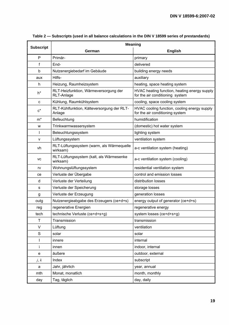
Table 1 contains an overview of important symbols which are generally applicable to the overall balance described in the DIN V 18599 series of prestandards. Table 2 lists the subscripts which are used in all balance calculations. Table 3 lists the additional subscripts specified in the present document.
Table 1 — Symbols (used in all calculations in the DIN V 18599 series of prestandards)
Meaning Symbol
German English Standard unit
f Faktor factor –
Q Energie energy kWh/a
η Nutzungsgrad, Effizienz, Ausnutzung
performance factor, efficiency, utilization factor –
t Zeit, Zeitperiode time, time period, hours h, h/a
A Fläche area m2
V Volumen volume m3
V& Volumenstrom volume flow rate m3/h
Φ Leistung, Energiestrom power, energy flow rate W
Φ Lichtstrom luminous flux lm
Δ Differenz difference –
γ Quellen/Senken-Verhältnis source/sink ratio –
ϑ Celsiustemperatur Celsius temperature °C
DIN V 18599-6:2007-02
19
Table 2 — Subscripts (used in all balance calculations in the DIN V 18599 series of prestandards)
Meaning Subscript
German English
P Primär- primary
f End- delivered
b Nutzenergiebedarf im Gebäude building energy needs
aux Hilfs- auxiliary
h Heizung, Raumheizsystem heating, space heating system
h* RLT-Heizfunktion, Wärmeversorgung der RLT-Anlage
HVAC heating function, heating energy supply for the air conditioning system
c Kühlung, Raumkühlsystem cooling, space cooling system
c* RLT-Kühlfunktion, Kälteversorgung der RLT-Anlage
HVAC cooling function, cooling energy supply for the air conditioning system
m* Befeuchtung humidification
w Trinkwarmwassersystem (domestic) hot water system
l Beleuchtungssystem lighting system
v Lüftungssystem ventilation system
vh RLT-Lüftungssystem (warm, als Wärmequelle wirksam) a-c ventilation system (heating)
vc RLT-Lüftungssystem (kalt, als Wärmesenke wirksam) a-c ventilation system (cooling)
rv Wohnungslüftungssystem residential ventilation system
ce Verluste der Übergabe control and emission losses
d Verluste der Verteilung distribution losses
s Verluste der Speicherung storage losses
g Verluste der Erzeugung generation losses
outg Nutzenergieabgabe des Erzeugers (ce+d+s) energy output of generator (ce+d+s)
reg regenerative Energien regenerative energy
tech technische Verluste (ce+d+s+g) system losses (ce+d+s+g)
T Transmission transmission
V Lüftung ventilation
S solar solar
I innere internal
i innen indoor, internal
e äußere outdoor, external
j, k Index subscript
a Jahr, jährlich year, annual
mth Monat, monatlich month, monthly
day Tag, täglich day, daily

DIN V 18599-6:2007-02
20
Table 3 — Subscripts (specific to DIN V 18599-6)
Meaning Subscript
German English
Energy needs (see clause 5)
mech mechanisch, ventilatorgestützt mechanical, fan-assisted
WRG Wärmerückgewinnung heat recovery
WÜT Wärmeübertrager heat exchanger
Dicht Dichtheit Lüftungsgerät airtightness of ventilation unit
Frost Abtaubetrieb Lüftungsgerät defrost operating mode of ventilation unit
Wärme Wärmeverluste Lüftungsgerät heat losses of ventilation unit
Heat control and emission (see clause 6)
hydr hydraulischer Abgleich hydraulic balance
int intermittierender Betrieb intermittent operation
Radiant Strahlungseinfluss effect of radiation
B Außenbauteile external building components, elements
C Raumtemperaturregelung room temperature control
L Lufttemperaturprofil air temperature profile
Distribution (see clause 7)
a Anordnung Arrangement, sequencing
Vent Ventilator fan
Storage (see clause 8)
B Bereitschaft stand-by
HP Heizperiode heating season
Pumpe Pumpe pump
Verbindung Verbindung connection
Generation (see clause 9)
WP Wärmepumpe heat pump
Vorw Vorwärmer pre-heater
NH Nachheizregister reheating coil
Reg Regelung control
EWÜT Erdreich-Zuluft-Wärmeübertrager ground/supply air heat exchanger
Gt Gradtagsstunden degree-day hours
Figure 4 shows the system of subscripts used for designating the energy quantities in the balances.

DIN V 18599-6:2007-02
21
Figure 4 — Subscript system
4 Relationship between the parts of the DIN V 18599 series of prestandards
The following two subclauses
⎯ summarize the input parameters to be used in this document,
⎯ provide an overview of how the part-balances using the method described here are applied in other parts of the DIN V 18599 series.
For simplification, neither the parameters nor the reasons why data are needed in other calculations are explained here.
The calculation method used in this document is described in 4.3.
DIN V 18599-6:2007-02
22
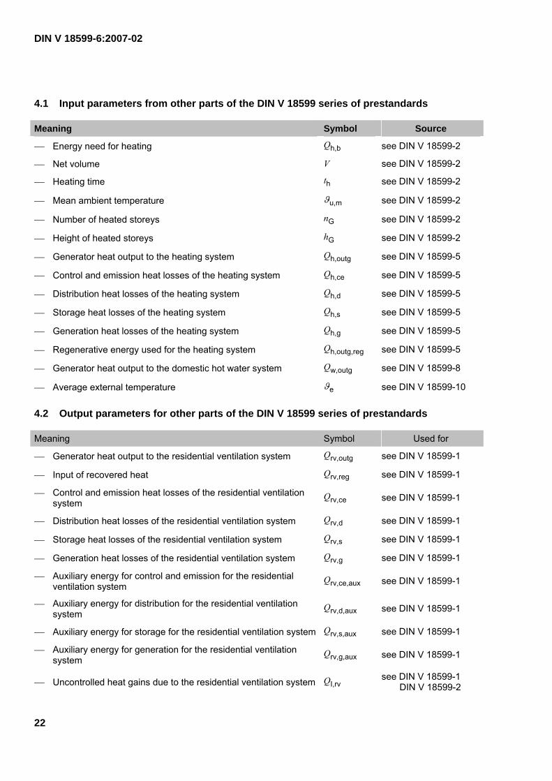
4.1 Input parameters from other parts of the DIN V 18599 series of prestandards
Meaning Symbol Source
⎯ Energy need for heating Qh,b see DIN V 18599-2
⎯ Net volume V see DIN V 18599-2
⎯ Heating time th see DIN V 18599-2
⎯ Mean ambient temperature ϑu,m see DIN V 18599-2
⎯ Number of heated storeys nG see DIN V 18599-2
⎯ Height of heated storeys hG see DIN V 18599-2
⎯ Generator heat output to the heating system Qh,outg see DIN V 18599-5
⎯ Control and emission heat losses of the heating system Qh,ce see DIN V 18599-5
⎯ Distribution heat losses of the heating system Qh,d see DIN V 18599-5
⎯ Storage heat losses of the heating system Qh,s see DIN V 18599-5
⎯ Generation heat losses of the heating system Qh,g see DIN V 18599-5
⎯ Regenerative energy used for the heating system Qh,outg,reg see DIN V 18599-5
⎯ Generator heat output to the domestic hot water system Qw,outg see DIN V 18599-8
⎯ Average external temperature ϑe see DIN V 18599-10
4.2 Output parameters for other parts of the DIN V 18599 series of prestandards
Meaning Symbol Used for
⎯ Generator heat output to the residential ventilation system Qrv,outg see DIN V 18599-1
⎯ Input of recovered heat Qrv,reg see DIN V 18599-1
⎯ Control and emission heat losses of the residential ventilation system
Qrv,ce see DIN V 18599-1
⎯ Distribution heat losses of the residential ventilation system Qrv,d see DIN V 18599-1
⎯ Storage heat losses of the residential ventilation system Qrv,s see DIN V 18599-1
⎯ Generation heat losses of the residential ventilation system Qrv,g see DIN V 18599-1
⎯ Auxiliary energy for control and emission for the residential ventilation system
Qrv,ce,aux see DIN V 18599-1
⎯ Auxiliary energy for distribution for the residential ventilation system
Qrv,d,aux see DIN V 18599-1
⎯ Auxiliary energy for storage for the residential ventilation system Qrv,s,aux see DIN V 18599-1
⎯ Auxiliary energy for generation for the residential ventilation system
Qrv,g,aux see DIN V 18599-1
⎯ Uncontrolled heat gains due to the residential ventilation system QI,rv see DIN V 18599-1 DIN V 18599-2

DIN V 18599-6:2007-02
23
Meaning Symbol Used for
⎯ Uncontrolled cold gains due to the residential ventilation system QI,rv,c see DIN V 18599-1 DIN V 18599-2
⎯ Residual generator heat output for heating Q*h,outg see DIN V 18599-1 DIN V 18599-5
⎯ Residual generator heat output for domestic hot water Q*w,outg see DIN V 18599-1 DIN V 18599-8
⎯ Mean supply air temperature ϑv,mech see DIN V 18599-2
⎯ Mean daily ventilation system-driven air change rate nmech see DIN V 18599-2
4.3 Calculation methods
For the purpose of calculating the energy need for heating of a zone according to DIN V 18599-2, this document provides characteristic values by which to take into account ventilation heat sinks and uncontrolled heat and cold gains due to residential ventilation and air heating systems.
The document also provides information enabling calculation of the following thermal losses and auxiliary energy in respect of
⎯ control and emission of heat to the heated space, Qrv,ce and Qrv,ce,aux,
⎯ distribution, Qrv,d and Qrv,d,aux,
⎯ storage, Qrv,s and Qrv,s,aux, as well as
⎯ heat generation, Qrv,g and Qrv,g,aux
of residential ventilation systems and air heating systems for use in the subsequent balance calculations described in DIN V 18599-1.
This document describes the methods of determining the
⎯ heat losses Qrv,g,
⎯ generator heat output Qrv,outg,
⎯ heat input Qrv,reg due to heat recovered from extract air, and the
⎯ auxiliary energy use Qrv,g,aux
in connection with heat generation, as required for calculating the delivered energy and primary energy used by residential ventilation and air heating systems in accordance with DIN V 18599-1.
4.3.1 Ventilation heat sinks
This document provides the following characteristic values relating to ventilation heat sinks due to residential ventilation systems with heat exchangers, required for calculation of the energy need for heating of a zone as described in DIN V 18599-2:

DIN V 18599-6:2007-02
24
⎯ supply air temperature,
⎯ mean ventilation system-driven air change rate.
The following applies for ventilation heat sinks due to residential ventilation systems with heat exchangers:
( ) tHQ i ⋅−⋅= mechV,mechV,mechV, ϑϑ (see DIN V 18599-2) (1)
where
QV,mech is the ventilation heat sink due to the residential ventilation system (in the respective month), in kWh (calculated in DIN V 18599-2);
HV,mech is the heat transfer coefficient for mechanical ventilation, in kW/K (calculated in DIN V 18599-2);
ϑi is the reference internal temperature of the building zone, in °C (taken from DIN V 18599-10);
ϑV,mech is the mean supply air temperature of the residential ventilation system with a heat exchanger over the calculation period, in °C (for use in the calculations in DIN V 18599-2);
t is the duration of the calculation period (calculated in DIN V 18599-2).
The heat transfer coefficient is calculated as follows:
aap,mechmechV, ρ⋅⋅⋅= cVnH (see DIN V 18599-2) (2)
where
HV,mech is the heat transfer coefficient for mechanical ventilation, in kW/K (calculated in DIN V 18599-2);
nmech is the mean ventilation system-driven air change rate of the residential ventilation system, in h–1 (for use in the calculations in DIN V 18599-2);
V is the net volume, in m3 (calculated in DIN V 18599-2);
cp,a is the specific heat capacity of air, in kJ/(kg · K);
ρa is the density of air, in kg/m3.
The following values can be used in the above calculation: cp,a · ρa = 1,22 kJ/(m3 ⋅ K) = 0,34 Wh/(m3 ⋅ K).
The supply air temperature and the mean ventilation system-driven air change rate are calculated on the basis of the specifications of clause 5.
In DIN V 18599-2, the energy need for heating can be specified for operation with and without an extract air/supply air heat exchanger. The difference between the two values describes the contribution of the heat exchanger towards meeting the energy need for heating.
WÜTb,h,WÜTb,h,WÜT withwithout QQQ −= (3)
DIN V 18599-6:2007-02
25
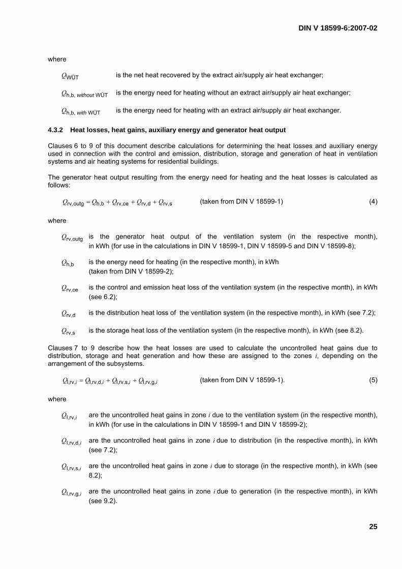
where
QWÜT is the net heat recovered by the extract air/supply air heat exchanger;
Qh,b, without WÜT is the energy need for heating without an extract air/supply air heat exchanger;
Qh,b, with WÜT is the energy need for heating with an extract air/supply air heat exchanger.
4.3.2 Heat losses, heat gains, auxiliary energy and generator heat output
Clauses 6 to 9 of this document describe calculations for determining the heat losses and auxiliary energy used in connection with the control and emission, distribution, storage and generation of heat in ventilation systems and air heating systems for residential buildings.
The generator heat output resulting from the energy need for heating and the heat losses is calculated as follows:
srv,drv,cerv,bh,outgrv, QQQQQ +++= (taken from DIN V 18599-1) (4)
where
Qrv,outg is the generator heat output of the ventilation system (in the respective month), in kWh (for use in the calculations in DIN V 18599-1, DIN V 18599-5 and DIN V 18599-8);
Qh,b is the energy need for heating (in the respective month), in kWh (taken from DIN V 18599-2);
Qrv,ce is the control and emission heat loss of the ventilation system (in the respective month), in kWh (see 6.2);
Qrv,d is the distribution heat loss of the ventilation system (in the respective month), in kWh (see 7.2);
Qrv,s is the storage heat loss of the ventilation system (in the respective month), in kWh (see 8.2).
Clauses 7 to 9 describe how the heat losses are used to calculate the uncontrolled heat gains due to distribution, storage and heat generation and how these are assigned to the zones i, depending on the arrangement of the subsystems.
iiii QQQQ g,rv,I,s,rv,I,d,rv,I,rv,I, ++= (taken from DIN V 18599-1). (5)
where
QI,rv,i are the uncontrolled heat gains in zone i due to the ventilation system (in the respective month), in kWh (for use in the calculations in DIN V 18599-1 and DIN V 18599-2);
QI,rv,d,i are the uncontrolled heat gains in zone i due to distribution (in the respective month), in kWh (see 7.2);
QI,rv,s,i are the uncontrolled heat gains in zone i due to storage (in the respective month), in kWh (see 8.2);
QI,rv,g,i are the uncontrolled heat gains in zone i due to generation (in the respective month), in kWh (see 9.2).

DIN V 18599-6:2007-02
26
This document does not include descriptions of cooling and air conditioning systems for residential buildings (see clause 1). The remaining cold gains of the residential ventilation system and air heating system due to external air and exhaust air ducts are negligible:
0c,rv,I, =iQ (taken from DIN V 18599-1) (6)
where
QI,rv,c,i are the uncontrolled cold gains in zone i due to the ventilation system (in the respective month), in kWh (for use in the calculations in DIN V 18599-1 and DIN V 18599-2).
The delivered energy Qrv,f for a heat generator integrated in the ventilation system is calculated in DIN V 18599-1:
regrv,grv,outgrv,frv, QQQQ −+= (taken from DIN V 18599-1) (7)
where
Qrv,f is the delivered energy for the heat generator (in the respective month), in kWh (calculated in DIN V 18599-1);
Qrv,outg is the generator heat output of the ventilation system (in the respective month), in kWh (calculated in DIN V 18599-1);
Qrv,g is the generation heat loss for the ventilation system (in the respective month), in kWh (see 9.2);
Qrv,reg is the heat input to the ventilation system due to heat recovered from extract air (in the respective month), in kWh.
The auxiliary energy is calculated as follows:
auxg,rv,auxs,rv,auxd,rv,auxce,rv,auxrv, QQQQQ +++= (taken from DIN V 18599-1). (8)
where
Qrv,aux is the auxiliary energy for the ventilation system (in the respective month), in kWh (calculated in DIN V 18599-1);
Qrv,ce,aux is the auxiliary energy for control and emission in the ventilation system (in the respective month), in kWh (see 6.3);
Qrv,d,aux is the auxiliary energy for distribution in the ventilation system (in the respective month), in kWh (see 7.3);
Qrv,s,aux is the auxiliary energy for storage in the ventilation system (in the respective month), in kWh (see 8.3);
Qrv,g,aux is the auxiliary energy for heat generation in the ventilation system (in the respective month), in kWh (see 9.3).
In general, the values are calculated for the zones defined in DIN V 18599-1. If there are different types of ventilation system or single ventilation system components within a particular zone (e.g. decentralized

DIN V 18599-6:2007-02
27
ventilation units for single rooms or reheating of supply air for single zones), then the calculations shall use an overall value which has been calculated from the individual parameters, weighted according to the proportion of the net floor space these rooms or zones take up (see equation (9)).
∑ ∑ ⎟⎟
⎠
⎞
⎜⎜
⎝
⎛⋅=
k k
kk A
AQQ (9)
4.3.3 Heat generation with combined heating
Combined heating is any heating method in which:
⎯ several heat generators contribute to the heat supply,
⎯ one or more heat generators satisfy different heating requirements (e.g. space heating (in the following also referred to as “heating” for short) and domestic hot water production), or
⎯ generators and heat recovery components are combined.
Due allowance shall be made for heat exchangers and heat pumps, where used in residential ventilation systems; additional reheating coils may have to be taken into account in the case of air heating systems.
Extract air/supply air heat exchangers
Calculation of the energy need of a zone for heating in accordance with DIN V 18599-2 takes into account extract air/supply air heat exchangers with and without ground/supply air heat exchangers (see A.2.2). This document describes how to calculate the temperature of the supply air leaving the heat exchanger as well as the mean ventilation system-driven air change rate (see clause 5); both of these parameters are used in the subsequent calculations in DIN V 18599-2.
The above provision applies to individual heat exchangers. The individual components in combinations of heat exchangers with other systems (e.g. an air heating system or extract air heat pump) are treated separately in the calculations. The heat exchanger in the combination is dealt with in the same way as an individual heat exchanger.
The energy need for heating calculated taking the heat exchanger into consideration is used for the calculations described in DIN V 18599-5 and/or this document.
The auxiliary energy for residential ventilation systems and air heating systems is calculated as specified in this document. In the case of air heating systems with water-filled reheating coils, the auxiliary energy for the water-filled part is calculated using the methods described in DIN V 18599-5, whereas the remaining auxiliary energy (e.g. for fans) is calculated as described in the present document.
Extract air heat pumps
Extract air heat pumps are devices for exploiting the heat content of the extract air of ventilation systems and air heating systems.
Where an extract air heat pump is used in combination with an extract air/supply air heat exchanger, the heat exchanger is accounted for as described above in this document and in DIN V 18599-2. When assessing the extract air heat pump, the reduced heat source temperature shall be taken into account as described in the present document.
Extract air/water heat pumps (source: extract air, sink: water) (see A.1.2 and A.2.4) transfer the heat which they generate to liquid heat carriers. These are assessed in clause 9 in the following sequence of steps:

DIN V 18599-6:2007-02
28
a) Determination of the required generator heat output Qw,outg for domestic hot water in accordance with DIN V 18599-8 (taking into consideration any values previously subtracted to account for any possible regenerative heat gains, e.g. from solar radiation).
b) Determination of the quantity of heat Qrv,outg which the extract air/water heat pump can supply as calculated in accordance with this document. If the extract air heat pump cannot supply the quantity of heat required in step a), the remainder to be supplied, Q*w,outg, is dealt with as described in DIN V 18599-8 (as in the case of systems without an extract air heat pump).
c) Determination of the required generator heat output for heating, Qh,outg, as described in DIN V 18599-5 (taking into consideration any values previously subtracted to account for any possible regenerative heat gains, e.g. from solar radiation).
d) Determination of the quantity of heat Qrv,w,outg which the extract air/water heat pump can supply for heating purposes (or, for systems with domestic hot water heating and space heating, in addition to the domestic hot water heating) as calculated in accordance with this document. If the extract air heat pump cannot supply the quantity of heat required in step c), the remainder to be supplied Q*h,outg is dealt with as described in DIN V 18599-5 (as in the case of systems without an extract air heat pump).
e) If the system being assessed is a system which exclusively uses electrical reheating for a water-filled back-up heater inside a unit, the generator heat output is assessed entirely as described in the present document, and the results are then used directly in the algorithms in DIN V 18599-1.
Steps a) and b) are not required for extract air/water heat pumps which are not used for domestic hot water production. The total quantity of heat supplied by the heat pump can be used for space heating purposes.
Extract air/supply air heat pumps (source: extract air, sink: supply air) (see A.2.3) transfer the generated heat exclusively to the supply air of the residential ventilation system. These are assessed in clause 9 in the following sequence of steps:
f) Determination of the required generator heat output for heating, Qh,outg, in accordance with this document.
g) Determination of the quantity of heat Qrv,h,outg which the extract air/supply air heat pump can supply as calculated in accordance with this document. In the case of water-filled systems, the remainder to be supplied, Q*h,b, will be an input value for the subsequent calculations described in DIN V 18599-5; in the case of air-filled systems (air heating), all calculations are carried out as described in the present document.
h) Domestic hot water heating is dealt with in DIN V 18599-8 (as in the case of systems without an extract air heat pump).
Extract air/supply air/water heat pumps (source: extract air, sink: supply air and water) (see A.2.5) transfer the recovered heat to the supply air and to the domestic hot water. These are assessed in clause 9 in the following sequence of steps:
i) Determination of the required generator heat output Qw,outg for domestic hot water in accordance with DIN V 18599-8 (taking into consideration any values previously subtracted to account for any possible regenerative heat gains, e.g. from solar radiation).
j) Determination of the quantity of heat Qrv,w,outg which the extract air/supply air/water heat pump can supply for heating domestic hot water as calculated in accordance with this document. If the extract air heat pump cannot supply the quantity of heat required in step a), the remainder to be supplied Q*w,outg is treated as described in DIN V 18599-8 (as in the case of systems without an extract air heat pump).
DIN V 18599-6:2007-02
29
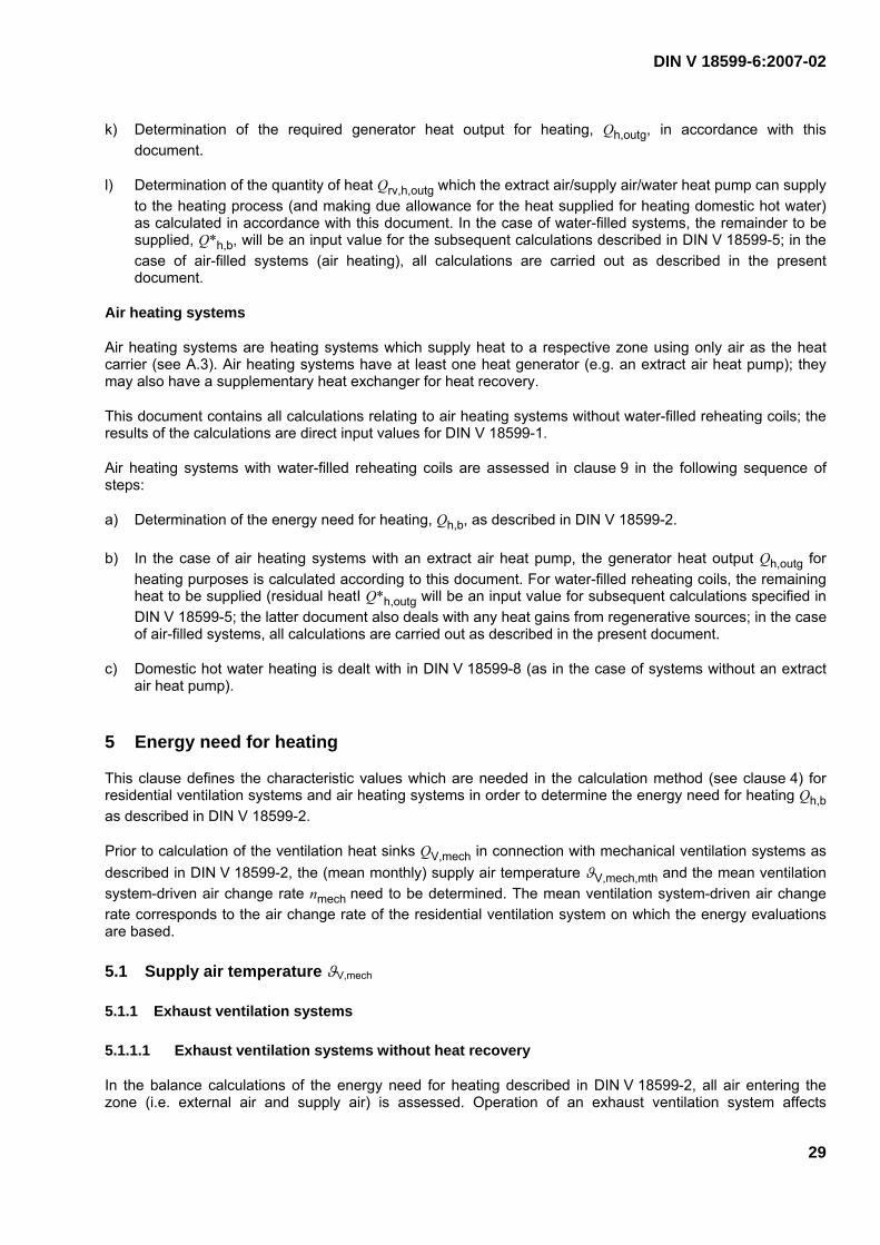
k) Determination of the required generator heat output for heating, Qh,outg, in accordance with this document.
l) Determination of the quantity of heat Qrv,h,outg which the extract air/supply air/water heat pump can supply to the heating process (and making due allowance for the heat supplied for heating domestic hot water) as calculated in accordance with this document. In the case of water-filled systems, the remainder to be supplied, Q*h,b, will be an input value for the subsequent calculations described in DIN V 18599-5; in the case of air-filled systems (air heating), all calculations are carried out as described in the present document.
Air heating systems
Air heating systems are heating systems which supply heat to a respective zone using only air as the heat carrier (see A.3). Air heating systems have at least one heat generator (e.g. an extract air heat pump); they may also have a supplementary heat exchanger for heat recovery.
This document contains all calculations relating to air heating systems without water-filled reheating coils; the results of the calculations are direct input values for DIN V 18599-1.
Air heating systems with water-filled reheating coils are assessed in clause 9 in the following sequence of steps:
a) Determination of the energy need for heating, Qh,b, as described in DIN V 18599-2.
b) In the case of air heating systems with an extract air heat pump, the generator heat output Qh,outg for heating purposes is calculated according to this document. For water-filled reheating coils, the remaining heat to be supplied (residual heatI Q*h,outg will be an input value for subsequent calculations specified in DIN V 18599-5; the latter document also deals with any heat gains from regenerative sources; in the case of air-filled systems, all calculations are carried out as described in the present document.
c) Domestic hot water heating is dealt with in DIN V 18599-8 (as in the case of systems without an extract air heat pump).
5 Energy need for heating
This clause defines the characteristic values which are needed in the calculation method (see clause 4) for residential ventilation systems and air heating systems in order to determine the energy need for heating Qh,b as described in DIN V 18599-2.
Prior to calculation of the ventilation heat sinks QV,mech in connection with mechanical ventilation systems as described in DIN V 18599-2, the (mean monthly) supply air temperature ϑV,mech,mth and the mean ventilation system-driven air change rate nmech need to be determined. The mean ventilation system-driven air change rate corresponds to the air change rate of the residential ventilation system on which the energy evaluations are based.
5.1 Supply air temperature ϑV,mech
5.1.1 Exhaust ventilation systems
5.1.1.1 Exhaust ventilation systems without heat recovery
In the balance calculations of the energy need for heating described in DIN V 18599-2, all air entering the zone (i.e. external air and supply air) is assessed. Operation of an exhaust ventilation system affects

DIN V 18599-6:2007-02
30
infiltration and window airing. It is not necessary to allow for the air that the ventilations system draws out of the building (exhaust air), hence the ventilation heat sinks related with mechanical ventilation systems do not have to be taken into account.
For exhaust ventilation systems without heat recovery, the supply air temperature ϑV,mech,mth is equal to the average external temperature ϑe,mth and is not to be determined due to the procedure outlined above.
5.1.1.2 Extract air/water heat pump
Extract air/water heat pumps are treated as heat generators in the balance calculations (see clause 9). By analogy with 5.1.1.1 it is not necessary to calculate the supply air temperature ϑV,mech,mth.
5.1.2 Supply and exhaust ventilation systems
5.1.2.1 Supply and exhaust ventilation systems without heat recovery
The supply air temperature is equal to the average external temperature, ϑe,mth.
ϑV,mech,mth = ϑe,mth (taken from DIN V 18599-2) (10)
where
ϑV,mech,mth is the mean supply air temperature (in the respective month), in °C;
ϑe,mth is the average external temperature (in the respective month), in °C (taken from DIN V 18599-10).
5.1.2.2 Extract air/supply air heat exchangers
Where extract air/supply air heat exchangers are used, the supply air temperature is calculated on the basis of the overall efficiency of the heat recovery system in the respective month, ηWÜT,mth, (see equation (11)).
If the residential ventilation system is not operated all the year in conjunction with heat recovery, then the mean supply air temperature is assumed to be equal to the average external temperature for the times during which the heat recovery system is not in operation. This may be the case for residential ventilation systems which have a summer bypass or a summer manifold.
ϑV,mech,mth = ϑe,mth + ηWÜT,mth · (ϑex – ϑe,mth) (taken from DIN V 18599-2) (11)
where
ϑV,mech,mth is the mean supply air temperature (in the respective month), in °C;
ϑe,mth is the average external temperature (in the respective month) in °C (taken from DIN V 18599-10);
ϑex is the mean extract air temperature in °C;
ηWÜT,mth is the overall efficiency of heat recovery by the heat exchanger.
The heat supply efficiency η′WRG shall be used in equation (12) for calculating the overall efficiency ηWÜT,mth of the heat recovery system. The heat supply efficiency describes the achieved supply air temperature increase in relation to the maximum possible temperature rise. The heat supply efficiency can be expressed

DIN V 18599-6:2007-02
31
as a mean value for the heating season. Besides the operating characteristics of the heat exchanger (WÜT), the heat dissipated by electrical components (e.g. fans, controls) also affects the heat supply efficiency.
If, as an alternative to the heat supply efficiency, characteristics in European Standards (e.g. the temperature ratio ηt from DIN EN 308, DIN EN 13141-7 or DIN EN 13141-8) are to be used for calculating the overall efficiency of the heat recovery system, then these shall be converted accordingly, taking into account any deviating test conditions.
In the supply air temperature calculations, the behaviour of the ventilation unit in defrost mode shall be taken into account. The following cases can generally be distinguished:
a) switching off or reducing the speed of the supply air fan,
b) pre-heating the external air with a ground/supply air heat exchanger, and
c) preheating the external air with a heating coil (heated by electricity or water).
Equation (12) contains a reduction factor that accounts for defrosting of the ventilation unit when this is effected by switching off the supply air fan, as a function of the external temperature.
If the ventilation system is equipped with a ground/supply air heat exchanger for preheating the air which, in keeping with accepted engineering practice, can ensure a frost-free supply of air, a supplementary factor is added to the overall efficiency of heat recovery ηWÜT,mth as expressed by equation (12). This supplementary factor takes into account the fact that freedom from frost of the ventilation unit as well as an increase in heat recovery is ensured.
If the external air is preheated with a heating coil, no correction factor is required when calculating the overall efficiency of heat recovery as expressed by equation (12). The energy used to preheat the air with a heating coil is accounted for in the calculations explained in clause 9.
The heat losses through the surface of the equipment shall be taken into account using equation (12) as a function of the thermal insulation of the equipment housing and the location where the ventilation unit is installed.
The airtightness of the ventilation unit and the resulting leakage losses shall also be taken into account when applying equation (12).
The supply air and extract air volume flows shall be controlled by suitable components so as to ensure a sustained balanced volume flow. The extract air volume flow rate is allowed to differ from the supply air volume flow rate by ± 10 %.
The correction factors for the heat supply efficiency in equation (12) only need to be applied if:
⎯ they were not taken into consideration when the ventilation unit was tested, or
⎯ the conditions of installation deviate from the test conditions.
ηWÜT,mth = WRGη′ · (1 – fv,WÜT,Frost – fv,WÜT,Wärme – fv,WÜT,Dicht) (12)
where
WRGη′ is the heat supply efficiency in accordance with the Energieeingsparverordnung, expressed as the mean value for the heating season (without taking into account frost operation, heat losses and airtightness of the unit);
fv,WÜT,Frost is a factor taking into account defrost mode;

DIN V 18599-6:2007-02
32
fv,WÜT,Wärme is a factor taking into account the heat losses of the ventilation unit,
fv,WÜT,Dicht is a factor taking into account the airtightness of the ventilation unit.
Table 4 — General boundary conditions for determining the overall efficiency ηWÜT,mth
Parameters Symbol Unit Value
Defrost mode
≥ –6 °C 0,06
< –6 °C 0,04
< –9 °C 0,02 Supply air fan is switched off when external temperature is
< –12 °C 0
Air preheating by ground/supply air heat exchanger –0,04
Air preheating by heating coil
fv,WÜT,Frost –
0
Heat losses in the ventilation unit
Installation in a heated area 0
Installation in an unheated area with Rλa ≥ 0,5 m2K/W 0
Installation in an unheated area with Rλa < 0,5 m2K/W
fv,WÜT,Wärme –
0,02
Airtightness of the ventilation unit
Leakage < 2,5 % · mmech,V& b at a positive/negative pressure of 100 Pa
0
Leakage < 5 % · mmech,V& b at a positive/negative pressure of 100 Pa
fv,WÜT,Dicht –
0,01
a Thermal resistance of the ventilation unit housing. b Mean value of the volume flow rate range of the ventilation unit.
The methods described in 5.1.2.3 and 5.1.2.4 are used to calculate the supply air temperature if extract air/supply air heat exchangers are used in combination with extract air heat pumps.
Default values
ϑex = 21 °C
Extract air/supply air heat exchangers:
⎯ with entire system, constructed after 1999;
⎯ without ground/supply air heat exchanger;
⎯ with supply air fan switched off when ϑe ≥ –6°C;
⎯ installed in an unheated area;
⎯ leakage mmech,%5 V&⋅<

DIN V 18599-6:2007-02
33
Default value: ηWÜT,mth = 0,60
Improved default value: ηWÜT,mth = 0,80.
If the improved default value ηWÜT,mth = 0,80 is used in the calculations, the product data of the extract air/supply air heat exchanger shall be at least equal to the improved default value.
For residential ventilation systems constructed before 1999, the overall heat recovery efficiency shall be reduced by 10 % (default: 0,54/improved default: 0,72).
For residential ventilation systems which are additionally equipped with a ground/supply air heat exchanger, the overall heat recovery efficiency shall be increased by 10 % (default: 0,66/improved default: 0,88).
Table 5 — Default values for monthly supply air temperature for systems with extract air/supply air heat exchangers without upstream ground/supply air heat exchangers, constructed after 1999
Month Jan Feb Mar Apr May June July Aug Sep Oct Nov Dec
ϑe,mth –1,3 °C 0,6 °C 4,1 °C 9,5 °C 12,9 °C 15,7 °C 18,0 °C 18,3 °C 14,4 °C 9,1 °C 4,7 °C 1,3 °C
ϑV,mech for ηWÜT,mth = 0,60 12,1 °C 12,8 °C 14,2 °C 16,4 °C 17,8 °C 18,9 °C 19,8 °C 19,9 °C 18,4 °C 16,2 °C 14,5 °C 13,1 °C
ϑV,mech for ηWÜT,mth = 0,80 16,5 °C 16,9 °C 17,6 °C 18,7 °C 19,4 °C 19,9 °C 20,4 °C 20,5 °C 19,7 °C 18,6 °C 17,7 °C 17,1 °C
NOTE If the ventilation system is not operated all year round or is operated without heat recovery in the summer months, then ϑV,mech equals ϑe,mth for the periods when the system is off or is operated without heat recovery.
5.1.2.3 Extract air/supply air heat pumps
According to the calculation method (see clause 4), extract air/supply air heat pumps are treated as heat generators in the balances (see clause 9). The heat pump is not taken into account when calculating the supply air temperature ϑV,mech,mth for the calculations of the energy need for heating described in DIN V 18599-2.
If no extract air/supply air heat exchanger is installed upstream, equation (10) is used to calculate the supply air temperature.
If the extract air/supply air heat pump is combined with an upstream extract air/supply air heat exchanger, the calculation method (see clause 4) does not take the heat pump into consideration when calculating the supply air temperature ϑV,mech,mth for the calculations of the energy need for heating described in DIN V 18599-2. If an extract air/supply air heat exchanger is installed upstream, equation (11) is used to calculate the supply air temperature ϑV,mech,mth.
5.1.2.4 Extract air/water heat pumps
According to the calculation method (see clause 4), extract air/water heat pumps are treated as heat generators in the balances (see clause 9). The heat pump is not taken into account when calculating the supply air temperature ϑV,mech,mth for the calculations of the energy need for heating described in DIN V 18599-2.

DIN V 18599-6:2007-02
34
If no extract air/supply air heat exchanger is installed upstream, equation (10) is used to calculate the supply air temperature.
If an extract air/supply air heat exchanger is installed upstream, the procedure is the same as that for extract air/supply air heat pumps (see 5.1.2.3).
5.1.2.5 Extract air/supply air/water heat pumps
According to the calculation method (see clause 4), extract air/supply air/water heat pumps are treated as heat generators in the balances (see clause 9). The heat pump is not taken into account when calculating the supply air temperature ϑV,mech,mth for the calculations of the energy need for heating described in DIN V 18599-2.
If no extract air/supply air heat exchanger is installed upstream, equation (10) is used to calculate the supply air temperature.
If an extract air/supply air heat exchanger is installed upstream, the procedure is the same as that for extract air/supply air heat pumps (see 5.1.2.3).
Default values
Where systems comprise an extract air/supply air heat exchanger combined with an extract air heat pump, a supply air temperature ϑV,mech,mth for a value of ηWÜT,mth equal to 0,60 (see Table 5) can be used as a default value for the extract air/supply air heat exchanger.
5.1.3 Air heating systems
According to the calculation method (see clause 4), air heating systems are treated as heat generators in the balances (calculation of the generator heat output being described in clause 9). The air heating (or heating function) is not taken into account when calculating the supply air temperature ϑV,mech,mth for the calculations of the energy need for heating described in DIN V 18599-2. This rule applies irrespective of the air heating method and irrespective of whether monovalent air heating systems (i.e. systems in which only air is used) or bivalent heating systems (with water-filled reheating coils) are employed.
Depending on whether a heat exchanger is installed or not, the supply air temperature ϑV,mech,mth is calculated in accordance with 5.1.2.
5.2 Mean ventilation system-driven air change rate nmech
5.2.1 Exhaust ventilation systems
In the balance calculations of the energy need for heating described in DIN V 18599-2, all air entering the zone (i.e. both external air and supply air) is assessed. Operation of an exhaust ventilation system affects infiltration and window airing. It is not necessary to allow for the air flowing out through the ventilation system (extract air).
In DIN V 18599-2, the value of the mean ventilation system-driven air change rate nmech for exhaust ventilation systems is set at zero, as only the air entering the zone is assessed, but not the air leaving the zone. Operation of an exhaust ventilation system, however, affects the replacement air entering from the outside and is taken into consideration accordingly when calculating the air change rate through windows nwin in DIN V 18599-2.
If an extract air/water heat pump is used in the exhaust ventilation system, the heat pump is treated as a heat generator in clause 9. In that clause, the mean ventilation system-driven extract air change rate nmech,ABL is

DIN V 18599-6:2007-02
35
determined for calculation of the generator heat output, the heat losses and the auxiliary energy used for heat generation.
5.2.2 Supply and exhaust ventilation systems
The mean daily ventilation system-driven air change rate nmech of supply and exhaust ventilation systems with a constant air volume flow is calculated by applying equation (13), similarly to the method described in DIN V 18599-2.
h24mechV,
ZULmech,mecht
nn ⋅= (taken from DIN V 18599-2) (13)
where
nmech is the mean daily ventilation system-driven air change rate, in h–1;
nmech,ZUL is the supply air change rate while the ventilation system is in operation, in h–1;
tV,mech is the daily operating time of the ventilation system, in h/d.
Supplementary effects such as:
⎯ season-related shut-down,
⎯ intermittent operating mode (special night-time and weekend operating modes),
⎯ several different system volume flow stages which can be selected as required (e.g. minimum, basic and demand-controlled ventilation in accordance with DIN 1946-6) and
⎯ user-independent, demand-dependent system volume flow control on the basis of a suitable reference variable, subject to proof of acceptable air quality conditions in terms of hygiene and building physics in accordance with generally accepted rules of technology
can all be accounted for by equation (14). The mean ventilation-driven air change rate nmech,mth obtained by means of equation (14) shall be used in the calculations in DIN V 18599-2.
( )
daymech,rv,mthmech,rv,
,mech,rv,mth,mech,rv,,ZULmech,
mthmech, tt
ttn
n iidayii
⋅
⋅⋅
=∑
(14)
where
nmech,mth is the mean ventilation system-driven air change rate (in the respective month), in h–1;
nmech,ZUL,i is the supply air change rate at fan stage i, in h–1;
trv,mech,mth,i is the operating time of the fan at stage i (in the respective month), in d;
trv,mech,day,i is the daily operating time of the fan at stage i, in h;

DIN V 18599-6:2007-02
36
trv,mech,mth is the total operating time of the ventilation system (in the respective month) (see Table 6), in d;
trv,mech,day is the total daily operating time of the ventilation system (see Table 6), in h;
Table 6 — General boundary conditions for determining the operating time trv,mech
Parameters Symbol Unit Value
Operating time per month: heating season operating mode year-round operating mode
trv,mech,mthd per month
heating seasona Jan. to Dec.
Operating time per day trv,mech,day h/d 8 to 24
a Operation during the heating season: on all days of the months for which the following applies (according to DIN V 18599-2): energy need for heating Qh,mth > 0 (heating months without operation of ventilation system)
As an alternative, the heating-time method described below can be applied.
b Year-round operation: on all days from January to December (in conjunction with a summer shut-down of the heat exchanger, e.g. by using a bypass or a summer manifold).
As an alternative to considering the heating months in the heating season, the total operating time per month trv,mech,mth of the ventilation system can be calculated on the basis of the heating times th per heating month (see equation (15) and DIN V 18599-2). In this case, the heating time th shall be calculated without taking the ventilation system into account.
h/d24h
mthmech,rv,t
t = (15)
where
th is the heating time (in the respective month), in h (taken from DIN V 18599-2:2005-07, Annex D).
Default values
nmech = 0,4 h–1 (mean ventilation system-driven air change rate according to DIN V 18599-10);
trv,mech,mth = heating season (heating-months calculation method);
trv,mech,day = 24 h/d.
5.2.3 Air heating systems
In the balance equations, air heating systems are treated as heat generators (see clause 9). Air heating (or the heating function) is not taken into account in the calculations of the mean ventilation-driven air change rate nmech for the calculations of the energy need for heating described in DIN V 18599-2. This rule applies irrespective of the method by which the air is heated, even when the ventilation system-driven air change rates nh,mech are variable in relation to the load when the heating is in operation.
As in the procedure used to calculate the supply air temperature (see 5.1.2 and 5.1.3), only the ventilation function is taken into consideration here for determining the energy need for heating.

DIN V 18599-6:2007-02
37
Default values
nmech = 0,4 h–1 (mean ventilation system-driven air change rate according to DIN V 18599-10);
trv,mech,mth = heating season (based on heating months);
trv,mech,day = 24 h/d.
6 Control and emission
6.1 General
This clause specifies the parameters required in the calculation method (see clause 4) for determining the energy expenditure for heat control and emission in residential ventilation systems and air heating systems.
The control and emission heat losses, Qrv,ce, are taken into account when determining the generator heat output Qrv,outg as described in DIN V 18599-1.
The auxiliary energy for control and emission, Qrv,ce,aux, is taken into account when determining the delivered auxiliary energy Qf,aux described in DIN V 18599-1.
6.2 Heat losses Qrv,ce
The control and emission heat losses Qrv,ce are calculated on a monthly basis, using equation (16).
mthb,h,cerv,
hydrintradmthce,rv, 1 Q
fffQ ⋅⎟
⎟⎠
⎞⎜⎜⎝
⎛−
⋅⋅=
η (16)
where
Qrv,ce,mth are the monthly control and emission heat losses (in the respective month), in kWh;
Qh,b,mth is the monthly energy need for heating (in the respective month), in kWh (taken from DIN V 18599-2);
frad is a factor taking into account the effect of radiation (only of relevance when considering large indoor spaces over 4 m in height);
fint is the factor for intermittent operation (intermittent: option of reducing the temperature in single rooms as a function of time);
fhydr is the hydraulic balance factor;
ηrv,ce is the overall efficiency for heat control and emission in the space.
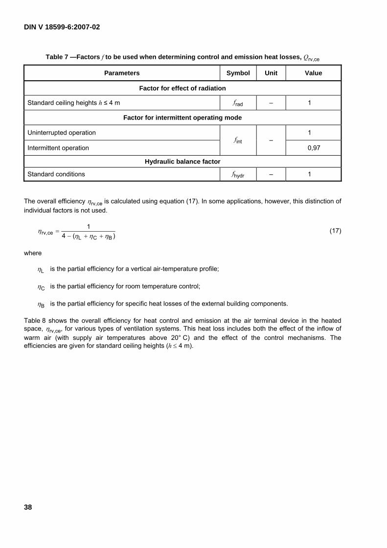
DIN V 18599-6:2007-02
38
Table 7 —Factors f to be used when determining control and emission heat losses, Qrv,ce
Parameters Symbol Unit Value
Factor for effect of radiation
Standard ceiling heights h ≤ 4 m frad – 1
Factor for intermittent operating mode
Uninterrupted operation 1
Intermittent operation fint –
0,97
Hydraulic balance factor
Standard conditions fhydr – 1
The overall efficiency ηrv,ce is calculated using equation (17). In some applications, however, this distinction of individual factors is not used.
)(41
BCLcerv, ηηη
η++−
= (17)
where
ηL is the partial efficiency for a vertical air-temperature profile;
ηC is the partial efficiency for room temperature control;
ηB is the partial efficiency for specific heat losses of the external building components.
Table 8 shows the overall efficiency for heat control and emission at the air terminal device in the heated space, ηrv,ce, for various types of ventilation systems. This heat loss includes both the effect of the inflow of warm air (with supply air temperatures above 20° C) and the effect of the control mechanisms. The efficiencies are given for standard ceiling heights (h ≤ 4 m).

DIN V 18599-6:2007-02
39
Table 8 — Overall efficiencyηrv,ce for heat control and emission in the room
System Temperature control method ηrv,ce
Single-room control with PI controller (with optimization function) 0,93
Single-room control with P controller (1 K) 0,92
Zone control with P controller (1 K) – with heat exchanger 0,91
Zone control with P controller (1 K) – without heat exchanger 0,90
Extract air/supply air heat pump with heat exchanger and without single-room control (with central master control and pilot room control) including
back-up heating with single-room control by P controller (1 K) 0,93
Extract air/supply air heat pump without heat exchanger and without single-room control (with central master control and pilot room control) including
back-up heating with single-room control by P controller (1 K) 0,91
Extract air/supply air heat pump without single-room control (with central master control and pilot room control) only for the heat pump component 0,90
Residential ventilation systems with air temperaturesa ϑL,m > ϑi
Air terminal device at external wall
Extract air/supply air heat pump without single-room control (without central master control) only for the heat pump component 0,88
Single-room control with PI controller (with optimization function) 0,90
Single-room control with P controller (1 K) 0,89
Zone control with P controller (1 K) – with heat exchanger 0,88
Zone control with P controller (1 K) – without heat exchanger 0,87
Extract air/supply air heat pump with heat exchanger and without single-room control (with central master control and pilot room control) including
back-up heating with single-room control by P controller (1 K) 0,90
Extract air/supply air heat pump without heat exchanger and without single-room control (with central master control and pilot room control) including
back-up heating with single-room control by P controller (1 K) 0,88
Extract air/supply air heat pump without single-room control (with central master control and pilot room control) for the heat pump component only
0,87
Residential ventilation systems with air temperaturesa ϑL,m > ϑi
Air terminal device at internal wall
Extract air/supply air heat pump without single-room control (without central master control) for the heat pump only 0,85
Heat exchanger without supplementary reheating 1,00
Heat exchanger with supplementary reheating 0,99
Residential ventilation systems with air temperaturesa ϑL,m ≤ ϑi Externally mounted air transfer device 1,00
a Mean air temperature of supply air from air distribution ductwork taken from Table 10.
Equation (18) is used to calculate the annual control and emission heat losses.

DIN V 18599-6:2007-02
40
∑= mthce,rv,ace,rv, QQ (18)
where
Qrv,ce,a are the annual control and emission heat losses, in kWh/a;
Qrv,ce,mth are the control and emission heat losses (in the respective month) as calculated by equation (16), in kWh.
Exhaust ventilation systems and supply and exhaust ventilation systems without reheating (without heat recovery or with extract air/supply air heat exchangers only) have no control and emission heat losses (i.e. Qrv,ce = 0).
Default values
frad = 1
fint = 1
fhydr = 1
6.3 Auxiliary energy Qrv,ce,aux
Equation (19) is used to calculate the auxiliary energy required for improving the heat transfer processes associated with residential ventilation and air heating systems and which is not dealt with in clauses 7 and 9.
( )∑ ⋅⋅=i
i ttPQ daymech,rv,mthmech,rv,c,mthaux,ce,rv, (19)
where
Qrv,ce,aux,mth is the auxiliary energy for control and emission (in the respective month), in kWh;
Pc,i is the rated power of controller i dependent on the system design, in W;
trv,mech,mth is the total operating time of the ventilation system (in the respective month) (see Table 6), in d;
trv,mech,day is the total daily operating time of the ventilation system (see Table 6), in h;
Table 9 shows default values for the rated power Pc of the controller as a function of the controller type.
Table 9 — Rated power Pc of the controller for heat control and emission in the room
Type of controller Symbol Unit Value
P controller (1 K) 0,1
PI controller with optimization function 0,1
PID controller 0,1
Two-step bimetallic strip controller
Pc W
0,1

DIN V 18599-6:2007-02
41
The annual auxiliary energy for heat control and emission is calculated by adding together the values for the whole year (see equation (20)).
∑= mthaux,ce,rv,aaux,ce,rv, QQ (20)
where
Qrv,ce,aux,a is the annual auxiliary energy for heat control and emission, in kWh;
Qrv,ce,aux,mth is the auxiliary energy for heat control and emission (in the respective month) as calculated by equation (19), in kWh.
Exhaust ventilation systems without demand control and supply and exhaust ventilation systems without controls for single rooms or zones do not require auxiliary energy for control and emission (i.e. Qrv,ce,aux = 0).
7 Distribution
7.1 General
This clause specifies the parameters needed in the calculation method (see clause 4) for determining the energy expenditure for heat distribution in residential ventilation systems and air heating systems.
The heat losses Qrv,d occurring during distribution are taken into account when calculating the generator heat output Qrv,outg described in DIN V 18599-1.
The auxiliary energy for distribution Qrv,d,aux is taken into account when calculating the delivered auxiliary energy Qf,aux as described in DIN V 18599-1.
7.2 Heat losses Qrv,d and uncontrolled heat gains Ql,rv,d
Heat losses in the air ductwork occur when warm supply air is distributed and extract air is vented. In this clause, the heat losses which occur
⎯ in the supply air ducts between the heat generator and the air terminal devices and
⎯ in the extract air ducts located outside the thermal envelope
are identified. The general heat loss in a section j of an air duct is determined per month using equation (21).
( ) daymech,rv,mthmech,rv,amthm,u,mthm,L,mth,d,rv, ttfLUQ jjj ⋅⋅⋅−⋅⋅= ϑϑ (21)
where
Qrv,d,mth,j is the heat loss of section j of the ductwork (in the respective month), in kWh;
Ui is the linear thermal transmittance (design value or from Table 11), in W/(m · K);
Lj is the length of the respective duct section j (design value or from Table 11), in m;
ϑL,m,mth is the mean monthly air temperature in the ducts (see Table 10 or equation (24)), in °C;

DIN V 18599-6:2007-02
42
ϑu,m,mth is the average monthly ambient temperature (see Table 10), in °C;
fa is the heat loss factor, dependent on the arrangement of the components (see Table 10);
trv,mech,mth is the total operating time of the ventilation system (in the respective month) (see Table 6), in d;
trv,mech,day is the total daily operating time of the ventilation system (see Table 6), in h.
Equation (21) applies both to ductwork in residential ventilation systems (supply air operation without recir-culation and without an additional heating function) as well as to air heating systems (with and without recirculation air operation). If supply air ducts are installed within the thermal envelope and the air temperature in these ducts is always lower than or equal to the room temperature, the heat losses from these ducts can be ignored (i.e. Qrv,d,mth,j = 0). The same applies to main ducts between the ventilation unit and the place where the ducts enter the thermal envelope if these ducts are shorter than 2 m and have thermal insulation at least 50 mm in thickness (i.e. Qrv,d,mth,j = 0). Apart from this, all ventilation ducts in which a temperature gradient exists shall be taken into account; an exception to this is the exhaust air duct downstream of the heat exchanger and outside the thermal envelope.
The monthly and annual heat losses of an entire ventilation air distribution ductwork comprising several different duct sections (e.g. ducts inside and outside the thermal envelope and with different heat insulation) are calculated by adding together the values of the individual duct sections j for the respective periods (see equations (22) and (23)). The absolute value of the heat losses shall always be applied in these equations, since the heat gain of an exhaust air duct located inside the thermal envelope shall also be considered a loss.
∑=j
jQQ mth,d,rv,mthd,rv, (22)
where
Qrv,d,mth is the monthly heat loss of the duct system, in kWh;
Qrv,d,mth,j is the heat loss of section j of the duct system (in the respective month) (see equation (21)), in kWh.
∑= mthd,rv,ad,rv, QQ (23)
where
Qrv,d,a is the annual heat loss of the duct system, in kWh.
The heat losses of ventilation air distribution ductwork can be calculated if the lengths, the locations and the linear thermal transmittances of the individual duct sections are known. These values can be obtained from detailed designs, it being necessary to take the boundary conditions specified in Tables 6, 10 and 11 into account. Any heat losses occurring in ventilation systems without heat recovery (exhaust ventilation systems or supply and exhaust ventilation systems) shall be neglected.
If a residential ventilation system is equipped with an extract air/supply air heat exchanger (without a reheating coil and extract air/supply air heat pump), equation (24) shall be used to determine the mean temperature of the supply air ducts. If an extract air/supply air heat pump or a supplementary reheating coil (e.g. an electric reheating coil) is installed, then the mean circuit air temperatures given in Table 10 shall be used.
ϑ L,m,mth = ϑv,mech,mth (calculated using equation (11)) (24)

DIN V 18599-6:2007-02
43
where
ϑ L,m,mth is the mean air temperature in the duct (in the respective month), in °C;
ϑv,mech,mth is the mean supply air temperature (in the respective month), in °C.
Exhaust systems and single-room ventilation systems have no distribution heat losses (i.e. Qrv,d = 0).
If no detailed ductwork design plans for the supply and exhaust ventilation systems and air heating systems are available, the heat losses of a section of a ventilation duct can be estimated on the basis of the boundary conditions listed in Tables 10 and 11. The data given there apply to zones (flats or houses) with a net volume of up to 1 250 m3 or a net floor area of up to 500 m2. For all ventilation systems in which any one ventilation ductwork is used to serve a zone of more than 1 250 m3, detailed calculations shall always be carried out using equations (21) and (23).
It is assumed that an average supply air ductwork (the warm section downstream of the heat generator) comprises three different zones: V, S and A. Zone V is for horizontal air distribution from the heat generator to the vertical ducts (or to the spaces to be supplied), zone S is for vertical air distribution, and zone A includes the connecting ducts to the air supply terminal devices in the heated parts of the dwelling. The exhaust air series of ducts also comprises connecting ducts and distribution ducts, but only the distribution ducts in the unheated zones are thermally relevant.
If the distribution ducts are installed inside the thermal envelope, it can be assumed that the length of the main ducts between the heat generator and the location where they enter the thermal envelope is shorter than 2 m and can therefore be neglected.
The heat losses Qrv,d,mth,j of duct sections j are assigned to the zones i in which the ducts are located. They correspond to an uncontrolled heat gain in the individual zones i.
( )ij
ji QQ ∑= mth,d,rv,mth,d,rv,I, (25)
where
QI,rv,d,mth,i is an uncontrolled heat gain of zone i due to the ventilation system (in the respective month), in kWh, (for use in the calculations in DIN V 18599-1 and DIN V 18599-2);
Qrv,d,mth,j is the heat loss of section j of the ductwork in zone i (in the respective month) (see equation (21)), in kWh.

DIN V 18599-6:2007-02
44
Default values
Table 10 — Boundary conditions 1 for default values used to determine heat losses Qrv,d
Parameter Symbol Unit Value
Arrangement-related heat loss factor
Components outside the thermal envelope 1
Components inside the thermal envelope fa –
0,15
Mean air temperature in ventilation air distribution ductwork: supply aira
Extract-air/supply air heat exchanger, not reheated (v,mech,mth (from Table 5)
Extract air/supply air heat pump (not reheated) or air heating system (with load-dependent control) for a design supply air temperature of 35 °C
29b
Extract air/supply air heat exchanger and extract air/supply air heat pump (not reheated) or air heating system (with load-dependent control) for a design supply air temperature of 45 °C
35b
Air heating system (with load-dependent control) for a design supply air temperature of 55 °C
(L,m,mth °C
41b
Mean air temperature in ventilation air distribution ductwork: extract air/exhaust air
Extract air ducts 21
Exhaust air ducts inside the thermal envelope ϑL,m,mth °C
ϑex – (WÜT,mth · ((ex – (e,mth)
Mean ambient temperature
Inside the thermal envelope 21
Outside the thermal envelope (U,m,mth °C f((e,mth) (calculated in
DIN V 18599-2)
a The mean air temperature of the supply air distribution ductwork takes into account average load on this ductwork. b As a simplification, the mean annual supply air temperature can be used in the calculations.

DIN V 18599-6:2007-02
45
Table 11 — Boundary conditions 2 for default values used to determine heat losses Qrv,d
Parameter Symbol Unit Section V/Section Sd Section Ad
Installation location Outside the thermal
envelope
Inside the thermal
envelope
Inside the thermal envelope
Thermal transmittance: up to 1995 0,65a 0,85b 0,85b
Thermal transmittance: after 1995
U W/(m · K)
0,45c 0,85b 0,85b
Length of supply air ducts LV = 10 + 0,01 · V
LS = 2 + hG · (nG – 1) LA =0,04 · V
Length of extract air ducts
L m LV = 7,5 + 0,01 · V
LS = 2 + hG · (nG – 1)no thermal relevance
a This U value is based on a duct diameter of roughly 125 mm and approximately 30 mm insulation thickness. b This U value is based on a duct diameter of roughly 125 mm and approximately 20 mm insulation thickness. c This U value is based on a duct diameter of roughly 125 mm and approximately 50 mm insulation thickness. d where
V is the net volume of the building nG is the number of heated storeys hG is the storey height in m.
7.3 Auxiliary energy Qrv,d,aux
The auxiliary energy required by the fans for distributing the air through the ventilation ductwork can be calculated either separately (Qrv,d,aux) or in conjunction with the auxiliary energy Qrv,g,aux for the residential ventilation unit if the fan is an integral component of the ventilation unit and is included in the energy requirement considerations for this unit (see 9.3).
If separate fans are used (e.g. for recirculation air operation), they shall be taken into account by applying equation (26).
( )∑ ⋅⋅=i
i ttPQ daymech,rv,mthmech,rv,Vent,mthaux,d,rv, (26)
where
Qrv,d,aux,mth is the auxiliary energy for distribution (in the respective month), in kWh;
PVent,i is the rated capacity of the fan i, including fan controls according to design, in W;
trv,mech,mth is the total operating time of the ventilation system (in the respective month) (see Table 6), in d;
trv,mech,day is the total daily operating time of the ventilation system (see Table 6), in h.
The annual auxiliary energy for distribution is calculated by adding together the values for the whole year (see equation (27)).

DIN V 18599-6:2007-02
46
∑= mthaux,d,rv,aaux,d,rv, QQ (27)
where
Qrv,d,aux,a is the annual auxiliary energy for distribution, in kWh;
Qrv,d,aux,mth is the auxiliary energy for distribution (in the respective month) calculated using equation (26), in kWh.
Default values
The default values shown in Table 16 can be used for fans operated separately.
8 Storage
8.1 General
This clause specifes the parameters needed in the calculation method (see clause 4) for determining the energy expenditure for heat storage in residential ventilation systems and air heating systems.
The heat losses Qrv,s occurring during storage are taken into account when determining the generator heat output Qrv,outg as described in DIN V 18599-1.
The auxiliary energy Qrv,s,aux for storage is taken into account when determining the delivered auxiliary energy Qf,aux as described in DIN V 18599-1.
8.2 Heat losses Qrv,s and uncontrolled heat gains QI,rv,s
If a heat storage tank in a residential ventilation unit is used in conjunction with an extract air/water heat pump, the storage heat loss is calculated using equation (28).
VerbindungsB,mth,hmthm,u,srv,
mths,rv, K45)(
fQtQ ⋅⋅⋅−
=ϑϑ
(28)
where
Qrv,s,mth is the storage heat loss (in the respective month), in kWh;
ϑrv,s is the mean temperature of the storage tank, in °C;
ϑu,m,mth is the mean monthly ambient temperature (see Table 10), in °C;
th,mth is the number of heating days per month, in d (taken from Table 6);
QB,s is the stand-by heat loss (per day), in kWh;
fVerbindung is the connection heat-loss factor.

DIN V 18599-6:2007-02
47
The stand-by heat loss QB,s of the storage tank shall be measured in accordance with DIN 4753-8 (at a mean temperature gradient of 45 K between the storage water and the space in which the storage tank is installed). The monthly heat loss of the storage tank Qrv,s,mth can then be calculated from the stand-by heat losses thus measured, the installation location and the mean heating circuit temperature.
If the stand-by heat loss QB,s of the storage tank is not known (i.e. no measurements as described in DIN 4753-8 are available), this can be obtained in a simplified manner by applying equation (29) (conforming with minimum requirements according to DIN 4735-8).
QB,s = 0,4 + 0,14 · V0,45 (29)
where
QB,s is the stand-by heat loss (per day), in kWh;
V is the nominal capacity of the storage tank, in litres.
If the storage tank and the heat generator (extract air/water heat pump) are installed in one and the same unit, the heat loss factor of the connection can be set at unity (i.e. fVerbindung = 1). If the storage tank is installed separately in a room, then a general factor fVerbindung = 1,2 is applied for the heat losses of the storage piping system. In the case of other arrangements and layouts, the heat losses of the connections shall be calculated in accordance with DIN V 18599-5.
The annual storage heat loss is calculated by adding together the values for the whole year (see equation (30)).
∑= mths,rv,as,rv, QQ (30)
where
Qrv,s,a is the storage heat loss (in the respective year), in kWh;
Qrv,s,mth is the storage heat loss (in the respective month) as calculated by equation (28), in kWh.
The heat losses Qrv,s,mth of the storage tank are assigned to the zone in which the storage tank is installed. It corresponds to an uncontrolled heat gain due to storage, Ql,rv,s,mth.
mths,rv,mths,rv,l, QQ = (31)
where
Ql,rv,s,mth is an uncontrolled heat gain due to storage (in the respective month), in kWh (for use in the calculations in DIN V 18599-1 and DIN V 18599-2);
Qrv,s,mth is the storage heat loss (in the respective month) as calculated by equation (28), in kWh.
Default values
Extract air/water heat pump and storage tank are both in the same unit:
fVerbindung = 1
V = 120 l
QB,s = 1,6 kWh (per day)

DIN V 18599-6:2007-02
48
8.3 Auxiliary energy Qrv,s,aux
If a separate circulation pump is required for operation of the storage tank and heat transfer is not by direct condensation, the auxiliary energy shall be determined using equation (32).
Qrv,s,aux,mth = PPumpe · tP,mth (32)
where
Qrv,s,aux,mth is the auxiliary energy for the pump (in the respective month), in kWh;
PPumpe is the rated output of the storage circulation pump (according to design or DIN V 18599-5), in W;
tP,mth is the operating time of the storage circulation pump (in the respective month), in h.
The auxiliary energy for operation of a storage tank can be calculated if the rated output of the storage circulation pump is known. This value can be specified by selecting a specific pump. The operating time of the storage circulation pump is calculated as follows:
mthh,on,mthP, tt Σ= (33)
where
tP,mth is the operating time of the storage circulation pump (in the respective month), in h.
Σton,h,mth is the operating time of the heat pump in heating mode (in the respective month) (see 9.4), in h.
The annual auxiliary energy for storage is calculated by adding together the values for the whole year (see equation (34)).
∑= mthaux,s,rv,aux,s,rv, QQ a (34)
where
Qrv,s,aux,a is the annual auxiliary energy for storage, in kWh;
Qrv,s,aux,mth is the auxiliary energy for storage (in the respective month) obtained from equation (32), in kWh.
Default values
PPumpe = 30 W
9 Generation
9.1 General
This clause specifies the parameters required in the calculation method (see clause 4) for determining the energy needed for heat generation in residential ventilation systems and air heating systems, on the basis of which the final energy and generator heat output can be calculated.

DIN V 18599-6:2007-02
49
The delivered energy Qrv,f for a heat generator integrated in the ventilation system is determined as described in DIN V 18599-1, taking into consideration the following:
a) generator heat output;
b) generation heat losses;
c) heat input due to heat recovered from extract air.
The generator heat output of the residential ventilation unit Qrv,outg (see Annex A) is accounted for either in domestic hot water production (see DIN V 18599-8) and/or space heating (see DIN V 18599 5), depending on the system configuration.
In the case of air heating systems without water-filled reheating coils, the generator heat output Qrv,outg of the ventilation system is used directly in the calculations described in DIN V 18599-1.
The auxiliary energy for generation Qrv,g,aux is included in the calculation of the delivered auxiliary energy Qf,aux as described in DIN V 18599-1.
Recovered heat from extract air Qrv,reg is taken into account when calculating the delivered heat Qf as described in DIN V 18599-1.
9.2 Heat losses Qrv,g and uncontrolled heat gains QI,rv,g
The generation heat losses Qrv,g are calculated separately for the individual components of a residential ventilation system or an air heating system and are then used for determining the delivered energy as described in DIN V 18599-1.
Equation (35) is used to calculate the monthly generation heat losses for extract air heat pumps (see Annex A).
Qrv,g,WP,mth = fce,WP,mth · (Qrv,outg,w,WP,mth + Qrv,outg,h,WP,mth) (35)
where
Qrv,g,WP,mth are the generation heat losses of the heat pump (in the respective month), in kWh;
fce,WP,mth is the heat loss factor of the heat pump (in the respective month) (see Table 13);
Qrv,outg,w,WP,mth is the generator heat output for domestic hot water (in the respective month), in kWh;
Qrv,outg,h,WP,mth is the generator heat output for heating (in the respective month), in kWh;
For extract air heat pumps, the annual generation heat losses are calculated by adding together the values for the whole year (see equation (36)).
∑= mthWP,g,rv,aWP,g,rv, QQ (36)
where
Qrv,g,WP,a are the annual generation heat losses of the heat pump, in kWh;

DIN V 18599-6:2007-02
50
Qrv,g,WP,mth are the generation heat losses of the heat pump (in the respective month) as calculated by equation (35), in kWh.
Equation (37) is used to calculate the monthly generation heat losses of reheating coils.
Qrv,g,NH,mth = fce,NH,mth · Qrv,outg,NH,mth (37)
where
Qrv,g,NH,mth are the heat losses of the heating coil (in the respective month), in kWh;
fce,NH,mth is the heat loss factor of the heating coil (in the respective month) (see Table 13);
Qrv,outg,NH,mth is the generator heat output of the heating coil (in the respective month), in kWh.
For reheating coils, the annual generation heat losses are calculated by adding together the values for the whole year (see equation (38)).
∑= mthNH,g,rv,aNH,g,rv, QQ (38)
where
Qrv,g,NH,a are the annual generation heat losses of the reheating coil, in kWh;
Qrv,g,NH,mth are the generation heat losses of the reheating coil (in the respective month), in kWh;
The boundary conditions for the different types of ventilation system are shown in Table 12.
Table 12 — General boundary conditions for determining the monthly generation heat losses Qrv,g as a function of the type of ventilation system
Ventilation system Clause Generation heat losses,
Qrv,g,mth kWh/mth
Exhaust ventilation systems
Without heat recovery A.1.1 0
With extract air/water heat pump A.1.2 see equation (35)
Supply and exhaust ventilation systems
Without heat recovery A.2.1
With extract air/supply air heat exchanger A.2.2 0
With extract air/supply air heat pump A.2.3
With extract air/water heat pump A.2.4
With extract air/supply air/water heat pump A.2.5
see equation (35)
Air heating systems
With extract air/supply air heat pump and reheating coil A.3.1 see equations (35) and (37)
Without extract air/supply air heat pump, but with reheating coil A.3.2 see equation (37)

DIN V 18599-6:2007-02
51
There are no generation heat losses in systems without heat recovery (i.e. Qrv,g = 0).
Extract air/supply air heat exchangers are taken into account when calculating the energy need for heating Qh,b as described in DIN V 18599-2 (see also clause 5). They are not treated as heat generators (i.e. Qrv,g = 0).
The heat losses Qrv,g,mth of the generators are assigned to the zones in which the generators (e.g. heat pump, reheating coil) are installed. They correspond to the uncontrolled heat gain due to generation, Ql,rv,g,mth.
mthg,rv,mthg,rv,I, QQ = (39)
where
mthg,rv,I,Q is the uncontrolled heat gain due to generation (in the respective month), in kWh (for use in the calculations in DIN V 18599-1 and DIN V 18599-2);
Qrv,g,mth are the generation heat losses (in the respective month), calculated using equations (35) and (37), in kWh.
Default values
Table 13 — Default values for determining the heat loss factor fce,mth in relation to the ventilation system components and the location where they are installed
Ventilation system component Heat loss factor
fce,mth
Installation in an unheated area
Extract air/supply air heat pump 0,02
Extract air/water heat pump 0,02
Extract air/supply air/water heat pump 0,02
Electric reheating coil 0,00
Water-filled reheating coil 0,01
Installation in a heated area
Extract air/supply air heat pump
Extract air/water heat pump
Extract air/supply air/water heat pump
Electric reheating coil
Water-filled reheating coil
0,00
9.3 Auxiliary energy Qrv,g,aux
The auxiliary energy for heat generation Qrv,g,aux in residential ventilation systems and air heating systems comprises the auxiliary energy required by the fans and control devices as well as the auxiliary energy for preheating the air in defrost mode and reheating the supply air, where applicable. A clear distinction shall be made between the auxiliary energy and heat. Equation (40) is used to calculate the monthly auxiliary energy for heat generation.

DIN V 18599-6:2007-02
52
Qrv,g,aux,mth = QVent,aux,mth + QReg,aux,mth + QVorw,aux,mth + QNH,aux,mth (40)
where
Qrv,g,aux,mth is the auxiliary energy for generation (in the respective month), in kWh;
QVent,aux,mth is the auxiliary energy for the fans (in the respective month), in kWh;
QReg,aux,mth is the auxiliary energy for the controls (in the respective month), in kWh;
QVorw,aux,mth is the auxiliary energy for preheating the air (frost-prevention operation) (in the respective month), in kWh;
QNH,aux,mth is the auxiliary energy for reheating (reheating coil) (in the respective month), in kWh.
Auxiliary energy for fans and controls
Equation (41) is used to calculate the auxiliary energy for the fans QVent,aux,mth, taking into account the power consumption of the fans (as a function of the respective volume flow), the mean ventilation system-driven air change rate, the operating time of the ventilation system and the existence or absence of a ground/supply air heat exchanger. In the case of air heating systems, any auxiliary energy for recirculation shall be taken into account.
QVent,aux,mth = (1 + fEWÜT) · pel,Vent · nmech,mth · V · trv,mech,mth · trv,mech,day · fz (41)
where
QVent,aux,mth is the auxiliary energy for the fans (in the respective month), in kWh;
fEWÜT is the allowance for ground/supply air heat exchangers (without ground/supply air heat exchanger (EWÜT): fEWÜT = 0; with ground/supply air heat exchanger : fEWÜT = 0,2);
pel,Vent is the volume flow-related power consumption of the fans according to the manufacturer’s specifications or Table 16, in W/(m3/h);
nmech,mth is the mean ventilation system-driven air change rate (in the respective month), in 1/h–1;
V is the net volume (according to DIN V 18599-2), in m3;
trv,mech,mth is the total operating time of the ventilation system (in the respective month) (see Table 6), in d;
trv,mech,day is the total daily operating time of the ventilation system (see Table 6), in h.
fz is the correction factor for intermittent frost-prevention operation according to the manufacturer’s specifications, or fz = 1.
For the volume flow-related power consumption pel,Vent of the fans, product data can be used, taking into account the pressure drops in the ventilation system. As an alternative, the default values given in Table 16 can be used.

DIN V 18599-6:2007-02
53
Exhaust systems
The mean monthly ventilation system-driven air change rate of exhaust systems is calculated on the basis of the extract air change rate nmech,ABL,mth (see equation (42)).
( )
daymech,rv,mthmech,rv,
,daymech,rv,mth,mech,rv,,ABLmech,
mth,ABLmech, tt
ttn
n iiii
⋅
⋅⋅
=∑
(42)
where
nmech,ABL,mth is the mean ventilation system-driven extract air change rate (in the respective month), in h–1;
nmech,ABL,i is the extract air change rate at fan stage i, in h–1;
trv,mech,mth,i is the operating time of the fan at stage i (in the respective month), in d;
trv,mech,day,i is the daily operating time of the fan at stage i, in h;
trv,mech,mth is the total operating time of the ventilation system (in the respective month) (see Table 6), in d;
trv,mech,day is the total daily operating time of the ventilation system (see Table 6), in h.
Equation (42) permits additional effects to be taken into consideration, such as:
a) season-related shut-down,
b) intermittent operation (special night-time and weekend operation),
c) several different system volume flow stages which can be selected as required (e.g. minimum, basic and demand-controlled ventilation in accordance with DIN 1946-6),
d) user-independent, demand-dependent control of the volume flow on the basis of a suitable reference variable, subject to proof of acceptable air quality conditions in terms of hygiene and building physics in accordance with recognized rules of technology.
Supply and exhaust ventilation systems/air heating systems
The mean monthly ventilation system-driven air change rate nmech,mth of supply and exhaust ventilation systems is calculated on the basis of the supply air change rate (see equation (14)).
The auxiliary energy of the control devices, QReg,aux,mth, is calculated using equation (43).
Depending on the test method used, the power consumption of the controls can already be taken into account in the volume flow-related power consumption of the fans. In this case, the auxiliary energy for the controls is considered to be zero, i.e. QReg,aux,mth = 0.

DIN V 18599-6:2007-02
54
QReg,aux,mth = Pel,Reg · trv,mech,mth · trv,mech,day (43)
where
QReg,aux,mth is the auxiliary energy for the controls (in the respective month), in kWh;
Pel,Reg is the power consumption of the controls when the fans are off (manufacturer’s specifications), in W;
trv,,mech, mth is the total operating time of the ventilation system (in the respective month) (see Table 6), in d;
trv,,mech, day is the total daily operating time of the ventilation system (see Table 6), in h.
Auxiliary energy for preheating the air and for reheating
Residential ventilation systems can be protected from frost by preheating the incoming external air with the aid of an electric heating coil. The auxiliary energy QVorw,aux,mth for preheating the air in the frost-prevention mode of such system configurations can be calculated using equation (44). In the case of water-filled heating coils, the energy for preheating the air is taken into account in DIN V 18599-5.
aap,VorwGt,mthmech,mthaux,Vorw, ρ⋅⋅⋅⋅= cFVnQ (44)
where
QVorw,aux,mth is the auxiliary energy for preheating the air (frost-prevention operating mode) (in the respective month), in kWh;
nmech,mth is the mean ventilation system-driven air change rate (in the respective month), in h–1;
V is the net volume according to DIN V 18599-2, in m3;
FGt,Vorw is the degree-day value for preheating the air (in the respective month) (see Table 14), in Kh;
cp,a is the specific heat capacity of air, in kJ/(kg · K);
ρa is the density of air, in kg/m3.
Here, cp,a · ρa = 1,22 kJ/(m3 · K) = 0,34 Wh/(m3 · K) can be used.
If the ventilation unit is not protected from frost by preheating the air using an electric heating coil, but by using a ground/supply air heat exchanger or by switching off the supply air fan instead, the method described in 5.1.2 is used for the calculations.
In air heating systems, the supply air is reheated in order to satisfy the total energy need for heating Qh,b. No auxiliary energy for reheating, QNH,aux,mth, is required if electric reheating coils are used. In the case of water-filled reheating coils, any separate circulation pumps which may need to be installed for the reheating coils are taken into account in DIN 18599-5.
Electric reheating coil: QNH,aux,mth = 0
Water-filled reheating coil: QNH,aux,mth = f (pump) (calculated in DIN V 18599-5)

DIN V 18599-6:2007-02
55
Table 14 — Degree-day values FGt,Vorw for air preheating (in the respective month), in Kh, as a function of the activation temperature of the frost-prevention operation
Month Jan Feb Mar Apr May June July Aug Sept Oct Nov Dec
FGt,Vorw with ϑe < −12 °C 1,9 70,8 0 0 0 0 0 0 0 0 0 0,2
FGt,Vorw with ϑe < −9 °C 52,0 161,7 0 0 0 0 0 0 0 0 0 17,0
FGt,Vorw with ϑe < −6 °C 217,4 284,2 0 0 0 0 0 0 0 0 0 54,3
FGt,Vorw with ϑe ≥ −6 °C 1 712,4 979,7 162,1 26,7 0 0 0 0 0 5,4 139,2 617,0
The annual auxiliary energy for heat generation is calculated by adding together the values for the whole year (see equation (45)).
Qrv,g,aux,a = ΣQrv,g,aux,mth (45)
where
Qrv,g,aux,a is the annual auxiliary energy for heat generation, in kWh;
Qrv,d,aux,mth is the auxiliary energy for heat generation (in the respective month) as calculated by equation (40), in kWh.
The boundary conditions for the different types of ventilation systems are as shown in Table 15.

DIN V 18599-6:2007-02
56
Table 15 — General boundary conditions for determining the auxiliary energy for heat generation Qrv,g,aux in relation to the type of ventilation system
Auxiliary energy for generation kWh per month
Ventilation system Clause QVent,mth QReg,mth QVorw,mth QNH,mth
Exhaust ventilation systems
Without heat recovery A.1.1
With extract air/water heat pump A.1.2 see
equation (41)see
equation (43) 0 0
Supply and exhaust ventilation systems
Without heat recovery A.2.1 0 0
With extract air/supply air heat exchanger A.2.2
With extract air/supply air heat pump A.2.3
With extract air/water heat pump A.2.4
With extract air/supply air/water heat pump A.2.5
see equation (41)
see equation (43)
see equation (44) 0
Air heating systems
Electric reheating coil A.3.1 0
Water-filled reheating coil A.3.2 see
equation (41)see
equation (43) see
equation (44) DIN V 18599-5
Default values
nmech,mth = 0,4 h–1 (mean ventilation system-driven air change rate according to DIN V 18599-10);
trv,mech,mth = heating season;
trv,mech,day = 24 h/d;
FGt,Vorw = f (ϑe ≥ −6 °C) (taken from Table 14, last row).

DIN V 18599-6:2007-02
57
Table 16 — Default values for the volume flow-related power consumption Pel,Vent of the fans
Fan type Exhaust ventilation system Symbol Unit
AC DC
Central: without heat pump 0,20 0,10
Central: with extract air heat pump 0,35 0,25
Single room fan: without heat pump
pel,Vent W/(m3/h)
0,35 0,25
Supply and exhaust ventilation systems
Central: with extract air/supply air heat exchanger 0,55 0,40
Central: with extract air heat pump (with/without heat exchanger) 0,65 0,50
Single room system: with extract air/supply air heat exchanger
pel,Vent W/(m3/h)
0,70 0,55
Air heating
Central: with extract air/supply air heat exchanger 0,70 0,55
Central: with extract air heat pump (with/without heat exchanger) pel,Vent W/(m3/h)
0,80 0,65
NOTE Default values are given here for the volume flow-related power consumption Pel,Vent of the fans, including controls, pressure drop ΔpNetz ≤ 100 Pa along the connected ductwork, system design in accordance with recognized rules of technology, system installed after 1999 and with AC or DC motors.
For residential ventilation systems which were constructed before 1999, the values for the volume flow-related power consumption Pel,Vent of the fans stated in Table 16 shall be increased by 0,1 W/(m3/h).
9.4 Generator heat output Qrv,outg
In this document, the generator heat output Qrv,outg of the residential ventilation system is determined in relation to the respective type of ventilation system and is then accounted for either in domestic hot water production (see DIN V 18599-8) and/or space heating (see DIN V 18599-5), depending on the system configuration.
In the case of air heating systems without water-filled reheating coils (see A.3), the generator heat output Qrv,outg of the ventilation system as determined in accordance with the present document is used directly in the calculations in DIN 18599-1.
9.4.1 Exhaust ventilation systems
9.4.1.1 Without heat recovery
There is no generator heat output (i.e. Qrv,outg = 0) from residential ventilation systems without heat recovery (see A.1.1).
9.4.1.2 Extract air/water heat pump
Extract air/water heat pumps (source: extract air, sink: water, see A.1.2) transfer the heat which they generate to liquid heat carriers. The generated heat can be used for domestic hot water and/or for space heating.

DIN V 18599-6:2007-02
58
Domestic hot water heating
The generator heat output Qw,outg required for domestic hot water is calculated as described in DIN V 18599-8, taking into account any values previously subtracted to account for any regenerative heat gains.
The maximum monthly generator heat output Qrv,w,outg,max,mth of the extract air/water heat pump for domestic hot water is calculated using equation (46).
Qrv,w,outg,max,mth = pel,w,WP · nmech,ABL,mth · V · fT · COPt · ton,w,max,mth (46)
where
Qrv,w,outg,max,mth is the maximum generator heat output of the heat pump to the domestic hot water heating system (in the respective month), in kWh;
pel,w,WP is the volume flow-related power consumption of the heat pump for domestic hot water, in W/(m3/h);
nmech,ABL,mth is the mean monthly ventilation system-driven extract air change rate (in the respective month) obtained from equation (42), in h–1;
V is the net volume in accordance with DIN V 18599-2, in m3;
fT is the correction factor for extract air temperature deviations;
COPt is the coefficient of performance of the heat pump for domestic hot water;
ton,w,max,mth is the maximum operating time the heat pump is used for domestic hot water, in h.
The coefficient of performance COPt of the heat pump for domestic hot water is tested according to DIN EN 255-3. (Deviating test conditions for national proof of suitability: extract air temperature 21 °C, humidity of extract air 56 %, heat pump supply temperature 40 °C). If the extract air temperature differs from the above, the coefficient of performance is corrected by applying the factor fT. Where ventilation systems form an integral unit, COPt also takes into account the recovered thermal energy of the auxiliary systems (e.g. fans and control devices). These do not have to be calculated separately.
If other parameters than the coefficient of performance COPt are used for assessing the extract air heat pump, then these shall be converted accordingly, taking any deviating test conditions into account.
The maximum monthly operating time ton,w,max,mth of the extract air/water heat pump corresponds to the total monthly operating time (trv,mth,mech · trv,day,mech) of the ventilation system from Table 6.
A distinction shall be made between two different cases, a) and b), when comparing the required generator heat output for domestic hot water Qw,outg,mth as calculated according to DIN 18599-8 and the maximum generator heat output of the extract air/water heat pump for hot water heating Qrv,w,outg,max,mth obtained from equation (46).
a) Qw,outg,mth > Qrv,w,outg,max,mth (heat pump meets only a part of the heat demand for domestic hot water)
In which case:
mthmax,,outgw,rv,mthoutg,w,rv, QQ = (47)

DIN V 18599-6:2007-02
59
where
Qrv,w,outg,mth is the generator heat output of the heat pump to the domestic hot water system (in the respective month), in kWh;
Qrv,w,outg,max,mth is the maximum generator heat output of the heat pump to the domestic hot water heating system (in the respective month) calculated with equation (46), in kWh.
mthoutg,w,rv,mthoutg,w,*
mthoutg,w, QQQ −= (48)
where
Q*w,outg,mth is the residual generator heat output required for domestic hot water (in the respective month), in kWh (input for calculations described in DIN V 18599-8, or, if the water is heated electrically, direct input for calculations described in DIN V 18599-1);
Qw,outg,mth is the generator heat output for domestic hot water (in the respective month), in kWh (taken from DIN V 18599-8).
mthmax,on,w,mthon,w, tt = (49)
where
ton,w,mth is the operating time of the heat pump for domestic hot water heating (in the respective month), in h;
ton,w,max,mth is the maximum operating time of the heat pump for domestic hot water heating (in the respective month), calculated with equation (46), in h.
b) Qw,outg,mth ≤ Qrv,w,outg,max,mth (the heat pump can meet the total heat demand for domestic hot water)
In which case:
mthoutg,w,mthoutg,w,rv, QQ = (in the respective month), in kWh (50)
0*mthoutg,w, =Q (in the respective month), in kWh (51)
ttQ
Qt ⋅⋅= mthmax,on,w,
mthmax,,outgrv,w,
mthoutg,rv,w,mthon,w, (in the respective month), in h (52)
The annual generator heat output of the extract air/water heat pump for domestic hot water is calculated by adding together the values for the whole year (see equation (53)).
∑= mthoutg,,wrv,aoutg,w,rv, QQ (53)
where
Qrv,w,outg,a is the annual generator heat output of the heat pump to the domestic hot water heating system, in kWh;
Qrv,w,outg,mth is the monthly generator heat output of the heat pump to the domestic hot water heating system (in the respective month), in kWh.

DIN V 18599-6:2007-02
60
Space heating
The generator heat output Qh,outg for space heating purposes is calculated as described in DIN V 18599-5, taking into account any values previously subtracted to account for any regenerative heat gains.
The maximum monthly generator heat output Qrv,h,outg,max,mth of the extract air/water heat pump to the heating system is calculated using equation (54).
( ) mth,outgrv,w,mthmax,h,on,h,WPel,Tmth,ABLmech,h,WPel,mthmax,outg,,hrv, QtffVnpQ −⋅⋅⋅⋅⋅⋅= εϑ (54)
where
Qrv,h,outg,max,mth is the maximum generator heat output of the heat pump to the heating system (in the respective month), in kWh;
pel,h,WP is the volume flow-related power consumption of the heat pump for heating, in W/(m3/h);
nmech,ABL,mth is the mean ventilation system-driven extract air change rate (in the respective month) obtained from equation (42), in h–1;
V is the net volume according to DIN V 18599-2, in m3;
fT is the correction factor for extract air temperature deviations from Table 17;
fϑ is the correction factor for heating circuit temperature deviations from Table 17;
εel,h,WP is the performance coefficient of the heat pump for heating;
ton,h,max,mth is the maximum operating time of the heat pump for heating (in the respective month), in h;
Qrv,w,outg,mth is the generator heat output of the heat pump to the domestic hot water heating system (in the respective month), in kWh.
Table 17 — Correction factors fT and fϑ for temperature deviations
Heating circuit design temperatures Symbol Unit Value
Extract air temperature deviations
20 °C 0,98
21 °C 1,0 Extract air temperature
22 °C
fT –
1,02
Heating circuit temperature deviations
35 °C/28 °C 1,068
40 °C/32 °C 1,0 Heating circuit design temperatures
55 °C/45 °C
fϑ –
0,853

DIN V 18599-6:2007-02
61
The performance coefficient of the extract air/water heat pump for heating εel,h,WP is tested in accordance with DIN EN 14511-2 or DIN EN 14511-3 (deviating test conditions for national proof of suitability: extract air temperature 21 °C, humidity of extract air 46 %/supply temperature of heat pump 40 °C). If the extract air temperatures differ from the above, the performance coefficient is corrected by applying the factor fT.
If parameters other than the performance coefficient εel,h,WP are used for assessing the extract air heat pump, then these shall be converted accordingly, taking any deviating test conditions into account.
The maximum monthly operating time ton,h,max,mth of the extract air/water heat pump corresponds to the total operating time of the ventilation system minus the operating time (trv,mth,mech ⋅ trv,day,mech – ton,w,mth) of the heat pump for domestic hot water taken from Table 6 and equations (49) or (52).
If the generated heat is used for both domestic hot water and space heating, then hot water heating is given higher priority. If all the heat generated is used exclusively for space heating, then Qrv,w,outg,mth = 0.
A distinction shall be made between two different cases, c) and d), when comparing the required generator heat output Qh,outg,mth for heating determined according to DIN 18599-5 and the maximum generator heat output Qrv,h,outg,max,mth of the extract air/water heat pump for heating calculated by means of equation (73).
c) Qh,outg,mth > Qrv,h,outg,max,mth (heat pump meets only part of the heat demand)
In which case:
mthmax,outg,h,rv,mthoutg,h,rv, QQ = (55)
where
Qrv,h,outg,mth is the generator heat output of the heat pump to the heating system (in the respective month), in kWh;
Qrv,h,outg,max,mth is the maximum generator heat output of the heat pump to the heating system (in the respective month) calculated by means of equation (54), in kWh.
outg,mthrv,h,outg,mthh,*
outg,mthh, QQQ −= (56)
where
*outg,mthh,Q is the residual generator heat output required for heating (in the respective month), in kWh,
(to be used in the calculations in DIN V 18599-5, or, if electric heating is used, to be used directly in DIN V 18599-1);
Qh,outg,mth is the generator heat output to the heating system (in the respective month), in kWh (taken from DIN V 18599-5);
mthmax,h,on,mthh,on, tt = (57)
where
ton,h,mth is the operating time of the heat pump for heating (in the respective month), in h;
ton,h,max,mth is the maximum operating time of the heat pump for heating (in the respective month), in h, (calculated by means of equation (54)).

DIN V 18599-6:2007-02
62
d) Qh,outg,mth ≤ Qrv,h,outg,max,mth (the heat pump can meet the total heat demand)
In which case:
mthoutg,h,mthoutg,h,rv, QQ = (in the respective month), in kWh; (58)
0*mthoutg,h, =Q (in the respective month), in kWh; (59)
mthmax,h,on,mthmax,outg,h,rv,
mthoutg,h,rv,mthh,on, t
t ⋅= (in the respective month), in h. (60)
The annual generator heat output of the extract air/water heat pump for heating is calculated by adding together the values for the whole year (see equation (61)).
∑= mthoutg,,h,rvaoutg,,hrv, QQ (61)
where
Qrv,h,outg,a is the annual generator heat output of the heat pump to the heating system, in kWh;
Qrv,h,outg,mth is the generator heat output of the heat pump to the heating system (in the respective month), in kWh.
Default values
Correction factor for extract air temperature deviations: fT = 1,0
Correction factor for heating circuit temperature deviations: fϑ = 1,068
Mean monthly ventilation system-driven extract air change rate: nmech,ABL,mth = 0,4 h–1
Domestic hot water heating
Volume flow-related power consumption of the heat pump: pel,w,WP = 2,5 W/(m3/h)
Coefficient of performance of the heat pump: COPt = 3,4
Space heating
Volume flow-related power consumption of the heat pump: pel,h,WP = 2,7 W/(m3/h)
Performance coefficient of the heat pump: εel,h,WP = 3,9
9.4.2 Supply and exhaust ventilation systems
9.4.2.1 Supply and exhaust ventilation systems without heat recovery
There is no generator heat output (i.e. Qrv,outg = 0) from residential ventilation systems without heat recovery (see A.2.1).
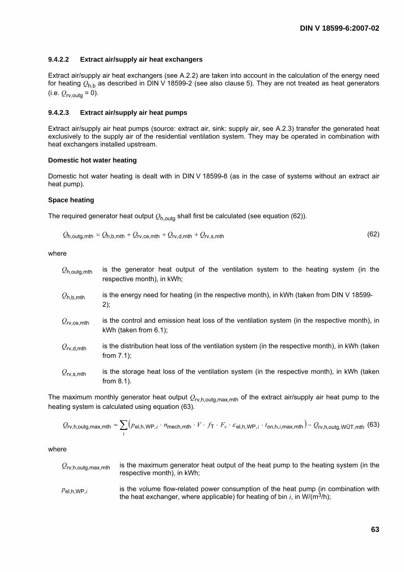
DIN V 18599-6:2007-02
63
9.4.2.2 Extract air/supply air heat exchangers
Extract air/supply air heat exchangers (see A.2.2) are taken into account in the calculation of the energy need for heating Qh,b as described in DIN V 18599-2 (see also clause 5). They are not treated as heat generators (i.e. Qrv,outg = 0).
9.4.2.3 Extract air/supply air heat pumps
Extract air/supply air heat pumps (source: extract air, sink: supply air, see A.2.3) transfer the generated heat exclusively to the supply air of the residential ventilation system. They may be operated in combination with heat exchangers installed upstream.
Domestic hot water heating
Domestic hot water heating is dealt with in DIN V 18599-8 (as in the case of systems without an extract air heat pump).
Space heating
The required generator heat output Qh,outg shall first be calculated (see equation (62)).
mths,rv,mthd,rv,mthce,rv,mthb,h,mthoutg,h, QQQQQ +++= (62)
where
Qh,outg,mth is the generator heat output of the ventilation system to the heating system (in the respective month), in kWh;
Qh,b,mth is the energy need for heating (in the respective month), in kWh (taken from DIN V 18599-2);
Qrv,ce,mth is the control and emission heat loss of the ventilation system (in the respective month), in kWh (taken from 6.1);
Qrv,d,mth is the distribution heat loss of the ventilation system (in the respective month), in kWh (taken from 7.1);
Qrv,s,mth is the storage heat loss of the ventilation system (in the respective month), in kWh (taken from 8.1).
The maximum monthly generator heat output Qrv,h,outg,max,mth of the extract air/supply air heat pump to the heating system is calculated using equation (63).
( ) mthWÜT,outg,,hrv,mthmax,,h,on,WP,h,el,Tmthmech,WP,h,el,mthmax,outg,,hrv, QtFfVnpQi
iivi −⋅⋅⋅⋅⋅⋅= ∑ ε (63)
where
Qrv,h,outg,max,mth is the maximum generator heat output of the heat pump to the heating system (in the respective month), in kWh;
pel,h,WP,i is the volume flow-related power consumption of the heat pump (in combination with the heat exchanger, where applicable) for heating of bin i, in W/(m3/h);

DIN V 18599-6:2007-02
64
nmech,mth is the mean ventilation system-driven air change rate (in the respective month), in h–1;
V is the net volume (see DIN V 18599-2), in m3;
fT is the correction factor for extract air temperature deviations from Table 17;
fv is the correction factor for air volume flow deviations from Table 18;
εel,h,WP,i is the performance coefficient of the heat pump (in combination with the heat exchanger, where applicable) for heating in bin i;
ton,h,i,max,mth is the maximum operating time of the heat pump for heating in bin i (in the respective month) from Table 19, in h/mth;
Qrv,h,outg,WÜT,mth is the generator heat output of any heat exchanger which may be installed upstream, (in the respective month) obtained from equation (64), in kWh.
The correction factor fv for air volume flow deviations takes into account adjustments to the actual air volume flow and can be taken from Table 18.
Table 18 — Correction factor fv for air volume flow deviations
Mean operating volume flow Maximum operating volume flow
Symbol Unit Value
30 % 0,71
40 % 0,79
50 % 0,86
60 % 0,93
70 % 1,0
80 % 1,09
90 %
fv –
1,18
The performance coefficient of the extract air/supply air heat pump used for heating εel,h,WP is tested in accordance with DIN EN 14511-2 and DIN EN 14511-3 and, where applicable, in combination with the extract air/supply air heat exchanger installed upstream (deviating test conditions for national proof of suitability: extract air temperature 21 °C, humidity of extract air 36 %, 46 %, 56 %/external air temperatures –3 °C, 4 °C, 10 °C; humidity of external air 80 %). If the extract air temperatures differ from those given above, the performance coefficient is corrected by applying the factor fT.
If parameters other than the performance coefficient εel,h,WP,i are used for assessing the extract air heat pump, then these shall be converted accordingly, taking any deviating test conditions into account.
The temperature classes (bins)i are determined as a function of the heat pump test conditions (external temperatures). The maximum monthly operating time of the extract air/supply air heat pump in bins i for measurements taken at ϑe = –3 °C/+4 °C/+10 °C with average climatic conditions is given in Table 19. If the heat pump is tested at different temperatures and with different parameters, the monthly operating times shall be adjusted accordingly.

DIN V 18599-6:2007-02
65
Table 19 — Maximum monthly operating times ton,h,i,max,mth of the extract air/supply air heat pumps in bins i (in the respective month), in h
Month Jan Feb Mar Apr May June July Aug Sept Oct Nov Dec
Bin 1 Measuring temp.:
ϑe = –3 °C
Range: ϑe ≤ 0 °C
425 200 81 19 0 0 0 0 0 10 64 214
Bin 2 Measuring temp.:
ϑe = +4 °C
Range: 0 °C < ϑe < 7 °C
312 468 500 205 141 4 0 0 82 178 498 484
Bin 3 Measuring temp.:
(e = +10 °C Range:
7 °C ( (e < 15 °C
7 4 163 389 342 326 227 195 312 500 147 46
Extract air/supply air heat exchangers and ground/supply air heat exchangers are generally taken into account when calculating the energy need for heating according to DIN V 18599-2 (see also clause 5) and they are not treated as heat generators. If, however, heat exchangers are combined with extract air heat pumps, then the contribution of the heat exchangers towards the ventilation system generator heat output needs to be determined. This is done using the monthly generator heat output of the heat exchanger obtained from equation (64).
Qrv,h,outg,WÜT,mth = nmech,mth ⋅ V ⋅ ηWÜT,mth ⋅ (ϑex ϑe,mth) ⋅ trv,mech,mth ⋅ trv,mech,day ⋅ Cp,a ⋅ ρa (64)
where
nmech,mth is the mean ventilation system-driven air change rate (in the respective month), in h–1;
V is the net volume in accordance with DIN V 18599-2, in m3;
ηWÜT,mth is the overall efficiency of heat recovery by the heat exchanger (in the respective month);
ϑex is the mean extract air temperature, in °C;
ϑe,mth is the average external temperature (in the respective month) in °C (taken from DIN V 18599-10);
trv,mth,mech is the total operating time of the ventilation system per month (see Table 6), in d;
trv,day,mech is the total daily operating time of the ventilation system (see Table 6), in h;
Cp,a is the specific heat capacity of air, in kJ/(kg · K);
ρa is the density of air, in kg/m3.

DIN V 18599-6:2007-02
66
Here, cp,a · ρa = 1,22 kJ/(m3 ⋅ K) = 0,34 Wh/(m3 · K) can be used.
If no heat exchanger is installed, Qrv,h,outg,WÜT,mth is equal to zero. In principle, the monthly generator heat output of the heat exchangers can be determined using the values from DIN V 18599-2 (difference between the energy need for heating with and without a heat exchanger) as an alternative, but then the value as given in DIN V 18599-2 has to be corrected.
A distinction shall be made between two different cases, a) and b), when comparing the required generator heat output for space heating Qh,outg,mth obtained from equation (62) and the maximum generator heat output of the extract air/supply air heat pump for space heating Qrv,h,outg,max,mth obtained from equation (63).
a) Qh,outg,mth > Qrv,h,outg,max,mth (heat pump meets only part of the heat demand)
In which case:
mthmax,outg,h,rv,mthoutg,h,rv, QQ = (65)
where
Qrv,h,outg,mth is the generator heat output of the heat pump to the heating system (in the respective month), in kWh;
Qrv,h,outg,max,mth is the maximum generator heat output of the heat pump to the heating system (in the respective month) see equation (63), in kWh.
mthoutg,h,rv,mthoutg,h,*
mthb,h, QQQ −= (66)
where
Q*h,b,mth is the residual energy need for heating (in the respective month), in kWh, (to be used in the calculations in DIN V 18599-5, or, if electric heating is used, to be used directly in DIN V 18599-1);
Qh,outg,mth is the generator heat output to the heating system (in the respective month), in kWh, (taken from equation (62).
∑∑ =i
ii
i tt mthmax,,h,on,mth,h,on, (67)
where
Σton,h,i,mth is the total operating time of the heat pump for heating (in the respective month), in h;
ton,h,i,max,mth is the maximum operating time of the heat pump for heating in bin i (in the respective month) as given in Table 19, in h.
b) Qh,outg,mth ≤ Qrv,h,outg,max,mth (heat pump can meet the total heat demand)
In which case:
mthoutg,h,mthoutg,h,rv, QQ = (in the respective month), in kWh (68)

DIN V 18599-6:2007-02
67
0*mthb,h, =Q (in the respective month), in kWh (69)
∑∑ ⋅=i
ii
i tQ
Qt ,max,mthon,h,
thoutg,max,mrv,h,
outg,mthrv,h,,mthon,h, (in the respective month), in h (70)
The annual generator heat output of the extract air/supply air heat pump to the heating system is calculated by adding up the values for the whole year (see equation (71)).
∑= mthh,outg,h,rv,aoutg,h,v,r QQ (71)
where
Qrv,h,outg,a is the annual generator heat output of the heat pump to the heating system, in kWh;
Qrv,h,outg,mth is the generator heat output of the heat pump to the heating system (in the respective month), in kWh.
Default values
Correction factor for extract air temperature deviations: fr = 1,0
Correction factor for air volume flow deviations: fv = 1,0
Mean monthly ventilation system-driven air change rate nmech,mth = 0,4 h–1
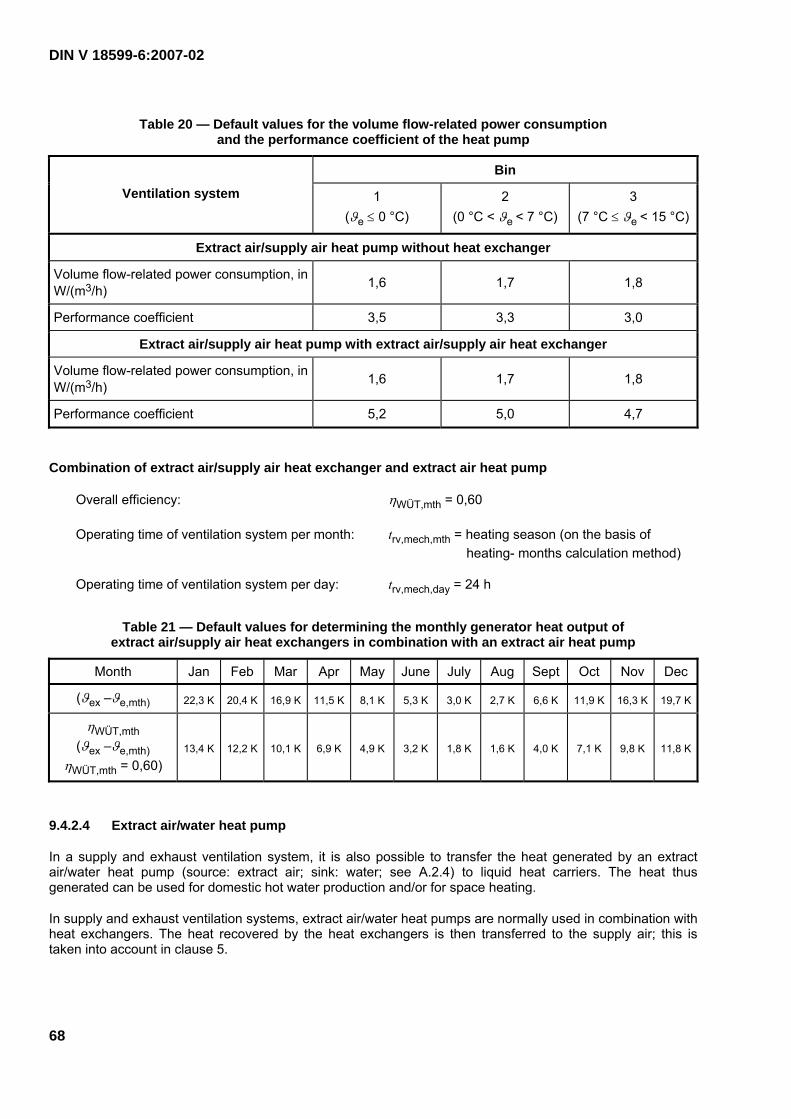
DIN V 18599-6:2007-02
68
Table 20 — Default values for the volume flow-related power consumption and the performance coefficient of the heat pump
Bin
Ventilation system 1 (ϑe ≤ 0 °C)
2 (0 °C < ϑe < 7 °C)
3 (7 °C ≤ ϑe < 15 °C)
Extract air/supply air heat pump without heat exchanger
Volume flow-related power consumption, in W/(m3/h) 1,6 1,7 1,8
Performance coefficient 3,5 3,3 3,0
Extract air/supply air heat pump with extract air/supply air heat exchanger
Volume flow-related power consumption, in W/(m3/h) 1,6 1,7 1,8
Performance coefficient 5,2 5,0 4,7
Combination of extract air/supply air heat exchanger and extract air heat pump
Overall efficiency: ηWÜT,mth = 0,60
Operating time of ventilation system per month: trv,mech,mth = heating season (on the basis of heating- months calculation method)
Operating time of ventilation system per day: trv,mech,day = 24 h
Table 21 — Default values for determining the monthly generator heat output of extract air/supply air heat exchangers in combination with an extract air heat pump
Month Jan Feb Mar Apr May June July Aug Sept Oct Nov Dec
(ϑex –ϑe,mth) 22,3 K 20,4 K 16,9 K 11,5 K 8,1 K 5,3 K 3,0 K 2,7 K 6,6 K 11,9 K 16,3 K 19,7 K
ηWÜT,mth (ϑex –ϑe,mth)
ηWÜT,mth = 0,60) 13,4 K 12,2 K 10,1 K 6,9 K 4,9 K 3,2 K 1,8 K 1,6 K 4,0 K 7,1 K 9,8 K 11,8 K
9.4.2.4 Extract air/water heat pump
In a supply and exhaust ventilation system, it is also possible to transfer the heat generated by an extract air/water heat pump (source: extract air; sink: water; see A.2.4) to liquid heat carriers. The heat thus generated can be used for domestic hot water production and/or for space heating.
In supply and exhaust ventilation systems, extract air/water heat pumps are normally used in combination with heat exchangers. The heat recovered by the heat exchangers is then transferred to the supply air; this is taken into account in clause 5.

DIN V 18599-6:2007-02
69
Domestic hot water
The generator heat output Qw,outg required for domestic hot water is calculated as described in DIN V 18599-8, taking into consideration any values previously subtracted to account for any regenerative heat gains.
The maximum monthly generator heat output Qrv,w,outg,max,mth of the extract air/water heat pump used for domestic hot water is calculated using equation (72).
mthoutg,WÜT,,hrv,mthmax,on,w,tTmth,ABLmech,el,w,WPmthmax,outg,,rv, QtCOPfVnpQ w −⋅⋅⋅⋅⋅= (72)
where
Qrv,w,outg,max,mth is the maximum generator heat output of the heat pump to the domestic hot water heating system (in the respective month), in kWh;
pel,w,WP is the volume flow-related power consumption of the heat pump for domestic hot water, in W/(m3/h);
nmech,ABL,mth is the mean ventilation system-driven extract air change rate (in the respective month) obtained from equation (42), in h–1;
V is the net volume in accordance with DIN V 18599-2, in m3;
fT is the correction factor for extract air temperature deviations from Table 17;
COPt is the coefficient of performance of the heat pump for domestic hot water;
ton,w,max,mth is the maximum operating time of the heat pump for domestic hot water (in the respective month), in h;
Qrv,h,outg,WÜT,mth is the generator heat output of the heat exchangers (in the respective month) obtained from equation (64), in kWh.
The coefficient of performance COPt of the heat pump used for domestic hot water is tested according to DIN EN 255-3. (Deviating test conditions for national proof of suitability: extract air temperature 21 °C, humidity of extract air 56 %, heat pump supply temperature 40 °C). If the extract air temperatures differ from the above, the coefficient of performance is corrected by applying the factor fT. Where ventilation systems form an integral unit, COPt also takes into account the recovered thermal energy of the auxiliary systems (e.g. fans and controls). These do not have to be calculated separately.
If parameters other than the coefficient of performance COPt are used for assessing the extract air heat pump, then these shall be converted accordingly, taking into account any deviating test conditions.
The maximum monthly operating time ton,w,max,mth of the extract air/water heat pump corresponds to the total operating time (trv,mth,mech ⋅ trv,day,mech) of the ventilation system as given in Table 6.
Extract air/supply air heat exchangers and ground/supply air heat exchangers are normally taken into account when calculating the energy need for heating according to DIN V 18599-2 (see also clause 5), and they are not treated as heat generators. If, however, heat exchangers are combined with extract air heat pumps, then the contribution of the heat exchangers towards the generator heat output of the ventilation system shall be determined. This is done using the monthly generator heat output of the heat exchanger obtained from equation (64).

DIN V 18599-6:2007-02
70
A distinction shall be made between two different cases, a) and b), when comparing the required generator heat output for domestic hot water heating Qw,outg,mth determined according to DIN 18599-8 and the maximum generator heat output of the extract air/water heat pump for domestic hot water heating Qrv,w,outg,max,mth obtained from equation (72).
a) Qw,outg,mth > Qrv,w,outg,max,mth (heat pump supplies only part of the heat required for domestic hot water)
This is calculated using equations (47) to (49).
b) Qw,outg,mth ≤ Qrv,w,outg,max,mth (heat pump supplies the total heat required for domestic hot water)
This is calculated using equations (50) to (52).
The annual generator heat output of the extract air/water heat pump for domestic hot water is calculated by adding together the values for the whole year (see equation (73)).
∑= mthoutg,rv,w,aoutg,rv,w, QQ (73)
where
Qrv,w,outg,a is the annual generator heat output of the heat pump to the domestic hot water heating system, in kWh;
Qrv,w,outg,mth is the generator heat output of the heat pump to the domestic hot water heating system (in the respective month), in kWh.
Space heating
The required generator heat output Qh,outg for space heating purposes is calculated as described in DIN V 18599-5, taking into consideration any values previously subtracted to account for any regenerative heat gains.
The maximum monthly generator heat output Qrv,h,outg,max,mth of the extract air/water heat pump to the space heating system is calculated using equation (74).
( ) mthoutg,rv,w,mthh,g,on,h,WPel,Tmthmech,ABL,h,WPel,mthmax,outg,h,rv, QtffVnpQ −⋅⋅⋅⋅⋅⋅= εϑ (74)
where
Qrv,h,outg,max,mth is the maximum generator heat output of the heat pump to the heating system (in the respective month), in kWh;
pel,h,WP is the volume flow-related power consumption of the heat pump for heating, in W/(m3/h);
nmech,ABL,mth is the mean ventilation system-driven extract air change rate (in the respective month) obtained from equation (42), in h–1;
V is the net volume in accordance with DIN V 18599-2, in m3;
fT is the correction factor for extract air temperature deviations from Table 17;
fϑ is the correction factor for heating circuit temperature deviations from Table 17;
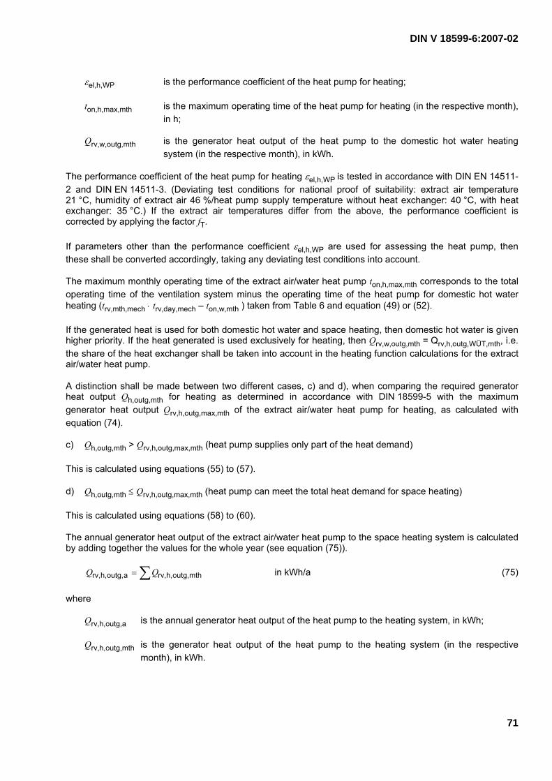
DIN V 18599-6:2007-02
71
εel,h,WP is the performance coefficient of the heat pump for heating;
ton,h,max,mth is the maximum operating time of the heat pump for heating (in the respective month), in h;
Qrv,w,outg,mth is the generator heat output of the heat pump to the domestic hot water heating system (in the respective month), in kWh.
The performance coefficient of the heat pump for heating εel,h,WP is tested in accordance with DIN EN 14511-2 and DIN EN 14511-3. (Deviating test conditions for national proof of suitability: extract air temperature 21 °C, humidity of extract air 46 %/heat pump supply temperature without heat exchanger: 40 °C, with heat exchanger: 35 °C.) If the extract air temperatures differ from the above, the performance coefficient is corrected by applying the factor fT.
If parameters other than the performance coefficient εel,h,WP are used for assessing the heat pump, then these shall be converted accordingly, taking any deviating test conditions into account.
The maximum monthly operating time of the extract air/water heat pump ton,h,max,mth corresponds to the total operating time of the ventilation system minus the operating time of the heat pump for domestic hot water heating (trv,mth,mech ⋅ trv,day,mech – ton,w,mth ) taken from Table 6 and equation (49) or (52).
If the generated heat is used for both domestic hot water and space heating, then domestic hot water is given higher priority. If the heat generated is used exclusively for heating, then Qrv,w,outg,mth = Qrv,h,outg,WÜT,mth, i.e. the share of the heat exchanger shall be taken into account in the heating function calculations for the extract air/water heat pump.
A distinction shall be made between two different cases, c) and d), when comparing the required generator heat output Qh,outg,mth for heating as determined in accordance with DIN 18599-5 with the maximum generator heat output Qrv,h,outg,max,mth of the extract air/water heat pump for heating, as calculated with equation (74).
c) Qh,outg,mth > Qrv,h,outg,max,mth (heat pump supplies only part of the heat demand)
This is calculated using equations (55) to (57).
d) Qh,outg,mth ≤ Qrv,h,outg,max,mth (heat pump can meet the total heat demand for space heating)
This is calculated using equations (58) to (60).
The annual generator heat output of the extract air/water heat pump to the space heating system is calculated by adding together the values for the whole year (see equation (75)).
∑= mthoutg,h,rv,aoutg,h,rv, QQ in kWh/a (75)
where
Qrv,h,outg,a is the annual generator heat output of the heat pump to the heating system, in kWh;
Qrv,h,outg,mth is the generator heat output of the heat pump to the heating system (in the respective month), in kWh.
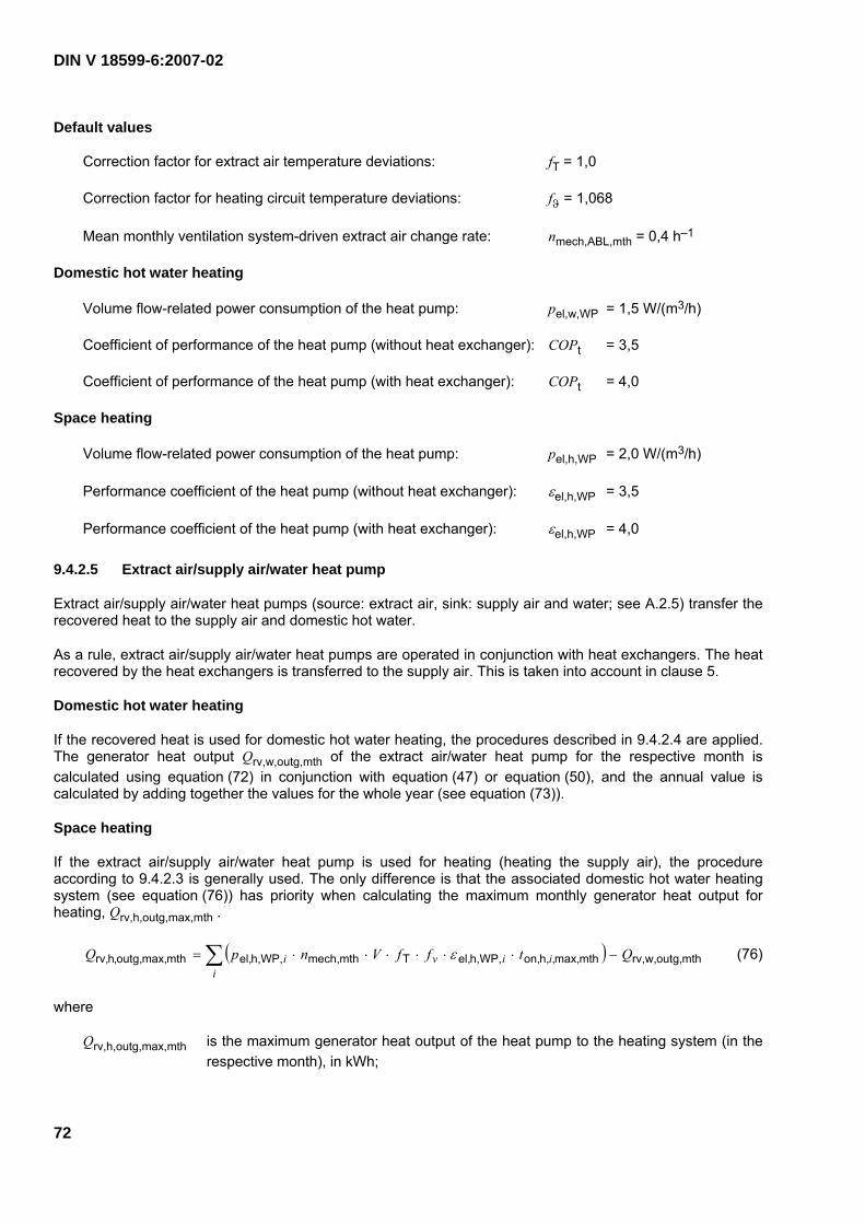
DIN V 18599-6:2007-02
72
Default values
Correction factor for extract air temperature deviations: fT = 1,0
Correction factor for heating circuit temperature deviations: fϑ = 1,068
Mean monthly ventilation system-driven extract air change rate: nmech,ABL,mth = 0,4 h–1
Domestic hot water heating
Volume flow-related power consumption of the heat pump: pel,w,WP = 1,5 W/(m3/h)
Coefficient of performance of the heat pump (without heat exchanger): COPt = 3,5
Coefficient of performance of the heat pump (with heat exchanger): COPt = 4,0
Space heating
Volume flow-related power consumption of the heat pump: pel,h,WP = 2,0 W/(m3/h)
Performance coefficient of the heat pump (without heat exchanger): εel,h,WP = 3,5
Performance coefficient of the heat pump (with heat exchanger): εel,h,WP = 4,0
9.4.2.5 Extract air/supply air/water heat pump
Extract air/supply air/water heat pumps (source: extract air, sink: supply air and water; see A.2.5) transfer the recovered heat to the supply air and domestic hot water.
As a rule, extract air/supply air/water heat pumps are operated in conjunction with heat exchangers. The heat recovered by the heat exchangers is transferred to the supply air. This is taken into account in clause 5.
Domestic hot water heating
If the recovered heat is used for domestic hot water heating, the procedures described in 9.4.2.4 are applied. The generator heat output Qrv,w,outg,mth of the extract air/water heat pump for the respective month is calculated using equation (72) in conjunction with equation (47) or equation (50), and the annual value is calculated by adding together the values for the whole year (see equation (73)).
Space heating
If the extract air/supply air/water heat pump is used for heating (heating the supply air), the procedure according to 9.4.2.3 is generally used. The only difference is that the associated domestic hot water heating system (see equation (76)) has priority when calculating the maximum monthly generator heat output for heating, Qrv,h,outg,max,mth .
( ) mthoutg,rv,w,mthmax,,h,on,h,WP,el,Tmthmech,h,WP,el,mthmax,outg,,hrv, QtffVnpQi
iivi −⋅⋅⋅⋅⋅⋅= ∑ ε (76)
where
Qrv,h,outg,max,mth is the maximum generator heat output of the heat pump to the heating system (in the respective month), in kWh;

DIN V 18599-6:2007-02
73
pel,h,WP,i is the volume flow-related power consumption of the heat pump (in combination with the heat exchanger, where applicable) for heating in bin i, in W/(m3/h);
nmech,mth is the mean ventilation system-driven air change rate (in the respective month), in h–1;
V is the net volume in accordance with DIN V 18599-2, in m3;
fT is the correction factor for extract air temperature deviations from Table 17;
fv is the correction factor for air volume flow deviations from Table 18;
εel,h,WP,i is the performance coefficient of the heat pump (in combination with the heat exchanger, where applicable) for heating in bin i;
ton,h,i,max,mth is the maximum monthly operating time of the heat pump for heating in bin i as given in Table 19, in h;
Qrv,w,outg,mth is the generator heat output of the heat pump to the domestic hot water heating system (in the respective month), in accordance with 9.4.2.4, in kWh.
The performance coefficient of the heat pump for heating, εel,h,WP, is tested in accordance with DIN EN 14511-2 and DIN EN 14511-3. (Deviating test conditions for national proof of suitability: extract air temperature 21 °C, humidity of extract air 36 %, 46 %, 56 %/external air temperature –3 °C, 4 °C, 10 °C; humidity of external air 80 %.) If the extract air temperatures differ from the above, the performance coefficient is corrected by applying the factor fT.
If parameters other than the performance coefficient εel,h,WP,i are used for assessing the heat pump, these shall be converted accordingly, taking into account the possible deviations of the test conditions.
The generator heat output Qrv,h,outg,mth of the extract air/supply air/water heat pump is calculated using equation (76) in conjunction with equation (65) or equation (50). The annual output is calculated by adding up the values for the whole year (see equation (71)).
Default values
The default values given in 9.4.2.4 can be used for domestic hot water heating calculations, those given in 9.4.2.3 can be used for space heating calculations.
9.4.3 Air heating systems
Air heating systems (see A.3) are heating systems which supply heat to a zone using only air as the heat carrier. Air heating systems have at least one heat generator (e.g. an extract air heat pump); they may also be provided with a heat exchanger.
If the air heating system includes heat exchangers and/or heat pumps, the assessment is initially carried out using the method described in 9.4.2.
Equation (77) is used for the reheating coil.
Qrv,h,outg,NH,mth = (Qh,b + Qh,ce + Qh,d + Qh,s + Qrv,ce + Qrv,d + Qrv,s) – (Qh,outg,reg + Qrv,h,outg) (77)
where

DIN V 18599-6:2007-02
74
Qrv,h,outg,NH,mth is the generator heat output of the reheating coils to the heating system (in the respective month), in kWh;
Qh,b is the energy need for heating of the zone (in the respective month), in kWh;
Qh,ce are the control and emission heat losses of the heating system (in the respective month), in kWh;
Qh,d is the distribution heat loss of the heating system (in the respective month), in kWh;
Qh,s is the storage heat loss of the heating system (in the respective month), in kWh;
Qrv,ce is the control and emission heat loss of the residential ventilation system (in the respective month), in kWh;
Qrv,d is the distribution heat loss of the residential ventilation system (in the respective month), in kWh;
Qrv,s is the storage heat loss of the residential ventilation system (in the respective month), in kWh;
Qh,outg,reg are the heat gains from regenerative energy sources (in the respective month), in kWh;
Qrv,h,outg is the generator heat output of the heat pump to the heating system (in the respective month), in kWh.
For air heating systems with electric reheating coils, Qh,ce = 0, Qh,d = 0 and Qh,s = 0. The values of Qh,ce, Qh,d and Qh,s of air heating systems with water-filled reheating coils are calculated as described in DIN V 18599-5.
For air heating systems with extract air/supply air heat pumps, Qrv,s = 0.
The annual generator heat output of the reheating coils of an air heating system is determined by adding together the values for the whole year (see equation (78)).
∑= mthNH,outg,h,rv,aNH,outg,h,rv, QQ (78)
where
Qrv,h,outg,NH,a is the annual generator heat output of the reheating coils to the space heating system, in kWh;
Qrv,h,outg,NH,mth is the generator heat output of the reheating coils to the space heating system (in the respective month), in kWh.
Default values
a) Electric reheating coil:
monthly heat loss due to control and emission for heating: Qh,ce = 0 kWh
monthly heat loss of distribution for heating: Qh,d = 0 kWh
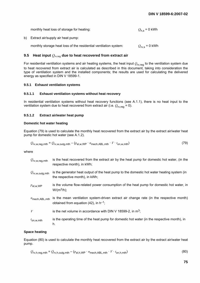
DIN V 18599-6:2007-02
75
monthly heat loss of storage for heating: Qh,s = 0 kWh
b) Extract air/supply air heat pump:
monthly storage heat loss of the residential ventilation system: Qrv,s = 0 kWh
9.5 Heat input Qrv,reg due to heat recovered from extract air
For residential ventilation systems and air heating systems, the heat input Qrv,reg to the ventilation system due to heat recovered from extract air is calculated as described in this document, taking into consideration the type of ventilation system and the installed components; the results are used for calculating the delivered energy as specified in DIN V 18599-1.
9.5.1 Exhaust ventilation systems
9.5.1.1 Exhaust ventilation systems without heat recovery
In residential ventilation systems without heat recovery functions (see A.1.1), there is no heat input to the ventilation system due to heat recovered from extract air (i.e. Qrv,reg = 0).
9.5.1.2 Extract air/water heat pump
Domestic hot water heating
Equation (79) is used to calculate the monthly heat recovered from the extract air by the extract air/water heat pump for domestic hot water (see A.1.2).
Qrv,w,reg,mth = Qrv,w,outg,mth – (pel,w,WP · nmech,ABL,mth · V · ton,w,mth) (79)
where
Qrv,w,reg,mth is the heat recovered from the extract air by the heat pump for domestic hot water, (in the respective month), in kWh;
Qrv,w,outg,mth is the generator heat output of the heat pump to the domestic hot water heating system (in the respective month), in kWh;
pel,w,WP is the volume flow-related power consumption of the heat pump for domestic hot water, in W/(m3/h);
nmech,ABL,mth is the mean ventilation system-driven extract air change rate (in the respective month) obtained from equation (42), in h–1;
V is the net volume in accordance with DIN V 18599-2, in m3;
ton,w,mth is the operating time of the heat pump for domestic hot water (in the respective month), in h.
Space heating
Equation (80) is used to calculate the monthly heat recovered from the extract air by the extract air/water heat pump.
Qrv,h,reg,mth = Qrv,h,outg,mth – (pel,h,WP · nmech,ABL,mth · V · ton,h,mth) (80)

DIN V 18599-6:2007-02
76
where
Qrv,h,reg,mth is the heat recovered from the extract air by the heat pump for heating (in the respective month), in kWh;
Qrv,h,outg,mth is the generator heat output of the heat pump to the heating system (in the respective month), in kWh;
pel,h,WP is the volume flow-related power consumption of the heat pump for heating, in W/(m3/h);
nmech,ABL,mth is the mean ventilation system-driven extract air change rate (in the respective month) obtained from equation (42), in h–1;
V is the net volume in accordance with DIN V 18599-2, in m3;
ton,h,mth is the operating time of the heat pump for heating (in the respective month), in h.
The annual quantity of heat recovered from the extract air by the extract air/water heat pump is calculated by adding together the values for domestic hot water and heating for the whole year (see equation (81)).
( )∑ += mthreg,h,v,rmthreg,w,v,rareg,rv, QQQ (81)
where
Qrv,reg,a is the heat recovered annually from the extract air by the heat pump, in kWh;
Qrv,w,reg,mth is the heat recovered from the extract air by the heat pump for domestic hot water, (in the respective month), in kWh;
Qrv,h,reg,mth is the heat recovered from the extract air by the heat pump for heating (in the respective month), in kWh.
Default values
The default values given in 9.4.1.2 can be used.
9.5.2 Supply and exhaust ventilation systems
9.5.2.1 Supply and exhaust ventilation systems without heat recovery
In residential ventilation systems without heat recovery functions (see A.2.1), there is no input to the ventilation system due to heat recovered from extract air (i.e. Qrv,reg = 0).
9.5.2.2 Extract air/supply air heat exchangers
Extract air/supply air heat exchangers (see A.2.2) are taken into account when calculating the energy need for heating Qh,b as described in DIN V 18599-2 (see also clause 5) They are not treated as heat generators (i.e. Qrv,reg = 0).

DIN V 18599-6:2007-02
77
9.5.2.3 Extract air/supply air heat pump
Space heating
Equation (82) is used to calculate the monthly heat recovered from the extract air by the extract air/supply air heat pump (see A.2.3).
( )∑ ⋅⋅⋅−=i
ii tVnpQQ mth,h,on,mthmech,WP,h,el,mthoutg,,hrv,mthr,reg,h,rv, (82)
where
Qrv,h,reg,mth is the heat recovered from the extract air by the heat pump (in the respective month), in kWh;
Qrv,h,outg,mth is the generator heat output of the heat pump (in the respective month), in kWh;
pel,h,WP,i is the volume flow-related power consumption of the heat pump in bin i, in W/(m3/h);
nmech,mth is the mean ventilation system-driven air change rate (in the respective month), in h–1;
V is the net volume in accordance with DIN V 18599-2, in m3;
ton,h,i,mth is the operating time of the heat pump in bin i (in the respective month), in h.
The annual quantity of heat recovered by the extract air/supply air heat pump is calculated by adding together the heat recovery values for the whole year (see equation (83)).
∑= mthreg,h,rv,a,regrv, QQ (83)
where
Qrv,reg,a is the heat recovered annually from the extract air by the heat pump, in kWh;
Qrv,h,reg,mth is the heat recovered from the extract air by the heat pump (in the respective month), in kWh.
Default values
The default values given in 9.4.2.3 can be used.
9.5.2.4 Extract air/water heat pump
Domestic hot water heating
Equation (84) is used to calculate the monthly heat recovered from the extract air by the extract air/water heat pump (see A.2.4) for domestic hot water.
Qrv,w,reg,mth = Qrv,w,outg,mth – (pel,w,WP · nmech,ABL,mth · V · ton,w,mth) (84)
where
Qrv,w,reg,mth is the heat recovered from the extract air by the heat pump for domestic hot water (in the respective month), in kWh;

DIN V 18599-6:2007-02
78
Qrv,w,outg,mth is the generator heat output of the heat pump to the domestic hot water heating system (in the respective month), in kWh;
pel,w,WP is the volume flow-related power consumption of the heat pump for domestic hot water, in W/(m3/h);
nmech,ABL,mth is the mean ventilation system-driven extract air change rate (in the respective month) obtained from equation (42), in h–1;
V is the net volume in accordance with DIN V 18599-2, in m3;
ton,w,mth is the operating time of the heat pump for domestic hot water (in the respective month), in h.
Space heating
Equation (85) is used to calculate the monthly heat recovered from the extract air by the extract air/water heat pump for heating.
Qrv,h,reg,mth = Qrv,h,outg,mth – (pel,h,WP · nmech,ABL,mth · V · ton,h,mth) (85)
where
Qrv,h,reg,mth is the heat recovered from the extract air by the heat pump for heating (in the respective month), in kWh;
Qrv,h,outg,mth is the generator heat output of the heat pump to the heating system (in the respective month), in kWh;
pel,h,WP is the volume flow-related power consumption of the heat pump for heating, in W/(m3/h);
nmech,ABL,mth is the mean ventilation system-driven extract air change rate (in the respective month) obtained from equation (42), in h–1;
V is the net volume in accordance with DIN V 18599-2, in m3;
ton,h,mth is the operating time of the heat pump for heating (in the respective month), in h.
The annual quantity of heat recovered by the extract air/water heat pump is calculated by adding together the heat recovery values for hot water heating and heating for the whole year (see equation (86)).
( )∑ += mthreg,h,rv,mthreg,w,rv,areg,rv, QQQ (86)
where
Qrv,reg,a is the heat recovered annually from the extract air by the heat pump, in kWh;
Qrv,w,reg,mth is the heat recovered from the extract air by the heat pump for domestic hot water (in the respective month), in kWh;
Qrv,h,reg,mth is the heat recovered from the extract air by the heat pump for heating (in the respective month), in kWh.

DIN V 18599-6:2007-02
79
Default values
The default values given in 9.4.2.4 can be used.
9.5.2.5 Extract air/supply air/water heat pump
Domestic hot water heating
Equation (84) is used to calculate the monthly heat recovered from the extract air by the extract air/supply air/water heat pump (see A.2.5) for domestic hot water.
Space heating
Equation (82) is used to calculate the monthly heat recovered from the extract air by the extract air/supply air/water heat pump for heating.
The annual quantity of heat recovered by the extract air/supply air/water heat pump is calculated by adding together the heat recovery values for domestic hot water and heating for the whole year (see equation (86)).
Default values
The default values given in 9.4.2.5 can be used.
9.5.3 Air heating systems
Air heating systems (see A.3) are systems which supply heat to a zone using only air as the heat carrier. Air heating systems have at least one heat generator (e.g. an extract air heat pump), they may also have a supplementary heat exchanger.
If an air heating system is equipped with extract air heat pumps, the ventilation system components actually installed are taken into consideration when calculating the monthly heat recovery according to 9.5.2.
For air heating systems without extract air heat pumps, Qrv,reg = 0.
Default values
The default values given in 9.4.2 can be used.

DIN V 18599-6:2007-02
80
Annex A (normative)
Ventilation systems
A.1 Exhaust ventilation systems
A.1.1 Exhaust ventilation systems without heat recovery
Key AB extract air FO exhaust air
General boundary conditions for determining the generation heat losses Qrv,g
Exhaust ventilation systems without heat recovery
Qrv,g,mth 0
General boundary conditions for determining the generation heat gains Ql,rv,g
Exhaust ventilation systems without heat recovery
Ql,rv,g,mth 0
General boundary conditions for determining the auxiliary energy for generation Qrv,g,aux
Exhaust ventilation systems without heat recovery
QVent,aux,mth see equation (41)
QReg,aux,mth see equation (43)
QVorw,aux,mth 0
General boundary conditions for determining the generator heat output Qrv,outg
Exhaust ventilation systems without heat recovery
Qrv,outg,mth 0
�
Figure A.1 — Exhaust ventilation system with single-room fans

DIN V 18599-6:2007-02
81
General boundary conditions for determining the heat recovered from extract air Qrv,reg
Exhaust ventilation systems without heat recovery
Qrv,reg,mth 0
Figure A.2 — Exhaust ventilation system with central fan

DIN V 18599-6:2007-02
82
A.1.2 Exhaust ventilation systems with extract air/water heat pump
Key FO exhaust air AB extract air
SH space heating DHW domestic hot water
General boundary conditions for determining the generation heat losses Qrv,g
Exhaust ventilation systems with extract air/water heat pump
Qrv,g,mth see equation (35)
General boundary conditions for determining the generation heat gains Ql,rv,g
Exhaust ventilation systems with extract air/water heat pump
Ql,rv,g,mth see equation (39)
General boundary conditions for determining the auxiliary energy for generation Qrv,g,aux
Exhaust ventilation systems with extract air/water heat pump
QVent,aux,mth see equation (41)
QReg,aux,mth see equation (43)
QVorw,aux,mth 0
General boundary conditions for determining the generator heat output Qrv,outg
Exhaust ventilation systems with extract air/water heat pump
Qrv,outg,mth DHW: see equations (47) and (50) SH: see equations (55) and (58)
General boundary conditions for determining the heat recovered from extract air Qrv,reg
Exhaust ventilation systems with extract air/water heat pump
Qrv,reg,mth DHW: see equation (79) SH: see equation (80)
Figure A.3 — Exhaust ventilation system with heat pump

DIN V 18599-6:2007-02
83
A.2 Supply and exhaust ventilation systems
A.2.1 Supply and exhaust ventilation systems without heat recovery
Key FO exhaust air AB extract air AU external air ZU supply air
General boundary conditions for determining the generation heat losses Qrv,g
Supply and exhaust ventilation systems without heat recovery
Qrv,g,mth 0
General boundary conditions for determining the generation heat gains Ql,rv,g
Supply and exhaust ventilation systems without heat recovery
Ql,rv,g,mth 0
General boundary conditions for determining the auxiliary energy for generation Qrv,g,aux
Supply and exhaust ventilation systems without heat recovery
QVent,aux,mth see equation (41)
QReg,aux,mth see equation (43)
QVorw,aux,mth 0
General boundary conditions for determining the generator heat output Qrv,outg
Supply and exhaust ventilation systems without heat recovery
Qrv,outg,mth 0
General boundary conditions for determining the heat recovered from extract air Qrv,reg
Supply and exhaust ventilation systems without heat recovery
Qrv,reg,mth 0
Figure A.4 — Supply and exhaust ventilation system without heat recovery

DIN V 18599-6:2007-02
84
A.2.2 Supply and exhaust ventilation systems with extract air/supply air heat exchanger
A.2.2.1 Central system
Key AU external air FO exhaust air AB extract air ZU supply air
General boundary conditions for determining the generation heat losses Qrv,g
Supply and exhaust ventilation systems with extract air/supply air heat exchanger
Qrv,g,mth 0
General boundary conditions for determining the generation heat gains Ql,rv,g
Supply and exhaust ventilation systems with extract air/supply air heat exchanger
Ql,rv,g,mth 0
General boundary conditions for determining the auxiliary energy for generation Qrv,g,aux
Supply and exhaust ventilation systems with extract air/supply air heat exchanger
QVent,aux,mth see equation (41)
QReg,aux,mth see equation (43)
QVorw,aux,mth see equation (44)
General boundary conditions for determining the generator heat output Qrv,outg
Supply and exhaust ventilation systems with extract air/supply air heat exchanger
Qrv,outg,mth 0
General boundary conditions for determining the heat recovered from extract air Qrv,reg
Supply and exhaust ventilation systems with extract air/supply air heat exchanger
Qrv,reg,mth 0
�
Figure A.5 — Supply and exhaust ventilation system with extract air/supply air heat exchanger
for a building

DIN V 18599-6:2007-02
85
A.2.2.2 Decentralized (room-wise)
System 1
System 2
Key AU external air FO exhaust air AB extract air ZU supply air
General boundary conditions for determining the generation heat losses Qrv,g
Supply and exhaust ventilation systems with extract air/supply air heat exchanger
Qrv,g,mth 0
General boundary conditions for determining the generation heat gains Ql,rv,g
Supply and exhaust ventilation systems with extract air/supply air heat exchanger
Ql,rv,g,mth 0
General boundary conditions for determining the auxiliary energy for generation Qrv,g,aux
Supply and exhaust ventilation systems with extract air/supply air heat exchanger
QVent,aux,mth see equation (41)
QReg,aux,mth see equation (43)
QVorw,aux,mth see equation (44)
General boundary conditions for determining the generator heat output Qrv,outg
Supply and exhaust ventilation systems with extract air/supply air heat exchanger
Qrv,outg,mth 0
General boundary conditions for determining the heat recovered from extract air Qrv,reg
Supply and exhaust ventilation systems with extract air/supply air heat exchanger
Qrv,reg,mth 0
Figure A.6 — Supply and exhaust ventilation system with extract air/supply air heat exchanger
for a single room

DIN V 18599-6:2007-02
86
A.2.3 Supply and exhaust ventilation systems with extract air/supply air heat pump, with and without heat exchanger
System 1
System 2
Key FO exhaust air AU external air AB extract air ZU supply air
General boundary conditions for determining the generation heat losses Qrv,g
Supply and exhaust ventilation systems with extract air/supply air heat pump
Qrv,g,mth see equation (35)
General boundary conditions for determining the generation heat gains Ql,rv,g
Supply and exhaust ventilation systems with extract air/supply air heat pump
Ql,rv,g,mth see equation (39)
General boundary conditions for determining the auxiliary energy for generation Qrv,g,aux
Supply and exhaust ventilation systems with extract air/supply air heat pump
QVent,aux,mth see equation (41)
QReg,aux,mth see equation (43)
QVorw,aux,mth see equation (44)
General boundary conditions for determining the generator heat output Qrv,outg
Supply and exhaust ventilation systems with extract air/supply air heat pump
Qrv,outg,mth DHW: - SH: see eqns. (65) and (68)
General boundary conditions for determining the heat recovered from extract air Qrv,reg
Supply and exhaust ventilation systems with extract air/supply air heat pump
Qrv,reg,mth DHW: - SH: see equation (82)
�
Figure A.7 — Supply and exhaust ventilation system with extract air/supply air heat pump (with
and without heat exchanger)

DIN V 18599-6:2007-02
87
A.2.4 Supply and exhaust ventilation systems with extract air/water heat pump and with heat exchanger
Key AB extract air SH space heating ZU supply air DHW domestic hot water FO exhaust air AU external air
General boundary conditions for determining the generation heat losses Qrv,g
Supply and exhaust ventilation systems with extract air/water heat pump
Qrv,g,mth see equation (35)
General boundary conditions for determining the generation heat gains Ql,rv,g
Supply and exhaust ventilation systems with extract air/water heat pump
Ql,rv,g,mth see equation (39)
General boundary conditions for determining the auxiliary energy for generation Qrv,g,aux
Supply and exhaust ventilation systems with extract air/water heat pump
QVent,aux,mth see equation (41)
QReg,aux,mth see equation (43)
QVorw,aux,mth see equation (44)
General boundary conditions for determining the generator heat output Qrv,outg
Supply and exhaust ventilation systems with extract air/water heat pump
Qrv,outg,mth DHW: see equations (47) and (50) SH: see equations (55) and (58)
General boundary conditions for determining the heat recovered from extract air Qrv,reg
Supply and exhaust ventilation systems with extract air/water heat pump
Qrv,reg,mth DHW: see equation (84) SH: see equation (85)
Figure A.8 — Supply and exhaust ventilation system with extract air/water heat pump and with
heat exchanger

DIN V 18599-6:2007-02
88
A.2.5 Supply and exhaust ventilation systems with extract air/supply air/water heat pump and heat exchanger
Key AB extract air FO exhaust air AU external air ZU supply air SH space heating DHW domestic hot water
General boundary conditions for determining the generation heat losses Qrv,g
Supply and exhaust ventilation systems with extract air/supply air/water heat pump
Qrv,g,mth see equation (35)
General boundary conditions for determining the generation heat gains Ql,rv,g
Supply and exhaust ventilation systems with extract air/supply air/water heat pump
Ql,rv,g,mth see equation (39)
General boundary conditions for determining the auxiliary energy for generation Qrv,g,aux
Supply and exhaust ventilation systems with extract air/supply air/water heat pump
QVent,aux,mth see equation (41)
QReg,aux,mth see equation (43)
QVorw,aux,mth see equation (44)
General boundary conditions for determining the generator heat output Qrv,outg
Supply and exhaust ventilation systems with extract air/supply air/water heat pump
Qrv,outg,mth DHW: see equations (47) and (50) SH: see equations (65) and (68)
General boundary conditions for determining the heat recovered from extract air Qrv,reg
Supply and exhaust ventilation systems with extract air/supply air/water heat pump
Qrv,reg,mth DHW: see equation (84) SH: see equation (82)
Figure A.9 — Supply and exhaust ventilation system with extract air/supply air/water heat
pump and heat exchanger

DIN V 18599-6:2007-02
89
A.3 Air heating systems
A.3.1 With extract air/supply air heat pump, with and without heat exchanger, without recirculation
System 1
System 2
Reheating coils (central or decentralized)
Key FO exhaust air AU external air AB extract air ZU supply air
General boundary conditions for determining the generation heat losses Qrv,g
Air heating system with heat recovery
Qrv,g,mth see equations (35) and (37)
General boundary conditions for determining the generation heat gains Ql,rv,g
Air heating system with heat recovery
Ql,rv,g,mth see equation (39)
General boundary conditions for determining the auxiliary energy for generation Qrv,g,aux
Air heating system with heat recovery
QVent,aux,mth see equation (41)
QReg,aux,mth see equation (43)
QVorw,aux,mth see equation (44)
General boundary conditions for determining the generator heat output Qrv,outg
Air heating system with heat recovery
Qrv,outg,mth see equation (77)
General boundary conditions for determining the heat recovered from extract air Qrv,reg
Air heating system with heat recovery
Qrv,reg,mth see equation (82)
Figure A.10 — Air heating system with extract air/supply air heat pump, with and without heat
exchanger, without recirculation

DIN V 18599-6:2007-02
90
A.3.2 With heat exchanger, with recirculation
System 1
System 3
System 2
Reheating coils (central or decentralized)
Key AB extract air FO exhaust air UM recirculated air ZU supply air AU external air
General boundary conditions for determining the generation heat losses Qrv,g
Air heating system with heat recovery, with recirculation
Qrv,g,mth see equations (35) and (37)
General boundary conditions for determining the generation heat gains Ql,rv,g
Air heating system with heat recovery, with recirculation
Ql,rv,g,mth see equation (39)
General boundary conditions for determining the auxiliary energy for generation Qrv,g,aux
Air heating system with heat recovery, with recirculation
QVent,aux,mth see equation (41)
QReg,aux,mth see equation (43)
QVorw,aux,mth see equation (44)
General boundary conditions for determining the generator heat output Qrv,outg
Air heating system with heat recovery, with recirculation
Qrv,outg,mth see equation (77)
General boundary conditions for determining the heat recovered from extract air Qrv,reg
Air heating system with heat recovery
Qrv,reg,mth see equation (82)
Figure A.11 — Air heating system with heat exchanger, with recirculation
bathroom
kitchen living room
bedroom

DIN V 18599-6:2007-02
91
Bibliography
[1] DIN 1946-10, Requirements, performance tests and labelling of ventilation equipment*)
[2] DIN EN 255-1, Air conditioners, liquid chilling packages and heat pumps with electrically driven compressors — Heating mode — Part 1: Terms, definitions and designations*)
[3] DIN EN 13141-1, Ventilation for buildings — Performance testing of components/products for residential ventilation — Part 1: Externally and internally mounted air transfer devices
[4] DIN EN 13141-2, Ventilation for buildings — Performance testing of components/products for residential ventilation — Part 2: Exhaust and supply air terminal devices
[5] DIN EN 13141-3, Ventilation for buildings — Performance testing of components/products for residential ventilation — Part 3: Range hoods for residential use
[6] DIN EN 13141-4, Ventilation for buildings — Performance testing of components/products for residential ventilation — Part 4: Fans used in residential ventilation systems
[7] DIN EN 13141-5, Ventilation for buildings — Performance testing of components/products for residential ventilation — Part 5: Cowls and roof outlet terminal devices
[8] E DIN EN 13141-9, Ventilation for buildings — Performance testing of components/products for residential ventilation — Part 9: Humidity controlled air inlet
[9] E DIN EN 13141-10, Ventilation for buildings — Performance testing of components/products for residential ventilation — Part 10: Hygrometric air outlet
[10] DIN EN 13142, Ventilation for buildings — Components/products for residential ventilation — Required and optional performance characteristics
*) Withdrawn.