date : 13/11/01 rev. - Schneider...
44
date : 13/11/01 rev. 1
Transcript of date : 13/11/01 rev. - Schneider...

date : 13/11/01 rev.1


CONTENTS
1 - ROLE AND FUNCTIONS OF THE STANDARD DGPT2 8 1-1 Role 8
1-1-1 Discharge of gases or significant drop in level 8
1-1-2 Tank pressure 8
1-1-3 Dielectric temperature 9
1-2 Function 9
2 - CHARACTERISTICS 10 2-1 Treatments and materials 10
2-1-1 Treatments 10
2-1-2 Main materials 11
2-2 Specific production aspects 12 2-2-1 Moulding-on 12
2-2-2 Ultrasonic welding 12
2-3 Standards 13 2-3-1 Design standards 13
2-3-2 Production standards 14
2-4 List of the main parts 15 2-4-1 The body 15
2-4-2 The electrical unit 15
2-4-3 The electrical component plate 16
2-4-4 The drain tap 17
2-4-5 The accessories 17
2-5 Dimensioned drawing 18
2-6 Options 19
3 - MOUNTING THE DEVICE 20 3-1 Preparation 20 3-2 Mounting 20
AUTOMATION 2000 TECHNICAL INSTRUCTIONS - STANDARD DGPT2
Tech. instructions
DGPT2 n° : T/NOT-0097
rev. 2
STANDARD DEVICES
page 2
123
date : 18/03/03
CONTENTS (CONTINUED) 3-2-1 The transformer does not have a drain tap 20
3-2-2 With and without a drain tap 20
3-3 Filling 21 3-3-1 The transformer does not have a drain tap 21
3-3-2 The transformer has a drain tap 21
4 - ELECTRICAL OPERATION 23 4-1 Preamble 23 4-2 Operating diagrams 23
4-2-1 Discharge of gases 23
4-2-2 Tank pressure 24
4-2-3 Dielectric temperature 25
4-3 Connection diagram 27 4-4 Sectioning capacity 27 4-5 Attribution of the contacts 28
5 - TESTS 30 5-1 Discharge of gases 30 5-2 Pressure 30 5-3 Temperature T1 30 5-4 Temperature T2 30
6 - TROUBLESHOOTING 31 6-1 Problem area: discharge of gases 31
6-1-1 Question n° 1 31
6-1-2 Question n° 2 31
6-1-3 Question n° 3 32
4-5-1 Discharge of gases 28
4-5-2 Excessive tank pressure 28
4-5-3 Temperatures 29
AUTOMATION 2000 TECHNICAL INSTRUCTIONS - STANDARD DGPT2
Tech. instructions
DGPT2 n° : T/NOT-0097
rev. 2 date : 18/03/03
STANDARD DEVICES
page 3
123

CONTENTS (CONTINUED) 6-2 Problem area: excessive tank pressure 33
7 - MAINTENANCE 34 7-1 The transparent body 34
7-2 The dielectric level in the body 34
7-3 Annual check 34
8 - GUARANTEE AND AFTER-SALES SERVICE 34 8-1 Guarantee 34 8-2 After-Sales Service 34
9 - APPENDIX 36 T/NOT-0014 Changing the Reed contact
T/NOT-0015 Fitting the anti-magnetism shielding
6-2-1 Question n° 4 33
6-1 Miscellaneous 33 6-3-1 Question n° 5 33
AUTOMATION 2000 TECHNICAL INSTRUCTIONS - STANDARD DGPT2
Tech. instructions
DGPT2 n° : T/NOT-0097
rev. 2 date 18/03/03
STANDARD DEVICES
page 4
123

—– MEMO —–
AUTOMATION 2000 TECHNICAL INSTRUCTIONS - STANDARD DGPT2
Tech. instructions
DGPT2 n° : T/NOT-0097
rev. 2 date : 18/03/03
STANDARD DEVICES
page 5
123

Hello! We would like to begin by thanking you for the interest you have shown in our
products. These instructions are the fruit of more than 22 years of experience in the field of
transformer protection. Let us present our company to you… A little bit of history… The end of 1973, and French manufacturers of electrical distribution transformers
express the need for their new type of equipment to be protected. This protective device should be capable of checking the various dielectric related parameters continuously.
In 1974, Automation 2000 released its first device. Since then, production has continued to rise and new types of device appeared
(with the help of customer partnerships). How to contact us:
- Yours contacts :
u
AUTOMATION 2000 20RUE DE LA POMMERAIE
78310 COIGNIERES
(33) 01-34-61-42-32
(33) 01-34-61-89-19
MR CROITORIU MR MULET
MRS PARTAIX
MANAGING DIRECTOR INDUSTRIEL DIRECTOR CUSTOMER RELATIONS
AUTOMATION 2000 TECHNICAL INSTRUCTIONS - STANDARD DGPT2
Tech. instructions
DGPT2 n° : T/NOT-0097
rev. 2 date : 18/03/03
STANDARD DEVICES
page 6
123
- X W @
by mail
by telephone
by fax
by e-mail [email protected]

—– MEMO —–
AUTOMATION 2000 TECHNICAL INSTRUCTIONS - STANDARD DGPT2
Tech. instructions
DGPT2 n° : T/NOT-0097
rev. 2 date 18/03/03
STANDARD DEVICES
page 7
123

1 - ROLE AND FUNCTIONS OF THE STANDARD DGPT2
Reminder from the "General" technical instructions.
1-1 Role
Transformers are very important links in the electrical distribution network. They act as the interface between the electricity supplier and the consumer, generally an industrial company. Therefore: • the transformer needs to be protected on the "primary" side, and by doing so, this
protects the installation after it. This also avoids supplying a major fault. • it must be possible to cut off the transformer on the "secondary" side when it is used
beyond its capacities or if a fault occurs which creates a significant rise in temperature.
The standard DGPT2 has been designed to carry out these functions.
How does the device monitor ? In 3 ways :
1-1-1 Discharge of gases or significant drop in level.
Gases are discharged due to dielectric pyrolysis. This is generally due to small discharges caused by ruptured insulation. A significant drop in the level is generally due to a leak on the transformer (drain tap not closed correctly for example).
1-1-2 Tank pressure.
In the event of an outright short circuit in the transformer, the electric arc formed causes an instantaneous shock wave. The excess pressure in the tank then becomes very high and deforms it (sometimes causing an explosion).
SLOW PHENOMENON IN TIME (IN COMPARISON TO EXCESS TANK PRESSURE) <
MOST IMPORTANT PHENOMENON FOR SAFETY AND EXTREMELY RAPID )
Float and Reed contact
AUTOMATION 2000 TECHNICAL INSTRUCTIONS - STANDARD DGPT2
Tech. instructions
DGPT2 n° : T/NOT-0097
rev. 2 date : 18/03/03
STANDARD DEVICES
page 8
123

1-1-3 Dielectric temperature. The temperature can rise for a number of reasons :
• an internal defect causing overheating. • the nominal power rating of the transformer being
exceeded (large amount of heat dissipated due to the Joule effect).
1-2 Functions.
In the transformer, the following are monitored :
• the Discharge of Gases...................................... DG • the tank Pressure ............................................... P • the Temperature................................................. T2 (2 thresholds)
which is why the device is called : DGPT2.
THIS IS ALSO RELATIVELY SLOW PHENOMENON <
FOR FURTHER DETAILS ON THESE FUNCTIONS, REFER TO THE « GENERAL » TECHNICAL INSTRUCTIONS N° T/NOT-0088. )x
FRONT REAR
AUTOMATION 2000 TECHNICAL INSTRUCTIONS - STANDARD DGPT2
Tech. instructions
DGPT2 n° : T/NOT-0097
rev. 2 date : 18/03/03
STANDARD DEVICES
page 9
123

2 - CHARACTERISTICS 2-1 Treatments and materiels.
2-1-1 Treatments.
- Painting of the metal housings.
Surface preparation. • Degreasing. • Phosphating. • Chemical passivation. • Rinsing in demineralised water. • Drying.
Anti-corrosion primer :
• This is an epoxy resin based thermosetting powder that is rich in zinc, to protect the ferrous metals against rust.
• Thickness of the coat : 55 to 66 µm
Paint : • Epoxy powder finishing paint. • Colour RAL 7032 • Thickness of the coat : 70 ±5 µm.
Required results :
• The housings must withstand the salt spray defined in NFX 41002 without any of the following occurring :
• Rust (NFT 30071) : Ri 0 • Bubbling (NFT 30071) : none • Adhesion (NFT 30038) : Cot 0
- Nickel plating of the brass parts. • Degreasing (ultrasonic, electrolytic). • Rinsing. • Copper plating (3 to 4 µm). • Second rinsing. • Depassivation (acid water). • Rinsing. • Nickel bath at 4.5 V. Thickness deposited: 8 to 10 µm. • Rinsing. • Drying
AUTOMATION 2000 TECHNICAL INSTRUCTIONS - STANDARD DGPT2
Tech. instructions
DGPT2 n° : T/NOT-0097
rev. 2 date : 18/03/03
STANDARD DEVICES
page 10
123

2-1-2 Main materials.
- Housing. XES steel, 0.8 mm thick. - Transparent body. Permanently transparent amorphous polyamide, UV resistant Name : Trogamid T anti-UV Main characteristics : • High shock resistance. • Shore D hardness: 86 • Normal operating range: -50 to +120 °C • Maximum temperature: 140 °C • Impervious to ultraviolet light • Dielectric rigidity (DIN/VDE 0303): K20/P50 = 24 • Electrolytic corrosion: A1 • Excellent chemical resistance to all known dielectrics.
WARNING : some leak-detector products in aerosols (ARDROX 9D1B especially) contain alcohol (up to 30 % propanol: C3H8O) and 70 % acetone (surface damage only). Polyamide flange : • Trogamid T loaded with carbon fibres
TROGAMID T IS NOT RESISTANT TO ALCOHOLS OR HOT WATER (>=70°C) DO NOT USE PRODUCTS CONTAINING EVEN TRACES OF ALCOHOL
ON THE BODY. (x
WARNING …!
CRACKS
TEFLON PROHIBITED
SLOTS
SLOTS
AUTOMATION 2000 TECHNICAL INSTRUCTIONS - STANDARD DGPT2
Tech. instructions
DGPT2 n° : T/NOT-0097
rev. 2 date : 18/03/03
STANDARD DEVICES
page 11
123
- The seals. The moulded-on seals and the flange and tap seals are made of FPM (Viton from Du Pont de Nemours). Main characteristics : • Heat resistance : 250 °C continuously, 300 °C peak. • Impervious to oils and hydrocarbons. • Very good resistance to chemical products, especially concentrated oxidising
acids. Very good fire resistance. • Excellent impermeability to gases. • Ozone inert. • Fragile below - 25°C.
2-2 Specific production aspects.
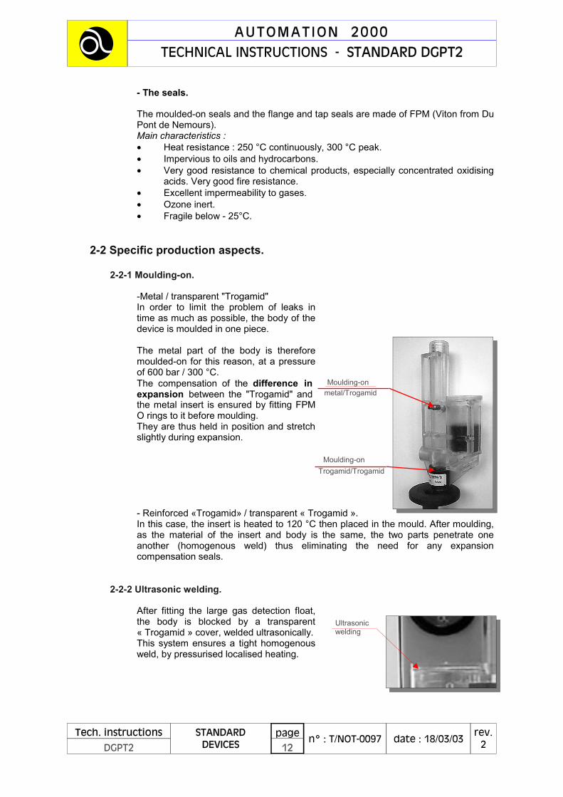
2-2-1 Moulding-on.
-Metal / transparent "Trogamid" In order to limit the problem of leaks in time as much as possible, the body of the device is moulded in one piece. The metal part of the body is therefore moulded-on for this reason, at a pressure of 600 bar / 300 °C. The compensation of the difference in expansion between the "Trogamid" and the metal insert is ensured by fitting FPM O rings to it before moulding. They are thus held in position and stretch slightly during expansion.
- Reinforced «Trogamid» / transparent « Trogamid ». In this case, the insert is heated to 120 °C then placed in the mould. After moulding, as the material of the insert and body is the same, the two parts penetrate one another (homogenous weld) thus eliminating the need for any expansion compensation seals.
2-2-2 Ultrasonic welding.
After fitting the large gas detection float, the body is blocked by a transparent « Trogamid » cover, welded ultrasonically. This system ensures a tight homogenous weld, by pressurised localised heating.
Moulding-on metal/Trogamid
Trogamid/Trogamid Moulding-on
AUTOMATION 2000 TECHNICAL INSTRUCTIONS - STANDARD DGPT2
Tech. instructions
DGPT2 n° : T/NOT-0097
rev. 2 date : 18/03/03
STANDARD DEVICES
page 12
123
Ultrasonic welding

2-3 Standards. 2-3-1 Design standards.
« Low voltage device assemblies - Part 1: Standard assemblies and assemblies derived from standard assemblies ».
• Paragraph 7.1.3.3 « The space available for connection must permit external conductors to be connected correctly and multi-core cables not to be constrained. The conductors must not be subjected to constraints which reduce their nominal working life… » The plate has been designed to provide the maximum amount of space possible to external connections, without constraining the cables. The internal wiring of the device respects the minimum curve radii recommended by this standard.
Paragraph 7.2.2 « In the case of an assembly which is to be installed outdoors and an assembly under a cover for indoor installation in places where there is a high level of humidity, and the temperature varies greatly, suitable measures (ventilation and/or heating indoors, drain holes, etc.) should be taken to prevent condensation which could damage the inside of the assembly. However, the degree of protection specified must also be maintained at the same time. » The housing is equipped with 3 holes at the bottom.
• Paragraph 8.1.2
Individual tests « The individual tests include: A) the inspection of the assembly, including the wiring and an electrical operation test. B) A dielectric test C) A check of the protection measures and the electrical conduction of the protection circuit. These tests can be carried out in any order. Note: the fact that individual tests are carried out in the manufacturer's workshops does not mean that the party installing the device is freed from the obligation of checking it after transport and installation. » The settings of pressure switches and thermostats can be altered to actuate the contacts and then reset precisely by the user, without any special equipment being required.
Conditions of use of liquid dielectrics : first part, fire risks. This standard explain in which case and why the used of a protective system for transformer is obligatory or not. To read this standard, it is necessary to read before the NF C 27-300 standard « Classification of liquid dielectrics according to their fire behavious ».
)x
For details, refer to chapter 5
« Tests and commissioning »
THE NF EN 60439-1 STANDARD
AUTOMATION 2000 TECHNICAL INSTRUCTIONS - STANDARD DGPT2
Tech. instructions
DGPT2 n° : T/NOT-0097
rev. 2 date : 18/03/03
STANDARD DEVICES
page 13
123
THE NF C 17-300
2-3-2 Production standards. This standard concerns the safety of equipment required to obtain the CE brand, but does not concern the DGPT2 directly.
• Paragraph 1.1.3 « …this standard does not apply : - to passive equipment… and devices which operate without any electrical power sources. » Which is our case.
However, if the user of our device wishes to include it in an assembly which may be subject to CE approval, this should be possible. For this reason, we have followed this standard as closely as possible.
• Purpose of this standard
« Dangers. The purpose of applying this standard is to forewarn against accidents or damage arising from the following dangers : - electrical shock → The DGPT is concerned - risks of energy transfer → Not concerned - fire → The DGPT is concerned - mechanical and thermal risks → Not concerned - radiation risks → Not concerned - chemical risks » → Not concerned
• Paragraphs 2.1 to 3.3.9 « Electrical shock. » - the device is equipped with 2 earth connections with conduction of the earth. - labels inside providing all of the information required on operating voltages, degrees of insulation and dielectric rigidity.
• Paragraphs 4.4 to 4.4.5 "Fire" - use of metal for the external covers. The housing of the DGPT2 is made of metal and allows fire to be contained. - All plastics inside the housing are of the "non-fire spreading" or self- extinguishing type (in compliance with the CENELEC HD 21-55 standard).
THE NF EN 60950 STANDARD
AUTOMATION 2000 TECHNICAL INSTRUCTIONS - STANDARD DGPT2
Tech. instructions
DGPT2 n° : T/NOT-0097
rev. 2 date 18/03/03
STANDARD DEVICES
page 14
123
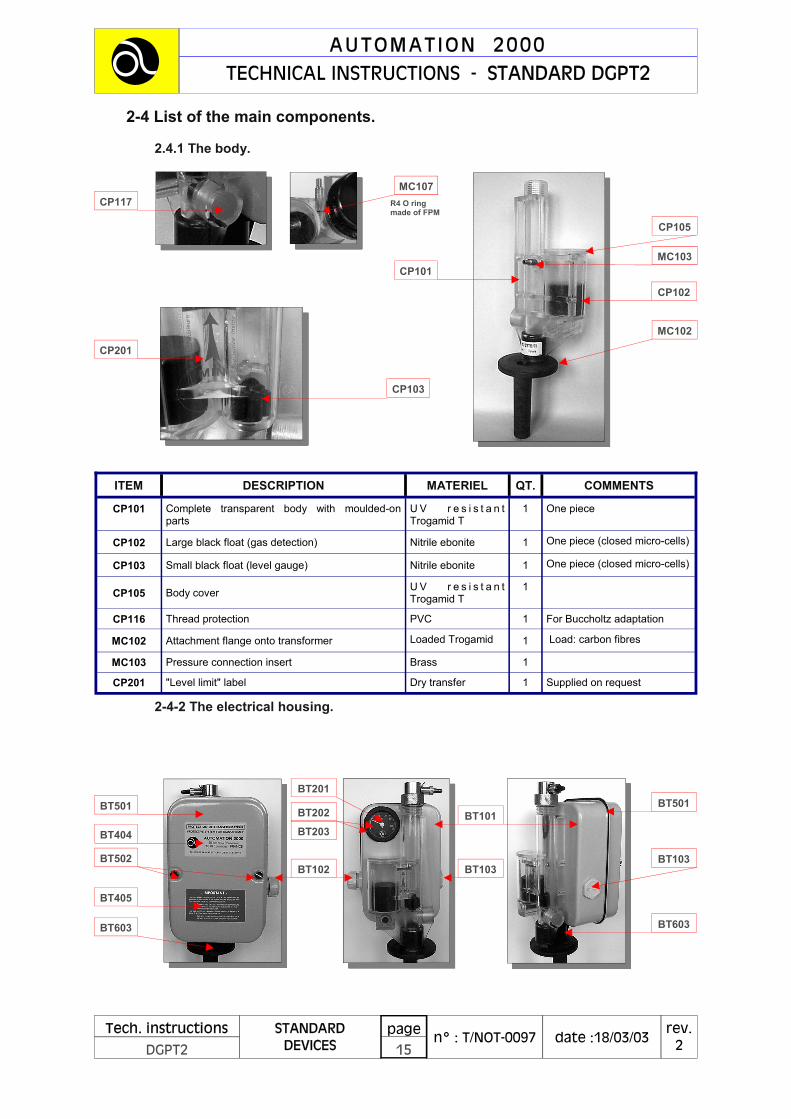
2-4 List of the main components.
2.4.1 The body.
2-4-2 The electrical housing.
CP117
CP201
CP101
CP102
CP103
CP105
MC102
MC103
R4 O ring made of FPM
BT501
BT404
BT103
BT603
BT501 BT101
BT103
BT201
BT203 BT202
BT102 BT502
BT405
BT603
ITEM DESCRIPTION MATERIEL QT. COMMENTS
CP101 Complete transparent body with moulded-on parts
U V r e s i s t a n t Trogamid T
1 One piece
CP102 Large black float (gas detection) Nitrile ebonite 1 One piece (closed micro-cells)
CP103 Small black float (level gauge) Nitrile ebonite 1 One piece (closed micro-cells)
CP105 Body cover U V r e s i s t a n t Trogamid T
1
CP116 Thread protection PVC 1 For Buccholtz adaptation
MC102 Attachment flange onto transformer Loaded Trogamid 1 Load: carbon fibres
MC103 Pressure connection insert Brass 1
CP201 "Level limit" label Dry transfer 1 Supplied on request
AUTOMATION 2000 TECHNICAL INSTRUCTIONS - STANDARD DGPT2
Tech. instructions
DGPT2 n° : T/NOT-0097
rev. 2 date :18/03/03
STANDARD DEVICES
page 15
123
MC107

2-4-3 Electrical component plate.
ITEM DESCRIPTION MATERIAL QT. COMMENTS
BT101 DGPT2 type housing XES 8/10 steel 1 Anti-corrosion treatment. Epoxy paint. Class : IP567
BT102/105 M25 (ISO) stuffing gland with nut Polyamide (PEP) 1 Capacity: 13 to 18 mm
BT103/105 M25 (ISO) closing with nut Polyamide (PEP) 1
BT201 Thermometer 1
57 mm Ø Scale : 30 to 120 °C Accuracy : ±2 % full scale. Temperature compensated
BT202/203 Thermometer support (2 piece) U V r e s i s t a n t T r o g a m i d T Polyamide (PEP)
1 Physical and UV protection
BT404 "Transformer protection" label Polyester 1 French/English bilingual
BT405 "IMPORTANT" label Polyester 1 French/English bilingual
BT501 DGPT2 type housing cover XES 8/10 steel EPDM seal (-40 to +120 °C)
1 Anti-corrosion treatment. Epoxy paint. Class : IP567
BT502 Cover attachment screw Nickel plated brass 2 Copper and nickel plated
BT603 Capillary tube protection Black polyamide 6 1 Capillary protection
PL207
PL201
PL133 PL206
PL136
PL132
PL137
PL407
PL407
PL50 PL138
PL510
PL5
ITEM DESCRIPTION MATERIAL QT. COMMENTS
PL132 Identification and connection plate Matt polyester 1
PL133 Electrical component plate 12/10 steel plate 1 Epoxy paint
PL136 Pressure switch 1
Scale : 0 to 0.5 bar Accuracy : ±2% full scale Accuracy of display : ±0,05b Response time : 5 ms
PL137/138 Industrial terminals with cheek Polyamide (PA) 12, 1 Test points Clamping capacity : 2.5 mm²
PL201 Thermostat label Polyester 1
PL205 T1 and T2 thermostats with bulb and capillary tube
2
Scale : 30 to 120 °C Accuracy of display : ±2.5 °C. Temperature compensated
PL206 T1 thermostat button Polyamide 6, yellow 1 Graduated in steps of 5 °C
PL207 T2 thermostat button Polyamide 6, red 1 Graduated in steps of 5 °C
AUTOMATION 2000 TECHNICAL INSTRUCTIONS - STANDARD DGPT2
Tech. instructions
DGPT2 n° : T/NOT-0097
rev. 2 date : 18/03/03
STANDARD DEVICES
page 16
123

Table continued…
2-4-4 The drain tap. (part n° RP109)
2-4-5 The accessories.
ITEM DESCRIPTION MATERIAL QT. COMMENTS
PL407 Component plate/cover attachment spacer Nickel plated brass 2
PL510 Bulb attachment screw Stainless steel 1 M3.5
PL513 Gas detection magnetic bulb, complete 1 Can easily be replaced by the user.
RP101
RP102
RP105
RP108
RP107
RP103
RP201
ITEM DESCRIPTION MATERIAL QT. COMMENTS
RP101 Tap body Brass 1 Copper + nickel plating
RP102 Tap collar Brass 1 Copper + nickel plating
RP103 Actuating cock Brass 1 Copper + nickel plating
RP105 Translation movement lock screw Stainless steel 1 With thread lock +
RP107 Cock plug PVC 1
RP108 Actuation lock pin Stainless steel 1 Can replace lead sealing
RP201 Tap/body interface seal Viton 1
End sealing. WARNING We strongly recommend that TEFLON is not used to seal the threads , as it prevents the seal being tightened correctly and causes leaks...
ITEM DESCRIPTION MATERIAL QT. COMMENTS
AC101 Body/transformer attachment flange seal (supplied with DGPT2) Viton 1
Flat seal : ext. Ø 78 mm int. Ø 67 mm Thickness: 6 mm
AC102 Flange attachment hooks (supplied with DGPT2)
Steel or 316 stainless steel 4 Bichromated
AC201 Anti-magnetism shielding (supplied on request) XC 1
Anti-corrosion treatment. Epoxy paint.
AUTOMATION 2000 TECHNICAL INSTRUCTIONS - STANDARD DGPT2
Tech. instructions
DGPT2 n° : T/NOT-0097
rev. 2 date : 18/03/03
STANDARD DEVICES
page 17
123
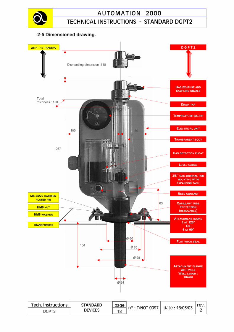
2-5 Dimensioned drawing.
DRAIN TAP
ELECTRICAL UNIT
TRANSPARENT BODY
CAPILLARY TUBE PROTECTION (REMOVABLE)
LEVEL GAUGE
TEMPERATURE GAUGE
GAS DETECTION FLOAT
REED CONTACT
3/8’’ GAS JOURNAL FOR MOUNTING WITH
EXPANSION TANK
GAS EXHAUST AND SAMPLING NOZZLE
TRANSFORMER
M8 25/22 CADMIUM PLATED PIN
ATTACHMENT FLANGE WITH WELL
WELL LENGH : 104MM
FLAT VITON SEAL
HM8 NUT
ATTACHMENT HOOKS 3 AT 120°
OR 4 AT 90°
NM8 WASHER
D G P T 2 WITH THE TRANSFO
63
Ø 60
Ø 85
Ø 98
104
Ø 24
Dismantling dimension :110
267
100 56
Total thichness : 150
AUTOMATION 2000 TECHNICAL INSTRUCTIONS - STANDARD DGPT2
Tech. instructions
DGPT2 n° : T/NOT-0097
rev. 2 date : 18/03/03
STANDARD DEVICES
page 18
123

2-6 The options.
As the DGPT is of an open modular design, there are many options available which allow it to be adapted to the various customer specifications. In particular, the solutions proposed for a safety update of an old transformer are numerous and simple (to avoid emptying the transformer tank). If the options do not satisfy your requirement, or if the device has to be adapted, please feel free to contact us (see page 6 for our address, telephone number, etc.).
List of options.
The following list is not exhaustive.
DGPT2 DESCRIPTION OPTION
} THERMOMETER WITH MAXIMUM NEEDLE AM
WITH THERMOMETER AT
} FOR ASKAREL DIELECTRIC AS
} WITH EXTERNAL METAL CONNECTOR CE
} 4MM2 INDUSTRIAL TERMINALS CQ
} THERMOMETER ON COVER FRONT FACE FA
TRHE TYPE FLANGE HE
} BUCCHOLTZ TYPE MOUNTING ADAPTER IB
} WITH ANCHORING MARINE TYPE STUFFING GLAND PA
FLANGELESS SB
} WITH SAFETY VALVE SO
} PRECISION THERMOMETER ±1°C TS
} LOCKING THERMOSTATS TV
} PRESSURE SWITCH WITH 2 SIMULTANEOUS CONTACTS 2P
} GASEOUS DISCHARGE WITH 2 SIMULTANEOUS CONTACTS 2G
} 2 GAS CONTACTS, 2 PRESSURE CONTACTS, NON-INVERTING 2GPNI
} REMOTE PROBE (PT100) FOR TEMPERATURE RELAY PT
)
For further details on these function, refer to the « GENERAL »
technical instructions n° T/NOT-0096
x
AUTOMATION 2000 TECHNICAL INSTRUCTIONS - STANDARD DGPT2
Tech. instructions
DGPT2 n° : T/NOT-0097
rev. 2 date : 18/03/03
STANDARD DEVICES
page 19
123

)x IF YOUR TRANSFORMER IS STILL UNDER GUARANTEE, CONTACT THE MANUFACTURER BEFORE CARRYING OUT ANY WORK.
THE METHODS DESCRIBED BELOW ARE GIVEN FOR INFORMATION ONLY, AND THE USER IS ENTIRELY RESPONSIBLE FOR CARRYING THEM OUT. THEY ONLY CONCERN THE UPDATING OF THE TRANSFORMER (THE MANUFACTURERS HAVE THEIR OWN FACTORY INSTALLATION PROCEDURES) )x
Remove the drain tap Remove the small float
Black plug
Open/close nozzle
3-1 Preparation.
The two most common cases are : (1) The transformer doesn't have a drain tap. (2) The transformer has a drain tap. Methods will be recommended for these two situations. Preamble : • The power supply to the transformer must be switched off. • The procedure must be carried out when the equipment is not hot (ideal
ambient temperature of 20 °C). • The dielectric level in the transformer should be slightly below the transformer
cover. • The orifice the device is to be mounted on should be open.
3-2 Mounting.
3-2-1) The transformer doesn't have a drain tap.
- Before mounting the device : This allows rapid filling.
3-2-2 With and without drain tap.
• Fit the transformer/protection sealing system : - flat Viton seal supplied with the device. Part n° : AC101
• Mount and attach the device : - either with the metal hooks supplied with the device. Part n°: AC102 (4 off)
3 - MOUNTING THE DEVICE.
AUTOMATION 2000 TECHNICAL INSTRUCTIONS - STANDARD DGPT2
Tech. instructions
DGPT2 n° : T/NOT-0097
rev. 2 date : 18/03/03
STANDARD DEVICES
page 20
123
• Carefully check that the hooks grip correctly and the flat seal is in the correct position.
3-3 Filling.
Before starting, protect the device from any possible accidental spillage of dielectric, especially between the electrical housing and the transparent body.
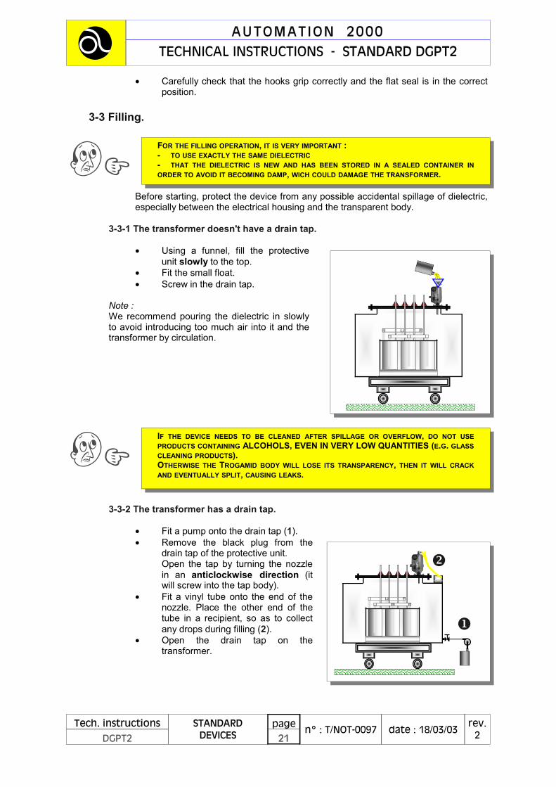
3-3-1 The transformer doesn't have a drain tap.
• Using a funnel, fill the protective unit slowly to the top.
• Fit the small float. • Screw in the drain tap.
Note : We recommend pouring the dielectric in slowly to avoid introducing too much air into it and the transformer by circulation.
3-3-2 The transformer has a drain tap.
• Fit a pump onto the drain tap (1). • Remove the black plug from the
drain tap of the protective unit. Open the tap by turning the nozzle in an anticlockwise direction (it will screw into the tap body).
• Fit a vinyl tube onto the end of the nozzle. Place the other end of the tube in a recipient, so as to collect any drops during filling (2).
• Open the drain tap on the transformer.
(x IF THE DEVICE NEEDS TO BE CLEANED AFTER SPILLAGE OR OVERFLOW, DO NOT USE PRODUCTS CONTAINING ALCOHOLS, EVEN IN VERY LOW QUANTITIES (E.G. GLASS CLEANING PRODUCTS). OTHERWISE THE TROGAMID BODY WILL LOSE ITS TRANSPARENCY, THEN IT WILL CRACK AND EVENTUALLY SPLIT, CAUSING LEAKS.
FOR THE FILLING OPERATION, IT IS VERY IMPORTANT : - TO USE EXACTLY THE SAME DIELECTRIC - THAT THE DIELECTRIC IS NEW AND HAS BEEN STORED IN A SEALED CONTAINER IN ORDER TO AVOID IT BECOMING DAMP, WICH COULD DAMAGE THE TRANSFORMER. (x
AUTOMATION 2000 TECHNICAL INSTRUCTIONS - STANDARD DGPT2
Tech. instructions
DGPT2 n° : T/NOT-0097
rev. 2 date : 18/03/03
STANDARD DEVICES
page 21
123

• Switch on the pump so as to fill the protective unit slowly then the expansion tank.
• As soon as the dielectric starts running out of the nozzle of the drain tap, close it by turning the nozzle in a clockwise direction.
• Stop the pump as soon as the DGPT2 is filled up to its tap. • Close the transformer drain tap. • Remove the pump, tube and recipient. Put the black plug onto the tap nozzle.
)
This method has the
advantage of making very little air penetrate into the dielectric and the transformer
x
AUTOMATION 2000 TECHNICAL INSTRUCTIONS - STANDARD DGPT2
Tech. instructions
DGPT2 n° : T/NOT-0097
rev. 2 date : 18/03/03
STANDARD DEVICES
page 22
123

4 - ELECTRICAL OPERATION.
4-1 Preamble.
The contacts of the various functions of the DGPT2 are of the « changeover » type. They therefore have a « common » point, a « Normally Closed » contact and a « Normally Open » contact. They therefore provide the user with the possibility of choosing between « absent » or « emission » operation.
- Absent operation (still called « negative safety ») In this case, the normally closed NC contact of the changeover should be used. It will open when the fault occurs. - Emission operation (still called « positive safety ») In this case, the normally open NO contact of the changeover should be used. It will close when the fault occurs. In the device, the output from this contact is always cabled with the blue (common) and white (NC) wires.
4-2 Operating diagrams.
4-2-1 Discharge of gases.
• The volume of gas which actuates the contact is determined by its construction. By analogy with the Buccholtz (110 cm3), the volume varies between 90 and 130 cm3, depending on the type of dielectric used : dielectric density < 1 = volume < 110 cm3 dielectric density > 1 = volume > 110 cm3
• in the case of gases being discharged, the gas takes the place of the dielectric in the DGPT tank, causing the level to drop.
COMMON
NC contact (Normally Closed
NO Contact (Normally Open)
IN THE FOLLOWING DIAGRAMS, THE CONTACTS ARE SHOWN NOT POWERED AND AT REST, WHICH IS TO SAY NOT UNDER THE INFLUENCE OF THE FAULT SHOWN. )x
AUTOMATION 2000 TECHNICAL INSTRUCTIONS - STANDARD DGPT2
Tech. instructions
DGPT2 n° : T/NOT-0097
rev. 2 date : 18/03/03
STANDARD DEVICES
page 23
123

• when the float is between 3 and 5mm above the bottom of the tank, the magnet moves the reed contact from NC to NO by magnetism (open between 1 and 2, closed between 2 and 3). Remark : It should be noted that this is not a permanent contact. If the level rises in the tank (after bleeding for example), the reed contact will return to its initial position.
4-2-2 Tank pressure.
• Excess tank pressure may be due to : - the transformer being overfilled, - the dielectric expanding too much, - a clear short circuit, and the electrical arc formed causes an instantaneous shock wave.
• excess pressure is detected by a direct action bellows pressure switch. It is linked to the pressure in the transformer tank by means of a capillary tube welded into the pressure insert (MC103).
• the tank excess pressure set point is not defined by Automation 2000 but by the transformer manufacturer. A "customer" technical specification provides this value.
• when a transformer is updated by adding a DGPT2 to it, it is supplied with a standard setting of 0.2 bar, unless requested otherwise.
• Reminder of the characteristics of the pressure switch : - very short response time : 5 milliseconds - linear system - fidelity and repeatability - due to its linearity and accuracy, the set point can be set or reset by the user without any special tools being required. - the setting system can be lead sealed. - display accuracy : ± 0.05 bar - accuracy : ± 2 % of the full scale (0.01 bar) - scale : 0 - 0.5 bar
Float with magnet
Reed
Gas accumulation tank
NORMAL LEVEL
NC NO
C
3 2 1
Reed change-over contact
DGPT2 terminal block
IN ALL CASES, WE RECOMMEND THAT YOU CONTACT THE MANUFACTURER OF THE TRANSFORMER FOR THE EXACT VALUE OF THE EXCESS PRESSURE SET POINT (DEPENDENT ON THE ELASTICITY OF THE TANK). )x
AUTOMATION 2000 TECHNICAL INSTRUCTIONS - STANDARD DGPT2
Tech. instructions
DGPT2 n° : T/NOT-0097
rev. 2 date : 18/03/03
STANDARD DEVICES
page 24
123

• When the tank pressure reaches the reference value displayed (± 0.01 bar), the pressure switch contact moves from the NC to the NO position (open between 4 and 5, closed between 5 and 6). Remark : This is not a permanent contact. When the excess pressure disappears (after bleeding or when the dielectric cools down for example), the contact returns to its initial position.
4-2-3 Dielectric temperature.
• The increase in temperature may be due to : - an electrical fault causing localised heating. - intensive use of the transformer (above the service conditions recommen ded by the manufacturer).
• The temperature is monitored by 2 independent bulb/capillary and liquid expansion type thermostats, with temperature compensation.
• The bulbs are housed in the well of the attachment flange, which is permanently immersed in the dielectric.
• The temperature set points are not defined by Automation 2000 but by the transformer manufacturer. A customer technical specification defines these values.
• When the transformer is updated by adding a DGPT2, it is supplied with the following standard settings : 90 °C for T1 100 °C for T2
IN ALL CASES, WE RECOMMEND THAT YOU CONTACT THE MANUFACTURER OF THE TRANSFORMER FOR THE EXACT VALUE OF THE TEMPERATURE SET POINT. )x
PRESSURE SWITCH
Bellows
Setting system
NORMAL PRESSURE
NC NO
C
6 5 4
Pressure switch change-over contact
DGPT2 terminal block
AUTOMATION 2000 TECHNICAL INSTRUCTIONS - STANDARD DGPT2
Tech. instructions
DGPT2 n° : T/NOT-0097
rev. 2 date : 18/03/03
STANDARD DEVICES
page 25
123

• When the dielectric temperature reaches the set point displayed (± 2.5°C), the T1 thermostat contact moves from the NC to the NO position (open between 7 and 8, closed between 8 and 9).
• When the dielectric temperature reaches the set point displayed (± 2.5 °C), the T2 thermostat contact moves from the NC to the NO position (open between 10 and 11, closed between 11 and 12).
Remark: This is not a permanent contact for T1 or T2. When the excess temperature disappears (when the dielectric cools down for example), the contact returns to its initial position.
)
For further details on this equipment, refer to the « GENERAL » technical
instructions n° T/NOT-0096 para. 1.3
x
AUTOMATION 2000 TECHNICAL INSTRUCTIONS - STANDARD DGPT2
Tech. instructions
DGPT2 n° : T/NOT-0097
rev. 2 date : 18/03/03
STANDARD DEVICES
page 26
123
T2 setting button
T1 setting button
NORMAL TEMPERATURES T2 AND T1
DGPT2 terminal block
T2 change-over contact
T1 change-over contact
NC NO
C
12 11 10
NC NO
C
9 8 7

4-3 Connection diagram.
4-4 Sectioning capacity.
IN THIS DIAGRAM, THE CONTACTS ARE SHOWN NOT POWERED AND AT REST, WHICH IS TO SAY NOT UNDER THE INFLUENCE OF THE FAULT SHOWN. )x
DGPT2 internal
switches
Terminal 12 11 10
NO NC
C
9 8 7
NO NC
C
6 5 4
NO NC
C
3 2 1
NO NC
C
T2 thermostat
contact
T1 thermostat
contact
Pressure switch contact
Gas reed
contact
GAS PRESSURE T1 TEMP. T2 TEMP.
TO APPL ICAT ION
CURRENT (ON RESISTIVE LOAD) ALTERNATING DIRECT
250V- 50HZ MAX. 110V 48V 24V
DISCHARGE OF GASES 3A 2A 2A 2A
EXCESS PRESSURE 5A 2A 3A 5A
TEMPERATURES 5A 2A 3A 5A
FUNCTIONS
AUTOMATION 2000 TECHNICAL INSTRUCTIONS - STANDARD DGPT2
Tech. instructions
DGPT2 n° : T/NOT-0097
rev. 2 date : 18/03/03
STANDARD DEVICES
page 27
123

4-5 Attributions of contacts.
This paragraph can also be found in the "GENERAL" tech. instructions n° T/NOT-0096 Our device provides you with non-polarised dry electrical contacts, whose function is attributed by yourself to protect and monitor your transformer, in compliance with the standards and decrees in force.
However… we can provide, simple logical advice as to the possible attribution of the functions. 4-5-1 Discharge of gases.
In general, this is a slow phenomenon. An alarm would therefore appear to be sufficient in order to check the transformer on site (if possible) and carry out work if required. In the case of a very violent discharge, the excess tank pressure will act before it. However, the NFC 13-100 and NFC 13-200 standards provide for it as a trigger, referring to the "Buccholtz", which has no excess tank pressure contacts. (Furthermore, these standards refer to transformers with expansion tanks and completely filled transformers).
4-5-2 Excess tank pressure.
A very large and rapid phenomenon, it may be advisable to use it as a trigger. Which triggers ? As this phenomenon generally occurs in the case of serious damage, it would seem logical to isolate the transformer so that the fault is no longer powered. Which level ? • The standard recommends that a transformer should not be cut off when
under load, so therefore the secondary then the primary should be cut off (NFC 13-100 and NFC 13-200).
• If either (or both) of the circuits is not equipped with controlled isolating devices, the user must use the equipment as best as possible, or make the required modifications to the automated system.
• In all cases, a high sectioning capacity fast-blow fuse is obligatory (NFC 13-200, section 551).
• In the case of automatic cut off of the secondary winding and on a back-up system, it must be ensured that the secondary winding of the transformer cannot be powered again by a transformer in parallel.
WARNING ! AS WE HAVE NO INFORMATION ON THE ENVIRONMENT BEFORE OR AFTER THE TRANSFORMER, IT IS IMPOSSIBLE FOR US TO DEFINE A STANDARD USE FOR THE 3 DGPT FUNCTIONS PREVIOUSLY DESCRIBED, EITHER AS AN ALARM OR TO TRIGGER. (x
AUTOMATION 2000 TECHNICAL INSTRUCTIONS - STANDARD DGPT2
Tech. instructions
DGPT2 n° : T/NOT-0097
rev. 2 date : 18/03/03
STANDARD DEVICES
page 28
123

4-5-3 Temperatures.
T1: the first temperature threshold can be used as an alarm in order to warn the user that the transformer is operating close to its nominal power rating (guarantee level). T2: the second threshold has to protect the transformer against use beyond the maximum temperature defined by the manufacturer. In general, it will be used as a trigger on the consumption side (there is no thing to prevent it being used to cut off the primary winding supply as well).
REMINDER : THE SOLUTIONS CHOSEN AND ADOPTED BY THE CUSTOMER OR ITS SUB-CONTRACTOR COMMITS THEIR RESPONSABILITY. UNDER NO CIRCUMSTANCES CAN AUTOMATION 2000 BE HELD RESPONSIBLE IN THE CASE OF PROBLEMS, BEYOND THE DEVICE’S DRY CONTACT OUTLET TERMINALS.
(x
AUTOMATION 2000 TECHNICAL INSTRUCTIONS - STANDARD DGPT2
Tech. instructions
DGPT2 n° : T/NOT-0097
rev. 2 date : 18/03/03
STANDARD DEVICES
page 29
123

Tech. instructions
DGPT2 n° : T/NOT-0097
rev. 2 date : 18/03/03
STANDARD DEVICES
page 30
5 - TESTS.
BEFORE CARRYING OUT THE TESTS : • Ensure that the power supply to the transformer is switched off. • Check the cabling carefully. • Check that the servo units are powered so that the loops can be tested up to the final
element (LED, etc. for alarm function, and the various actuators for trigger function).
5-1 Discharge of gases.
Element concerned : reed contact PL513 Moving a magnet under the reed housing will change the position of the changeover contact. Check that the loop is operating correctly.
5-2 Excess tank pressure.
Element concerned : pressure switch PL136 Using a spanner, turn the setting knob in the direction shown by the arrow to bring the reference value to zero. The changeover contact changes position. After checking that the servo loop is operating correctly, reset the set point to the value marked on the identification and connection plate PL132. Warning : this test is completely impossible to do with the PM1 or PM2 options.
5-3 T1 temperature.
Element concerned : thermostat PL205 Turn the setting knob PL206 to below the 30 °C graduation. The changeover contact changes position. After checking that the servo loop is operating correctly, reset the set point to the value marked on the identification and connection plate PL132.
5-4 T2 temperature.
Element concerned : thermostat PL205 Same comments as for « T1 temperature ».
)x AS RECOMMENDED BY THE STANDARD, FUNCTIONAL AND ELECTRICAL TESTS MUST BE CARRIED OUT BEFORE FINAL COMMISSIONING. (REFER TO CHAPTER 2-3 « STANDARDS » OF THIS DOCUMENT).
Reed housing
Magnet
Setting knob
Identification plate
Set point
Setting knob
Identification plate
Set point
AUTOMATION 2000 TECHNICAL INSTRUCTIONS - STANDARD DGPT2 123

6 - TROUBLESHOOTING.
6-1 Problem area : discharge of gases.
6-1-1 Question n° 1.
Every time the transformer is switched on, the "gas discharge" contact moves to the fault position then returns to its normal position. In addition, no gas is observed in the body of the device (the large float is at the top of its tank). On certain transformers, the magnetic losses when switching on (especially under no or little load) can be sufficient to actuate the reed of the DGPT2. In general, this change of position does not last longer than 10 ms, which is to say the time of one half cycle in 50 Hz, which often makes the problem difficult to pinpoint. The solution consists of : - fitting anti-magnetism shielding (item AC201. see page 17, sub paragraph 2-4-5, "accessories"). Fitting it does not require any modification to the DGPT2 or special tooling and it is totally effective. To fit it, refer to the technical instructions T/NOT-0085 appended to this document.
6-1-2 Question n° 2.
When testing the DGPT2 and the associated servo systems, the "gas discharge" contact switches to its fault position and stays there. No gas is observed in the body of the device (the large float is at the top of its tank). Following this anomaly, the actuation of the contact is tested again using a magnet, as described on page 26 (paragraph 5-1 "Discharge of gases"). It is observed that the contact does not change position any more and remains closed in the fault position. When testing, voltage or current surges can occur, most often caused by defective equipment, or cabling or relay errors. Long cables can also caused current surges if switching takes place. Routing low voltage servo cables with power cables (motor power supply, transformer power, etc.) often leads to significant interference by electrical and electromagnetic induction. These different phenomena lead to the contacts of the reed sticking or being welded.
( ?
)x ANSWER...
( ?
)x ANSWER...
BEFORE CARRYING OUT ANY WORK ON YOUR TRANSFORMER : CONTACT THE MANUFACTURER - BY OBLIGATION IF IT IS STILL UNDER GUARANTEE - BY PRUDENCE IF IT IS NO LONGER UNDER GARANTEE. (x
AUTOMATION 2000 TECHNICAL INSTRUCTIONS - STANDARD DGPT2
Tech. instructions
DGPT2 n° : T/NOT-0097
rev. 2 date : 18/03/03
STANDARD DEVICES
page 31
123

The solution consists of : - firstly checking the cabling, the servo systems associated to the DGPT2 and the cable routing if necessary. - if the contact is simply stuck together, simply testing the reed with a magnet will free them. - if the contact is welded, the PL513 reed contact must be changed. The reed can be changed quickly and easily by the user. (Refer to the technical instructions n° T/NOT-0085). To change the reed : - Contact us so that we an send you a new reed. The fitting instructions are enclosed with it.
6-1-3 Question n° 3.
The gas discharge contact shows a fault. The presence of gas in the tank can be observed in the body of the DGPT2 (the large float is at the bottom of its tank). The device has operated correctly...! Now it is just a question of determining whether the gas is caused by decomposition or simply air. The solution consists of : - informing the transformer manufacturer. - depending on the reply received, take a sample of the gas and have it analy sed. - send the manufacturer the results and follow the manufacturer's advice. If it is just air, and you are authorised to do so, you can bleed the device and thus cause the level in the body to rise again. If the level does not rise (cold ambient temperature and low transformer load), the level can be raised without adding dielectric by creating a slight negative pressure inside the DGPT2 using a bicycle pump with an inverted membrane. This type of pump can be bought directly from Automation 2000 upon request. Moving the tap. The DGPT2 tap can be used to bleed it and take samples.
1 - Remove the black plug and the lock pin (see parts list). 2 - On the threaded journal of the cock, mount your sampling system if required. 3 - Open the tap by turning the cock in an anti-clockwise direction. 4 - The cock must be screwed into the body of the tap. Sample as required then close the tap by turning the cock in a clockwise direction. Wipe, fit the pin and screw on the black plug.
( ?
)x ANSWER...
AUTOMATION 2000 TECHNICAL INSTRUCTIONS - STANDARD DGPT2
Tech. instructions
DGPT2 n° : T/NOT-0097
rev. 2 date : 18/03/03
STANDARD DEVICES
page 32
123
1 2 3
6-2 Problem area : excessive tank pressure.
6-2-1 Question n° 4.
The excess tank pressure contact shows a fault. The phenomenon occurs frequently, as soon as the transformer reaches its operating temperature. The contact returns to normal when the transformer cools down. There may be 2 causes to this problem : 1 - The transformer the device is mounted on has a rigid tank and is not suitable for complete filling. The expansion of the dielectric therefore causes excessive pressure in the tank. It is essential that the transformer is not used in these conditions. The transformer needs to be modified in order to be used. Solution : Contact the transformer manufacturer and read the "General" technical instructions n° T-NOT-0088 carefully. 2 - Dielectric has been added when not required, in incorrect conditions. The expansion of the dielectric therefore causes excessive pressure in the tank. Solution : Contact the transformer manufacturer.
6-3 Miscellaneous.
6-3-1 Question n° 5.
The body of the device has become matt or opaque in certain areas. In addition, fine cracks can be seen on the surface of the Trogamid. No deposits of products which could damage the transparency of the body are observe. Is the device UV resistant…? As explained in paragraph 2-1-2 "Main materials", Trogamid T is impervious to UV light. However, it is rapidly degraded by alcohols. Even an atmosphere heavy with alcohol vapours will create a similar result. First of all, the surface attacked becomes opaque, then fine cracks appear which in turn lead to increasingly deeper splits and finally by the rupture of the material. Dielectric leaks then occur. Note : the symptoms described of matt or opaque appearance do not occur every time and depend above all on the type of alcohol used. (For example, isopropyl alcohol only causes cracks and splits). (Refer to page 9, paragraph 2-1-2 "Main materials", "Transparent body"). Solution : Unfortunately, the only solution is to change the device, if the damage is already done. If this is caused by a deposit, when cleaning, ensure that the product used is completely free from any type of alcohol whatsoever.
( ?
)x ANSWER...
( ?
)x ANSWER...
AUTOMATION 2000 TECHNICAL INSTRUCTIONS - STANDARD DGPT2
Tech. instructions
DGPT2 n° : T/NOT-0097
rev. 2 date : 18/03/03
STANDARD DEVICES
page 33
123

7 - MAINTENANCE.
7-1 The transparent body.
In very polluted or intensive agricultural atmospheres, successive layers of deposits can make the body of the device less transparent. If this is the case, clean it carefully with a product which is totally free from any alcohol whatsoever (refer to 6-3-1 Question n° 5, answer).
7-2 The level of dielectric in the body.
The level can fluctuate according to the ambient temperature and the operating temperature of the transformer. The fluctuations are of low amplitude and there is no need to add dielectric as soon as the level drops. However, if the level drops far enough to cause a "gas discharge" fault, inform the transformer manufacturer (refer to 6-1-3 Question n° 3, answer).
7-3 Annual check.
If your automated systems and safety devices need to be checked once a year, we inform you that there is no problem in testing the DGPT2 contacts and the set points, which can easily be reset by the user (refer to chapter 5 - TESTS).
8 - GUARANTEE AND AFTER-SALES SERVICE.
8-1 Guarantee.
This equipment has a three year parts and labour guarantee, parts must be delivered to our workshops.
8-2 After-Sales Service.
No work is carried out by Automation 2000 on transformers on site. A telephone help line is at your service from 8 a.m. to 6 p.m. for all technical or sales enquiries.
USUALLY THE DGPT2 DOES NOT REQUIRE ANY SPECIAL MAINTENANCE. )x
AUTOMATION 2000 TECHNICAL INSTRUCTIONS - STANDARD DGPT2
Tech. instructions
DGPT2 n° : T/NOT-0097
rev. 2 date : 18/03/03
STANDARD DEVICES
page 34
123

—– MEMO —–
AUTOMATION 2000 TECHNICAL INSTRUCTIONS - STANDARD DGPT2
Tech. instructions
DGPT2 n° : T/NOT-0097
rev. 2 date : 18/03/03
STANDARD DEVICES
page 35
123

9 - APPENDIX.
T/NOT-0085 Changing the REED contact. T/NOT-0100 Fitting the anti-magnetism shielding.
AUTOMATION 2000 TECHNICAL INSTRUCTIONS - STANDARD DGPT2
Tech. instructions
DGPT2 n° : T/NOT-0097
rev. 2 date 18/03/03
STANDARD DEVICES
page 36
123

—– MEMO —–
AUTOMATION 2000 TECHNICAL INSTRUCTIONS - STANDARD DGPT2
Tech. instructions
DGPT2 n° : T/NOT-0097
rev. 2 date : 18/03/03
STANDARD DEVICES
page 37
123

CHANGING THE REED CONTACT (DECEMBER 1996 MODEL)
Before carrying out any work in the electrical unit of the DGP or the DGPT2, ensure that the power supply to the contacts of the device has been switched off. Any work carried out when the device is powered could cause an electrical shock
If the cause of the destruction of the Reed has not been determined : firstly, carefully check the circuit to which the bulb is connected to avoid the new Reed
PROCEDURE
Fit the new reed in the housing and push it right in..
4
Fit the lock-screw and tighten until the reed is held securely in its housing and does not move.
5
Wire the reed as follows : red wire : terminal 1 blue wire : terminal 2 white wire : terminal 3
6
The operation of the reed is checked by moving a magnet underneath the reed housing (approximately where the lock-screw is situated). If switching does not occur, check that the reed is fitted in the correct position (pushed at the bottom of its
Put the wires inside the housing and fit the cover.
After removing the cover : disconnect the reed wires
REED
1
Remove the reed by pulling it towards you from the inside of the housing
3
Using a Phillips screwdriver, loosen off the lock-screw until the reed holder tube is
2
SCREW
Caution !
Warning !
AUTOMATION 2000 20, rue de la Pommeraie 78310 COIGNIERES (FRANCE) (33) 01-34-61-42-32 (33) 01-34-61-89-19
Tech.instructions
REPAIR n° : T/NOT-0085
rev. 2 date : 04/08/99
DGPT2 all types DGP all types
page 1
123


What is the role of the anti-magnetisme shielding ?
FITTING THE ANTI-MAGNETISM SHIELDING
PROCEDURE
It is possible that when powered up, in exceptional cases, with the transformer under load or not, that an alarm or unexpected triggering occurs due to the gas discharge reed.
This temporary phenomenon (flicker of the reed) is caused by the magnetic field
emitted by the transformer. it can be easily eliminated by fitting anti-magnetism shielding (see photo
opposite) to the protection unit. This operation does not require any modifications to be made to the device or
special toolig. The anti-magnetism shielding is available on request from Automation 2000.
Unscrew the 2 nuts on the earth screw of the housing by approximately 5mm.
Position the shielding : - slot 1 should be aligned with the earth screw
(3) - slot 2 should be aligned with the rib on the
Insert the shielding as shown. Ensure that the top of the shielding touches the top of the cylindrical body.
Finish by tightening the 2 nuts on the earth screw.
3 4
1 2
AUTOMATION 2000 20, rue de la Pommeraie 78310 COIGNIERES (FRANCE) (33) 01-34-61-42-32 (33) 01-34-61-89-19
Tech.instructions
REPAIR n° : T/NOT-0100
rev. 1 date : 06/08/99
DGPT2 all types DGP all types
page 1
123


BEFORE CARRYING OUT THE TESTS :
• Ensure that the power supply to the transformer is switched off. • Check the cabling carefully. • Check that the servo units are powered so that the loops can be tested up to the final
element (LED, etc. for alarm function, and the various actuators for trigger function).
5-1 Discharge of gases.
Element concerned : reed contact PL513 Moving a magnet under the reed housing will change the position of the changeover contact. Check that the loop is operating correctly.
5-2 Excess tank pressure.
Element concerned : pressure switch PL136 Using a spanner, turn the setting knob in the direction shown by the arrow to bring the reference value to zero. The changeover contact changes position. After checking that the servo loop is operating correctly, reset the set point to the value marked on the identification and connection plate PL132. Warning : this test is completely impossible to do with the PM1 or PM2 options.
5-3 T1 temperature.
Element concerned : thermostat PL205 Turn the setting knob PL206 to below the 30 °C graduation. The changeover contact changes position. After checking that the servo loop is operating correctly, reset the set point to the value marked on the identification and connection plate PL132.
5-4 T2 temperature.
Element concerned : thermostat PL205 Same comments as for « T1 temperature ».
)x AS RECOMMENDED BY THE STANDARD, FUNCTIONAL AND ELECTRICAL TESTS MUST BE CARRIED OUT BEFORE FINAL COMMISSIONING. (REFER TO CHAPTER 2-3 « STANDARDS » OF THIS DOCUMENT).
Setting knob
Identification plate
Set point
Setting knob
Identification plate
Set point
Reed housing
Magnet
AUTOMATION 2000 TECHNICAL INSTRUCTIONS - STANDARD DGPT2 123
TESTS ON THE SPOT
WARNING… WHEN YOU MAKE TESTS BY SHUNTING THE TERMINALS, YOU ARE TESTING THE CABLE AND NOT THE DGPT2… !