Date: 12th April 2018 TENDER FOR DRILLING OF BORE … · The contractor’s hydro-geologist should...
16
Date: 12 th April 2018 TENDER FOR DRILLING OF BORE HOLE & CONSTRUCTION OF WATER TOWER IN GBARNGA, BONG COUNTY Mary’s Meals International is a UK based humanitarian organization which responds worldwide in school feeding. We are feeding over 1.2 million children globally in their places of education. We have a Country Programme in Liberia with a school feeding program reaching around 114,292 students in 507 schools in Bomi, Cape Mount, Bong and Montserado Counties. Mary’s Meals Liberia is seeking for contractors to undertake construction works in its warehouse base in Gbarnga, in Bong County in Liberia. Contractors are instructed to prepare and submit well costed BoQ’s for the project they are capable of undertaking in the schedule below. Submissions should be sent to the emails below or dropped in the tender box at Marys Meals address in Tubmanburg. Requirements for submission The tender should be accompanied by: 1. Annex 1 contains specifications and scope works for the various projects and must be read carefully 2. Up to date GOL Business Registration Certificate. 3. Valid LRA tax and other relevant statutory tax clearance certificates. 4. Organisation profile (including supplier name, physical address, contact person telephone, mobile, email, TIN number etc.) 5. Annex 2 cover page MUST be completed and returned with all the documents Site visit and viewing will be on 17 th and 18 th from 1 pm to 4 pm both days Please send your proposals to the emails below on or before the 24 th of April 2018. [email protected] [email protected]
Transcript of Date: 12th April 2018 TENDER FOR DRILLING OF BORE … · The contractor’s hydro-geologist should...

Date: 12
th April 2018
TENDER FOR DRILLING OF BORE HOLE & CONSTRUCTION OF WATER TOWER
IN GBARNGA, BONG COUNTY
Mary’s Meals International is a UK based humanitarian organization which responds worldwide
in school feeding. We are feeding over 1.2 million children globally in their places of education.
We have a Country Programme in Liberia with a school feeding program reaching around
114,292 students in 507 schools in Bomi, Cape Mount, Bong and Montserado Counties.
Mary’s Meals Liberia is seeking for contractors to undertake construction works in its warehouse base in
Gbarnga, in Bong County in Liberia.
Contractors are instructed to prepare and submit well costed BoQ’s for the project they are capable of
undertaking in the schedule below.
Submissions should be sent to the emails below or dropped in the tender box at Marys Meals address in
Tubmanburg.
Requirements for submission
The tender should be accompanied by:
1. Annex 1 contains specifications and scope works for the various projects and must be read
carefully
2. Up to date GOL Business Registration Certificate.
3. Valid LRA tax and other relevant statutory tax clearance certificates.
4. Organisation profile (including supplier name, physical address, contact person telephone,
mobile, email, TIN number etc.)
5. Annex 2 cover page MUST be completed and returned with all the documents
Site visit and viewing will be on 17th
and 18th
from 1 pm to 4 pm both days
Please send your proposals to the emails below on or before the 24th
of April 2018.

ANNEX 1
CONSTRUCTION OF BOREHOLE AND WATER TOWER
Mary’s Meals Liberia Borehole construction document
1.0 Scope of works
The scope of the works require that contractor furnish successful borehole to the client. A successful
borehole is defined as one conforming to all the requirements for the siting, drilling, pumping testing, yield
and water quality requirements. The well delivers more than 450l/hr and passes the minimum acceptable
potable water quality standards (Government of Liberia acceptable water quality standards). By this
definition, the bidder MUST include costs of replacement of unsuccessful borehole (poor water quality and
dry boreholes) in their BoQ.
The well successfully drilled and tested will be installed with a submersible pump with stainless steel (G316
steel) pipes and rods or depending on the depth of the well, PPR pipes and stainless steel rods. As a general
rule, all boreholes with submersible pump deeper than 39 meters will be installed with Stainless steel pipes
and rods (G316 steel) as described in the specification.
All wells with submersible pump shallower than 39m will be installed with PPR pipes and stainless steel
rods. The contractor is required to price these separate items in the BoQs.
The depths of installation of submersible pump must be approved by Mary’s Meals Liberia.
The successful contractor will carry out the siting/hydrogeological survey for the borehole location, carrying out the
drilling work, pumping test, water quality tests and the installation of the pump ready for use.
1.1 Location of the works
The work is in Mary’s Meals Warehouse compound in Gbanga, Bong County.
1.2 Borehole siting
The contractor is to carry out detailed geophysical analysis in the WAREHOUSE compound in Mary’s Meals
compound in Gbanga. A method of geophysical survey best suited to the geography/geology of the area is to be
employed
The geophysical analysis will include the desk study, the hydro census and the geophysical survey. The reports of
the surveys will be included as part of the final reports submitted for the whole works.
The contractor’s hydro-geologist should carry out a hydro census in the vicinity of the target area. This will include a
detailed inventory of all existing water supplies to ensure that the current site does not influence nearby wells and to
be able to make decisions that could affect the success of the new boreholes.

The contractor should ensure that the siting/Geophysics work is to be carried out by suitably qualified and
experienced person(s). The nominated person(s) shall be available for the specified contract period. Proposed
changes to the hydro-geologist should be agreed with the supervising engineer/Mary’s Meals Liberia.
During the siting, the hydro-geologist should ensure that representatives of Mary’s Meals shall be involved. Mary’s
Meals will assist with compound accessibility.
2.0 Drilling site
Borehole locations shall be identified in agreement with Mary’s Meals responsible and consultation with the office.
Sites selected for the borehole should preferably be within the WAREHOUSE compound. Borehole should not be
sited in or near to places that get flooded during rains. Flood plains should be avoided. Additional measures should
be taken to ensure that site is located outside the minimum distance prescribed from sanitation installations, sources
of pollution, landfills etc
It is advisable that the hydrologist uses their experience to determine alternative suitable sites for borehole
construction so that these can be developed if initial site is abandoned for any reasons including dry well or
unsuitable water quality well.
The contractor shall drill the borehole at location as determined by their hydrogeological survey. Access to the site
shall be the responsibility of the Contractor. Tracks required for access of drilling plant, gear, camp and accessories
to the well site shall be made by the contractor, and shall minimize as much as possible interference with existing
fences.
3.0 Environmental protection of the site
Care must be taken in the handling and storage of drilling fluids, oils, greases and fuel to avoid introducing
environmental contaminants and pollutants. The Contractor shall dispose of any toxic materials including drilling
fluids, cuttings and discharged waters in a manner approved by the Client and so as not to contaminate/pollute the
property. The contractor shall adhere to relevant National regulations and guidelines on Environmental protection that
apply to drilling. The Contractor shall ensure that all their personnel are aware of Environmental protection
requirements.
4.0 Materials for the works and Workmanship
Materials that will form part of the complete works must be supplied new and never used. Materials must comply with
the minimum specifications in the relevant codes. Materials not specified here must comply with the minimum
specifications in the relevant codes of practice. Where a national standard does not exist for the material, the relevant
International Standard shall apply.

The Contractor is expected to carry out all works as specified and in a professional manner. The Contractor shall
carry out operations in accordance with the terms of the contract and to the satisfaction of the Client. The Contractor
shall use suitable equipment, and supply efficient and experienced staff.
a) The Contractor will provide an experienced project Coordinator to oversee the drilling and testing to be carried out
under this Contract.
b) The Contractor will maintain a full crew on the drilling unit and pump test unit. If a member of crew quits for
personal reasons or must leave because of illness or injury, the Contractor will replace him as soon as possible with a
worker of similar experience.
c) If the Client is dissatisfied with the performance of members of the crew, such members shall be informed of their
shortcomings and warned by the contractor. If no change results within a reasonable period, the Contractor will be
notified and requested to take necessary measures on the unsatisfactory crewmember.
5.0 Contractor to provide all equipment for the works
All necessary machinery, equipment and materials to carry out the drilling, test pumping, headwork construction shall
be provided by the contractor. Test pumping equipment shall be independent from the drilling rig(s). Prior to
mobilization the Client shall verify the specifications and state of repair of all major items of plant and transport, and
shall have the right to order the removal and/or replacement of any items which in his opinion are insufficient or in
unsatisfactory condition. Acceptance by the Client of the Contractor’s proposed plant and transport does not relieve
the contractor of his obligations under this contract, in cases where such plant and transport accepted by the Client
fails to successfully complete the required works.
6.0 Drilling method
The Contractor should make exclusive use of direct or reverse circulation rotary and down-the-hole hammer drilling
techniques, using an appropriate (biodegradable) drilling fluid. Bentonite is not to be used as a drilling fluid.
The Contractor may use any motorized drilling technique that will achieve the depth and diameter required of the well,
provided that the techniques used are those specified in his proposal and approved by the Client. The rig to be
deployed must be capable of drilling to at least a depth of 25% beyond the anticipated final depth at the required
diameter. Temporary or complete PVC casing may be installed in the borehole to prevent formation heave or
collapse.
The average anticipated borehole depth will be in the region 30m. Shallower or deeper boreholes may be
encountered.
7.0 Strata sampling and borehole geo data
At completion of drilling, the contractor will be required to complete the borehole geo-log with all information
describing the properties of the samples, appearances of water and aquifers, rock types and sampling details.

The contractor will then complete the borehole log reports forms and supply them together with the borehole
completion records including water quality test certificates to the client. Incomplete records or un-obtained samples
are a reasonable ground for rejection of a borehole
The contractor will be required to hand to the client at the end of the drilling operation borehole logs and
pumping test data.
8.0 Borehole depth and diameter
The Contractor shall drill to the total appropriate depth depending on the geological formation and to a diameter that
shall allow minimum borehole nominal diameter bore of 4 inches (103mm) at the completion of the borehole,
including casing installation. Expected borehole depths are an average 30 meters depth. The contractor will be
required to drill a minimum of 30m deep.
The minimum acceptable stable yield at test pumping shall be 450 ltrs/hr.
Drilling diameter should be a minimum of 6.5” (165mm) through unconsolidated formations such as sands, gravels,
clays and silts using mud rotary methods (or similar approved methods)
Drilling diameter should be a minimum of 5.875” (150mm) through consolidated rock utilizing down-the-hole hammer
and compressed air supply – augmented as required by water foam injection
The Contractor shall however drill to the total depth and at such diameter as will be instructed by the Supervising
Engineer. No borehole will be accepted if drilled to such depth and diameter other than agreed by the Supervising
Engineer.
In collapsing formations, the borehole drilling will be telescopic. In this case 200mm (8 inch) or of appropriate
diameter drilling (approved by the Engineer) is required to allow installation of temporary casing. This temporary
casing must enable further drilling of 200mm (8 inch) boreholes for the installation of 100mm (4 inch) nominal internal
diameter PVC casing and screen.
9.0. Verticality and Alignment
The well shall be vertical, shall be drilled and cased straight, and all casings/screens shall be set round, plumb and
true to line. If required by the Client, the Contractor shall make a verticality test during and after drilling by approved
methods and at his own expense to demonstrate that the departure from the vertical does not exceed 0.1% between
ground level and the bottom of the well.
If this departure is exceeded, the Contractor shall make the necessary corrections to the approval of the Client,
without additional payment. If the error cannot be corrected, then drilling shall cease, and a new well shall be drilled.
The abandoned well shall be backfilled and /or capped. No payment shall be made for re-drilling, the
sealing/backfilling of the abandoned well, or for moving to a new site. Any materials (i.e. casing, screens, gravel pack,
cement, etc) lost in the abandoned well shall be at the contractor’s cost.
10. Loss of equipment
Any equipment lost down a well must be removed by the Contractor or the well shall be considered a lost bore. A
replacement well shall have to be constructed at the Contractor’s expense. The contractor shall not be entitled to
further payments for such a well.
11. Water supply for drilling
The contractor shall make his own arrangement for obtaining, transporting and pumping of water required for drilling
purposes and for use by the drilling crew at WAREHOUSE compound.
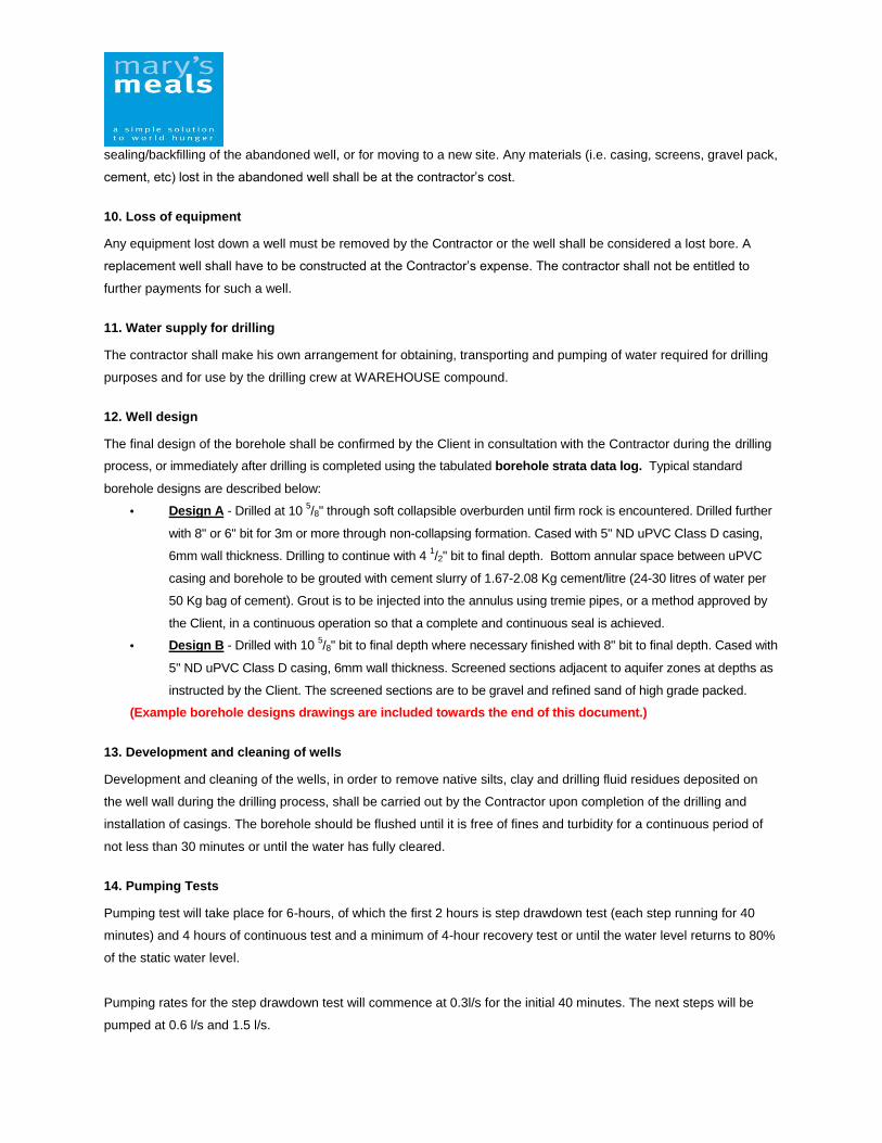
12. Well design
The final design of the borehole shall be confirmed by the Client in consultation with the Contractor during the drilling
process, or immediately after drilling is completed using the tabulated borehole strata data log. Typical standard
borehole designs are described below:
• Design A - Drilled at 10 5/8" through soft collapsible overburden until firm rock is encountered. Drilled further
with 8" or 6" bit for 3m or more through non-collapsing formation. Cased with 5" ND uPVC Class D casing,
6mm wall thickness. Drilling to continue with 4 1/2" bit to final depth. Bottom annular space between uPVC
casing and borehole to be grouted with cement slurry of 1.67-2.08 Kg cement/litre (24-30 litres of water per
50 Kg bag of cement). Grout is to be injected into the annulus using tremie pipes, or a method approved by
the Client, in a continuous operation so that a complete and continuous seal is achieved.
• Design B - Drilled with 10 5/8" bit to final depth where necessary finished with 8" bit to final depth. Cased with
5" ND uPVC Class D casing, 6mm wall thickness. Screened sections adjacent to aquifer zones at depths as
instructed by the Client. The screened sections are to be gravel and refined sand of high grade packed.
(Example borehole designs drawings are included towards the end of this document.)
13. Development and cleaning of wells
Development and cleaning of the wells, in order to remove native silts, clay and drilling fluid residues deposited on
the well wall during the drilling process, shall be carried out by the Contractor upon completion of the drilling and
installation of casings. The borehole should be flushed until it is free of fines and turbidity for a continuous period of
not less than 30 minutes or until the water has fully cleared.
14. Pumping Tests
Pumping test will take place for 6-hours, of which the first 2 hours is step drawdown test (each step running for 40
minutes) and 4 hours of continuous test and a minimum of 4-hour recovery test or until the water level returns to 80%
of the static water level.
Pumping rates for the step drawdown test will commence at 0.3l/s for the initial 40 minutes. The next steps will be
pumped at 0.6 l/s and 1.5 l/s.

Constant rate pumping test pumping rates will normally range between 0.5l/s and 2.5l/s but may not fall below
450l/hr. If the pumping rate is below 450l/hr then the borehole will be regarded as dry.
Once the flow rate has been determined and preliminary adjustments made, the measured discharge rate shall be
maintained within 15% of the required rate for the duration of the test. Persistent fluctuations beyond this tolerance
will require abortion of the test.
Failure of the operation to produce the desired minimum pumping rate for a period greater than one percent of the
elapsed pumping time shall also require abortion of the test.
Any test, which is aborted due to the reasons above, shall be repeated after recovery of the water level. The
contractor will not claim stand by time for aborted tests or for standing time during water level recovery after aborted
tests.
15. Capping of well
During well construction, installation, development and test pumping, the Contractor shall use all reasonable
measures to prevent entrance of foreign materials into the well. Well caps should be used at all times. Wooden logs
shall not be used to replace well caps. The Contractor shall be responsible for any objectionable materials that may
fall into the well and any effect it may have on water quality or quantity until completion of the Works and acceptance
by the Client.
16. Acceptance of well
The Client shall accept the well upon satisfactory completion of all drilling operations, installation of casings
and screens, development works, pumping tests, presentation and approval of complete drilling reports and
logs and provided the well yield is above minimum recommended values and water quality tests are suitable
for potable water according to the GOL standards. In addition, the contractor will provide a complete detail of
lifespan of the well.
17. Typical Schematic Drawing of Well Designs and Water tower
Borehole design 1: Unconsolidated formations


Borehole design 2: consolidated formations

Borehole design 3: Consolidated formation
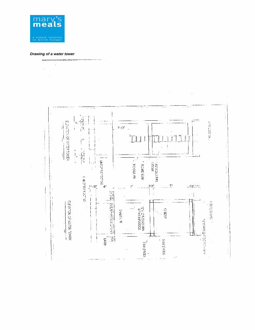
Drawing of a water tower


Annex 1 Bore Hole Completion Record (Typical)
Bore Hole No……………………………………………………. Bore Hole Name…………………………………………………. _______________________________________________________________________
1. Location………………… Area ……………………. County………………………. Coordinates; N ………………E………………… Elevation …………………. ASL 3. Contactor/Driller………………………………………… Address……………………. ………………………………………………………………………………………… 4. Type of Bore Hole; Drilled; Driven; Bored; Jetted; Other……………………………… ………………………………………………………………………………………….. Type & Make of the drilling Rig………………………………………………………... 5. Bore Hole Design & Construction (Sketch to accompany) Drilling Started………………………… Drilling Completed…………………………. All work completed……………………………………………………………………… Total Depth: Reported………m; Measured…….m; Final (Backfilled) Depth;…..m Hole Diameter………………mm. From ……….m to……………….m ……………….mm From ……….m to……………….m ……………….mm From ……….m to……………….m ……………….mm From ……….m to……………….m Permanent Casing: Plain: Type………..; Dia……..mm; Length………m; From………m to……….m Type………..; Dia……..mm; Length………m; From………m to……….m Type………..; Dia……..mm; Length………m; From………m to……….m Type………..; Dia……..mm; Length………m; From………m to……….m Screen: Type & Make……………………………………………………………………………… Diameter………mm; Length……….m Set from…….m to……………m Gravel Pack: Size of grains…………mm, Roundness (Good, Fair, Poor)……………………….. Volume inserted to the annular space………cu.m, from………….m to…………..m 6. Aquifer: 1st Water Struck at ……………….m.; Water rest level………………………….m Main Aquifer struck at …………...m. ; Water rest level…………………………m Water bearing material…………………………, from……..m to………………..m Other Aquifers, Remark etc……………………………………………………………………... ……………………………………………………………………………………………………. ……………………………………………………………………………………………… 7. Yield: SWL………m.; DWL……….m. below GL; Discharge………………….Ltrs/min after pumping ……………..Hrs; Recovered to SWL in …………….Minutes; Recommended production discharge………….Ltrs/Hr, with pump set at …………..m below GL

8. Bore Hole Development Start……………. Finish …………… Hrs………………… 9. Pumping Test Record in summary (Attach detailed test records – Test pumping & BH recovery tests) – All depth measurements to be in Metres below GL
Description
Date of Test (Day, Month, Year)
Depth of BH at time of test (m)
Static Water Level (SWL) before test (m)
Type of Pump used
Depth of Pump Intake (m)
Discharge (Ltrs/Minute)
Dynamic/Pumping water level (m)
After Pumping continuously for (Hrs)
Time of recovery to original SWL (Minutes)
Rate of Recovery – WL after 5 Minutes (m)
WL after 20 Minutes (m)
WL after 60 Minutes (m)
WL after 180 Minutes (m)
WL after 360 Minutes (m)
Additional pumping tests to be mentioned in Remarks 10. Quality of Water: (Water Quality Test Certificates to accompany) Sample (Yes/No) collected at …………………………. Hour on …………………….. (Date) Sediment………………………….., Taste ……………………….., Odour……………………. Colour………………………………; Specific conductivity……………….μmho/cu. m; Temperature……...
oC
11. Remarks: (Drilling difficulties, gravel pack details, all pertinent information about drilling and completion of the Bore Hole) …………………………………………………………………………………………………………………………………………………………………………………………………………………………………………………………………………………………………………………………………………………………………………………………………………………………………………………………………………………………………………………………………………………………………………………………………………………………………………………………………………….
12. Sketch of Bore Hole Construction (Sketch to include depth, & changes of hole diameter; casing positions, manner of casings (if different diameters), connections, and casing connection to the screen; depths of screen, how casing is closed at the bottom, formation caving zones and any other pertinent information)

Annex 2 – Cover Page
Contractor Form - Complete and submit with your Bid
Supplier
name:
Contact
person:
Office
address:
Telephone
number:
address:
Supplier declaration: Tick box (√) to
indicate
agreement:
I certify that I am the official representative of the company
named above.
I have given Mary's Meals International Liberia a copy of our
company's updated GOL Business Registration Certificate).
I have given Mary's Meals International Liberia a copy of our
company's valid LRA tax and other relevant statutory tax
clearance certificates
I have given Mary's Meals International Liberia a copy of our
company's/organisation profile (including supplier name,
physical address, contact person telephone, mobile, email,
TIN number etc.
Name Signature Date

Company Stamp