
DATA SHEET SKY73063-11: 1700 – 2100 MHz High Linearity
12
Skyworks Solutions, Inc. • Phone [781] 376-3000 • Fax [781] 376-3100 • [email protected] • www.skyworksinc.com 201017D • Skyworks Proprietary Information • Products and Product Information are Subject to Change Without Notice • July 6, 2011 1 DATA SHEET SKY73063-11: 1700 – 2100 MHz High Linearity, Single Up/Downconversion Mixer Applications • 2G/3G base station transceivers: − GSM/EDGE, CDMA, UMTS/WCDMA • Wi-Fi (802.11) • WiMAX (802.16) • 3GPP Long-Term Evolution • Wireless Local Loop • High performance radio links • Land mobile radio • Private mobile radio Features • Operating frequency range: 1700 to 2100 MHz • IF frequency range: 100 to 200 MHz • Insertion loss: 6.5 dB • Input IP3: +28 dBm • Noise Figure: 8.6 dB • Integrated LO driver • Integrated low loss RF balun • On-chip SPDT LO switch • Small, MCM (20-pin, 5 x 5 mm) package (MSL3, 260 °C per JEDEC J-STD-020) Figure 1. SKY73063-11 Block Diagram Description The SKY73063-11 is a fully integrated up/downconversion mixer that includes a Local Oscillator (LO) driver, an LO switch, and a high linearity mixer. A low loss RF balun has also been included to reduce design complications and lower system cost. The SKY73063-11 features an input IP3 of +28 dBm and an insertion loss of 6.5 dB, making the device an ideal solution for high dynamic range systems such as 2G/3G base station receivers. The LO switch provides good isolation between LO inputs and supports the switching time required for GSM/EDGE base stations. The SKY73063-11 is manufactured using a robust silicon BiCMOS process and has been designed for optimum long-term reliability. The SKY73063-11 single up/downconversion mixer is provided in a compact, 20-pin 5 x 5 mm Multi-Chip Module (MCM). A functional block diagram is shown in Figure 1. The pin configuration and package are shown in Figure 2. Signal pin assignments and functional pin descriptions are provided in Table 1.
Transcript of DATA SHEET SKY73063-11: 1700 – 2100 MHz High Linearity

Skyworks Solutions, Inc. • Phone [781] 376-3000 • Fax [781] 376-3100 • [email protected] • www.skyworksinc.com 201017D • Skyworks Proprietary Information • Products and Product Information are Subject to Change Without Notice • July 6, 2011 1
DATA SHEET
SKY73063-11: 1700 – 2100 MHz High Linearity, Single Up/Downconversion Mixer Applications
• 2G/3G base station transceivers: − GSM/EDGE, CDMA, UMTS/WCDMA
• Wi-Fi (802.11)
• WiMAX (802.16)
• 3GPP Long-Term Evolution
• Wireless Local Loop
• High performance radio links
• Land mobile radio
• Private mobile radio
Features
• Operating frequency range: 1700 to 2100 MHz
• IF frequency range: 100 to 200 MHz
• Insertion loss: 6.5 dB
• Input IP3: +28 dBm
• Noise Figure: 8.6 dB
• Integrated LO driver
• Integrated low loss RF balun
• On-chip SPDT LO switch
• Small, MCM (20-pin, 5 x 5 mm) package (MSL3, 260 °C per JEDEC J-STD-020)
Figure 1. SKY73063-11 Block Diagram
Description The SKY73063-11 is a fully integrated up/downconversion mixer that includes a Local Oscillator (LO) driver, an LO switch, and a high linearity mixer. A low loss RF balun has also been included to reduce design complications and lower system cost.
The SKY73063-11 features an input IP3 of +28 dBm and an insertion loss of 6.5 dB, making the device an ideal solution for high dynamic range systems such as 2G/3G base station receivers. The LO switch provides good isolation between LO inputs and supports the switching time required for GSM/EDGE base stations.
The SKY73063-11 is manufactured using a robust silicon BiCMOS process and has been designed for optimum long-term reliability. The SKY73063-11 single up/downconversion mixer is provided in a compact, 20-pin 5 x 5 mm Multi-Chip Module (MCM). A functional block diagram is shown in Figure 1. The pin configuration and package are shown in Figure 2. Signal pin assignments and functional pin descriptions are provided in Table 1.
DATA SHEET • SKY73063-11 UP/DOWNCONVERSION MIXER
Skyworks Solutions, Inc. • Phone [781] 376-3000 • Fax [781] 376-3100 • [email protected] • www.skyworksinc.com 2 July 6, 2011 • Skyworks Proprietary Information • Products and Product Information are Subject to Change Without Notice • 201017D
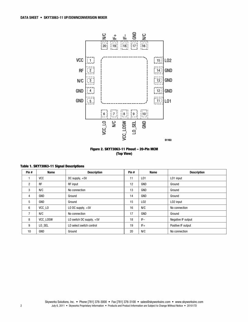
Figure 2. SKY73063-11 Pinout – 20-Pin MCM (Top View)
Table 1. SKY73063-11 Signal Descriptions
Pin # Name Description Pin # Name Description
1 VCC DC supply, +5V 11 LO1 LO1 input
2 RF RF input 12 GND Ground
3 N/C No connection 13 GND Ground
4 GND Ground 14 GND Ground
5 GND Ground 15 LO2 LO2 input
6 VCC_LO LO DC supply, +5V 16 N/C No connection
7 N/C No connection 17 GND Ground
8 VCC_LOSW LO switch DC supply, +5V 18 IF– Negative IF output
9 LO_SEL LO select switch control 19 IF+ Positive IF output
10 GND Ground 20 N/C No connection

DATA SHEET • SKY73063-11 UP/DOWNCONVERSION MIXER
Skyworks Solutions, Inc. • Phone [781] 376-3000 • Fax [781] 376-3100 • [email protected] • www.skyworksinc.com 201017D • Skyworks Proprietary Information • Products and Product Information are Subject to Change Without Notice • July 6, 2011 3
Functional Description The SKY73063-11 is a high linearity, single up/downconversion mixer, optimized for base station receiver applications. The device consists of a low loss RF balun and high linearity passive mixer.
An LO amplifier is also included that allow the SKY73063-11 to connect directly to the output of a Voltage Controlled Oscillator (VCO). This eliminates the extra gain stages needed by most discrete passive mixers. A Single Pole, Double Throw (SPDT) switch has been included to select between two different LO inputs (LO1 and LO2) for frequency hopping applications such as GSM.
RF Balun and Passive Mixer
The RF balun provides a single ended input, which can easily be matched to 50 Ω using a simple external matching circuit. The balun offers very low loss, and excellent amplitude and phase balance.
The high linearity SKY73063-11 is a passive, double-balanced mixer that provides a very low conversion loss, and excellent 3rd Order Input Insertion Point (IIP3).
Additionally, the balanced nature of the mixer provides for high port-to-port isolation.
LO Buffer and SPDT LO Switch
The LO buffer allows the input power of the SKY73063-11 to be in the range of ±6 dBm. The LO section is optimized for high-side LO injection. However, each of the two LOs can be driven over a wide frequency range with some degradation in performance.
A high isolation SPDT switch allows the SKY73063-11 to be used for frequency hopping applications. This switch provides greater than 40 dB of LO1 to LO2 isolation:
LO_SEL Input LO Path Selected
High LO1 (pin 11) enabled
Low LO2 (pin 15) enabled
For applications that do not require frequency hopping, LO_SEL is fixed to one state and the appropriate LO input is used. An internal pull-down resistor enables the LO2 input.
Electrical and Mechanical Specifications The absolute maximum ratings of the SKY73063-11 are provided in Table 2 and the recommended operating conditions in Table 3. Electrical characteristics for the SKY73063-11 are provided in Table 4.
Typical performance characteristics of the SKY73063-11 are illustrated in Figures 3 through 14.
Table 2. SKY73063-11 Absolute Maximum Ratings
Parameter Symbol Minimum Maximum Units
Supply voltage, +5 V VCC 4.5 5.5 V
Supply current ICC 100 mA
RF input power PRF +20 dBm
IF input power PIF +20 dBm
LO input power PLO +20 dBm
Operating case temperature TC –40 +85 °C
Junction temperature TJ +150 °C
Storage case temperature TSTG –40 +150 °C
Notes: Exposure to maximum rating conditions for extended periods may reduce device reliability. There is no damage to device with only one parameter set at the limit and all other parameters set at or below their nominal value. Exceeding any of the limits listed here may result in permanent damage to the device.
CAUTION: Although this device is designed to be as robust as possible, Electrostatic Discharge (ESD) can damage this device. This device must be protected at all times from ESD. Static charges may easily produce potentials of several kilovolts on the human body or equipment, which can discharge without detection. Industry-standard ESD precautions should be used at all times.

DATA SHEET • SKY73063-11 UP/DOWNCONVERSION MIXER
Skyworks Solutions, Inc. • Phone [781] 376-3000 • Fax [781] 376-3100 • [email protected] • www.skyworksinc.com 4 July 6, 2011 • Skyworks Proprietary Information • Products and Product Information are Subject to Change Without Notice • 201017D
Table 3. SKY73063-11 Recommended Operating Conditions
Parameter Symbol Minimum Typical Maximum Units
Supply voltage, +5 V VCC 4.75 5.00 5.25 V
Supply current ICC 83 mA
LO input power PLO –6 0 +6 dBm
LO select input: high low
LO_SELH LO_SELL
2.2
0.8
V V
Operating case temperature TC –40 +85 °C
RF frequency range FRF 1700 2100 MHz
LO frequency range (Note 1) FLO 1800 2300 MHz
IF frequency range FIF 100 200 MHz
Note 1: The SKY73063-11 has been optimized for high-side LO injection. However, the LO can be used outside of the specified frequency range with degraded performance.
Table 4. SKY73063-11 Electrical Specifications (Note 1) (Voltage Supply = +5 V, TC = +25 °C, LO = 0 dBm, RF Frequency = 1875 MHz, IF Frequency = 150 MHz, LO Frequency = 2025 MHz, Unless Otherwise Noted)
Parameter Symbol Test Condition Min Typical Max Units
Downconversion insertion loss ILDOWN RF input to IF output, FRF = 1875 MHz, PRF = –7 dBm
6.5 7.5 dB
Upconversion insertion loss ILUP IF input to RF output, FIF = 150 MHz, PIF = –7 dBm
5.8 7.0 dB
Noise Figure NF 8.6 11.5 dB
Downconversion 3rd Order Input Intercept Point
IIP3DOWN RF input, IRF = 1875 MHz and 1875.8 MHz, PRF = 0 dBm
+24 +28 dBm
Input 1 dB compression point IP1dB Downconversion +15.5 +18.8 dBm
2RF – 2LO 2x2 PRF = 0 dBm
Downconversion Upconversion
–54 –87
–48 –79
dBc dBc
3RF – 3LO 3x3 PRF = 0 dBm
Downconversion Upconversion
–67 –102
–48 –95
dBc dBc
LO1-to-LO2 isolation 32 35 dB
LO leakage: @ RF port @ IF port
–24 –36
–15 –28
dBm dBm
RF to IF isolation Downconversion 41 45 dB
LO_SEL input –20 +150 +250 µA
LO switching time 0.5 µs
RF port return loss ZRF With external matching components
14 dB
LO port return loss ZLO With external matching components
14 dB
IF port return loss ZIF With external matching components
14 dB
Note 1: Performance is guaranteed only under the conditions listed in this Table.
DATA SHEET • SKY73063-11 UP/DOWNCONVERSION MIXER
Skyworks Solutions, Inc. • Phone [781] 376-3000 • Fax [781] 376-3100 • [email protected] • www.skyworksinc.com 201017D • Skyworks Proprietary Information • Products and Product Information are Subject to Change Without Notice • July 6, 2011 5
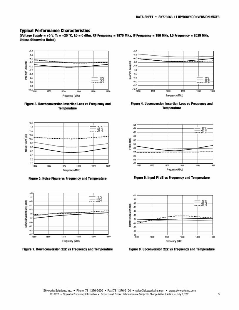
Typical Performance Characteristics (Voltage Supply = +5 V, TC = +25 °C, LO = 0 dBm, RF Frequency = 1875 MHz, IF Frequency = 150 MHz, LO Frequency = 2025 MHz, Unless Otherwise Noted)
Figure 3. Downconversion Insertion Loss vs Frequency and Temperature
Figure 5. Noise Figure vs Frequency and Temperature
Figure 7. Downconversion 2x2 vs Frequency and Temperature
Figure 4. Upconversion Insertion Loss vs Frequency and Temperature
Figure 6. Input P1dB vs Frequency and Temperature
Figure 8. Upconversion 2x2 vs Frequency and Temperature

DATA SHEET • SKY73063-11 UP/DOWNCONVERSION MIXER
Skyworks Solutions, Inc. • Phone [781] 376-3000 • Fax [781] 376-3100 • [email protected] • www.skyworksinc.com 6 July 6, 2011 • Skyworks Proprietary Information • Products and Product Information are Subject to Change Without Notice • 201017D
Figure 9. Downconversion 3x3 vs Frequency and Temperature
Figure 11. LO-to-LO Isolation vs Frequency and Temperature
Figure 13. LO-to-IF Leakage vs Frequency and Temperature
Figure 10. Upconversion 3x3 vs Frequency and Temperature
Figure 12. LO-to-RF Leakage vs Frequency and Temperature
Figure 14. RF-to-IF Isolation vs Frequency and Temperature

DATA SHEET • SKY73063-11 UP/DOWNCONVERSION MIXER
Skyworks Solutions, Inc. • Phone [781] 376-3000 • Fax [781] 376-3100 • [email protected] • www.skyworksinc.com 201017D • Skyworks Proprietary Information • Products and Product Information are Subject to Change Without Notice • July 6, 2011 7
Evaluation Board Description The SKY73063-11 Evaluation Board is used to test the performance of the SKY73063-11 downconversion mixer. An assembly drawing for the Evaluation Board is shown in Figure 15 and the layer detail is provided in Figure 16.
Circuit Design Configurations
The following design considerations are general in nature and must be followed regardless of final use or configuration:
1. Paths to ground should be made as short and as low impedance as possible.
2. The ground pad of the SKY73063-11 provides critical electrical and thermal functionality. The connection to the ground pad should be designed to provide the best ground for the mixer. For more information on soldering the SKY73063-11, refer to the Package and Handling Information section of this Data Sheet.
3. Skyworks recommends including external bypass capacitors on the VCC voltage inputs of the device.
A schematic diagram for the SKY73063-11 Evaluation Board is shown in Figure 17.
Figure 15. SKY73063-11 Evaluation Board Assembly Diagram

DATA SHEET • SKY73063-11 UP/DOWNCONVERSION MIXER
Skyworks Solutions, Inc. • Phone [781] 376-3000 • Fax [781] 376-3100 • [email protected] • www.skyworksinc.com 8 July 6, 2011 • Skyworks Proprietary Information • Products and Product Information are Subject to Change Without Notice • 201017D
Figure 16. SKY73063-11 Evaluation Board Layer Detail

DATA SHEET • SKY73063-11 UP/DOWNCONVERSION MIXER
Skyworks Solutions, Inc. • Phone [781] 376-3000 • Fax [781] 376-3100 • [email protected] • www.skyworksinc.com 201017D • Skyworks Proprietary Information • Products and Product Information are Subject to Change Without Notice • July 6, 2011 9
Figure 17. SKY73063-11 Evaluation Board Schematic

DATA SHEET • SKY73063-11 UP/DOWNCONVERSION MIXER
Skyworks Solutions, Inc. • Phone [781] 376-3000 • Fax [781] 376-3100 • [email protected] • www.skyworksinc.com 10 July 6, 2011 • Skyworks Proprietary Information • Products and Product Information are Subject to Change Without Notice • 201017D
Package Dimensions Figure 18 shows the package dimensions for the 20-pin MCM, and Figure 19 provides the tape and reel dimensions.
Package and Handling Information Since the device package is sensitive to moisture absorption, it is baked and vacuum packed before shipping. Instructions on the shipping container label regarding exposure to moisture after the container seal is broken must be followed. Otherwise, problems related to moisture absorption may occur when the part is subjected to high temperature during solder assembly.
THE SKY73063-11 is rated to Moisture Sensitivity Level 3 (MSL3) at 260 °C. It can be used for lead or lead-free soldering. For additional information, refer to the Skyworks Application Note, PCB Design & SMT Assembly/Rework Guidelines for MCM-L Packages, document number 101752.
Care must be taken when attaching this product, whether it is done manually or in a production solder reflow environment. Production quantities of this product are shipped in a standard tape and reel format.
Figure 18. SKY73063-11 20-Pin MCM Package Dimensions

DATA SHEET • SKY73063-11 UP/DOWNCONVERSION MIXER
Skyworks Solutions, Inc. • Phone [781] 376-3000 • Fax [781] 376-3100 • [email protected] • www.skyworksinc.com 201017D • Skyworks Proprietary Information • Products and Product Information are Subject to Change Without Notice • July 6, 2011 11
Figure 19. SKY73063-11 Tape and Reel Dimensions

DATA SHEET • SKY73063-11 UP/DOWNCONVERSION MIXER
Skyworks Solutions, Inc. • Phone [781] 376-3000 • Fax [781] 376-3100 • [email protected] • www.skyworksinc.com 12 July 6, 2011 • Skyworks Proprietary Information • Products and Product Information are Subject to Change Without Notice • 201017D
Ordering Information Model Name Manufacturing Part Number Evaluation Board Part Number
SKY73063-11 1700-2100 MHz Up/Downconversion Mixer SKY73063-11 TW18-480
Copyright © 2009, 2010, 2011 Skyworks Solutions, Inc. All Rights Reserved.
Information in this document is provided in connection with Skyworks Solutions, Inc. (“Skyworks”) products or services. These materials, including the information contained herein, are provided by Skyworks as a service to its customers and may be used for informational purposes only by the customer. Skyworks assumes no responsibility for errors or omissions in these materials or the information contained herein. Skyworks may change its documentation, products, services, specifications or product descriptions at any time, without notice. Skyworks makes no commitment to update the materials or information and shall have no responsibility whatsoever for conflicts, incompatibilities, or other difficulties arising from any future changes.
No license, whether express, implied, by estoppel or otherwise, is granted to any intellectual property rights by this document. Skyworks assumes no liability for any materials, products or information provided hereunder, including the sale, distribution, reproduction or use of Skyworks products, information or materials, except as may be provided in Skyworks Terms and Conditions of Sale.
THE MATERIALS, PRODUCTS AND INFORMATION ARE PROVIDED “AS IS” WITHOUT WARRANTY OF ANY KIND, WHETHER EXPRESS, IMPLIED, STATUTORY, OR OTHERWISE, INCLUDING FITNESS FOR A PARTICULAR PURPOSE OR USE, MERCHANTABILITY, PERFORMANCE, QUALITY OR NON-INFRINGEMENT OF ANY INTELLECTUAL PROPERTY RIGHT; ALL SUCH WARRANTIES ARE HEREBY EXPRESSLY DISCLAIMED. SKYWORKS DOES NOT WARRANT THE ACCURACY OR COMPLETENESS OF THE INFORMATION, TEXT, GRAPHICS OR OTHER ITEMS CONTAINED WITHIN THESE MATERIALS. SKYWORKS SHALL NOT BE LIABLE FOR ANY DAMAGES, INCLUDING BUT NOT LIMITED TO ANY SPECIAL, INDIRECT, INCIDENTAL, STATUTORY, OR CONSEQUENTIAL DAMAGES, INCLUDING WITHOUT LIMITATION, LOST REVENUES OR LOST PROFITS THAT MAY RESULT FROM THE USE OF THE MATERIALS OR INFORMATION, WHETHER OR NOT THE RECIPIENT OF MATERIALS HAS BEEN ADVISED OF THE POSSIBILITY OF SUCH DAMAGE.
Skyworks products are not intended for use in medical, lifesaving or life-sustaining applications, or other equipment in which the failure of the Skyworks products could lead to personal injury, death, physical or environmental damage. Skyworks customers using or selling Skyworks products for use in such applications do so at their own risk and agree to fully indemnify Skyworks for any damages resulting from such improper use or sale.
Customers are responsible for their products and applications using Skyworks products, which may deviate from published specifications as a result of design defects, errors, or operation of products outside of published parameters or design specifications. Customers should include design and operating safeguards to minimize these and other risks. Skyworks assumes no liability for applications assistance, customer product design, or damage to any equipment resulting from the use of Skyworks products outside of stated published specifications or parameters.
Skyworks, the Skyworks symbol, and “Breakthrough Simplicity” are trademarks or registered trademarks of Skyworks Solutions, Inc., in the United States and other countries. Third-party brands and names are for identification purposes only, and are the property of their respective owners. Additional information, including relevant terms and conditions, posted at www.skyworksinc.com, are incorporated by reference.


![glbeylhj LH - c-o-k.ru · Mkljhckl\h j_]mebjh\Zgby DigiPro ... 1350 1000 1350 1000 1350 1000 1350 1000 1350 1000 H[ .\ha^ .V O [f 3 /q] 2100 1700 2000 1600 1800 1450 1700 1350 2100](https://static.fdocuments.net/doc/165x107/5b3dc0587f8b9a213f8e1028/glbeylhj-lh-c-o-kru-mkljhcklh-jmebjhzgby-digipro-1350-1000-1350-1000.jpg)
