Application of Aerospace Durability and Damage Tolerance ...

Scientific Journal of Impact Factor (SJIF) : 3.134
International Journal of Advance Engineering and Research Development
Volume 1,Issue 11, November -2014
@IJAERD-2014, All rights Reserved 160
ISSN (Print): 2348-6406
ISSN (Online): 2348-4470
DAMAGE TOLERANCE EVALUATION OF A PANEL WITH WINDOW
CUTOUT AND FRAMES IN THE FUSELAGE OF A TRANSPORT AIRFRAME
Amaljith H1, Subin P George
2, Girish K.E
3
1Department of Mechanical Engineering, AJCE, [email protected]
2Department of Mechanical Engineering , AJCE, [email protected]
3Bangalore aircraft industries limited, Bangalore, [email protected]
Abstract— An Aircraft is a very complex mechanical structure having very high structural safety. Due to static
overloading the aircrafts are seldom fail in its service life. As the continuous operation of an aircraft fatigue cracks are
initiate and propagate due to the fluctuating service loads acted in an aircraft structure. Fatigue and damag e tolerance
design and analysis plays an important role in ensuring the airworthiness of an aircraft during its service life. This study
deals with the damage tolerance evaluation of the stiffened panel consisting of a large cutout for passenger window and
bulkheads on either side of the cutout. The passenger window cutout region in the fuselage is a critical location from the
fatigue crack initiation point of view. The maximum tensile stress location will be identified in the panel. The linear stati c
stress analysis is carried out by using MSC NASTRAN and PATRAN Software. Fatigue is a phenomenon in which the
load carrying ability of structures decreases when subjected to fluctuating loads. The fatigue reveals itself in the form of
cracks which propagate. The cracks initiated in the critical location could lead to the catastrophic failure of the aircra ft
if unnoticed. A crack is initiated in the maximum stress region from the analytical model of stiffened panel. The panel is
analysed for different crack length by increasing the crack length in the direction perpendicular to the loading direction.
Stress intensity factor is calculated for different crack length. The ability of the bulk heads in arresting the crack on both
sides of the window cutout region is calculated analytically by comparing the stress intensity factor values with the
fracture toughness of the material. The residual strength is calculated for skin and bulkhead to demonstrate the
bulkheads crack arrest capability and plot the graphs.
Keywords- Aircraft, Fuselage, Window cutout, stress analysis, Damage tolerance, Fatigue, Stress intensity factor, FEM.
I. INTRODUCTION
The structure of an aircraft is a highly complex one, which main ly consists of wings, fuselage and tail. The aircraft
fuselage main ly composed of stressed skins, longitudinal stringers and frames. The structural efficiency of an aircraft
results in light weight and high operating stresses. As an efficient structure aircraft must have three attributes primarily,
one is its ability to perform the intended function, second adequate service life and third the capability of being produced
at reasonable cost. The fuselage of an aircraft is the part that holds crew, passengers and cargo. Aircraft fuselage structure
has to withstand many types of loads and stresses and at the same time light weight. The loading conditions of the
airframes are very complex due to combination of several loads. The main and important load acting during flight service
is the cabin pressurisation for passenger comfort. When the aircraft is flown to h igher alt itudes cycles of pressurisation
and depressurisation occurs. The difference between internal and external pressure at higher altitude creates high stresses
in the structure that are conjugate with other loads. The pressurisation cycles causes fluctuating loads in the aircraft
fuselage. These fluctuating loads cause fatigue in the fuselage which manifests in the form of a crack which propagates.
The cracks are originated from the critical locations of the fuselage panel. In this study the effect of crack in a fuselage is
studied in the presents of internal pressure. The aircraft fuselage mainly consists of skin made by thin cylindrical shells,
circular frames and axial stringers connected by rivets.
II. LITERATURE REVIEW
Fatigue is the main failure reason for various mechanical components that are subjected to cyclic loading. Because of fatigue the components fail below its yield load. In aircraft structure fatigue plays an important role due to high number of
load cycles that they are subjected during their life t ime.
Until late 1954 aircraft were not designed for metal fat igue. In the early 1950‟s the Havilland comet was the first commercial aircraft to fly at 12200 meter (40000ft). The aircraft was designed for a life of 18000 cycles but fail in 1954 at
altitude only 1290 and 900 cycles. The fatigue crack grow longitudinally until reaching aircraft size. After the comet disasters metal fat igue is considered in aircraft structures. After late 1960‟s damage tolerance evaluation comes in the
design and analysis of aircraft structures. Several studies have been carried out after 1960‟s on basis of the fatigue failures on aircraft structures. In 1970 Thomas
Swift [1] a Canadian scientist focuses his studies on the development of failsafe design factors of aircraft structures. The study attempted to describe the development of fracture technology in the design of pressurised fuselage. The importance
of stresses, materials and geometry on the damage tolerance design has been studied.

International Journal of Advance Engineering and Research Development (IJAERD)
Volume 1,Issue 11, November -2014, e-ISSN: 2348 - 4470 , print-ISSN:2348-6406
@IJAERD-2014, All rights Reserved 161
The use of linear elastic fracture mechanics on the fatigue crack growth has been studied by a British scientist M Toor in 1973 [2]. The study attempts to review some damage tolerance design approaches and its application to aircraft structures.
Stress intensity factor (SIF) was a fundamental quantity that governs the stress field near the crack tip. The propagation
of crack is studied by using stress intensity factor method. In 1975 a French scientist W. Barrois [3] has done the
theoretical as well as experimental investigation of stress intensity factor calculation for a fuselage panel in longitudinal
and circumferential cracks.
In 1977 Rybicki and k anninen [4] have proposed Virtual crack closure technique (VCCT) to extract the stress
intensity factor near crack t ip. R Sethuraman and S.K.Maiti in 1988 [5] have found a mathematical formula for
calculating the stress intensity factor by using Modified Virtual Crack Closure Integral (MVCCI) fo r mode I fracture.
In 1986 Brit ish scientist M. Toor [6] studied and evaluates the damage tolerance of aircraft fuselage structure. He
created a model which accounts for the influence of frames straps curvatures is developed. This model is used in an
example problem of typical military cargo aircraft. This study briefly describes the effect of parameters such as load
transfer and special boundary condition on crack growth behaviour of fuselage structure.
A simple and approximate approach for the prediction of matrix-crack density and progressive stiffness loss were
proposed from theories of damage tolerance and residual strength diagram by scientists Bangyan Liu and Larry B.
Lessard in 1994 [7].
A study carried out on France by scientists C. Saves St. Germes, A. Davy, J.J. Barrau in 2001 [8] p resents a
simplified semi analytical method for predict ing the behaviour of longitudinal cracks in the stiffened curved panel with
frames. They use the methodology on the application of bulging coefficient to stress intensity factor taken from a
numerical model of the stiffened cracked panel.
The fatigue behaviour of different types of geometrical and mechanical complex structure specimens are studied by
scientists Castro and Silva in 2007 [9]. Load transfer and stress intensity factor calibration of riveted lap joint and the
problem of multip le site damage are presented in this study. The effect of longitudinal cracks on the fuselage panel under pressurisation loading was studied by two scientists
Tavares and Castro [10] in 2011. They use the modified virtual crack closure technique to find out the stress intensity
factor for different crack lengths, until the crack tips reach the frame.
Based on the principles of super position and displacement Scientists Clavin Rans and Riccardo Rodi in 2013 [11] presented an analytical model for stress intensity in cracked skin panels with stiffeners. They have studied the influence of
stiffening panel on the top, ahead and behind of the crack tip of the skin panel.
III. METHO DO LOGY
The current study is done by using Finite Element Method approach. The Finite element method is a numerical
technique used for solving engineering problems. The FEM is used to solve simple to complicated problems in
engineering.
Figure 1: Steps for Finite Element Analysis
The pre-processing stage is the primary step in F inite element analysis. This step includes geometric modelling to
create the geometry and finite element modelling to create the FE model. This includes the preparation of nodal co -
ordinates and its connectivity, meshing of the model, giv ing boundary conditions, and material p roperties. This was done
by using MSC PATRAN software. The next stage is the processing stage which includes stiffness generation,
modification and solution of equations resulting in the evaluation of nodal variables. MSC –NASTRAN software is used
in the solving stage. The final stage is the post-processing stage which deals with the presentation of results, typically the
deformed configurations, elemental stresses and forces etc.
IV. GEO METRIC CONFIGURATION
Industry relevant data is used in this investigation. Geometrical d imensions representative of actual aircraft in service is
considered. The aircraft used for the present study is a 30-35 seater reg ional t ransport aircraft. The fuselage model
considered for the global analysis is as shown in figure 2.

International Journal of Advance Engineering and Research Development (IJAERD)
Volume 1,Issue 11, November -2014, e-ISSN: 2348 - 4470 , print-ISSN:2348-6406
@IJAERD-2014, All rights Reserved 162
Figure 2: Stringer and bulkhead cross-section Figure 3: CAD model of fuselage stiffening
members
The fuselage composed of a cylindrical panel of radius 1250 mm, width 1600 mm and thickness of 1.8 mm. The
fuselage global model has two window cutout regions on both sides as shown in figure 2.
The fuselage structure has 4 bulk heads and 31 stringers. Bulk heads are used in the fuselage for supporting skin and to
prevent it from bursting in radial direction. The stringers are used for the support for skin in the longitudinal d irection and
to prevent the fuselage from bending.
V. MATERIAL SPECIFICATIO N
In aerospace engineering the field o f materials engineering has an important role. A wide variety of materials are
commonly used in aircraft structural components. Selection of materials for aircraft structures mainly depends on many
considerations, which are generally categorised as cost and structural performance.
The key material properties that are relevant to maintenance cost and structural performance are given below.
• Density (weight)
• Stiffness (young‟s modulus)
• Strength (ultimate and yield strengths)
• Durability (fatigue)
• Damage tolerance (fracture toughness and crack growth)
The material used for the study is Aluminium 2024-T3 alloy. The alumin ium 2024 is an alloy with copper as the
primary alloying element and is commonly used in aircraft structures [12]. The 2024-T3 alloys plates are usually used for
the fuselage structures, wing tension members, shear webs and structural areas where fatigue performance and good
strength are required. The material properties of aluminium 2024-T3 alloy is described in the table below. Table I: Material Properties [12]
Property Aluminium 2024-T3
Density 27700
Ult imate Tensile Strength 483MPa
Tensile Yield Strength 365MPa
Young‟s Modulus 72000MPa
Poisson‟s Ratio 0.33
Fracture Toughness 98.9 MPa√m
VI. STRESS ANALYSIS
The fuselage consists of two window cutout regions on each side of the fuselage and composed of 4 bulkheads and 31
stringers. The boundary conditions are given as shown in figure 4. The constraints are provided to prevent the transla tion
and rotation in X, Y and Z d irect ions are shown below.

International Journal of Advance Engineering and Research Development (IJAERD)
Volume 1,Issue 11, November -2014, e-ISSN: 2348 - 4470 , print-ISSN:2348-6406
@IJAERD-2014, All rights Reserved 163
Figure 4: Boundary conditions
The load case considered is the internal pressurisation used for passenger comfort. A load of 8 psi is considered for the
analysis. 8 psi differential pressure is applied inside the fuselage.
8psi = 0.0056 kg/mm2
= 0.0551 N/mm2
The internal pressurisation of the fuselage develops hoop stresses in the structure. The hoop stress (s c) developed in a
thin walled pressure vessel due to internal pressure will be:
(1)
= 3.891 kg/mm2
= 38.2
Figure 5: Maximum stress near cut out region
The stress contours are plotted after the analysis. The maximum stress is found to be near the window cut-out region.
The value of maximum tensile stress found near the cut-out region is 10.4 kg/mm2
(102.024 Mpa) is shown in figure 5.
The maximum stress location is the crit ical location in the fat igue crack in itiat ion. From the globa l stress analysis
maximum stress is found to be near the cut-out region so local analysis need to be done near the critical region for more
accurate result.
VII. LOCAL ANALYSIS OF THE STIFFENED PANEL
From the g lobal model finite element analysis maximum stress region is found out, based on the maximum stress
location local analysis is carried out for more accurate result. The fuselage panel used for local analysis composed of skin
panel with dimensions of 2000 mm in the longitudinal direction and 800 mm in tran sverse direction. The thickness of the
stiffened panel skin is 1.8 mm. The stiffened panel has 2 bulk heads and 8 stringers of Z-section which are attached to the
skin by row of rivets, 5 mm d iameter p laced at a pitch of 25 mm as shown in figure 6.
Figure 6: CAD model of fuselage local model
The fuselage stiffened panel components are meshed by four node and three node shell element with aspect ratio
maximum up to 5. The bulkheads and stringers are meshed using 4 node shell elements. Fine meshing is ca rried out at the
cutout portion and rivet holes on the cut-out of skin to get more accurate results.

International Journal of Advance Engineering and Research Development (IJAERD)
Volume 1,Issue 11, November -2014, e-ISSN: 2348 - 4470 , print-ISSN:2348-6406
@IJAERD-2014, All rights Reserved 164
Figure 7: Riveted joints in FE model Figure 8: Finite element model of local panel
The rivets are used to hold the stringers and bulk heads . Rivets are created by using one dimensional beam element by
selecting the node on the skin and the corresponding node on the other component (stringer). Aspect ratio should be less
than 5 in all components of the stiffened panel. Meshing is checked for any duplicate nodes and elements.
VIII. LOAD AND BOUNDARY CONDITIONS
Linear static analysis is done on the local to find out the maximum stress in local model. The radial hoop stresses
developed in the panel due to cabin pressure is equal to the tensile stress of the panel. Th is tensile stress is uniformly
distributed over the cross section of the panel. Transverse axial load is uniformly distributed over the edge of the
stiffened panel. This uniformly d istributed load is applied on the edges of skin and stringe rs in axial direction. The other
end of the panel is constrained at the edge nodes of the panel in all six degree of freedom (three translations and three
rotations) as shown in figure 8.
Figure 9: Boundary conditions over local panel
A load of 7.009 kg/mm2 is applied in the edges of the skin and a load of 15.57 kg/mm
2 is applied on the bulk heads.
IX. STRESS CONTO UR O F LOCAL PANEL
On local model analysis the maximum stress is located on the rivet hole which is used to fasten the window frame on
the skin. The magnitude of maximum stress found at the rivet location is 18.2 kg/mm2 as shown in figure 10. The
maximum stress regions are the probable locations of fat igue crack initiat ion. Longitudinal cracks in the direct ion of load
applied are generally init iated from rivet holes.
Figure 10: maximum stress region
X. CRACK IN INITIATIO N IN LOCAL PANEL
The cracks are initiated from the maximum tensile stress location of the fuselage panel. The maximum stress location
is found to be on the rivet hole of window cut-out region. The cracks are assumes to be in the longitudinal direction
perpendicular to the loading direction. The crack in the longitudinal d irection is initiated in the analytical model
perpendicular to the loading direction. The crack once initiated wi ll p ropagate as a function of number of fat igue cycles
due to internal pressurisation. A crack length of 10 mm is considered initially from both sides of the rivet hole in
longitudinal direction and crack length increases with number o f fat igue cycles.
International Journal of Advance Engineering and Research Development (IJAERD)
Volume 1,Issue 11, November -2014, e-ISSN: 2348 - 4470 , print-ISSN:2348-6406
@IJAERD-2014, All rights Reserved 165
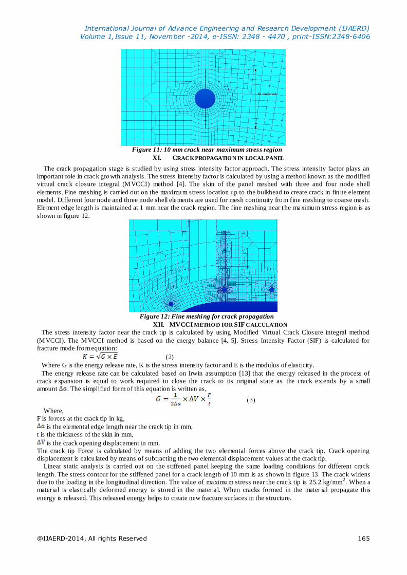
Figure 11: 10 mm crack near maximum stress region
XI. CRACK PROPAGATIO N IN LOCAL PANEL
The crack propagation stage is studied by using stress intensity factor approach. The stress intensity factor plays an
important role in crack growth analysis. The stress intensity factor is calculated by using a method known as the modified
virtual crack closure integral (MVCCI) method [4]. The skin of the panel meshed with three and four node shell
elements. Fine meshing is carried out on the maximum stress location up to the bulkhead to create crack in fin ite element
model. Different four node and three node shell elements are used for mesh continuity from fine meshing to coarse mesh.
Element edge length is maintained at 1 mm near the crack region. The fine meshing near t he maximum stress region is as
shown in figure 12.
Figure 12: Fine meshing for crack propagation
XII. MVCCI METHO D FOR SIF CALCULATION
The stress intensity factor near the crack tip is calculated by using Modified Virtual Crack Closure integral method
(MVCCI). The MVCCI method is based on the energy balance [4, 5]. St ress Intensity Factor (SIF) is calculated for
fracture mode from equation:
(2)
Where G is the energy release rate, K is the stress intensity factor and E is the modulus of elasticity.
The energy release rate can be calculated based on Irwin assumption [13] that the energy released in the process of
crack expansion is equal to work required to close the crack to its original state as the crack extends by a small
amount . The simplified form of this equation is written as,
(3)
Where,
F is fo rces at the crack tip in kg,
is the elemental edge length near the crack tip in mm,
t is the thickness of the skin in mm,
is the crack opening displacement in mm.
The crack tip Force is calculated by means of adding the two elemental forces above the crack tip. Crack opening
displacement is calcu lated by means of subtracting the two elemental displacement values at the crack tip.
Linear static analysis is carried out on the stiffened panel keeping the same loading conditions for different crack
length. The stress contour for the stiffened panel for a crack length of 10 mm is as shown in figure 13. The crack widens
due to the loading in the longitudinal direction. The value of maximum stress near the crack tip is 25.2 kg/mm2. When a
material is elastically deformed energy is stored in the material. When cracks formed in the mater ial propagate this
energy is released. This released energy helps to create new fracture surfaces in the structure.

International Journal of Advance Engineering and Research Development (IJAERD)
Volume 1,Issue 11, November -2014, e-ISSN: 2348 - 4470 , print-ISSN:2348-6406
@IJAERD-2014, All rights Reserved 166
Figure 13: Stress contour plot for 10 mm crack
Consider an example problem of crack length of 10 mm,
Crack opening displacement, ΔV = 0.0138 mm
Rack tip elemental force, F = 87.58 kg
Element edge length at the crack tip, Δa = 1 mm
Thickness of the skin at the crack tip, t = 4 mm
Strain energy release rate, G = 0.1514 Kg/mm,
Stress intensity factor, K = 32.55 Kg/mm2√mm
= 10.085 Mpa√m
The SIF is calcu lated for various crack length from 10 mm to the bulkhead position. The bulkhead is located at a
distance of 94 mm from window cut out region. The stress intensity factor is tabulated for various crack length as shown
in table below
Table II: Stress intensity Factor values for fuselage panel
Crack
length, 2a,
mm
COD ΔV in
mm
Crack t ip
Force F, in N
Energy release
rate in N/mm
G SIF, Mpa√m
10 0.0138 859.06 1.48 10.085
20 0.0395 1069.97 11.76 28.42
30 0.0375 1039.76 10.83 27.281
40 0.0378 1050.67 11.04 27.547
50 0.0386 1073.31 11.51 28.122
60 0.0397 1090.67 12.04 28.765
70 0.040 1107.45 12.38 29.106
80 0.0412 1133.05 12.96 29.837
85 0.0411 1125.20 12.81 29.651
90 0.0410 1104.40 12.57 29.387
94 0.0410 1103.87 12.57 29.301
From the table above it is clear that, the stress intensity factor increases as the crack grows. At 10 mm crack length the
stress intensity factor is 10.085 Mpa√m and increases to 29.362 Mpa√m at crack length of 94 mm. The maximum stress
intensity factor is 29.837 and is found to be at a crack length of 80 mm. The value of maximum stress intensity factor is
less than the fracture toughness of the material.
The condition for crack propagation is,
KI ≥ KIC (4)
Where, KI is the stress intensity factor found in FE analysis and KIC is the fracture toughness of the material. Fracture
toughness for Al-2024 for 1.8 mm thickness is 105.97 MPa√m and for 4 mm thickness is 98.97 MPa√m. From this we
can say that the fuselage is safe only when internal pressure acting along on the fuselage. But in actual case the fuselage
of an aircraft is subjected to different types of loads which include p ressurization and reaction load s, aerodynamic loads,
taxing loads and landing loads. Because of these loads acting the value of the stress intensity factor may exceed the
fracture toughness of the material and the crack propagates rapidly and finally leads to the catastrophic failure of the
fuselage. The damage tolerance design concept can be used to reduce this rapid failure. The use of bulkheads and
stringers are used to reduce the failure in this concept.
XIII. CRACK ARREST CAPABILITY O F BULKHEAD
The residual strength of damaged panels can be increased by using stringers and bulkheads. An unstable fast fracture
can be restricted to a local area by provid ing an area of low stress ahead of the crack t ip. The crack tip stress is reduced,
as a large part of the redistributed load is transferred into the bulkheads. Bulk heads are provided in the fuselage in such a
way that they oppose the leading crack. They are provided in the skin in the perpendicular direct ion of crack propagation.
The bulkheads used in a structure can increase the stiffness and static strength of the structure. The bulkheads are
connected to the skin by riveting. The cracks are possibly started at a rivet hole and propagate in both directions.

International Journal of Advance Engineering and Research Development (IJAERD)
Volume 1,Issue 11, November -2014, e-ISSN: 2348 - 4470 , print-ISSN:2348-6406
@IJAERD-2014, All rights Reserved 167
Design and location of bulk heads
The primary function of bulkhead is to arrest the longitudinal skin cracks, and principally they are designed for
arresting longitudinal cracks. The bulkheads are designed Z – section beams with a thickness of 4 mm as shown in figure
3. The material used for bulkheads are Aluminium 2024-T3. The bulkheads are provided in the fuselage panel in 400 mm
apart.
XIV. RESIDUAL STRENGTH ANALYSIS
The residual strength is the remain ing strength in a cracked structure. The residual strength calculation p lays an
important role in the crack propagation study.
Residual strength for skin
The residual strength are calculated by using the equation,
(5)
Where,
s remote is the remote stress acting on the panel = 42.18Mpa,
KI is the stress intensity factor,
KIC is the fracture toughness of the material.
For crack length of 10 mm,
Residual stress is calculated as,
= 413.97 Mpa
The residual strength is calculated for the skin in all crack length is as shown in table below:
Table III: Residual Strength of Skin
Crack length,
ΔC, mm
Residual strength,
s res, Mpa
10 413.97
20 157.29
30 163.81
40 162.27
50 158.96
60 155.40
70 153.58
80 149.82
85 150.76
90 152.11
94 152.24
Residual strength for Bulkhead
The residual strength of bulkheads is calculated using the following equation:
(6)
Where,
Ult imate tensile strength of Al 2024-T3 = 480 MPa
s remote= is the remote stress acting on the panel = 42.18MPa
smax = maximum stress on bulkhead
The residual strength is calculated for the bulkhead in all crack length is as shown in table below:
Table IV: Residual strength of bulkhead
Crack
length,
ΔC, mm
smax, maximum
stress on
bulkhead, MPa
Residual
strength, s res,
MPa
10 154.99 131.45
20 159.9 127.41
30 162.84 125.11
40 165.78 122.89
50 168.73 120.74
60 172.65 118.00
70 175.59 116.03
80 180.48 112.88
85 183.44 111.06
90 185.4 109.89

International Journal of Advance Engineering and Research Development (IJAERD)
Volume 1,Issue 11, November -2014, e-ISSN: 2348 - 4470 , print-ISSN:2348-6406
@IJAERD-2014, All rights Reserved 168
94 185.4 109.89
XV. RESULT AND DISCUSSIONS
1) Crack propagation study
Stress intensity factor for different crack length is plotted shown in figure 14. From the SIF vs crack length graph it is
observed that SIF value increases gradually when the crack length increases. When the crack reaches near the bulkhead
position there is a slight decrease in the SIF value. The maximum value of SIF is observed to be 29.83 Mpa√m at a crack
length of 80 mm and decreases to 29.362 when crack reaches the bulkhead position. This indicates that the bulkheads are
capable of arresting the further crack propagation.
Figure 14: SIF v/s crack length plot Figure 15: Residual strength plot-skin
2) Role of bulkhead to arrest crack
The residual strength of bulkheads are calculated by analytical calculations and plotted with variation in crack length.
From the crack length v/s residual strength graph of bulkhead it is observed that the residual strength decreases with
increase in crack length.
Fiureg 18: Residual strength plot- bulkhead
XVI. CO NCLUSION
The stress analysis carried out on the global fuselage panel shows that the maximum stress is near the cut out region.
Linear static stress analysis is carried on the local stiffened panel using MSC-Nastran and Patran software. The maximum
stress of 18.5 kg/mm2 is found to be on the rivet hole near the window cut-out region.
Stress analysis of the panel in the presence of crack is studied . MVCCI method is used for find out the stress intensity
factor on crack tip. Stress intensity factor is calcu lated for carious crack length. From SIF v/s crack length graph it is
observed that the SIF increases as a function of crack length. The SIF decreases when c rack approaches the bulkhead.
This shows that the load get transferred from skin to the bulkhead which may help in arresting the crack. SIF is compared
with the fracture toughness of the material to check whether the structure will lead to catastrophic failure or not.
Residual strength for skin and bulkhead is calcu lated for every crack length and plotted as a function of crack length. In
was observed that the residual strength of skin decreases when crack length increase. But the residual strength of the s kin
picks up slightly when the crack reaches the bulkhead position. This shows that the bulkheads used in the structure may
arrest further crack propagation.
XVII. ACKNOWLEDGEMENT
I wish to thank Prof. Subin P George, department of mechanical engineering at Amaljyothi College of Engineering,
Kottayam for guiding and encouraging me throughout the work. I would like to extend many thanks to our head of the
department Prof Sreekumar K, for supporting during course. Also sincere thanks to K. E. Girish, Director, Bangalore

International Journal of Advance Engineering and Research Development (IJAERD)
Volume 1,Issue 11, November -2014, e-ISSN: 2348 - 4470 , print-ISSN:2348-6406
@IJAERD-2014, All rights Reserved 169
aircraft industries limited, Bangalore for giving all available facilities and technology inputs during my work.
REFERENCES
[1] T. Swift, “Damage tolerance in pressurized fuselages,” 14th ICAF Syrup on New Materials and Fatigue Resistant
Aircraft Design, International Committee on Aeronautical Fat igue, Ottawa, Canada, 1987.
[2] M. Toor, “A review of some damage tolerance design approaches for aircraft structures,” Engineering Fracture
Mechanics, Volume. 5, pp. 837-880, 1973.
[3] W. Barro is. “Practical use of the „equivalent‟ measured stress intensity factor to control fatigue crack propagation
rates in aircraft fu ll-scale fat igue tests first assessment of the method in testing of a pressurized aircraft fuselage,”
engineering fracture mechanics, volume. 7, pp. 673-688, 1975
[4] E.F. Rybicki, M.F. Kanninen. “A finite element calcu lation of stress intensity factors by a modified crack closure
integral,” Engineering Fracture Mechanics, volume. 9, pp 931–938, 1977.
[5] R. Sethuraman and S.K.Maiti. “Finite Element Base Computation of Strain Energy Release Rate by Modified Crack
Closure Integral,” Engineering Fracture Mechanics, volume 30. No. 2, pp 227-231, 1988.
[6] M. Toor, “On Damage Tolerance Design of Fuselage Structure (Longitudinal cracks),” Engineering Fracture
Mechanics, volume. 24, Issue 6, pp.915-927, 1986.
[7] Bangyan Liu and Larry B. Lessard. “Fatigue and damage-tolerance analysis of composite laminates: Stiffness loss,
damage modelling, and life pred iction,” Composite science and technology, volume. 51, pp. 43 -50, 1994.


![Part1 Damage Tolerance Overview[1]](https://static.fdocuments.net/doc/165x107/5475a04fb4af9fb40a8b5cd2/part1-damage-tolerance-overview1.jpg)