Daikin VRV Installation - Goodman...
140
Daikin VRV Installation Participant Guide
Transcript of Daikin VRV Installation - Goodman...

Daikin
VRV Installation
Participant Guide

1/18/2013
1
© 2012 Daikin AC
RESIDENTIAL | LIGHT COMMERCIAL | COMMERCIAL
Training DepartmentSeptember 2012
DAIKIN VRV Product & Technology Introduction Review
DAIKIN VRV Product & Technology Introduction Review
© 2012 Daikin ACSlide 2
What is VRV® ?
� VRV - Daikin Registered trademark � Introduced in 1982 – Worlds first VRF system� Over 1 million installations worldwide� Over 25,000 systems in the US and Canada� Multiple Indoor units connected to one
condenser system� Air Cooled and Water Cooled systems� Ultra high comfort control and efficiency
Daikin VRV Concept
Variable - System capacity varies with load
Refrigerant - R-410A Direct Expansion System
Volume - Refrigerant flow regulated by EEV’sand a variable speed compressor
1/18/2013
2
© 2012 Daikin ACSlide 3
� Daikin VRV incorporates multiple technologies to provide ultra high energy savings, comfort control and reliability � Multiple indoor fan coils connected to
a single refrigerant network� Inverter control system to modulate
system capacity as loads change
� Heat Pump & Heat Recovery systems
Daikin VRV concept
Multiple Fan Coil Control + Inverter = Daikin VRV
1
© 2012 Daikin AC
VRV System Models VRVIII-S® VRVIII® VRV-WIII®
Condensers & Indoor Units
DAIKIN VRV Product &Technology IntroductionDAIKIN VRV Product &Technology Introduction
1/18/2013
3
© 2012 Daikin ACSlide 5
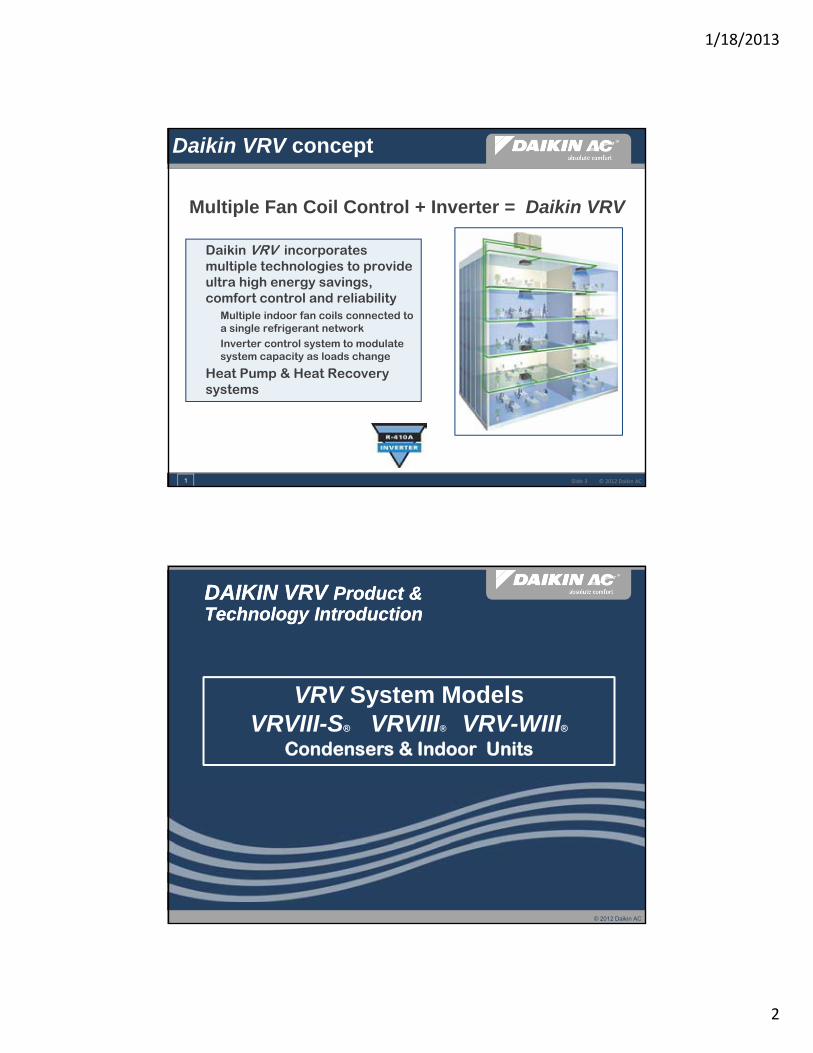
VRV Systems
208/230 vac Single Phase Heat Pump3 Ton & 4 Ton Models
Up to 14.9 SEER / HSPF 9.1
© 2012 Daikin ACSlide 6
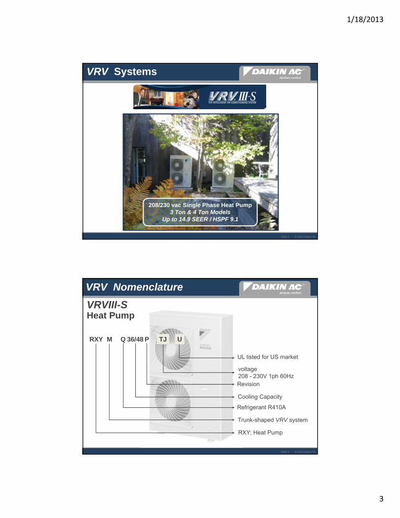
VRVIII‐S
RXY M Q 36/48
UL listed for US market
voltage 208 - 230V 1ph 60HzRevision
Cooling Capacity
Refrigerant R410A
Trunk-shaped VRV system
RXY: Heat Pump
VRV Nomenclature
P TJ U
VRVIII-SHeat Pump

1/18/2013
4
© 2012 Daikin ACSlide 7
VRV Systems
VRVIII‐S Heat Pump RXYMQ36&48P
� 208/230vac 1Ph - 30 amp power to Outdoor Unit� Outdoor unit Models: 36,000 & 48,000 Btu/h� Single Inverter scroll compressor� Indoor unit capacities 7,000 to 48,000 Btu/h� Single 2-Pipe refrigerant circuit� Connection of up to 6 or 8 indoor units� Connection ratio of 50% to 130% possible� 1000’ - Maximum refrigerant piping length� Operating Range – Cool: 23° to 115°F Heat: 0 ° to 77 °F
7
© 2012 Daikin ACSlide 8
VRV Systems
208/230 & 460vac Three Phase Heat Pump & Heat Recovery Models
6 to 30 Ton Systems

1/18/2013
5
© 2012 Daikin ACSlide 9
VRVIII Heat Pump
RXY Q ##
208/230vac 3ph 60Hz
Revision
Cooling Capacity
Refrigerant R410A
Air Cooled Heat Pump
VRV Nomenclature
Heat Pump condensers are manufactured to be single piped or manifolded (Excl. RXYQ144PBTJ)
460vac 3ph 60Hz
PB TJ or YD
© 2012 Daikin ACSlide 10
VRVIII Heat Recovery Single Piped
REY Q ##
208/230vac 3ph 60Hz
Revision
Cooling Capacity
Refrigerant R410A
Air Cooled Heat Recovery
VRV Nomenclature
REYQ Heat Recovery condensers are manufactured to be single piped only: 6,8,10 & 12 ton (Excl. REYQ144PBYD)
460vac 3ph 60Hz
PB TJ or YD

1/18/2013
6
© 2012 Daikin ACSlide 11
VRVIII Heat Recovery Manifolded Module
REM Q ##
208/230vac 3ph 60Hz
Revision
Cooling Capacity
Refrigerant R410A
Air Cooled Heat Recovery Manifolded Module
VRV Nomenclature
REMQ Heat Recovery condensers are manufactured to be manifolded only: 6,8,10 & 12 ton (Excl. REYQ144PBTJ)
460vac 3ph 60Hz
PB TJ or YD
© 2012 Daikin ACSlide 12
VRV Systems
� 208/230vac 3ph and 460vac 3ph models� Heat Pump and Heat Recovery models� Dual scroll compressors – 1 Inverter and 1 Standard
� Excl. 6 ton HP & HR units & 12 ton 208/230vac. units
� System capacities: HP 6 – 30 Ton / HR 6 – 28 Ton� Connection of up to 62 indoor units � Connection ratio of 50% to 200% possible� 3,280’ - Maximum refrigerant piping length� Operating Range: Cool: 23° to 115°F Heat: 0° to 77°F
VRV III RXYQ & REY(M)Q
6

1/18/2013
7
© 2012 Daikin ACSlide 13
VRV Systems
208/230 vac. 3 Phase 460 vac. 3 Phase
Heat Pump / Heat Recovery 6 to 21 Ton Systems
© 2012 Daikin ACSlide 14
RWEY Q 72/84 P TJ YD U or N
208/230vac 3ph 60Hz
Revision
Cooling Capacity
Refrigerant - R410A
Water-cooled type
Same unit model is used for Heat Pump - Heat Recovery & Geothermal operation.
VRV-WIII
VRV Nomenclature
460vac 3ph 60Hz

1/18/2013
8
© 2012 Daikin ACSlide 15
� 208/230vac & 460vac 3 phase models� 6 & 7 ton single condenser models
� Heat Pump / Heat Recovery operation� Geothermal
� Single inverter scroll compressor� System capacities: 6 to 21 ton� Standard EWT: 60°F to 113°F
� Geothermal EWT: 14°F (heat)
� Max. refrigerant piping length: 980 ft.� Connection of up to 12 – 32 fan coils� Standard connection ratio: 50% to 130%
VRV Systems
VRV-WIIIWater Cooled RWEYQ_P
Field Configured Geothermal Operation
Interior Installation Only
6
© 2012 Daikin ACSlide 16
Indoor Units
VRV Systems
12 Types 55 Models
3’X3’ Ceiling Cassette 2’X2’ Ceiling Cassette Wallmount
Unitary Ducted Exposed & Concealed Floor Standing Ceiling Suspended
6 & 8 Ton Med Static Ducted
Med Static DC Ducted
Low Static Slim Duct Concealed
100% Outside Air Processing Unit
Energy Recovery Ventilator
All 208/230vac 1 Phase powered

1/18/2013
9
© 2012 Daikin AC
VRV Basic Controls
DAIKIN VRV Product &Technology IntroductionDAIKIN VRV Product &Technology Introduction
© 2012 Daikin ACSlide 18
Local Remote Controllers
VRV Basic Controls
BRC2A71 BRC7C/7E/4CBRC1E71
Navigation Remote Controller Simplified Hand-heldWireless
DIII – NET 16vdc digital control network

1/18/2013
10
© 2012 Daikin ACSlide 19
Remote Sensor KRCS01-1B (4B)
� VRV Fan Coil Units incorporate a built‐in return air thermistor temperature sensor as standard (excl. FXTQ)� KRCS01‐1B (4B) Remote Sensor is offered to replace the return air thermistor
when:� Outside fresh air is brought in to the fan coil return air
� Ceiling height of fan coil return is 13ft or more
� Above ceiling plenum return is used
� Standard 39ft cable ‐ Plenum Rated 40ft and 80ft cable optional
NOTE: KRCS01-4B Remote Sensor Kit for FXMQ_P, FXFQ_P and FXTQ Fan Coil Units
VRV Basic Controls
4
© 2012 Daikin AC
VRV System Types
Heat Pump / Heat Recovery
DAIKIN VRV Product &Technology IntroductionDAIKIN VRV Product &Technology Introduction
1/18/2013
11
© 2012 Daikin ACSlide 21
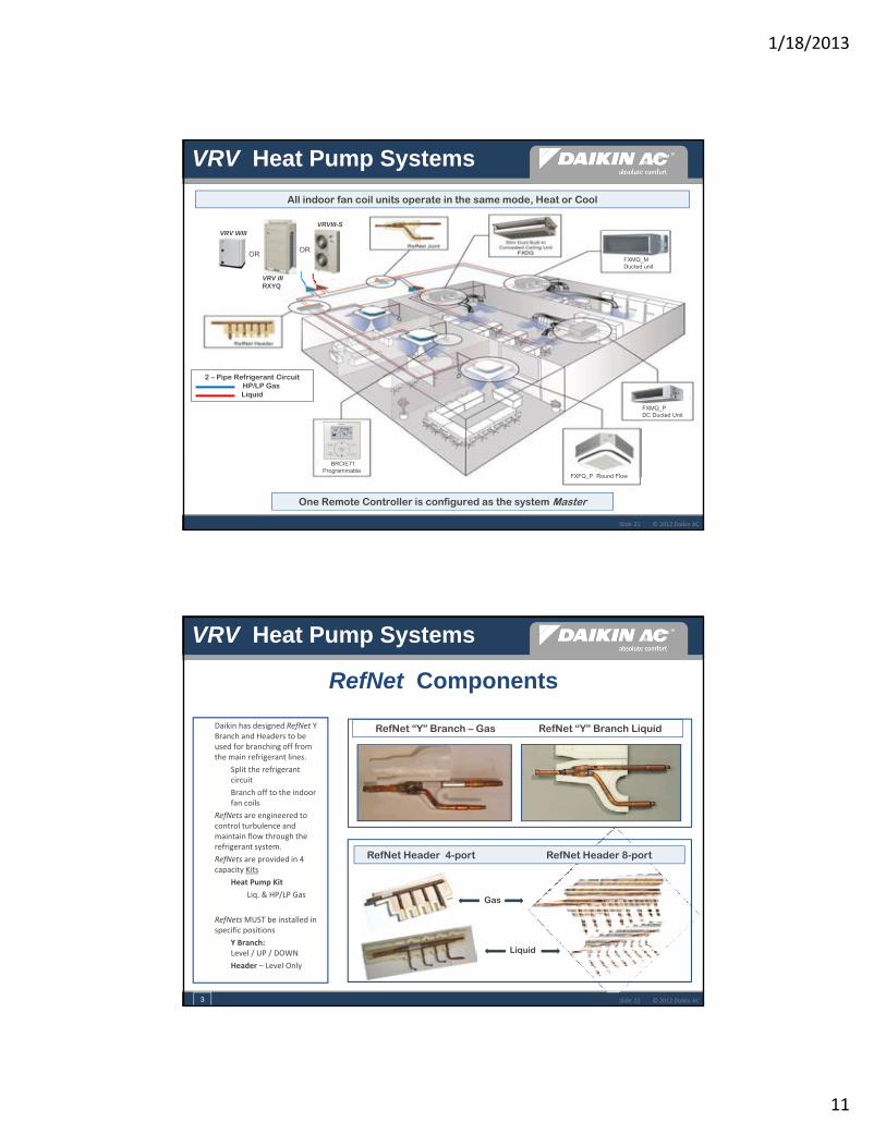
All indoor fan coil units operate in the same mode, Heat or Cool
OROR
VRV WIII
VRV IIIRXYQ
VRVIII-S
FXMQ_M Ducted unit
FXMQ_P DC Ducted Unit
BRCIE71 Programmable
FXFQ_P Round Flow
2 – Pipe Refrigerant CircuitHP/LP Gas Liquid
VRV Heat Pump Systems
One Remote Controller is configured as the system Master
© 2012 Daikin ACSlide 22
� Daikin has designed RefNet Y Branch and Headers to be used for branching off from the main refrigerant lines.
� Split the refrigerant circuit
� Branch off to the indoor fan coils
� RefNets are engineered to control turbulence and maintain flow through the refrigerant system.
� RefNets are provided in 4 capacity Kits
� Heat Pump Kit
� Liq. & HP/LP Gas
� RefNetsMUST be installed in specific positions
� Y Branch: Level / UP / DOWN
� Header – Level Only
VRV Heat Pump Systems
RefNet Components
RefNet “Y” Branch – Gas RefNet “Y” Branch Liquid
RefNet Header 4-port RefNet Header 8-port
Liquid
Gas
3

1/18/2013
12
© 2012 Daikin ACSlide 23
Daikin DIII-Net Architecture
Heat Pump Transmission wiring
� The DIII‐Net communications is proprietary to Daikin VRV systems
� Simple 2 conductor wire, non polarity sensitive, 16vdc communications circuit
� 16/18 awg. 2-conductor stranded, non-shielded
� Daisy chain wiring to all system components
� Maximum system control wire length: 6,600 ft.
VRV Heat Pump Systems
© 2012 Daikin ACSlide 24
Control Circuit Terminal Designations
� Fan Coil Control Terminal Circuits� P1 P2 – Fan Coil to Remote Controller
� Remote Controller power supply and data transfer
� F1 F2 – Communications from condenser to all Fan Coils
� T1 T2 – Forced Off (Default N.O.) External Contacts
All VRV Fan Coils
VRVIII-SVRVIII – VRV-WIII
VRV Heat Pump Systems
� Condenser Control Terminal Circuits� F1 F2 In – Condenser to Fan Coils
� F1 F2 Out – Multi-Zone Control� iTouch
� iTouch Manager
� Gateway – LON Works or BACnet
� Q1 Q2 (VRVIII & VRV-WIII) – Manifolded Modules
1
1/18/2013
13
© 2012 Daikin ACSlide 25
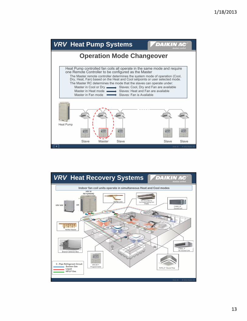
Operation Mode Changeover
� Heat Pump controlled fan coils all operate in the same mode and require one Remote Controller to be configured as the Master� The Master remote controller determines the system mode of operation (Cool,
Dry, Heat, Fan) based on the Heat and Cool setpoints or user selected mode.� The Master RC determines the mode that the slaves can operate under:
� Master in Cool or Dry Slaves: Cool, Dry and Fan are available� Master in Heat mode Slaves: Heat and Fan are available� Master in Fan mode Slaves: Fan is Available
Slave Master Slave Slave Slave
Heat Pump
VRV Heat Pump Systems
4
© 2012 Daikin ACSlide 26
Indoor fan coil units operate in simultaneous Heat and Cool modes
BRCIE71 Programmable
FXMQ_M Ducted unit
FXMQ_P DC Ducted Unit
FXFQ_P Round Flow
Branch Selector Box
ORVRV WIII
VRV III REYQ/REMQ
3 – Pipe Refrigerant CircuitSuction Gas Liquid HP/LP Gas
VRV Heat Recovery Systems

1/18/2013
14
© 2012 Daikin ACSlide 27
EEV
EEV’s
Liquid pipe
Suction gas pipe
HP/LP Gas Pipe
Branch Selector Box
Single Port Model Numbers:BSVQ36PVJU 36,000 Btu - Up to 5 FC’s BSVQ60PVJU 60,000 Btu - Up to 8 FC’s BSVQ96PVJU 96,000 Btu - Up to 8 FC’s
� Provides Heating/Cooling changeover to the connected fan coil or fan coils
� EEV refrigerant control
� Brazed refrigerant connections
� 208/230vac 1 ph. powered208-230vac.
VRV Heat Recovery Systems
1
© 2012 Daikin ACSlide 28
Operation Mode Changeover
� When two or more Fan Coils with dedicated Remote Controllers are connected to one BS-Box, one of the Remote Controllers must be configured as the Master� Master determines the BS-Box operation mode� The Slave indoor units follow the Master’s operation mode
Slave Master Slave
Heat RecoveryBS-Box BS-Box BS-Box
Master Master
VRV Heat Recovery Systems

1/18/2013
15
© 2012 Daikin ACSlide 29
Branch Selector Control Circuits
Transmission wiring
� Same 2 conductor control wire used to connect all Branch Selectors to Condenser
� F1 F2 In daisy chain wired from Condenser terminal block to F1 F2 Out on Branch Selectors
� F1 F2 In from Branch Selector to F1 F2 on connected fan coil(s)
VRV Heat Recovery Systems
BS-Box BS-BoxBS-Box BS-Box
BSVQ__P
1
F1 F2 IN
© 2012 Daikin AC
DAIKIN VRV Product &Technology IntroductionDAIKIN VRV Product &Technology Introduction
VRV Refrigerant Piping Lengths

1/18/2013
16
© 2012 Daikin ACSlide 31
RefNet Piping Length Requirements
�The Standard maximum distance from the first RefNet to the farthest fan coil is 130ft.� Exception: VRV III can be extended to 295ft from the
first RefNet to the farthest fan coil: rules apply� All Branch runs must be 130ft or less from a RefNet
“Y” or RefNet Header, to the fan coil.� No requirement for Branch Selector Box
VRV Refrigerant Piping
4
130 ft.
© 2012 Daikin AC
VRV Basic System Control Operations
DAIKIN VRV Product &Technology IntroductionDAIKIN VRV Product &Technology Introduction

1/18/2013
17
© 2012 Daikin ACSlide 33
Compressor Capacity Control
� Sets Target low & high pressure values at the Condenser
� Sets the Target evap. & cond. Temps in the indoor Fan Coils
� Local Remote Controllers initiate a system Thermo-ON with a 1°deviation from set point
� Local Remote Controllers initiate a system Thermo-OFF when all set points are reached
Control System
52~210HzApplied frequency
37 Applied Capacity Steps
14%
100%
Inverter ControlAdjusts compressor speed (capacity) up or down to correct deviation from the target pressure values (system load)
VRVIII Single 8 & 10 Ton
� COOL Operation� Detects the system operating
suction pressure at the condenser once every 20 seconds & Target Evap temp
� HEAT Operation� Detects the system operating
high pressure at the condenser once every 20 seconds & Target Cond temp
Condenser Control
VRV Basic System Control
2
© 2012 Daikin ACSlide 34
� VRV fan coils have 3 thermistor sensors (excl. FXTQ & FXMQ_MF)
� The sensor signals are used to regulate refrigerant volume through the fan coil using Proportional, Integral & Derivative (PID) control, to correct deviation from target temperature values by adjusting the Electronic Expansion Valve in pulses to modulate open and close
R1T
Liq. pipe
HP/LP Gas pipe
Main PCB
SENSOR LEGENDR1T: Return AirR2T: Saturated Liquid Pipe R3T: Gas PipeTH1: Remote Controller SensorTSET: Remote Controller Set Point
R2T TH1
H or C Temp Setpoint
TSET
EEV
Indoor Fan Coil Unit
Electronic Expansion Valve Control
R3T
VRV Basic System Control
1

1/18/2013
18
© 2012 Daikin ACSlide 35
Basic Fan Coil Control� Blower cycling
� Constant Fan – User selectable speeds: L – H – (HH)
� COOL mode – User selectable (Thermo‐ON & Thermo‐OFF)
� HEAT mode – Thermo‐ON ‐ User selectable / Thermo OFF – LL
� Fan Auto Setting (“P” series fan coils only)
� Blower cycling may be reprogrammed in the field
� Electronic Expansion Valve� Modulates from 0 to 2000 pulses (PID control)
� COOL mode
� Thermo‐ON ‐ Modulates to maintain target superheat temperatures
� Thermo‐OFF – Closes (0 pulse)
� HEAT mode
� Thermo‐ON – Modulates to maintain target subcooled temperatures
� Thermo‐OFF – Minimum Open (200 pulses approx)
� Condensate Lift Pump (FXFQ FXZQ FXDQ FXMQ_P)
� COOL Thermo‐ON – Constant operation
� COOL Thermo‐OFF‐ 5 minute residual operation then OFF
� Control PCB (A1P)� Field Settings programmed from RC reside in permanent memory
� Contains unit control address and Group Address
VRV Basic System Control
4
© 2012 Daikin ACSlide 36
VRVIII-S Heat Pump RXYMQ36/48PVJU Single Phase
Smooth Sine Wave Inverter
Single Reluctance Digitally Commutated Daikin G2 Scroll Compressor
70 watt tandem modulating DC Fan Motors Low Pressure Loss Bellmouth with
Aero Spiral Fans
Digital Microprocessor● Simple system commissioning at control PCB
Standard VRV Control Operations● Auto Addressing ● Check Operation Mode ● Pump Down Residual ● Time/Temp Defrost ● Restart Standby ● Crankcase Heater Control
VRV Basic System Control
1/18/2013
19
© 2012 Daikin ACSlide 37
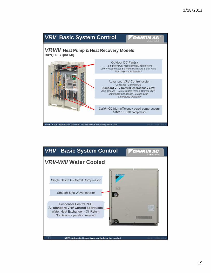
VRVIII Heat Pump & Heat Recovery ModelsRXYQ REYQ/REMQ
Outdoor DC Fan(s)Single or Dual modulating DC fan motors
Low Pressure Loss Bellmouth with Aero Spiral FansField Adjustable Fan ESP
Advanced VRV Control systemCondenser Control PCB
Standard VRV Control Operations PLUS:Auto Charge – Uninterrupted Heat in Defrost (HR)
Manifolded Condenser Rotation Start Emergency Operation
Daikin G2 high efficiency scroll compressors1-INV & 1 STD compressor
NOTE: 6 Ton Heat Pump Condenser has one Inverter scroll compressor only
VRV Basic System Control
© 2012 Daikin ACSlide 38
VRV-WIII Water Cooled
Single Daikin G2 Scroll Compressor
Smooth Sine Wave Inverter
Condenser Control PCBAll standard VRV Control operations
Water Heat Exchanger - Oil ReturnNo Defrost operation needed
NOTE: Automatic Charge is not available for this product
VRV Basic System Control
1

1/18/2013
20
© 2012 Daikin AC
DAIKIN VRV Product &Technology IntroductionDAIKIN VRV Product &Technology Introduction
VRV Multi-Zone Control Systems
© 2012 Daikin ACSlide 40
Multi-Zone Control Systems
VRV Multi-Zone Controls
Centralized Controller Unified On/Off Schedule Timer
1/18/2013
21
© 2012 Daikin ACSlide 41
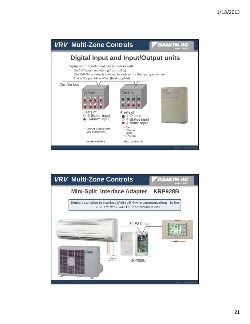
Digital Input and Input/Output units� Equipment is controlled like an indoor unit
� On / Off based monitoring / controlling� One DIII‐Net address is assigned to each set for third party equipment� Power Supply: 24vac 40va (field supplied)
Di Unit Dio Unit
DIII-Net bus
8 sets of 8-Status input8-Alarm input
4 sets of 4-Output4-Status input4-Alarm input
• Fan• Damper• Light• AHU etc
• On/Off Status from any equipment
VRV Multi-Zone Controls
DEC101A51-US2 DEC102A51-US2
© 2012 Daikin ACSlide 42
Simple installation to interface Mini‐split 4‐wire communications to the VRV D‐III Net 2‐wire F1 F2 communications
Mini-Split Interface Adapter KRP928B
KRP928B
F1 F2 Circuit
1 2 3 Gnd
L1 L2 Line & 12-45 vdc
VRV Multi-Zone Controls

1/18/2013
22
© 2012 Daikin AC
Thank YouPT‐VRV‐1211‐PP1‐01A

1
© 2010 Daikin AC
VRVBasic System Installation
Training Department
May 2011
© 2005 Daikin ACSlide 2Presentation Title : Presenter Name : Date © 2010 Daikin ACSlide 2
VRVBasic System Installation Agenda
� VRV – Basic Refrigerant Piping� Piping Layout
� Refrigerant Components
� Basic piping length requirements
� Xpress Piping Report
� VRV – Basic Piping Installation� Piping Installation Recommendations
� VRVIII Manifolded systems
� Pressure Equalization piping
� VRV – Indoor Units� Fan Coil Installation
� Branch Selector Box Installation
� VRV – Controls and Control Wiring� Local Remote Controls
� Control Circuits
� Xpress Wiring Report
� VRV – Condenser Basic Installation

2
© 2010 Daikin AC
VRV Basic Refrigerant PipingSpecifications & Installation
© 2005 Daikin ACSlide 4Presentation Title : Presenter Name : Date © 2010 Daikin ACSlide 4
Liquid pipe Gas pipe
VRV WIII
VRV IIIRXYQ
VRVIII-S
Heat Pump operation: All indoor fan coils operate in the same mode
The Daikin RefNets are required to branch offrefrigerant for the Liquid and Gas line, to each Fan Coilunit, and when splitting off the refrigerant circuit.
VRVHeat Pump Refrigerant Piping

3
© 2005 Daikin ACSlide 5Presentation Title : Presenter Name : Date © 2010 Daikin ACSlide 5
One system provides simultaneous cooling and heating
BSVQ _VRVIII
OR
Branch Selector Box
VRV WII
VRV III REYQ
VRVHeat Recovery Refrigerant Piping
The Daikin RefNets are required to branch off refrigerant for the Liquid and Gas lines, to each Branch Selector Box, Fan Coil unit and circuit
3-Pipe refrigerant system
© 2005 Daikin ACSlide 6Presentation Title : Presenter Name : Date © 2010 Daikin ACSlide 6
RefNet Components
RefNet “Y” Branch – Gas & Liquid KitRefNet Header Gas & Liquid Kit
4-Port & 8-Port

4
© 2005 Daikin ACSlide 7Presentation Title : Presenter Name : Date © 2010 Daikin ACSlide 7
VRV RefNet “Y” Joint Installation
♦ RefNet Y Joints to be installed: straight up - straight down – level (+/- 15°)
♦ Each RefNet included in the branch kit is labeled to identify circuit:
Liquid – Gas – Suction (HR)
© 2005 Daikin ACSlide 8Presentation Title : Presenter Name : Date © 2010 Daikin ACSlide 8
VRV RefNet Header Installation
Gas Model
Liquid Model
Outdoor unit side
Branch side
♦ RefNet Headers must be installed in a level position only
♦ Properly support headers to insure solid installation
♦ Refrigerant circuit is terminated at header (Deadhead)
♦ Unused branch ports are to be brazed closed
♦ Each RefNet included in the branch kit is labeled to identify
circuit: Liquid – Gas – Suction

5
© 2005 Daikin ACSlide 9Presentation Title : Presenter Name : Date © 2010 Daikin ACSlide 9
RefNet “Y” - Position vs. Flow Demonstration
© 2005 Daikin ACSlide 10Presentation Title : Presenter Name : Date © 2010 Daikin ACSlide 10
Refrigerant flow demonstration
6
© 2005 Daikin ACSlide 11Presentation Title : Presenter Name : Date © 2010 Daikin ACSlide 11
VRVRefNet Branch Kits
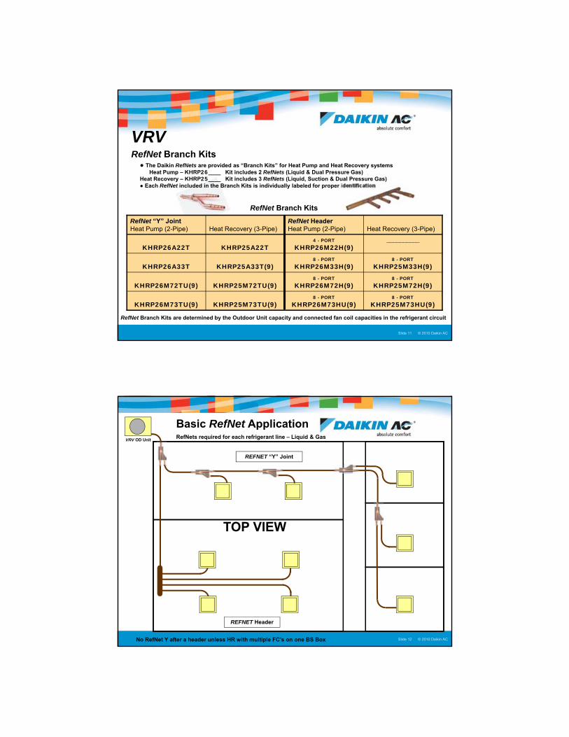
● The Daikin RefNets are provided as “Branch Kits” for Heat Pump and Heat Recovery systemsHeat Pump – KHRP26____ Kit includes 2 RefNets (Liquid & Dual Pressure Gas)
Heat Recovery – KHRP25____ Kit includes 3 RefNets (Liquid, Suction & Dual Pressure Gas)● Each RefNet included in the Branch Kits is individually labeled for proper identification
RefNet “Y” JointHeat Pump (2-Pipe) Heat Recovery (3-Pipe)
RefNet HeaderHeat Pump (2-Pipe) Heat Recovery (3-Pipe)
KHRP26A22T KHRP25A22T4 - PORT
KHRP26M22H(9)__________
KHRP26A33T KHRP25A33T(9)8 - PORT
KHRP26M33H(9)8 - PORT
KHRP25M33H(9)
KHRP26M72TU(9) KHRP25M72TU(9)8 - PORT
KHRP26M72H(9)8 - PORT
KHRP25M72H(9)
KHRP26M73TU(9) KHRP25M73TU(9)8 - PORT
KHRP26M73HU(9)8 - PORT
KHRP25M73HU(9)
RefNet Branch Kits
RefNet Branch Kits are determined by the Outdoor Unit capacity and connected fan coil capacities in the refrigerant circuit
© 2005 Daikin ACSlide 12Presentation Title : Presenter Name : Date © 2010 Daikin ACSlide 12
REFNET Header
Basic RefNet ApplicationRefNets required for each refrigerant line – Liquid & Gas
REFNET “Y” Joint
VRV OD Unit
No RefNet Y after a header unless HR with multiple FC’s on one BS Box
TOP VIEW
7
© 2010 Daikin AC
Basic VRV Piping Rules
© 2005 Daikin ACSlide 14Presentation Title : Presenter Name : Date © 2010 Daikin ACSlide 14
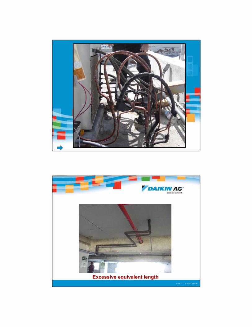
Excessive equivalent length
8
© 2005 Daikin ACSlide 15Presentation Title : Presenter Name : Date © 2010 Daikin ACSlide 15
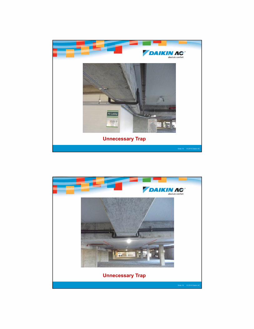
Unnecessary Trap
© 2005 Daikin ACSlide 16Presentation Title : Presenter Name : Date © 2010 Daikin ACSlide 16
Unnecessary Trap
9
© 2005 Daikin ACSlide 17Presentation Title : Presenter Name : Date © 2010 Daikin ACSlide 17
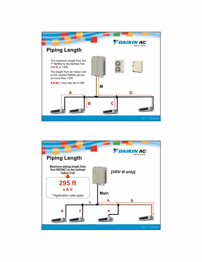
M
D
B C
A
� The maximum length from the 1st RefNet to the farthest Fan Coil D, is 130ft.
� The length from an Indoor unit to the nearest RefNet can be no more than 130ft
� A,B,&C, must also be ≤130ft
Piping Length
© 2005 Daikin ACSlide 18Presentation Title : Presenter Name : Date © 2010 Daikin ACSlide 18
Main
c b
f ed
a
Maximum piping length from first REFNET to the furthest
Indoor Coil
295 fta & b
**Application rules apply
Piping Length
[VRV III only]

10
© 2005 Daikin ACSlide 19Presentation Title : Presenter Name : Date © 2010 Daikin ACSlide 19
�The Longest (a+b) can be a maximum of 295ft
�Only if Shortest (c+f) = 165ft or more
M
c b
f e
d a295 ft
> 165 ft
(Longest – Shortest) is ≤130ft Otherwise 130ft max
Piping Length
[VRV III only]
© 2005 Daikin ACSlide 20Presentation Title : Presenter Name : Date © 2010 Daikin ACSlide 20
A B C D
e f g h i j
M
�If the outdoor unit to the furthest indoor unit has an equivalent length of ≥295 ft the main line (M) must be upsized
�Heat Pump – Liquid & Gas Pipes
�Heat Recovery – Liquid Pipe only
Main Piping Size
REYQ72 φ 3/8 φ 1/2
REYQ96 φ 3/8 φ 1/2
REYQ120 φ 1/2 φ 5/8
REYQ144 φ 1/2 φ 5/8
REYQ168 φ 5/8 φ 3/4
REYQ192 φ 5/8 φ 3/4
REYQ216 φ 5/8 φ 3/4
REYQ240 φ 5/8 φ 3/4
Liquid
Std One Size Up
RXYQ72 φ 3/4 φ 7/8 φ 3/8 φ 1/2
RXYQ96 φ 7/8 N/A φ 3/8 φ 1/2
RXYQ120 φ 1 1/8 φ 1/2 φ 5/8
RXYQ144 φ 1 1/8 φ 1/2 φ 5/8
RXYQ168 φ 1 1/8 φ 5/8 φ 3/4
RXYQ192 φ 1 1/8 φ 5/8 φ 3/4
RXYQ216 φ 1 1/8 φ 5/8 φ 3/4
RXYQ240 φ 1 3/8 φ 5/8 φ 3/4
Suction gas Liquid
Std One Size Up Std One Size Up
N/A
N/A
N/A
N/A
N/A
N/A

11
© 2005 Daikin ACSlide 21Presentation Title : Presenter Name : Date © 2010 Daikin ACSlide 21
M
c b
f e
d a
� If from the first REFNET to an indoor unit exceeds 130ft, all pipes between the first REFNET and the REFNET serving the indoor unit over 130ft must be upsized (a)
� If the upsized pipe size is larger than the main pipes (M), the main must also be upsized
� To calculate total piping the actual length of the upsized piping must be doubled excluding main line (M)
Piping Size (O.D)
Pipe Size ø One Size Up ø
3/8 1/2
1/2 5/8
5/8 3/4
3/4 7/8
7/8 N/A
1-1/8 N/A
1-3/8 N/A
1-5/8 N/A
Long Piping Lengths
© 2005 Daikin ACSlide 22Presentation Title : Presenter Name : Date © 2010 Daikin ACSlide 22
A B C D
e f g h i j
M
e = 120ft, this is within the ≤130ft limit from an indoor unit to the nearest REFNET (f, g, h, i & j must also follow this rule)
A +B +C +D +j (longest length)=200ft, the difference between the longest and shortest (e) is 80ft, this is within the limitations (longest – shortest ≤130ft)
A+B+C+D+i = 160ft, from the first REFNET to indoor (i) is over 130ft so the liquid and gas pipes must be upsized between REFNETS (A+B+C+D only) (HP/LP pipe is also upsized on a Heat Recovery System)
When calculating total actual pipe length in the example below M+2A+2B+2C+2D+e+f+g+h+i+j ≤3,280 ft
120ft
200ft
Piping Length
160ft
12
© 2005 Daikin ACSlide 23Presentation Title : Presenter Name : Date © 2010 Daikin ACSlide 23
VRV Xpress Piping Report
© 2005 Daikin ACSlide 24Presentation Title : Presenter Name : Date © 2010 Daikin ACSlide 24
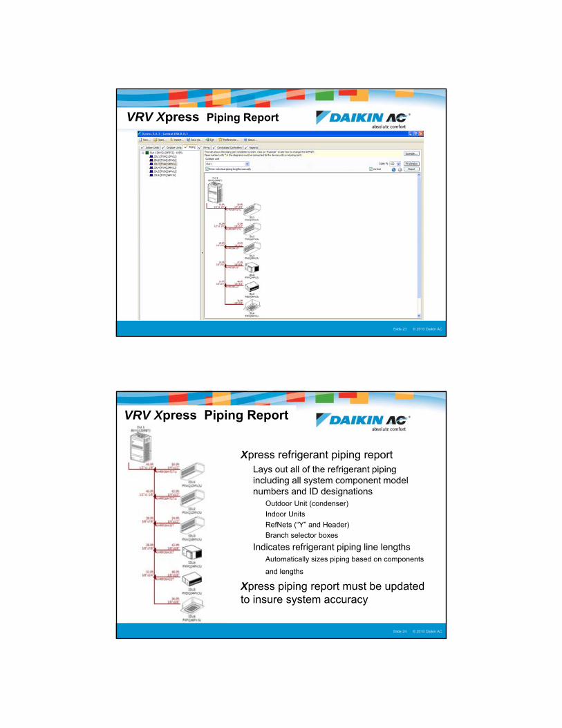
VRV Xpress Piping Report
�Xpress refrigerant piping report�Lays out all of the refrigerant piping
including all system component model numbers and ID designations� Outdoor Unit (condenser)
� Indoor Units
� RefNets (“Y” and Header)
� Branch selector boxes
�Indicates refrigerant piping line lengths� Automatically sizes piping based on components
and lengths
�Xpress piping report must be updated to insure system accuracy

13
© 2005 Daikin ACSlide 25Presentation Title : Presenter Name : Date © 2010 Daikin ACSlide 25
VRV Xpress Piping Report
© 2010 Daikin AC
VRV Piping Installation

14
© 2005 Daikin ACSlide 27Presentation Title : Presenter Name : Date © 2010 Daikin ACSlide 27
VRV III Piping Accessories
Supplied Copper fitting accessories for the Outdoor Unit
© 2005 Daikin ACSlide 28Presentation Title : Presenter Name : Date © 2010 Daikin ACSlide 28
� The Liquid and Gas piping must be completely insulated� Recommended wall thickness – 3/4”
� All flare connections must be insulated
VRV Refrigerant Piping
Fan Coil Installation Kit

15
© 2005 Daikin ACSlide 29Presentation Title : Presenter Name : Date © 2010 Daikin ACSlide 29
VRV Refrigerant Piping� VRV Refrigerant piping installation procedures
� Keep refrigerant piping clean and sealed during installation� Use Nitrogen purge during brazing process
� Eliminate debris contamination in refrigerant piping
� Installation period less than 30 days – pinch/braze or tape ends
� Installation period more than 30 days – pinch/braze ends
� Refrigerant piping must be properly insulated� Recommended ¾” wall insulation
� Liquid and Gas pipes must be individually insulated
� All Flare nut connections must be insulated
� Refrigerant piping must be properly supported� Follow local code requirements for piping support locations
� Support piping within 12” of BS Box and Fan Coil unit
� Keep track of each refrigerant circuit during installation� Measure liquid lines as they are installed
� Avoid crossing refrigerant lines during installation
© 2005 Daikin ACSlide 30Presentation Title : Presenter Name : Date © 2010 Daikin ACSlide 30
>20”
>40”>20”
VRV RefNet Installation recommendations
oror
� 90° Elbows should be kept 20” from Fan Coils & BS Boxes
� 90° Elbows should be kept 20” from RefNets & Headers
� RefNet “Y” and or Headers should be kept 40” from each other
� There is no minimum distance between BS Boxes & Fan Coils, but above rules and good piping practices should be followed
NOTE: This procedure is recommended to avert potential noise issues in the piping
16
© 2010 Daikin AC
VRV III Manifolded SystemRefrigerant Piping
© 2005 Daikin ACSlide 32Presentation Title : Presenter Name : Date © 2010 Daikin ACSlide 32
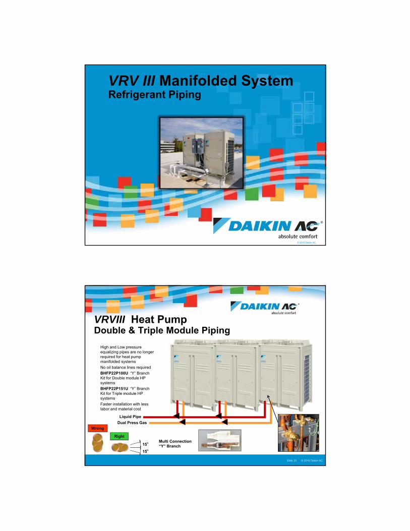
� High and Low pressure equalizing pipes are no longer required for heat pump manifolded systems
� No oil balance lines required
� BHFP22P100U “Y” Branch Kit for Double module HP systems
� BHFP22P151U “Y” Branch Kit for Triple module HP systems
� Faster installation with less labor and material cost
VRVIII Heat Pump Double & Triple Module Piping
Liquid Pipe
Multi Connection “Y” Branch
Dual Press Gas
Wrong
Right
15°
15°

17
© 2005 Daikin ACSlide 33Presentation Title : Presenter Name : Date © 2010 Daikin ACSlide 33
� Double & Triple manifolded Heat Recovery modules require a ¾” HP/LP Pressure Equalization pipe
� Uninterrupted Heat operation in the defrost mode
� BHFP26P90U “Y” Branch Kit for double module HR systems
� BHFP26P136U “Y” Branch Kit for triple module HR systems
Liquid Pipe
Suction
Dual Press Gas
HP/LP Equalization Pipe ¾”
Multi Connection “Y” Branch
VRVIII Heat Recovery Double & Triple Module Piping
Wrong
Right
15°
15°
© 2005 Daikin ACSlide 34Presentation Title : Presenter Name : Date © 2010 Daikin ACSlide 34
VRVIII Xpress Manifolded system Piping Report

18
© 2005 Daikin ACSlide 35Presentation Title : Presenter Name : Date © 2010 Daikin ACSlide 35
When a single condenser module is operating due to low load, refrigerant is bypassed to the other condenser through the pressure equalizing pipe. By utilizing both heat exchangers part load energy efficiency is improved
Outdoor unit 1 Outdoor unit 2
Partial Loadoperation
Liquid pipe
Suction gas pipe
High/low pressure gas pipe
Equalizing pressure pipe
Higher efficiency by increasing coil surface area
VRVIII Equalizing Pressure Pipe – Heat Recovery
NOTE: No Equalizer circuits on Heat Pump Models (“PB” series)
© 2005 Daikin ACSlide 36Presentation Title : Presenter Name : Date © 2010 Daikin ACSlide 36
VRVIII Manifolded Systems Module Interconnecting Piping Lengths
� Traps are installed on Gas line(s) only
� Traps must have a minimum of an 8 in. rise
� Inverted oil traps are only required when manifolded VRVIII condensers have a horizontal separation of 6.5 ft. to 33 ft. measured from the First “Y” Branch to Module
Up to 6.5ft Separation No Trap Required
Multi Connection “Y” Branch
Inverted Trap within 6.5 ft.
Greater than 6.5ft, less than 33ft Inverted Oil Trap required on Gas line(s)
> 8”
Multi Connection “Y” Branch
NOTE: Refer to condenser installation manual for all refrigerant piping requirements
To Indoor Units

19
© 2005 Daikin ACSlide 37Presentation Title : Presenter Name : Date © 2010 Daikin ACSlide 37
To indoor units
Inverted Trap height: 8” or more
Maximum heightdifference 16ft
Multi Connection “Y” Branch
VRVIII Manifolded Systems Module Interconnecting Piping Lengths
© 2005 Daikin ACSlide 38Presentation Title : Presenter Name : Date © 2010 Daikin ACSlide 38
VRVIII Manifolded Systems Module Interconnecting Piping Lengths

20
© 2010 Daikin AC
VRV
Indoor UnitsFan Coil & BS Box Basic Installation
© 2005 Daikin ACSlide 40Presentation Title : Presenter Name : Date © 2010 Daikin ACSlide 40
VRV Ducted Units
FXDQ_MVJUSlim Duct Concealed
� Available from 7 MBtu to 24 MBtu
� Models: FXDQ07,09,12,18 & 24MVJU� Low Static (ESP .04 - .17 wg.)
� Static Pressure can be selected with field setting at RC
� Fur-Down drop ceiling or minimal duct
� Low Profile – low sound level 36dB
� Standard Long Life Filter
� Condensate Lift Pump - 24” rise
� Field configured rear or bottom return
� Weight: 07,09,12 = 51 lb. 18 = 63 lb. 24 = 71 lb.
21
© 2005 Daikin ACSlide 41Presentation Title : Presenter Name : Date © 2010 Daikin ACSlide 41
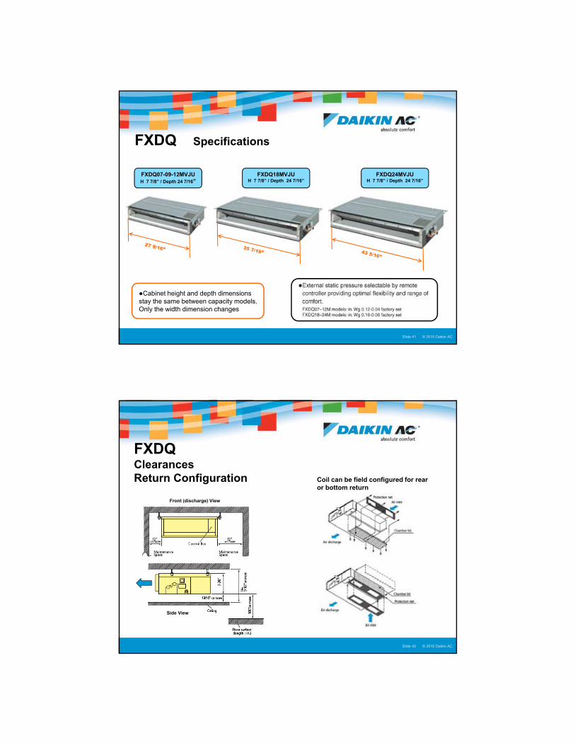
FXDQ Specifications
FXDQ07-09-12MVJUH 7 7/8” / Depth 24 7/16”
FXDQ18MVJUH 7 7/8” / Depth 24 7/16”
FXDQ24MVJUH 7 7/8” / Depth 24 7/16”
●Cabinet height and depth dimensions stay the same between capacity models. Only the width dimension changes
© 2005 Daikin ACSlide 42Presentation Title : Presenter Name : Date © 2010 Daikin ACSlide 42
FXDQ Clearances Return Configuration
Front (discharge) View
Side View
Coil can be field configured for rear or bottom return
22
© 2005 Daikin ACSlide 43Presentation Title : Presenter Name : Date © 2010 Daikin ACSlide 43
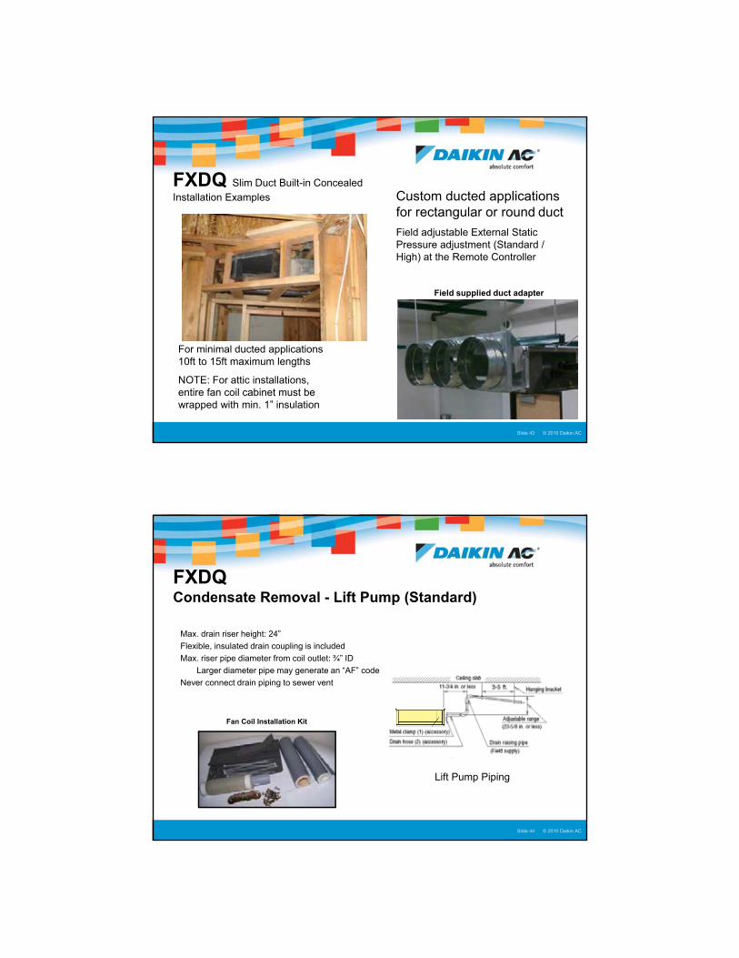
FXDQ Slim Duct Built-in Concealed
Installation Examples Custom ducted applications for rectangular or round duct
Field adjustable External Static Pressure adjustment (Standard / High) at the Remote Controller
For minimal ducted applications 10ft to 15ft maximum lengths
NOTE: For attic installations, entire fan coil cabinet must be wrapped with min. 1” insulation
Field supplied duct adapter
© 2005 Daikin ACSlide 44Presentation Title : Presenter Name : Date © 2010 Daikin ACSlide 44
FXDQ Condensate Removal - Lift Pump (Standard)
Fan Coil Installation Kit
Lift Pump Piping
� Max. drain riser height: 24”
� Flexible, insulated drain coupling is included
� Max. riser pipe diameter from coil outlet: ¾” ID
� Larger diameter pipe may generate an “AF” code
� Never connect drain piping to sewer vent

23
© 2005 Daikin ACSlide 45Presentation Title : Presenter Name : Date © 2010 Daikin ACSlide 45
�Gravity Condensate Conversion � Unplug Lift Pump connector at PCB X25A
� Remove coil drain plug and connect to drain piping
�Field supplied condensate drain pipe� Use flexible drain connector (Accessory)
� Must not contain any traps or kinks in the line
� Must maintain an even slope of 1/100 or greater
> 1/100*
No Trap
FXDQ Condensate Removal - Gravity
X25A
Drain Plug
© 2005 Daikin ACSlide 46Presentation Title : Presenter Name : Date © 2010 Daikin ACSlide 46
FXDQ Line voltage and Control Voltage

24
© 2005 Daikin ACSlide 47Presentation Title : Presenter Name : Date © 2010 Daikin ACSlide 47
FXMQ_PVJUDC Ducted Concealed
Models from 7 MBtu to 48 MBtu (FXMQ07- 48P) � Improved efficiency with our new DC (ECM) fan motor� Medium ESP capabilities of up to 1” W.G
� “Auto” adjust or select SP range from Remote Controller� 3 user select fan speeds available + Fan “Auto” Logic� Low profile design – less than 12” high� Built in Condensate Lift pump for 28” rise� Field supplied filter box and filters � Optional Filters (MERV 8 & 13)� Mechanical service from below� Weight: 55 lb. 07,09,12 80 lb. 18,24,30 102 lb. 36&48
© 2005 Daikin ACSlide 48Presentation Title : Presenter Name : Date © 2010 Daikin ACSlide 48
� Install Fan Coil with all-thread bolts
� Install nut and washer above and below each angle bracket
� Min. 1” open clearance from top of Fan Coil to bottom of structure
� Min. 28” X 18” service access on side
FXMQ_PVJUInstallation
TOP

25
© 2005 Daikin ACSlide 49Presentation Title : Presenter Name : Date © 2010 Daikin ACSlide 49
� Install Fan Coil with all-thread bolts
� Install nut and washer above and below each angle bracket
� Min. 1” open clearance from top of Fan Coil to bottom of structure
� Field supplied Supply Plenum
FXMQ_PVJUInstallation Side View
Front (discharge) View
© 2005 Daikin ACSlide 50Presentation Title : Presenter Name : Date © 2010 Daikin ACSlide 50
� Max. drain riser height: 28”
� Flexible, insulated drain coupling is included
� Max. riser pipe diameter from coil outlet: ¾” ID
� Larger diameter pipe may generate an “AF” code
� Never connect drain piping to sewer vent
� Properly support the horizontal piping to eliminate piping deflection
FXMQ_P Condensate Removal - Lift Pump (Standard)
Fan Coil Installation Kit
Lift Pump Piping

26
© 2005 Daikin ACSlide 51Presentation Title : Presenter Name : Date © 2010 Daikin ACSlide 51
�Gravity Condensate Conversion � Unplug Lift Pump connector at PCB (A1P) X25A
� Remove coil drain plug and connect to drain piping
�Field supplied condensate drain pipe� Use flexible drain connector (Accessory)
� Must not contain any traps or kinks in the line
� Must maintain an even slope of 1/100 or greater
> 1/100*
No Trap
FXMQ_P Condensate Removal - Gravity
X25A
Drain Plug
PCB “A1P”
© 2005 Daikin ACSlide 52Presentation Title : Presenter Name : Date © 2010 Daikin ACSlide 52
FXMQ_PVJULine Voltage and Control Voltage
27
© 2005 Daikin ACSlide 53Presentation Title : Presenter Name : Date © 2010 Daikin ACSlide 53
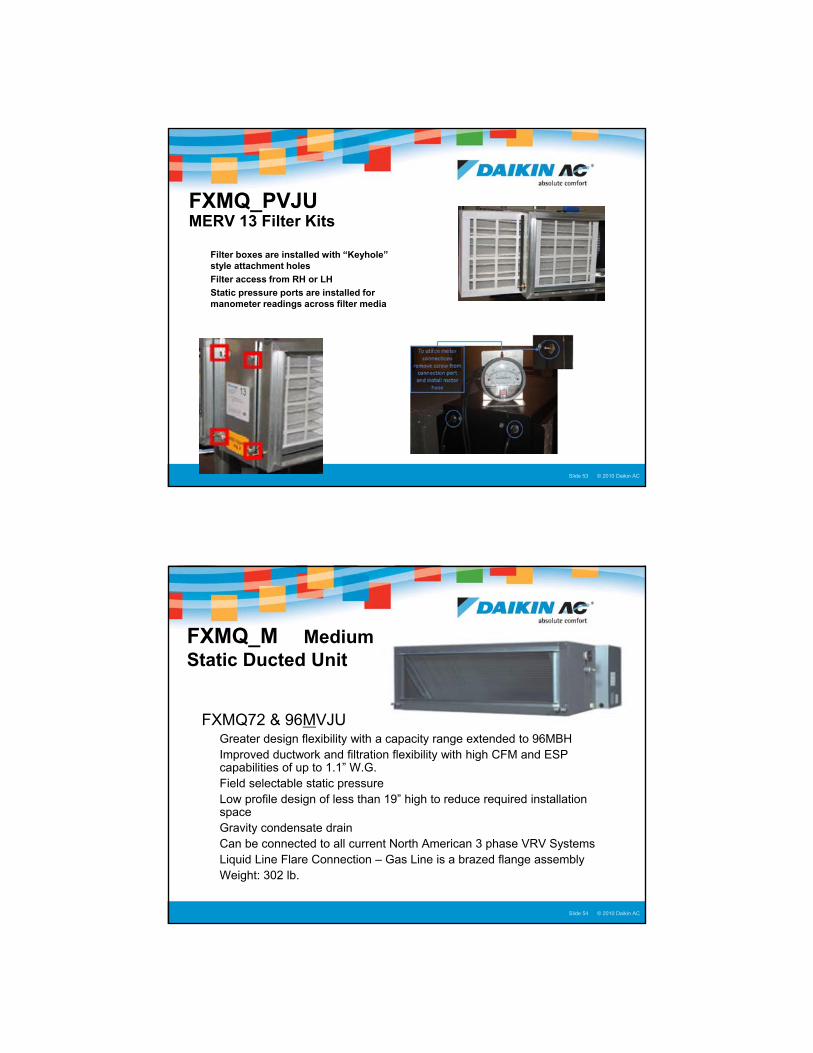
FXMQ_PVJUMERV 13 Filter Kits
� Filter boxes are installed with “Keyhole” style attachment holes
� Filter access from RH or LH
� Static pressure ports are installed for manometer readings across filter media
© 2005 Daikin ACSlide 54Presentation Title : Presenter Name : Date © 2010 Daikin ACSlide 54
FXMQ_M Medium Static Ducted Unit
�FXMQ72 & 96MVJU � Greater design flexibility with a capacity range extended to 96MBH� Improved ductwork and filtration flexibility with high CFM and ESP
capabilities of up to 1.1” W.G.� Field selectable static pressure� Low profile design of less than 19” high to reduce required installation
space� Gravity condensate drain� Can be connected to all current North American 3 phase VRV Systems� Liquid Line Flare Connection – Gas Line is a brazed flange assembly� Weight: 302 lb.

28
© 2005 Daikin ACSlide 55Presentation Title : Presenter Name : Date © 2010 Daikin ACSlide 55
� Install Fan Coil with all-thread bolts
� Install nut and washer above and below each angle bracket
� Min. 1” open clearance from top of Fan Coil to bottom of structure
� Field supplied Supply Plenum
FXMQ_MVJUInstallation
Side View
Front (discharge) View
© 2005 Daikin ACSlide 56Presentation Title : Presenter Name : Date © 2010 Daikin ACSlide 56
� A field supplied condensate pump must be used when gravity condensate removal is not possible
� Pump must be properly sized for the specific application
� Locate the X8A jumper on the FXMQ PCB and splice in the pump float switch wires
FXMQ_MVJUCondensate Pump
X 8 A

29
© 2005 Daikin ACSlide 57Presentation Title : Presenter Name : Date © 2010 Daikin ACSlide 57
FXMQ_MVJUDimensions and Clearances
Top View
Capacity Model MBtu
72 96
Height 18 1/8” 18 1/8”
Depth 43 5/16” 43 5/16”
Width 54 3/8” 54 3/8”
© 2005 Daikin ACSlide 58Presentation Title : Presenter Name : Date © 2010 Daikin ACSlide 58
FXTQ_PAVJUVertical Air Handler
� Offered in 8 model sizes from 12 MBTU's to 54 MBTU's
� Integrated EEV, PCB & Other Components
� Upflow and Horizontal Right configuration
� 208-230V/1/60Hz Power Supply
� Brazed Pipe Connections (1/4”x1/2” and 3/8”x5/8”)
� Hi & Low Fan Speeds + Fan “AUTO” Logic
� ECM Blower Motor
� ESP automatically set based on installed ductwork (Max. 0.5” WG)
� Slide-in Electric Heater Options - 3kW to 20 kW
� NOTE: System Pressure Test to 450 psi only
30
© 2005 Daikin ACSlide 59Presentation Title : Presenter Name : Date © 2010 Daikin ACSlide 59
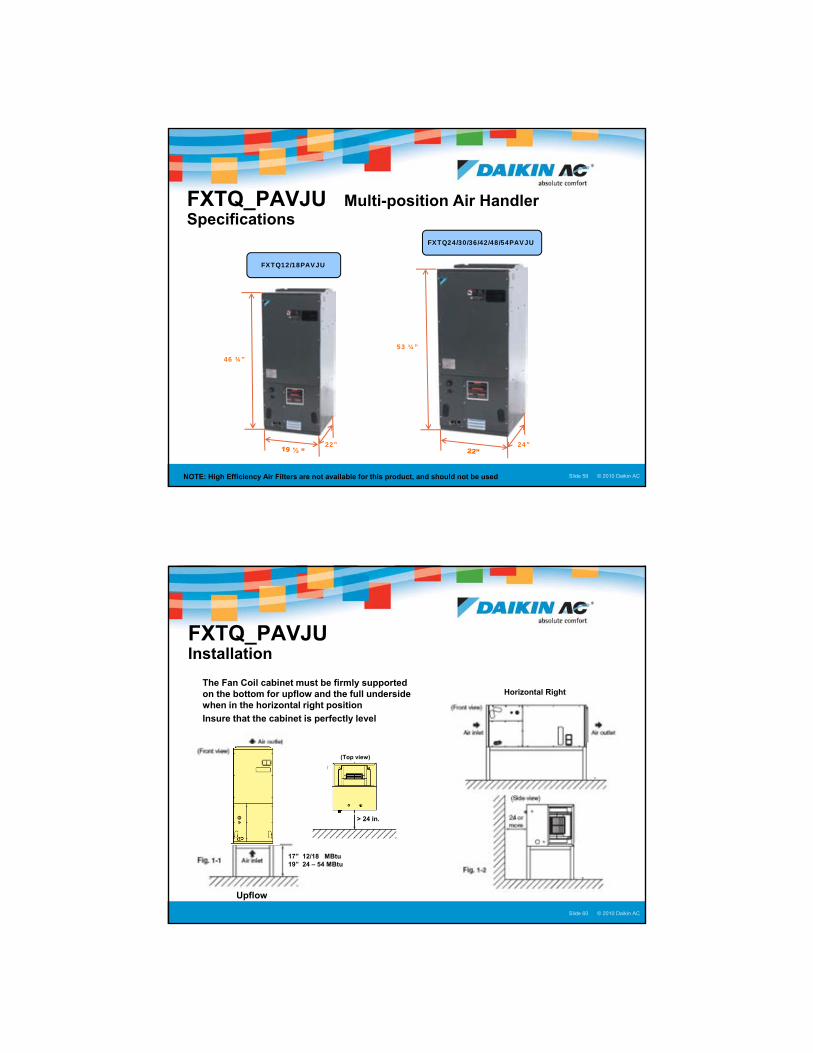
FXTQ_PAVJU Multi-position Air Handler Specifications
46 ¾”
22”
53 ¼”
24”
FXTQ12/18PAVJU
FXTQ24/30/36/42/48/54PAVJU
NOTE: High Efficiency Air Filters are not available for this product, and should not be used
© 2005 Daikin ACSlide 60Presentation Title : Presenter Name : Date © 2010 Daikin ACSlide 60
FXTQ_PAVJUInstallation
� The Fan Coil cabinet must be firmly supported on the bottom for upflow and the full underside when in the horizontal right position
� Insure that the cabinet is perfectly level
Upflow
17” 12/18 MBtu 19” 24 – 54 MBtu
Horizontal Right
> 24 in.
(Top view)

31
© 2005 Daikin ACSlide 61Presentation Title : Presenter Name : Date © 2010 Daikin ACSlide 61
� Fan Coil requires a “P Trap” for the condensate drain
� Copper type W, or sched’l 40 PVC tubing may be used for the condensate drain
� Provision should be made to clean the trap
FXTQ_PAVJUCondensate Installation
Upflow PositionHorizontal Right Position
© 2005 Daikin ACSlide 62Presentation Title : Presenter Name : Date © 2010 Daikin ACSlide 62
� PCB’s, Line voltage and Control voltage connections
� Control transformer set for 240 vac
� For 208 vac power supply change transformer primary tap
Line Voltage Control Voltage
FXTQ_PAVJU Line & Control circuits

32
© 2005 Daikin ACSlide 63Presentation Title : Presenter Name : Date © 2010 Daikin ACSlide 63
FXTQ_PAVJU Temperature Control
� The FXTQ-PAVJU is not equipped with a return air sensor.
Temperature Control Options:� BRC1E71 Remote Controller
� BRC2A71 Simplified with
KRCS01-4B Remote Sensor
� KRCS01-4B Sensor Only
BRC1E71 BRC2A71 Simplified
Remote Sensor Only
NEW - KRCS01-4B Remote Sensor is required
Sensor in controller
NOTE: BRC1E71 is factory default – Field setting change is required for Remote Sensor Applications
© 2005 Daikin ACSlide 64Presentation Title : Presenter Name : Date © 2010 Daikin ACSlide 64
� KRCS01-4B Remote Sensor Connection� Control application using Simplified RC or no RC� Any application using the Remote Sensor requires a field
setting change at the Remote Controller [10(20) 2-02] “C9” or “CJ” fault code if field setting is not changed
X16A Remote Sensor Cable Connection
FXTQ_PAVJU Remote Sensor Application
KRCS01-4B Remote Sensor
NOTE: Remote Sensor Cable uses a 4 pin (2-wire) connector at X16A
33
© 2005 Daikin ACSlide 65Presentation Title : Presenter Name : Date © 2010 Daikin ACSlide 65
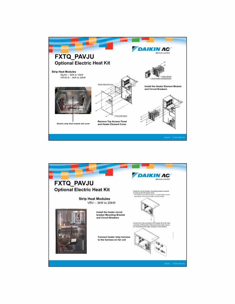
FXTQ_PAVJU Optional Electric Heat Kit
Strip Heat Modules� SkyAir – 3kW to 10kW� VRVIII-S – 3kW to 20kW
Remove Top Access Panel and Heater Element Cover
Install the Heater Element Module and Circuit Breakers
Electric strip heat module slot cover
© 2005 Daikin ACSlide 66Presentation Title : Presenter Name : Date © 2010 Daikin ACSlide 66
FXTQ_PAVJU Optional Electric Heat Kit
Strip Heat Modules� VRV – 3kW to 20kW
Install the heater circuit breaker Mounting Bracket and Circuit Breakers
Connect heater relay harness to the harness on fan coil

34
© 2005 Daikin ACSlide 67Presentation Title : Presenter Name : Date © 2010 Daikin ACSlide 67
FXTQ_PAVJU Optional Electric Heat Kit
� Install the line voltage wiring into top of cabinet
� Remove the breaker knockout cover on front panel
� Install Front Panel
� Field setting at remote controller is required
© 2005 Daikin ACSlide 68Presentation Title : Presenter Name : Date © 2010 Daikin ACSlide 68
FXTQ_PAVJU Optional Humidifier and Air Purifier
� Field supplied accessories can be controlled
� Run the wires through the low voltage hole
� Connect the device control wires on Terminal Block 10P
� Field setting at remote controller is required for fan control

35
© 2005 Daikin ACSlide 69Presentation Title : Presenter Name : Date © 2010 Daikin ACSlide 69
FXTQ_PAVJU Humidifier Interlock
�New control logic has been added to improve humidifier integration� No additional control board is required
�Switches the indoor unit fan to high fan speed when the humidifier on signal is received� Terminals 7-8, dry contact
�The fan residual run on timer can be programmed on site from 30-120 seconds � Helps remove excess moisture from
ductwork
© 2005 Daikin ACSlide 70Presentation Title : Presenter Name : Date © 2010 Daikin ACSlide 70
�FXAQ (7/9/12/18/24)MVJU – (7,000 to 24,000 Btu/h)
Wall Mounted� Very low sound levels� Auto-swing feature ensures efficient air distribution� Louvers automatically close when unit is turned off� Wide air discharge outlet distributes a comfortable airflow through the entire
space� Flexible routing of refrigerant and condensate lines
Options Include:� Condensate Pump� Controls
VRV Duct-free Units
36
© 2005 Daikin ACSlide 71Presentation Title : Presenter Name : Date © 2010 Daikin ACSlide 71
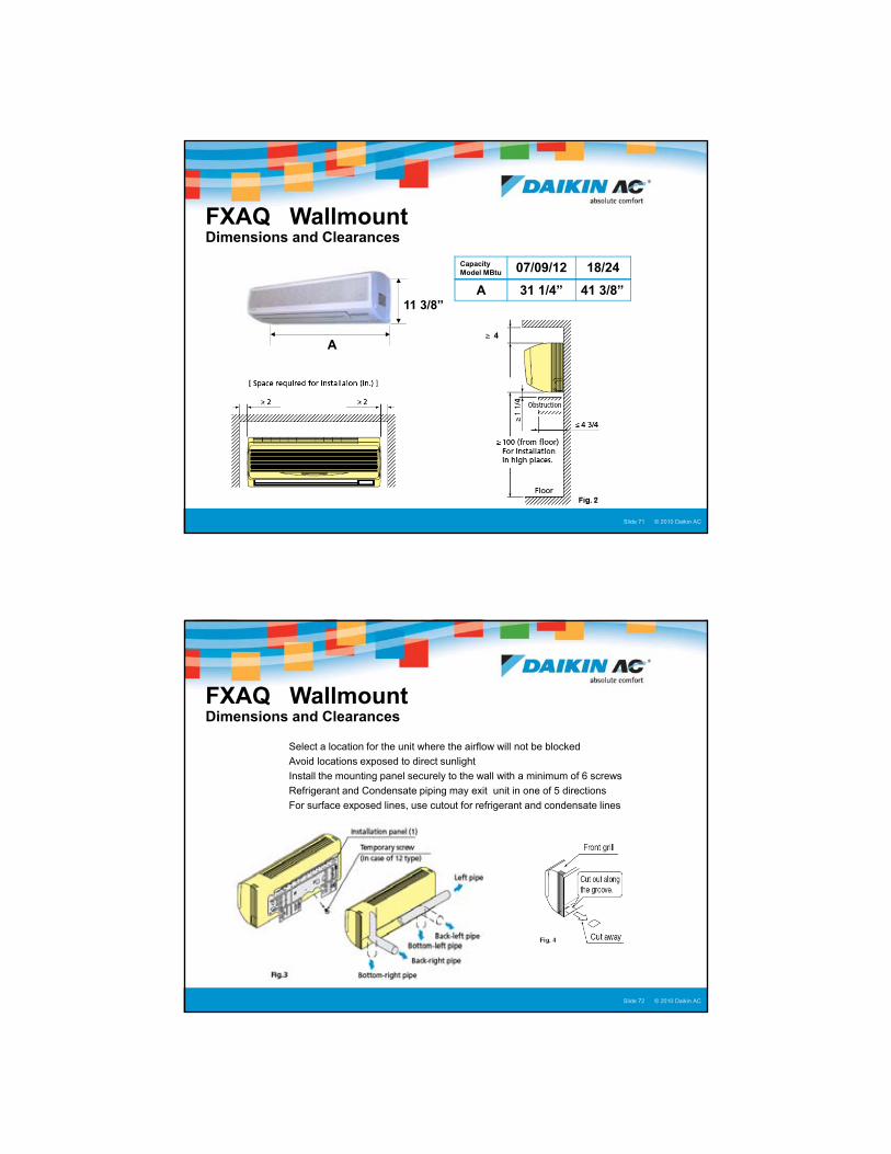
A
11 3/8”
FXAQ Wallmount Dimensions and Clearances
Capacity Model MBtu 07/09/12 18/24
A 31 1/4” 41 3/8”
4
© 2005 Daikin ACSlide 72Presentation Title : Presenter Name : Date © 2010 Daikin ACSlide 72
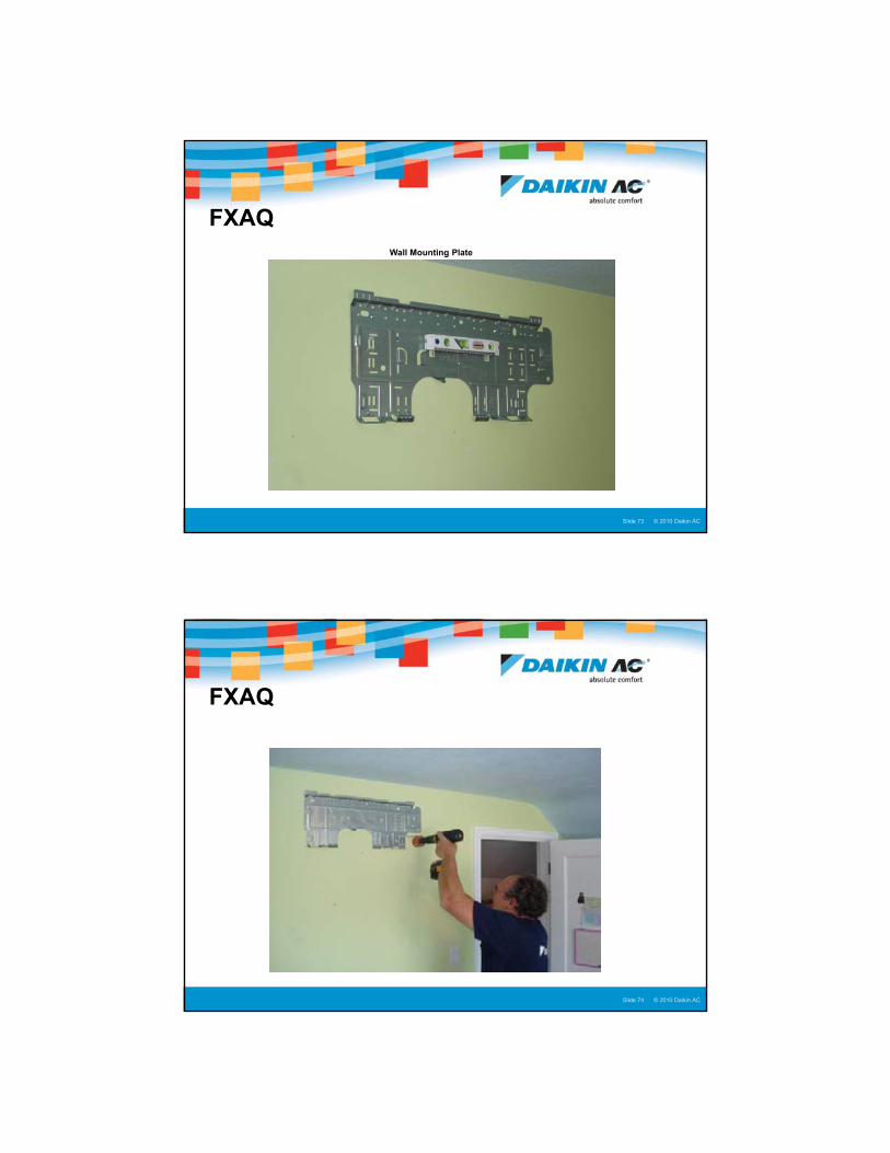
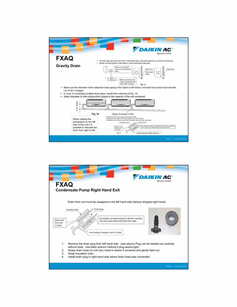
� Select a location for the unit where the airflow will not be blocked
� Avoid locations exposed to direct sunlight
� Install the mounting panel securely to the wall with a minimum of 6 screws
� Refrigerant and Condensate piping may exit unit in one of 5 directions
� For surface exposed lines, use cutout for refrigerant and condensate lines
FXAQ Wallmount Dimensions and Clearances
37
© 2005 Daikin ACSlide 73Presentation Title : Presenter Name : Date © 2010 Daikin ACSlide 73
FXAQ Wall Mounting Plate
© 2005 Daikin ACSlide 74Presentation Title : Presenter Name : Date © 2010 Daikin ACSlide 74
FXAQ

38
© 2005 Daikin ACSlide 75Presentation Title : Presenter Name : Date © 2010 Daikin ACSlide 75
�Installing refrigerant and drain pipe through exterior wall� For walls containing metal frame or siding, use field supplied conduit or
grommet to prevent heat transfer, electrical shock or fire� Fill all gaps around the piping with caulk or putty to prevent water leaks� Drill or cut a 3 1/8” diameter hole� Insure that the hole has a slight down angle from the inside to the outside
FXAQ
© 2005 Daikin ACSlide 76Presentation Title : Presenter Name : Date © 2010 Daikin ACSlide 76
FXAQRear of Wall Mount Unit - Right hand exit

39
© 2005 Daikin ACSlide 77Presentation Title : Presenter Name : Date © 2010 Daikin ACSlide 77
Rear of Wall Mount Unit - Left hand exit
FXAQ
© 2005 Daikin ACSlide 78Presentation Title : Presenter Name : Date © 2010 Daikin ACSlide 78
When making the penetration on the left side of the unit tuck the line set in the back of unit and wrap with felt tape.
Secure the indoor unit to the installation panel with the securing screws.
FXAQ
40
© 2005 Daikin ACSlide 79Presentation Title : Presenter Name : Date © 2010 Daikin ACSlide 79
Insert using an Allen wrench.
When making the penetration on the left side of the unit it is possible to relocate the drain from right to left.
FXAQGravity Drain
© 2005 Daikin ACSlide 80Presentation Title : Presenter Name : Date © 2010 Daikin ACSlide 80
Drain from unit must be swapped to the left hand side (factory shipped right hand).
1. Remove the drain plug from left hand side. (see above) Plug can be twisted out carefully without tools. Use Allen wrench method if plug seems tight.
2. Grasp drain hose on unit very close to where it connects and gently twist out.3. Swap Insulation tube.4. Install drain plug in right hand side where drain hose was connected.
Drain Plug
Insulation Tube
FXAQ Condensate Pump Right Hand Exit

41
© 2005 Daikin ACSlide 81Presentation Title : Presenter Name : Date © 2010 Daikin ACSlide 81
Vent Hose
Complete Drain & Pump Assembly
Drain hose and fitting should be installed on Indoor Unit first.
FXAQ Condensate Pump Right Hand Exit
© 2005 Daikin ACSlide 82Presentation Title : Presenter Name : Date © 2010 Daikin ACSlide 82Right Hand Exit View from Back
Setting Up Hose Connections For Right Hand Exit
FXAQ Condensate Pump

42
© 2005 Daikin ACSlide 83Presentation Title : Presenter Name : Date © 2010 Daikin ACSlide 83
Hold back insulation and push corrugated tubing into fitting.After it bottoms out slide insulation back towards fitting.
Setting Up Hose Connections For Right Hand Exit
FXAQ Condensate Pump Right Hand Exit
© 2005 Daikin ACSlide 84Presentation Title : Presenter Name : Date © 2010 Daikin ACSlide 84
Very, very tight when Installed with line set!
Using the left hand exit gives you very little room for the pump and float assembly
FXAQ Condensate Pump Left Hand Exit

43
© 2005 Daikin ACSlide 85Presentation Title : Presenter Name : Date © 2010 Daikin ACSlide 85
Cut tubing as you assemble pump, line set and drain
assembly
Pump outlet connection. Run to main drain of
building or equivalent.
Verify lubing lengths before cutting, Lengths may vary depending on installation.
Setting Up Hose Connections For Left Hand Exit
FXAQ Optional Condensate Pump Kit
© 2005 Daikin ACSlide 86Presentation Title : Presenter Name : Date © 2010 Daikin ACSlide 86
VRV DIII-NetAlternate Condensate Safety
X15A Jumper
FXHQ
X15A Circuit interruption disables fan coil and generates an “A3” code
Splice in optional condensate pump float switch leads to jumper using crimp butt connectors or solder
FXAQ
FXLQ/FXNQ
Alternate float switch connection from T1 T2 Forced Off to PCB jumper X15A or X8A . Interruption of safety through jumper disables operation of connected fan coil only, remaining fan coils continue full cool operation. Outdoor unit operation is not affected. X8A Circuit interruption disables fan coil
and generates an “A3” code
X8A Jumper
X8A

44
© 2005 Daikin ACSlide 87Presentation Title : Presenter Name : Date © 2010 Daikin ACSlide 87
Don’t forget to prime pump! The pump will buzz for a minute of two while it is pulling the water through itself.
Priming PumpFXAQ
© 2005 Daikin ACSlide 88Presentation Title : Presenter Name : Date © 2010 Daikin ACSlide 88
Wiring ConnectionsFXAQ
45
© 2005 Daikin ACSlide 89Presentation Title : Presenter Name : Date © 2010 Daikin ACSlide 89
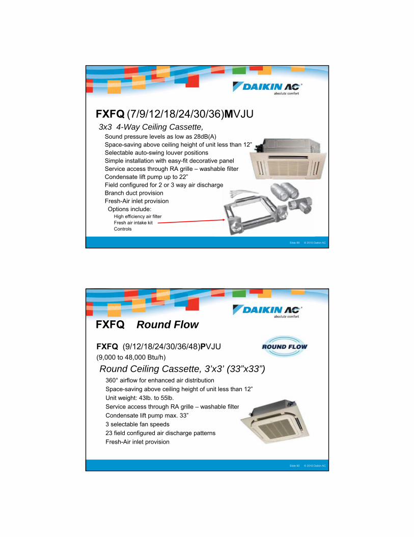
�FXFQ (7/9/12/18/24/30/36)MVJU3x3 4-Way Ceiling Cassette, � Sound pressure levels as low as 28dB(A)� Space-saving above ceiling height of unit less than 12”� Selectable auto-swing louver positions� Simple installation with easy-fit decorative panel� Service access through RA grille – washable filter� Condensate lift pump up to 22”� Field configured for 2 or 3 way air discharge� Branch duct provision� Fresh-Air inlet provision
Options include:� High efficiency air filter� Fresh air intake kit� Controls
© 2005 Daikin ACSlide 90Presentation Title : Presenter Name : Date © 2010 Daikin ACSlide 90
FXFQ Round Flow
�FXFQ (9/12/18/24/30/36/48)PVJU (9,000 to 48,000 Btu/h)
Round Ceiling Cassette, 3’x3’ (33”x33”)� 360° airflow for enhanced air distribution
� Space-saving above ceiling height of unit less than 12”
� Unit weight: 43lb. to 55lb.
� Service access through RA grille – washable filter
� Condensate lift pump max. 33”
� 3 selectable fan speeds
� 23 field configured air discharge patterns
� Fresh-Air inlet provision
46
© 2005 Daikin ACSlide 91Presentation Title : Presenter Name : Date © 2010 Daikin ACSlide 91
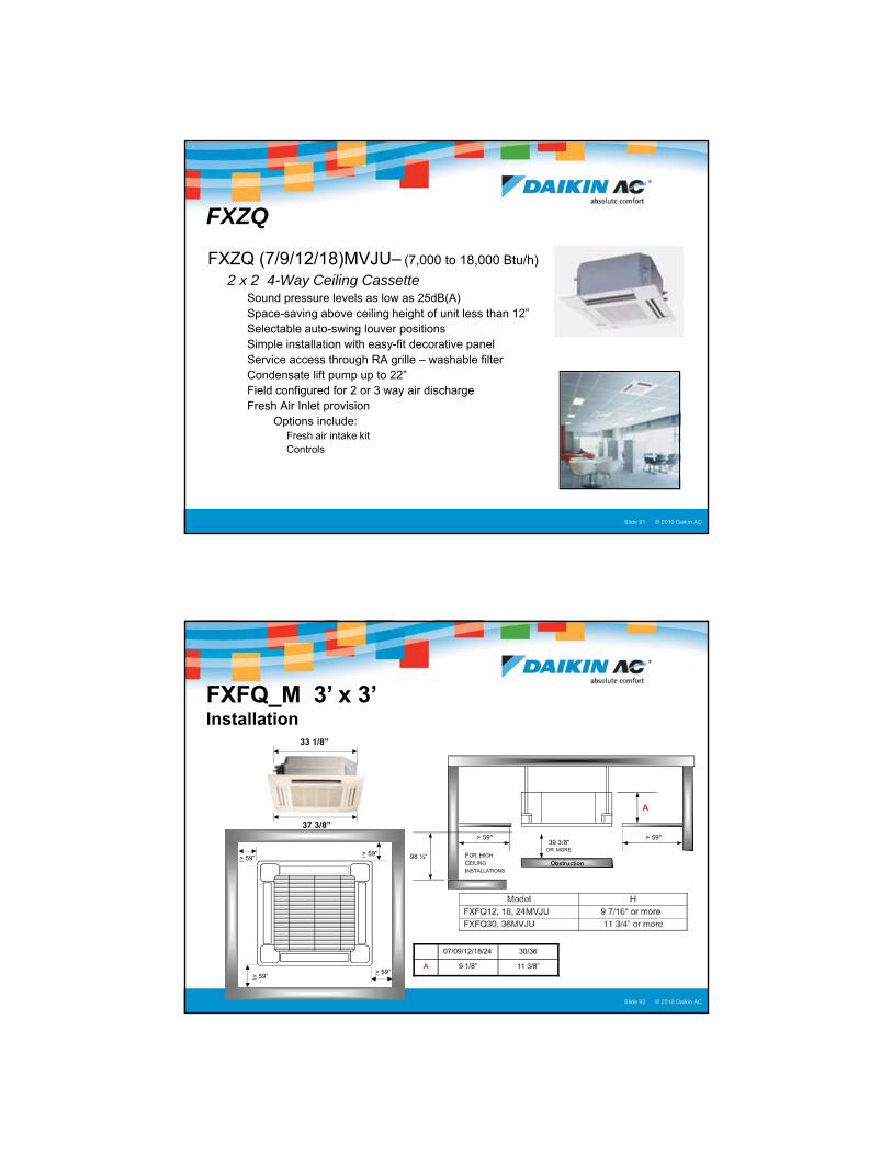
FXZQ
�FXZQ (7/9/12/18)MVJU– (7,000 to 18,000 Btu/h)
�2 x 2 4-Way Ceiling Cassette� Sound pressure levels as low as 25dB(A)� Space-saving above ceiling height of unit less than 12”� Selectable auto-swing louver positions� Simple installation with easy-fit decorative panel� Service access through RA grille – washable filter� Condensate lift pump up to 22”� Field configured for 2 or 3 way air discharge� Fresh Air Inlet provision
Options include:� Fresh air intake kit� Controls
© 2005 Daikin ACSlide 92Presentation Title : Presenter Name : Date © 2010 Daikin ACSlide 92
37 3/8”
33 1/8”
07/09/12/18/24 30/36
A 9 1/8” 11 3/8”> 59”
> 59”
> 59”
> 59” FOR HIGH
CEILING
INSTALLATIONS
98 ½”
> 59" > 59"39 3/8"
OR MORE
A
FXFQ_M 3’ x 3’ Installation
Obstruction

47
© 2005 Daikin ACSlide 93Presentation Title : Presenter Name : Date © 2010 Daikin ACSlide 93
FXFQ Installation
© 2005 Daikin ACSlide 94Presentation Title : Presenter Name : Date © 2010 Daikin ACSlide 94
FXFQ_P Installation
� Max. drain riser height: 33 1/2”
� Flexible, insulated drain coupling is included
� Max. riser pipe diameter from coil outlet: ¾” ID
� Larger diameter pipe may generate an “AF” code
� Never connect drain piping to sewer vent

48
© 2005 Daikin ACSlide 95Presentation Title : Presenter Name : Date © 2010 Daikin ACSlide 95
FXFQ Installation
© 2005 Daikin ACSlide 96Presentation Title : Presenter Name : Date © 2010 Daikin ACSlide 96
FXFQ/FXZQ Electrical Installation
FXZQ
FXFQ
49
© 2005 Daikin ACSlide 97Presentation Title : Presenter Name : Date © 2010 Daikin ACSlide 97
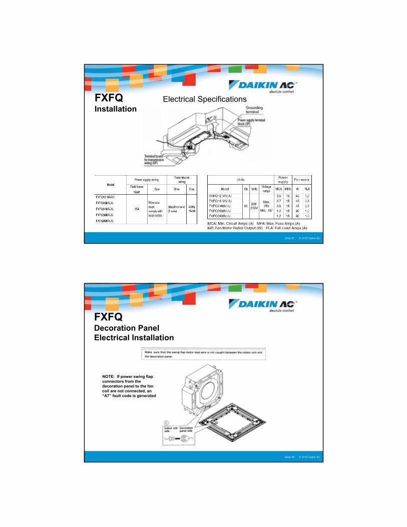
Electrical SpecificationsFXFQ Installation
© 2005 Daikin ACSlide 98Presentation Title : Presenter Name : Date © 2010 Daikin ACSlide 98
FXFQ Decoration Panel Electrical Installation
NOTE: If power swing flap connectors from the decoration panel to the fan coil are not connected, an “A7” fault code is generated

50
© 2005 Daikin ACSlide 99Presentation Title : Presenter Name : Date © 2010 Daikin ACSlide 99
Adjustment ScrewMounting loop
FXFQ Decoration Panel Installation
Mounting tab
© 2005 Daikin ACSlide 100Presentation Title : Presenter Name : Date © 2010 Daikin ACSlide 100
FXFQ Face Plate Installation

51
© 2005 Daikin ACSlide 101Presentation Title : Presenter Name : Date © 2010 Daikin ACSlide 101
FXZQ 2’x2’ Ceiling Cassette
Decoration Panel Installation
Decoration Panel Mounting Straps Decoration Panel Swivel SupportMatch 2 screws to elongated holes on panel
� Install 2 of the 4 supplied mounting screws into the designated fan coil mounting straps
� Install the elongated mounting holes of the decoration panel onto these 2 screws to hold panel in place
� Rotate the swivel support finger on the panel over the tab on the electrical enclosure to support panel
� Install remaining 2 screws and secure all 4
© 2005 Daikin ACSlide 102Presentation Title : Presenter Name : Date © 2010 Daikin ACSlide 102
FXHQ�FXHQ (12/24/36)MVJU – (12,000 to 36,000 Btu/h)
�Ceiling Suspended� Slim design – less than 8” high
� Wide air discharge outlet distributes a comfortable airflow throughout the entire space
� Gravity condensate drain
� Standard equipped with a washable, long-life, mildew-proof filter
� Long Air Throw 15-20 ft
� Direct Fresh Air Possible
Options Include:� Condensate Pump
� Controls
52
© 2005 Daikin ACSlide 103Presentation Title : Presenter Name : Date © 2010 Daikin ACSlide 103
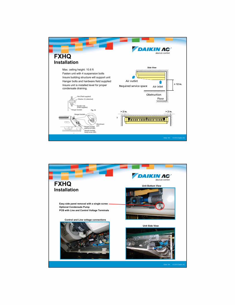
FXHQ Installation
� Max. ceiling height: 10.6 ft
� Fasten unit with 4 suspension bolts
� Insure building structure will support unit
� Hanger bolts and hardware field supplied
� Insure unit is installed level for proper condensate draining.
Front (discharge) View
> 12 in.
Side View
> 2 in. > 2 in.
© 2005 Daikin ACSlide 104Presentation Title : Presenter Name : Date © 2010 Daikin ACSlide 104
FXHQ Installation
� Easy side panel removal with a single screw
� Optional Condensate Pump
� PCB with Line and Control Voltage Terminals
Unit Bottom View
Unit Side View
Control and Line voltage connections

53
© 2005 Daikin ACSlide 105Presentation Title : Presenter Name : Date © 2010 Daikin ACSlide 105
� Refrigerant lines may be run through the top access
� Refrigerant and condensate lines may be run through right rear or side of unit.
Not UsedRefrigerant Lines & Drain through RH rear or side
FXHQ Refrigerant & Condensate Lines Refrigerant Lines through top RH
© 2005 Daikin ACSlide 106Presentation Title : Presenter Name : Date © 2010 Daikin ACSlide 106
�FXLQ (12/18/24)MVJU – (12,000 to 24,000 Btu/h)
�Floor Mounted, Exposed� Unit requires minimal installation space
� Standard equipped with a washable, long-life, mildew-proof filter
� Space-saving unit can be mounted freestanding or secured directly to the wall
� Gravity condensate drain
� Optional Condensate Pump
FXLQ

54
© 2005 Daikin ACSlide 107Presentation Title : Presenter Name : Date © 2010 Daikin ACSlide 107
�FXNQ (12/18/24)MVJU – (12,000 to 24,000 Btu/h)
�Floor Mounted, Concealed
�No panels for custom enclosure installation
�Unit requires minimal installation space
�Standard equipped with a washable, long-life, mildew-proof filter
Options Include:� Condensate Pump
� Controls
FXNQ
© 2005 Daikin ACSlide 108Presentation Title : Presenter Name : Date © 2010 Daikin ACSlide 108
FXLQ Remove and Replace Front Panel
� Open upper right and left access lids
� Remove the locking screw for each slide clip
� Loosen front slide clip screw – RH LH
� Move both right and left slide clips toward rear
� Lift the top grille panel
� Remove front panel – top forward
� Reverse procedure
Remove this screw
Front panel release slide clip
Loosen this screw 1/8 turn
Top LH View

55
© 2005 Daikin ACSlide 109Presentation Title : Presenter Name : Date © 2010 Daikin ACSlide 109
FXLQ/FXNQ
© 2005 Daikin ACSlide 110Presentation Title : Presenter Name : Date © 2010 Daikin ACSlide 110
8 3/4”
23 5/8”
A
12 18 24
A 44 7/8” 55 7/8” 55 7/8”
3/4” or more
4” or More
40" or more
Air In
Air Out
70 " or more
Floor Mounted Clearances
4” or More
FXLQ/FXNQ
56
© 2005 Daikin ACSlide 111Presentation Title : Presenter Name : Date © 2010 Daikin ACSlide 111
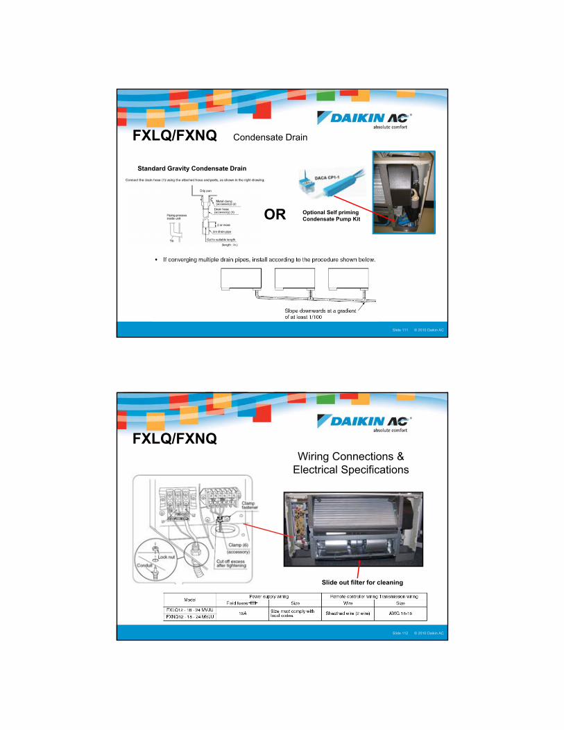
FXLQ/FXNQ Condensate Drain
Standard Gravity Condensate Drain
OR Optional Self priming Condensate Pump Kit
© 2005 Daikin ACSlide 112Presentation Title : Presenter Name : Date © 2010 Daikin ACSlide 112
Wiring Connections & Electrical Specifications
FXLQ/FXNQ
Slide out filter for cleaning

57
© 2005 Daikin ACSlide 113Presentation Title : Presenter Name : Date © 2010 Daikin ACSlide 113
VRV 100% OA Processing Unit
�FXMQ (48/72/96)MFVJU� 4, 6 & 8 Ton capacity models
� ESP Max. 1.03” w.g.
Compatible with all VRV systems
© 2005 Daikin ACSlide 114Presentation Title : Presenter Name : Date © 2010 Daikin ACSlide 114
FXMQ_MFVJU Dimensions and Clearances
Top View
Capacity Model MBtu
48 72/96
Height 18 ½” 18 ½”
Depth 43 ½” 43 ½”
Width 29 ¼” 54 3/8”

58
© 2005 Daikin ACSlide 115Presentation Title : Presenter Name : Date © 2010 Daikin ACSlide 115
� Line and Control circuits
� Line voltage to X1M
� Control voltage to X2M
FXMQ_MFVJU Electrical
© 2005 Daikin ACSlide 116Presentation Title : Presenter Name : Date © 2010 Daikin ACSlide 116
� Unit is controlled by a programmed Field Setting for Heat and Cool discharge air temperature
FXMQ_MFVJU Control
59
© 2005 Daikin ACSlide 117Presentation Title : Presenter Name : Date © 2010 Daikin ACSlide 117
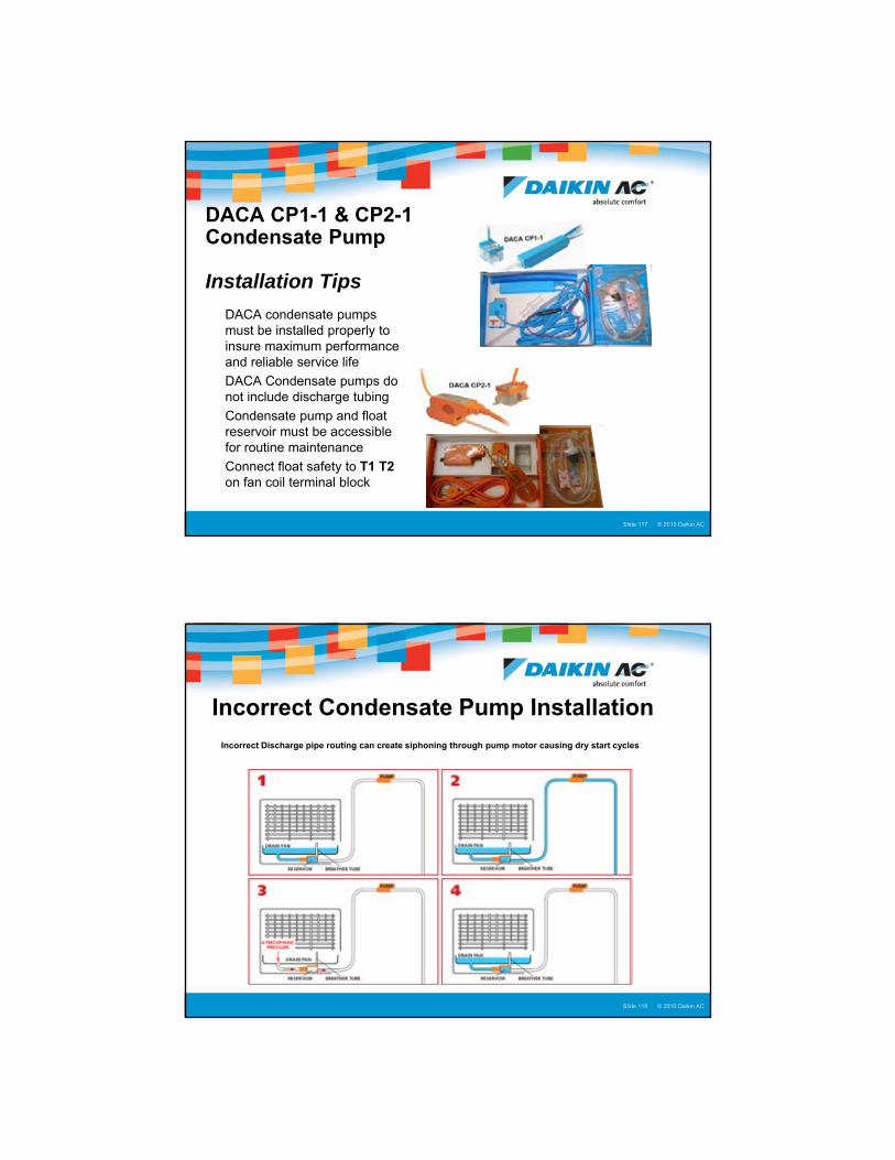
DACA CP1-1 & CP2-1Condensate Pump
Installation Tips
� DACA condensate pumps must be installed properly to insure maximum performance and reliable service life
� DACA Condensate pumps do not include discharge tubing
� Condensate pump and float reservoir must be accessible for routine maintenance
� Connect float safety to T1 T2 on fan coil terminal block
© 2005 Daikin ACSlide 118Presentation Title : Presenter Name : Date © 2010 Daikin ACSlide 118
Incorrect Condensate Pump Installation
Incorrect Discharge pipe routing can create siphoning through pump motor causing dry start cycles
60
© 2005 Daikin ACSlide 119Presentation Title : Presenter Name : Date © 2010 Daikin ACSlide 119
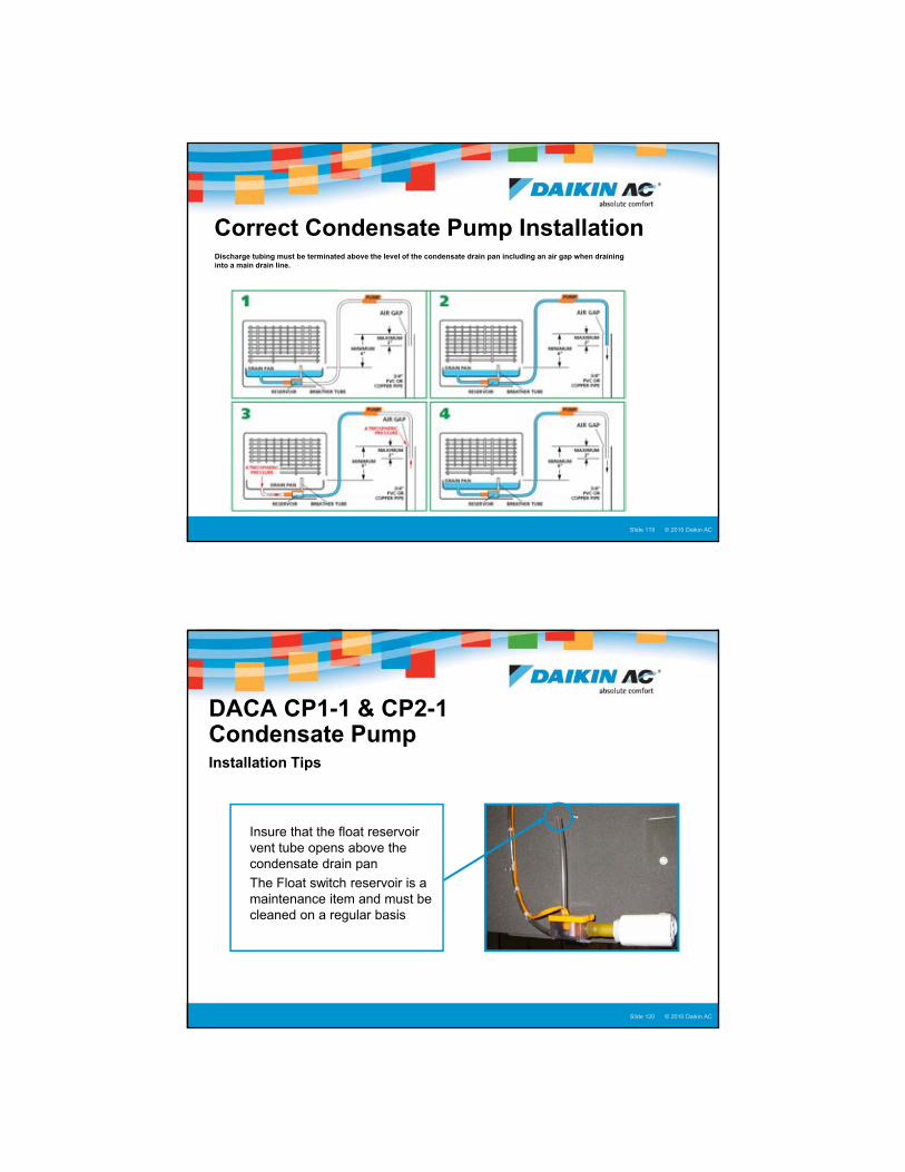
Correct Condensate Pump InstallationDischarge tubing must be terminated above the level of the condensate drain pan including an air gap when draining into a main drain line.
© 2005 Daikin ACSlide 120Presentation Title : Presenter Name : Date © 2010 Daikin ACSlide 120
� Insure that the float reservoir vent tube opens above the condensate drain pan
� The Float switch reservoir is a maintenance item and must be cleaned on a regular basis
DACA CP1-1 & CP2-1Condensate Pump Installation Tips

61
© 2005 Daikin ACSlide 121Presentation Title : Presenter Name : Date © 2010 Daikin ACSlide 121
VRVIII & VRV-WIIIBSVQ_PVJU Single Port Branch Selector Box
� 36, 60 & 96 capacity models
� Line voltage powered 208/230vac 1 Ph.
� Weight: 36/60: 26 lb. 96: 33 lb.
� Refrigerant Braze Connections
� BS Box must be installed level
© 2005 Daikin ACSlide 122Presentation Title : Presenter Name : Date © 2010 Daikin ACSlide 122
VRVIII & VRV-WIIIBSVQ_PVJU Branch Selector Box
� Branch Selector Box must be installed level
� Control circuit is daisy chain wired
� Field Reversible Electrical Box
� Green status LED
NOTE: All Expansion Valves close when power Is applied to the BS Box
Do Not change DIP switch settings

62
© 2005 Daikin ACSlide 123Presentation Title : Presenter Name : Date © 2010 Daikin ACSlide 123
BSV4/6Q36PVJUCentralized 4-Port & 6-Port Branch Selector Box
BSV4Q36PVJU 4 - Port
BSV6Q36PVJU 6 - Port
� BS box must be installed level
� Install unit with suspension bolts
� Line voltage powered 208/230vac 1 Ph.� MCA: .4/.6 amp
� BS Box shipped with all EEV’s in open position� All EEV’s close when line voltage power is applied
� All braze refrigerant connections
� “Closed Pipe Kit” is available for 1 unused port
� No condensate drain is required
© 2005 Daikin ACSlide 124Presentation Title : Presenter Name : Date © 2010 Daikin ACSlide 124
BSV4/6Q36PVJUInstallation
� Install the Centralized BS box right side up only and level
� Allow for proper service clearances� Suspend with 3/8” or 5/16” Suspension bolts
� Secure bolts with nut and washer above and below each angle bracket
� Allow a minimum of 10” clearance above BS box
� Refer to Installation Manual for all clearances
� Support refrigerant lines within 40” or less of BS box
> 10”

63
© 2005 Daikin ACSlide 125Presentation Title : Presenter Name : Date © 2010 Daikin ACSlide 125
BSV4/6Q36PVJUInstallation
Optional KHFP26A100C “Closed Pipe Kit”
© 2005 Daikin ACSlide 126Presentation Title : Presenter Name : Date © 2010 Daikin ACSlide 126
BSV4/6Q36PVJUInstallation – Control Wiring
Centralized Branch Selector Box
� Standard Daikin control wire specification
64
© 2010 Daikin AC
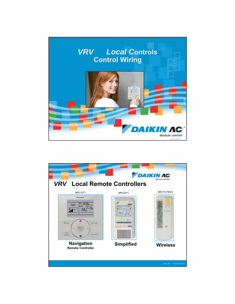
VRV Local ControlsControl Wiring
© 2005 Daikin ACSlide 128Presentation Title : Presenter Name : Date © 2010 Daikin ACSlide 128
Simplified Wireless
VRV Local Remote ControllersBRC2A71 BRC7C/7E/4C
NavigationRemote Controller
BRC1E71

65
© 2005 Daikin ACSlide 129Presentation Title : Presenter Name : Date © 2010 Daikin ACSlide 129
KRCS01-1B (4B) Remote Sensor
� VRV Fan Coil Units incorporate a built-in return air thermistor temperature sensor as standard (excl. FXTQ)� KRCS01-1B Remote Sensor is offered to replace the return air thermistor when:
� Outside fresh air is brought in to the fan coil return air
� Ceiling height of fan coil return is 13ft or more
� Above ceiling plenum return is used
� Standard 39ft cable - Plenum Rated 40ft and 80ft cable optional (KRCS01-1B)
NOTE: KRCS01-4B Remote Sensor Kit for FXMQ_P and FTQ/FXTQ Fan Coil Units
© 2005 Daikin ACSlide 130Presentation Title : Presenter Name : Date © 2010 Daikin ACSlide 130
VRVControl Circuit Terminal Designations
� Fan Coil Control Terminal Circuits� P1 P2 – Fan Coil to Remote Controller
� Remote Controller power supply and data transfer
� F1 F2 – Condenser to Fan Coil Communications� T1 T2 – Forced Off (Default N.O.) External Contacts
� Branch Selector Box� F1 F2 Out – BS Boxes to Condenser F1 F2 In� F1 F2 In – BS Box to Fan Coil F1 F2
� Condenser Control Terminal Circuits� F1 F2 In - Condenser to Fan Coil(s) or BS Boxes� F1 F2 Out – Centralized Controller
� I-Touch� Gateway – Lon Works or BACnet
� Q1 Q2 – Manifolded Modules
All VRV Fan Coils
VRVIII-S
VRVIII – VRV-WIII
BSVQ BS Box
66
© 2005 Daikin ACSlide 131Presentation Title : Presenter Name : Date © 2010 Daikin ACSlide 131
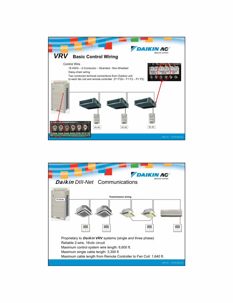
VRV Basic Control Wiring
� Control Wire � 18 AWG – 2-Conductor – Stranded - Non-Shielded
� Daisy-chain wiring
� Two conductor terminal connections from Outdoor unit to each fan coil and remote controller (F1 F2In - F1 F2 – P1 P2)
P1 P2 P1 P2P1 P2
© 2005 Daikin ACSlide 132Presentation Title : Presenter Name : Date © 2010 Daikin ACSlide 132
Daikin DIII-Net Communications
� Proprietary to Daikin VRV systems (single and three phase)� Reliable 2-wire, 16vdc circuit� Maximum control system wire length: 6,600 ft.� Maximum single cable length: 3,300 ft� Maximum cable length from Remote Controller to Fan Coil: 1,640 ft.
Transmission wiringF1 F2 In

67
© 2005 Daikin ACSlide 133Presentation Title : Presenter Name : Date © 2010 Daikin ACSlide 133
Daikin DIII-Net Basic Installation
� Robust communications with no termination resistors or signal repeaters� Avoid splices – no wire nut connections� Do not strap control wiring to conduit with ac voltage or ac wiring (24 vac)� Avoid “Star” or “Homerun” wiring� Shield not required but if used, ground one end at every component
Transmission wiringF1 F2 In
© 2005 Daikin ACSlide 134Presentation Title : Presenter Name : Date © 2010 Daikin ACSlide 134
VRV Xpress HP Wiring Report
68
© 2005 Daikin ACSlide 135Presentation Title : Presenter Name : Date © 2010 Daikin ACSlide 135
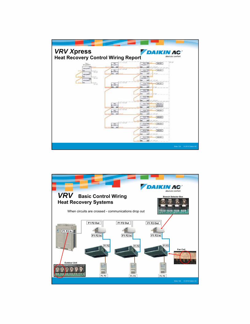
VRV XpressHeat Recovery Control Wiring Report
© 2005 Daikin ACSlide 136Presentation Title : Presenter Name : Date © 2010 Daikin ACSlide 136
VRV Basic Control WiringHeat Recovery Systems
� When circuits are crossed - communications drop out
P1 P2 P1 P2P1 P2
F1 F2 In
F1 F2 Out F1 F2 OutF1 F2 Out
F1 F2 In F1 F2 In F1 F2 In
Fan Coil
Branch Selector Box
F1 F2 F1 F2 F1 F2
Outdoor Unit

69
© 2005 Daikin ACSlide 137Presentation Title : Presenter Name : Date © 2010 Daikin ACSlide 137
VRV Basic Control WiringHeat Recovery Systems
� BS Boxes will control multiple fan coils
� Daisy chain wiring to connect all fan coils
P1 P2 P1 P2P1 P2
F1 F2 In
F1 F2 OutF1 F2 Out
F1 F2 In F1 F2 In
Branch Selector Box
F1 F2 F1 F2 F1 F2
Outdoor Unit
F1 F2
P1 P2
© 2005 Daikin ACSlide 138Presentation Title : Presenter Name : Date © 2010 Daikin ACSlide 138
VRV Basic Control WiringHeat Recovery Systems
� Single Remote Controller on multiple fan coils
� Daisy chain wiring to connect RC to all fan coils
P1 P2
F1 F2 In
F1 F2 OutF1 F2 Out
F1 F2 In F1 F2 In
Branch Selector Box
F1 F2 F1 F2 F1 F2
Outdoor Unit
F1 F2
P1 P2
P1 P2 P1 P2
70
© 2005 Daikin ACSlide 139Presentation Title : Presenter Name : Date © 2010 Daikin ACSlide 139
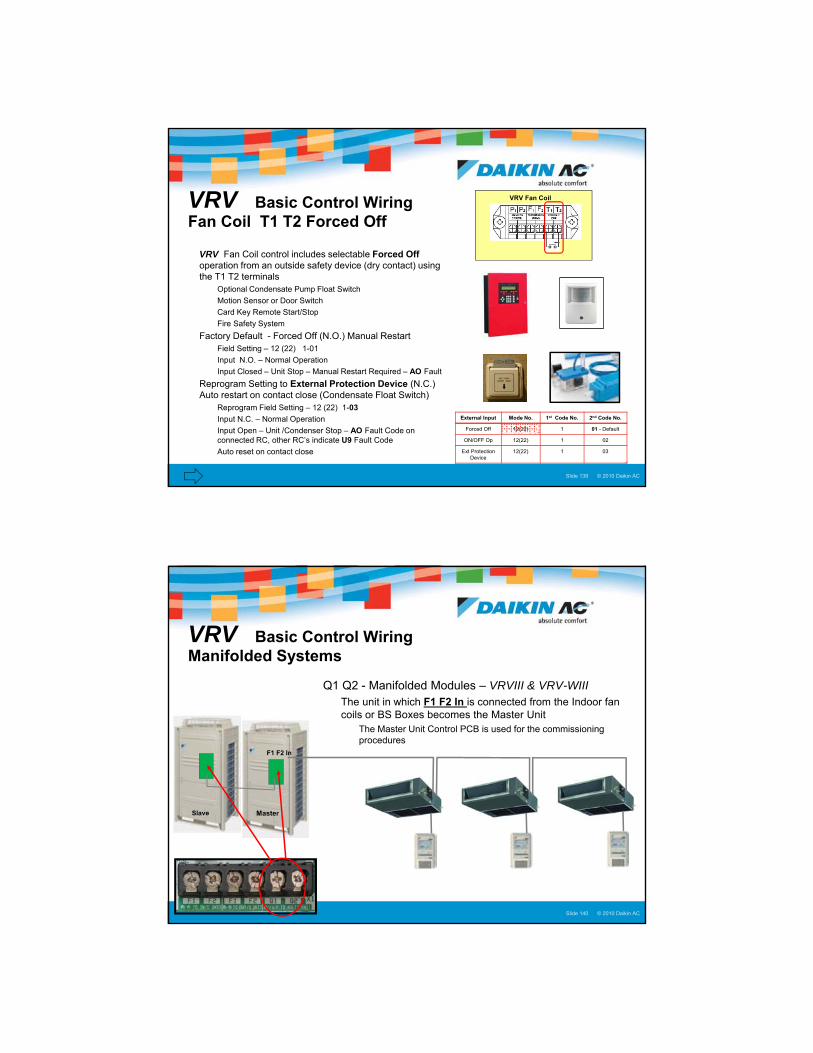
VRV Basic Control WiringFan Coil T1 T2 Forced Off
VRV Fan Coil
� VRV Fan Coil control includes selectable Forced Offoperation from an outside safety device (dry contact) using the T1 T2 terminals
� Optional Condensate Pump Float Switch
� Motion Sensor or Door Switch
� Card Key Remote Start/Stop
� Fire Safety System
� Factory Default - Forced Off (N.O.) Manual Restart � Field Setting – 12 (22) 1-01
� Input N.O. – Normal Operation
� Input Closed – Unit Stop – Manual Restart Required – AO Fault
� Reprogram Setting to External Protection Device (N.C.) Auto restart on contact close (Condensate Float Switch)
� Reprogram Field Setting – 12 (22) 1-03
� Input N.C. – Normal Operation
� Input Open – Unit /Condenser Stop – AO Fault Code on connected RC, other RC’s indicate U9 Fault Code
� Auto reset on contact close
External Input Mode No. 1st Code No. 2nd Code No.
Forced Off 12(22) 1 01 - Default
ON/OFF Op 12(22) 1 02
Ext Protection Device
12(22) 1 03
© 2005 Daikin ACSlide 140Presentation Title : Presenter Name : Date © 2010 Daikin ACSlide 140
VRV Basic Control Wiring Manifolded Systems
� Q1 Q2 - Manifolded Modules – VRVIII & VRV-WIII� The unit in which F1 F2 In is connected from the Indoor fan
coils or BS Boxes becomes the Master Unit� The Master Unit Control PCB is used for the commissioning
proceduresF1 F2 In
Slave Master
71
© 2010 Daikin AC
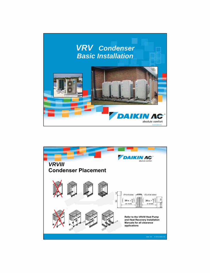
VRV Condenser Basic Installation
© 2005 Daikin ACSlide 142Presentation Title : Presenter Name : Date © 2010 Daikin ACSlide 142
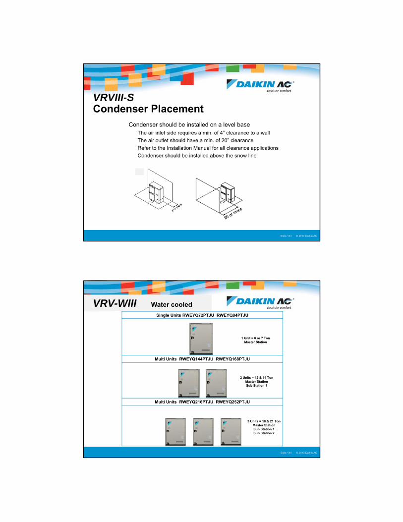
VRVIIICondenser Placement
20 in. 20 in.
Refer to the VRVIII Heat Pump and Heat Recovery Installation Manuals for all clearance applications
72
© 2005 Daikin ACSlide 143Presentation Title : Presenter Name : Date © 2010 Daikin ACSlide 143
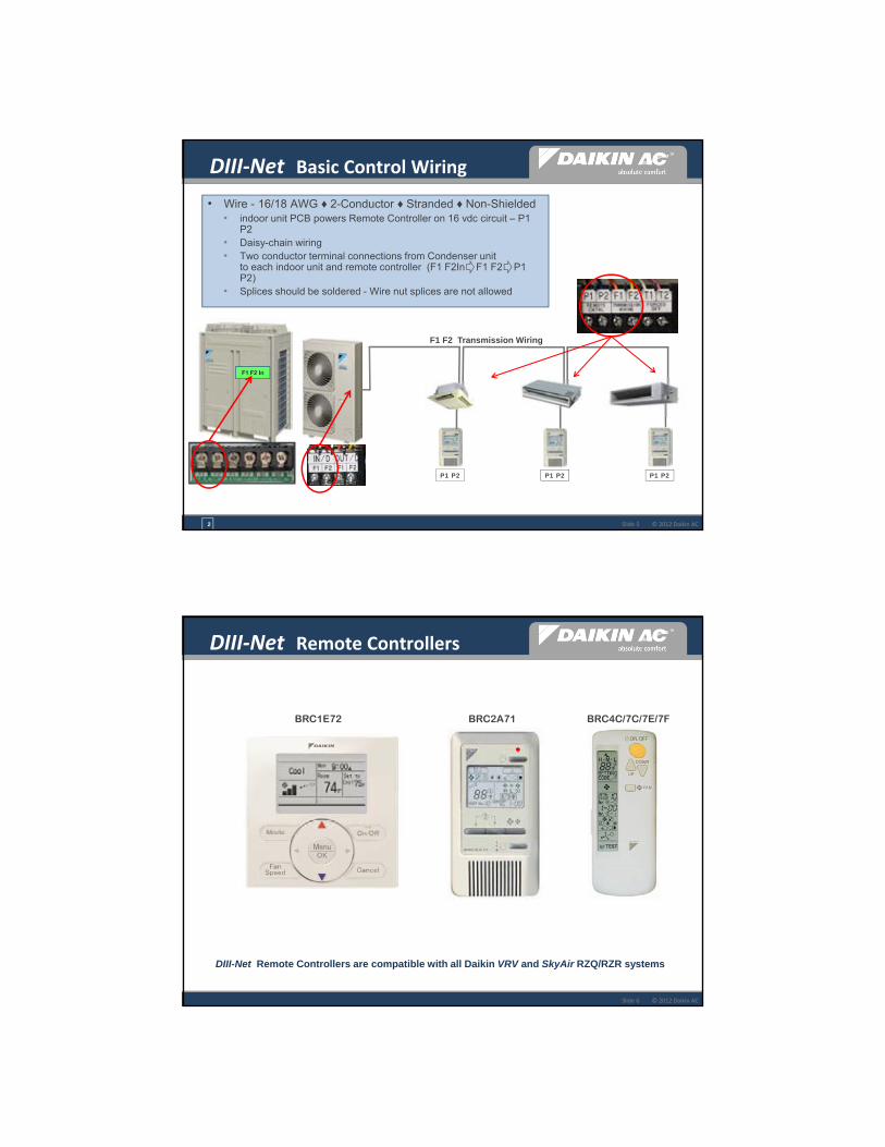
VRVIII-SCondenser Placement
� Condenser should be installed on a level base� The air inlet side requires a min. of 4” clearance to a wall
� The air outlet should have a min. of 20” clearance
� Refer to the Installation Manual for all clearance applications
� Condenser should be installed above the snow line
© 2005 Daikin ACSlide 144Presentation Title : Presenter Name : Date © 2010 Daikin ACSlide 144
Single Units RWEYQ72PTJU RWEYQ84PTJU
Multi Units RWEYQ144PTJU RWEYQ168PTJU
Multi Units RWEYQ216PTJU RWEYQ252PTJU
1 Unit = 6 or 7 Ton Master Station
2 Units = 12 & 14 Ton Master Station Sub Station 1
3 Units = 18 & 21 Ton Master Station Sub Station 1 Sub Station 2
VRV-WIII Water cooled

73
© 2005 Daikin ACSlide 145Presentation Title : Presenter Name : Date © 2010 Daikin ACSlide 145
Required Service Clearance Space
40 In
ches
(25
”)14
”
[The view from RIGHT HAND side]
Condensing Unit
Side View
12
”o
r m
ore
Space for water pipingSpace for water piping
31”
22”
3/4
CondensingUnit
Top View
Front side
Back side
�35 ½” >20”
31”
Inverter Board Heat Vent GrilleRequires min. of 12” clearance
VRV-WIII Service space
© 2005 Daikin ACSlide 146Presentation Title : Presenter Name : Date © 2010 Daikin ACSlide 146
Thank You

1
© 2012 Daikin AC
RESIDENTIAL | LIGHT COMMERCIAL | COMMERCIAL
Basic VRV Remote Controller Installation & Configuration
© 2012 Daikin ACSlide 2
• Understand the Daikin DIII‐Net control features & Installation requirements
• Identify the Daikin DIII‐Net Remote Controllers and understand the features
• Explain the installation procedures for each Remote Controller
• Explain the basic programming procedures for each Remote Controller
• Understand the Field Settings and Group Address procedures
5
Objectives

2
© 2012 Daikin ACSlide 3
Daikin DIII‐Net – The Basics
Integrated communications
architecture sharing a common protocol
Proprietary to all Daikin VRV systems
Basic 2-conductor control wire design simplifies
installation
Reliable daisy-chain communication wiring –
16vdc.
© 2012 Daikin ACSlide 4
DIII‐Net The Advantages
• The Daikin DIII-Net protocol is a system of bi-directional data packets that continuously move between the condenser and the indoor units
• Error checking insures accurate and reliable communications
• System auto-addressing as standard, simplifying commissioning
• In the startup sequence, the condenser recognizes the number and type of indoor units
• Assigns addresses for the DIII-Net communications
• No manual Rotary or DIP switches are used for system component addressing
• Control system flexibility for simple to sophisticated applications
2
3
© 2012 Daikin ACSlide 5
DIII‐Net Basic Control Wiring
P1 P2 P1 P2 P1 P2
F1 F2 In
2
F1 F2 Transmission Wiring
• Wire - 16/18 AWG ♦ 2-Conductor ♦ Stranded ♦ Non-Shielded• indoor unit PCB powers Remote Controller on 16 vdc circuit – P1
P2• Daisy-chain wiring• Two conductor terminal connections from Condenser unit
to each indoor unit and remote controller (F1 F2In F1 F2 P1 P2)
• Splices should be soldered - Wire nut splices are not allowed
© 2012 Daikin ACSlide 6
DIII‐Net Remote Controllers
BRC1E72 BRC2A71 BRC4C/7C/7E/7F
DIII-Net Remote Controllers are compatible with all Daikin VRV and SkyAir RZQ/RZR systems

4
© 2012 Daikin AC
BRC1E72
Navigation Remote Controller
© 2012 Daikin ACSlide 8
BRC1E72 Basic Features
• Large Backlit LCD Display
• Display configurable to Detailed, Standard, and Simple
• Room temperature display – Day and Time
• Selectable display languages & °F or °C Temp
• Automatic Changeover Heat Pump & Heat Recovery
• Weekly Schedule• 7-Day ♦ 5-2 ♦ 5-1-1 ♦ 1 (Everyday) schedules
• Up to 5 events per day
• Dual and Single Cool & Heat setpoints• 60 °F to 90 °F, 1 °F increments
• Configurable Setpoint Range Limitations
• Independent Setback Setpoints
• 40 °F to 95 °F, 1 °F increments
• Selectable 12/24 hour clock display
• 48 hour backup power for clock & day
• Auto-adjustable Daylight Savings Time (DST)
• Max. 16 connectable indoor units
• Optional Face Decals to hide unnecessary or locked out buttons
5
© 2012 Daikin ACSlide 9
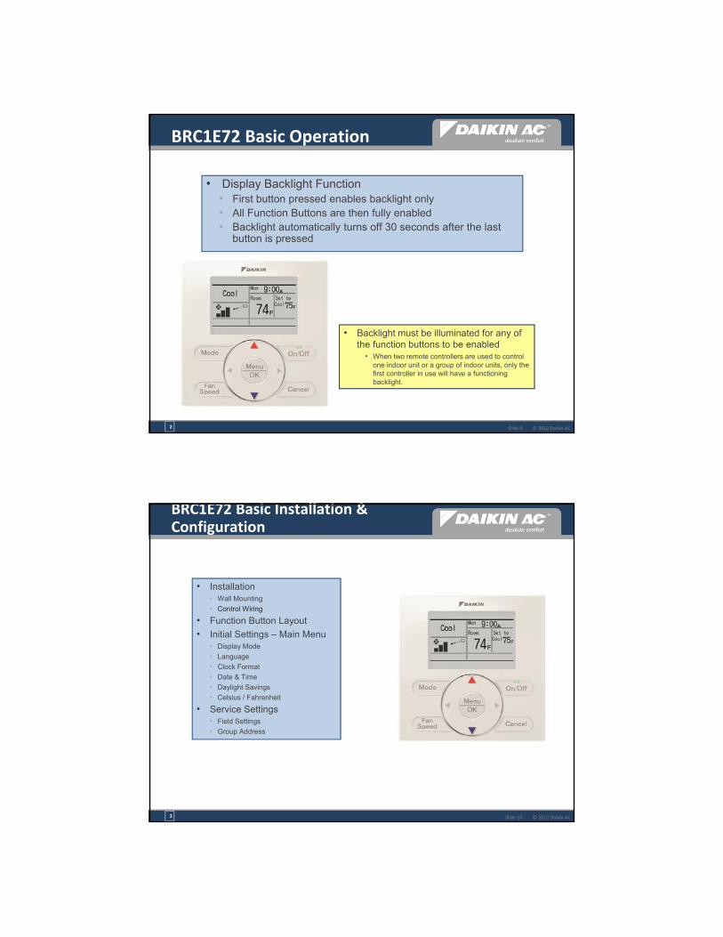
• Display Backlight Function• First button pressed enables backlight only• All Function Buttons are then fully enabled • Backlight automatically turns off 30 seconds after the last
button is pressed
• Backlight must be illuminated for any of the function buttons to be enabled
• When two remote controllers are used to control one indoor unit or a group of indoor units, only the first controller in use will have a functioning backlight.
2
BRC1E72 Basic Operation
© 2012 Daikin ACSlide 10
• Installation• Wall Mounting
• Control Wiring
• Function Button Layout
• Initial Settings – Main Menu• Display Mode
• Language
• Clock Format
• Date & Time
• Daylight Savings
• Celsius / Fahrenheit
• Service Settings• Field Settings
• Group Address
3
BRC1E72 Basic Installation & Configuration

6
© 2012 Daikin ACSlide 11
P1 P2
• Determine the proper controller location• Avoid direct sunlight
• Avoid outside walls
• Separate controller upper & lower case
• Install controller on a solid wall surface• Electrical box – 2x4 Single or 4x4 Double gang box
• Screws and drywall anchors
• Cut control wire conductor lengths with a 3/8” difference – Remove 2” of outer jacket
3
BRC1E72 Mounting & Wiring
© 2012 Daikin ACSlide 12
BRC1E72 Function Button Layout
System Mode Select Master Configuration
User Fan Speed Select
Backlit LCD Display First button pressed
System ON/OFF Op. System Status LED
Return to prev. screen Service Settings Menu Maintenance Menu
Scroll Button Up/Dn Right/Left Keys
Main Menu Select OK-Confirm Selection
7
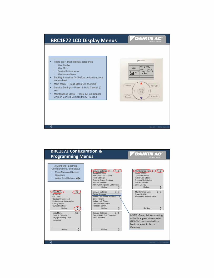
7
© 2012 Daikin ACSlide 13
BRC1E72 LCD Display Menus
4
• There are 4 main display categories• Main Display
• Main Menu
• Service Settings Menu
• Maintenance Menu
• Backlight must be ON before button functions are enabled
• Main Menu – Press Menu/OK one time
• Service Settings – Press & Hold Cancel (5 sec.)
• Maintenance Menu – Press & Hold Cancel while in Service Settings Menu (5 sec.)
© 2012 Daikin ACSlide 14
BRC1E72 Configuration & Programming Menus
3 Menus for Settings, Configurations, and Status• Menu Name and Number
• Selections
• Active Scroll Buttons
Main Menu 1 / 2Schedule Off Timer Celsius / Fahrenheit Maintenance Information Configuration Current Settings
Setting
Main Menu 2 / 2Clock & Calendar Daylight Saving Time Language
Setting
Service Settings 1 / 3Test Operation Maintenance Contract Field Settings Energy Saving Options Prohibit Buttons Minimum Setpoints Differential
Setting
Maintenance Menu 1 / 2Model Name Operation Hours Indoor Unit Status Outdoor Unit Status Forced Defrost Error Display
Setting
Maintenance Menu 2 / 2Swap Unit No. Addressed Sensor Value
Setting
Service Settings 2 / 3Group Address Indoor Unit AirNet Address Error History Indoor Unit Status Outdoor Unit Status Forced Fan On
Setting
Service Settings 3 / 3Switch Main Sub Controller Filter Indicator
Setting
NOTE: Group Address setting will only appear when system (DIII-Net) is connected to a Multi-zone controller or Gateway
4

8
© 2012 Daikin ACSlide 15
BRC1E72 Power up – Initial Settings
• Power is provided to the remote controller from the indoor unit PCB (16vdc – P1 P2)
• Upon Power Up of the indoor unit, the display on the Remote Controller will verify communications, and within 15 seconds the display will go into the “Standard” display mode.
• This Standard Display is very basic, and does not show the day of the week, current time, or space (room) ambient temperature.
• “Initial Settings” are required to configure a new BRC1E72 Remote Controller. • The “Initial Settings” are performed from the Main
Menu
2
Standard Display - Factory Default
© 2012 Daikin AC
BRC1E72
Main Menu

9
© 2012 Daikin ACSlide 17
• English (Default) - French / Spanish selectable
• Language: Main Menu Language
MENU OK
PRESS
BRC1E72 Initial Setting –Language
© 2012 Daikin ACSlide 18
• Fahrenheit (default) – Celsius selectable
• Main Menu Fahrenheit to Celsius
MENU OK
PRESS
BRC1E72 Initial Setting –Fahrenheit to Celsius
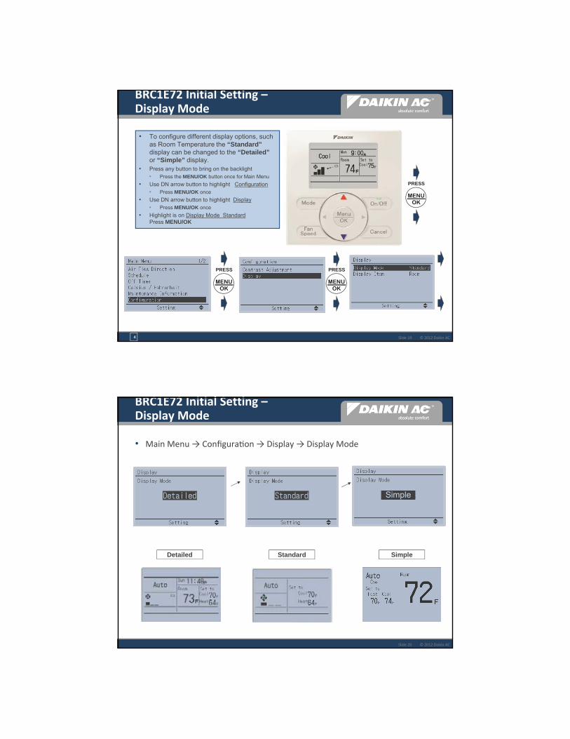
10
© 2012 Daikin ACSlide 19
BRC1E72 Initial Setting –Display Mode
• To configure different display options, such as Room Temperature the “Standard” display can be changed to the “Detailed”or “Simple” display.
• Press any button to bring on the backlight• Press the MENU/OK button once for Main Menu
• Use DN arrow button to highlight Configuration• Press MENU/OK once
• Use DN arrow button to highlight Display• Press MENU/OK once
• Highlight is on Display Mode Standard Press MENU/OK
MENU OK
PRESS
MENU OK
PRESS
4
MENU OK
PRESS
© 2012 Daikin ACSlide 20
• Main Menu → Configura on → Display → Display Mode
StandardDetailed Simple
Simple
BRC1E72 Initial Setting –Display Mode

11
© 2012 Daikin ACSlide 21
BRC1E72 Initial Setting –Display Item
• The Room Temperature display is the default setting
• Backlight must be ON
• Press the MENU/OK button once
• Use DN arrow button to highlight Configuration• Press MENU/OK once
• Use arrow button to highlight Display• Press MENU/OK once
• Highlight is on Display Mode
• Use DN arrow key to select Display Item Room• Press MENU/OK once
• Pressing the displays the following:
Room Temperature
MENU OK
PRESS
MENU OK
PRESS
MENU OK
PRESS
4
MENU OK
PRESS
© 2012 Daikin ACSlide 22
Configurable display mode – Detailed, Standard, and Simple New
BRC1E72 Display Overview

12
© 2012 Daikin ACSlide 23
• Following display configurations are available through field settings
• Applicable to all three display mode
• Display OFF instead of Mode while the unit is off
(1b‐13‐02)
• No setpoint display while the unit is off
(1b‐12‐02)
• No Fan Speed display
(1b‐15‐02)
BRC1E72 Initial Setting –Display Configurations
ON
OFF
© 2012 Daikin ACSlide 24
• Status icon and other information on the display can be eliminated through Field Setting
• e.g. “Central Control” icon is not necessary in hotel room
Item Available Display mode Field SettingDetailed Standard Simple Code Choice
STSANDBY icon
X X X 1b-7 01: display in Defrost or Hot Start02: Not display
Day/Clock X 1b-11 01: display02: Not display
CENTRAL CONTROLicons
X X 1e-9 (MASTER CONTROL icon too)01: display02: Not display
Prohibit button message
X X X 1e-10 01: Key lock icon blinks for 5 sec(Key lock icon is not displayed in Simple display mode)
02: Message
BRC1E72 Status Icon Elimination
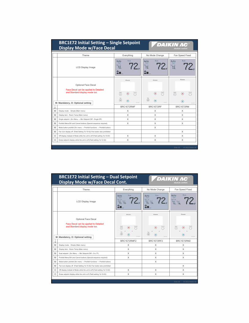
13
© 2012 Daikin ACSlide 25
BRC1E72 Initial Setting – Single Setpoint Display Mode w/Face Decal
Theme Everything No Mode Change Fan Speed Fixed
LCD Display Image
Optional Face Decal
BRC1E72RMF BRC1E72RF BRC1E72RM
M Display mode - Simple (Main menu) X X X
M Display item - Room Temp (Main menu) X X X
M Single setpoint (Srv Menu → Min Setpoint Diff - Single SP) X X X
M Prohibit Menu/OK and Cancel buttons (Special sequence required) X X X
M Mode button prohibit (Srv menu → Prohibit functions → Prohibit button) X
M Fan icon display off (Field Setting 1b-15-02) Fan button also prohibited X
O Off display instead of Mode while the unit is off (Field setting 1b-13-02) X X X
O Erase setpoint display while the unit is off (Field setting 1b-12-02) X X X
M: Mandatory, O: Optional setting
Face Decal can be applied to Detailed and Standard display mode too.
© 2012 Daikin ACSlide 26
BRC1E72 Initial Setting – Dual SetpointDisplay Mode w/Face Decal Cont.
Theme Everything No Mode Change Fan Speed Fixed
LCD Display Image
Optional Face Decal
BRC1E72RMF2 BRC1E72RF2 BRC1E72RM2
M Display mode - Simple (Main menu) X X X
M Display item - Room Temp (Main menu) X X X
M Dual setpoint (Srv Menu → Min Setpoint Diff - 0 to 7F) X X X
M Prohibit Menu/OK and Cancel buttons (Special sequence required) X X X
M Mode button prohibit (Srv menu → Prohibit functions → Prohibit button) X
M Fan icon display off (Field Setting 1b-15-02) Fan button also prohibited X
O Off display instead of Mode while the unit is off (Field setting 1b-13-02) X X X
O Erase setpoint display while the unit is off (Field setting 1b-12-02) X X X
M: Mandatory, O: Optional setting
Face Decal can be applied to Detailed and Standard display mode too.

14
© 2012 Daikin ACSlide 27
Single Setpoint Face Decals
Dual Setpoint Face Decals
BRC1E72 Optional Face Decals
© 2012 Daikin ACSlide 28
• To display Day of the Week and Time• Backlight must be ON
• Press the MENU/OK button once
• Use DN arrow button to highlight Clock & Calendar • Press MENU/OK once
• Use arrow button to highlight Date & Time• Press MENU/OK once
• Using the scroll arrows – set the Year, Month, Day, and current Time AM/PM
MENU OK
PRESS
MENU OK
PRESS
3
MENU OK
PRESS
BRC1E72 Initial Setting –Date & Time

15
© 2012 Daikin ACSlide 29
• Save the Date & Time settings: “Yes”• Press MENU/OK once
• Save the settings - Highlight Yes• Press MENU/OK
• Main Display should now be complete
MENU OK
PRESS
MENU OK
PRESS
2
BRC1E72 Initial Setting –Date & Time Cont.
© 2012 Daikin ACSlide 30
• 12/24 Hour Clock Format Change• 12 hr. clock format is the default
• 12 hr. is changed to 24 hr. through Clock & Calendar menu
• Press the Menu/OK button after each screen selection
1
BRC1E72 Initial Setting –Clock Format
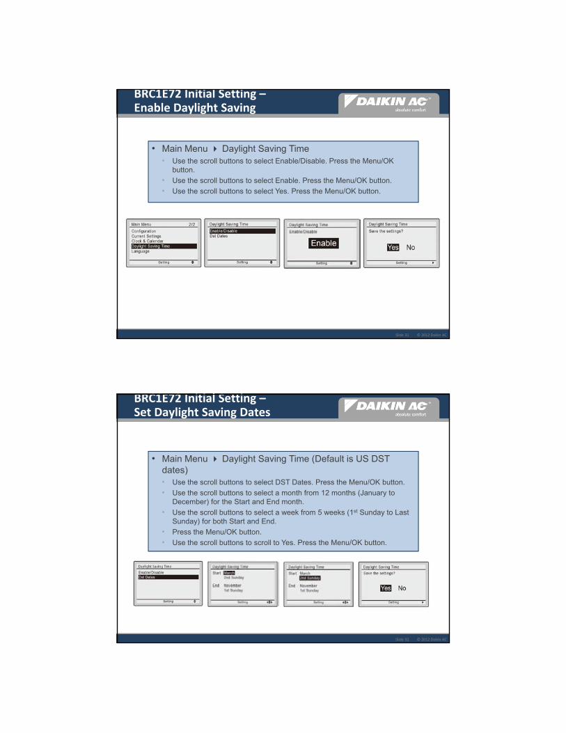
16
© 2012 Daikin ACSlide 31
• Main Menu Daylight Saving Time• Use the scroll buttons to select Enable/Disable. Press the Menu/OK
button.
• Use the scroll buttons to select Enable. Press the Menu/OK button.
• Use the scroll buttons to select Yes. Press the Menu/OK button.
BRC1E72 Initial Setting –Enable Daylight Saving
© 2012 Daikin ACSlide 32
BRC1E72 Initial Setting –Set Daylight Saving Dates
• Main Menu Daylight Saving Time (Default is US DST dates)• Use the scroll buttons to select DST Dates. Press the Menu/OK button.
• Use the scroll buttons to select a month from 12 months (January to December) for the Start and End month.
• Use the scroll buttons to select a week from 5 weeks (1st Sunday to Last Sunday) for both Start and End.
• Press the Menu/OK button.
• Use the scroll buttons to scroll to Yes. Press the Menu/OK button.
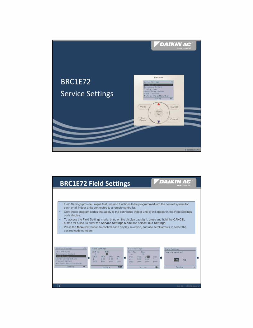
17
© 2012 Daikin AC
BRC1E72
Service Settings
© 2012 Daikin ACSlide 34
BRC1E72 Field Settings
• Field Settings provide unique features and functions to be programmed into the control system for each or all indoor units connected to a remote controller.
• Only those program codes that apply to the connected indoor unit(s) will appear in the Field Settings code display.
• To access the Field Settings mode, bring on the display backlight: press and hold the CANCELbutton for 5 sec. to enter the Service Settings Mode and select Field Settings
• Press the Menu/OK button to confirm each display selection, and use scroll arrows to select the desired code numbers
2

18
© 2012 Daikin ACSlide 353
BRC1E72 Indoor Unit Field Settings
• There are two Modes for each setting; “Group” & “Individual”
• The first set of 2-digit numbers refers to Group and Individual, Group is the first number & Individual is in the parenthesis
• “Group ##” is used if there is only one indoor unit per Remote Controller or the setting you chose is intended for all indoor units being controlled by the same Remote Controller
• “Individual (##)” is used when there is more than one indoor unit being controlled by one Remote Controller and the settings being programmed are intended for one of the indoor units in the group
© 2012 Daikin ACSlide 36
EXAMPLE: Field Setting for assigning the room temperature sensor
5
BRC1E72 Indoor Unit Field Settings
• Field Setting codes are comprised of 3 segments: [Example: 10 – 2 - 03]• Mode No. – Program Setting for 1 indoor unit or Group
• First Code No. - Setting Contents
• Second Code No. - Specific Operation or Setting
• Specific Field Setting codes for a particular indoor unit can be found in the Indoor Unit Installation Manual or Engineering Manual• Any Field Setting codes that do not apply to the particular indoor unit will not be configurable
• Field Settings are stored in the non-volatile memory in the Control PCB of the Indoor Unit or Remote Controller

19
© 2012 Daikin ACSlide 37
Field Setting Availability by Indoor Unit Type
Mode No. 10 12First Code No. 2 5 6 0 1 2 (***) 3 6 8
Second Code No. 01/02 03 01/02 01/02 01/03/04 01/02/03 01/02 01/02 03 01/02/03 01/02
FXSQ_MVJU X X** X** X X X X (02) X X** X* n/aFXMQ_MVJU X X* X* X X X X (02) X X* X* n/aFXMQ72/96MVJU X X X X X X X (02) X X X n/a
FXMQ_PVJUFBQ_PVJU
X X X X X X X (02) X X X n/a
FXDQ_MVJU X X X X X X X (02) X X n/a n/a
FXTQ_PVJUFTQ_PAVJUFTQ_PBVJU
X X X X X X X (02) X X X n/a
BEQ_MVJLR1 (FXOQ)
X X X X X X X (02) X X X* n/a
FXLQ_MVJU X X* X* X X X X (02) X X* X* n/aFXNQ_MVJU X X* X* X X X X (02) X X* X* n/a
FXAQ_MVJUFAQ_MVJUFAQ_PVJU
X X* X* X n/a X X (01) X X* n/a n/a
FXAQ_PVJU X X X X n/a X X (01) X X n/a n/aFXZQ_M7VJU X X* X* X X X X (01) X X* X* n/a
FXFQ_MVJUFCQ_MVJUFCQ_PVJU
X n/a n/a n/a X X X (01) X n/a n/a n/a
FXFQ_PVJUFCQ_PAVJU
X X X X X X X (01) X X X X
FXHQ_MVJUFHQ_MVJUFHQ_PVJU
X n/a n/a n/a X X X (01) X n/a n/a n/a
Availability of Indoor Unit Field Settings (Control Related) As of 12/01/2012
* Field settings highlighted in orange may not be available in units manufactured before 9/1/2009. ** Field settings highlighted in blue may not be available in units manufactured before 1/1/2007.*** Factory default value is indicated in parenthesis.
© 2012 Daikin ACSlide 38
Field Settings – Indoor unitField Settings – Indoor Units (Control Related)
1. Field settings are normally applied to the entire remote control group, however if individual indoor units in the remote control group require specific settings or for confirmation that settings have been established, utilize the mode number in parenthesis.
2. Any features not supported by the installed indoor unit will not be displayed.3. When mode 10-2-01 is selected, only the return air temperature value is reported to the multi-zone controller.4. The actual default deadband value will depend upon the indoor unit model.
Mode No.(Note 1)
First Code No. Description Second Code No. (Note 2)(Cells in bold are factory default settings)01 02 03 04
10(20) 2 Priority of thermistor sensors for space temperature control
The return air thermistor is primary and the remote controller thermistorIs secondary.
Only the return air thermistor will be utilized.
Only the remote controller thermistor will be utilized.
--
5 Room temperature value reported to multi-zone controllers
Return air thermistor Thermistor designated by 10-2 above (Note 3)
-- --
6 The remote controller thermistor is used in Remote Controller Group
No Yes -- --
12(22) 0 KRP1B71 X1-X2 status output Indoor unit Thermo-On/Off status
-- Indoor unit Operation On/Off status
Indoor unit Alarm status
1 Indoor unit T1-T2 input Forced Off
Closed Contact-Indoor unit is forced off and Central Control icon is displayed. Unit cannot be turned on manually. Operation can be overridden by central control.
Open Contact-Indoor unit can resume normal operation. Unit must be turned on manually or by central control.
On/Off
Closed Contact-Indoor unit is turned on.
Open Contact-Indoor unit is turned off.
Unit responds to last command, i.e., unit can be turned on manually or by central control after circuit has opened. Operation is prohibited when remote controller On/Off control is restricted by a multi-zone controller.
External Protection Device
Closed contact-Unit shall resume normal operation.
Open contact-Unit shall shut down and generate an A0 error.
2 Thermo-On/Off deadband (Note 4) 2F (1C) 1F (0.5C) -- --
3 Fan Speed in Heating Thermo-Off LL User set Off --
6 Fan Speed in Cooling Thermo-Off LL User set Off --
8 Return air sensor offset 2C None(for remote sensor)
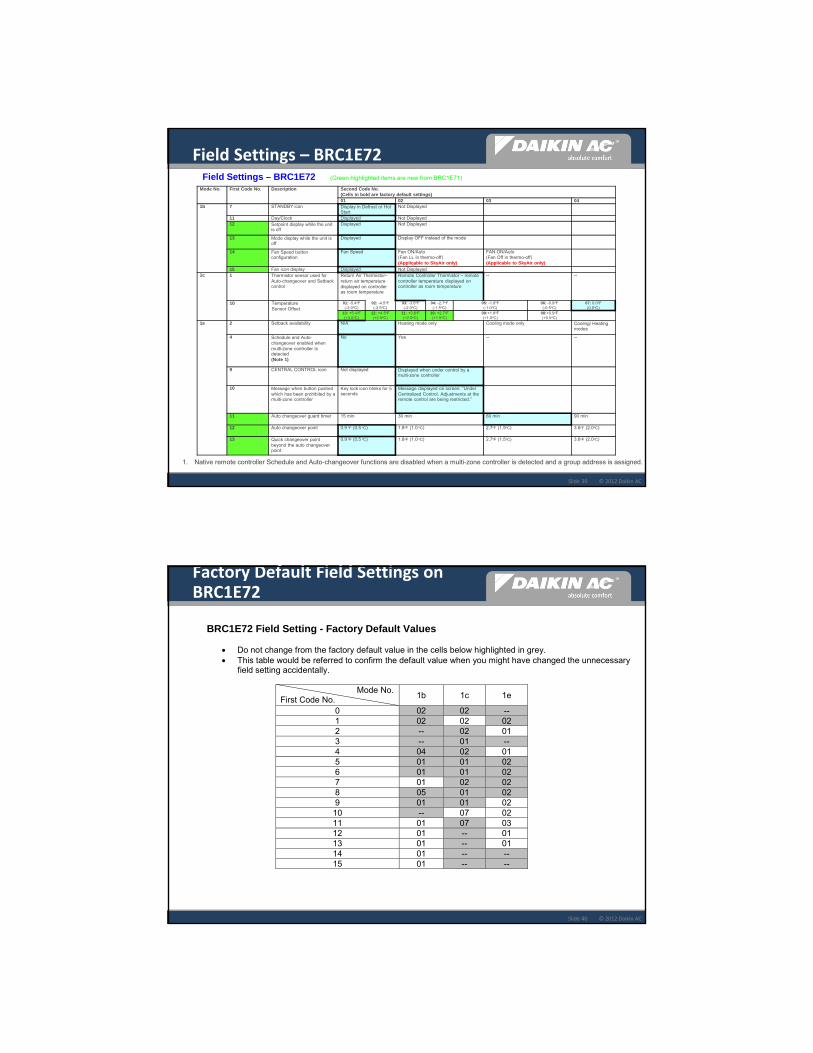
20
© 2012 Daikin ACSlide 39
Field Settings – BRC1E72
Mode No. First Code No. Description Second Code No.(Cells in bold are factory default settings)01 02 03 04
1b 7 STANDBY icon Display in Defrost or Hot Start
Not Displayed
11 Day/Clock Displayed Not Displayed12 Setpoint display while the unit
is offDisplayed Not Displayed
13 Mode display while the unit is off
Displayed Display OFF instead of the mode
14 Fan Speed button configuration
Fan Speed Fan ON/Auto(Fan LL in thermo-off)(Applicable to SkyAir only)
FAN ON/Auto(Fan Off in thermo-off)(Applicable to SkyAir only)
15 Fan icon display Displayed Not Displayed1c 1 Thermistor sensor used for
Auto-changeover and Setback control
Return Air Thermistor–return air temperature displayed on controller as room temperature
Remote Controller Thermistor – remote controller temperature displayed on controller as room temperature
-- --
10 Temperature Sensor Offset
01: -5.4oF(-3.0oC)
02: -4.5oF(-2.5oC)
03: -3.6oF(-2.0oC)
04: -2.7oF(-1.5oC)
05: -1.8oF(-1.0oC)
06: -0.9oF(-0.5oC)
07: 0.0oF(0.0oC)
13: +5.4oF(+3.0oC)
12: +4.5oF(+2.5oC)
11: +3.6oF(+2.0oC)
10: +2.7oF(+1.5oC)
09:+1.8oF(+1.0oC)
08:+0.9oF(+0.5oC)
1e 2 Setback availability N/A Heating mode only Cooling mode only Cooling/ Heating modes
4 Schedule and Auto-changeover enabled when multi-zone controller is detected(Note 1)
No Yes -- --
9 CENTRAL CONTROL icon Not displayed Displayed when under control by a multi-zone controller
10 Message when button pushed which has been prohibited by a multi-zone controller
Key lock icon blinks for 5 seconds
Message displayed on screen: “Under Centralized Control. Adjustments at the remote control are being restricted.”
11 Auto changeover guard timer 15 min 30 min 60 min 90 min
12 Auto changeover point 0.9 oF (0.5 oC) 1.8oF (1.0 oC) 2.7oF (1.5oC) 3.6oF (2.0oC)
13 Quick changeover point beyond the auto changeover point
0.9 oF (0.5 oC) 1.8oF (1.0 oC) 2.7oF (1.5oC) 3.6oF (2.0oC)
Field Settings – BRC1E72 (Green highlighted items are new from BRC1E71)
1. Native remote controller Schedule and Auto-changeover functions are disabled when a multi-zone controller is detected and a group address is assigned.
© 2012 Daikin ACSlide 40
Factory Default Field Settings on BRC1E72
BRC1E72 Field Setting - Factory Default Values
Do not change from the factory default value in the cells below highlighted in grey. This table would be referred to confirm the default value when you might have changed the unnecessary
field setting accidentally.
Mode No. First Code No. 1b 1c 1e
0 02 02 -- 1 02 02 02 2 -- 02 01 3 -- 01 -- 4 04 02 01 5 01 01 02 6 01 01 02 7 01 02 02 8 05 01 02 9 01 01 02 10 -- 07 02 11 01 07 03 12 01 -- 01 13 01 -- 01 14 01 -- -- 15 01 -- --

21
© 2012 Daikin ACSlide 41
BRC1E72 Sensor ‐ Field Settings
• To use only BRC1E72 sensor, set field settings as 10‐2‐03, 10‐5‐02, & 1C‐1‐02
• 10‐2‐03, 10‐5‐02 availability
• always available: FXMQ_P, FXTQ_P, FXAQ_P, FXFQ_P, FBQ_P, FTQ_P, FCQ_PA
• All _M series (except FXFQ, FXHQ, FCQ, FHQ)
• Manufactured after 9/1/2009: always available
• Manufactured before 9/1/2009: confirm if 10‐2‐03, 10‐5‐02 are available.
• never available: FXFQ_MVJU, FXHQ_MVJU, FCQ_MVJU, FCQ_PVJU, FHQ_MVJU, FHQ_PVJU
• Set 10‐2‐02 and use Remote sensor (or Return air sensor) only
• Field setting – 10‐2, 10‐5 and 1C‐1 settings are necessary
Which single sensor is used?
For indoor unit control
(Cool/Dry/Heat VRV and thermo-on/off
control)
For BRC1E72 control
(Auto changeover and setback control)
For Multi-zone Control
BRC1E72 10-2-03 1C-1-02 (default) 10-5-02
Remote sensor
(or Return air sensor)
10-2-02
(it is always available)
1C-1-01 10-5-01 (default)
Recommended
© 2012 Daikin ACSlide 42
Initial Setting – Setpoint Range
• Service Settings → Energy Saving Op ons → Setpoint Range Limitation
• User can change the setpoint within the range
• Setup setpoint is configurable between
“Cool setpoint max + 2oF (1oC)” and “95oF”
• Setback setpoint is configurable between
“Heat setpoint min – 2oF (1oC)” and “40oF”
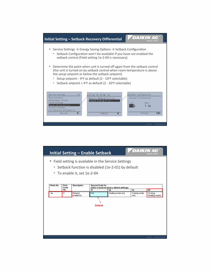
22
© 2012 Daikin ACSlide 43
Initial Setting – Setback Recovery Differential
• Service Settings → Energy Saving Op ons → Setback Configura on
• Setback Configuration won’t be available if you have not enabled the setback control (Field setting 1e‐2‐04 is necessary).
• Determine the point when unit is turned off again from the setback control (the unit is turned on by setback control when room temperature is above the setup setpoint or below the setback setpoint)
• Setup setpoint ‐ 4oF as default (2 ‐ 10oF selectable)
• Setback setpoint + 4oF as default (2 ‐ 10oF selectable)
© 2012 Daikin ACSlide 44
Initial Setting – Enable Setback
• Field setting is available in the Service Settings
• Setback function is disabled (1e‐2‐01) by default
• To enable it, set 1e‐2‐04
Default

23
© 2012 Daikin ACSlide 45
Initial Setting – Prohibit R/C buttons
• To configure which buttons to prohibit
• Service Setting → Prohibit Func ons → Prohibit Bu ons
• Enable = permit
• Disable = prohibit
• Disable in Off = prohibit only while the unit is off
• To enable Prohibit Buttons – see next slide
Operable buttons
Menu/OK and Cancel button will be prohibited when any of the buttons are prohibited.
© 2012 Daikin ACSlide 46
Enable/Disable Prohibit Buttons
• To enable Prohibit Buttons, holding Right arrow button, push Mode, Fan Speed and Cancel at the same time while the main screen is displayed
• To release it, same as above
• Then if you push prohibited button, you will see a key icon blinking three times
• Key icon is available in Detailed and Standard display mode only (In simple display mode Key icon is not displayed)
These buttons can be pressed from above the optional Face Decals to enable/disable prohibit buttons

24
© 2012 Daikin ACSlide 47
Initial Setting – Prohibit Mode
• To configure modes which cannot be selected by a user
• Service Setting → Prohibit Func ons → Prohibit Mode
• Enable = selectable, Disable = not selectable
© 2012 Daikin ACSlide 48
Initial Setting – Min. Setpoint Differential
• Service Settings → Min Setpoint Differen al
• Configurable to 0 – 8oF (0 – 4oC), default is 2oF (1oC) for Dual SP or Single SP
• When the differential is set to 0 – 8F, Cool and Heat setpoints are maintained as
• Cool setpoint ≥ Heat setpoint + Differential
• When Single SP is set, there is one setpoint for Cool and Heat
• When a multi‐zone controller is connected, the differential is set to Single SP automatically.

25
© 2012 Daikin ACSlide 49
Schedule, Auto changeover disabled
• When a group address is assigned and a multi‐zone controller is connected, Schedule and Auto changeover on BRC1E72 are disabled.
• To prevent conflict between BRC1E72 and I‐TC or BMS control
• Min. setpoint differential would be set at Single SP• When setpoint is changed from a multi‐zone controller, the both
cooling and heating setpoints are overridden with the same value.
• Field setting 1e‐4‐02 re‐enables BRC1E72 Schedule and Auto changeover. Make sure Schedule/Auto changeover is disabled in the I‐TC/BMS to prevent conflict.
Default
© 2012 Daikin ACSlide 50
Automatic changeover in Heat Pump and Heat Recovery Systems
• At 1oF above cooling or 1oF below heating setpoint (default)
• Configurable between 1oF – 4oF (improved)
• Another 1oF above cooling or 1oF below heating changeover points immediate changeover ignoring guard timer (new)
• Configurable between 1oF – 4oF (new)
• Guard timer to prevent frequent mode change (improved)
• 15, 30, 60 (default), or 90 minute guard timer settable
BRC1E72 ‐ Auto-changeover
Cooling SP
Heating SP
Min Differential (0 to 7F)
Change to Cooling (with Guard Timer)
Surely Change to Cooling
(1 to 4F)
(1 to 4F)
(1 to 4F)
(1 to 4F)
Surely Change to Heating
Change to Heating (with Guard Timer)
Field Setting 1e-12
Field Setting 1e-13
Field Setting 1e-11
Field Setting 1e-12
Field Setting 1e-12
Field Setting 1e-13
Field Setting 1e-13

26
© 2012 Daikin ACSlide 51
BRC1E72 ‐ Auto‐changeoverExample #1 = Dual Setpoints
1oF
C/H Differential = 2oF (Configurable to 0‐7F)
Cooling Setpoint = 72oF
Heating Setpoint = 70oF
1oF
1oF
1oF
68oF Surely Change to Heating
74oF Surely Change to Cooling
73oF Change to Cooling(with Guard Timer)
69oF Change to Heating(with Guard Timer)
(Configurable to 1‐4F)
(Configurable to 1‐4F)
(Configurable to 1‐4F)
(Configurable to 1‐4F)
Example #2 = Single Setpoint
2oFSingleSetpoint = 71oF
2oF
1oF
1oF
68oF Surely Change to Heating
74oF Surely Change to Cooling
73oF Change to Cooling (with Guard Timer)
69oF Change to Heating (with Guard Timer)
(Configurable to 1‐4F)
(Configurable to 1‐4F)
(Configurable to 1‐4F)
(Configurable to 1‐4F)
© 2012 Daikin ACSlide 52
• When a multi-zone controller such as the iTouch Controller, iTouch Manager, or BMS Gateways are connected, Group Address settings must be configured through the Service Settings mode.
• A Group consists of 1 to 16 indoor units connected to the same Remote Controller.
• There are 64 Group Addresses available
• 1-00 to 1-15
• 2-00 to 2-15
• 3-00 to 3-15
• 4-00 to 4-15
BRC1E72 Settings Group Address
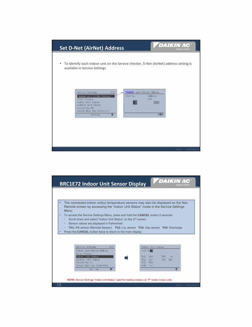
27
© 2012 Daikin ACSlide 53
Set D‐Net (AirNet) Address
• To Identify each indoor unit on the Service checker, D‐Net (AirNet) address setting is available in Service Settings
Indoor
Indoor
© 2012 Daikin ACSlide 54
BRC1E72 Indoor Unit Sensor Display
• The connected indoor unit(s) temperature sensors may also be displayed on the Nav. Remote screen by accessing the “Indoor Unit Status” mode in the Service Settings Menu
• To access the Service Settings Menu, press and hold the CANCEL button 5 seconds
• Scroll down and select “Indoor Unit Status” on the 2nd screen
• Sensor values are displayed in Fahrenheit
• Th1: RA sensor (Remote Sensor) Th2: Liq. sensor Th3: Gas sensor Th4: Discharge
• Press the CANCEL button twice to return to the main display
NOTE: Service Settings “Indoor Unit Status” used for reading sensors on “P” series indoor units
2

28
© 2012 Daikin ACSlide 55
Indoor Unit Temperatures
• Service Settings → Indoor Unit Status
• Applicable for P‐series indoor units (FXMQ_P, FXTQ_P)
Th # Description
Th1 Return air sensor (Remote sensor) temperature
Th2 Liquid line temperature
Th3 Gas line temperature
Th4 Discharge air temperature (FXMQ_P only)
Th5 Remote controller sensor temperature
Th6 Temperature to be used for indoor unit control(See field setting 10(20) - 2)
© 2012 Daikin ACSlide 56
BRC1E72 Indoor Unit Address ID
4
• To determine the group address and the unit number assigned to an indoor unit in a group, use the “Forced Fan ON” mode (indoor units must be turned OFF) • Press and hold the CANCEL button for 5 sec. - Service Settings
• Scroll down to the second “Service Settings” screen and select Forced Fan On
• The “Forced Fan ON” screen appears with system address (Unit No.) “0” • Within several seconds the indoor unit assigned unit “0” will turn on
• Use the scroll arrow to change the Unit No. from “0” to 1, 2, 3 etc. and the fans in those indoor units will energize in HH accordingly
• Press CANCEL button twice to de-energize the fan and return to Main Display
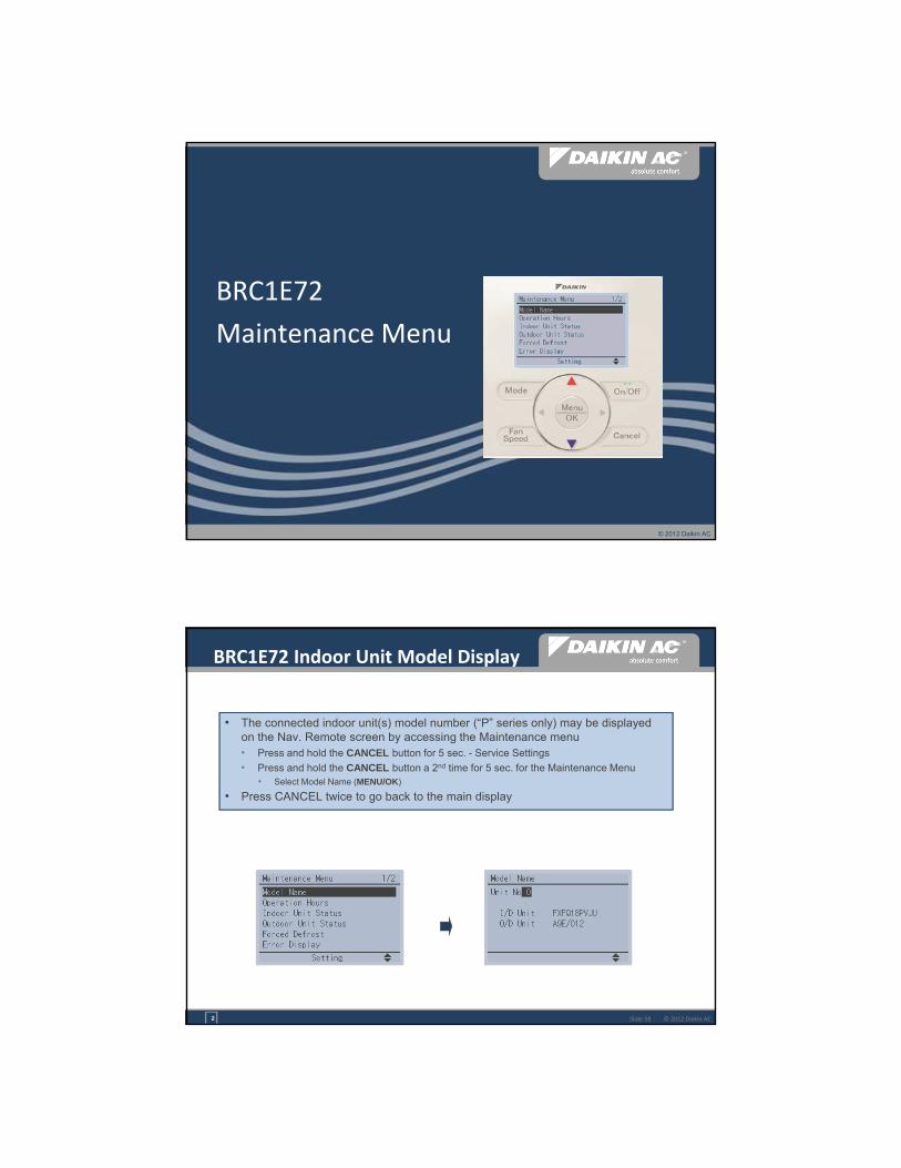
29
© 2012 Daikin AC
BRC1E72
Maintenance Menu
© 2012 Daikin ACSlide 58
BRC1E72 Indoor Unit Model Display
• The connected indoor unit(s) model number (“P” series only) may be displayed on the Nav. Remote screen by accessing the Maintenance menu• Press and hold the CANCEL button for 5 sec. - Service Settings
• Press and hold the CANCEL button a 2nd time for 5 sec. for the Maintenance Menu • Select Model Name (MENU/OK)
• Press CANCEL twice to go back to the main display
2
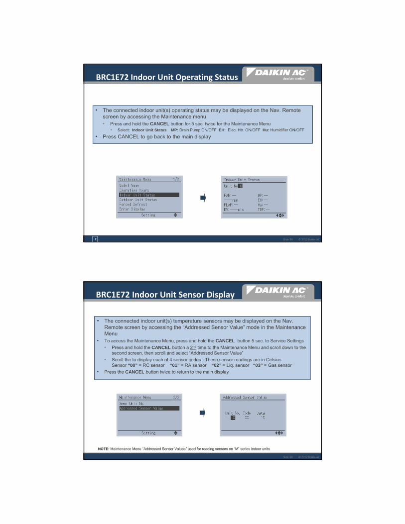
30
© 2012 Daikin ACSlide 59
BRC1E72 Indoor Unit Operating Status
• The connected indoor unit(s) operating status may be displayed on the Nav. Remote screen by accessing the Maintenance menu• Press and hold the CANCEL button for 5 sec. twice for the Maintenance Menu
• Select: Indoor Unit Status MP: Drain Pump ON/OFF EH: Elec. Htr. ON/OFF Hu: Humidifier ON/OFF
• Press CANCEL to go back to the main display
2
© 2012 Daikin ACSlide 60
• The connected indoor unit(s) temperature sensors may be displayed on the Nav. Remote screen by accessing the “Addressed Sensor Value” mode in the Maintenance Menu
• To access the Maintenance Menu, press and hold the CANCEL button 5 sec. to Service Settings
• Press and hold the CANCEL button a 2nd time to the Maintenance Menu and scroll down to the second screen, then scroll and select “Addressed Sensor Value”
• Scroll the to display each of 4 sensor codes - These sensor readings are in CelsiusSensor “00” = RC sensor “01” = RA sensor “02” = Liq. sensor “03” = Gas sensor
• Press the CANCEL button twice to return to the main display
NOTE: Maintenance Menu “Addressed Sensor Values” used for reading sensors on “M” series indoor units
BRC1E72 Indoor Unit Sensor Display
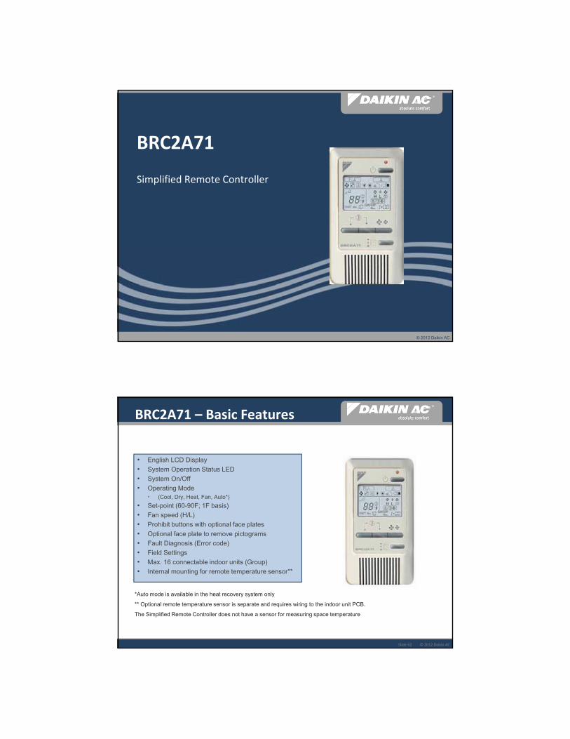
31
© 2012 Daikin AC
BRC2A71
Simplified Remote Controller
© 2012 Daikin ACSlide 62
BRC2A71 – Basic Features
• English LCD Display
• System Operation Status LED
• System On/Off
• Operating Mode • (Cool, Dry, Heat, Fan, Auto*)
• Set-point (60-90F; 1F basis)
• Fan speed (H/L)
• Prohibit buttons with optional face plates
• Optional face plate to remove pictograms
• Fault Diagnosis (Error code)
• Field Settings
• Max. 16 connectable indoor units (Group)
• Internal mounting for remote temperature sensor**
*Auto mode is available in the heat recovery system only
** Optional remote temperature sensor is separate and requires wiring to the indoor unit PCB.
The Simplified Remote Controller does not have a sensor for measuring space temperature
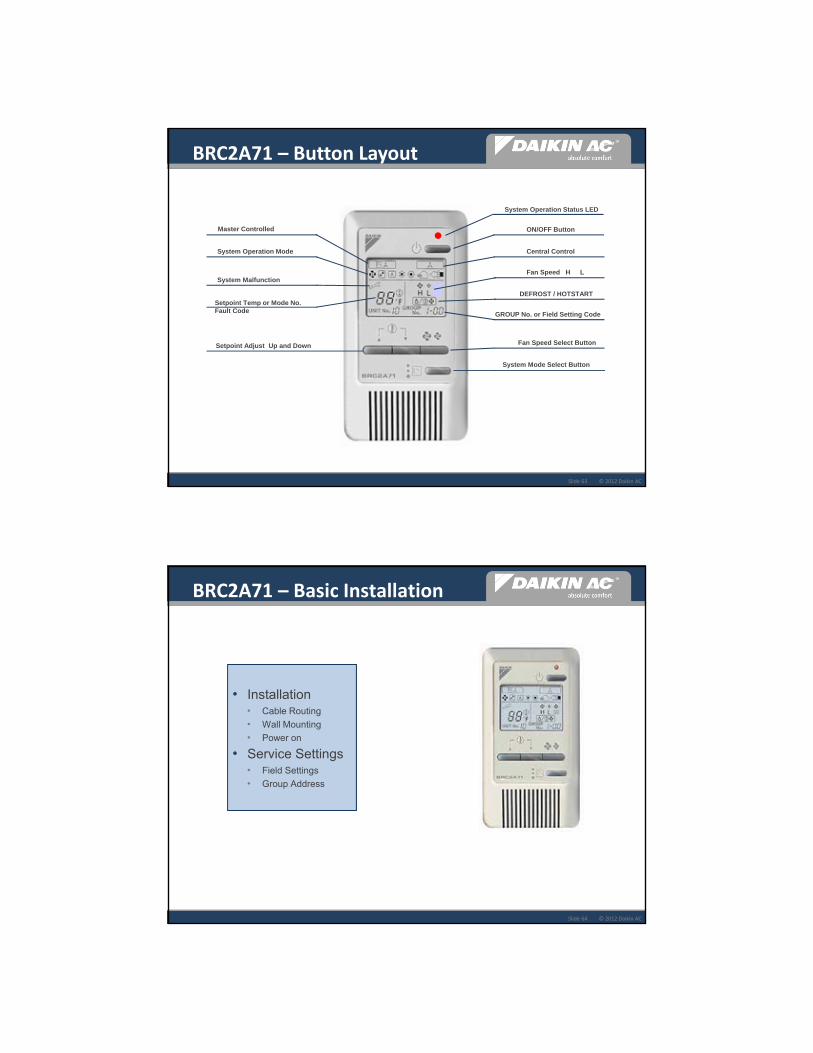
32
© 2012 Daikin ACSlide 63
System Operation Status LED
ON/OFF Button
Central Control
Fan Speed H L
DEFROST / HOTSTART
GROUP No. or Field Setting Code
Fan Speed Select Button
System Mode Select Button
Master Controlled
System Operation Mode
System Malfunction
Setpoint Temp or Mode No. Fault Code
Setpoint Adjust Up and Down
BRC2A71 – Button Layout
© 2012 Daikin ACSlide 64
• Installation• Cable Routing
• Wall Mounting
• Power on
• Service Settings• Field Settings
• Group Address
BRC2A71 – Basic Installation

33
© 2012 Daikin ACSlide 65
• Separate and remove the upper part of the controller with a flat blade screwdriver
• Carefully route the control wire from the P1 P2 terminals
• Secure the Lower part of the controller to the electrical box with the screws provided
• Install cover onto the lower part and insure that all buttons operate.
• Cover must be removed for all Service Settings
Electrical Box Field Supplied
Electrical Box Field Supplied
4
BRC2A71 – Mounting
© 2012 Daikin ACSlide 66
You can physically remove unnecessary buttons with optional face plates
No Modebutton
No Fan Speedbutton
All ButtonsAvailable
BRC2A71RU BRC2A71RBRC2A71RS
BRC2A71
BRC2A71 – Optional Face Plates

34
© 2012 Daikin ACSlide 67
BRC2A71 – Field Settings
• Remove cover from the controller• Press BS6 Button to enter Field Settings• Press BS2 and BS3 to select the Mode No.
• With multiple indoor units press BS8 to change Unit No.
• Press BS9 to select the First Code No.• Press BS10 for the Second Code No.• Press BS7 to Set the field Setting code• Press BS6 to confirm (88) and return to
Normal Display
© 2012 Daikin ACSlide 68
• Press BS6 to enter Group Address Mode• 00 display for Centralized Controller
• 01 display for no Centralized Controller
• GROUP No. flashing with 1-00 Group Address displayed• Press BS7 if Group No. is not flashing
• Press BS9 & BS10 to set desired address – Max. 64• 1-00 to 1-15
• 2-00 to 2-15
• 3-00 to 3-15
• 4-00 to 4-15
• Press BS7 to lock in selection• GROUP No. on solid
• Press BS6 to exit to normal display
BRC2A71 – Group Address
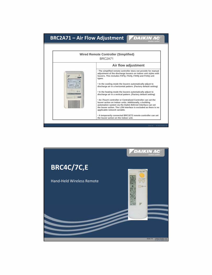
35
© 2012 Daikin ACSlide 69
Wired Remote Controller (Simplified)BRC2A71
Air flow adjustment
• The simplified remote controller does not provide for manual adjustment of the discharge louvers on indoor unit styles with louvers. This includes FXFQ, FXZQ, FXHQ and FXAQ unit types.
• In the cooling mode the louvers automatically adjust to discharge air in a horizontal pattern. (Factory default setting)
• In the heating mode the louvers automatically adjust to discharge air in a vertical pattern. (Factory default setting)
• An iTouch controller or Centralized Controller can set the louver action on indoor units. Additionally, a building automation system via the Daikin BACnet Interface can set the louver action. The LON Interface is excluded as there is no applicable network variable.
• A temporarily connected BRC1E72 remote controller can set the louver action on the indoor unit.
BRC2A71 – Air Flow Adjustment
© 2012 Daikin ACSlide 70 ©2012 Daikin AC
BRC4C/7C,E
Hand‐Held Wireless Remote
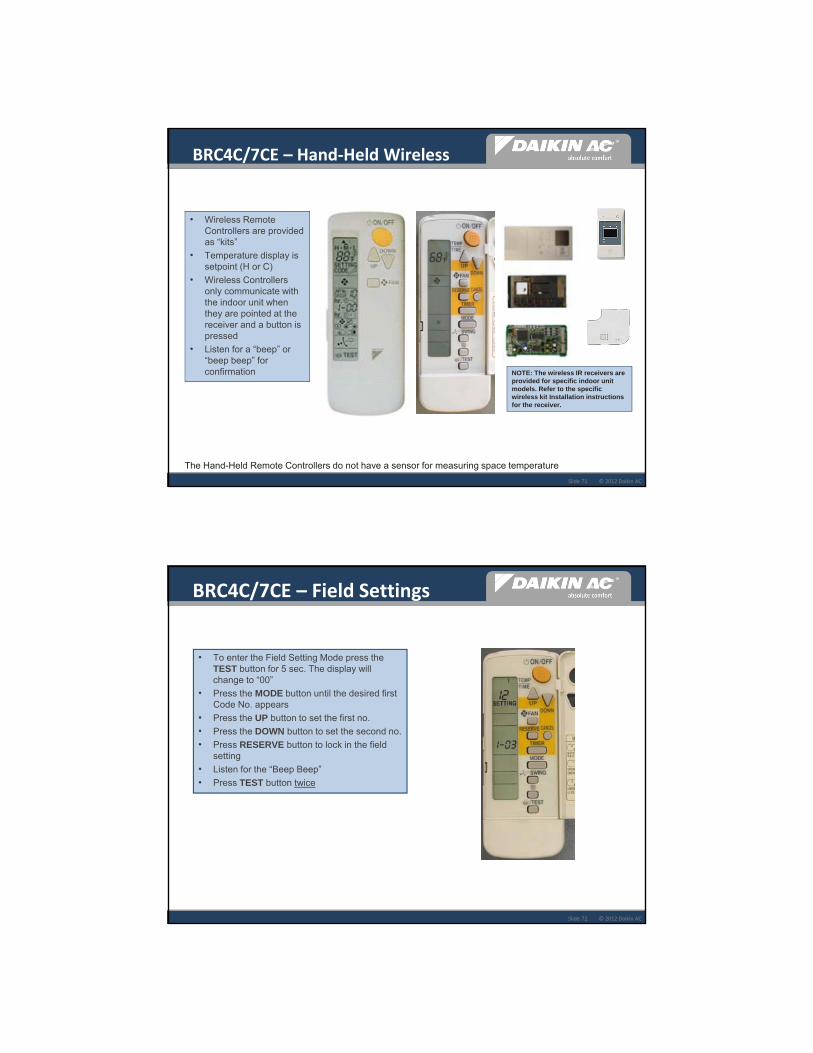
36
© 2012 Daikin ACSlide 71
BRC4C/7CE – Hand‐Held Wireless
• Wireless Remote Controllers are provided as “kits”
• Temperature display is setpoint (H or C)
• Wireless Controllers only communicate with the indoor unit when they are pointed at the receiver and a button is pressed
• Listen for a “beep” or “beep beep” for confirmation
The Hand-Held Remote Controllers do not have a sensor for measuring space temperature
NOTE: The wireless IR receivers are provided for specific indoor unit models. Refer to the specific wireless kit Installation instructions for the receiver.
© 2012 Daikin ACSlide 72
• To enter the Field Setting Mode press the TEST button for 5 sec. The display will change to “00”
• Press the MODE button until the desired first Code No. appears
• Press the UP button to set the first no.
• Press the DOWN button to set the second no.
• Press RESERVE button to lock in the field setting
• Listen for the “Beep Beep”
• Press TEST button twice
BRC4C/7CE – Field Settings
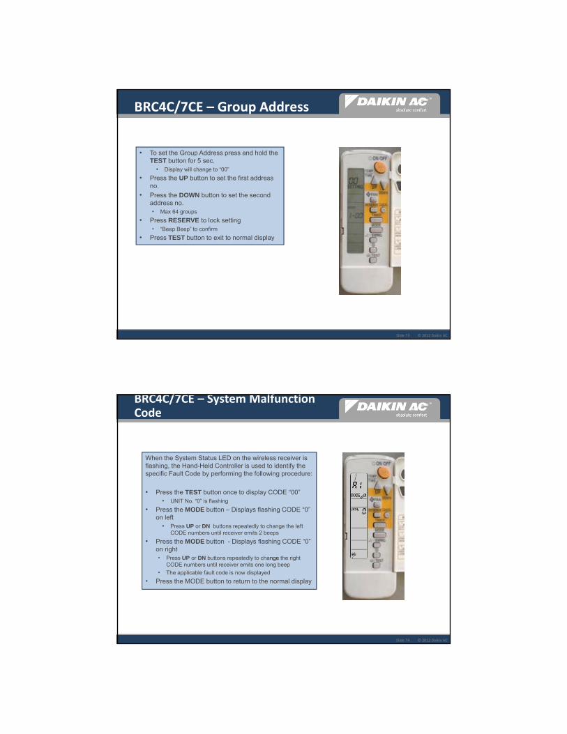
37
© 2012 Daikin ACSlide 73
• To set the Group Address press and hold the TEST button for 5 sec.
• Display will change to “00”
• Press the UP button to set the first address no.
• Press the DOWN button to set the second address no.• Max 64 groups
• Press RESERVE to lock setting• “Beep Beep” to confirm
• Press TEST button to exit to normal display
BRC4C/7CE – Group Address
© 2012 Daikin ACSlide 74
When the System Status LED on the wireless receiver is flashing, the Hand-Held Controller is used to identify the specific Fault Code by performing the following procedure:
• Press the TEST button once to display CODE “00”• UNIT No. “0” is flashing
• Press the MODE button – Displays flashing CODE “0” on left
• Press UP or DN buttons repeatedly to change the left CODE numbers until receiver emits 2 beeps
• Press the MODE button - Displays flashing CODE “0” on right• Press UP or DN buttons repeatedly to change the right
CODE numbers until receiver emits one long beep
• The applicable fault code is now displayed
• Press the MODE button to return to the normal display
BRC4C/7CE – System Malfunction Code

38
© 2012 Daikin AC
A designated Remote Controller must be configured as the Changeover Master in a Heat Pump system, or in a Heat Recovery system where a Branch Selector Box is connected to multiple indoor units controlled by individual Remote Controllers.
DIII‐Net System Control
Setting the Changeover Master
© 2012 Daikin ACSlide 76
• To configure a BRC1E72 (NAV Remote) as a Master on a new system: • Press any button to bring on the display
back light
• The icon will be flashing on all NAV remote controllers
• Press the Mode button once and the icon will disappear on the Master RC
• All other NAV Remote Controllers (slaves) will display solid
• To configure a BRC2A71 (Simplified)• The Master Controlled symbol will
be flashing (“Changeover Under Control”) on all Simplified RC’s
• Press the Mode button once and the symbol will disappear on the Master RC
• All other “Simplified” Slave Remote Controllers will display solid
• To change the Master, press & hold the Mode button for 5 sec. on the Master RC All RC’s go into Master configuration mode with flashing icons
BRC2A71 Simplified Remote
Controller
MASTER MASTER
7
DIII‐Net – Configure Remote Controller Changeover Master
BRC1E72 Navigation Remote
Controller

39
© 2012 Daikin ACSlide 77
Wireless Hand-Held Remote Controller
• On power up of indoor units, all “Master Controlled” icons or symbols will be flashing on the wired Controllers ONLY. The wireless Controllers do not display an icon for Master
• Go to the wireless Controller you want set as the Changeover Master and while pointing the wireless Controller at the indoor unit receiver:• Press and hold the MODE button for approx. 4 seconds - you will
hear “BEEP-BEEP” then a second “BEEP-BEEP”
• Press the MODE button a second time and listen for a “BEEP-BEEP” again; this is the confirmation that you have configured this indoor unit Remote Controller as the system Master
• To change the Master to a different Remote Controller in the system• Press and HOLD the MODE button for 4 seconds until “BEEP-
BEEP”
• Go to the new Remote Controller and press the MODE button once to set the MASTER
DIII‐Net – Configure Wireless Hand‐Held Remote Controller Changeover Master
© 2012 Daikin ACSlide 78Slide 78 ©2012 Daikin AC
Refer to the specific Remote Controller model Installation and Operation Manuals for more information.
Indoor Unit Field Setting codes are found in both the specific indoor unit Installation Manuals, and Condenser Service Manuals - Indoor Unit sections.
All VRV and SkyAir system components must be correctly wired using the Daikin specified control wire and installation practices to insure reliable system communications and control operation.
Additional Controls Training: http//daikinuniversity.comControls Product & ApplicationControls Installation & Commissioning Controls Integrator
DIII‐Net Remote Controller Additional Information

40
© 2012 Daikin AC
Thank YouPT-VRV-0113-PP0-01A

- 1 -
Field Settings for Daikin VRV / SkyAir indoor unit and BRC1E72
Control Engineering, Daikin AC (Americas)
7/31/2013 Availability of Indoor Unit Field Settings (Control Related) As of 7/31/2013
Mode No. 10 12 First Code No. 2 5 6 0 1 2 (****) 3 6 8 Second Code No. 01/02 03 01/02 01/02 01/03/04 01/02/03 01/02 01/02 03 01/02/03 01/02 FXSQ_MVJU X X*** X*** X X X X (02) X X*** X** n/a FXMQ_MVJU X X** X** X X X X (02) X X** X** n/a FXMQ72/96MVJU X X X X X X X (02) X X X n/a FXMQ_PVJU FBQ_PVJU X X X X X X X (02) X X X n/a
FXDQ_MVJU X X X X X X X (02) X X X * n/a FXTQ_PVJU FTQ_PAVJU FTQ_PBVJU
X X X X X X X (02) X X X n/a
BEQ_MVJLR1 (FXOQ) X X X X X X X (02) X X X** n/a
FXLQ_MVJU X X** X** X X X X (02) X X** X** n/a FXNQ_MVJU X X** X** X X X X (02) X X** X** n/a FXAQ_MVJU FAQ_MVJU FAQ_PVJU
X X** X** X n/a X X (01) X X** n/a n/a
FXAQ_PVJU X X X X n/a X X (01) X X n/a n/a FXZQ_M7VJU X X** X** X X X X (01) X X** X** n/a FXFQ_MVJU FCQ_MVJU FCQ_PVJU
X n/a n/a n/a X X X (01) X n/a n/a n/a
FXFQ_PVJU FCQ_PAVJU X X X X X X X (01) X X X X
FXHQ_MVJU FHQ_MVJU FHQ_PVJU
X n/a n/a n/a X X X (01) X n/a n/a n/a
* Field settings highlighted in purple may not be available in units manufactured before 1/1/2013. ** Field settings highlighted in orange may not be available in units manufactured before 9/1/2009. *** Field settings highlighted in blue may not be available in units manufactured before 1/1/2007. **** Factory default value is indicated in parenthesis.

- 2 - Field Settings – Indoor Units (Control Related) Mode No. (Note 1)
First Code No.
Description Second Code No. (Note 2) (Cells in bold are factory default settings) 01 02 03 04
10(20) 2 Priority of thermistor sensors for space temperature control
The return air thermistor is primary and the remote controller thermistor Is secondary.
Only the return air thermistor will be utilized.
Only the remote controller thermistor will be utilized.
--
5 Room temperature value reported to multizone controllers
Return air thermistor Thermistor designated by 10-2 above (Note 3)
-- --
6 The remote controller thermistor is used in Remote Controller Group
No Yes -- --
12(22) 0
KRP1B71 X1-X2 status output
Indoor unit Thermo-On/Off status
-- Indoor unit Operation On/Off status
Indoor unit Alarm status
1 Indoor unit T1-T2 input
Forced Off Closed Contact-Indoor unit is forced off and Central Control icon is displayed. Unit cannot be turned on manually. Operation can be overridden by central control. Open Contact-Indoor unit can resume normal operation. Unit must be turned on manually or by central control.
On/Off Closed Contact-Indoor unit is turned on. Open Contact-Indoor unit is turned off. Unit responds to last command, i.e., unit can be turned on manually or by central control after circuit has opened. Operation is prohibited when remote controller On/Off control is restricted by a multizone controller.
External Protection Device Closed contact-Unit shall resume normal operation. Open contact-Unit shall shut down and generate an A0 error.
2 Thermo-On/Off deadband (Note 4)
2F (1C) 1F (0.5C) -- --
3 Fan Speed in Heating Thermo-Off
LL User set Off --
6 Fan Speed in Cooling Thermo-Off
LL User set Off --
8 Return air sensor offset
2C None (for remote sensor)
1. Field settings are normally applied to the entire remote control group, however if individual indoor units in the
remote control group require specific settings or for confirmation that settings have been established, utilize the mode number in parenthesis.
2. Any features not supported by the installed indoor unit will not be displayed. 3. When mode 10-2-01 is selected, only the return air temperature value is reported to the multizone controller. 4. The actual default deadband value will depend upon the indoor unit model.

- 3 - Field Settings – BRC1E72 (Green highlighted items are new from BRC1E71)
Mode No. First
Code No.
Description Second Code No. (Cells in bold are factory default settings) 01 02 03 04
1b 7 STANDBY icon Display in Defrost or Hot Start
Not Displayed
11 Day/Clock Displayed Not Displayed
12 Setpoint display while the unit is off
Displayed Not Displayed
13 Mode display while the unit is off
Displayed Display OFF instead of the mode
14 Fan Speed button configuration
Fan Speed Fan ON/Auto (Fan LL in thermo-off) (Applicable to SkyAir only)
FAN ON/Auto (Fan Off in thermo-off) (Applicable to SkyAir only)
15 Fan icon display Displayed Not Displayed
1c 1 Thermistor sensor used for Auto-changeover and Setback control
Return Air Thermistor–return air temperature displayed on controller as room temperature
Remote Controller Thermistor – remote controller temperature displayed on controller as room temperature
-- --
10 Temperature Sensor Offset
01: -5.4oF (-3.0oC)
02: -4.5oF (-2.5oC)
03: -3.6oF (-2.0oC)
04: -2.7oF (-1.5oC)
05: -1.8oF (-1.0oC)
06: -0.9oF (-0.5oC)
07: 0.0oF (0.0oC)
13: +5.4oF (+3.0oC)
12: +4.5oF (+2.5oC)
11: +3.6oF (+2.0oC)
10: +2.7oF (+1.5oC)
09:+1.8oF (+1.0oC)
08:+0.9oF (+0.5oC)
1e 2 Setback availability
N/A Heating mode only Cooling mode only
Cooling/ Heating modes
4 Schedule and Auto-changeover enabled when multizone controller is detected (Note 1)
No Yes -- --
9 CENTRAL CONTROL icon
Not displayed Displayed when under control by a multizone controller
10 Message when button pushed which has been prohibited by a multizone controller
Key lock icon blinks for 5 seconds
Message displayed on screen: “Under Centralized Control. Adjustments at the remote control are being restricted.”
11 Auto changeover guard timer
15 min 30 min 60 min 90 min
12 Auto changeover point
0.9 oF (0.5 oC) 1.8oF (1.0 oC) 2.7oF (1.5oC) 3.6oF (2.0oC)
13 Quick changeover point beyond the auto changeover point
0.9 oF (0.5 oC) 1.8oF (1.0 oC) 2.7oF (1.5oC) 3.6oF (2.0oC)
1. Native remote controller Schedule and Auto-changeover functions are disabled when a multizone controller is
detected and a group address is assigned.
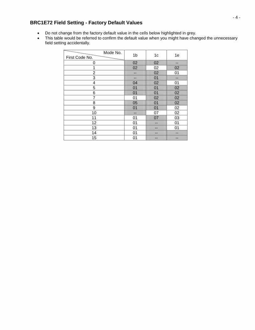
- 4 - BRC1E72 Field Setting - Factory Default Values
• Do not change from the factory default value in the cells below highlighted in grey. • This table would be referred to confirm the default value when you might have changed the unnecessary
field setting accidentally.
Mode No. First Code No. 1b 1c 1e
0 02 02 -- 1 02 02 02 2 -- 02 01 3 -- 01 -- 4 04 02 01 5 01 01 02 6 01 01 02 7 01 02 02 8 05 01 02 9 01 01 02 10 -- 07 02 11 01 07 03 12 01 -- 01 13 01 -- 01 14 01 -- -- 15 01 -- --