VRV VRV-S Indoor Units Guide Spec - Intellichoice...
29
Daikin North America LLC – VRV/S Indoor Units WGSVI0314 Daikin AC HVAC Guide Specifications Multiple Evaporator, Direct Expansion (DX), Air-Cooled, Variable Capacity, Split System Section 15700 – Mechanical HVAC Size Range: 0.6 to 8 Tons Nominal Daikin AC Model Number: FXFQ_T INDOOR UNIT – ROUND FLOW SENSING CEILING CASSETTE UNIT FXZQ INDOOR UNIT – 4 WAY CEILING CASSETTE UNIT (2’x2’) FXMQ_M INDOOR UNIT – CONCEALED CEILING DUCTED UNIT (Med. Static) FXMQ_PA INDOOR UNIT – CONCEALED CEILING DUCTED UNIT (Med. Static) FXDQ INDOOR UNIT – SLIM DUCT CONCEALED CEILING UNIT FXHQ INDOOR UNIT – CEILING SUSPENDED CASSETTE UNIT FXAQ INDOOR UNIT – WALL MOUNTED UNIT FXLQ INDOOR UNIT – FLOOR CONSOLE UNIT FXNQ INDOOR UNIT – FLOOR CONSOLE CONCEALED UNIT FXTQ INDOOR UNIT – VERTICAL AIR HANDLING UNIT FXMQ_MF INDOOR UNIT – OUTSIDE AIR PROCESSING UNIT Part 1 – GENERAL VARIABLE REFRIGERANT VOLUME (VRV / VRV-S) AIR CONDITIONING SPECIFICATION – Heat Recovery/Heat Pump Indoor Units 1.01 QUALITY ASSURANCE A. The units shall be tested by a Nationally Recognized Testing Laboratory (NRTL), in accordance with ANSI/UL 1995/CAN/CSA-C22.2 No. 236-05 (R2009) – Heating and Cooling Equipment and bear the Listed Mark. B. All wiring shall be in accordance with the National Electric Code (NEC)/Canadian Electrical Code (CEC). C. The system will be produced in an ISO 9001 and ISO 14001 facility, which are standards set by the International Standard Organization (ISO). The system shall be factory tested for safety and function. D. The outdoor unit will be factory charged with R-410A. 1.02 DELIVERY, STORAGE AND HANDLING A. Unit shall be stored and handled according to the manufacturer’s recommendations.
Transcript of VRV VRV-S Indoor Units Guide Spec - Intellichoice...
Daikin North America LLC – VRV/S Indoor Units WGSVI0314
Daikin AC
HVAC Guide Specifications Multiple Evaporator, Direct Expansion (DX), Air-Cooled, Variable Capacity, Split System Section 15700 – Mechanical HVAC Size Range:
0.6 to 8 Tons Nominal Daikin AC Model Number: FXFQ_T INDOOR UNIT – ROUND FLOW SENSING CEILING CASSETTE UNIT FXZQ INDOOR UNIT – 4 WAY CEILING CASSETTE UNIT (2’x2’) FXMQ_M INDOOR UNIT – CONCEALED CEILING DUCTED UNIT (Med. Static) FXMQ_PA INDOOR UNIT – CONCEALED CEILING DUCTED UNIT (Med. Static)
FXDQ INDOOR UNIT – SLIM DUCT CONCEALED CEILING UNIT FXHQ INDOOR UNIT – CEILING SUSPENDED CASSETTE UNIT FXAQ INDOOR UNIT – WALL MOUNTED UNIT
FXLQ INDOOR UNIT – FLOOR CONSOLE UNIT FXNQ INDOOR UNIT – FLOOR CONSOLE CONCEALED UNIT FXTQ INDOOR UNIT – VERTICAL AIR HANDLING UNIT FXMQ_MF INDOOR UNIT – OUTSIDE AIR PROCESSING UNIT Part 1 – GENERAL VARIABLE REFRIGERANT VOLUME (VRV / VRV-S) AIR CONDITIONING SPECIFICATION – Heat Recovery/Heat Pump Indoor Units
1.01 QUALITY ASSURANCE
A. The units shall be tested by a Nationally Recognized Testing Laboratory (NRTL), in accordance with ANSI/UL 1995/CAN/CSA-C22.2 No. 236-05 (R2009) – Heating and Cooling Equipment and bear the Listed Mark.
B. All wiring shall be in accordance with the National Electric Code (NEC)/Canadian Electrical Code (CEC).
C. The system will be produced in an ISO 9001 and ISO 14001 facility, which are standards set by the International Standard Organization (ISO). The system shall be factory tested for safety and function.
D. The outdoor unit will be factory charged with R-410A. 1.02 DELIVERY, STORAGE AND HANDLING
A. Unit shall be stored and handled according to the manufacturer’s recommendations.
Daikin North America LLC – VRV/S Indoor Units WGSVI0314
Part 3 – PERFORMANCE
3.01 DESIGN BASIS
The HVAC equipment basis of design is Daikin. All bidders shall furnish the minimum system standards as defined by the base bid model numbers, model families or as otherwise specified herein (see Key General Specifications Alternate Supplier Checklist). In any event the contractor shall be responsible for all specified items and intents of this document without further compensation.
Part 4 – PRODUCTS 4.01 FXFQ_T – ROUND FLOW SENSING CEILING CASSETTE UNIT
A. General: Daikin indoor unit model FXFQ_T shall be a round flow ceiling cassette fan coil unit, operable with R-410A refrigerant, equipped with an electronic expansion valve, direct drive DC (ECM) type fan, for installation into the ceiling cavity equipped with an air panel grill. It shall be available in capacities from 7,500 Btu/h to 48,000 Btu/h. Model numbers are FXFQ07TVJU, FXFQ09TVJU, FXFQ12TVJU, FXFQ15TVJU , FXFQ18TVJU, FXFQ24TVJU, FXFQ30TVJU, FXFQ36TVJU, FXFQ48TVJU to be connected to outdoor unit model RXYQ / RXYMQ / RWEYQ heat pump and REYQ / RWEYQ heat recovery model. It shall be a round flow air distribution type, fresh white, impact resistant decoration panel, or optional self-cleaning filter panel. The supply air is distributed via four individually motorized louvers. To save energy and optimize occupancy comfort, the indoor unit shall be equipped with built in occupancy sensor and surface temperature sensor. Computerized PID control shall be used to control superheat to deliver a comfortable room temperature condition. The unit shall be equipped with a programmed drying mechanism that dehumidifies while limiting changes in room temperature when used with Daikin remote control BRC1E72, BRC2A71 and BRC1E52B7. The indoor units sound pressure shall range from 30 dB(A) to 45 dB(A) at High speed measured at 5 feet below the unit.
Daikin North America LLC – VRV/S Indoor Units WGSVI0314
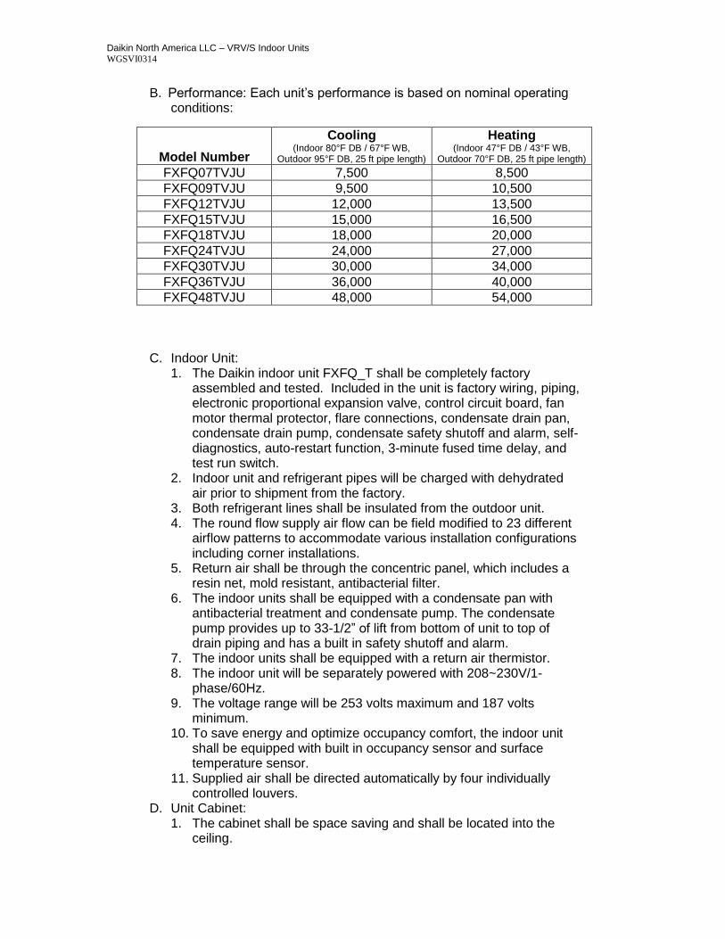
B. Performance: Each unit’s performance is based on nominal operating conditions:
C. Indoor Unit: 1. The Daikin indoor unit FXFQ_T shall be completely factory
assembled and tested. Included in the unit is factory wiring, piping, electronic proportional expansion valve, control circuit board, fan motor thermal protector, flare connections, condensate drain pan, condensate drain pump, condensate safety shutoff and alarm, self-diagnostics, auto-restart function, 3-minute fused time delay, and test run switch.
2. Indoor unit and refrigerant pipes will be charged with dehydrated air prior to shipment from the factory.
3. Both refrigerant lines shall be insulated from the outdoor unit. 4. The round flow supply air flow can be field modified to 23 different
airflow patterns to accommodate various installation configurations including corner installations.
5. Return air shall be through the concentric panel, which includes a resin net, mold resistant, antibacterial filter.
6. The indoor units shall be equipped with a condensate pan with antibacterial treatment and condensate pump. The condensate pump provides up to 33-1/2” of lift from bottom of unit to top of drain piping and has a built in safety shutoff and alarm.
7. The indoor units shall be equipped with a return air thermistor. 8. The indoor unit will be separately powered with 208~230V/1-
phase/60Hz. 9. The voltage range will be 253 volts maximum and 187 volts
minimum. 10. To save energy and optimize occupancy comfort, the indoor unit
shall be equipped with built in occupancy sensor and surface temperature sensor.
11. Supplied air shall be directed automatically by four individually controlled louvers.
D. Unit Cabinet: 1. The cabinet shall be space saving and shall be located into the
ceiling.
Model Number
Cooling (Indoor 80°F DB / 67°F WB,
Outdoor 95°F DB, 25 ft pipe length)
Heating (Indoor 47°F DB / 43°F WB,
Outdoor 70°F DB, 25 ft pipe length)
FXFQ07TVJU 7,500 8,500
FXFQ09TVJU 9,500 10,500
FXFQ12TVJU 12,000 13,500
FXFQ15TVJU 15,000 16,500
FXFQ18TVJU 18,000 20,000
FXFQ24TVJU 24,000 27,000
FXFQ30TVJU 30,000 34,000
FXFQ36TVJU 36,000 40,000
FXFQ48TVJU 48,000 54,000
Daikin North America LLC – VRV/S Indoor Units WGSVI0314
2. Four auto-adjusted louvers shall be available to choose, which include standard, draft prevention and ceiling stain prevention.
3. The airflow of the unit shall have the ability to shut down outlets with multiple patterns allowing for simpler installation in irregular spaces.
4. Fresh air intake shall be possible by way of Daikin’s optional fresh air intake kit.
5. A branch duct knockout shall exist for branch ducting of supply air. 6. The cabinet shall be constructed with sound absorbing foamed
polystyrene and polyethylene insulation. 7. Optional high efficiency air filters are available for each model unit.
E. Fan: 1. The fan shall be direct-drive DC (ECM) type fan, statically and
dynamically balanced impeller with three fan speeds available. 2. The fan motor shall operate on 208/230 volts, 1 phase, 60 hertz
with a motor output range from 0.08 to 0.16 HP. 3. The airflow rate shall be available in three manual settings. 4. The DC fan shall be able to automatically adjust the fan speed in 5
speeds based on the space load. 5. The fan motor shall be equipped as standard with adjustable
external static pressure (ESP) settings to allow operation with the high efficiency air filter options.
6. The fan motor shall be thermally protected. F. Filter:
1. The return air shall be filtered by means of a washable long-life filter with mildew proof resin and antibacterial treatment.
2. Optional high efficiency disposable air filters shall be available. 3. Optional Self-Cleaning Filter Panel, which performs automatic filter
cleaning up to once a day, with dust collection box that indicates when to be emptied.
G. Coil: 1. Coils shall be of the direct expansion type constructed from copper
tubes expanded into aluminum fins to form a mechanical bond. 2. The coil shall be of a waffle louver fin and high heat exchange,
rifled bore tube design to ensure highly efficient performance. 3. The coil shall be a 2, or 3-row cross fin copper evaporator coil with
up to 21 FPI design completely factory tested. 4. The refrigerant connections shall be flare connections and the
condensate will be 1 -1/4 inch outside diameter PVC. 5. A condensate pan with antibacterial treatment shall be located
under the coil. 6. A thermistor will be located on the liquid and gas line.
H. Electrical: 1. A separate power supply will be required of 208/230 volts, 1 phase,
60 hertz. The acceptable voltage range shall be 187 to 253 volts. 2. Transmission (control) wiring between the indoor and outdoor unit
shall be a maximum of 3,280 feet (total 6,560 feet). 3. Transmission (control) wiring between the indoor unit and remote
controller shall be a maximum distance of 1,640 feet.
Daikin North America LLC – VRV/S Indoor Units WGSVI0314
I. Control: 1. The unit shall have controls provided by Daikin to perform input
functions necessary to operate the system. 2. The unit shall be compatible with interfacing with a BMS system via
optional LonWorks or BACnet gateways. 3. The unit shall be compatible with a Daikin Intelligent Touch
Manager advanced multi-zone controller. 4. For the Sensing functions and the optional Self-Cleaning Filter
functions, Remote controller BRC1E52B7 shall be used. Consult with Daikin prior to applying controls.
J. Optional Accessories Available: 1. A high efficiency disposable air filter kit. 2. Air intake kit . 3. Self-Cleaning Filter Panel, which performs automatic filter cleaning
up to once a day, with dust collection box that indicates when to be emptied.
4. Remote “in-room” sensor kit (KRCS01-4B). i. The Daikin wall mounted, hard wired remote sensor kit is
recommended for when a NAV controller is not used or when the NAV controller is not located in the space that is being controlled. The sensor for detecting the temperature can be placed away from the indoor unit (branch wiring is included in the kit).
4.02 FXZQ – 4 WAY CEILING CASSETTE UNIT (2’x2’)
A. General: Daikin indoor unit model FXZQ shall be a ceiling cassette fan coil unit, operable with R-410A refrigerant, equipped with an electronic expansion valve, for installation into the ceiling cavity equipped with an air panel grill. It shall be available in capacities from 7,500 Btu/h to 18,000 Btu/h. Model numbers are FXZQ07MVJU9, FXZQ09MVJU9, FXZQ12MVJU9, FXZQ15MVJU9, FXZQ18MVJU9 to be connected to outdoor unit model RXYQ / RXYMQ / RWEYQ heat pump and REYQ / RWEYQ heat recovery model. It shall be a four-way air distribution type, white (RAL9010), impact resistant with a washable decoration panel. The supply air is distributed via motorized louvers which can be horizontally and vertically adjusted from 0° to 90°. Computerized PID control shall be used to control superheat to deliver a comfortable room temperature condition. The unit shall be equipped with a programmed drying mechanism that dehumidifies while limiting changes in room temperature when used with Daikin remote control BRC1E72 and BRC2A71. The indoor units sound pressure shall range from 29 dB(A) to 34 dB(A) at low speed measured at 5 feet below the unit.
Daikin North America LLC – VRV/S Indoor Units WGSVI0314
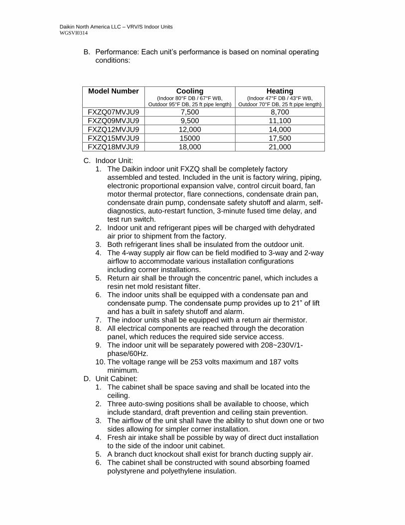
B. Performance: Each unit’s performance is based on nominal operating conditions:
C. Indoor Unit: 1. The Daikin indoor unit FXZQ shall be completely factory
assembled and tested. Included in the unit is factory wiring, piping, electronic proportional expansion valve, control circuit board, fan motor thermal protector, flare connections, condensate drain pan, condensate drain pump, condensate safety shutoff and alarm, self-diagnostics, auto-restart function, 3-minute fused time delay, and test run switch.
2. Indoor unit and refrigerant pipes will be charged with dehydrated air prior to shipment from the factory.
3. Both refrigerant lines shall be insulated from the outdoor unit. 4. The 4-way supply air flow can be field modified to 3-way and 2-way
airflow to accommodate various installation configurations including corner installations.
5. Return air shall be through the concentric panel, which includes a resin net mold resistant filter.
6. The indoor units shall be equipped with a condensate pan and condensate pump. The condensate pump provides up to 21” of lift and has a built in safety shutoff and alarm.
7. The indoor units shall be equipped with a return air thermistor. 8. All electrical components are reached through the decoration
panel, which reduces the required side service access. 9. The indoor unit will be separately powered with 208~230V/1-
phase/60Hz. 10. The voltage range will be 253 volts maximum and 187 volts
minimum. D. Unit Cabinet:
1. The cabinet shall be space saving and shall be located into the ceiling.
2. Three auto-swing positions shall be available to choose, which include standard, draft prevention and ceiling stain prevention.
3. The airflow of the unit shall have the ability to shut down one or two sides allowing for simpler corner installation.
4. Fresh air intake shall be possible by way of direct duct installation to the side of the indoor unit cabinet.
5. A branch duct knockout shall exist for branch ducting supply air. 6. The cabinet shall be constructed with sound absorbing foamed
polystyrene and polyethylene insulation.
Model Number Cooling (Indoor 80°F DB / 67°F WB,
Outdoor 95°F DB, 25 ft pipe length)
Heating (Indoor 47°F DB / 43°F WB,
Outdoor 70°F DB, 25 ft pipe length)
FXZQ07MVJU9 7,500 8,700
FXZQ09MVJU9 9,500 11,100
FXZQ12MVJU9 12,000 14,000
FXZQ15MVJU9 15000 17,500
FXZQ18MVJU9 18,000 21,000
Daikin North America LLC – VRV/S Indoor Units WGSVI0314
E. Fan: 1. The fan shall be direct-drive turbo fan type with statically and
dynamically balanced impeller with high and low fan speeds available.
2. The fan motor shall operate on 208/230 volts, 1 phase, 60 hertz with a motor output range from 0.06 to 0.12 HP.
3. The airflow rate shall be available in high and low settings. 4. The fan motor shall be thermally protected.
F. Filter: 1. The return air shall be filtered by means of a washable long-life
filter with mildew proof resin. G. Coil:
1. Coils shall be of the direct expansion type constructed from copper tubes expanded into aluminum fins to form a mechanical bond.
2. The coil shall be of a waffle louver fin and high heat exchange, rifled bore tube design to ensure highly efficient performance.
3. The coil shall be a 2-row cross fin copper evaporator coil with 17 FPI design completely factory tested.
4. The refrigerant connections shall be flare connections and the condensate will be 1 -1/32 inch outside diameter PVC.
5. A condensate pan shall be located under the coil. 6. A condensate pump with a 21 inch lift shall be located below the
coil in the condensate pan with a built in safety alarm. 7. A thermistor will be located on the liquid and gas line.
H. Electrical: 1. A separate power supply will be required of 208/230 volts, 1 phase,
60 hertz. The acceptable voltage range shall be 187 to 253 volts. 2. Transmission (control) wiring between the indoor and outdoor unit
shall be a maximum of 3,280 feet (total 6,560 feet). 3. Transmission (control) wiring between the indoor unit and remote
controller shall be a maximum distance of 1,640 feet. I. Control:
1. The unit shall have controls provided by Daikin to perform input functions necessary to operate the system.
2. The unit shall be compatible with interfacing with a BMS system via optional LonWorks or BACnet gateways.
3. The unit shall be compatible with a Daikin Intelligent Touch Manager advanced multi-zone controller.
J. Optional Accessories Available: 1. Direct fresh air intake kit (KDDQ44X60). 2. Supply air duct connections. 3. Remote “in-room” sensor kit (KRCS01-1B).
i. The Daikin wall mounted, hard wired remote sensor kit is recommended for ceiling-embedded type fan coils, which often result in a difference between set temperature and actual temperature. The sensor for detecting the temperature can be placed away from the indoor unit (branch wiring is included in the kit).
Daikin North America LLC – VRV/S Indoor Units WGSVI0314
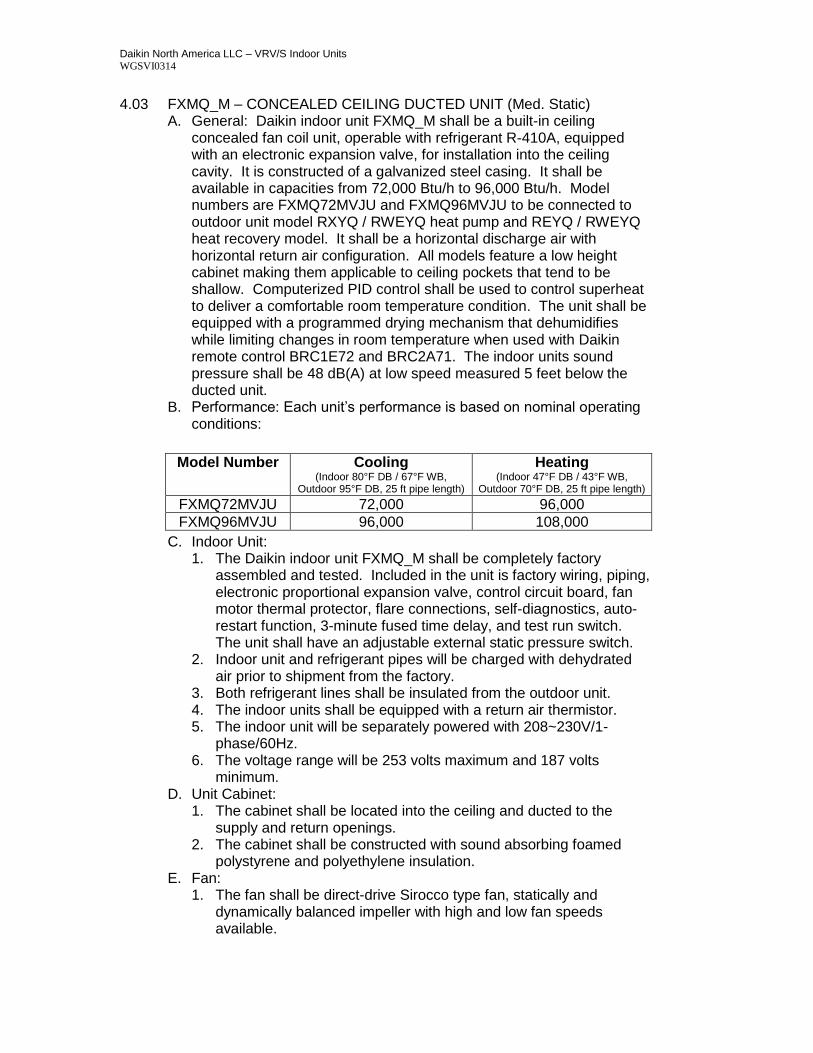
4.03 FXMQ_M – CONCEALED CEILING DUCTED UNIT (Med. Static) A. General: Daikin indoor unit FXMQ_M shall be a built-in ceiling
concealed fan coil unit, operable with refrigerant R-410A, equipped with an electronic expansion valve, for installation into the ceiling cavity. It is constructed of a galvanized steel casing. It shall be available in capacities from 72,000 Btu/h to 96,000 Btu/h. Model numbers are FXMQ72MVJU and FXMQ96MVJU to be connected to outdoor unit model RXYQ / RWEYQ heat pump and REYQ / RWEYQ heat recovery model. It shall be a horizontal discharge air with horizontal return air configuration. All models feature a low height cabinet making them applicable to ceiling pockets that tend to be shallow. Computerized PID control shall be used to control superheat to deliver a comfortable room temperature condition. The unit shall be equipped with a programmed drying mechanism that dehumidifies while limiting changes in room temperature when used with Daikin remote control BRC1E72 and BRC2A71. The indoor units sound pressure shall be 48 dB(A) at low speed measured 5 feet below the ducted unit.
B. Performance: Each unit’s performance is based on nominal operating conditions:
C. Indoor Unit: 1. The Daikin indoor unit FXMQ_M shall be completely factory
assembled and tested. Included in the unit is factory wiring, piping, electronic proportional expansion valve, control circuit board, fan motor thermal protector, flare connections, self-diagnostics, auto-restart function, 3-minute fused time delay, and test run switch. The unit shall have an adjustable external static pressure switch.
2. Indoor unit and refrigerant pipes will be charged with dehydrated air prior to shipment from the factory.
3. Both refrigerant lines shall be insulated from the outdoor unit. 4. The indoor units shall be equipped with a return air thermistor. 5. The indoor unit will be separately powered with 208~230V/1-
phase/60Hz. 6. The voltage range will be 253 volts maximum and 187 volts
minimum. D. Unit Cabinet:
1. The cabinet shall be located into the ceiling and ducted to the supply and return openings.
2. The cabinet shall be constructed with sound absorbing foamed polystyrene and polyethylene insulation.
E. Fan: 1. The fan shall be direct-drive Sirocco type fan, statically and
dynamically balanced impeller with high and low fan speeds available.
Model Number Cooling (Indoor 80°F DB / 67°F WB,
Outdoor 95°F DB, 25 ft pipe length)
Heating (Indoor 47°F DB / 43°F WB,
Outdoor 70°F DB, 25 ft pipe length) FXMQ72MVJU 72,000 96,000
FXMQ96MVJU 96,000 108,000
Daikin North America LLC – VRV/S Indoor Units WGSVI0314
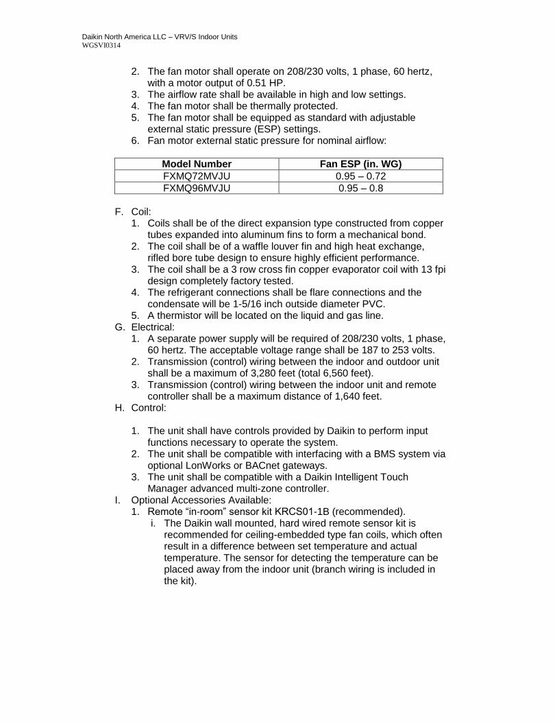
2. The fan motor shall operate on 208/230 volts, 1 phase, 60 hertz, with a motor output of 0.51 HP.
3. The airflow rate shall be available in high and low settings. 4. The fan motor shall be thermally protected. 5. The fan motor shall be equipped as standard with adjustable
external static pressure (ESP) settings. 6. Fan motor external static pressure for nominal airflow:
Model Number Fan ESP (in. WG)
FXMQ72MVJU 0.95 – 0.72
FXMQ96MVJU 0.95 – 0.8
F. Coil:
1. Coils shall be of the direct expansion type constructed from copper tubes expanded into aluminum fins to form a mechanical bond.
2. The coil shall be of a waffle louver fin and high heat exchange, rifled bore tube design to ensure highly efficient performance.
3. The coil shall be a 3 row cross fin copper evaporator coil with 13 fpi design completely factory tested.
4. The refrigerant connections shall be flare connections and the condensate will be 1-5/16 inch outside diameter PVC.
5. A thermistor will be located on the liquid and gas line. G. Electrical:
1. A separate power supply will be required of 208/230 volts, 1 phase, 60 hertz. The acceptable voltage range shall be 187 to 253 volts.
2. Transmission (control) wiring between the indoor and outdoor unit shall be a maximum of 3,280 feet (total 6,560 feet).
3. Transmission (control) wiring between the indoor unit and remote controller shall be a maximum distance of 1,640 feet.
H. Control:
1. The unit shall have controls provided by Daikin to perform input functions necessary to operate the system.
2. The unit shall be compatible with interfacing with a BMS system via optional LonWorks or BACnet gateways.
3. The unit shall be compatible with a Daikin Intelligent Touch Manager advanced multi-zone controller.
I. Optional Accessories Available: 1. Remote “in-room” sensor kit KRCS01-1B (recommended).
i. The Daikin wall mounted, hard wired remote sensor kit is recommended for ceiling-embedded type fan coils, which often result in a difference between set temperature and actual temperature. The sensor for detecting the temperature can be placed away from the indoor unit (branch wiring is included in the kit).
Daikin North America LLC – VRV/S Indoor Units WGSVI0314
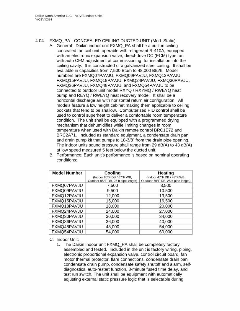
4.04 FXMQ_PA - CONCEALED CEILING DUCTED UNIT (Med. Static)
A. General: Daikin indoor unit FXMQ_PA shall be a built-in ceiling concealed fan coil unit, operable with refrigerant R-410A, equipped with an electronic expansion valve, direct-drive DC (ECM) type fan with auto CFM adjustment at commissioning, for installation into the ceiling cavity. It is constructed of a galvanized steel casing. It shall be available in capacities from 7,500 Btu/h to 48,000 Btu/h. Model numbers are FXMQ07PAVJU, FXMQ09PAVJU, FXMQ12PAVJU, FXMQ15PAVJU, FXMQ18PAVJU, FXMQ24PAVJU, FXMQ30PAVJU, FXMQ36PAVJU, FXMQ48PAVJU, and FXMQ54PAVJU to be connected to outdoor unit model RXYQ / RXYMQ / RWEYQ heat pump and REYQ / RWEYQ heat recovery model. It shall be a horizontal discharge air with horizontal return air configuration. All models feature a low height cabinet making them applicable to ceiling pockets that tend to be shallow. Computerized PID control shall be used to control superheat to deliver a comfortable room temperature condition. The unit shall be equipped with a programmed drying mechanism that dehumidifies while limiting changes in room temperature when used with Daikin remote control BRC1E72 and BRC2A71. Included as standard equipment, a condensate drain pan and drain pump kit that pumps to 18-3/8” from the drain pipe opening. The indoor units sound pressure shall range from 29 dB(A) to 43 dB(A) at low speed measured 5 feet below the ducted unit.
B. Performance: Each unit’s performance is based on nominal operating conditions:
C. Indoor Unit: 1. The Daikin indoor unit FXMQ_PA shall be completely factory
assembled and tested. Included in the unit is factory wiring, piping, electronic proportional expansion valve, control circuit board, fan motor thermal protector, flare connections, condensate drain pan, condensate drain pump, condensate safety shutoff and alarm, self-diagnostics, auto-restart function, 3-minute fused time delay, and test run switch. The unit shall be equipment with automatically adjusting external static pressure logic that is selectable during
Model Number Cooling (Indoor 80°F DB / 67°F WB,
Outdoor 95°F DB, 25 ft pipe length)
Heating (Indoor 47°F DB / 43°F WB,
Outdoor 70°F DB, 25 ft pipe length) FXMQ07PAVJU 7,500 8,500
FXMQ09PAVJU 9,500 10.500
FXMQ12PAVJU 12,000 13,500
FXMQ15PAVJU 15,000 16,500
FXMQ18PAVJU 18,000 20,000
FXMQ24PAVJU 24,000 27,000
FXMQ30PAVJU 30,000 34,000
FXMQ36PAVJU 36,000 40,000
FXMQ48PAVJU 48,000 54,000
FXMQ54PAVJU 54,000 60,000
Daikin North America LLC – VRV/S Indoor Units WGSVI0314
commissioning. This adjusts the airflow based on the installed external static pressure.
2. Indoor unit and refrigerant pipes will be charged with dehydrated air prior to shipment from the factory.
3. Both refrigerant lines shall be insulated from the outdoor unit. 4. The indoor units shall be equipped with a condensate pan and
condensate pump. The condensate pump provides up to 18-3/8” of lift from the center of the drain outlet and has a built in safety shutoff and alarm.
5. The indoor units shall be equipped with a return air thermistor. 6. The indoor unit will be separately powered with 208~230V/1-
phase/60Hz. 7. The voltage range will be 253 volts maximum and 187 volts
minimum. D. Unit Cabinet:
1. The cabinet shall be located into the ceiling and ducted to the supply and return openings.
2. The cabinet shall be constructed with sound absorbing foamed polystyrene and polyethylene insulation.
E. Fan: 1. The fan shall be direct-drive DC (ECM) type fan, statically and
dynamically balanced impeller with three fan speeds available. 2. The unit shall be equipment with automatically adjusting external
static pressure logic selectable during commissioning. 3. The fan motor shall operate on 208/230 volts, 1 phase, 60 hertz
with a motor output range of 0.12 to 0.47 HP respectively. 4. The airflow rate shall be available in three settings. 5. The fan motor shall be thermally protected. 6. The fan motor shall be equipped as standard with adjustable
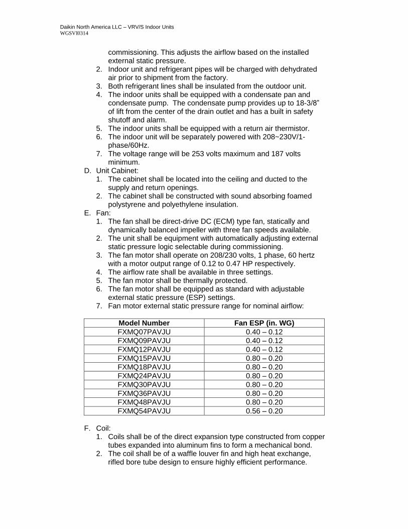
external static pressure (ESP) settings. 7. Fan motor external static pressure range for nominal airflow:
Model Number Fan ESP (in. WG)
FXMQ07PAVJU 0.40 – 0.12
FXMQ09PAVJU 0.40 – 0.12
FXMQ12PAVJU 0.40 – 0.12
FXMQ15PAVJU 0.80 – 0.20
FXMQ18PAVJU 0.80 – 0.20
FXMQ24PAVJU 0.80 – 0.20
FXMQ30PAVJU 0.80 – 0.20
FXMQ36PAVJU 0.80 – 0.20
FXMQ48PAVJU 0.80 – 0.20
FXMQ54PAVJU 0.56 – 0.20
F. Coil:
1. Coils shall be of the direct expansion type constructed from copper tubes expanded into aluminum fins to form a mechanical bond.
2. The coil shall be of a waffle louver fin and high heat exchange, rifled bore tube design to ensure highly efficient performance.
Daikin North America LLC – VRV/S Indoor Units WGSVI0314
3. The coil shall be a 3 row cross fin copper evaporator coil with 13 fpi design completely factory tested.
4. The refrigerant connections shall be flare connections and the condensate will be 1-1/4” outside diameter PVC.
5. A condensate pan shall be located under the coil. 6. A condensate pump with an 18-3/8” lift shall be located below the
coil in the condensate pan with a built in safety alarm. 7. A thermistor will be located on the liquid and gas line.
G. Electrical: 1. A separate power supply will be required of 208/230 volts, 1 phase,
60 hertz. The acceptable voltage range shall be 187 to 253 volts. 2. Transmission (control) wiring between the indoor and outdoor unit
shall be a maximum of 3,280 feet (total 6,560 feet). 3. Transmission (control) wiring between the indoor unit and remote
controller shall be a maximum distance of 1,640 feet. H. Control:
1. The unit shall have controls provided by Daikin to perform input functions necessary to operate the system.
2. The unit shall be compatible with interfacing with a BMS system via optional LonWorks or BACnet gateways.
3. The unit shall be compatible with a Daikin Intelligent Touch Manager advanced multi-zone controller.
I. Optional Accessories Available: 1. Remote “in-room” sensor kit KRCS01-4B (recommended).
1. The Daikin wall mounted, hard wired remote sensor kit is recommended for when a NAV controller is not used or when the NAV controller is not located in the space that is being controlled. The sensor for detecting the temperature can be placed away from the indoor unit (branch wiring is included in the kit).
2. MERV 13 Filter kit. Can be configured for right or left access. Filters replaceable without tools.
3. Air side Economizer designed for connection to the rear of FXMQ30-54PAVJU.
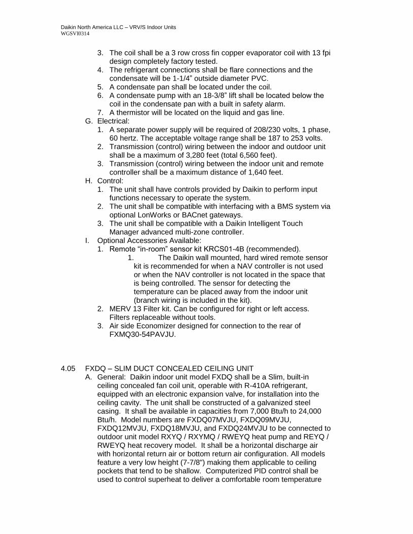
4.05 FXDQ – SLIM DUCT CONCEALED CEILING UNIT
A. General: Daikin indoor unit model FXDQ shall be a Slim, built-in ceiling concealed fan coil unit, operable with R-410A refrigerant, equipped with an electronic expansion valve, for installation into the ceiling cavity. The unit shall be constructed of a galvanized steel casing. It shall be available in capacities from 7,000 Btu/h to 24,000 Btu/h. Model numbers are FXDQ07MVJU, FXDQ09MVJU, FXDQ12MVJU, FXDQ18MVJU, and FXDQ24MVJU to be connected to outdoor unit model RXYQ / RXYMQ / RWEYQ heat pump and REYQ / RWEYQ heat recovery model. It shall be a horizontal discharge air with horizontal return air or bottom return air configuration. All models feature a very low height (7-7/8") making them applicable to ceiling pockets that tend to be shallow. Computerized PID control shall be used to control superheat to deliver a comfortable room temperature
Daikin North America LLC – VRV/S Indoor Units WGSVI0314
condition. The unit shall be equipped with a programmed drying mechanism that dehumidifies while limiting changes in room temperature when used with Daikin remote control BRC1E72 and BRC2A71. Included as standard equipment, a long-life filter that is mold resistant and a condensate drain pan and drain pump kit that pumps to 23-5/8" from the drain pipe opening. The indoor units sound pressure level shall range from 29 dB(A) to 32 dB(A) at low speed and 33 dB(A) to 36 dB(A) at high speed 5 feet below the suction grille.
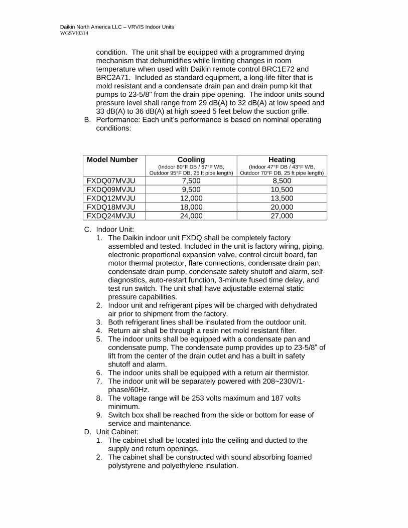
B. Performance: Each unit’s performance is based on nominal operating conditions:
C. Indoor Unit: 1. The Daikin indoor unit FXDQ shall be completely factory
assembled and tested. Included in the unit is factory wiring, piping, electronic proportional expansion valve, control circuit board, fan motor thermal protector, flare connections, condensate drain pan, condensate drain pump, condensate safety shutoff and alarm, self-diagnostics, auto-restart function, 3-minute fused time delay, and test run switch. The unit shall have adjustable external static pressure capabilities.
2. Indoor unit and refrigerant pipes will be charged with dehydrated air prior to shipment from the factory.
3. Both refrigerant lines shall be insulated from the outdoor unit. 4. Return air shall be through a resin net mold resistant filter. 5. The indoor units shall be equipped with a condensate pan and
condensate pump. The condensate pump provides up to 23-5/8” of lift from the center of the drain outlet and has a built in safety shutoff and alarm.
6. The indoor units shall be equipped with a return air thermistor. 7. The indoor unit will be separately powered with 208~230V/1-
phase/60Hz. 8. The voltage range will be 253 volts maximum and 187 volts
minimum. 9. Switch box shall be reached from the side or bottom for ease of
service and maintenance. D. Unit Cabinet:
1. The cabinet shall be located into the ceiling and ducted to the supply and return openings.
2. The cabinet shall be constructed with sound absorbing foamed polystyrene and polyethylene insulation.
Model Number Cooling (Indoor 80°F DB / 67°F WB,
Outdoor 95°F DB, 25 ft pipe length)
Heating (Indoor 47°F DB / 43°F WB,
Outdoor 70°F DB, 25 ft pipe length)
FXDQ07MVJU 7,500 8,500
FXDQ09MVJU 9,500 10,500
FXDQ12MVJU 12,000 13,500
FXDQ18MVJU 18,000 20,000
FXDQ24MVJU 24,000 27,000
Daikin North America LLC – VRV/S Indoor Units WGSVI0314
E. Fan: 1. The fan shall be direct-drive Sirocco type fan, statically and
dynamically balanced impeller with high and low fan speeds available.
2. The fan motor shall operate on 208/230 volts, 1 phase, 60 hertz with a motor output range from 62W to 130W.
3. The airflow rate shall be available in high and low settings. 4. The fan motor shall be thermally protected. 5. The fan motor shall be equipped as standard with adjustable
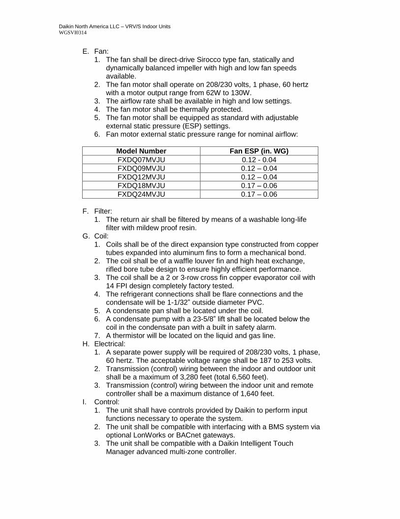
external static pressure (ESP) settings. 6. Fan motor external static pressure range for nominal airflow:
Model Number Fan ESP (in. WG)
FXDQ07MVJU 0.12 - 0.04
FXDQ09MVJU 0.12 – 0.04
FXDQ12MVJU 0.12 – 0.04
FXDQ18MVJU 0.17 – 0.06
FXDQ24MVJU 0.17 – 0.06
F. Filter:
1. The return air shall be filtered by means of a washable long-life filter with mildew proof resin.
G. Coil: 1. Coils shall be of the direct expansion type constructed from copper
tubes expanded into aluminum fins to form a mechanical bond. 2. The coil shall be of a waffle louver fin and high heat exchange,
rifled bore tube design to ensure highly efficient performance. 3. The coil shall be a 2 or 3-row cross fin copper evaporator coil with
14 FPI design completely factory tested. 4. The refrigerant connections shall be flare connections and the
condensate will be 1-1/32” outside diameter PVC. 5. A condensate pan shall be located under the coil. 6. A condensate pump with a 23-5/8” lift shall be located below the
coil in the condensate pan with a built in safety alarm. 7. A thermistor will be located on the liquid and gas line.
H. Electrical: 1. A separate power supply will be required of 208/230 volts, 1 phase,
60 hertz. The acceptable voltage range shall be 187 to 253 volts. 2. Transmission (control) wiring between the indoor and outdoor unit
shall be a maximum of 3,280 feet (total 6,560 feet). 3. Transmission (control) wiring between the indoor unit and remote
controller shall be a maximum distance of 1,640 feet. I. Control:
1. The unit shall have controls provided by Daikin to perform input functions necessary to operate the system.
2. The unit shall be compatible with interfacing with a BMS system via optional LonWorks or BACnet gateways.
3. The unit shall be compatible with a Daikin Intelligent Touch Manager advanced multi-zone controller.
Daikin North America LLC – VRV/S Indoor Units WGSVI0314
J. Optional Accessories Available: 1. Remote “in-room” sensor kit KRCS01-1B (recommended).
i. The Daikin wall mounted, hard wired remote sensor kit is recommended for ceiling-embedded type fan coils, which often result in a difference between set temperature and actual temperature. The sensor for detecting the temperature can be placed away from the indoor unit (branch wiring is included in the kit).
4.06 FXHQ – CEILING SUSPENDED CASSETTE UNIT
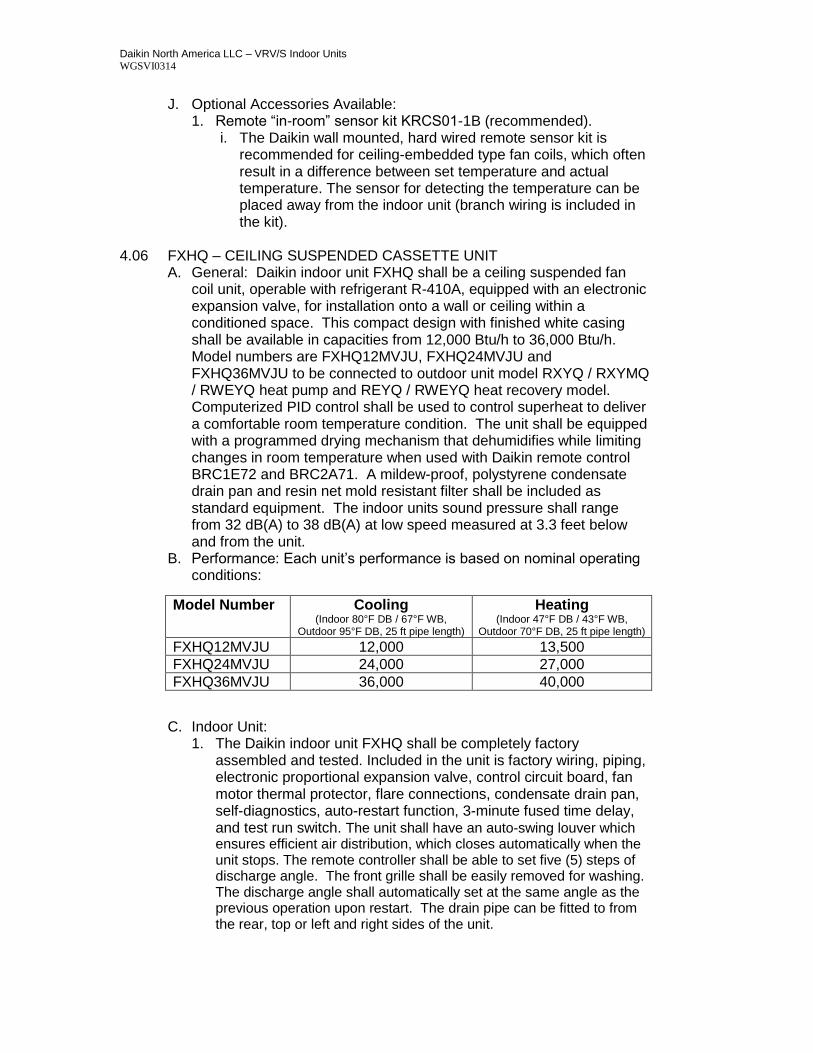
A. General: Daikin indoor unit FXHQ shall be a ceiling suspended fan coil unit, operable with refrigerant R-410A, equipped with an electronic expansion valve, for installation onto a wall or ceiling within a conditioned space. This compact design with finished white casing shall be available in capacities from 12,000 Btu/h to 36,000 Btu/h. Model numbers are FXHQ12MVJU, FXHQ24MVJU and FXHQ36MVJU to be connected to outdoor unit model RXYQ / RXYMQ / RWEYQ heat pump and REYQ / RWEYQ heat recovery model. Computerized PID control shall be used to control superheat to deliver a comfortable room temperature condition. The unit shall be equipped with a programmed drying mechanism that dehumidifies while limiting changes in room temperature when used with Daikin remote control BRC1E72 and BRC2A71. A mildew-proof, polystyrene condensate drain pan and resin net mold resistant filter shall be included as standard equipment. The indoor units sound pressure shall range from 32 dB(A) to 38 dB(A) at low speed measured at 3.3 feet below and from the unit.
B. Performance: Each unit’s performance is based on nominal operating conditions:
C. Indoor Unit:
1. The Daikin indoor unit FXHQ shall be completely factory assembled and tested. Included in the unit is factory wiring, piping, electronic proportional expansion valve, control circuit board, fan motor thermal protector, flare connections, condensate drain pan, self-diagnostics, auto-restart function, 3-minute fused time delay, and test run switch. The unit shall have an auto-swing louver which ensures efficient air distribution, which closes automatically when the unit stops. The remote controller shall be able to set five (5) steps of discharge angle. The front grille shall be easily removed for washing. The discharge angle shall automatically set at the same angle as the previous operation upon restart. The drain pipe can be fitted to from the rear, top or left and right sides of the unit.
Model Number Cooling (Indoor 80°F DB / 67°F WB,
Outdoor 95°F DB, 25 ft pipe length)
Heating (Indoor 47°F DB / 43°F WB,
Outdoor 70°F DB, 25 ft pipe length) FXHQ12MVJU 12,000 13,500
FXHQ24MVJU 24,000 27,000
FXHQ36MVJU 36,000 40,000
Daikin North America LLC – VRV/S Indoor Units WGSVI0314
2. Indoor unit and refrigerant pipes will be charged with dehydrated air prior to shipment from the factory.
3. Both refrigerant lines shall be insulated from the outdoor unit. 4. Return air shall be through a resin net mold resistant filter. 5. The indoor units shall be equipped with a condensate pan. 6. The indoor units shall be equipped with a return air thermistor. 7. The indoor unit will be separately powered with 208~230V/1-
phase/60Hz. 8. The voltage range will be 253 volts maximum and 187 volts
minimum. D. Unit Cabinet:
1. The cabinet shall be affixed to a factory supplied wall/ceiling hanging brackets and located in the conditioned space.
2. The cabinet shall be constructed with sound absorbing foamed polystyrene and polyethylene insulation.
E. Fan: 1. The fan shall be a direct-drive cross-flow fan, statically and
dynamically balanced impeller with high and low fan speeds available.
2. The fan motor shall operate on 208/230 volts, 1 phase, 60 hertz with a motor output range 62W to 130W.
3. The airflow rate shall be available in high and low settings. 4. The fan motor shall be thermally protected.
F. Coil: 1. Coils shall be of the direct expansion type constructed from copper
tubes expanded into aluminum fins to form a mechanical bond. 2. The coil shall be of a waffle louver fin and high heat exchange,
rifled bore tube design to ensure highly efficient performance. 3. The coil shall be a 2-row cross fin copper evaporator coil with 15
fpi design completely factory tested. 4. The refrigerant connections shall be flare connections and the
condensate will be 1 inch outside diameter PVC. 5. A thermistor will be located on the liquid and gas line. 6. A condensate pan shall be located in the unit.
G. Electrical: 1. A separate power supply will be required of 208/230 volts, 1 phase,
60 hertz. The acceptable voltage range shall be 187 to 253 volts. 2. Transmission (control) wiring between the indoor and outdoor unit
shall be a maximum of 3,280 feet (total 6,560 feet). 3. Transmission (control) wiring between the indoor unit and remote
controller shall be a maximum distance of 1,640 feet. H. Control:
1. The unit shall have controls provided by Daikin to perform input
functions necessary to operate the system. 2. The unit shall be compatible with interfacing with a BMS system via
optional LonWorks or BACnet gateways. 3. The unit shall be compatible with a Daikin Intelligent Touch
Manager advanced multi-zone controller.
Daikin North America LLC – VRV/S Indoor Units WGSVI0314
I. Optional Accessories Available: 1. Remote “in-room” sensor kit KRCS01-1B. 2. A condensate pump (DACA-CP3-1).
4.07 FXAQ – WALL MOUNTED UNIT
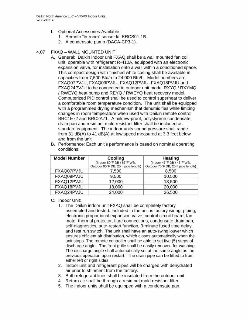
A. General: Daikin indoor unit FXAQ shall be a wall mounted fan coil unit, operable with refrigerant R-410A, equipped with an electronic expansion valve, for installation onto a wall within a conditioned space. This compact design with finished white casing shall be available in capacities from 7,500 Btu/h to 24,000 Btu/h. Model numbers are FXAQ07PVJU, FXAQ09PVJU, FXAQ12PVJU, FXAQ18PVJU and FXAQ24PVJU to be connected to outdoor unit model RXYQ / RXYMQ / RWEYQ heat pump and REYQ / RWEYQ heat recovery model. Computerized PID control shall be used to control superheat to deliver a comfortable room temperature condition. The unit shall be equipped with a programmed drying mechanism that dehumidifies while limiting changes in room temperature when used with Daikin remote control BRC1E72 and BRC2A71. A mildew-proof, polystyrene condensate drain pan and resin net mold resistant filter shall be included as standard equipment. The indoor units sound pressure shall range from 31 dB(A) to 41 dB(A) at low speed measured at 3.3 feet below and from the unit.
B. Performance: Each unit’s performance is based on nominal operating conditions:
C. Indoor Unit: 1. The Daikin indoor unit FXAQ shall be completely factory
assembled and tested. Included in the unit is factory wiring, piping, electronic proportional expansion valve, control circuit board, fan motor thermal protector, flare connections, condensate drain pan, self-diagnostics, auto-restart function, 3-minute fused time delay, and test run switch. The unit shall have an auto-swing louver which ensures efficient air distribution, which closes automatically when the unit stops. The remote controller shall be able to set five (5) steps of discharge angle. The front grille shall be easily removed for washing. The discharge angle shall automatically set at the same angle as the previous operation upon restart. The drain pipe can be fitted to from either left or right sides.
2. Indoor unit and refrigerant pipes will be charged with dehydrated air prior to shipment from the factory.
3. Both refrigerant lines shall be insulated from the outdoor unit. 4. Return air shall be through a resin net mold resistant filter. 5. The indoor units shall be equipped with a condensate pan.
Model Number Cooling (Indoor 80°F DB / 67°F WB,
Outdoor 95°F DB, 25 ft pipe length)
Heating (Indoor 47°F DB / 43°F WB,
Outdoor 70°F DB, 25 ft pipe length) FXAQ07PVJU 7,500 8,500
FXAQ09PVJU 9,500 10,500
FXAQ12PVJU 12,000 13,500
FXAQ18PVJU 18,000 20,000
FXAQ24PVJU 24,000 26,500
Daikin North America LLC – VRV/S Indoor Units WGSVI0314
6. The indoor units shall be equipped with a return air thermistor. 7. The indoor unit will be separately powered with 208~230V/1-
phase/60Hz. 8. The voltage range will be 253 volts maximum and 187 volts
minimum. D. Unit Cabinet:
1. The cabinet shall be affixed to a factory supplied wall mounting template and located in the conditioned space.
2. The cabinet shall be constructed with sound absorbing foamed polystyrene and polyethylene insulation.
E. Fan: 1. The fan shall be a direct-drive cross-flow fan, statically and
dynamically balanced impeller with high and low fan speeds available.
2. The fan motor shall operate on 208/230 volts, 1 phase, 60 hertz with a motor output range 0.054 to 0.058 HP.
3. The airflow rate shall be available in high and low settings. 4. The fan motor shall be thermally protected.
F. Coil: 1. Coils shall be of the direct expansion type constructed from copper
tubes expanded into aluminum fins to form a mechanical bond. 2. The coil shall be of a waffle louver fin and high heat exchange,
rifled bore tube design to ensure highly efficient performance. 3. The coil shall be a 2-row cross fin copper evaporator coil with 14
fpi design completely factory tested. 4. The refrigerant connections shall be flare connections and the
condensate will be 11/16 inch outside diameter PVC. 5. A thermistor will be located on the liquid and gas line. 6. A condensate pan shall be located in the unit.
G. Electrical: 1. A separate power supply will be required of 208/230 volts, 1 phase,
60 hertz. The acceptable voltage range shall be 187 to 253 volts. 2. Transmission (control) wiring between the indoor and outdoor unit
shall be a maximum of 3,280 feet (total 6,560 feet). 3. Transmission (control) wiring between the indoor unit and remote
controller shall be a maximum distance of 1,640 feet. H. Control:
1. The unit shall have controls provided by Daikin to perform input functions necessary to operate the system.
2. The unit shall be compatible with interfacing with a BMS system via optional LonWorks or BACnet gateways.
3. The unit shall be compatible with a Daikin Intelligent Touch Manager advanced multi-zone controller.
I. Optional Accessories Available: 1. Remote “in-room” sensor kit KRCS01-1B. 2. A condensate pump (DACA-CP3-1).
Daikin North America LLC – VRV/S Indoor Units WGSVI0314
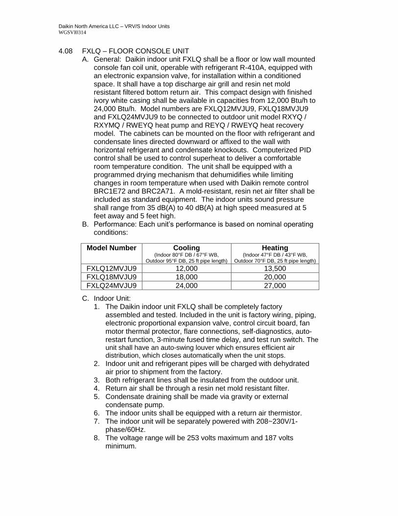
4.08 FXLQ – FLOOR CONSOLE UNIT A. General: Daikin indoor unit FXLQ shall be a floor or low wall mounted
console fan coil unit, operable with refrigerant R-410A, equipped with an electronic expansion valve, for installation within a conditioned space. It shall have a top discharge air grill and resin net mold resistant filtered bottom return air. This compact design with finished ivory white casing shall be available in capacities from 12,000 Btu/h to 24,000 Btu/h. Model numbers are FXLQ12MVJU9, FXLQ18MVJU9 and FXLQ24MVJU9 to be connected to outdoor unit model RXYQ / RXYMQ / RWEYQ heat pump and REYQ / RWEYQ heat recovery model. The cabinets can be mounted on the floor with refrigerant and condensate lines directed downward or affixed to the wall with horizontal refrigerant and condensate knockouts. Computerized PID control shall be used to control superheat to deliver a comfortable room temperature condition. The unit shall be equipped with a programmed drying mechanism that dehumidifies while limiting changes in room temperature when used with Daikin remote control BRC1E72 and BRC2A71. A mold-resistant, resin net air filter shall be included as standard equipment. The indoor units sound pressure shall range from 35 dB(A) to 40 dB(A) at high speed measured at 5 feet away and 5 feet high.
B. Performance: Each unit’s performance is based on nominal operating conditions:
C. Indoor Unit: 1. The Daikin indoor unit FXLQ shall be completely factory
assembled and tested. Included in the unit is factory wiring, piping, electronic proportional expansion valve, control circuit board, fan motor thermal protector, flare connections, self-diagnostics, auto-restart function, 3-minute fused time delay, and test run switch. The unit shall have an auto-swing louver which ensures efficient air distribution, which closes automatically when the unit stops.
2. Indoor unit and refrigerant pipes will be charged with dehydrated air prior to shipment from the factory.
3. Both refrigerant lines shall be insulated from the outdoor unit. 4. Return air shall be through a resin net mold resistant filter. 5. Condensate draining shall be made via gravity or external
condensate pump. 6. The indoor units shall be equipped with a return air thermistor. 7. The indoor unit will be separately powered with 208~230V/1-
phase/60Hz. 8. The voltage range will be 253 volts maximum and 187 volts
minimum.
Model Number Cooling (Indoor 80°F DB / 67°F WB,
Outdoor 95°F DB, 25 ft pipe length)
Heating (Indoor 47°F DB / 43°F WB,
Outdoor 70°F DB, 25 ft pipe length) FXLQ12MVJU9 12,000 13,500
FXLQ18MVJU9 18,000 20,000
FXLQ24MVJU9 24,000 27,000
Daikin North America LLC – VRV/S Indoor Units WGSVI0314
D. Unit Cabinet: 1. The cabinet shall be affixed to a factory supplied wall mounting
template and located in the conditioned space. 2. The cabinet shall be constructed with sound absorbing fiberglass
urethane foam insulation. 3. Maintenance access shall be a minimum of ¾ inch in the rear, 4
inches on the right and left sides. E. Fan:
1. The fan shall be a direct-drive Sirocco type fan, statically and dynamically balanced impeller with high and low fan speeds available.
2. The fan motor shall operate on 208/230 volts, 1 phase, 60 hertz with a motor output range 0.034 to 0.047 HP.
3. The airflow rate shall be available in high and low settings. 4. The fan motor shall be thermally protected.
F. Filter: 1. The return air shall be filtered by means of a washable long-life
filter with mildew proof resin. G. Coil:
1. Coils shall be of the direct expansion type constructed from copper tubes expanded into aluminum fins to form a mechanical bond.
2. The coil shall be of a waffle louver fin and high heat exchange, rifled bore tube design to ensure highly efficient performance.
3. The coil shall be a 3-row cross fin copper evaporator coil with 17 fpi design completely factory tested.
4. The refrigerant connections shall be flare connections and the condensate will be 27/32 inch outside diameter PVC.
5. A thermistor will be located on the liquid and gas line. H. Electrical:
1. A separate power supply will be required of 208/230 volts, 1 phase, 60 hertz. The acceptable voltage range shall be 187 to 253 volts.
2. Transmission (control) wiring between the indoor and outdoor unit shall be a maximum of 3,280 feet (total 6,560 feet).
3. Transmission (control) wiring between the indoor unit and remote controller shall be a maximum distance of 1,640 feet.
I. Control: 1. The unit shall have controls provided by Daikin to perform input
functions necessary to operate the system. 2. The unit shall be compatible with interfacing with a BMS system via
optional LonWorks or BACnet gateways. 3. The unit shall be compatible with a Daikin Intelligent Touch
Manager advanced multi-zone controller. J. Optional Accessories Available:
1. Remote “in-room” sensor kit KRCS01-1B.
Daikin North America LLC – VRV/S Indoor Units WGSVI0314
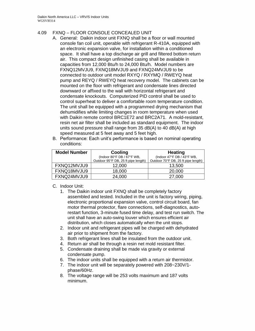
4.09 FXNQ – FLOOR CONSOLE CONCEALED UNIT A. General: Daikin indoor unit FXNQ shall be a floor or wall mounted
console fan coil unit, operable with refrigerant R-410A, equipped with an electronic expansion valve, for installation within a conditioned space. It shall have a top discharge air grill and filtered bottom return air. This compact design unfinished casing shall be available in capacities from 12,000 Btu/h to 24,000 Btu/h. Model numbers are FXNQ12MVJU9, FXNQ18MVJU9 and FXNQ24MVJU9 to be connected to outdoor unit model RXYQ / RXYMQ / RWEYQ heat pump and REYQ / RWEYQ heat recovery model. The cabinets can be mounted on the floor with refrigerant and condensate lines directed downward or affixed to the wall with horizontal refrigerant and condensate knockouts. Computerized PID control shall be used to control superheat to deliver a comfortable room temperature condition. The unit shall be equipped with a programmed drying mechanism that dehumidifies while limiting changes in room temperature when used with Daikin remote control BRC1E72 and BRC2A71. A mold-resistant, resin net air filter shall be included as standard equipment. The indoor units sound pressure shall range from 35 dB(A) to 40 dB(A) at high speed measured at 5 feet away and 5 feet high.
B. Performance: Each unit’s performance is based on nominal operating conditions:
C. Indoor Unit:
1. The Daikin indoor unit FXNQ shall be completely factory assembled and tested. Included in the unit is factory wiring, piping, electronic proportional expansion valve, control circuit board, fan motor thermal protector, flare connections, self-diagnostics, auto-restart function, 3-minute fused time delay, and test run switch. The unit shall have an auto-swing louver which ensures efficient air distribution, which closes automatically when the unit stops.
2. Indoor unit and refrigerant pipes will be charged with dehydrated air prior to shipment from the factory.
3. Both refrigerant lines shall be insulated from the outdoor unit. 4. Return air shall be through a resin net mold resistant filter. 5. Condensate draining shall be made via gravity or external
condensate pump. 6. The indoor units shall be equipped with a return air thermistor. 7. The indoor unit will be separately powered with 208~230V/1-
phase/60Hz. 8. The voltage range will be 253 volts maximum and 187 volts
minimum.
Model Number Cooling (Indoor 80°F DB / 67°F WB,
Outdoor 95°F DB, 25 ft pipe length)
Heating (Indoor 47°F DB / 43°F WB,
Outdoor 70°F DB, 25 ft pipe length) FXNQ12MVJU9 12,000 13,500
FXNQ18MVJU9 18,000 20,000
FXNQ24MVJU9 24,000 27,000
Daikin North America LLC – VRV/S Indoor Units WGSVI0314
D. Unit Cabinet: 1. The cabinet shall be affixed to a factory supplied wall mounting
template and located in the conditioned space. 2. The cabinet shall be constructed with sound absorbing fiberglass
urethane foam insulation. 3. Maintenance access shall be a minimum of ¾ inch in the rear, 4
inches on the right and left sides. E. Fan:
1. The fan shall be a direct-drive Sirocco type fan, statically and dynamically balanced impeller with high and low fan speeds available.
2. The fan motor shall operate on 208/230 volts, 1 phase, 60 hertz with a motor output range 0.034 to 0.047 HP.
3. The airflow rate shall be available in high and low settings. 4. The fan motor shall be thermally protected.
F. Filter: 1. The return air shall be filtered by means of a washable long-life
filter with mildew proof resin. G. Coil:
1. Coils shall be of the direct expansion type constructed from copper tubes expanded into aluminum fins to form a mechanical bond.
2. The coil shall be of a waffle louver fin and high heat exchange, rifled bore tube design to ensure highly efficient performance.
3. The coil shall be a 3-row cross fin copper evaporator coil with 17 fpi design completely factory tested.
4. The refrigerant connections shall be flare connections and the condensate will be 27/32 inch outside diameter PVC.
5. A thermistor will be located on the liquid and gas line. H. Electrical:
1. A separate power supply will be required of 208/230 volts, 1 phase, 60 hertz. The acceptable voltage range shall be 187 to 253 volts.
2. Transmission (control) wiring between the indoor and outdoor unit shall be a maximum of 3,280 feet (total 6,560 feet).
3. Transmission (control) wiring between the indoor unit and remote controller shall be a maximum distance of 1,640 feet.
I. Control: 1. The unit shall have controls provided by Daikin to perform input
functions necessary to operate the system. 2. The unit shall be compatible with interfacing with a BMS system via
optional LonWorks or BACnet gateways. 3. The unit shall be compatible with a Daikin Intelligent Touch
Manager advanced multi-zone controller. J. Optional Accessories Available:
1. Remote “in-room” sensor kit KRCS01-1B. 2. A condensate pump (DACA-CP3-1).
Daikin North America LLC – VRV/S Indoor Units WGSVI0314
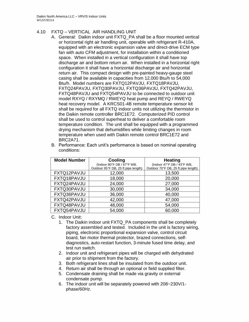
4.10 FXTQ – VERTICAL AIR HANDLING UNIT A. General: Daikin indoor unit FXTQ_PA shall be a floor mounted vertical
or horizontal right air handling unit, operable with refrigerant R-410A, equipped with an electronic expansion valve and direct-drive ECM type fan with auto CFM adjustment, for installation within a conditioned space. When installed in a vertical configuration it shall have top discharge air and bottom return air. When installed in a horizontal right configuration it shall have a horizontal discharge air and horizontal return air. This compact design with pre-painted heavy-gauge steel casing shall be available in capacities from 12,000 Btu/h to 54,000 Btu/h. Model numbers are FXTQ12PAVJU, FXTQ18PAVJU, FXTQ24PAVJU, FXTQ30PAVJU, FXTQ36PAVJU, FXTQ42PAVJU, FXTQ48PAVJU and FXTQ54PAVJU to be connected to outdoor unit model RXYQ / RXYMQ / RWEYQ heat pump and REYQ / RWEYQ heat recovery model. A KRCS01-4B remote temperature sensor kit shall be required for all FXTQ indoor units not utilizing the thermistor in the Daikin remote controller BRC1E72. Computerized PID control shall be used to control superheat to deliver a comfortable room temperature condition. The unit shall be equipped with a programmed drying mechanism that dehumidifies while limiting changes in room temperature when used with Daikin remote control BRC1E72 and BRC2A71.
B. Performance: Each unit’s performance is based on nominal operating conditions:
C. Indoor Unit: 1. The Daikin indoor unit FXTQ_PA components shall be completely
factory assembled and tested. Included in the unit is factory wiring, piping, electronic proportional expansion valve, control circuit board, fan motor thermal protector, brazed connections, self-diagnostics, auto-restart function, 3-minute fused time delay, and test run switch.
2. Indoor unit and refrigerant pipes will be charged with dehydrated air prior to shipment from the factory.
3. Both refrigerant lines shall be insulated from the outdoor unit. 4. Return air shall be through an optional or field supplied filter. 5. Condensate draining shall be made via gravity or external
condensate pump. 6. The indoor unit will be separately powered with 208~230V/1-
phase/60Hz.
Model Number Cooling (Indoor 80°F DB / 67°F WB,
Outdoor 95°F DB, 25 ft pipe length)
Heating (Indoor 47°F DB / 43°F WB,
Outdoor 70°F DB, 25 ft pipe length) FXTQ12PAVJU 12,000 13,500
FXTQ18PAVJU 18,000 20,000
FXTQ24PAVJU 24,000 27,000
FXTQ30PAVJU 30,000 34,000
FXTQ36PAVJU 36,000 40,000
FXTQ42PAVJU 42,000 47,000
FXTQ48PAVJU 48,000 54,000
FXTQ54PAVJU 54,000 60,000
Daikin North America LLC – VRV/S Indoor Units WGSVI0314
7. The voltage range will be 253 volts maximum and 187 volts minimum.
D. Unit Cabinet: 1. The cabinet shall be constructed with sound absorbing, foil-faced
insulation to control air leakage. 2. Select an installation location with adequate structural support,
space for service access and clearance for air return and supply duct connections.
3. A field supplied secondary drain pan must be installed E. Fan:
1. The fan shall be a direct-drive Sirocco type fan, statically and dynamically balanced impeller with high and low fan speeds available.
2. The fan motor shall operate on 208/230 volts, 1 phase, 60 hertz with a motor output range 0.2 to 0.5 HP.
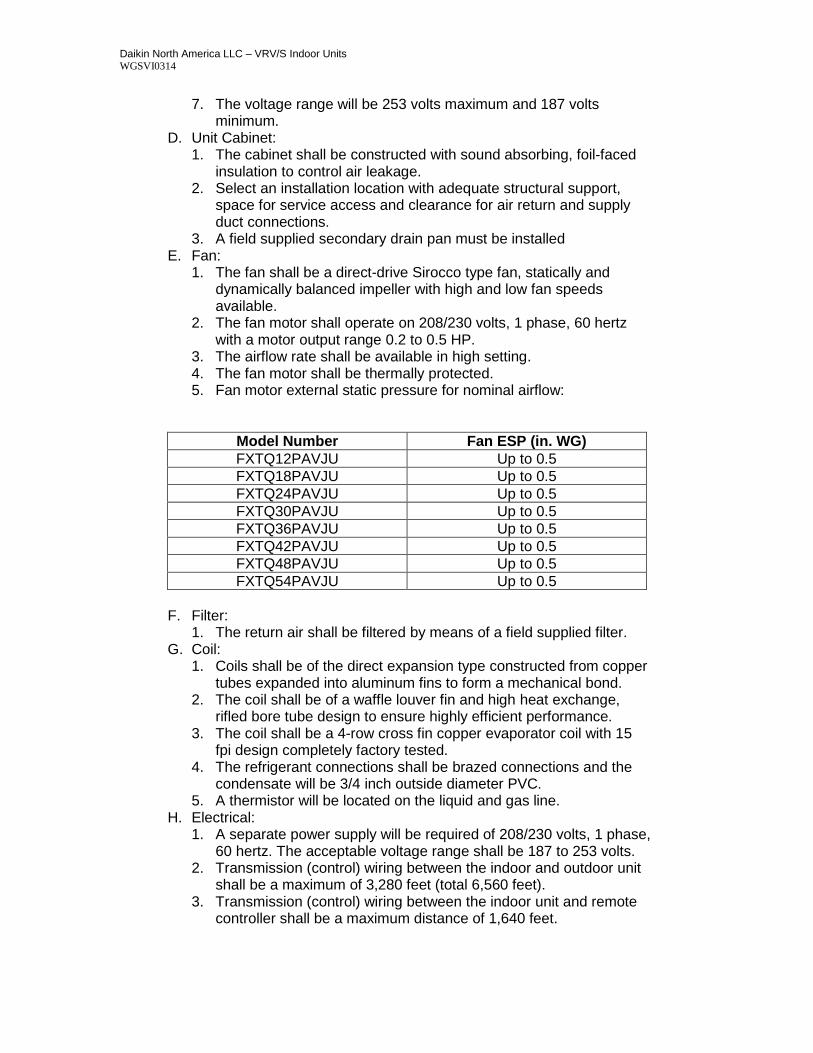
3. The airflow rate shall be available in high setting. 4. The fan motor shall be thermally protected. 5. Fan motor external static pressure for nominal airflow:
Model Number Fan ESP (in. WG)
FXTQ12PAVJU Up to 0.5
FXTQ18PAVJU Up to 0.5
FXTQ24PAVJU Up to 0.5
FXTQ30PAVJU Up to 0.5
FXTQ36PAVJU Up to 0.5
FXTQ42PAVJU Up to 0.5
FXTQ48PAVJU Up to 0.5
FXTQ54PAVJU Up to 0.5
F. Filter:
1. The return air shall be filtered by means of a field supplied filter. G. Coil:
1. Coils shall be of the direct expansion type constructed from copper tubes expanded into aluminum fins to form a mechanical bond.
2. The coil shall be of a waffle louver fin and high heat exchange, rifled bore tube design to ensure highly efficient performance.
3. The coil shall be a 4-row cross fin copper evaporator coil with 15 fpi design completely factory tested.
4. The refrigerant connections shall be brazed connections and the condensate will be 3/4 inch outside diameter PVC.
5. A thermistor will be located on the liquid and gas line. H. Electrical:
1. A separate power supply will be required of 208/230 volts, 1 phase, 60 hertz. The acceptable voltage range shall be 187 to 253 volts.
2. Transmission (control) wiring between the indoor and outdoor unit shall be a maximum of 3,280 feet (total 6,560 feet).
3. Transmission (control) wiring between the indoor unit and remote controller shall be a maximum distance of 1,640 feet.
Daikin North America LLC – VRV/S Indoor Units WGSVI0314
I. Control: 1. The unit shall have controls provided by Daikin to perform input
functions necessary to operate the system. 2. The unit shall be compatible with interfacing with a BMS system via
optional LonWorks or BACnet gateways. 3. The unit shall be compatible with a Daikin Intelligent Touch
Manager advanced multi-zone controller. J. Optional Accessories Available:
1. Field installed 3-20kW electric heaters (HKR-03, HKR-05C, HKR-06, HKR-08C, HKR-10C). The indoor units shall have circuit breakers supplied with each electric heat kit.
2. Air filter (FIL 36-42, FIL 48-61). 3. Insulation kit for vertical (DPI 36-42/20, DPI 48-61/20) and
horizontal (DPIH 36-42, DPIH 48-61) configurations. 4. BRC4C84 wireless controller.
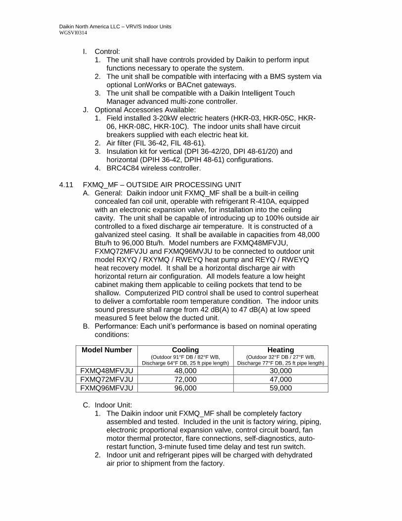
4.11 FXMQ_MF – OUTSIDE AIR PROCESSING UNIT
A. General: Daikin indoor unit FXMQ_MF shall be a built-in ceiling concealed fan coil unit, operable with refrigerant R-410A, equipped with an electronic expansion valve, for installation into the ceiling cavity. The unit shall be capable of introducing up to 100% outside air controlled to a fixed discharge air temperature. It is constructed of a galvanized steel casing. It shall be available in capacities from 48,000 Btu/h to 96,000 Btu/h. Model numbers are FXMQ48MFVJU, FXMQ72MFVJU and FXMQ96MVJU to be connected to outdoor unit model RXYQ / RXYMQ / RWEYQ heat pump and REYQ / RWEYQ heat recovery model. It shall be a horizontal discharge air with horizontal return air configuration. All models feature a low height cabinet making them applicable to ceiling pockets that tend to be shallow. Computerized PID control shall be used to control superheat to deliver a comfortable room temperature condition. The indoor units sound pressure shall range from 42 dB(A) to 47 dB(A) at low speed measured 5 feet below the ducted unit.
B. Performance: Each unit’s performance is based on nominal operating conditions:
C. Indoor Unit:
1. The Daikin indoor unit FXMQ_MF shall be completely factory assembled and tested. Included in the unit is factory wiring, piping, electronic proportional expansion valve, control circuit board, fan motor thermal protector, flare connections, self-diagnostics, auto-restart function, 3-minute fused time delay and test run switch.
2. Indoor unit and refrigerant pipes will be charged with dehydrated air prior to shipment from the factory.
Model Number Cooling (Outdoor 91°F DB / 82°F WB,
Discharge 64°F DB, 25 ft pipe length)
Heating (Outdoor 32°F DB / 27°F WB,
Discharge 77°F DB, 25 ft pipe length) FXMQ48MFVJU 48,000 30,000
FXMQ72MFVJU 72,000 47,000
FXMQ96MFVJU 96,000 59,000
Daikin North America LLC – VRV/S Indoor Units WGSVI0314
3. Both refrigerant lines shall be insulated from the outdoor unit. 4. The indoor units shall be equipped with a discharge air thermistor. 5. The indoor unit will be separately powered with 208~230V/1-
phase/60Hz. 6. The voltage range will be 253 volts maximum and 187 volts
minimum. D. Unit Cabinet:
1. The cabinet shall be located into the ceiling and ducted to the supply and return openings.
2. The cabinet shall be constructed with sound absorbing foamed polystyrene and polyethylene insulation.
E. Fan: 1. The fan shall be direct-drive Sirocco type fan, statically and
dynamically balanced impeller with high and low fan speeds available.
2. The fan motor shall operate on 208/230 volts, 1 phase, 60 hertz, with a motor output of 0.51 HP.
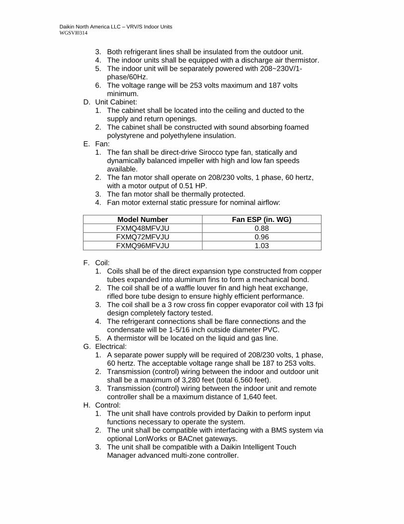
3. The fan motor shall be thermally protected. 4. Fan motor external static pressure for nominal airflow:
Model Number Fan ESP (in. WG)
FXMQ48MFVJU 0.88
FXMQ72MFVJU 0.96
FXMQ96MFVJU 1.03
F. Coil:
1. Coils shall be of the direct expansion type constructed from copper tubes expanded into aluminum fins to form a mechanical bond.
2. The coil shall be of a waffle louver fin and high heat exchange, rifled bore tube design to ensure highly efficient performance.
3. The coil shall be a 3 row cross fin copper evaporator coil with 13 fpi design completely factory tested.
4. The refrigerant connections shall be flare connections and the condensate will be 1-5/16 inch outside diameter PVC.
5. A thermistor will be located on the liquid and gas line. G. Electrical:
1. A separate power supply will be required of 208/230 volts, 1 phase, 60 hertz. The acceptable voltage range shall be 187 to 253 volts.
2. Transmission (control) wiring between the indoor and outdoor unit shall be a maximum of 3,280 feet (total 6,560 feet).
3. Transmission (control) wiring between the indoor unit and remote controller shall be a maximum distance of 1,640 feet.
H. Control: 1. The unit shall have controls provided by Daikin to perform input
functions necessary to operate the system. 2. The unit shall be compatible with interfacing with a BMS system via
optional LonWorks or BACnet gateways. 3. The unit shall be compatible with a Daikin Intelligent Touch
Manager advanced multi-zone controller.
Daikin North America LLC – VRV/S Indoor Units WGSVI0314
Part 5 - HVAC EQUIPMENT ALTERNATE (GENERAL INFORMATION) 5.01 The alternate equipment supplier shall provide to the bidding mechanical
contractor a complete equipment data package. This package shall include, but is not limited to, equipment capacities at the design condition, power requirements, indoor units CFM/static pressures, fan curves, installation requirements, and physical dimensions. Nominal performance data is not acceptable.
The mechanical contractor shall request and receive the equipment data package 15 days prior to bid date and submit this package with the alternate bid.
The mechanical contractor shall list the equipment supplier and submit the required data package with the bid detailing a complete comparison of the proposed alternate equipment to the specified equipment and the associated cost reduction of the alternate equipment. The contractor bids an alternate manufacturer with full knowledge that that manufactures product may not be acceptable or approved.
5.02 The alternate equipment supplier shall furnish a complete drawing package to the
mechanical contractor 15 days prior to bid day for bidding and installation. The drawing format shall be .dxf or equivalent, on 30"x42" sheets. The HVAC and electrical series design documents will be made available in electronic format for use by the equipment supplier in preparing their drawings. The alternate equipment supplier shall prepare the following drawings:
XXX HVAC Floor Plan XXX HVAC Refrigerant Piping Plan XXX HVAC Refrigerant Piping/Controls Details XXX HVAC Details XXX HVAC Schedules
The alternate equipment supplier shall draft all piping circuits, components, overall building control schematic, detailed control wiring diagrams, system details and schedules for their system. The drawings shall convey all requirements to successfully install the alternate equipment suppliers system.
Provide (2) drawing package sets plotted on 20 lb. vellum. Provide (1) drawing package in electronic format (.dxf files) on CD.
The submitted documents shall be complete system designs and show no less information than the HVAC equipment/controls contract bid documents.
5.03 The equipment supplier shall submit as part of the equipment data package
outdoor unit data sheets. Data sheets to include the following:
Capacities at project design conditions: Cooling Cooling (Btu/h)
Cooling Input Power (kW)
Daikin North America LLC – VRV/S Indoor Units WGSVI0314
Capacities at project design conditions: Heating Heating (Btu/h)
Heating Input Power (kW) The submitted capacity and efficiency performance must meet or exceed the listed performance on the schedule at the designed outdoor ambient, and indoor space temperature conditions including de-rate factors for defrost and refrigerant piping lengths. Operating Temperature Range: Cooling Heating
Power Supply: Maximum Circuit Amps (MCA) Maximum Overcurrent Protection Amps (MOP) Maximum Starting Current (MSC) Outdoor Fan Motor
Refrigerant: Refrigerant Type/Charge
Control
Unit Data: Max. Number of Indoor Units Sound Pressure Level at 3ft. (dBA) Weight (lbs) Dimensions
5.04 The equipment supplier shall guarantee the performance of their system and all
published data submitted. Performance shall be based on the design criteria below.
Room Temperature (Cooling): _________________________________ Room Temperature (Heating): _________________________________ Ambient Temperature (Summer): _______________________________
Ambient Temperature (Winter): ________________________________ Defrost De-rate Factor: _______________________________________ Refrigerant Piping Loss in cooling (correction factor): _______________
Refrigerant Piping Loss in heating (correction factor): _______________ 5.05 The alternate equipment supplier shall submit with bid, indoor unit data sheets.
Data sheets to include the following:
Capacities: Cooling (Btu/h) Heating (Btu/h) Air Flow (CFM)
Daikin North America LLC – VRV/S Indoor Units WGSVI0314
External Static Pressure (ESP) Electrical Data (MCA, MOP, MSC) Weight (lbs) Dimensions