D4NL Guard Lock Safety-Door Switch Datasheet · 1 CSM_D4NL_DS_E_8_1 Guard Lock Safety-door Switch...
20
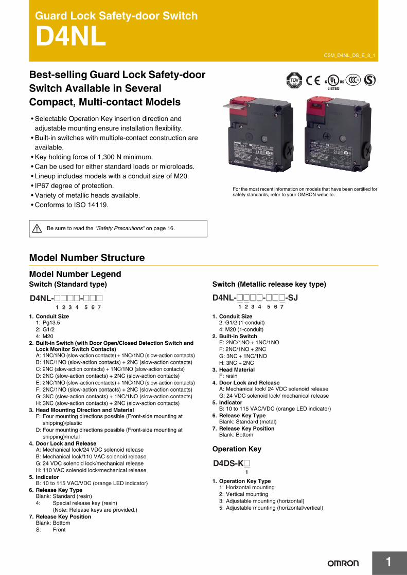
1 CSM_D4NL_DS_E_8_1 Guard Lock Safety-door Switch D4NL Best-selling Guard Lock Safety-door Switch Available in Several Compact, Multi-contact Models • Selectable Operation Key insertion direction and adjustable mounting ensure installation flexibility. • Built-in switches with multiple-contact construction are available. • Key holding force of 1,300 N minimum. • Can be used for either standard loads or microloads. • Lineup includes models with a conduit size of M20. • IP67 degree of protection. • Variety of metallic heads available. • Conforms to ISO 14119. Model Number Structure Model Number Legend Switch (Standard type) 1. Conduit Size 1: Pg13.5 2: G1/2 4: M20 2. Built-in Switch (with Door Open/Closed Detection Switch and Lock Monitor Switch Contacts) A: 1NC/1NO (slow-action contacts) + 1NC/1NO (slow-action contacts) B: 1NC/1NO (slow-action contacts) + 2NC (slow-action contacts) C: 2NC (slow-action contacts) + 1NC/1NO (slow-action contacts) D: 2NC (slow-action contacts) + 2NC (slow-action contacts) E: 2NC/1NO (slow-action contacts) + 1NC/1NO (slow-action contacts) F: 2NC/1NO (slow-action contacts) + 2NC (slow-action contacts) G: 3NC (slow-action contacts) + 1NC/1NO (slow-action contacts) H: 3NC (slow-action contacts) + 2NC (slow-action contacts) 3. Head Mounting Direction and Material F: Four mounting directions possible (Front-side mounting at shipping)/plastic D: Four mounting directions possible (Front-side mounting at shipping)/metal 4. Door Lock and Release A: Mechanical lock/24 VDC solenoid release B: Mechanical lock/110 VAC solenoid release G: 24 VDC solenoid lock/mechanical release H: 110 VAC solenoid lock/mechanical release 5. Indicator B: 10 to 115 VAC/VDC (orange LED indicator) 6. Release Key Type Blank: Standard (resin) 4: Special release key (resin) (Note: Release keys are provided.) 7. Release Key Position Blank: Bottom S: Front Switch (Metallic release key type) 1. Conduit Size 2: G1/2 (1-conduit) 4: M20 (1-conduit) 2. Built-in Switch E: 2NC/1NO + 1NC/1NO F: 2NC/1NO + 2NC G: 3NC + 1NC/1NO H: 3NC + 2NC 3. Head Material F: resin 4. Door Lock and Release A: Mechanical lock/ 24 VDC solenoid release G: 24 VDC solenoid lock/ mechanical release 5. Indicator B: 10 to 115 VAC/VDC (orange LED indicator) 6. Release Key Type Blank: Standard (metal) 7. Release Key Position Blank: Bottom Operation Key 1. Operation Key Type 1: Horizontal mounting 2: Vertical mounting 3: Adjustable mounting (horizontal) 5: Adjustable mounting (horizontal/vertical) Be sure to read the “Safety Precautions” on page 16. For the most recent information on models that have been certified for safety standards, refer to your OMRON website. 1234 567 D4NL-@@@@-@@@ 1 2 3 4 5 6 7 D4NL-@@@@-@@@-SJ 1 D4DS-K@
Transcript of D4NL Guard Lock Safety-Door Switch Datasheet · 1 CSM_D4NL_DS_E_8_1 Guard Lock Safety-door Switch...
1
CSM_D4NL_DS_E_8_1
Guard Lock Safety-door Switch
D4NLBest-selling Guard Lock Safety-door Switch Available in Several Compact, Multi-contact Models
• Selectable Operation Key insertion direction andadjustable mounting ensure installation flexibility.
• Built-in switches with multiple-contact construction areavailable.
• Key holding force of 1,300 N minimum.• Can be used for either standard loads or microloads.• Lineup includes models with a conduit size of M20.• IP67 degree of protection.• Variety of metallic heads available.• Conforms to ISO 14119.
Model Number Structure
Model Number LegendSwitch (Standard type)
1. Conduit Size1: Pg13.52: G1/24: M20
2. Built-in Switch (with Door Open/Closed Detection Switch and Lock Monitor Switch Contacts)A: 1NC/1NO (slow-action contacts) + 1NC/1NO (slow-action contacts)B: 1NC/1NO (slow-action contacts) + 2NC (slow-action contacts)C: 2NC (slow-action contacts) + 1NC/1NO (slow-action contacts)D: 2NC (slow-action contacts) + 2NC (slow-action contacts)E: 2NC/1NO (slow-action contacts) + 1NC/1NO (slow-action contacts)F: 2NC/1NO (slow-action contacts) + 2NC (slow-action contacts)G: 3NC (slow-action contacts) + 1NC/1NO (slow-action contacts)H: 3NC (slow-action contacts) + 2NC (slow-action contacts)
3. Head Mounting Direction and MaterialF: Four mounting directions possible (Front-side mounting at
shipping)/plasticD: Four mounting directions possible (Front-side mounting at
shipping)/metal4. Door Lock and Release
A: Mechanical lock/24 VDC solenoid releaseB: Mechanical lock/110 VAC solenoid releaseG: 24 VDC solenoid lock/mechanical releaseH: 110 VAC solenoid lock/mechanical release
5. IndicatorB: 10 to 115 VAC/VDC (orange LED indicator)
6. Release Key TypeBlank: Standard (resin)4: Special release key (resin)
(Note: Release keys are provided.)7. Release Key Position
Blank: BottomS: Front
Switch (Metallic release key type)
1. Conduit Size2: G1/2 (1-conduit)4: M20 (1-conduit)
2. Built-in SwitchE: 2NC/1NO + 1NC/1NOF: 2NC/1NO + 2NCG: 3NC + 1NC/1NOH: 3NC + 2NC
3. Head MaterialF: resin
4. Door Lock and ReleaseA: Mechanical lock/ 24 VDC solenoid releaseG: 24 VDC solenoid lock/ mechanical release
5. IndicatorB: 10 to 115 VAC/VDC (orange LED indicator)
6. Release Key TypeBlank: Standard (metal)
7. Release Key PositionBlank: Bottom
Operation Key
1. Operation Key Type1: Horizontal mounting2: Vertical mounting3: Adjustable mounting (horizontal)5: Adjustable mounting (horizontal/vertical)
Be sure to read the “Safety Precautions” on page 16.
For the most recent information on models that have been certified for safety standards, refer to your OMRON website.
1 2 3 4 5 6 7
D4NL-@@@@-@@@1 2 3 4 5 6 7
D4NL-@@@@-@@@-SJ
1D4DS-K@
D4NL
2
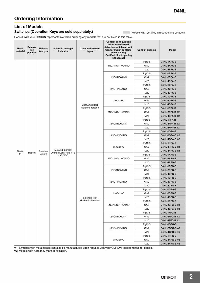
Ordering Information
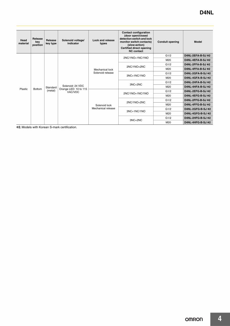
List of ModelsSwitches (Operation Keys are sold separately.)Consult with your OMRON representative when ordering any models that are not listed in this table.
*1. Switches with metal heads can also be manufactured upon request. Ask your OMRON representative for details.*2. Models with Korean S-mark certification.
Head material
Release key
position
Release key type
Solenoid voltage/indicator
Lock and release types
Contact configuration (door open/closed
detection switch and lock monitor switch contacts)
(slow-action)Certified direct opening
NC contact
Conduit opening Model
Plastic *1 Bottom Standard
(resin)
Solenoid: 24 VDCOrange LED: 10 to 115
VAC/VDC
Mechanical lockSolenoid release
1NC/1NO+1NC/1NO
Pg13.5 D4NL-1AFA-B
G1/2 D4NL-2AFA-B
M20 D4NL-4AFA-B
1NC/1NO+2NC
Pg13.5 D4NL-1BFA-B
G1/2 D4NL-2BFA-B
M20 D4NL-4BFA-B
2NC+1NC/1NO
Pg13.5 D4NL-1CFA-B
G1/2 D4NL-2CFA-B
M20 D4NL-4CFA-B
2NC+2NC
Pg13.5 D4NL-1DFA-B
G1/2 D4NL-2DFA-B
M20 D4NL-4DFA-B
2NC/1NO+1NC/1NO
Pg13.5 D4NL-1EFA-B
G1/2 D4NL-2EFA-B *2
M20 D4NL-4EFA-B *2
2NC/1NO+2NC
Pg13.5 D4NL-1FFA-B
G1/2 D4NL-2FFA-B *2
M20 D4NL-4FFA-B *2
3NC+1NC/1NO
Pg13.5 D4NL-1GFA-B
G1/2 D4NL-2GFA-B *2
M20 D4NL-4GFA-B *2
3NC+2NC
Pg13.5 D4NL-1HFA-B
G1/2 D4NL-2HFA-B *2
M20 D4NL-4HFA-B *2
Solenoid lockMechanical release
1NC/1NO+1NC/1NO
Pg13.5 D4NL-1AFG-B
G1/2 D4NL-2AFG-B
M20 D4NL-4AFG-B
1NC/1NO+2NC
Pg13.5 D4NL-1BFG-B
G1/2 D4NL-2BFG-B
M20 D4NL-4BFG-B
2NC+1NC/1NO
Pg13.5 D4NL-1CFG-B
G1/2 D4NL-2CFG-B
M20 D4NL-4CFG-B
2NC+2NC
Pg13.5 D4NL-1DFG-B
G1/2 D4NL-2DFG-B
M20 D4NL-4DFG-B
2NC/1NO+1NC/1NO
Pg13.5 D4NL-1EFG-B
G1/2 D4NL-2EFG-B *2
M20 D4NL-4EFG-B *2
2NC/1NO+2NC
Pg13.5 D4NL-1FFG-B
G1/2 D4NL-2FFG-B *2
M20 D4NL-4FFG-B *2
3NC+1NC/1NO
Pg13.5 D4NL-1GFG-B
G1/2 D4NL-2GFG-B *2
M20 D4NL-4GFG-B *2
3NC+2NC
Pg13.5 D4NL-1HFG-B
G1/2 D4NL-2HFG-B *2
M20 D4NL-4HFG-B *2
: Models with certified direct opening contacts.
D4NL
3
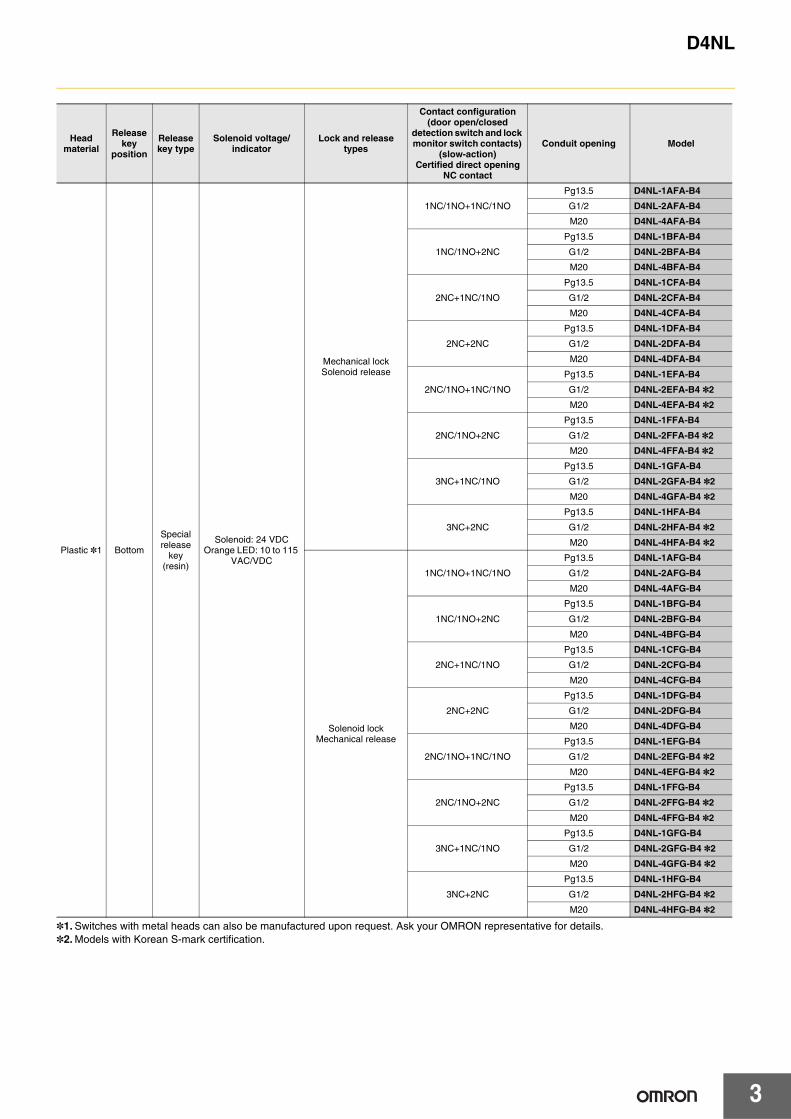
*1. Switches with metal heads can also be manufactured upon request. Ask your OMRON representative for details. *2. Models with Korean S-mark certification.
Head material
Release key
position
Release key type
Solenoid voltage/indicator
Lock and release types
Contact configuration (door open/closed
detection switch and lock monitor switch contacts)
(slow-action)Certified direct opening
NC contact
Conduit opening Model
Plastic *1 Bottom
Special release
key(resin)
Solenoid: 24 VDCOrange LED: 10 to 115
VAC/VDC
Mechanical lockSolenoid release
1NC/1NO+1NC/1NO
Pg13.5 D4NL-1AFA-B4
G1/2 D4NL-2AFA-B4
M20 D4NL-4AFA-B4
1NC/1NO+2NC
Pg13.5 D4NL-1BFA-B4
G1/2 D4NL-2BFA-B4
M20 D4NL-4BFA-B4
2NC+1NC/1NO
Pg13.5 D4NL-1CFA-B4
G1/2 D4NL-2CFA-B4
M20 D4NL-4CFA-B4
2NC+2NC
Pg13.5 D4NL-1DFA-B4
G1/2 D4NL-2DFA-B4
M20 D4NL-4DFA-B4
2NC/1NO+1NC/1NO
Pg13.5 D4NL-1EFA-B4
G1/2 D4NL-2EFA-B4 *2
M20 D4NL-4EFA-B4 *2
2NC/1NO+2NC
Pg13.5 D4NL-1FFA-B4
G1/2 D4NL-2FFA-B4 *2
M20 D4NL-4FFA-B4 *2
3NC+1NC/1NO
Pg13.5 D4NL-1GFA-B4
G1/2 D4NL-2GFA-B4 *2
M20 D4NL-4GFA-B4 *2
3NC+2NC
Pg13.5 D4NL-1HFA-B4
G1/2 D4NL-2HFA-B4 *2
M20 D4NL-4HFA-B4 *2
Solenoid lockMechanical release
1NC/1NO+1NC/1NO
Pg13.5 D4NL-1AFG-B4
G1/2 D4NL-2AFG-B4
M20 D4NL-4AFG-B4
1NC/1NO+2NC
Pg13.5 D4NL-1BFG-B4
G1/2 D4NL-2BFG-B4
M20 D4NL-4BFG-B4
2NC+1NC/1NO
Pg13.5 D4NL-1CFG-B4
G1/2 D4NL-2CFG-B4
M20 D4NL-4CFG-B4
2NC+2NC
Pg13.5 D4NL-1DFG-B4
G1/2 D4NL-2DFG-B4
M20 D4NL-4DFG-B4
2NC/1NO+1NC/1NO
Pg13.5 D4NL-1EFG-B4
G1/2 D4NL-2EFG-B4 *2
M20 D4NL-4EFG-B4 *2
2NC/1NO+2NC
Pg13.5 D4NL-1FFG-B4
G1/2 D4NL-2FFG-B4 *2
M20 D4NL-4FFG-B4 *2
3NC+1NC/1NO
Pg13.5 D4NL-1GFG-B4
G1/2 D4NL-2GFG-B4 *2
M20 D4NL-4GFG-B4 *2
3NC+2NC
Pg13.5 D4NL-1HFG-B4
G1/2 D4NL-2HFG-B4 *2
M20 D4NL-4HFG-B4 *2
D4NL
4
*2. Models with Korean S-mark certification.
Head material
Release key
position
Release key type
Solenoid voltage/indicator
Lock and release types
Contact configuration (door open/closed
detection switch and lock monitor switch contacts)
(slow-action)Certified direct opening
NC contact
Conduit opening Model
Plastic BottomStandard(metal)
Solenoid: 24 VDCOrange LED: 10 to 115
VAC/VDC
Mechanical lockSolenoid release
2NC/1NO+1NC/1NO G1/2 D4NL-2EFA-B-SJ *2
M20 D4NL-4EFA-B-SJ *2
2NC/1NO+2NC G1/2 D4NL-2FFA-B-SJ *2
M20 D4NL-4FFA-B-SJ *2
3NC+1NC/1NO G1/2 D4NL-2GFA-B-SJ *2
M20 D4NL-4GFA-B-SJ *2
3NC+2NC G1/2 D4NL-2HFA-B-SJ *2
M20 D4NL-4HFA-B-SJ *2
Solenoid lockMechanical release
2NC/1NO+1NC/1NO G1/2 D4NL-2EFG-B-SJ *2
M20 D4NL-4EFG-B-SJ *2
2NC/1NO+2NC G1/2 D4NL-2FFG-B-SJ *2
M20 D4NL-4FFG-B-SJ *2
3NC+1NC/1NO G1/2 D4NL-2GFG-B-SJ *2
M20 D4NL-4GFG-B-SJ *2
3NC+2NC G1/2 D4NL-2HFG-B-SJ *2
M20 D4NL-4HFG-B-SJ *2
D4NL
5
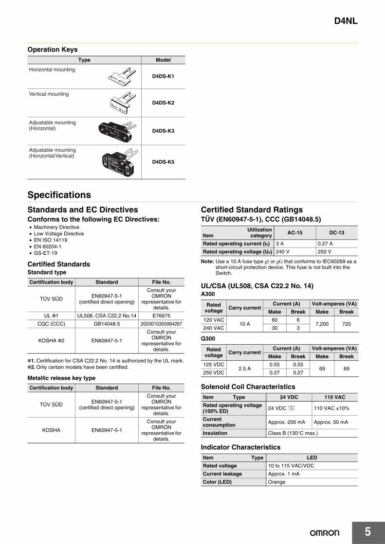
Operation Keys
Specifications
Standards and EC DirectivesConforms to the following EC Directives:• Machinery Directive• Low Voltage Directive• EN ISO 14119• EN 60204-1• GS-ET-19
Certified StandardsStandard type
*1. Certification for CSA C22.2 No. 14 is authorized by the UL mark.*2. Only certain models have been certified.
Metallic release key type
Certified Standard RatingsTÜV (EN60947-5-1), CCC (GB14048.5)
Note: Use a 10 A fuse type gI or gG that conforms to IEC60269 as a short-circuit protection device. This fuse is not built into the Switch.
UL/CSA (UL508, CSA C22.2 No. 14)A300
Q300
Solenoid Coil Characteristics
Indicator Characteristics
Type Model
D4DS-K1
D4DS-K2
D4DS-K3
D4DS-K5
Horizontal mounting
Vertical mounting
Adjustable mounting(Horizontal)
Adjustable mounting(Horizontal/Vertical)
Certification body Standard File No.
TÜV SÜD EN60947-5-1 (certified direct opening)
Consult your OMRON
representative for details.
UL *1 UL508, CSA C22.2 No.14 E76675
CQC (CCC) GB14048.5 2003010305064267
KOSHA *2 EN60947-5-1
Consult your OMRON
representative for details.
Certification body Standard File No.
TÜV SÜD EN60947-5-1 (certified direct opening)
Consult your OMRON
representative for details.
KOSHA EN60947-5-1
Consult your OMRON
representative for details.
ItemUtilization
category AC-15 DC-13
Rated operating current (Ie) 3 A 0.27 A
Rated operating voltage (Ue) 240 V 250 V
Rated voltage Carry current
Current (A) Volt-amperes (VA)
Make Break Make Break
120 VAC10 A
60 67,200 720
240 VAC 30 3
Rated voltage Carry current
Current (A) Volt-amperes (VA)
Make Break Make Break
125 VDC2.5 A
0.55 0.5569 69
250 VDC 0.27 0.27
Item Type 24 VDC 110 VAC
Rated operating voltage (100% ED) 24 VDC 110 VAC ±10%
Current consumption Approx. 200 mA Approx. 50 mA
Insulation Class B (130°C max.)
Item Type LED
Rated voltage 10 to 115 VAC/VDC
Current leakage Approx. 1 mA
Color (LED) Orange
+10%−15%

D4NL
6
Characteristics
Note: 1. The above values are initial values.2. The Switch contacts can be used with either standard loads or microloads. Once the contacts have been used to switch a load, however,
they cannot be used to switch smaller loads. The contact surfaces will become rough once they have been used and contact reliability for smaller loads may be reduced.
*1. The degree of protection is tested using the method specified by the standard (EN60947-5-1). Confirm that sealing properties are sufficient for the operating conditions and environment beforehand. Although the switch box is protected from dust or water penetration, do not use the D4NL in places where foreign material may enter through the key hole on the head, otherwise Switch damage or malfunctioning may occur.
*2. The durability is for an ambient temperature of 5 to 35°C and an ambient humidity of 40% to 70%. For more details, consult your OMRON representative.
*3. Do not pass the 3 A, 250 VAC load through more than 2 circuits.*4. These figures are minimum requirements for safe operation.*5. This figure is based on the GS-ET-19 evaluation method.*6. This value will vary with the switching frequency, environment, and reliability level. Confirm that correct operation is possible with the actual
load beforehand.
Degree of protection *1 IP67 (EN60947-5-1)
Durability *2Mechanical 1,000,000 operations min.
Electrical 500,000 operations min. (3 A resistive load at 250 VAC) *3
Operating speed 0.05 to 0.5 m/s
Operating frequency 30 operations/minute max.
Direct opening force *4 60 N min. (EN60947-5-1)
Direct opening travel *4 10 mm min. (EN60947-5-1)
Holding force *5 1,300 N min.
Contact resistance 25 mΩ max. (per contact)
Minimum applicable load *6 1 mA resistive load at 5 VDC (N-level reference value)
Rated insulation voltage (Ui) 300 V (EN60947-5-1)
Rated frequency 50/60 Hz
Protection against electric shock Class II (double insulation)
Pollution degree (operating environment) 3 (EN60947-5-1)
Impulse withstand voltage (EN60947-5-1)
Between terminals of same polarity 2.5 kV
Between terminals of different polarity 4 kV
Between each terminal and non-current carrying metallic parts
6 kV
Insulation resistance 100 MΩ min. (at 500 VDC)
Contact gap 2 × 2 mm min.
Vibration resistance Malfunction 10 to 55 Hz, 0.75 mm single amplitude
Shock resistanceDestruction 1,000 m/s2 min.
Malfunction 100 m/s2 min.
Conditional short-circuit current 100 A (EN60947-5-1)
Conventional free air thermal current (Ith) 10 A (EN60947-5-1)
Ambient operating temperature −10 to 55°C (with no icing)
Ambient operating humidity 95% max.
Weight Approx. 370 g (D4NL-1AFA-B)

D4NL
7
Connections
Internal Circuit DiagramIndicator
Solenoid
Circuit Connection ExampleConnection Example for D4NL-@F@@-B• Terminals 12 and 41 are connected internally. When connecting
inputs to safety circuits, use terminals 11 and 42. (GS-ET-19).• Connect terminals 21 and 22 and terminals 51 and 52 in series
when using as safety-circuit inputs (redundancy circuit for terminals 11 and 12 and terminals 41 and 42 below). Connect the terminals individually when using as auxiliary-circuit inputs (e.g., terminals 21 and 22 for safety-door open/closed monitoring and terminals 51 and 52 for monitoring the lock status).
• In the following connection example, terminals 21 and 22 and terminals 51 and 52 are used as auxiliary-circuit inputs.
• Direct opening contacts used as safety-circuit inputs are indicated with the mark. Terminals 11 and 42, and terminals 21 and 22 have direct opening contacts.
• Connect the indicators in parallel to the auxiliary circuits or terminals E1 and E2 (D4NL-@@@A-B, -@@@G-B, -@@@B-B, and -@@@H-B only). Connecting to contacts with direct opening mechanisms may result in short-circuit current flowing if the indicator is destroyed, possibly resulting in incorrect equipment operation.
• Do not switch circuits for two or more standard loads at the same time. Doing so may adversely affect insulation performance.
• DC solenoids have polarity. Confirm terminal polarity before wiring.
D
R
RLEDZ
10 to 115 VAC/VDC
Constant-current diode
E1 (+)
E2 (−)
24 VDC
E1 (+)
E2 (−)
110 VAC/230 VAC
42 11
21
33
E1 (+)
O1 O2
12 41
51
52
22
34
E2 (−)
Indicator (Orange)
Safety circuit
Auxiliary circuit
Auxiliary circuit
Auxiliary circuit
D4NL
8
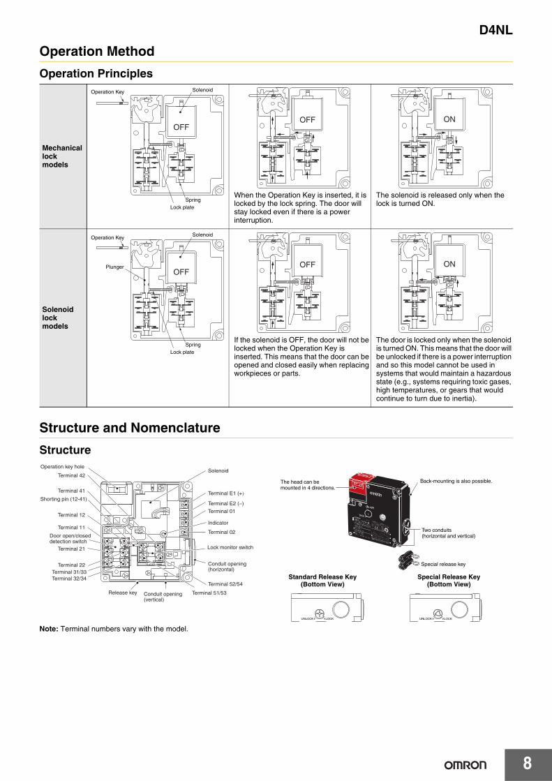
Operation Method
Operation Principles
Structure and Nomenclature
Structure
Note: Terminal numbers vary with the model.
Mechanical lock models
When the Operation Key is inserted, it is locked by the lock spring. The door will stay locked even if there is a power interruption.
The solenoid is released only when the lock is turned ON.
Solenoid lock models
If the solenoid is OFF, the door will not be locked when the Operation Key is inserted. This means that the door can be opened and closed easily when replacing workpieces or parts.
The door is locked only when the solenoid is turned ON. This means that the door will be unlocked if there is a power interruption and so this model cannot be used in systems that would maintain a hazardous state (e.g., systems requiring toxic gases, high temperatures, or gears that would continue to turn due to inertia).
SolenoidOperation Key
Lock plateSpring
OFFOFF ON
SolenoidOperation Key
Lock plateSpring
OFFPlunger OFF ON
Special release key
The head can bemounted in 4 directions.
Two conduits(horizontal and vertical)
Back-mounting is also possible.
Operation key hole
Terminal 42
Terminal 41
Shorting pin (12-41)
Terminal 12
Terminal 11
Door open/closeddetection switch
Terminal 21
Terminal 22Terminal 31/33Terminal 32/34
Release key Conduit opening (vertical)
Terminal 51/53
Terminal 52/54
Conduit opening (horizontal)
Lock monitor switch
Terminal 02
Indicator
Terminal 01
Terminal E1 (+)
Terminal E2 (−)
Solenoid
UNLOCK LOCK UNLOCK LOCK
Standard Release Key (Bottom View)
Special Release Key (Bottom View)

D4NL
9
Contact FormIndicates conditions where the Key is inserted and the lock is applied. Terminals 12 and 41 are connected internally (as per GS-ET-19).
Model
Contact(door open/closed detection and lock
monitor)
Contact form
Operating pattern RemarksDoor open/closed
detection
Lock monitor
D4NL-@AF@-@ 1NC/1NO + 1NC/1NO
D4NL-@BF@-@ 1NC/1NO + 2NC
D4NL-@CF@-@ 2NC + 1NC/1NO
D4NL-@DF@-@ 2NC + 2NC
D4NL-@EF@-@ 2NC/1NO + 1NC/1NO
D4NL-@FF@-@ 2NC/1NO + 2NC
D4NL-@GF@-@ 3NC + 1NC/1NO
D4NL-@HF@-@ 3NC + 2NC
11Zb Zb
33 34
12 41 42
5453
Door open/closed detection
Lock monitor11-4233-3453-54
ON
Extraction completionposition
Operation Key insertioncompletion position
Stroke
Lock positionOnly NC contacts 11-12 have a certified direct opening mechanism.
The terminals 11-42, 33-34, and 53-54 can be used as unlike poles.
11
33 34
12 41 42
5251
Zb Zb
Door open/closed detection
Lock monitor11-4233-3451-52
ON
Extraction completionposition
Operation Key insertioncompletion position
Stroke
Lock positionOnly NC contacts 11-12 have a certified direct opening mechanism.
The terminals 11-42, 33-34, and 51-52 can be used as unlike poles.
11
31 32
12 41 42
5453
Zb Zb
Door open/closed detection
Lock monitor11-4231-3253-54
ON
Extraction completionposition
Operation Key insertioncompletion position
Stroke
Lock position Only NC contacts 11-12 and 31-32 have a certified direct opening mechanism.
The terminals 11-42, 31-32, and 53-54 can be used as unlike poles.
11
31 32
12 41 42
5251
Zb Zb
Door open/closed detection
Lock monitor11-4231-3251-52
11-42
51-52ON
Extraction completionposition
Operation Key insertioncompletion position
Stroke
Lock position Only NC contacts 11-12 and 31-32 have a certified direct opening mechanism.
The terminals 11-42, 31-32, and 51-52 can be used as unlike poles.
11
21 22
33 34
12 41 42
5453
Zb Zb
Door open/closed detection
Lock monitor11-4221-2233-3453-54
11-4221-2233-3453-54
ON
Extraction completionposition
Operation Key insertioncompletion position
Stroke
Lock position Only NC contacts 11-12 and 21-22 have a certified direct opening mechanism.
The terminals 11-42, 21-22, 33-34, and 53-54 can be used as unlike poles.
11
21 22
33 34
12 41 42
5251
Zb Zb
Door open/closed detection
Lock monitor 11-4221-2233-3451-52
ON
Extraction completion position
Operation Key insertioncompletion position
Stroke
Lock positionOnly NC contacts 11-12 and 21-22 have a certified direct opening mechanism.
The terminals 11-42, 21-22, 33-34, and 51-52 can be used as unlike poles.
11
21 22
31 32
12 41 42
5453
Zb Zb
Door open/closed detection
Lock monitor 11-4221-2231-3253-54
ON
Extraction completionposition
Operation Key insertioncompletion position
Stroke
Lock position Only NC contacts 11-12, 21-22, and 31-32 have a certified direct opening mechanism.
The terminals 11-42, 21-22, 31-32, and 53-54 can be used as unlike poles.
11
21 22
31 32
12 41 42
5251
Zb Zb
Door open/closed detection
Lock monitor11-4221-2231-3251-52
ON
Extraction completionposition
Operation Key insertioncompletion position
Stroke
Lock position Only NC contacts 11-12, 21-22, and 31-32 have a certified direct opening mechanism.The terminals 11-42, 21-22, 31-32, and 51-52 can be used as unlike poles.

D4NL
10
Dimensions (Unit: mm)
Dimensions and Operating CharacteristicsSwitchesD4NL-@@@@-B
D4NL-@@@@-B4
Note: 1. Unless otherwise specified, a tolerance of ±0.4 mm applies to all dimensions.2. There are fluctuations in the contact ON/OFF timing for Switches with multiple poles (2NC, 2NC/1NO, or 3NC). Confirm performance
before application.
RedBlack
UNLOCK
LOCK
UNLOCK LOCK
30.515.5 8
15.3
10.0
4.428.5
59
(30.7)
(57.9)
79±0.2
(88.5)
5 4.5
(55.8)
(13.3)
55±0.2
(95)(32.3)
(3)
4
4
6.5
6.5
29
29
(15.3)
(10)
35.5
0.5
0.5
6.5
29
32±0.2
Four, head mounting screws
Pre-travel distance
Five, covermounting screws
Dummy capIndicator
Three, 4.3-dia. holes
Cap screw
Conduit cap
Conduit opening
Release key
Operation Key
Operating characteristics
Model D4NL-@@@@-B
Key insertion forceKey extraction force
15 N max.30 N max.
Pre-travel distance 9 mm max.
Movement before being locked 3 mm min.
RedBlack
UNLOCK
LOCK
UNLOCK LOCK
30.515.5 8
15.3
10.0
4.428.5
59
(30.7)
(57.9)
79±0.2
(88.5)
5 4.5
(55.8)
(13.3)
55±0.2
(95)(32.3)
(3)
4
4
6.5
6.5
29
29
(10)
35.5
0.5
0.5
6.5
29
32±0.2
8
21
10.5
(15.3)
Four, head mounting screwsPre-travel distance
Five, covermounting screws
Dummy capIndicator
Three, 4.3-dia. holes
Cap screw
Conduit cap
Conduit opening
Release key
Operation Key
Releasing tool(provided)M8 hexagonal material
or equivalent
Operating characteristics
Model D4NL-@@@@-B4
Key insertion forceKey extraction force
15 N max.30 N max.
Pre-travel distance 9 mm max.
Movement before being locked 3 mm min.

D4NL
11
D4NL-@@@@-BS
D4NL-@@@@-B4S
Note: 1. Unless otherwise specified, a tolerance of ±0.4 mm applies to all dimensions.2. There are fluctuations in the contact ON/OFF timing for Switches with multiple poles (2NC, 2NC/1NO, or 3NC). Confirm performance
before application.
Operation Keys
Note: Unless otherwise specified, a tolerance of ±0.4 mm applies to all dimensions.
RedBlack
UNLOCK LOCK
UNLOCK
LOCK
30.515.5 8
15.3
10.0
4.428.5
59
(30.7)
(57.9)
79±0.2
(88.5)
5 4.5
(55.8)(31.5)
(13.3)
55±0.2
(95)(32.3)
(3)
4
4
6.5
6.5
29
29
35.5
0.5
0.5
6.5
29
32±0.2
(15.3)
Four, head mounting screwsPre-travel distance
Five, covermounting screws
Release keyIndicator
Three, 4.3-dia. holes
Cap screw
Conduit cap
Conduit opening
Dummy cap
Operation Key
Operating characteristics
Model D4NL-@@@@-BS
Key insertion forceKey extraction force
15 N max.30 N max.
Pre-travel distance 9 mm max.
Movement before being locked 3 mm min.
RedBlack
UNLOCK
LOCK
UNLOCK LOCK
30.515.5 8
15.3
10.0
4.428.5
59
(30.7)
(57.9)
79±0.2
(88.5)
5 4.5
(55.8)
(13.3)
55±0.2
(95)(32.3)
(3)
4
4
6.5
6.5
29
29
35.5
0.5
0.5
6.5
29
32±0.2
8
21
10.5
(15.3)
(31.5)
Four, head mounting screwsPre-travel distance
Indicator
Three, 4.3-dia. holes
Cap screw
Conduit cap
Operation Key
Releasing tool(provided)M8 hexagonal material
or equivalent
Dummycap
Conduit opening
Release key
Five, covermounting screws
Operating characteristics
Model D4NL-@@@@-B4S
Key insertion forceKey extraction force
15 N max.30 N max.
Pre-travel distance 9 mm max.
Movement before being locked 3 mm min.
30 15
7
17.5 28
4.3
13
2
13
7
D4DS-K1
Four, 2.15R
2814
4
6.32
15
4030 5620°
13
9 dia.
4.5 dia.
8 dia.Angle adjustment bolt
Black
D4DS-K3
3
30 13 15
2 4.7
28
10.5
6 79
D4DS-K2
Four, 2.15R
D4DS-K5
Black
4
20.9 28 24 .6
22. 5
43 41 55 30
8 1 (7) 6. 5
13
15 °
18 ° 43
4.5
41
Mounting Holes (Enlargement)
8
1713.5
D4NL
12
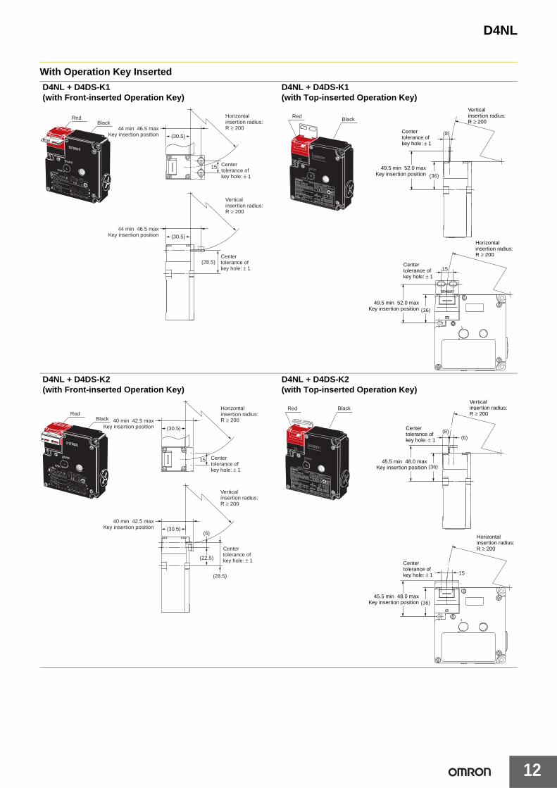
With Operation Key Inserted
D4NL + D4DS-K1(with Front-inserted Operation Key)
D4NL + D4DS-K1(with Top-inserted Operation Key)
D4NL + D4DS-K2(with Front-inserted Operation Key)
D4NL + D4DS-K2(with Top-inserted Operation Key)
Red Black
(30.5)
(30.5)
(28.5)
Center tolerance of key hole: ± 1
44 min 46.5 max Key insertion position
44 min 46.5 max Key insertion position
Horizontal insertion radius: R ≥ 200
Vertical insertion radius: R ≥ 200
15
Center tolerance of key hole: ± 1
Red Black
Horizontalinsertion radius:R ≥ 200
49.5 min 52.0 maxKey insertion position
49.5 min 52.0 maxKey insertion position
(8)
(36)
(36)
15
Centertolerance ofkey hole: ± 1
Centertolerance ofkey hole: ± 1
Verticalinsertion radius:R ≥ 200
Red Black
(30.5)
40 min 42.5 max Key insertion position
(30.5)
40 min 42.5 max Key insertion position
Center tolerance of key hole: ± 1
15
Horizontal insertion radius: R ≥ 200
Vertical insertion radius: R ≥ 200
(6)
(22.5)
(28.5)
Center tolerance of key hole: ± 1
Red Black
(8)(6)
(36)
15
Centertolerance ofkey hole: ± 1
Centertolerance ofkey hole: ± 1
45.5 min 48.0 maxKey insertion position
45.5 min 48.0 maxKey insertion position
Horizontalinsertion radius:R ≥ 200
Verticalinsertion radius:R ≥ 200
(36)
D4NL
13
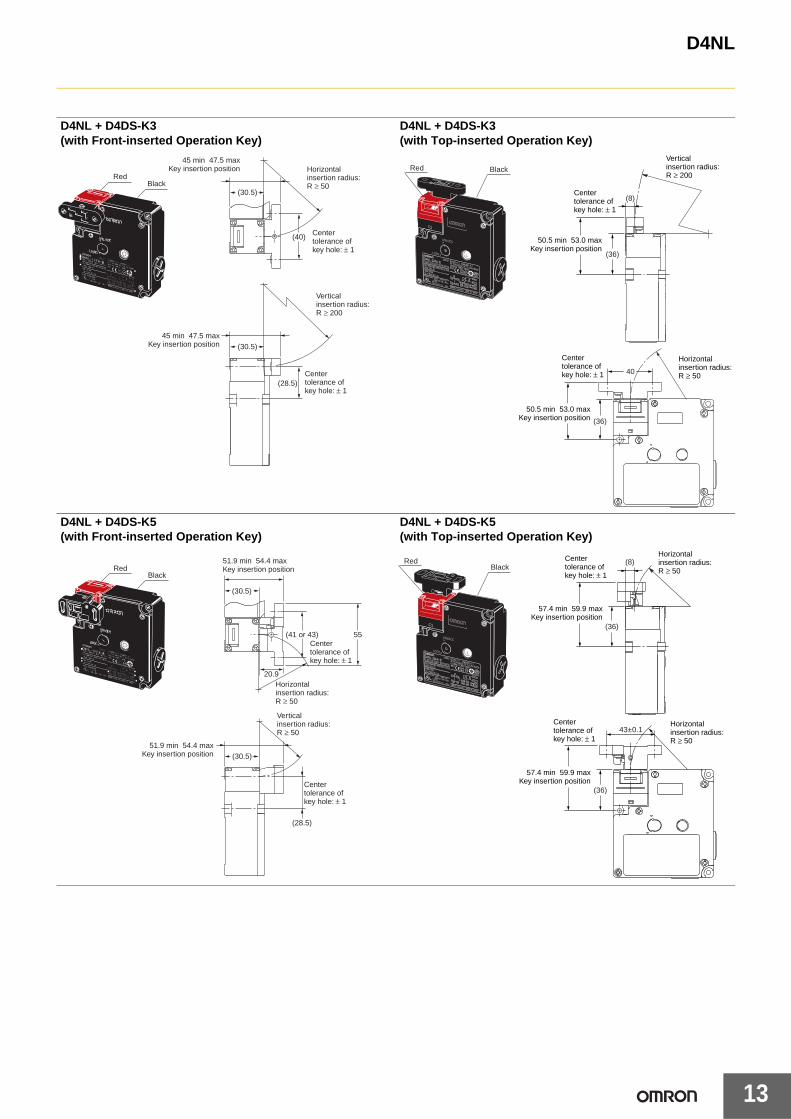
D4NL + D4DS-K3(with Front-inserted Operation Key)
D4NL + D4DS-K3(with Top-inserted Operation Key)
D4NL + D4DS-K5(with Front-inserted Operation Key)
D4NL + D4DS-K5(with Top-inserted Operation Key)
RedBlack
(30.5)
45 min 47.5 max Key insertion position
(30.5)
45 min 47.5 max Key insertion position
Horizontal insertion radius: R ≥ 50
Vertical insertion radius: R ≥ 200
Center tolerance of key hole: ± 1
(40)
Center tolerance of key hole: ± 1
(28.5)
Red Black
(8)
(36)
(36)
40
50.5 min 53.0 maxKey insertion position
50.5 min 53.0 maxKey insertion position
Horizontalinsertion radius:R ≥ 50
Verticalinsertion radius:R ≥ 200
Centertolerance ofkey hole: ± 1
Centertolerance ofkey hole: ± 1
RedBlack
(30.5)
20.9
55(41 or 43)
51.9 min 54.4 max Key insertion position
Center tolerance of key hole: ± 1
Horizontal insertion radius: R ≥ 50
Vertical insertion radius: R ≥ 50
(30.5) 51.9 min 54.4 max
Key insertion position
Center tolerance of key hole: ± 1
(28.5)
Red Black
(8)
(36)
(36)
43±0.1Horizontalinsertion radius:R ≥ 50
Horizontalinsertion radius:R ≥ 50
57.4 min 59.9 maxKey insertion position
57.4 min 59.9 maxKey insertion position
Centertolerance ofkey hole: ± 1
Centertolerance ofkey hole: ± 1
D4NL
14
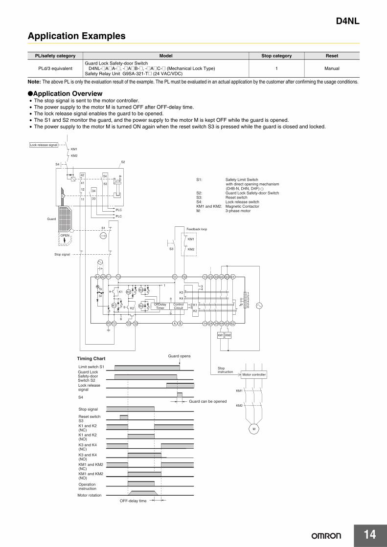
Application Examples
Note: The above PL is only the evaluation result of the example. The PL must be evaluated in an actual application by the customer after confirming the usage conditions.
●Application Overview• The stop signal is sent to the motor controller.• The power supply to the motor M is turned OFF after OFF-delay time.• The lock release signal enables the guard to be opened.• The S1 and S2 monitor the guard, and the power supply to the motor M is kept OFF while the guard is opened.• The power supply to the motor M is turned ON again when the reset switch S3 is pressed while the guard is closed and locked.
PL/safety category Model Stop category Reset
PLd/3 equivalentGuard Lock Safety-door Switch
D4NL-@A@A-@, -@A@B-@, -@A@C-@ (Mechanical Lock Type)Safety Relay Unit G9SA-321-T@ (24 VAC/VDC)
1 Manual
TH
SA
S2
OPEN
S4
KM1
KM2
42
41
12
11
PLC
PLC
54
53
34
33
A1 A2 T11 T12 T31 T32 13 23 33 43 53 61
1 2 3 4 5 6
JP
K3
3 4
2 5
K4
K1
K2
K1
K1
PE T21 T23 T22 A B 14 24 34
KM1 KM2
KM1
KM2
M
44 54 62
K2
K2
6
K3 1
a
b
OffDelay Timer
Control Circuit
K4
a
b
Stop signal
Guard
KM1
KM2 S3
S1
Lock release signal
Stop instruction
Motor controller
Feedback loop
S1: Safety Limit Switch with direct opening mechanism (D4B-N, D4N, D4F)
S2: Guard Lock Safety-door Switch S3: Reset switch S4: Lock release switch KM1 and KM2: Magnetic Contactor M: 3-phase motor
Timing Chart
Motor rotation OFF-delay time
Limit switch S1
Reset switch S3 K1 and K2 (NC) K1 and K2 (NO)
K3 and K4 (NC)
K3 and K4 (NO) KM1 and KM2 (NC) KM1 and KM2 (NO)
Operation instruction
Lock release signal
S4
Stop signal
Guard opens
Guard can be opened
Guard Lock Safety-door Switch S2
D4NL
15
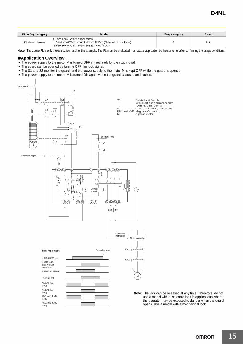
Note: The above PL is only the evaluation result of the example. The PL must be evaluated in an actual application by the customer after confirming the usage conditions.
●Application Overview• The power supply to the motor M is turned OFF immediately by the stop signal.• The guard can be opened by turning OFF the lock signal.• The S1 and S2 monitor the guard, and the power supply to the motor M is kept OFF while the guard is opened.• The power supply to the motor M is turned ON again when the guard is closed and locked.
PL/safety category Model Stop category Reset
PLe/4 equivalentGuard Lock Safety-door Switch
D4NL-@AFG-@, -@A@H-@, -@A@J-@ (Solenoid Lock Type)Safety Relay Unit G9SA-301 (24 VAC/VDC)
0 Auto
Timing Chart
Limit switch S1
S1: Safety Limit Switch with direct opening mechanism (D4B-N, D4N, D4F)
S2: Guard Lock Safety-door SwitchKM1 and KM2: Magnetic ContactorM: 3-phase motor
Guard Lock Safety-door Switch S2Operation signal
Lock signal
K1 and K2(NC)
K1 and K2(NO)
KM1 and KM2(NC)
KM1 and KM2(NO)
Guard opens
TH
SA
PLC
PLC
54
53
34
33
A1 A2 T11 T12
K1
K1
PE T21 T23 T22
K2
K2
6
a
b
123456
JP
13T32T31 23 33 41
25
31
K1
K2
4
ab
ControlCircuit
14 24 34 42A B
KM1
KM2
KM1
KM2
M
KM1 KM2
41
42
12
11
S2
S1
OPEN
12
11
Lock signal
Operation signal
Feedback loop
Operationinstruction
Motor controller
Note: The lock can be released at any time. Therefore, do not use a model with a solenoid lock in applications where the operator may be exposed to danger when the guard opens. Use a model with a mechanical lock.
D4NL
16
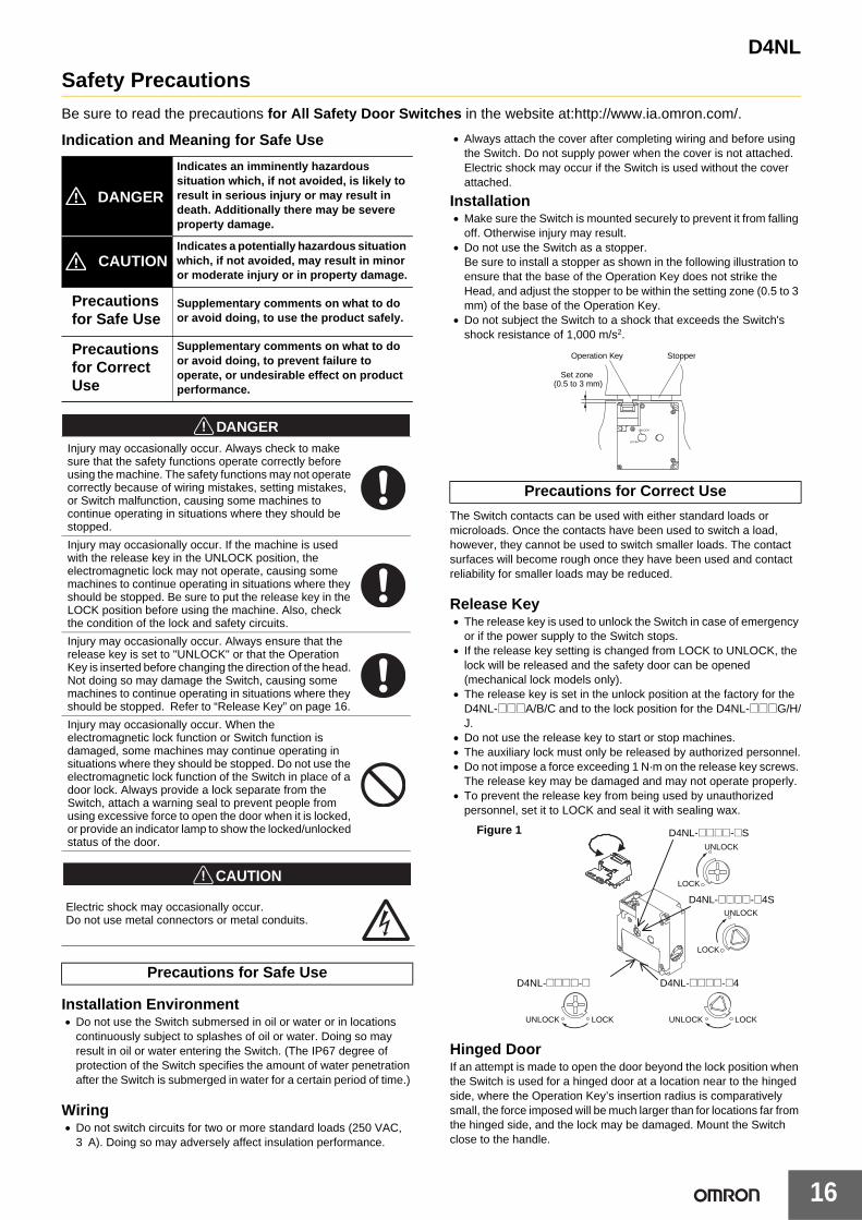
Safety Precautions
Be sure to read the precautions for All Safety Door Switches in the website at:http://www.ia.omron.com/.
Indication and Meaning for Safe Use
!CAUTION
Installation Environment• Do not use the Switch submersed in oil or water or in locations
continuously subject to splashes of oil or water. Doing so may result in oil or water entering the Switch. (The IP67 degree of protection of the Switch specifies the amount of water penetration after the Switch is submerged in water for a certain period of time.)
Wiring• Do not switch circuits for two or more standard loads (250 VAC,
3 A). Doing so may adversely affect insulation performance.
• Always attach the cover after completing wiring and before using the Switch. Do not supply power when the cover is not attached. Electric shock may occur if the Switch is used without the cover attached.
Installation• Make sure the Switch is mounted securely to prevent it from falling
off. Otherwise injury may result.• Do not use the Switch as a stopper.
Be sure to install a stopper as shown in the following illustration to ensure that the base of the Operation Key does not strike the Head, and adjust the stopper to be within the setting zone (0.5 to 3 mm) of the base of the Operation Key.
• Do not subject the Switch to a shock that exceeds the Switch's shock resistance of 1,000 m/s2.
The Switch contacts can be used with either standard loads or microloads. Once the contacts have been used to switch a load, however, they cannot be used to switch smaller loads. The contact surfaces will become rough once they have been used and contact reliability for smaller loads may be reduced.
Release Key• The release key is used to unlock the Switch in case of emergency
or if the power supply to the Switch stops.• If the release key setting is changed from LOCK to UNLOCK, the
lock will be released and the safety door can be opened (mechanical lock models only).
• The release key is set in the unlock position at the factory for the D4NL-@@@A/B/C and to the lock position for the D4NL-@@@G/H/J.
• Do not use the release key to start or stop machines.• The auxiliary lock must only be released by authorized personnel.• Do not impose a force exceeding 1 N·m on the release key screws.
The release key may be damaged and may not operate properly.• To prevent the release key from being used by unauthorized
personnel, set it to LOCK and seal it with sealing wax.
Hinged DoorIf an attempt is made to open the door beyond the lock position when the Switch is used for a hinged door at a location near to the hinged side, where the Operation Key’s insertion radius is comparatively small, the force imposed will be much larger than for locations far from the hinged side, and the lock may be damaged. Mount the Switch close to the handle.
Indicates an imminently hazardous situation which, if not avoided, is likely to result in serious injury or may result in death. Additionally there may be severe property damage.
Indicates a potentially hazardous situation which, if not avoided, may result in minor or moderate injury or in property damage.
Precautions for Safe Use
Supplementary comments on what to do or avoid doing, to use the product safely.
Precautions for Correct Use
Supplementary comments on what to do or avoid doing, to prevent failure to operate, or undesirable effect on product performance.
Injury may occasionally occur. Always check to make sure that the safety functions operate correctly before using the machine. The safety functions may not operate correctly because of wiring mistakes, setting mistakes, or Switch malfunction, causing some machines to continue operating in situations where they should be stopped.
Injury may occasionally occur. If the machine is used with the release key in the UNLOCK position, the electromagnetic lock may not operate, causing some machines to continue operating in situations where they should be stopped. Be sure to put the release key in the LOCK position before using the machine. Also, check the condition of the lock and safety circuits.
Injury may occasionally occur. Always ensure that the release key is set to "UNLOCK" or that the Operation Key is inserted before changing the direction of the head. Not doing so may damage the Switch, causing some machines to continue operating in situations where they should be stopped. Refer to “Release Key” on page 16.
Injury may occasionally occur. When the electromagnetic lock function or Switch function is damaged, some machines may continue operating in situations where they should be stopped. Do not use the electromagnetic lock function of the Switch in place of a door lock. Always provide a lock separate from the Switch, attach a warning seal to prevent people from using excessive force to open the door when it is locked, or provide an indicator lamp to show the locked/unlocked status of the door.
Electric shock may occasionally occur. Do not use metal connectors or metal conduits.
Precautions for Safe Use
DANGER
CAUTION
DANGER
Precautions for Correct Use
UNLOCK
LOCK
StopperOperation Key
Set zone (0.5 to 3 mm)
UNLOCK
LOCK
UNLOCK
LOCK
UNLOCK LOCK UNLOCK LOCK
D4NL-@@@@-@4S
D4NL-@@@@-@S
D4NL-@@@@-@ D4NL-@@@@-@4
Figure 1

D4NL
17
Solenoid Lock ModelsThe solenoid lock locks the door only when power is supplied to the solenoid. Therefore, the door will be unlocked if the power supply to the solenoid stops. Therefore, do not use solenoid lock models for machines that may be operating and dangerous even after the machine stops operating.
MountingAppropriate Tightening Torque• Be sure to tighten each screw of the Switch properly. Loose screws
may result in malfunction.
• When loosening a screw with an electrical screwdriver or similar tool while pressing down on the screw head, do not continue turning the screw past the point where the threads disengage. Doing so may strip the end of the threads.
Switch and Operation Key Mounting• Use M4 screws and washers to mount the Switch and Operation
Key, and tighten the screws to a suitable torque. To ensure safety, use screws that cannot be easily removed or another means to prevent the Switch and Operation Key from easily being removed.
• If the Switch is back-mounted, the release key can be operated only from the bottom and the indicator cannot be used.
• Ensure that the alignment offset between the Operation Key and the key hole does not exceed ±1 mm. If the Operation Key is offset or at an angle, accelerated wear or damage to the Switch may result.
• Observe the specified insertion radius for the Operation Key and insert it in a direction perpendicular to the key hole.
• Do not impose excessive force on the Operation Key while the Key is inserted into the Switch or drop the Switch with the Operation Key inserted. Doing either of these may deform the Key or break the Switch.
Head Direction• Remove the four screws of the head to enable changing the
mounting direction of the head. The head can be mounted in four directions. Ensure that no foreign material enters the interior of the Switch.
• Do not change the head direction with the cover removed.• Do not insert or remove the Operation Key with the Switch head
removed. Doing so may make it impossible to insert the Operation Key.
Attaching a Cover• When attaching a cover, be sure that the seal rubber is in place and
that there is no foreign material present. If the cover is attached with the seal rubber out of place or if foreign material is stuck to the rubber, a proper seal will not be obtained.
• Do not use any screws to connect the cover other than the specified ones. The seal characteristics may be reduced.
Securing the DoorWhen the door is closed (with the Operation Key inserted), the Operation Key may exceed the set zone because of, for example, the door's own weight, machine vibration, or the door cushion rubber. Then, when an attempt is made to open the door, it may result in damage or malfunction. Also, it may not be possible to unlock the Switch if there is weight placed on the Operation Key. Do not rely on the Switch to substitute for a door locking device. Secure the door with a stopper so that the Operation Key remains within the set zone.
Solenoid• The solenoid will heat when it carries current. Do not touch it.• A DC solenoid has polarity. Confirm terminal polarity before wiring
it.
Wiring
Circuit Connection Example for the D4NL-@F@@-B• Direct opening contacts used as safety-circuit inputs are indicated
with the mark. Terminals 11 and 42, and terminals 21 and 22 have direct opening contacts.
• Connect terminals 21 and 22 and terminals 51 and 52 in series when using as safety-circuit inputs (redundancy circuit for terminals 11 and 12 and terminals 41 and 42 below). Connect the terminals individually when using as auxiliary-circuit inputs (e.g., terminals 21 and 22 for safety-door open/closed monitoring and terminals 51 and 52 for monitoring the lock status).
• In the following connection example, terminals 21 and 22 and terminals 51 and 52 are used as auxiliary-circuit inputs.
• Connect the indicators in parallel to the auxiliary circuits or terminals E1 and E2 (D4NL-@@@A-B, -@@@G-B, -@@@B-B, and -@@@H-B only). Connecting to contacts with direct opening mechanisms may result in short-circuit current flowing if the indicator is destroyed, possibly resulting in incorrect equipment operation.
Type Appropriate tightening torque
Terminal screw 0.59 to 0.78 N·m
Cover mounting screw 0.49 to 0.69 N·m
Head mounting screw 0.49 to 0.59 N·m
Operation Key mounting screw 2.35 to 2.75 N·m
Switch mounting screw 0.49 to 0.69 N·m
Connector 1.77 to 2.16 N·m
Cap screw 1.27 to 1.67 N·m
Horizontal/Vertical Mounting (D4DS-K1/-K2)
Adjustable Mounting: Horizontal (D4DS-K3)
Adjustable Mounting: Horizontal/Vertical(D4DS-K5)
40 ±0.1
Two, M4
15 ±0.1
Two, M4
Mounting Holes for Switches Mounting Holes for Operation Keys
Three, M4
79±0.1
32±0.1
55±0.1
41±0.1 or, 43±0.1
Two, M4
Operation key
Set zone (0.5 to 3 mm)
42 11
21
33
E1 (+)
O1 O2
12 41
51
52
22
34
E2 (−)
Indicator (Orange)
Safety circuit
Auxiliary circuit
Auxiliary circuit
Auxiliary circuit
D4NL
18
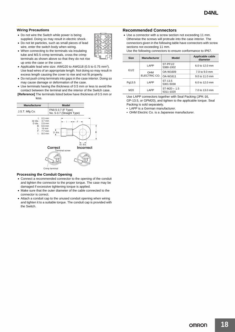
Wiring Precautions• Do not wire the Switch while power is being
supplied. Doing so may result in electric shock.• Do not let particles, such as small pieces of lead
wire, enter the switch body when wiring.• When connecting to the terminals via insulating
tube and M3.5 crimp terminals, cross the crimp terminals as shown above so that they do not rise up onto the case or the cover.
• Applicable lead wire size: AWG20 to AWG18 (0.5 to 0.75 mm2).Use lead wires of an appropriate length. Not doing so may result in excess length causing the cover to rise and not fit properly.
• Do not push crimp terminals into gaps in the case interior. Doing so may cause damage or deformation of the case.
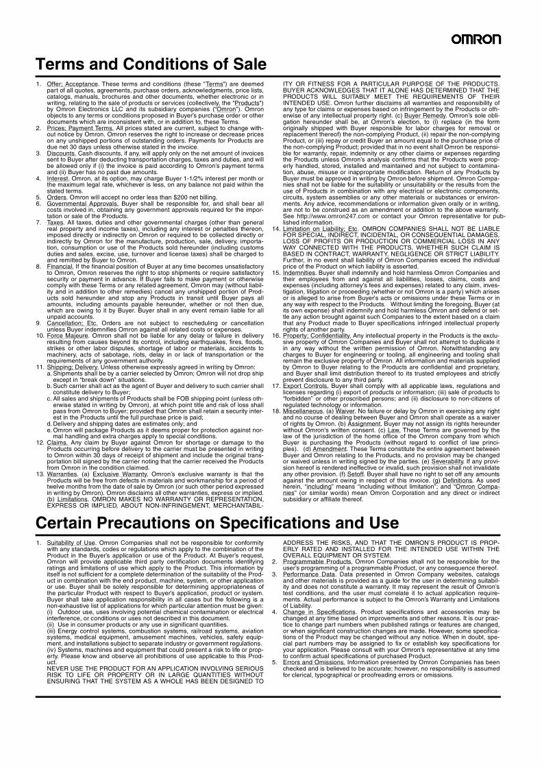
• Use terminals having the thickness of 0.5 mm or less to avoid the contact between the terminal and the interior of the Switch case.
[Reference] The terminals listed below have thickness of 0.5 mm or less.
Processing the Conduit Opening• Connect a recommended connector to the opening of the conduit
and tighten the connector to the proper torque. The case may be damaged if excessive tightening torque is applied.
• Make sure that the outer diameter of the cable connected to the connector is correct.
• Attach a conduit cap to the unused conduit opening when wiring and tighten it to a suitable torque. The conduit cap is provided with the Switch.
Recommended Connectors• Use a connector with a screw section not exceeding 11 mm.
Otherwise the screws will protrude into the case interior. The connectors given in the following table have connectors with screw sections not exceeding 11 mm.Use the following connectors to ensure conformance to IP67.
Use LAPP connectors together with Seal Packing (JPK-16, GP-13.5, or GPM20), and tighten to the applicable torque. Seal Packing is sold separately.• LAPP is a German manufacturer.• OHM Electric Co. is a Japanese manufacturer.
Manufacturer Model
J.S.T. Mfg Co. FN0.5-3.7 (F Type)No. 5-3.7 (Straight Type)
D dia.
dz dia.
Size Manufacturer Model Applicable cable diameter
G1/2
LAPP ST-PF1/25380-1002
6.0 to 12.0 mm
OHM ELECTRIC CO.
OA-W1609 7.0 to 9.0 mm
OA-W1611 9.0 to 11.0 mm
Pg13.5 LAPPST-13.55301-5030 6.0 to 12.0 mm
M20 LAPPST-M20 × 1.55311-1020 7.0 to 13.0 mm
Terms and Conditions of Sale1. Offer; Acceptance. These terms and conditions (these "Terms") are deemed
part of all quotes, agreements, purchase orders, acknowledgments, price lists,catalogs, manuals, brochures and other documents, whether electronic or inwriting, relating to the sale of products or services (collectively, the "Products")by Omron Electronics LLC and its subsidiary companies (“Omron”). Omronobjects to any terms or conditions proposed in Buyer’s purchase order or otherdocuments which are inconsistent with, or in addition to, these Terms.
2. Prices; Payment Terms. All prices stated are current, subject to change with-out notice by Omron. Omron reserves the right to increase or decrease priceson any unshipped portions of outstanding orders. Payments for Products aredue net 30 days unless otherwise stated in the invoice.
3. Discounts. Cash discounts, if any, will apply only on the net amount of invoicessent to Buyer after deducting transportation charges, taxes and duties, and willbe allowed only if (i) the invoice is paid according to Omron’s payment termsand (ii) Buyer has no past due amounts.
4. Interest. Omron, at its option, may charge Buyer 1-1/2% interest per month orthe maximum legal rate, whichever is less, on any balance not paid within thestated terms.
5. Orders. Omron will accept no order less than $200 net billing. 6. Governmental Approvals. Buyer shall be responsible for, and shall bear all
costs involved in, obtaining any government approvals required for the impor-tation or sale of the Products.
7. Taxes. All taxes, duties and other governmental charges (other than generalreal property and income taxes), including any interest or penalties thereon,imposed directly or indirectly on Omron or required to be collected directly orindirectly by Omron for the manufacture, production, sale, delivery, importa-tion, consumption or use of the Products sold hereunder (including customsduties and sales, excise, use, turnover and license taxes) shall be charged toand remitted by Buyer to Omron.
8. Financial. If the financial position of Buyer at any time becomes unsatisfactoryto Omron, Omron reserves the right to stop shipments or require satisfactorysecurity or payment in advance. If Buyer fails to make payment or otherwisecomply with these Terms or any related agreement, Omron may (without liabil-ity and in addition to other remedies) cancel any unshipped portion of Prod-ucts sold hereunder and stop any Products in transit until Buyer pays allamounts, including amounts payable hereunder, whether or not then due,which are owing to it by Buyer. Buyer shall in any event remain liable for allunpaid accounts.
9. Cancellation; Etc. Orders are not subject to rescheduling or cancellationunless Buyer indemnifies Omron against all related costs or expenses.
10. Force Majeure. Omron shall not be liable for any delay or failure in deliveryresulting from causes beyond its control, including earthquakes, fires, floods,strikes or other labor disputes, shortage of labor or materials, accidents tomachinery, acts of sabotage, riots, delay in or lack of transportation or therequirements of any government authority.
11. Shipping; Delivery. Unless otherwise expressly agreed in writing by Omron:a. Shipments shall be by a carrier selected by Omron; Omron will not drop ship
except in “break down” situations.b. Such carrier shall act as the agent of Buyer and delivery to such carrier shall
constitute delivery to Buyer;c. All sales and shipments of Products shall be FOB shipping point (unless oth-
erwise stated in writing by Omron), at which point title and risk of loss shallpass from Omron to Buyer; provided that Omron shall retain a security inter-est in the Products until the full purchase price is paid;
d. Delivery and shipping dates are estimates only; ande. Omron will package Products as it deems proper for protection against nor-
mal handling and extra charges apply to special conditions.12. Claims. Any claim by Buyer against Omron for shortage or damage to the
Products occurring before delivery to the carrier must be presented in writingto Omron within 30 days of receipt of shipment and include the original trans-portation bill signed by the carrier noting that the carrier received the Productsfrom Omron in the condition claimed.
13. Warranties. (a) Exclusive Warranty. Omron’s exclusive warranty is that theProducts will be free from defects in materials and workmanship for a period oftwelve months from the date of sale by Omron (or such other period expressedin writing by Omron). Omron disclaims all other warranties, express or implied.(b) Limitations. OMRON MAKES NO WARRANTY OR REPRESENTATION,EXPRESS OR IMPLIED, ABOUT NON-INFRINGEMENT, MERCHANTABIL-
ITY OR FITNESS FOR A PARTICULAR PURPOSE OF THE PRODUCTS.BUYER ACKNOWLEDGES THAT IT ALONE HAS DETERMINED THAT THEPRODUCTS WILL SUITABLY MEET THE REQUIREMENTS OF THEIRINTENDED USE. Omron further disclaims all warranties and responsibility ofany type for claims or expenses based on infringement by the Products or oth-erwise of any intellectual property right. (c) Buyer Remedy. Omron’s sole obli-gation hereunder shall be, at Omron’s election, to (i) replace (in the formoriginally shipped with Buyer responsible for labor charges for removal orreplacement thereof) the non-complying Product, (ii) repair the non-complyingProduct, or (iii) repay or credit Buyer an amount equal to the purchase price ofthe non-complying Product; provided that in no event shall Omron be responsi-ble for warranty, repair, indemnity or any other claims or expenses regardingthe Products unless Omron’s analysis confirms that the Products were prop-erly handled, stored, installed and maintained and not subject to contamina-tion, abuse, misuse or inappropriate modification. Return of any Products byBuyer must be approved in writing by Omron before shipment. Omron Compa-nies shall not be liable for the suitability or unsuitability or the results from theuse of Products in combination with any electrical or electronic components,circuits, system assemblies or any other materials or substances or environ-ments. Any advice, recommendations or information given orally or in writing,are not to be construed as an amendment or addition to the above warranty.See http://www.omron247.com or contact your Omron representative for pub-lished information.
14. Limitation on Liability; Etc. OMRON COMPANIES SHALL NOT BE LIABLEFOR SPECIAL, INDIRECT, INCIDENTAL, OR CONSEQUENTIAL DAMAGES,LOSS OF PROFITS OR PRODUCTION OR COMMERCIAL LOSS IN ANYWAY CONNECTED WITH THE PRODUCTS, WHETHER SUCH CLAIM ISBASED IN CONTRACT, WARRANTY, NEGLIGENCE OR STRICT LIABILITY.Further, in no event shall liability of Omron Companies exceed the individualprice of the Product on which liability is asserted.
15. Indemnities. Buyer shall indemnify and hold harmless Omron Companies andtheir employees from and against all liabilities, losses, claims, costs andexpenses (including attorney's fees and expenses) related to any claim, inves-tigation, litigation or proceeding (whether or not Omron is a party) which arisesor is alleged to arise from Buyer's acts or omissions under these Terms or inany way with respect to the Products. Without limiting the foregoing, Buyer (atits own expense) shall indemnify and hold harmless Omron and defend or set-tle any action brought against such Companies to the extent based on a claimthat any Product made to Buyer specifications infringed intellectual propertyrights of another party.
16. Property; Confidentiality. Any intellectual property in the Products is the exclu-sive property of Omron Companies and Buyer shall not attempt to duplicate itin any way without the written permission of Omron. Notwithstanding anycharges to Buyer for engineering or tooling, all engineering and tooling shallremain the exclusive property of Omron. All information and materials suppliedby Omron to Buyer relating to the Products are confidential and proprietary,and Buyer shall limit distribution thereof to its trusted employees and strictlyprevent disclosure to any third party.
17. Export Controls. Buyer shall comply with all applicable laws, regulations andlicenses regarding (i) export of products or information; (iii) sale of products to“forbidden” or other proscribed persons; and (ii) disclosure to non-citizens ofregulated technology or information.
18. Miscellaneous. (a) Waiver. No failure or delay by Omron in exercising any rightand no course of dealing between Buyer and Omron shall operate as a waiverof rights by Omron. (b) Assignment. Buyer may not assign its rights hereunderwithout Omron's written consent. (c) Law. These Terms are governed by thelaw of the jurisdiction of the home office of the Omron company from whichBuyer is purchasing the Products (without regard to conflict of law princi-ples). (d) Amendment. These Terms constitute the entire agreement betweenBuyer and Omron relating to the Products, and no provision may be changedor waived unless in writing signed by the parties. (e) Severability. If any provi-sion hereof is rendered ineffective or invalid, such provision shall not invalidateany other provision. (f) Setoff. Buyer shall have no right to set off any amountsagainst the amount owing in respect of this invoice. (g) Definitions. As usedherein, “including” means “including without limitation”; and “Omron Compa-nies” (or similar words) mean Omron Corporation and any direct or indirectsubsidiary or affiliate thereof.
Certain Precautions on Specifications and Use1. Suitability of Use. Omron Companies shall not be responsible for conformity
with any standards, codes or regulations which apply to the combination of theProduct in the Buyer’s application or use of the Product. At Buyer’s request,Omron will provide applicable third party certification documents identifyingratings and limitations of use which apply to the Product. This information byitself is not sufficient for a complete determination of the suitability of the Prod-uct in combination with the end product, machine, system, or other applicationor use. Buyer shall be solely responsible for determining appropriateness ofthe particular Product with respect to Buyer’s application, product or system.Buyer shall take application responsibility in all cases but the following is anon-exhaustive list of applications for which particular attention must be given:(i) Outdoor use, uses involving potential chemical contamination or electricalinterference, or conditions or uses not described in this document.(ii) Use in consumer products or any use in significant quantities. (iii) Energy control systems, combustion systems, railroad systems, aviationsystems, medical equipment, amusement machines, vehicles, safety equip-ment, and installations subject to separate industry or government regulations. (iv) Systems, machines and equipment that could present a risk to life or prop-erty. Please know and observe all prohibitions of use applicable to this Prod-uct. NEVER USE THE PRODUCT FOR AN APPLICATION INVOLVING SERIOUSRISK TO LIFE OR PROPERTY OR IN LARGE QUANTITIES WITHOUTENSURING THAT THE SYSTEM AS A WHOLE HAS BEEN DESIGNED TO
ADDRESS THE RISKS, AND THAT THE OMRON’S PRODUCT IS PROP-ERLY RATED AND INSTALLED FOR THE INTENDED USE WITHIN THEOVERALL EQUIPMENT OR SYSTEM.
2. Programmable Products. Omron Companies shall not be responsible for theuser’s programming of a programmable Product, or any consequence thereof.
3. Performance Data. Data presented in Omron Company websites, catalogsand other materials is provided as a guide for the user in determining suitabil-ity and does not constitute a warranty. It may represent the result of Omron’stest conditions, and the user must correlate it to actual application require-ments. Actual performance is subject to the Omron’s Warranty and Limitationsof Liability.
4. Change in Specifications. Product specifications and accessories may bechanged at any time based on improvements and other reasons. It is our prac-tice to change part numbers when published ratings or features are changed,or when significant construction changes are made. However, some specifica-tions of the Product may be changed without any notice. When in doubt, spe-cial part numbers may be assigned to fix or establish key specifications foryour application. Please consult with your Omron’s representative at any timeto confirm actual specifications of purchased Product.
5. Errors and Omissions. Information presented by Omron Companies has beenchecked and is believed to be accurate; however, no responsibility is assumedfor clerical, typographical or proofreading errors or omissions.

OMRON CANADA, INC. • HEAD OFFICEToronto, ON, Canada • 416.286.6465 • 866.986.6766 • www.omron247.com
OMRON ELECTRONICS DE MEXICO • HEAD OFFICEMéxico DF • 52.55.59.01.43.00 • 01-800-226-6766 • [email protected]
OMRON ELECTRONICS DE MEXICO • SALES OFFICEApodaca, N.L. • 52.81.11.56.99.20 • 01-800-226-6766 • [email protected]
OMRON ELETRÔNICA DO BRASIL LTDA • HEAD OFFICESão Paulo, SP, Brasil • 55.11.2101.6300 • www.omron.com.br
OMRON ARGENTINA • SALES OFFICECono Sur • 54.11.4783.5300
OMRON CHILE • SALES OFFICESantiago • 56.9.9917.3920
OTHER OMRON LATIN AMERICA SALES54.11.4783.5300
Authorized Distributor:
C35I-E-02 07/15 Note: Specifications are subject to change. © 2015 Omron Electronics LLC Printed in U.S.A.
Printed on recycled paper.
Automation Control Systems• Machine Automation Controllers (MAC) • Programmable Controllers (PLC) • Operator interfaces (HMI) • Distributed I/O • Software
Drives & Motion Controls • Servo & AC Drives • Motion Controllers & Encoders
Temperature & Process Controllers • Single and Multi-loop Controllers
Sensors & Vision• Proximity Sensors • Photoelectric Sensors • Fiber-Optic Sensors• Amplified Photomicrosensors • Measurement Sensors• Ultrasonic Sensors • Vision Sensors
Industrial Components • RFID/Code Readers • Relays • Pushbuttons & Indicators• Limit and Basic Switches • Timers • Counters • Metering Devices • Power Supplies
Safety • Laser Scanners • Safety Mats • Edges and Bumpers • Programmable Safety
Controllers • Light Curtains • Safety Relays • Safety Interlock Switches
OMRON AUTOMATION AND SAFETY • THE AMERICAS HEADQUARTERS • Chicago, IL USA • 847.843.7900 • 800.556.6766 • www.omron247.com
OMRON EUROPE B.V. • Wegalaan 67-69, NL-2132 JD, Hoofddorp, The Netherlands. • +31 (0) 23 568 13 00 • www.industrial.omron.eu


![Guard Lock Safety-door Switch D4BL - Mouser Electronics1]-190508.pdf · K3 and K4 (NC) K3 and K4 (NO) KM1 and KM2 (NC) KM1 and KM2 (NO) Operation instruction Lock release signal Lock](https://static.fdocuments.net/doc/165x107/5c9dddbe88c993cb368ba3c5/guard-lock-safety-door-switch-d4bl-mouser-1-190508pdf-k3-and-k4-nc-k3.jpg)