
d-lab.2, d-lab.2plus, netlab -...
78
Operation Manual Digital Minilabs Installation Order number DD+18060252D0 Edition 2005-05-01 Version English, 05034_00 d-lab.2: 8060/260, 8060/803, 8060/804, 8060/270, 8060/272, 8060/157 + 8060/255 d-lab.2plus: 8060/261 8060/813, 8060/814 8060/271, 8060/273 8060/158 + 8060/255 netlab.2plus: 8060/505
Transcript of d-lab.2, d-lab.2plus, netlab -...

Operation Manual
Digital Minilabs
Installation Order number DD+18060252D0 Edition 2005-05-01 Version English, 05034_00
d-lab.2: 8060/260, 8060/803, 8060/804, 8060/270, 8060/272, 8060/157 + 8060/255
d-lab.2plus: 8060/261 8060/813, 8060/814 8060/271, 8060/273 8060/158 + 8060/255
netlab.2plus: 8060/505

Modification History
Version Edition Modifications
05034_00 2005_05_01 Combination of the Operation Manual – Installation for the machines d-lab.2, d-lab.2plus, and netlab.2plus
© 2005 AgfaPhoto GmbH. Alle Rechte vorbehalten.
No part of these instructions may be reproduced, copied, or transmitted in any form or by any means without prior written permission by AgfaPhoto GmbH.
AgfaPhoto is used under license of Agfa-Gevaert AG

d-lab.2, d-lab.2plus, netlab.2plus: Installation Contents
AgfaPhoto 2005-05-01 / PN 05034_00 i
Contents
1 Introduction..........................................................................................................................1 1.1 Available Documentation ..............................................................................................................................................1 1.2 Guideline for the User .....................................................................................................................................................2 1.3 Conventions ........................................................................................................................................................................3
1.3.1 Pictographs ......................................................................................................................................................3 1.3.2 Text styles.........................................................................................................................................................3
2 Transporting the Machine......................................................................................................4 2.1 Principal Information .......................................................................................................................................................4 2.2 Weight of the System Components...........................................................................................................................4 2.3 Directives for Transport of the Machine Components to Other Floors (Vertical Transport)..................4
2.3.1 Auxiliary Equipment .....................................................................................................................................4 2.3.2 Transporting Packed Components ..........................................................................................................5 2.3.3 Transporting Unpacked Components.....................................................................................................6
3 Unpacking the Machine.........................................................................................................8 3.1 Pushing the Machines off the Pallet .........................................................................................................................8 3.2 Mounting Adjusting Feet and Stands ........................................................................................................................9 3.3 Printer ................................................................................................................................................................................. 10
4 Installing the Machine.........................................................................................................18 4.1 Installing the Paper Processor .................................................................................................................................. 18 4.2 Removing the Transport Protections ...................................................................................................................... 20
4.2.1 Print Machine (PM; d-lab.2plus/netlab.2plus) resp. Print Engine (PE ; d-lab.2) ................. 20 4.2.2 Scanner
Applies only to d-lab.2/2plus ..................................................................................................................... 24 4.2.3 Transport Section / Feeder Unit (FU)
Applies only to d-lab.2plus/netlab.2plus ................................................................................................. 25 4.3 Connecting Printer and Paper Processor .............................................................................................................. 26 4.4 Mounting the Table Top and Additional Work Table (Optional)................................................................... 32 4.5 Mounting the Film Brush and Film Takeup
Applies only to d-lab.2/2plus ......................................................................................................................................... 35 4.6 Mounting the Sorter on the Paper Processor ...................................................................................................... 35 4.7 Mounting the Deposit for Large Prints................................................................................................................... 36 4.8 Mounting the Zoom lens (optional)
Applies only to d-lab.2 ..................................................................................................................................................... 37 4.9 Connecting the LCD Screen (Optional) or CRT Monitor .................................................................................. 38 4.10 Connecting the Drive Bay
Applies only to d-lab.2plus/netlab.2plus..................................................................................................................... 40 4.11 Inserting the Ink Ribbon for the Back Printer ..................................................................................................... 41
5 Configuring the Power Supply..............................................................................................43 5.1 Selecting Mains Voltage and Connection Type, Connecting the Power Cable ..................................... 44 5.2 Adapt the Paper Processor to 50Hz / 60Hz......................................................................................................... 46 5.3 Checking the Dryer Power Supply........................................................................................................................... 47 5.4 Connecting the Machine to the Mains .................................................................................................................. 47
6 Mixing Chemicals................................................................................................................48 6.1 Safety Instructions......................................................................................................................................................... 48 6.2 Chemical Sets.................................................................................................................................................................. 50 6.3 Mixing Chemical Solutions (MSC/d-lab Chemicals) ........................................................................................ 51 6.4 Mixing Replenisher Chemicals (d-lab.2 Easy Paper Box)................................................................................ 55

Contents d-lab.2, d-lab.2plus, netlab.2plus: Installation
ii 2005-05-01 / PN 05034_00 AgfaPhotoPhoto
7 Putting the Machine in Operation ........................................................................................ 57 7.1 Switching on the Minilab............................................................................................................................................ 57 7.2 Checking the Software of the Paper Processor .................................................................................................. 59 7.3 Entering Correction Values for the Paper Processor Temperatures and Pumps .................................... 60 7.4 Setting the Replenishment Rates............................................................................................................................ 61 7.5 Setting Temperatures and Calibrating Sensors .................................................................................................. 62 7.6 Calibrating the Water Pumps.................................................................................................................................... 64 7.7 Brief Information for Operators during Warm-Up .............................................................................................. 68 7.8 Checking the Process................................................................................................................................................... 68
8 Preparing the Machine for Production.................................................................................. 70 8.1 Entering the Settings.................................................................................................................................................... 70 8.2 Calibrating the Machine and Running Tests ....................................................................................................... 71
9 Installation report............................................................................................................... 72 10 Index.................................................................................................................................. 73

d-lab.2, d-lab.2plus, netlab.2plus: Installation Introduction
AgfaPhoto 2005-05-01 / PN 05034_00 1
1 Introduction
1.1 Available Documentation
The complete Operation and Service Manual comprises of several documents (see table below).
The customer receives the “Preinstallation” instructions when the machine is ordered.
The Operation Manuals “Installation” and “Operation” are included with the machine shipment. The “Operation” folder includes a CD with the complete Operation Manual (except circuit diagrams).
All other sections of the Operation and Service Manual can be ordered from AgfaPhoto.
The Operation Manuals “Installation” and “Operation” must be kept around the machine to ensure that all users have access to these instructions.
Operation Manuals Owner Photo-Assistant
Technician
Operation ●
Installation ● ●
Service Manuals Owner Photo-Assistant
Technician
Repair ●
Parts List ● ●
Circuit Diagrams ●
Preinstallation ●
The Operation Manual Installation applies to the following machines:
Machines with gas laser:
d-lab.2 type 8060/260
d-lab.2plus type 8060/261
Machines with solid state laser:
d-lab.2 select type 8060/803 and type 8060/804
d-lab.2 basic type 8060/270 and type 8060/272
d-lab.2 (70mm) type 8060/157 + 8060/255
d-lab.2plus select type 8060/813 and type 8060/814
d-lab.2plus basic type 8060/271 and type 8060/273
d-lab.2plus (70mm) type 8060/158 + 8060/255
netlab.2plus basic type 8060/505

Introduction d-lab.2, d-lab.2plus, netlab.2plus: Installation
2 2005-05-01 / PN 05034_00 AgfaPhoto
1.2 Guideline for the User
Operation / Service Manual Information
Preinstallation
The owner takes care of the listed preinstallation measures and returns the checklist to AgfaPhoto no later than two weeks prior to the installation date.
Installation The machine is delivered by a forwarding company.
This “Installation” section of the Operation Manual describes the transport to the installation site, as well as the installation and implementation of the machine.
The machine is installed by an AgfaPhoto authorized technician and put in operation.
Operation The “Operation” section of the Operation Manual includes all important information required to ensure operation by a photo-assistant:
Chapter 1: Notes on the Operation Manual, legal notes, safety notes, transport and storage.
Chapter 2: Introduction of the components, functions and controls of the machine, help function and information.
Chapter 3: Description of the mixing process for chemicals.
Chapter 4: Prior to production the Minilab must be set up to meet the requirements of the laboratory (machine settings) and the order handling (print configurations).
Chapter 5: Description of the tests, which ensure the production quality.
Chapter 6: Step by step description of the order handling.
Chapter 7: Description of possible problems, which may be solved by the customer.
Chapter 8: Description of the required maintenance routines on the machine.
Chapter 9: Listing of the technical specifications of the Minilab.
Chapter 10: Description of measures for environmental protection and the disposal of the machine.
Chapter 11: Description of measures for closing down a machine.
Chapter 12: Explanation of the abbreviations and special terms used in these instructions.
Chapter 13: Key Word Index
Chapter 14: Appendix

d-lab.2, d-lab.2plus, netlab.2plus: Installation Introduction
AgfaPhoto 2005-05-01 / PN 05034_00 3
1.3 Conventions
1.3.1 Pictographs
The icons, keywords, and set off text passages in the instructions have the following meaning:
Operating steps
Note
Indicates additional information on the respective subject or the possibility of operating errors.
CAUTION!
This indicates a potential danger which may result in medium or minor personal injuries or property damage.
WARNING!
Indicates a possible risk involved with a product which in case of non-observance may result in severe personal injuries or even death.
Special tools
1.3.2 Text styles
The following text passages are emphasized by bold print / italic print in this manual:
1. Screen designations Example: Pressing OK will validate the displayed text and close the dialog window.
2. Button designations Example: Press the Reorder button to edit reorders.
3. Italic print is used for reference to chapters or paragraphs. Example: See paragraphs Menu Overview and Screen Structure on the following pages.
Transporting the Machine d-lab.2, d-lab.2plus, netlab.2plus: Installation
4 2005-05-01 / PN 05034_00 AgfaPhoto
2 Transporting the Machine
2.1 Principal Information
The Minilab always consists of two system components, the Printer and the Paper Processor. The components are separately packed for transport to the customer.
The Minilab components may be transported by a fork lift or low lift platform truck either still packed or unpacked. The unpacked components have castors. By means of these castors the components can be transported for a short distance and on even floors to the installation site.
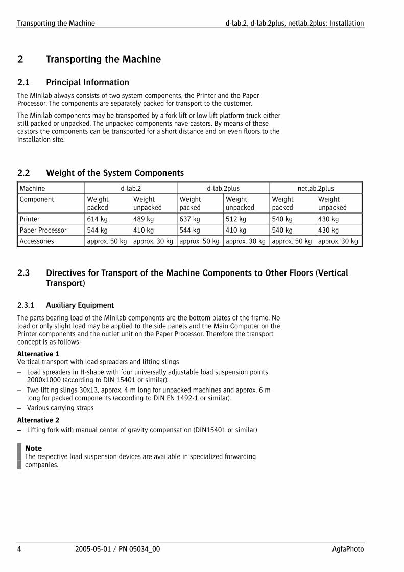
2.2 Weight of the System Components
Machine d-lab.2 d-lab.2plus netlab.2plus
Component Weight packed
Weight unpacked
Weight packed
Weight unpacked
Weight packed
Weight unpacked
Printer 614 kg 489 kg 637 kg 512 kg 540 kg 430 kg
Paper Processor 544 kg 410 kg 544 kg 410 kg 540 kg 430 kg
Accessories approx. 50 kg approx. 30 kg approx. 50 kg approx. 30 kg approx. 50 kg approx. 30 kg
2.3 Directives for Transport of the Machine Components to Other Floors (Vertical Transport)
2.3.1 Auxiliary Equipment
The parts bearing load of the Minilab components are the bottom plates of the frame. No load or only slight load may be applied to the side panels and the Main Computer on the Printer components and the outlet unit on the Paper Processor. Therefore the transport concept is as follows:
Alternative 1 Vertical transport with load spreaders and lifting slings
– Load spreaders in H-shape with four universally adjustable load suspension points 2000x1000 (according to DIN 15401 or similar).
– Two lifting slings 30x13, approx. 4 m long for unpacked machines and approx. 6 m long for packed components (according to DIN EN 1492-1 or similar).
– Various carrying straps
Alternative 2
– Lifting fork with manual center of gravity compensation (DIN15401 or similar)
Note The respective load suspension devices are available in specialized forwarding companies.

d-lab.2, d-lab.2plus, netlab.2plus: Installation Transporting the Machine
AgfaPhoto 2005-05-01 / PN 05034_00 5
2.3.2 Transporting Packed Components
We recommend to transport the packed components since the packing material protects sensitive parts. The drawings show the arrangement of the load suspension devices:
1
32
dlab2609
1 Load spreader
2 Lifting sling
3 Printer component, packed
The lifting slings are positioned against the inner edge of the outer pallet feet. They should clamp the box slightly at the upper side.
Straps around the upper and lower part of the box ensure that the box cannot slip out of the lifting slings (straps not shown).
In case of pallets without feet but with skids, i.e. wooden bars, the lifting slings should be inserted in the recesses of the wooden bars.

Transporting the Machine d-lab.2, d-lab.2plus, netlab.2plus: Installation
6 2005-05-01 / PN 05034_00 AgfaPhoto
2.3.3 Transporting Unpacked Components
Dismount the following parts of the Printer prior to transport:
Table top (already removed in case of a new installation)
Cover of the sheet transfer = ST
Left and right magazine section doors
1
2
3
dlab2610 (Fig. shows d-lab.2)
Paper Processor:
1 Load spreader
2 Spacer bar, both sides
3 Lifting sling
Transport the unpacked components as shown in the figure:
Position the lifting slings, left and right, around the housing between the foot screw and guide castor.
Protect the upper components by a cushioned spacer part on both sides, front and back, of the machine. Suitable are here the felt covered support bars of the Printer box.
0247_005 (Fig. shows netlab.2plus)
Two bars are to be placed in the back of the machine. Adjust the load spreaders in such a way that the lifting slings fix the inserted bars and still leave enough space between the lifting slings and the machine parts on top.

d-lab.2, d-lab.2plus, netlab.2plus: Installation Transporting the Machine
AgfaPhoto 2005-05-01 / PN 05034_00 7
1
2
4
5
3
dlab2607 (Fig. shows d-lab.2)
Printer:
1 Load spreader
2 Table top dismounted
3 Spacer bar from packing box
4 Lifting sling: 2 x 4 m
5 Spacer bar or similar device: 2 x at least 120 mm high
0247_006 (Fig. shows netlab.2plus)

Unpacking the Machine d-lab.2, d-lab.2plus, netlab.2plus: Installation
8 2005-05-01 / PN 05034_00 AgfaPhoto
3 Unpacking the Machine The Printer and the Paper Processor are delivered separately and are joined during installation.
3.1 Pushing the Machines off the Pallet
Proceed with the following steps, one by one, for Printer and Paper Processor (see illustrations on the following pages):
dlabr193
Open the boxes and remove the packing material.
Place the ramp supplied with the Printer on the front side of the pallet.
Remove the holding brackets on the right and left side of the machine with a fork or socket wrench size 16.
Mount the adjusting feet and/or stands (see Mounting adjusting feet and stands on the following page) and unscrew them until they support the machine and the pallet crossbars are free.
Pull out the pallet crossbars (they are not fixed to the pallet).
Turn up the adjusting feet until the machine is standing on its castors.
Push the machine on the ramp and off the pallet.
Push the machine to the installation site.

d-lab.2, d-lab.2plus, netlab.2plus: Installation Unpacking the Machine
AgfaPhoto 2005-05-01 / PN 05034_00 9
3.2 Mounting Adjusting Feet and Stands
Special tools A fork wrench size 16 mm (Paper Processor) and another one size 24 mm (Printer) are needed to adjust the height of the machine.
Before lowering the adjusting feet press the enclosed rubber inserts or discs into the stands:
dlabr092
Printer: In case the stands are not mounted yet to the adjusting feet: Position the stands under the adjusting feet, unscrew the feet until the ball joints are in the stands.
Paper Processor: Press the discs into the stands. Then position the stands below the adjusting screws for the adjustment of the Paper Processor height.

Unpacking the Machine d-lab.2, d-lab.2plus, netlab.2plus: Installation
10 2005-05-01 / PN 05034_00 AgfaPhoto
3.3 Printer Applies to d-lab.2/2plus
4
56
7
2
1
3
8
9
dlab2637 (Fig. shows d-lab.2)

d-lab.2, d-lab.2plus, netlab.2plus: Installation Unpacking the Machine
AgfaPhoto 2005-05-01 / PN 05034_00 11
12
14
11
10
15
13
dlab2638 (Fig. shows d-lab.2)

Unpacking the Machine d-lab.2, d-lab.2plus, netlab.2plus: Installation
12 2005-05-01 / PN 05034_00 AgfaPhoto
Applies to netlab.2plus
0247_027

d-lab.2, d-lab.2plus, netlab.2plus: Installation Unpacking the Machine
AgfaPhoto 2005-05-01 / PN 05034_00 13
0247_028

Unpacking the Machine d-lab.2, d-lab.2plus, netlab.2plus: Installation
14 2005-05-01 / PN 05034_00 AgfaPhoto
Paper Processor
Applies to d-lab.2/2plus
2
1
3
4
5
6
7
8
11
1312
dlab2617 (Fig. shows d-lab.2)

d-lab.2, d-lab.2plus, netlab.2plus: Installation Unpacking the Machine
AgfaPhoto 2005-05-01 / PN 05034_00 15
15
14
18
19
21
20
17
16
dlab2618 (Fig. shows d-lab.2)

Unpacking the Machine d-lab.2, d-lab.2plus, netlab.2plus: Installation
16 2005-05-01 / PN 05034_00 AgfaPhoto
Applies to netlab.2plus
0247_003

d-lab.2, d-lab.2plus, netlab.2plus: Installation Unpacking the Machine
AgfaPhoto 2005-05-01 / PN 05034_00 17
0247_004

Installing the Machine d-lab.2, d-lab.2plus, netlab.2plus: Installation
18 2005-05-01 / PN 05034_00 AgfaPhoto
4 Installing the Machine Tools required for the installation of the machine:
– Set of long Allan keys with ball head (2 – 8 mm)
– Fork wrench size 10, 13, 16, 19, 24 (size 10 and 19 to attach the Printer to the Paper Processor; size 16 and 24 for the adjusting feet)
– Ratchet with inserts to remove the machine components from the transport pallets
– Level (approx. 30 cm long)
– Phillips and slotted screwdrivers, two sizes
– Phase tester
– Multimeter
4.1 Installing the Paper Processor
A spirit level is required to level the machine (length approx. 30 cm).
Note The drive motor frequency must be checked prior to machine startup and adapted to the local supply if necessary (50Hz or 60Hz). The located on the back of the machine. Therefore it can only be checked or adapted in case of sufficient distance from the wall (approx. 60 cm). If the machine is installed closer to the wall make sure to check and/or adapt the motor frequency before the machine is installed (see Drive motor adaptation 50Hz / 60 Hz).
Press the discs into the stands for the adjusting feet and place the stands below the four adjusting feet.
Note The two machine feet in the rear can only be reached from the rear side.
Unscrew the adjusting feet until the castors are 2 to 3 mm away from the floor.
Open the Paper Processors top cover until it engages (only engages in vertical position).

d-lab.2, d-lab.2plus, netlab.2plus: Installation Installing the Machine
AgfaPhoto 2005-05-01 / PN 05034_00 19
Remove all crossovers and put them aside. Do not stack the crossovers so as not to damage the rollers and paper guide surfaces.
Open the rack locks (at the rear edge of the tank section).
Remove the racks one by one, unpack them and insert them again.
Mount the crossovers and lock the racks.
dlab2126
Level the machine by placing a spirit level on top of the processing tank frames, in transport direction and crosswise, and adjusting the machine feet.
dlab2595 (Fig. shows d-lab.2/2plus)
Close the top cover of the Paper Processor. Hold on to the cover with one hand while unlocking it (press PUSH) and then close it.

Installing the Machine d-lab.2, d-lab.2plus, netlab.2plus: Installation
20 2005-05-01 / PN 05034_00 AgfaPhoto
4.2 Removing the Transport Protections
All transport protection devices are orange and must be removed prior to the machine startup.
Keep the transport protections for a further transport later on. They can be stored in the free space below the Printer table top, for example, (see Mounting the table top and additional work table).
4.2.1 Print Machine (PM; d-lab.2plus/netlab.2plus) resp. Print Engine (PE ; d-lab.2)
The exposure unit or print machine is held by a support plate, which is fastened by seven Allan screws (accessible from the side after opening the Printer side door) and by two hex-head screws (accessible from the top after removing the scanner panels and pulling out the main computer).
Lateral transport protections
dlabr093
Open the Printer side door.
Unscrew the seven Allan screws; thereby holding on to the support plate to keep it from dropping.
Take out the plate and put it aside together with the screws (do not turn in screws).

d-lab.2, d-lab.2plus, netlab.2plus: Installation Installing the Machine
AgfaPhoto 2005-05-01 / PN 05034_00 21
Upper transport protections
Applies to d-lab.2/2plus
Remove the panels of the main computer (loosen two screws left and right of the main computer).
Undo the two fastening screws of the PC and pull out the PC until the transport protection screw located below the PC is accessible.
1
2
3
4 5
7
6
G_GG230 (Fig. shows d-lab.2)
Remove the cover of the cartridge feeder (3) (Allan screw size 3).
Remove the lamphouse cover: remove the lamp lid (4) and the filter cover (5); one Phillips screw (6).
Remove the scanner panels: two Philips screws (2 and 7).
1
2
G_GG713
Loosen both transport protection screws (1) and remove them.
Insert the two enclosed black dummy plugs instead.
CAUTION! Without dummy plug light may enter and fog the paper in the Printer section.
Push in the PC and fasten it (do not yet mount the panels).

Installing the Machine d-lab.2, d-lab.2plus, netlab.2plus: Installation
22 2005-05-01 / PN 05034_00 AgfaPhoto
Applies to netlab.2plus
0247_007
Loosen both transport protection screws (1) and remove them.
Insert the two enclosed black dummy plugs instead.
CAUTION! Without dummy plug light may enter and fog the paper in the Printer section.

d-lab.2, d-lab.2plus, netlab.2plus: Installation Installing the Machine
AgfaPhoto 2005-05-01 / PN 05034_00 23
Check the safety screws
dlab2005b
Open the lock of the print machine (PM) (two levers, 1) and pull out the print machine (2).
ri002
Check the safety screws (1) and adjust if necessary:
The distance between screw head and plate should be approx. 2 mm.
The screws must be locked by a nut since otherwise they may tighten on its own. If the screws are too tight, vibrations may be transmitted to the print engine.
These screws are a precaution in case a rubber connection breaks.
Close the Printer side door.

Installing the Machine d-lab.2, d-lab.2plus, netlab.2plus: Installation
24 2005-05-01 / PN 05034_00 AgfaPhoto
4.2.2 Scanner Applies only to d-lab.2/2plus
For transport protection the scanner is mounted on the Printer frame by means of four screws (two in the front and two in the back). The rear screws can only be accessed after the scanner panels have been removed.
dlabi199
If the panels are mounted, remove the panels of the main computer, cartridge feeder, lamphouse, and scanner (see Print machine / upper transport protection).
Unscrew the Allan screws front (see illustration) and back, remove the orange metal brackets and put them aside together with the screws (do not turn the screws back in – do not mount the panels yet).

d-lab.2, d-lab.2plus, netlab.2plus: Installation Installing the Machine
AgfaPhoto 2005-05-01 / PN 05034_00 25
4.2.3 Transport Section / Feeder Unit (FU) Applies only to d-lab.2plus/netlab.2plus
The feeder unit is secured with two transport protections, mounted by two screws each.
1
G_FU114
Open the Printer front door.
Undo the locking lever of the feeder unit and pull out the feeder unit.
Loosen the two transport protections front right and rear right side and put them aside together with the screws (to not turn in the screws again).
Push in the feeder unit, lock it and close the Printer front door.

Installing the Machine d-lab.2, d-lab.2plus, netlab.2plus: Installation
26 2005-05-01 / PN 05034_00 AgfaPhoto
4.3 Connecting Printer and Paper Processor
1. Installing the cable connections Printer / Paper Processor
The Printer cables are taped to the outside on the right.
dlab2262 (Fig. shows d-lab.2/2plus)
Push the Printer to the Paper Processor leaving a distance of approx. 10 cm.

d-lab.2, d-lab.2plus, netlab.2plus: Installation Installing the Machine
AgfaPhoto 2005-05-01 / PN 05034_00 27
dlab2263 (Fig. shows d-lab.2/2plus)
Open the door bottom left side on the Paper Processor.
Remove the drip pan (1) and the metal plate mounted behind drain taps (loosen four screws).
Thread the cables coming from the Printer through the opening in the side panel of the Paper Processor.
Screw the two ground connections to the respective connection points next to the opening in the Paper Processor side panel.
Connect the two Printer cables with the two cables of the Paper Processor (plug connection).
hang up the cables, they must not touch the machine bottom.
CAUTION! Fasten the grounding cables with care!

Installing the Machine d-lab.2, d-lab.2plus, netlab.2plus: Installation
28 2005-05-01 / PN 05034_00 AgfaPhoto
2. Pushing the Printer to the Paper Processor
dlab2267
Push the Printer against the Paper Processor, as close as possible, so that the centering bolts (1) fit in the oblong holes of the Paper Processor (2). The Printer and the Paper Processor should be as close as possible. Pushing them again later on is not possible because of the adjusting feet, which are unscrewed. Make sure that no cables are clamped.
3. Docking Printer and Paper Processor
Printer and Paper Processor are connected by means of two hex-head screws at the bottom (in the right hand compartment for the paper magazine) and three Allan screws on top (in the area of the sheet transfer (ST).
3
1
2
G_GG226 (Fig. shows d-lab.2)
Open the Printer front door.
Pull the button top right (1), lift the cover (2) of the sheet transfer unit (ST) slightly, pull it to the front by a few centimeters and remove it.
Take out the sheet transfer (ST) (3).

d-lab.2, d-lab.2plus, netlab.2plus: Installation Installing the Machine
AgfaPhoto 2005-05-01 / PN 05034_00 29
3
1
2
G_GG126 (Fig. shows d-lab.2plus)
.
3
1
2
G_GG126b (Fig. shows netlab.2plus)

Installing the Machine d-lab.2, d-lab.2plus, netlab.2plus: Installation
30 2005-05-01 / PN 05034_00 AgfaPhoto
dlab2599
Open the plug connection (two screws).
Open the Paper Processors top cover until it engages (only engages in vertical position).
Remove the CD feed roller set and the roller shutter (better view of the transfer angle when the Printer is attached to the Paper Processor).
dlab2057
Open the door to the right hand paper magazine compartment.
Adjust the Printer height by turning the three adjusting feet until the two holes for the hex-head screws (1) are aligned on one level with the corresponding holes of the Paper Processor.
In this position the centering bolts are in the upper position of the oblong holes in the Paper Processor.
Due to the shape of the two screws their shoulders only fit in the holes if Printer and Paper processor are precisely aligned.
For the adjustable foot inside the Printer use an 8 mm Allan key.
Make sure that the Printer is level (if necessary check with a spirit level).
Observe the distance between Printer and Paper Processor, they must be as close as possible.
Tighten the two hex-head screws with a fork wrench size 19.
d-lab.2, d-lab.2plus, netlab.2plus: Installation Installing the Machine
AgfaPhoto 2005-05-01 / PN 05034_00 31
1
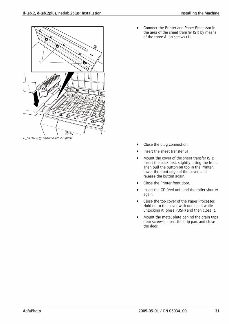
G_ST701 (Fig. shows d-lab.2/2plus)
Connect the Printer and Paper Processor in the area of the sheet transfer (ST) by means of the three Allan screws (1).
Close the plug connection.
Insert the sheet transfer ST.
Mount the cover of the sheet transfer (ST): Insert the back first, slightly lifting the front. Then pull the button on top in the Printer, lower the front edge of the cover, and release the button again.
Close the Printer front door.
Insert the CD feed unit and the roller shutter again.
Close the top cover of the Paper Processor. Hold on to the cover with one hand while unlocking it (press PUSH) and then close it.
Mount the metal plate behind the drain taps (four screws), insert the drip pan, and close the door.

Installing the Machine d-lab.2, d-lab.2plus, netlab.2plus: Installation
32 2005-05-01 / PN 05034_00 AgfaPhoto
4.4 Mounting the Table Top and Additional Work Table (Optional) Applies to d-lab.2/2plus
Remove the panels, if not removed before for a previous step (see Removing transport protections).
Note The room under the table top can be used to store the transport protections.
1
2
3
G_GG227 (Fig. shows d-lab.2)
Mount the table top: Place the table top on the machine and slide it in. The table may have to be tilted a little on the main computer and lifted in the negative carrier area. The screws of the cartridge feeder have to be slackened so that the latter can be lifted a little.
Open the Printer side door, press the pin, which locks the left front door (1) to unlock it, and then open the left front door.
Close the Printer side door.
Fasten the table top with size 5 Allan screws (2 and 3). Access to screw (3) is from inside the scanner unit, for this purpose open the front door.

d-lab.2, d-lab.2plus, netlab.2plus: Installation Installing the Machine
AgfaPhoto 2005-05-01 / PN 05034_00 33
1
2
G_GG128
Mount the additional worktable (1) or put in the stoppers:
Mount the optional additional work table by pushing it into the openings on the left side of the table top (1) and fastening it with the two clamps from below (2) (close the clamps).
If no optional work table is to be mounted, put in the five blind stoppers (included in the accessory pack).
Do not yet close the panels of scanner and main computer.

Installing the Machine d-lab.2, d-lab.2plus, netlab.2plus: Installation
34 2005-05-01 / PN 05034_00 AgfaPhoto
Applies to netlab.2plus
Note The room under the table top can be used to store the transport protections.
1
3
2
G_GG127b
Mount the table top: Attach the table top, just push it in (it is not necessary to remove the computer section).
Open the Printer side door, press the pin, which locks the left front door (1) to unlock it, and then open the left front door.
Close the Printer side door.
Fasten the table top with size 5 Allan screws (2 and 3). Access to screw (3) is from inside the scanner unit, for this purpose open the front door.
1
2
G_GG128b
Mount the additional worktable (1) or put in the stoppers:
Mount the optional additional work table by pushing it into the openings on the left side of the table top (1) and fastening it with the two clamps from below (2) (close the clamps).
If no optional work table is to be mounted, put in the five blind stoppers (included in the accessory pack).

d-lab.2, d-lab.2plus, netlab.2plus: Installation Installing the Machine
AgfaPhoto 2005-05-01 / PN 05034_00 35
4.5 Mounting the Film Brush and Film Takeup Applies only to d-lab.2/2plus
Mount the film cleaning brush in horizontal position and fold up the upper section.
Mount the film takeup: make sure that the film takeup is correctly attached on the left.
4.6 Mounting the Sorter on the Paper Processor
Hang the sorter on two bolts on the Paper Processor and fasten it with one screw. The screw and the two bolts are included in the sorter box.
dlab2504
Hang the two bolts in the lugs on the Paper Processor. The shorter bolt must be inserted in the upper position, with the flat facing up.
Mount the sorter on the hinges.
Connect plug and socket for the drive motor.
Fasten the sorter on the Paper Processor (right hand side wall, 1 screw).

Installing the Machine d-lab.2, d-lab.2plus, netlab.2plus: Installation
36 2005-05-01 / PN 05034_00 AgfaPhoto
4.7 Mounting the Deposit for Large Prints
The deposit tray is included in the accessory pack of the Paper Processor.
dlab2505
Mount the deposit tray and screw it on.

d-lab.2, d-lab.2plus, netlab.2plus: Installation Installing the Machine
AgfaPhoto 2005-05-01 / PN 05034_00 37
4.8 Mounting the Zoom lens (optional) Applies only to d-lab.2
For this, the fixed focus lens must be dismounted.
Slotted and Phillips screwdrivers Allan key size 5
dlabr270
Remove the fan for the CCD cooling (1): 2 screws
Dismount the film chute (2): 4 knurled screws (3)
Remove the fix-focus lens: Loosen 4x size 5 Allan screws (see arrow) on the lens carrier. Thereby press the lens by the handle against so that the lens cannot drop down when the screws are removed. Otherwise it may become useless!
Mount the zoom: Fit 2 cables to the Zoom Controller board. Push the zoom with the handle into the holding pins on the lens carrier and tighten the Allen screws.
Connect the 2 cables on the CCD. To do so turn the CCD manually by approx. 90° to the right until there is access to both sockets. One of them must be screwed.
Fasten the fan and the film chute again.
Adjust the position of the film chute until it fits in the recess in the Printer door!

Installing the Machine d-lab.2, d-lab.2plus, netlab.2plus: Installation
38 2005-05-01 / PN 05034_00 AgfaPhoto
4.9 Connecting the LCD Screen (Optional) or CRT Monitor
Applies to d-lab.2/2plus
dlabr307
Remove the panels of the main computer and the scanner (see Removing the transport protections).
If the access from the back of the machine is not possible, pull out the main computer until you have access to the back of the computer. If there is access form the back, remove the rear panel of the scanner housing (screws).
Connect the VGA cable (15-pin), if applicable the touch-screen cable (9-pin), and the power cable on the monitor.
Thread the VGA cable through the upper cable duct (1) and through the recess to the main computer, and connect it there (socket VGA Monitor).
Connect the touch-screen cable (9-pin) on the interface connector Touch Screen (ST06) behind the main computer (viewed from the machine front).
Connect the power cable on the mains connector behind the main computer.
Applies to d-lab.2 Mount the panels. Applies to d-lab.2plus Do not yet mount the panels (see Connecting the drive bay).

d-lab.2, d-lab.2plus, netlab.2plus: Installation Installing the Machine
AgfaPhoto 2005-05-01 / PN 05034_00 39
Applies to netlab.2plus
0247_014
Remove the rear cover (2) (screws, 1).
0247_015
Connect the VGA cable (15-pin), if applicable the touch-screen cable (9-pin), and the power cable on the monitor.
Connect the VGA cable on the main computer (VGA Monitor connection).
Connect the touch-screen cable (9-pin) on the interface connector Touch Screen (ST06) behind the main computer.
Connect the power cable on the mains connector behind the main computer.

Installing the Machine d-lab.2, d-lab.2plus, netlab.2plus: Installation
40 2005-05-01 / PN 05034_00 AgfaPhoto
4.10 Connecting the Drive Bay Applies only to d-lab.2plus/netlab.2plus
Connect the drive bay with the corresponding three cables. One cable is for the power supply (via the main computer), the other two are for the data transfer.
1
3
G_PC709
Thread the three cables through the upper cable duct and through the opening leading to the main computer, and connect them on the main computer: Power cable (1) in the corresponding socket, USB cables (2,3) into any USB sockets of the computer.
Mount the panels.

d-lab.2, d-lab.2plus, netlab.2plus: Installation Installing the Machine
AgfaPhoto 2005-05-01 / PN 05034_00 41
4.11 Inserting the Ink Ribbon for the Back Printer
Applies to d-lab.2
4
3
2
1
dlab2074
Open the Printer front door.
Unscrew the locking screw (1, red) of the lane distributor (LD).
Pull out the lane distributor on the telescopic rails.
Unscrew the knurled screws (2) and remove the top cover of the back printer.
Prepare the new ink ribbon cartridge: if present remove the foil strip on the ink ribbon, remove the red protection. The ink ribbon must be tight in the cartridge; if necessary tighten by the knob (4) (observe the direction indicated by the arrow).
Insert the ink ribbon cartridge.
Turn the knob (4) of the cartridge until you hear the cartridge engage.
Push in the lane distributor (LD) and tighten the locking screw.
Close the Printer front door.

Installing the Machine d-lab.2, d-lab.2plus, netlab.2plus: Installation
42 2005-05-01 / PN 05034_00 AgfaPhoto
Applies to d-lab.2plus/netlab.2plus
1
3 4
2
G_SD112
Open the Printer front door.
Open the locking lever (1, red) of the sheet distributor (SD).
Pull out the unit on the telescopic rails.
Unscrew the knurled screws (2) and remove the top cover of the back printer.
Prepare the ink ribbon cartridge: if present remove the foil strip on the ink ribbon, remove the red protection. The ink ribbon must be tight in the cartridge; if necessary tighten by the knob (4) (observe the direction indicated by the arrow).
Insert the ink ribbon cartridge.
Turn the knob (4) of the cartridge until you hear the cartridge engage.
Push in the sheet distributor (SD) and close the locking lever.
Close the Printer front door.

d-lab.2, d-lab.2plus, netlab.2plus: Installation Configuring the Power Supply
AgfaPhoto 2005-05-01 / PN 05034_00 43
5 Configuring the Power Supply
CAUTION! The Minilab may not be set to the local connecting condition upon delivery. Therefore checking and conversion of the machine is necessary before the machine is connected with the local power supply. Delivery condition: 230/400 V AC; 50 Hz; 3 phases / neutral
To check and adapt the voltage follow the steps below (see following sections):
– Check and/or set the mains voltage correctly.
– Check and/or set the type of connections (1 phase / 3 phases) correctly.
– Check and/or set the mains frequency (50Hz/60Hz) of the Paper Processor drive motor correctly (50 / 60 Hz).
– Check and/or set the voltage of the dryer correctly.

Configuring the Power Supply d-lab.2, d-lab.2plus, netlab.2plus: Installation
44 2005-05-01 / PN 05034_00 AgfaPhoto
5.1 Selecting Mains Voltage and Connection Type, Connecting the Power Cable
The electrical connection and the power supply unit are located in the Paper Processor. For access remove the right hand side panel.
WARNING! Risk of electric shock. Only qualified professional personnel is permitted to open the side panel and to connect the machine to the lab supply system.
Open the right hand side panel of the Paper Processor: If the sorter is mounted, loosen the screw, which holds the sorter on the Paper Processor, and swivel the sorter to the front.
Overview of connection types
Connection type
Pictograph Nominal supply voltage
Nominal frequency
Nominal current Site connection, fuse protection
3W + N + PE
220/380 V 230/400 V 240/415 V
50/60 Hz 16 A 3 x 16 A
3W + PE
200 V 210 V 220 V 230 V 240 V
50/60 Hz 25 A 3 x 25 A
2W + PE 1W + N + PE
200 V 210 V 220 V 230 V 240 V
50/60 Hz 32 A 1 x 32 A

d-lab.2, d-lab.2plus, netlab.2plus: Installation Configuring the Power Supply
AgfaPhoto 2005-05-01 / PN 05034_00 45
TB 1 L1 L2 L3
L
PE
PEN
PEL1 L2 L3
L1 L2 L3
N
N
TB2
TB1
TB4
N
2
N N
2
N
2
3
2
2
1
1
32
1
1
1
1
1
1
1 3
3
4 5 6
6
7 8
8
9
9
10
10754
1
2
dlab2287
1 Jumper
2 Power supply cable
Ø Phase
W Wires e.g. 3Ø4W = 3 phases + neutral
Select the type of connection on the terminal block “TB2“ (see illustration above).
Select the appropriate operating voltage on terminal block “TB4” (power supply of the heaters, pumps, and motors). Selectable operating voltages are 200, 210, 220, 230, and 240 V AC.
Run the power cable through the machine frame from below and connect it to terminal block “TB1” as shown in the illustration.
CAUTION! Observe correct grounding!
Mount the side panel of the Paper Processor and tighten the screws.
If the sorter is mounted fold it back in and fasten it on the Paper Processor with the screw.

Configuring the Power Supply d-lab.2, d-lab.2plus, netlab.2plus: Installation
46 2005-05-01 / PN 05034_00 AgfaPhoto
5.2 Adapt the Paper Processor to 50Hz / 60Hz
dlab2506
Remove the rear panel of the Paper Processor (screws).
Adjust the 50 / 60 Hz starting capacitor (1) for the Paper Processor drive motor to the mains frequency by changing the connections.
Use the 50 / 60 Hz gear (2) of the Paper Processor to match the mains frequency if necessary, change the gear (take the gear of the accessory box).
Go to Service, open the folder Config Files and select the dlab_pp.cfg file.
Make sure that the number of digits of the correction value remains the same: If you need to change to value “3”, for example, and the previous value was “01”, enter “03” as the new correction.
The CYCLE value must be set on “0” for 50 Hz operation and on “1” for 60 Hz operation.
After completion of this correction exit the menu with save, load, and import to data base.

d-lab.2, d-lab.2plus, netlab.2plus: Installation Configuring the Power Supply
AgfaPhoto 2005-05-01 / PN 05034_00 47
5.3 Checking the Dryer Power Supply
dlab2275
The power connection strip of the dryer (TB5) is located on the top right, on the right side of the Paper Processor.
– Bottom right cable in socket 6: 200–210 V
– Bottom right cable in socket 7: 220-240 V
If necessary change the cable position.
5.4 Connecting the Machine to the Mains
Check if the machine is switched off by the main switch; if not switch off now (switch in down position).
Connect the power plug to the mains (do not yet switch on the main switch; see Putting the machine in operation).
CAUTION! Check the positioning of the mains power cable (risk of stumbling).

Mixing Chemicals d-lab.2, d-lab.2plus, netlab.2plus: Installation
48 2005-05-01 / PN 05034_00 AgfaPhoto
6 Mixing Chemicals
6.1 Safety Instructions
CAUTION! Less poisonous, irritating, and caustic substances.
All photographic developers contain substances, which may irritate the skin, the mucous membrane and the eyes, and which may cause allergic skin reactions affecting very sensitive persons. For this reason, avoid long or repeated skin contact, especially with developer solutions.
Whenever you work with chemicals:
– Wear protection gloves und if possible change them daily.
– Wear an apron / protection clothes and clean them after use.
– Wear protection goggles.
– Wash any chemicals which splashed on your skin immediately with fresh water.
– If, in spite of these precautions, splashes do get into your eyes, wash them immediately with plenty of water, pulling apart the eyelids. Then consult an oculist!
Store new chemicals in a safe place, as well as exhausted chemicals until their disposal. Mind chemical residues in the boxes (Easy Paper Box). Observe the regulations for environmental protection (see Operation Manual – Operation Chapter 10).
Collect leaking chemicals immediately and dispose of these chemicals. The above regulations must be observed.

d-lab.2, d-lab.2plus, netlab.2plus: Installation Mixing Chemicals
AgfaPhoto 2005-05-01 / PN 05034_00 49
For some steps in the chemical mixing process the tank section cover of the Paper Processor must be opened.
dlab2595 (Fig. shows d-lab.2/2plus)
CAUTION! Risk of injuries if you unlock the opened cover accidentally or carelessly (by pressing PUSH) and the cover closes. The tank section cover must only be opened if required by the work situation! When opening the cover make sure it engages in the open position.
Opening the cover: Open the top cover until it engages (only engages in vertical position).
Closing the cover: Hold on to the cover with one hand while unlocking it (press PUSH) and then close it.

Mixing Chemicals d-lab.2, d-lab.2plus, netlab.2plus: Installation
50 2005-05-01 / PN 05034_00 AgfaPhoto
6.2 Chemical Sets
1
G_GG703
The minilabs d-lab.2, d-lab.2plus, and netlab.2plus work with the following two chemical kits:
– MSC/d-lab chemicals for first or new mixing of chemical processing solutions
– Color Developer (CD)
– Bleach-fix (BX)
– Stabilizer (SB)
The MSC/d-lab chemicals are delivered as concentrated solutions and must be mixed (diluted) for use. The tanks for these processing solutions (machine tanks) are located in the Paper Processor below the top cover of the tank section.
– Replenisher chemicals: They are used to replenish automatically the above mentioned chemicals during production. The replenisher chemicals are offered in the d-lab.2 Easy Paper Box. The box is inserted in the machine and the mixing process then starts automatically. One preparation is sufficient for about 110 m2 of color negative paper (1 m2 of paper corresponds to approx. 65 prints, size 10x15 (4x6”)).
Note AgfaPhoto papers and AgfaPhoto chemicals are adapted to produce optimum results. Therefore we recommend to use only AgfaPhoto papers and MSC/d-lab chemicals.

d-lab.2, d-lab.2plus, netlab.2plus: Installation Mixing Chemicals
AgfaPhoto 2005-05-01 / PN 05034_00 51
6.3 Mixing Chemical Solutions (MSC/d-lab Chemicals)
CAUTION! Whenever you work with chemicals observe the Safety instructions at the beginning of this chapter!
WARNING! Only work with liquids if the machine is switched off (main breaker off). This is to avoid short circuits and electric shock by splashing or leaking chemicals, and splashing or leaking water.
Mixing MSC/d-lab Chemicals
Note when working on the machine tanks (open Paper Processor cover): To make sure that no chemistry splashes on the machine, we recommend to fasten the plastic covers (splash guard) of the accessory box on the machine.
dlab2601
Open the door bottom left side on the Paper Processor.
Close the six drain taps for the machine tanks (right) and the two drain taps for the effluent tanks (top) or check if they are correctly closed.
Close the door again.
Mixing Chemicals d-lab.2, d-lab.2plus, netlab.2plus: Installation
52 2005-05-01 / PN 05034_00 AgfaPhoto
Remove the bottom panel in the middle of the Paper Processor (loosen the screw).
Close the drain taps of the three replenisher tanks, or check if they are correctly closed.
Fill the replenisher tank with water until the lower level sensors are covered to avoid the request for Easy Paper Box connection.
Open the door on the right next to the docking station (push to unlock).
Close the drain tap of the central water tanks or check if it is correctly closed.
Fill the central water tank with water.
Close the door again.
Open the covers of the tank section; make sure that the cover engages in vertical position.
Remove all crossovers and put them aside. Do not stack the crossovers to avoid damage to the rollers and paper guide surfaces.
Note Upon delivery the racks are individually wrapped and inserted in the machine. If not done before, remove the racks now, unwrap and insert them again.
Check if the lock of the racks (on the rear edge of the tank section) is closed.

d-lab.2, d-lab.2plus, netlab.2plus: Installation Mixing Chemicals
AgfaPhoto 2005-05-01 / PN 05034_00 53
dlab2512 (Fig. shows d-lab.2/2plus)
Fill the machine tanks about halfway with water: SB1–SB4: approx. 6 liters each; BX and CD: approx. 9 liters each.
Note We recommend to use warm water (approx. 30°C), as this speeds up the warm-up phase after switching on.
Fill the concentrated solutions in the tanks or via funnel in the filter opening, according to the following sequence:
Stabilizer (SB)
Bleach-fix (BX)
Color developer (CD)
Bleach-fix and developer consists of two or three components, respectively, A, B (C). Add the components in the sequence A – B (– C).
CAUTION! To prevent contamination of the chemicals against the paper transport direction, the tanks must be filled in the above mentioned order. In case of contamination problems occur in production.
Fill the machine tanks then with water until the solution level reaches the level of the overflow.
Check the hose positioning in the complete Paper Processor: No leakage, sharp bends or squeezing. The hoses must be free of air bubbles (bubbles in the hoses result in incorrect calibration of the pumps and thus in problems in the production).

Mixing Chemicals d-lab.2, d-lab.2plus, netlab.2plus: Installation
54 2005-05-01 / PN 05034_00 AgfaPhoto
Inserting Chemical Filters
dlab2510a
Take the chemical filter cartridges from the accessory box, rinse them in water to flush out any loose fibers, and mount them on the holders.
Insert the cartridges in the respective openings according to the colored labels.
It may be necessary to turn the filter rods a little so that the filters sit correctly.

d-lab.2, d-lab.2plus, netlab.2plus: Installation Mixing Chemicals
AgfaPhoto 2005-05-01 / PN 05034_00 55
6.4 Mixing Replenisher Chemicals (d-lab.2 Easy Paper Box)
Note Use for all three minilabs (d-lab.2, d-lab.2plus, and netlab.2plus) the d-lab.2 Easy Paper Box (Order number: 5KPGL)! d-lab.3 replenisher chemicals cannot be used!
Note Check the CD replenisher tank of the Paper Processors for sufficient presence of the small anti-oxidation plates. These plastic plates (CL+P4-6203) are filled in ex-factory and should cover the complete surface of the developer.
1
2
dlab2611 (Fig. shows d-lab.2/2plus)
Fill seven liters of water into the ASTOR tank (1).
Wet the rubber rollers of the squeegee unit (2) with water prior to the first paper transport. Otherwise the wet paper may stick to the dry rollers.
Close the tank section cover: Hold on to the cover with one hand while unlocking it (press PUSH) and then close it.
Switching on the machine: Proceed as described in Switching on the Minilab.
Once the chemical solutions have reached the nominal temperature quickly empty the three replenisher tanks again, one after the other.
Open the docking station.

Mixing Chemicals d-lab.2, d-lab.2plus, netlab.2plus: Installation
56 2005-05-01 / PN 05034_00 AgfaPhoto
dlab2277
Insert an Easy Paper Box in the docking station with the sticker facing up.
Close the docking station.
The replenisher chemicals are now mixed automatically. This is indicated by the constant lighting of the LED on the left side of the docking station. During this procedure the door is locked mechanically.
Note There must always be a box present in the docking station (to reduce oxidation at the input nozzles):
After the LED switched off, either insert a new (full) box as described above or leave the old (empty) box in the docking station until the user receives a message requesting a new box.
d-lab.2, d-lab.2plus, netlab.2plus: Installation Putting the Machine in Operation
AgfaPhoto 2005-05-01 / PN 05034_00 57
7 Putting the Machine in Operation
WARNING! The Minilab must only be put in operation if all installation measures and the configuration of the power supply have been successfully completed. Especially if the electrical connection has not been correctly configured: there is a risk of electric shock.
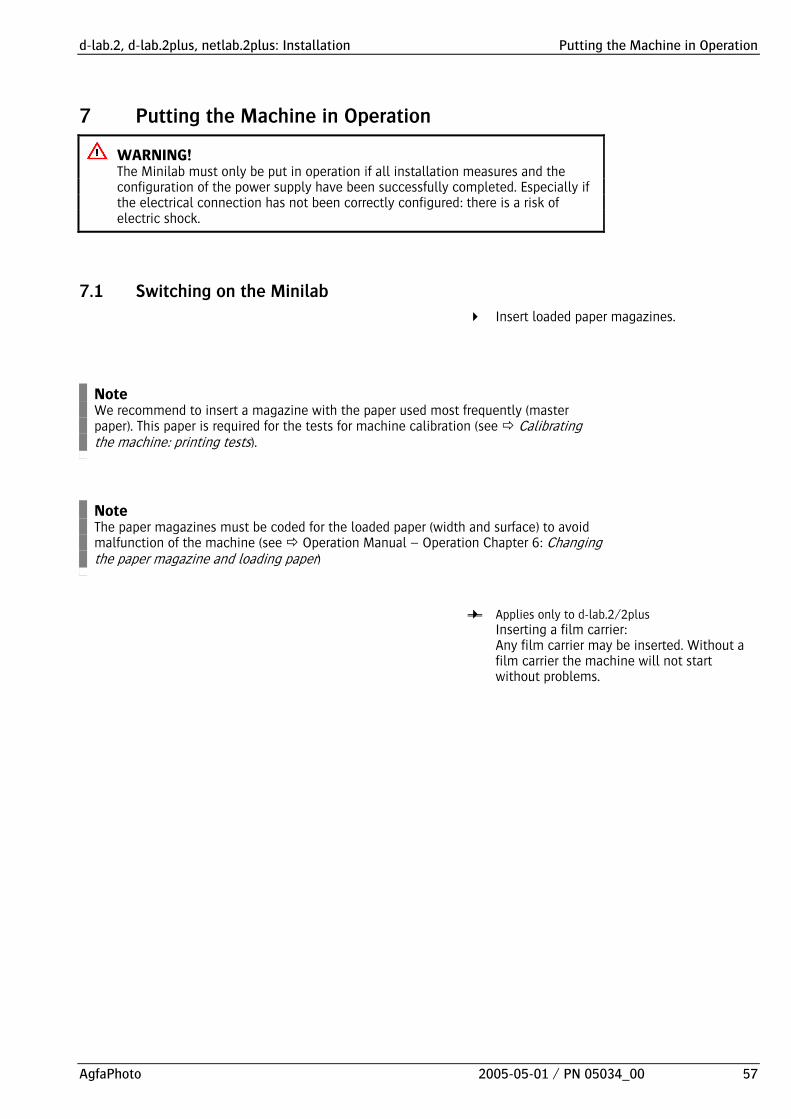
7.1 Switching on the Minilab
Insert loaded paper magazines.
Note We recommend to insert a magazine with the paper used most frequently (master paper). This paper is required for the tests for machine calibration (see Calibrating the machine: printing tests).
Note The paper magazines must be coded for the loaded paper (width and surface) to avoid malfunction of the machine (see Operation Manual – Operation Chapter 6: Changing the paper magazine and loading paper)
Applies only to d-lab.2/2plus Inserting a film carrier: Any film carrier may be inserted. Without a film carrier the machine will not start without problems.

Putting the Machine in Operation d-lab.2, d-lab.2plus, netlab.2plus: Installation
58 2005-05-01 / PN 05034_00 AgfaPhoto
dlab2125
Switch on the ground fault interrupter (GFI switch; 2), if necessary. The GFI switch remains always on.
Switch on the main breaker (1).
The machine starts.
CAUTION! If the Minilab must be switched off again, only use the main breaker in emergencies.
CAUTION! Switching off via the main breaker reduces the life span of the laser and the main computer hard disk considerably (the fan of the lasers is switched off, so the required cooling of the lasers cannot be guaranteed). Paper jam may occur in case of paper in the Printer or in the Paper Processor.
Shutdown:
Press the buttons End of work > Shutdown on the touch-screen.
Only switch off the main breaker if this is required by the operation (e.g. some routines during changing of chemicals; see Operation Manual – Operation, Chapter 3, and Switching the machine on and off in the Operation Manual – Operation, Chapter 2).
Note For the daily routines we recommend to start the machine via timer and switch off via the buttons End of work > Shutdown. Thereby the main breaker remains on (see Switching the machine on and off in the Operation Manual – Operation, Chapter 2).

d-lab.2, d-lab.2plus, netlab.2plus: Installation Putting the Machine in Operation
AgfaPhoto 2005-05-01 / PN 05034_00 59
7.2 Checking the Software of the Paper Processor
Printer and Paper Processor are delivered as individual machines and will only be combined to the Minilab during the installation. Therefore the software installed on the Paper Processor must be checked:
Check “Firmware Version” via ServiceGUI and compare with the information in file “ppsw.cfg” (folder C:\dlab\dlab’version‘\pp\install\ Dlab.2_Vxx; see Service Manual – Repair)
If the ServiceGUI indicates another version than the file, an update must be made as follows:
After the software started up, change immediately to the ServiceGUI:
Select Firmware Download.
Select Paperprozessor - p main software.
Select the file c:\dlab\ dlab.2+3_VXXX\PP\install\ Dlab.2_VYYY\d12.bin and start the download.
Once the download is completed, execute the script: scripts prosser\ dlab2_time_reset.txt
Proceed with the following step of the Installation Instructions (see Entering Correction Values for the Paper Processor Temperatures and Pumps) and check file “dlab_pp.cfg“ in addition and correct if necessary: DWSHT000 BWSHT000 SWSHT000 WRLIM200 DSTYP1
Putting the Machine in Operation d-lab.2, d-lab.2plus, netlab.2plus: Installation
60 2005-05-01 / PN 05034_00 AgfaPhoto
7.3 Entering Correction Values for the Paper Processor Temperatures and Pumps
At the inside of the lower, left hand door of the Paper Processor there is a sticker with the correction values xx for the temperatures and pumps:
DV temperature sensor [DVSNS] xx BF temperature sensor [BFSNS] xx ST temperature sensor [STSNS] xx DW water replenish pump [DWADJ] xx BW water replenish pump [BWADJ] xx SW water replenish pump [SWADJ] xx
They must be checked, and entered again if necessary.
Go to Service, open the folder Config Files and select the dlab_pp.cfg file.
Make sure that the number of digits of the correction value remains the same: If you need to change to value “3”, for example, and the previous value was “01”, enter “03” as the new correction.
The CYCLE value must be set on “0” for 50 Hz operation and on “1” for 60 Hz operation.
After completion of this correction exit the menu with save, load, and import to data base.

d-lab.2, d-lab.2plus, netlab.2plus: Installation Putting the Machine in Operation
AgfaPhoto 2005-05-01 / PN 05034_00 61
7.4 Setting the Replenishment Rates
The replenishment depends on the throughput, i.e. it depends on the actually processed paper per day. When the machine is put in operation for the first time, a starting value must be entered.
Note The replenishment data for the individual solutions DEV (developer), BX (bleach-fix), and STB (stabilizer) cannot be changed separately. If the replenishment rate is changed for one solutions, the other two solutions are automatically changed by the same ratio.
Check the preset replenishment:
Press in this order: Settings Machine settings PP Replenishm.
034
The Replenishment settings screen opens.
If the value for Average throughput in 5 days is lower than “20”, press Activate normal repl. The value entered for Increased repl. (preset value “10”) is used as starting value for the Average throughput in 5 days.
Press OK.
The actual average is calculated and displayed after five days of operation.

Putting the Machine in Operation d-lab.2, d-lab.2plus, netlab.2plus: Installation
62 2005-05-01 / PN 05034_00 AgfaPhoto
7.5 Setting Temperatures and Calibrating Sensors
014
Call up:
Press in this order: Settings Machine settings PP temperature
The screen Paper Processor temperature settings opens.
Check the nominal values and adjust if necessary
Check the values entered in the buttons DEV, BX, STB (developer, bleachfix, stabilizer) and Dryer one after the other, press the buttons, if necessary, and enter the respective nominal temperatures: DEV 40 °C ± 0.3 BX 38 °C ± 3 STB 37 °C ± 3 Dryer 65 °C

d-lab.2, d-lab.2plus, netlab.2plus: Installation Putting the Machine in Operation
AgfaPhoto 2005-05-01 / PN 05034_00 63
Calibrate the temperature sensors
Note The following steps must be carried out for all three solutions (DEV, BX, STB) one after the other!
Press Readjust DEV [Readjust BX / Readjust STB]. A window with a numeric keypad opens. The temperature of the selected solution is indicated in the first line of the dialog field.
Remove the chemical filter of the respective solutions (DEV / BX / STB) as described in Replacing the chemical filters in Chapter 8.
CAUTION! Observe the safety instructions for the handling of chemicals (see Safety instructions in Chapter 3).
Using a calibrated thermometer, measure the current temperature of the processing solution through the free opening of the filter holder.
Enter the measured temperature value via the numeric keypad and press OK: The sensor calibration is executed.
Clean the thermometer.
Proceed with the same routine for the other two solutions.
Resetting the values
In case of incorrect inputs or incorrect calibration of the temperature sensors the default values can be activated:
If necessary press Reset reference and/or Reset calibration.

Putting the Machine in Operation d-lab.2, d-lab.2plus, netlab.2plus: Installation
64 2005-05-01 / PN 05034_00 AgfaPhoto
7.6 Calibrating the Water Pumps
WARNING! Calibrating the water pumps involves a safety risk (electric shock), as it is necessary to work with liquid and the machine is switched on. Therefore we recommend to have the calibration made a service technician.
Note The replenishment pumps are calibrated automatically.
Call up:
Press in this order: Settings Machine settings PP pumps
015
The PP pumps settings screen opens.

d-lab.2, d-lab.2plus, netlab.2plus: Installation Putting the Machine in Operation
AgfaPhoto 2005-05-01 / PN 05034_00 65
Calibrating the pumps
Note The following steps must be carried out for all three pumps (DEV-W, BX-W, STB-W) one after the other!
Special tools – Graduated beaker – Extension hose
Press DEV-W [BX-W / STB-W] and enter the calibration volume (water supply rate, e.g. 100 ml).
Open the cover of the tank section; make sure that the cover engages in vertical position.
G_PP101
Remove the cover in front of the machine tank DEV [BX / STB] (1 screw).
Note There are two hoses below each cover, one for chemicals and one for water. The water hose is always the transparent hose, the hoses for the chemicals are colored (blue, red, or yellow).
Pull out the water hose (incl. elbow).

Putting the Machine in Operation d-lab.2, d-lab.2plus, netlab.2plus: Installation
66 2005-05-01 / PN 05034_00 AgfaPhoto
The hose is very short. Therefore increase the length with a piece of hose of matching diameter.
Hold the end of the hose in a graduated beaker.
015
Press Activate DEV-W pump [Activate BX-W pump / Activate STB-W pump]. The buttons are only active if a supply rate has been entered for this pump. The pump switches on and pumps the set amount of water into the measuring cylinder more or less accurately, always depending on the quality of the present calibration. Then the pump switches off again.
Check the supplied amount of water on the scale of the measuring cylinder.
Press the respective button Readjust DEV-W pump [Readjust BX-W pump / Readjust STB-W pump] and enter the measured supply rate. The calibration of the pump is executed.
Empty the graduated beaker.

d-lab.2, d-lab.2plus, netlab.2plus: Installation Putting the Machine in Operation
AgfaPhoto 2005-05-01 / PN 05034_00 67
Repeat the calibration for the selected pump to check if the calibration is correct:
Hold the end of the hose in a graduated beaker.
Press Activate DEV-W pump [Activate BX-W pump / Activate STB-W pump].
Check the supplied amount of water on the scale of the graduated beaker.
Press the respective button Readjust DEV-W pump [Readjust BX-W pump / Readjust STB-W pump] and enter the measured supply rate.
Empty the graduated beaker.
Repeat the procedure if the calibration is not correct. If it is correct proceed as described below.
Remove the extension hose and connect the water hose again.
Proceed with the same routine for the other two pumps.
Mount the tank covers again (1 screw each).
Close the tank section cover:
Support the cover with one hand.
Press (PUSH) to unlock the cover.
Close the cover.
Resetting the calibration
In case of incorrect calibration the pumps can be reset to default:
Press the button Reset to standard.

Putting the Machine in Operation d-lab.2, d-lab.2plus, netlab.2plus: Installation
68 2005-05-01 / PN 05034_00 AgfaPhoto
7.7 Brief Information for Operators during Warm-Up
While the machine is heating up, the operator can be informed of the fundamentals of the operation and maintenance, as well as of errors, which can be removed by the operator.
This brief information should only serve as refreshment of a previous operating training and cannot replace proper training!
7.8 Checking the Process
The quality of the chemical solutions is checked by means of the chemical control strip test. For this test the preexposed chemical control strip is inserted in the machine, processed, and then analyzed. The evaluation of the chemical control strips shows if the chemicals are OK or not. If they are not OK, they must be replaced.
Order number of the digital chemical control strips( 5x5): (ABC code) 5HWGX
The following requirements must be met:
– the machine must be ready for operation (working temperature reached),
– and there is no order in process.
G_SD701
Open the Printer front door: The control strip box is located in the lower part of the Lane Distributor, LD (d-lab.2) resp. Sheet Distributor, SD (d-lab.2plus, netlab.2plus).
Open the lock of the control strip box and remove the box.

d-lab.2, d-lab.2plus, netlab.2plus: Installation Putting the Machine in Operation
AgfaPhoto 2005-05-01 / PN 05034_00 69
1 2
23
dlab2608
1 Control strip box
2 Emulsion side / photographic layer
3 Notch
In a darkroom insert the control strip into the control strip box, with the notch on the bottom right hand side (smooth side – emulsion side – facing down; see illustration). If the test strip was accidentally inserted the wrong way round, the developed strip shows obvious dirt marks (emulsion side up) or the preexposed measuring fields were fogged and cannot be analyzed.
dlab2195
Press in this order: Test Control strip Chemical control strip Then a prompt pops up to insert the chemical control strip.
Insert the control strip box in the provided holder in the Lane Distributor, LD (d-lab.2) resp. Sheet Distributor, SD (d-lab.2plus, netlab.2plus).
Close the Printer front door and press Continue: The control strip is transported into the Paper Processor and processed there. A message indicates when the box should be removed.
Remove the box or leave it in the machine until the next test.
Remove the developed chemical control strip and analyze it.
A first evaluation is possible by comparing the developed control strip with the reference strip enclosed in the box (place both strips side by side and compare them in daylight conditions). Use a densitometer for a more detailed evaluation.
If the densities in the measuring fields correspond to the nominal values the production can be started. If not, the chemicals must be replaced (see Chapter 3).

Preparing the Machine for Production d-lab.2, d-lab.2plus, netlab.2plus: Installation
70 2005-05-01 / PN 05034_00 AgfaPhoto
8 Preparing the Machine for Production Before you are able to start production, various settings must be entered and tests must be made.
8.1 Entering the Settings
Many settings have standard values which are preset prior to delivery. These standard values usually allow at least a test operation of the machine. For the normal machine operation they must then be adapted to the requirements of the laboratory or the operator(s).
All settings are explained in detail in the Operation Manual – Operation.
However, to avoid problems we recommend to proceed as follows even before a test operation:
Check the paper settings and change if necessary (see Operation Manual – Operation, Chapter 4: Defining paper width, surfaces and cut lengths).
Adjust the paper magazine(s) to the paper width(s) in use and set the code according to the settings on the machine (if this has not been done before putting the machine in operation; see Operation Manual – Operation, Chapter 6: Changing the paper magazine and loading paper)
Create sub-configurations (paper, back print, correction, indexprint, etc.) and combine them to form order configurations (see Operation Manual – Operation, Chapter 4: Creating and editing print configurations and Defining and editing order configurations).

d-lab.2, d-lab.2plus, netlab.2plus: Installation Preparing the Machine for Production
AgfaPhoto 2005-05-01 / PN 05034_00 71
8.2 Calibrating the Machine and Running Tests
The machine must be calibrated to produce optimum print results. The calibration excludes color casts, incorrect exposure and/or blooming effects.
Setting the master paper (master paper: the most commonly used paper; see Operation Manual – Operation, Chapter 4: Machine settings / Further settings).
Print a PBL with laser point on MBL paper.
Print an MBL
Exact procedure (see Operation Manual – Operation Chapter 5).
Print a test print: Press in this order: Service Scripts Scripts for Service Test prints x-print.txt Enter the serial number (FN) of the machine in the pop-up window. Print to ensure that the machine works. If there are any problems with the paper transport (paper running askew, paper jam) proceed as follows: Problem occurs only a few hours after installation / removal of transport protections: Repeat the paper transport approximately 24 hours after the transport protections have been removed.
The problem occurs approx. 24 hours after the transport protections have been removed: Check the height adjustment of the print engine and adjust if necessary (see Repair Instructions).
Reason: The rubber suspension of the print machine only reaches the final position after this time (relieve of tension, temperature effects).

Installation report d-lab.2, d-lab.2plus, netlab.2plus: Installation
72 2005-05-01 / PN 05034_00 AgfaPhoto
9 Installation report Fill in the installation report completely and fax it to the indicated address.
Use the return envelope to send the test prints (1 PBL, 1 MBL, 1 test print) to AgfaPhoto-Gera.

d-lab.2, d-lab.2plus, netlab.2plus: Installation Index
AgfaPhoto 2005-05-01 / PN 05034_00 73
10 Index
A Additional work table 32
Adjust
temperatures 62
Adjusting feet, mounting 9
B Back printer, inserting the ink ribbon
d-lab.2 41
d-lab.2plus/netlab.2plus 42
C Calibrate
Machine 71
Calibration
temperature sensors 63
water pumps 64
Central water tank, first filling 52
Chemicals
mixing 48
testing 68
Conventions
pictographs 3
text styles 3
Correction values Paper Processor, entering 60
D Deposit for large prints 36
Drive Bay, connecting 40
Dryer
check / adjust voltage 47
E Easy Paper Box 55
F Film brush, mounting 35
Film Takeup, mounting 35
I Ink ribbon back printer
d-lab.2 41
d-lab.2plus/netlab.2plus 42
Inserting chemical filters 54
Installation
tools 18
Installation report 72
M Machine
putting in operation 57
Main computer, removing panels 21
Mains frequency, 50Hz / 60Hz 46
Mixing replenisher chemicals
with the d-lab.2 Easy Paper Box 55
Monitor, connecting 38
O Operation Manual
available documentation 1
guideline 2
Machines 1
Operation start 57
P Paper Processor
entering correction values 60
installing on site 18
software check 59
temperatures check / adjust 62
testing chemicals 68
weight 4
Pictographs 3
Power supply 43
Printer
connecting to Paper Processor 26

Index d-lab.2, d-lab.2plus, netlab.2plus: Installation
74 2005-05-01 / PN 05034_00 AgfaPhoto
weight 4
Process check 68
Production, preparing the machine 70
R Removing panels
main computer 21
scanner 21
Replenishment rates, setup 61
S Safety instructions
handling of chemicals 48
Scanner, removing panels 21
Screen, connecting 38
Service Manual
Available documentation 1
Guideline 2
Setup
replenishment rates 61
Software check Paper Processor 59
Sorter 35
Stands, mounting 9
T Table top 32
Temperature sensors, calibrating 63
Temperatures, check and adjust 62
Text styles 3
Transport 4
packed 5
unpacked 6
vertical 4
Transport protections
Print Engine, PE (d-lab.2 20
Print Machine, PM (d-lab.2plus/netlab.2plus) 20
scanner 24
transport section / feeder unit (FU) 25
V Vertical transport 4
W Water tank, first filling 52
Weight 4
Z Zoom lens, mounting 37


