D F D C S FPGA PLATFORM - Aircc Digital Libraryaircconline.com/vlsics/V4N1/4113vlsics05.pdf · ·...
10
International Journal of VLSI design & Communication Systems (VLSICS) Vol.4, No.1, February 2013 DOI : 10.5121/vlsic.2013.4105 51 DUAL FIELD DUAL CORE SECURE CRYPTOPROCESSOR ON FPGA PLATFORM C Veeraraghavan 1 and K Rajendran 2 1 Department of Electronics and communication, Sri Krishna Arts and Science College, Coimbatore,Tamilnadu, India [email protected] 2 Department of Electronics, Government Arts College for women, Ramanathapuram, Tamilnadu, India [email protected] ABSTRACT This paper is devoted to the design of dual core crypto processor for executing both Prime field and binary field instructions. The proposed design is specifically optimized for Field programmable gate array (FPGA) platform. Combination of two different field (prime field GF(p) and Binary field GF(2 m )) instructions execution is analysed.The design is implemented in Spartan 3E and virtex5. Both the performance results are compared. The implementation result shows the execution of parallelism using dual field instructions KEYWORDS Crypto processor, FPGA, Prime field, Binary field. 1. INTRODUCTION The term cryptography represents the encryption of data. For the secured data communication cryptography is essential one. With rapid increases in communication and network applications, cryptography has become a crucial issue to ensure the security of transmitted data. Cryptography is used now a days in a variety of different applications. Every application has its own design criteria and raises special requirements for hardware designs. While contactless powered devices have to meet low-power constraints, battery-powered devices need energy-aware implementations that consume as little energy as possible to increase the life-time of the battery. The most fundamental decision concerning future hardware designs is whether to use a binary- extension field or a prime field as basis of the used crypto processor. A secure crypto processor is a dedicated microprocessor chip for carrying out cryptographic operation. For increasing the speed of execution this paper is designing the dual core crypto processor. At the same time for decreasing the power consumption this design is implemented in the FPGA.
Transcript of D F D C S FPGA PLATFORM - Aircc Digital Libraryaircconline.com/vlsics/V4N1/4113vlsics05.pdf · ·...

International Journal of VLSI design & Communication Systems (VLSICS) Vol.4, No.1, February 2013
DOI : 10.5121/vlsic.2013.4105 51
DUAL FIELD DUAL CORE SECURE
CRYPTOPROCESSOR ON FPGA PLATFORM
C Veeraraghavan1 and K Rajendran
2
1Department of Electronics and communication,
Sri Krishna Arts and Science College, Coimbatore,Tamilnadu, India [email protected]
2Department of Electronics,
Government Arts College for women, Ramanathapuram, Tamilnadu, India [email protected]
ABSTRACT
This paper is devoted to the design of dual core crypto processor for executing both Prime field and binary
field instructions. The proposed design is specifically optimized for Field programmable gate array
(FPGA) platform. Combination of two different field (prime field GF(p) and Binary field GF(2m))
instructions execution is analysed.The design is implemented in Spartan 3E and virtex5. Both the
performance results are compared. The implementation result shows the execution of parallelism using
dual field instructions
KEYWORDS
Crypto processor, FPGA, Prime field, Binary field.
1. INTRODUCTION
The term cryptography represents the encryption of data. For the secured data communication
cryptography is essential one. With rapid increases in communication and network applications,
cryptography has become a crucial issue to ensure the security of transmitted data. Cryptography
is used now a days in a variety of different applications. Every application has its own design
criteria and raises special requirements for hardware designs. While contactless powered
devices have to meet low-power constraints, battery-powered devices need energy-aware
implementations that consume as little energy as possible to increase the life-time of the battery.
The most fundamental decision concerning future hardware designs is whether to use a binary-
extension field or a prime field as basis of the used crypto processor.
A secure crypto processor is a dedicated microprocessor chip for carrying out cryptographic
operation. For increasing the speed of execution this paper is designing the dual core crypto
processor. At the same time for decreasing the power consumption this design is implemented in
the FPGA.

International Journal of VLSI design & Communication Systems (VLSICS) Vol.4, No.1, February 2013
52
This paper is concentrate to design a dual crypto processor used to execute both prime and binary
field instructions.
2. RELATED WORK
Only a few papers companied binary and prime fields in hardware. Dual field arithmetic unit for
GF(p) and GF(2m) is designed by Johannes Wolkerstorfer[3]. This paper design the
multiplication, squaring, addition, subtraction and inversion in both fields GF(p) and GF(2m)).
J. Goodman et al. presented in [13] a VLSI implementation of a dual-field arithmetic unit. Their
so-called Domain-Specific Reconfigurable Cryptographic Processor (DSRCP) is not a mere
multiplier for GF(p) and GF(2m GF(2m). It can calculate all operations required for elliptic curve
cryptography including inversion and comparisons. These operations are executed on an
extensive datapath which is controlled by a microcoded control unit. Main components of the
datapath are a carry-propagate adder for operation in GF(p) that takes three cycles for an addition
and a reconfigurable datapath for operation in GF(2m). An additional comparator allows
comparisons of integers or polynomials. The Montgomery algorithm is used for multiplication in
GF(p). Multiplication in GF(2m) obeys an iterative MSB-first scheme with interleaved modular
reduction.
3. IMPLEMENTING PRIME FIELD AND BINARY FIELD IN FPGA. In 1983, Blakley introduced an algorithm to perform Modular multiplication of two integers A
and B modulo an integer M[4]. It is an iterative binary double-and-add algorithm. The main idea
of the algorithm is that it keeps the intermediate result after each iteration below the modulus
value, which it avoids final division. In this paper, the modulus M corresponds to p and we say it
Fp multiplication. All arithmetic in Fp are performed in two’s complement number system, which
avoids input and output conversions like existing implementations [11], [12].
3.1. Fast Carry Chains for Fp –Primitives
The main difficulty of the Blakley algorithm is the computation of addition on large operands.
The modified Blakley algorithm for large operands is shown in [5] and [6]. The use of carry save
adder (CSA) helps to speed up the repeated additions on large operands. However these modified
versions require at least one final addition on large carry chain. Some pre-computed values too
are used by this technique which requires additional time and storage area.
This work exploits the features available in an FPGA device for efficient computation of Blakley
algorithm on large operands. The specific features that are available in an FPGA device are
efficiently utilized for developing arithmetic primitives in F2m fields in [7]. However, this paper
looks after the same for Fp. The modern FPGA consists of 16 slices (or 32 LUTs) within a single
row which is connected through an in-built fast carry chain (FCC). The FCC can perform addition
on two 32-bit operands most efficiently compared to any other adder.Structures [8] . It is
experimentally shown that on a Virtex-4 FPGA device the latency of a 32-bit addition using a fast
carry chain takes only 5.8 ns, whereas the same using a carry look ahead structure takes 8.7 ns.
Hence, fast carry chain is 1.5 times faster than carry look ahead structure for computing addition

International Journal of VLSI design & Communication Systems (VLSICS) Vol.4, No.1, February 2013
53
of two 32-bit operands on an FPGA platform. In order to compute an addition of two operands
longer than 32 bits, the FPGA will utilize more than one row which requires additional routing
delay. For example, the addition (A+B) of two 64-bit operands (A, B) using a single 64-bit carry
chain is slower than the same using three 32-bit FCC and a 2:1 multiplexer [8].
We develop an efficient 256-bit adder useful to Fp256–arithmetic using 32-bit fast carry chains.
The repeated Karatsuba decomposition is applied on 256-bit operands. An operand is
decomposed up to a depth of three for converting it into eight pieces of 32-bit operands. A 64-bit
addition is performed by using three 32-bit fast carry chains with a carry select structure.
Let, A = A1232
+ A0, B1232
+ B0 and C=A+B, where Ai, Bi are 32-bit integers. We compute A0 + B0,
A1 + B1 +0,and A1 + B1 +1 in parallel on three FCC. Then the carry out of the least significant
addition (A0 + B0) is used to multiplex the results of the most significant additions. Thus the
latency of a 64-bit adder is 1 FCC + 1 MUX, where MUX corresponds to a 2:1 multiplexer.
Similarly, a 128-bit adder is developed by three 64-bit adders, and a 256-bit adder is developed
by three 128-bit adders. Therefore, a 256-bit adder is developed from 32 bit adders.
Fig1. Architecture of Fp adder/subtractor/multiplier unit

International Journal of VLSI design & Communication Systems (VLSICS) Vol.4, No.1, February 2013
54
Fig. 2. Internal Structure of a 256 bit adder
3.2. Architecture Description for prime field
Our first objective for designing such an integrated architecture is to reduce the overall hardware
costs for computing three essential prime field operations in pairing computation. The
architecture consists of several independent blocks which operate in parallel for accelerating the
execution of respective operations. The whole architecture is subdivided into four macro-
blocks(A1,A2,A3,A4) and seven micro-blocks (B1,B2,B3,B4,B5,B6,B7). The macro-blocks are
used to compute the arithmetic operations, whereas, micro-blocks are primarily responsible for
dataflow among the macro-blocks, the registers, and the I/O ports. The functionality of the
individual blocks are described here.
• Macro-blocks A1,A2& A4 are 256-bit adders based on our proposed technique is shown
in Fig1.
• Block A3 performs 2µ for an integer µ£Fp . This is done by simply one bit left shift
having only rewiring and no additional logic cells.
• Micro-block B1 consists of one 2:1multiplexer that selects either v1 or w1 based on the
most significant bits (or carry outs) of 2µ and 2µ -p operations. Therefore, this block
completes the 2µ mod p operation.
• Block B2 selects either s1 or s2 as the input to the A3.
• Blocks B3,B4 and B5 help to compute Fp —addition and subtraction in A1 and A2. The
control signal c0 holds zero for addition and one for subtraction. Thus, if c0 =1 then
block B5 selects -s2 else it selects s2 . Similarly, if c0 =1 then block B4 selects p else it
selects -p. Block B3 completes the operation by selecting the correct result. In case of Fp -
subtraction (i.e., c0 =1), it selects either v2 or w2 based on the most significant bit (MSB)
of only, whereas, for Fp -addition it does the same based on the MSB of both v2 and w2.
• Blocks B6 and B7 multiplex t1 (the output of 2µ mod p) and t2 (the output of s1±s2 mod
p ) as the new value of s1 and s2 and registers, respectively.
At every level of hierarchy it adds one
additional MUX in the critical path. Thus
the latency of a 256-bit adder is 1 FCC + 3
MUX delay, which is 9.9 ns on a Virtex-4
FPGA, whereas the latency of a 256-bit
carry look ahead adder on the same
platform is 16.7 ns, which is 1.7 times
slower than the above technique. we
develop a programmable Fp-primitive
based on above 256-bit high-speed adder
circuits. Prime field operations carry over
are addition, subtraction, and
multiplication. Fig. 1 depicts the overall
resulting architecture of the proposed Fp -
adder/subtractor/multiplier unit, where the
internal dataflow of A256 blocks are shown
in Fig. 2.

International Journal of VLSI design & Communication Systems (VLSICS) Vol.4, No.1, February 2013
55
3.3 Binary field execution unit for addition
Fig.3. Binary Field Addition Unit Block Diagram
The binary field addition is designed by using the XOR gate operation.
4. INSTRUCTIONS IMPLEMENTATION FOR PRIME FIELD AND
BINARY FIELD
4.1.Instruction 1- Computation of Fp Multiplication
Proposed Fp –primitive follows the parallelism technique of Montgomery ladder [2] for
computing Blakley multiplication algorithm in Fp [4].
Basic Blakley technique for computing c=ab mod p with input parameters a and b is as follows
c←0
For i from 0 to k-1 do
c←2c+a.bk-1-i
c←c mod p
return c.
The choice of this algorithm is due to its lower hardware cost and intrinsic adaptability to
Montgomery ladder for parallelism. We rewrite it, in Algorithm 2 with parenthesized indices in
superscript in order to emphasize the intrinsic dependency as well as parallelism of the
multiplication procedure.
Algorithm 1: The interleaved multiplication based on Montgomery ladder.
Input: p, a= ∑ 2� ����� and
, b= ∑ 2� ���
�� .
Output:a.b. mod p
1. s1(n)
←0; ← (n)
←a
2. For i=n - 1 down to 0 do
3. if bi=1 then u(i)
←s2(i+1)
; else u(i)
← s1 (i+1)
;
4. υ1 (i)
← 2υ (i)
5. υ2 (i)
←s1(i+1)
+s2 (i+1)
;
6. ω1 (i)
←υ1(i)
+(p¬)+1;
7. ω2 (i)
←υ2(i)
+(p¬)+1;;
8.c1 (i)
←(υ1(2)
) n (ω1(i)
) n ;
9. c2 (i)
←(υ2(2)
) n (ω2(i)
) n ;
10. if c1 (i)
=1 then t1 (i)
← ω1
(i); else t1
(i) ←
υ1 (i)
;
11 .if c2 (i)
=1 then t2 (i)
← ω2
(i); else t2
(i) ←
υ2 (i)
;

International Journal of VLSI design & Communication Systems (VLSICS) Vol.4, No.1, February 2013
56
12.if b1 (i)
=1 then s1 (i)
← t 1
(i); else s1
(i) ←
t1
(i);
13.if b2 (i)
=1 then s2 (i)
←t 2
(i); else s2
(i) ←
t2
(i);
14. end for
15. return s1 (0)
;
[In this algorithm,x(i)
represents the value of x at ith iteration,(x)n indicates the nth bit of x , and
indicates logical OR.]
The algorithm computes two intermediate results (s1 (i)
and s2 (i)
) in each iteration. The data
transfer inside the architecture (see Fig. 1) for computing (a.b) mod p is as follows.
• The register s1 and s2
hold the iterative results s1
(i)and s2
(i)of Algorithm 2, which are
initialized by zero and a, respectively, as specified in step 1.
• Iterative execution starts from i = n – 1 and goes down to zero as shown in step 2. This
step is executed by a 8-bit counter, which belongs to the control part of the proposed
design and it is not shown in Fig. 1.
• Block B2 of Fig. 1 executes step 3. The modular doubling (as computed by executing the
steps 4, 6, 8, and 10) and the modular addition (as computed by executing the steps 5, 7,
9, and 11) are performed in parallel. In Fig. 1, steps 4 and 6 are performed in blocks A3
and A4, respectively, whereas, both the steps 8 and 10 are performed in block B1.
Similarly, steps 5 and 7 are performed in blocks A1 and A2, respectively, whereas, both
the steps 9 and 11 are performed in block B3. During the execution of Fp -multiplication
Control signal c0 remains zero.
• Finally, results of the current iteration are restored as specified in step 12 and step 13 in
parallel B6 and B7 blocks. All steps from step 3 to step 13 of Algorithm 2 are performed
within one clock by the proposed architecture. Therefore, to compute a multiplication in
Fp256 the proposed design takes only 256 clock cycles.
4.2. Instruction 2- Computation of Fp Addition
The proposed design executes Algorithm 2 for computing Fp -addition. As described in step 1,
the architecture initializes registers s1 and s2 by operands and , respectively. It executes steps 2
and 3 in blocks A1 and A2 . Based on the most significant bits of υ2 and ω2 it produces the
correct s1+ s2 result of mod p in block B3 as described in Step 3 and step 4. During the execution of
Fp -addition the control signal c0 holds logic zero. The proposed architecture computes a Fp -
addition in one clock cycle.
Algorithm 2: The addition in prime field.
Input p,a= ∑ 2� ����� and
b= ∑ 2� ���
�� .
Output a+b mod p .
1. s1 ←a; s2 ←a;
2. υ2 ←s1 + s2
3. ω2 ←υ1 +(p¬)+1 ;
4 c2 ←(υ2) n (ω2 ) n;
5. If c2 =1 then t2
←
ω2 ; else t2
←
υ2 ;
6. Return t2;

International Journal of VLSI design & Communication Systems (VLSICS) Vol.4, No.1, February 2013
57
4.3. Instruction 3- Computation of Fp Subtraction
Subtraction a-b mod p.on the proposed design is performed by executing Algorithm 3.It is
executed by the architecture mostly like Algorithm 2 with additional help by block B5 for -S2.
Algorithm 3: The subtraction in prime field.
Input p,a= ∑ 2� ����� and
b= ∑ 2� ���
�� .
Output a-b mod p .
1. s1 ←a; s2 ←a;
2. υ2 ←s1 + (¬s2)+1;
3. ω2 ←υ1 + p;
4 c2 ←(υ2) n ;
5. if c2 =1 then t2
←
ω2 ; else t2
←
υ2 ;
6. Return t2;
4.4. Instruction 4- Computation of Binary addition
Addition of a and b in binary field is performed by the exclusive OR gate.
Result = a XOR b.
5. EXECUTION OF PARALLEL INSTRUCTIONS
The Fig4 shows the dual core structure execution unit block diagram. The mechanism and
regularity of data access for computing all instructions are fairly simple. The distribution of
access to the registers and resolution of access conflicts are handled efficiently at the runtime by a
dedicated hardware block called data access unit which communicates among the CAUs and the
registers.. The DAU takes care of granting accesses. Therefore, a simple multiplexing protocol is
used between CAUs and registers, which is able to confirm a request within the same cycle in
order not to cause any delay cycles when trying to access data in parallel. The data accesses and
instruction sequences are hard coded into the sequence control of the architecture which avoids
the additional software development costs. The dependencies of the instructions are predefined
and thus the access conflicts are known. The priority of the data processing and the respective
execution is rearranged accordingly which achieves maximum utilization of CAUs.
Fig.4. Dual Core Structure Block Diagram

International Journal of VLSI design & Communication Systems (VLSICS) Vol.4, No.1, February 2013
58
Fig.5. I/O Representation Diagram
The data access unit or DAU acts as a mediator while transferring data between CAUs and
memory elements. Due to the demand of parallel access, the proposed crypto processor stores all
intermediate results in its active registers. Each of the register consists of data-in, data-out, and
enables lines. It gets updated by data-in lines when the respective enable signal is invoked. The
crossbar switch (results) redirects the outputs of each operation to registers. Similarly, the
operands are redirected from registers to the input ports of the CAUs. The respective select
signals are generated prior to the above two redirection procedures by the sequence control unit.
The access control block synchronizes the select lines of the multiplexers for operands and
results. It also synchronizes the enable signals of registers for restoring the intermediate results.
The micro instruction sequence generator finds the current operation type and generates the
respective micro instructions which are nothing but the control signals. The respective values of
control signals, which on the other hand, represents the scheduling of different operations on
CAU.
Fig.6. Prime Field Addition and Binary Field Addition parallel execution waveform
International Journal of VLSI design & Communication Systems (VLSICS) Vol.4, No.1, February 2013
59
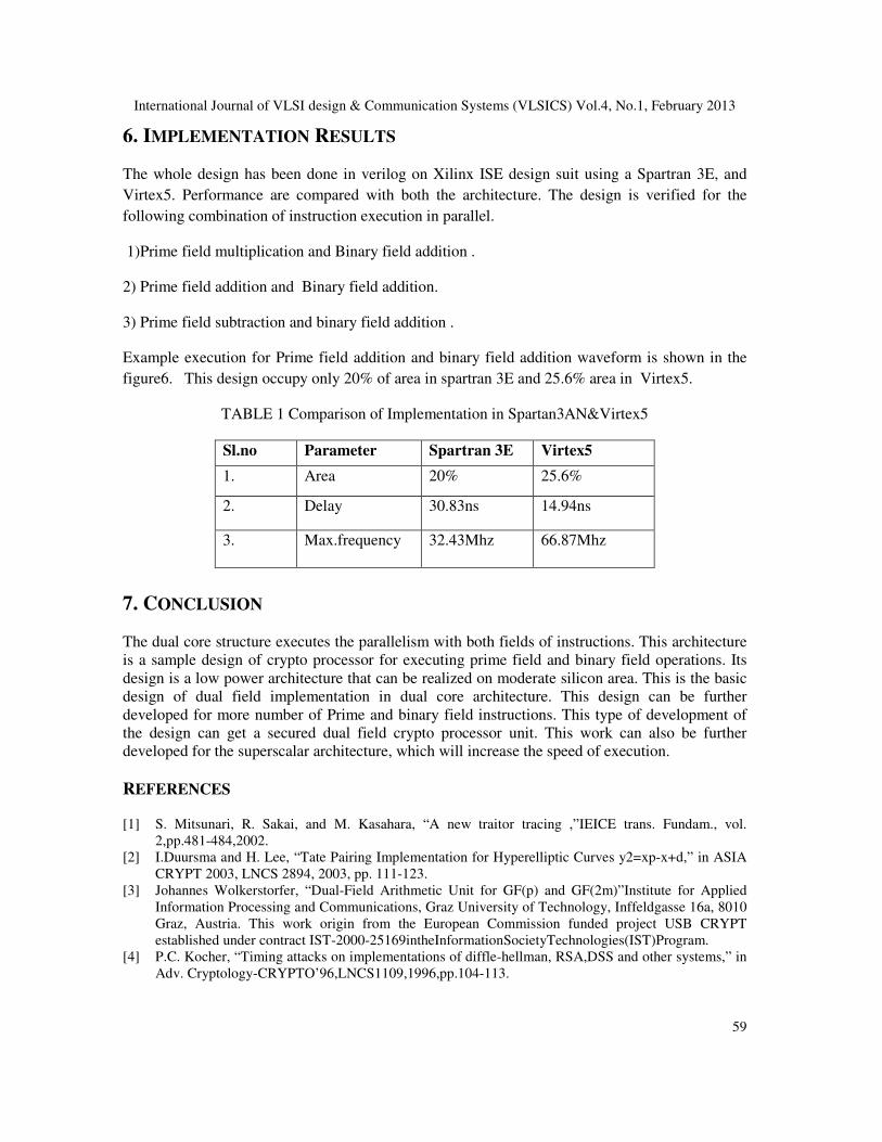
6. IMPLEMENTATION RESULTS
The whole design has been done in verilog on Xilinx ISE design suit using a Spartran 3E, and
Virtex5. Performance are compared with both the architecture. The design is verified for the
following combination of instruction execution in parallel.
1)Prime field multiplication and Binary field addition .
2) Prime field addition and Binary field addition.
3) Prime field subtraction and binary field addition .
Example execution for Prime field addition and binary field addition waveform is shown in the
figure6. This design occupy only 20% of area in spartran 3E and 25.6% area in Virtex5.
TABLE 1 Comparison of Implementation in Spartan3AN&Virtex5
Sl.no Parameter Spartran 3E Virtex5
1. Area 20% 25.6%
2. Delay 30.83ns 14.94ns
3. Max.frequency 32.43Mhz 66.87Mhz
7. CONCLUSION
The dual core structure executes the parallelism with both fields of instructions. This architecture
is a sample design of crypto processor for executing prime field and binary field operations. Its
design is a low power architecture that can be realized on moderate silicon area. This is the basic
design of dual field implementation in dual core architecture. This design can be further
developed for more number of Prime and binary field instructions. This type of development of
the design can get a secured dual field crypto processor unit. This work can also be further
developed for the superscalar architecture, which will increase the speed of execution.
REFERENCES
[1] S. Mitsunari, R. Sakai, and M. Kasahara, “A new traitor tracing ,”IEICE trans. Fundam., vol.
2,pp.481-484,2002.
[2] I.Duursma and H. Lee, “Tate Pairing Implementation for Hyperelliptic Curves y2=xp-x+d,” in ASIA
CRYPT 2003, LNCS 2894, 2003, pp. 111-123.
[3] Johannes Wolkerstorfer, “Dual-Field Arithmetic Unit for GF(p) and GF(2m)”Institute for Applied
Information Processing and Communications, Graz University of Technology, Inffeldgasse 16a, 8010
Graz, Austria. This work origin from the European Commission funded project USB CRYPT
established under contract IST-2000-25169intheInformationSocietyTechnologies(IST)Program.
[4] P.C. Kocher, “Timing attacks on implementations of diffle-hellman, RSA,DSS and other systems,” in
Adv. Cryptology-CRYPTO’96,LNCS1109,1996,pp.104-113.

International Journal of VLSI design & Communication Systems (VLSICS) Vol.4, No.1, February 2013
60
[5] D. N. Amanor, C. Paar, J. Pelzl, V. Bunimov, and M. Schimmler, “Efficient hardware architectures
for modular multiplication on FPGAs,” in proc.Int. Conf. Field Program. LogicAppl.2005,pp.539-
542.
[6] V. Bunimov and M. Schmiller, “Area and time efficient modular multiplication of large integers,” in
Proc. ASAP, 2003,pp.400-409.
[7] C. Reberio and D. Mukhopadhyay,”High speed compact elliptic curve crypto processor for FPGA
platforms,” Indocrypt’08, LNCS5365, pp.376-388, 2008.
[8] S.Ghosh, D. Mukhopadhyay, and D.Roychowdhury,”High speed Fp multipliers and adders on FPGA
platform,” presented at the DASIP’10, Scotland,U.K.,2010.
[9] Santosh Ghosh, Debdeep Mukhopadhyay, and Dipanwita Roychowdhury,” Secure Dual- core Crypto
processor for Curves on FPGA Platform”. DigitalObjectIdentifier 0.1109/TVLSI.2012.2188655.
[10] Jun-Hong Chen, Ming-Der Shieh, Member, IEEE, and Wen-Ching Lin,” A High-Performance
Unified-Field Reconfigurable Cryptographic Processor”. Digital Object Identifier
10.1109/TVLSI.2009.2020397.
[11] D.Kammler, D.Zhang, P.Schwabe,H. charwaechter, M. Langenberg, D. Auras, G. Ascheid, and R.
Mathar, “Designing an ASIP for cryptographic pairings over Barreto-Naehrig Curves,” CHES’09,
LNCS 5747, pp. 254-271,2009.
[12] J. Fan, F. Vercauteren, and I.Verbauwhede,”Faster Fp-arithematic for Cryptographic pairings on
Barreto-Naehrig curves,” CHES’09, LNCS 5747, pp.240-253, 2009.
[13] J. Goodman, A. P. Chandrakasan, An Energy-efficient Reconfigurable Public-Key Cryptography
Processor, IEEE Journal of Solid-State Circuits, pp. 1808–1820, November 2001.
Authors
C.Veeraraghavan received the M.Sc. in Applied Electronics from the Bharathiar
University in the year 1998 and M.Phil. in Electronics with specialization of VLSI
Design from Bharathiar University in the year 2006. Currently, he is pursuing Ph.D at
Sri Krishna Arts and Science college, Department of Electronics and communication
systems, Bharathiar University, Tamilnadu, India.
Dr. K.Rajendran received the Ph.D degree in Electronics from Bharathiar University,
Coimbatore in March 2009. He is currently an Assistant Professor in the Department
of Electronics, Government Arts College for women, Ramanathapuram, Tamilnadu,
India.