Cyclic and Isothermal Oxidation Resistance of ASPS Thermal ...
148
i Cyclic and Isothermal Oxidation Resistance of ASPS Thermal Barrier Coating Systems by Xiaolong Li A thesis submitted to the Faculty of Graduate and Postdoctoral Affairs in partial fulfillment of the requirements for the degree of Master of Applied Science in Mechanical Engineering Carleton University Ottawa, Ontario © 2014 Xiaolong Li
Transcript of Cyclic and Isothermal Oxidation Resistance of ASPS Thermal ...

i
Cyclic and Isothermal Oxidation Resistance of ASPS Thermal Barrier Coating Systems
by
Xiaolong Li
A thesis submitted to the Faculty of Graduate and Postdoctoral Affairs in partial fulfillment of the requirements for the degree of
Master of Applied Science
in
Mechanical Engineering
Carleton University Ottawa, Ontario
© 2014
Xiaolong Li

ii
Cyclic and Isothermal Oxidation Resistance of ASPS Thermal Barrier
Coating Systems
by
Xiaolong Li
A thesis submitted to the Faculty of Graduate and Postdoctoral Affairs in
partial fulfillment of the requirements for the degree of
Master of Applied Science
in
Mechanical Engineering
Professor Xiao Huang, Thesis Supervisor
Dr. Qi Yang, Thesis Co-Supervisor
Professor Metin I. Yaras, Chair, Department of Mechanical and Aerospace
Engineering

iii
Abstract
To systematically study the oxidation performances of thermal barrier coatings (TBCs)
deposited by axial suspension plasma spraying (ASPS) method, isothermal and cyclic
oxidation tests were conducted at a peak temperature of 1080C. The TBC systems are
based on two different nickel-base superalloy substrates (CMSX-4 or IN738LC),
platinum aluminide bond coat and yttria stabilized zirconia (8YSZ) top coat with either
vertical cracks (VC) or columnar structure. After the oxidation tests, the samples were
analyzed using a scanning electron microscope (SEM) and an X-Ray diffractometer.
Samples with IN738LC substrate demonstrated longer isothermal oxidation lives whereas
samples with CMSX-4 substrate showed greater cyclic oxidation lives. Outward
elemental diffusion (of W and Ta) in TBC system containing CMSX-4 contributed to
reduced isothermal oxidation life while the mismatch of coefficients of thermal
expansion (CTE) between TGO, bond coat and substrate was believed to be responsible
for early failure of TBC system with IN738LC substrate. TBC systems with columnar
YSZ overall had longer isothermal oxidation life while vertically cracked YSZ seemed to
result in longer cyclic life. Cr2O3 and spinels (CS), in addition to thermally grown
aluminum oxide (TGO), were detected on tested TBC samples. The growth of spinels
highly depended upon a coating’s accessibility to oxygen and test duration and was found
to contribute the spallation of the coating layer.

iv
Acknowledgements
I would like to thank my supervisor Prof. Xiao Huang for her great guidance
throughout this research program; and I give thanks to my co-supervisor Dr, Qi
Yang for his valuable advices towards experiments and countless time he spent
helping me with EDS and XRD analysis.
To Ms. Olga Lupandina, for generously providing her experimental advice
throughout long period of experimental procedure.
I want to thank the National Research Council of Canada for allowing us the
access to the equipment needed for this research.
I am very grateful to Mrs. F. Lingnau at Chromalloy American Corporation for
providing PtAl coating.
This research could not have been accomplished without the financial support
from Natural Science and Engineering Research Council of Canada. I also want to
express my gratitude to my mother Ms. Yanzhe Sun for always supporting me
financially and spiritually throughout the graduate study.

v
Table of Contents
Abstract .............................................................................................................................. iii
Acknowledgements ............................................................................................................ iv
Table of Contents ................................................................................................................ v
List of Tables .................................................................................................................... vii
List of Illustrations ............................................................................................................. ix
Nomenclature .................................................................................................................... xv
1 Chapter: Introduction ............................................................................................... 1
2 Chapter: Research Objectives .................................................................................. 4
3 Chapter: Literature Review ...................................................................................... 5
3.1 Gas Turbines and Blade Materials .................................................................... 5
3.2 Thermal Barrier Coating System .................................................................... 10
3.3 Techniques for YSZ Ceramic Top Coating Deposition ................................. 27
3.4 Isothermal Oxidation of TBCs and Microstructure Changes ......................... 45
3.5 Cyclic Oxidation Life of TBCs and Microstructure Changes ........................ 47
4 Chapter: Materials and Experimental Procedures .................................................. 50
4.1 Substrate Materials ......................................................................................... 50
4.2 Coating Processes ........................................................................................... 53
4.3 Sample Preparation Procedures ...................................................................... 54
4.4 Isothermal Oxidation Test .............................................................................. 56
4.5 Cyclic Oxidation Test ..................................................................................... 59
4.6 Scanning Electron Microscopy (SEM) and Energy Dispersive Spectrum (EDS) Analysis…………………………………………………………………...…60
4.7 X-ray Diffraction Analysis (XRD) ................................................................. 62
5 Chapter: Microstructure and Composition of As-Coated Samples ........................ 64
6 Chapter: Isothermal Oxidation Test Result and Discussion .................................. 71
6.1 Isothermal Oxidation Lifetime of TBCs ......................................................... 71
6.2 Microstructure Analysis of Isothermally Oxidized Samples .......................... 73
6.3 Discussion ....................................................................................................... 86

vi
6.4 Summary of Isothermal Test Results .............................................................. 89
7 Chapter: Cyclic oxidation test results .................................................................... 90
7.1 Cyclic Oxidation Lifetime of TBCs ............................................................... 90
7.2 Microstructure Analysis of Cyclic Oxidation Tested Samples ...................... 92
7.3 Discussion ..................................................................................................... 104
7.4 Summary of Cyclic Test Results .................................................................. 108
8 Chapter: Conclusion and Future Work ................................................................ 109
8.1 Conclusion .................................................................................................... 109
8.2 Future Work .................................................................................................. 111
References ....................................................................................................................... 112

vii
List of Tables
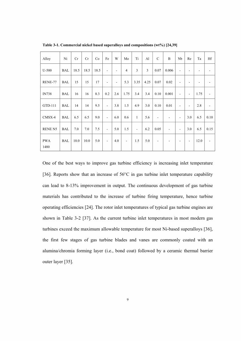
Table 3-1. Commercial nickel based superalloys and compositions (wt%) [24,39] .......... 9
Table 3-2. Rotor inlet temperatures for typical gas turbine engines [37] ......................... 10
Table 3-3. Beneficial and detrimental aspects of alloying elements in metallic coatings
[73,76] ............................................................................................................................... 19
Table 3-4. Ceramic materials and their characteristics [94] ............................................. 25
Table 3-5. Summarized properties of APS, ASPS and EB-PVD coatings [17] ............... 44
Table 4-1. Experimental data for thermophysical properties of IN738 and CMSX-4 (927-
1127C) [152] ................................................................................................................... 50
Table 4-2. Chemical composition of the substrate materials ............................................ 50
Table 4-3. Samples used in isothermal oxidation test ....................................................... 58
Table 4-4. Samples used in cyclic oxidation test .............................................................. 60
Table 5-1. Chemical compositions of PtAl bond coat (layers and substrate near the bond
coat) (wt %) measured by EDS ......................................................................................... 70
Table 6-1. EDS analysis results of Iso#1 (wt % and at %) ............................................... 76
Table 6-2. EDS analysis results of Iso#3 (wt% and at%) ................................................. 78
Table 6-3. EDS analysis results of Iso#2 (wt% and at%) ................................................. 82
Table 6-4. EDS analysis results of Iso#4 (wt% and at%) ................................................. 85
Table 7-1. EDS analysis results of Cyc#1 (wt% and at%) ............................................... 94
Table 7-2. EDS results of Cyc#3 (wt% and at%) ............................................................. 97
Table 7-3. EDS results of Cyc#2 (wt% and at%) ........................................................... 100
Table 7-4. EDS analysis results of Cyc#4 (wt% and at%) ............................................. 103

viii
Table 7-5. Averaged coefficient of thermal expansion (CTE) of substrate, YSZ and TGO
......................................................................................................................................... 107

ix
List of Illustrations
Figure 3-1. Gas turbine and operating principle and applications (A) propulsions for
aircraft and (B) industrial power generation [26] ............................................................... 6
Figure 3-2. Singe-shaft and two-shaft turbines [27] ........................................................... 6
Figure 3-3. Microstructure of a typical Ni-base superalloy [38] ........................................ 8
Figure 3-4. Proportion of alloying element additions to Ni-base alloy from 1965 to 2005
[35] ...................................................................................................................................... 8
Figure 3-5. Thermal barrier coating system for gas turbine application [8] ..................... 11
Figure 3-6. Typical microstructures of plain aluminide coatings, outward-grown (a) and
inward-grown (b) [50]....................................................................................................... 13
Figure 3-7. Ni-Pt-Al phase diagram at 1100C [51] ......................................................... 13
Figure 3-8. Surface rumpling of a (Ni, Pt)Al bond coat [54] ........................................... 14
Figure 3-9. Two layered γ-γ’ NiPtAl coating [60] ............................................................ 15
Figure 3-10. Void formation at bond coat/ TGO interface [63] ....................................... 16
Figure 3-11. Oxidation and hot corrosion performances of different overlay coatings
[66,70,71] .......................................................................................................................... 17
Figure 3-12. Isothermal Ni–Cr–Al ternary phase diagram (a) at 1150°C, (b) at 850°C
[73,75] ............................................................................................................................... 18
Figure 3-13. (a) Maximum crack length vs. TGO thickness under cyclic oxidation. (b)
Maximum crack length vs. number of cycles under cyclic oxidation [88] ....................... 23
Figure 3-14. Crack propagation in the APS coatings at 1050 °C due to discontinuities
opening after 300 cycles (a) and crack propagation associated with the CSN after 500
cycles (b)[88] .................................................................................................................... 23

x
Figure 3-15. Durability of TBC with different concentrations of Y2O3 [97] .................... 26
Figure 3-16. Industrial production system of EB-PVD: 1. Central vapor deposition
chamber; 2. Target storage rooms; 3. Horizontal transmission and rotation components; 4.
Transmission components for target material; 5. Vacuum chamber [99,101] .................. 28
Figure 3-17. ED-PVD equipment and process set up [102] ............................................. 29
Figure 3-18. Scanning electron micrographs of an EB-PVD coating (a) finished surface
[106] and (b) cross section showing its columnar microstructure [105] .......................... 30
Figure 3-19. Thermal conductivity of zirconia and zirconia top coatings applied by EB-
PVD and PS methods [106] .............................................................................................. 30
Figure 3-20. Scanning electron micrograph of EB-PVD top coat cross-section [109] .... 31
Figure 3-21. Effects of the coating thickness on the thermal conductivity of EB-PVD
PYSZ coatings at different temperatures [110] ................................................................ 32
Figure 3-22. (a) Air plasma spray process [118] and (b) A typical plasma-spraying system
with radial power injection system [120].......................................................................... 34
Figure 3-23. Cross section showing microstructure of lamellar APS coating [121] ........ 35
Figure 3-24. Schematic of typical plasma-sprayed coating [114,123] ............................. 36
Figure 3-25. ZrO2-YO1.5 phase diagram [128-130] .......................................................... 38
Figure 3-26. Cross-sections of plasma sprayed agglomerated YSZ powder with an
approximate size of a) 90 μm, b) 50 μm, c) 20 μm [132] ................................................. 39
Figure 3-27. Stages that suspension droplets undergo during the plasma spraying [134] 40
Figure 3-28. Two-zone microstructure of SPS coating [136] ........................................... 41
Figure 3-29. VC YSZ coating (cross section) [144] ......................................................... 43
Figure 3-30. Cross sectional morphology of columnar coating by ASPS method [17] ... 44
xi
Figure 3-31. TGO formed in TBC after 336 h of isothermal oxidation at 950C [148] ... 46
Figure 3-32. Spallation and cracking at top coat/bond coat interface after 336 h of
oxidation at 1050C [148] ................................................................................................. 46
Figure 3-33. Weigh changes of TBCs in a function of oxidation time at 1100C [149] .. 47
Figure 3-34. Surface morphology of YSZ top coat after 300 cycles [150] ...................... 48
Figure 3-35. Weight changes of TBCs with different bond coats as a function of cyclic
oxidation life [151] ........................................................................................................... 49
Figure 4-1: γ/γ’ structure of IN738LC Superalloy ............................................................ 51
Figure 4-2. γ/γ’ structure of CMSX-4 superalloy ............................................................. 52
Figure 4-3. ASPS deposition process [17] ........................................................................ 54
Figure 4-4. Equipment used in sample preparation .......................................................... 56
Figure 4-5. STT-1600C-4-12 high temperature tube furnace used in isothermal oxidation
test ..................................................................................................................................... 57
Figure 4-6. CM Rapid Temp Furnace used in cyclic oxidation test ................................. 59
Figure 4-7. Philips XL30S FEG SEM .............................................................................. 61
Figure 4-8. VegaII-XMU SEM ......................................................................................... 62
Figure 4-9. Bruker AXS D8 Discover Diffractometer for XRD analysis ........................ 63
Figure 5-1. Top surface morphologies of columnar (a and b) and VC coatings (c and d) 65
Figure 5-2. Cross-sections of columnar structured and VC TBC coatings ....................... 65
Figure 5-3. X-ray diffraction pattern from coating top surface before oxidation test ...... 67
Figure 5-4. PtAl bond coat with IN738 (a) and CMSX-4 (b) substrate ............................ 69
Figure 6-1. Isothermal oxidation life (hours) .................................................................... 71

xii
Figure 6-2. Visual observations of Iso#1-4 (every 100 h) ................................................ 73
Figure 6-3. Microstructures of Sample Iso#1 (IN738LC with PtAl + columnar YSZ) after
oxidation test ..................................................................................................................... 75
Figure 6-4. Microstructures of Sample Iso#3 (CMSX-4 with PtAl + columnar YSZ) after
isothermal oxidation test ................................................................................................... 78
Figure 6-5. X-ray diffraction pattern from the backside of the spalled YSZ (Iso#3,
CMSX-4 with PtAl + columnar YSZ) .............................................................................. 79
Figure 6-6. X-ray diffraction pattern of bond coat/substrate (Iso#3, CMSX-4 with PtAl +
columnar YSZ).................................................................................................................. 79
Figure 6-7. Microstructures of sample Iso#2 (IN738LC with PtAl + VC YSZ) after
oxidation test ..................................................................................................................... 81
Figure 6-8. X-ray diffraction pattern from the backside of spalled YSZ (sample Iso#2,
IN738LC with PtAl + VC YSZ) ....................................................................................... 83
Figure 6-9. X-ray diffraction pattern from the exposed bond coat/substrate surface
(sample Iso#2, IN738LC with PtAl + VC YSZ) .............................................................. 83
Figure 6-10. Microstructures of Iso#4 (CMSX-4 with PtAl + VC YSZ) after oxidation
test ..................................................................................................................................... 85
Figure 6-11. X-ray diffraction pattern from the exposed bond/coat substrate surface
(sample Iso#4, CMSX-4 with PtAl + VC YSZ) ............................................................... 86
Figure 7-1. Cyclic oxidation life (in terms of number of cycles) ..................................... 90
Figure 7-2. Visual observations of Cyc#1-4 (images taken every 100 cycles) ................ 92
Figure 7-3. Microstructures of Sample Cyc#1 (IN738LC with PtAl + columnar YSZ)
after oxidation test............................................................................................................. 94

xiii
Figure 7-4. X-ray diffraction pattern from the backside of spalled YSZ (sample Cyc#1,
IN738LC with PtAl + columnar YSZ) ............................................................................. 95
Figure 7-5. X-ray diffraction pattern from the exposed bond coat/substrate surface
(sample Cyc#1, IN738LC with PtAl + columnar YSZ) ................................................... 95
Figure 7-6. Microstructures of Sample Cyc#3 (CMSX-4 with PtAl + columnar YSZ) after
oxidation test ..................................................................................................................... 97
Figure 7-7. X-ray diffraction pattern from the backside of spalled YSZ (sample Cyc#3,
CMSX-4 with PtAl + columnar YSZ) .............................................................................. 98
Figure 7-8. X-ray diffraction pattern from bond coat/substrate surface (sample Cyc#3,
CMSX-4 with PtAl + columnar YSZ) .............................................................................. 98
Figure 7-9. Microstructures of sample Cyc#2 (IN738LC with PtAl + VC YSZ) after
oxidation test ..................................................................................................................... 99
Figure 7-10. X-ray diffraction pattern from the backside of spalled YSZ (Cyc#2,
IN738LC with PtAl + VC YSZ) ..................................................................................... 100
Figure 7-11. X-ray diffraction pattern from the exposed substrate/bond coat surface
(Cyc#2, IN738LC with PtAl + VC YSZ) ....................................................................... 101
Figure 7-12. Microstructures of sample Cyc#4 (CMSX-4 with PtAl + VC YSZ) after
cyclic oxidation test ........................................................................................................ 102
Figure 7-13. X-ray diffraction pattern from the backside of spalled YSZ (Cyc#4, CMSX-
4 with PtAl + VC YSZ) .................................................................................................. 103
Figure 7-14. X-ray diffraction pattern from the exposed bond coat/substrate surface
(Cyc#4, CMSX-4 with PtAl + VC YSZ) ........................................................................ 104
Figure 7-15. Failure of TGO due to thermal expansion mismatch ................................. 106

xiv
Figure 7-16. Mean coefficient of expansion (CTE) of different types of Ni-base
superalloys [151] ............................................................................................................. 107
xv
Nomenclature
APS Air plasma spray
ASPS Axial suspension plasma spray
CMSX-4 A single crystal Ni-based superalloy manufactured by Canon Muskogan
CS Cr2O3 and spinel
CSN Cr2O3, spinel and NiO
CTE Coefficient of thermal expansion
EB-PVD Electron beam physical vapor deposition
IDZ Inter-diffusion zone
IN738 Inconel 738 Ni-based superalloy manufactured by Inco Ltd.
OEM Original equipment manufacturer
PS Plasma spray
SEM Scanning electron microscope
SOD Stand-off distance
SPS Suspension plasma spray
TBC Thermal barrier coating
TCP Topologically close-packed
TGO Thermally grown oxide
VC Vertical crack
XRD X-ray diffraction
YSZ Yttria-stabilized zirconia
1
1 Chapter: Introduction
Modern gas turbines operate at high temperature and constantly increasing the inlet
temperature is required to improve turbine efficiency [1,2]. The hot sections of gas
turbines are subjected to not only high temperature [3], but also severe oxidizing and
corrosive environments [4]. Therefore, the efficiency of a gas turbine engine is highly
dependent on the thermal and mechanical properties of the materials used for the hot
section components such as the turbine blades [5]. Nickel-based superalloys are widely
used for gas turbine blades due to their high temperature resistance and high strength at
elevated temperature. These superalloys can work for thousands of hours even at a high
temperature of 1100C [6]. With the application of thermal barrier coatings (TBCs) on
gas turbine blades and vanes, metal surface temperature can be reduced by 100C to
300C, depending upon thickness, composition and structure, leading to a significant
increase of turbine efficiency [7,8].
Combining the low thermal conductivities of YSZ and the excellent oxidation/corrosion
resistance of bond coat, thermal barrier coating systems prevent superalloy substrate from
many different types of environmental degradation [7]. There are two typical types of
bond coats: traditional MCrAlY (M=Ni or/and Co) overlay coatings and platinum-
modified aluminum (PtAl) diffusion coatings [8]. PtAl coatings have exhibited better
protection against high temperature oxidation damage than MCrAlY coatings due to their
ability to form a slow-growing alumina scale [9]. The addition of platinum to the
aluminide coating improves the oxidation resistance by promoting selective oxidation of
aluminum and enhances coating stability and scale adhesion in return [10].

2
The YSZ ceramic top coats are usually deposited by the air plasma spraying (APS)
method or electron beam physical vapor deposition (EB-PVD) technique. APS method is
a more commonly used commercial deposition technique for gas turbine blades due to its
low cost, high deposition rate and large range of applicable coating compositions [11].
The YSZ coatings deposited by APS exhibit high thermal resistance because of the
inherent laminar structure [12]. However, the presence of porosity and micro-cracks and
the lack of strain tolerant microstructure features in the traditional APS coatings lead to
coating spallation during exposure to high temperature, particularly under cyclic
conditions [13]. On the contrary, EB-PVD deposited YSZ coatings have shown superior
strain and thermo-shock tolerance due to columnar microstructures. They also exhibit
better resistance to spallation, lower surface roughness, better thickness uniformity and
superior adherence to the substrate over those processed by plasma spraying [14].
However, the equipment costs of EB-PVD systems are much higher than plasma spraying
ones and the deposition rate is relatively low [15,16].
More recently, a new axial suspension plasma spray (ASPS) technology has emerged;
with this new technology, more durable TBCs with comparable performance as EB-PVD
can be produced with lower equipment and operating costs. Some of the coatings
produced using ASPS, such as that with columnar ASPS structure, exhibit much higher
bond strength to bond coat and better strain tolerance than APS coatings, although the
thermal insulation capability may be slightly compromised [17]. In traditional suspension
plasma spraying, fine particles (usually in nm scale) suspended in a liquid carrier are
injected directly into the plasma stream, instead of powder injection; in the case of ASPS,
the suspension liquid is injected axially, providing more acceleration to the suspension

3
[18]. The ASPS deposition process, through controlling the processing parameters, can
produce coatings with columnar structure or dense coatings with vertical cracks (VCs).
For example, while columnar structured coatings are deposited with a longer stand-off
distance (SOD), dense coatings having more thermal insulation with vertical cracks for
better strain tolerance can be produced with a shorter SOD [17]. Similar to the columnar
structure, VC reduces the tensile stress in the YSZ top coat upon heating and compressive
stress upon cooling [19]. Therefore, VC and columnar coatings usually have longer
oxidation lives than lamellar APS coatings.
The oxidation behaviors of TBCs are influenced by many factors. It was reported that
large variations of TBC life are caused by the difference in rates of interdiffusion, Al
depletion and TGO growth and affected by substrate materials [20]. Life of a TBC can be
reduced by the formation of Kirkendall porosity at substrate/bond coat interface [21], and
the spallation of top coat because of forming mixed oxides and spinels [22]. The thermal
cycling rate also affects TBC lifetime [23]. However, ASPS TBC coatings with different
structures (laminar, VC and columnar) under both isothermal and cyclic conditions have
not been systematically characterized and well understood. The objective of this work is
to investigate the effects of substrate composition and top coat microstructure on both
isothermal and cyclic lifetimes of ASPS TBCs.

4
2 Chapter: Research Objectives
Currently, there is a lack of systematic evaluation of TBC coatings with different
substrate material and top coat structures, including laminar-structured APS coatings,
VC- or columnar- structured ASPS coatings, under both isothermal and cyclic conditions.
Additionally, since the top coat, bond coat and substrate form an integrated part, the
change in bond coat or substrate composition will also have impact on the performance of
a system. As such, this research was initiated with the following objectives:
I. To study the isothermal/cyclic oxidation behaviors and microstructure changes of
three different types of thermal barrier coatings (TBCs): conventional APS,
vertically cracked and columnar-structured ASPS coatings.
II. To characterize the effects of substrates (CMSX-4 vs. IN738) on the isothermal
and cyclic oxidation behaviors of different TBC systems.
III. To analyze the isothermal and cyclic oxidation failure mechanisms of various
TBC coating systems.
IV. To recommend to industry the preferable combination of substrate, bond coat and
ASPS ceramic top coat based on the TBC systems studied.

5
3 Chapter: Literature Review
3.1 Gas Turbines and Blade Materials
Modern gas turbine engines are mainly employed for aircraft propulsion and industrial
power generation [24]. A gas turbine engine mainly consists of three sections: a
compressor, a combustion chamber and a turbine. The compressor draws in air and
compresses it to a high pressure level for the combustion process; the compressed air and
fuel are mixed, ignited and burned in the combustion chamber; the expanded air flow is
then blown out though the exhaust nozzle [25]. There are two types of power which can
be generated by a gas turbine: thrust power, which is used in aviation as aircraft
propulsion, and shaft power, which is produced by land-base gas turbine for industrial
application, as shown schematically in Figure 3-1 [26]. Gas turbines can also be
classified into single-shaft and two-shaft turbine (Figure 3-2). In the single-shaft turbine,
the turbine drives both compressor and power coupling by the same shaft, whereas in a
two-shaft turbine, the compressor is decoupled from shaft, and is driven by the gas
generator turbine before the power turbine. The single-shaft gas turbine is mainly used
for electricity generation due to the requirement of constant speed while two-shaft turbine
is usually applied in propulsion applications as the speed and load vary [27].

6
Figure 3-1. Gas turbine and operating principle and applications (A) propulsions for aircraft and (B)
industrial power generation [26]
Figure 3-2. Singe-shaft and two-shaft turbines [27]

7
The efficiency of a gas turbine engine highly depends on the thermal and mechanical
properties of the materials used for the hot section components such as the turbine blades
[5]. However, the turbine blades are subjected not only to high temperature [3], but also
to severe oxidizing and corrosive environments [4]. The severe operating environment
can cause damage to the blades due to oxidation, corrosion and erosion, and consequently
reduce the blade life [28]. Moreover, creep failure can occur to the blades that are under
stresses due to centrifugal load and vibration caused by high speed rotation [29,30].
Fatigue failure is another common failure of turbine blade due to frequent engine starts
and shutdowns [31]. Therefore, blade materials must exhibit high thermal shock and
oxidation resistance, and maintain high strength at elevated temperature [32].
Nickel-based superalloys, with a microstructure containing γ’ (Ni3Al) cubical precipitates
embedded in the γ phase Ni-base matrix [33] (Figure 3-3), are widely used for gas turbine
blades due to their high temperature capability and high strength at elevated temperature
that allow them to sustain thousands of hours of loading at a high temperature near
1100C [6]. In addition to nickel, Ni-base superalloy also contains chromium and cobalt
for improving the corrosion resistance, and aluminum, for high oxidation resistance
through forming a protective alumina scale [34]. Refractory elements such as
molybdenum, tantalum, tungsten and rhenium are also included to improve high
temperature mechanical strength. Since 1965, the Cr content has been gradually
decreased from 15 wt% to 3wt %, due to the need to stabilize high temperature
microstructure and prevent TCP phase formation, and the amount of Al and refractory
elements has increased, as shown in Figure 3-4 [35]. These compositional changes have
increased the demand on coating materials to provide corrosion/oxidation resistance for

8
gas turbine blade materials. A summary of the common Ni-base superalloys used in gas
turbine are provided in Table 3-1 [24,39].
Figure 3-3. Microstructure of a typical Ni-base superalloy [38]
Figure 3-4. Proportion of alloying element additions to Ni-base alloy from 1965 to 2005 [35]
9
Table 3-1. Commercial nickel based superalloys and compositions (wt%) [24,39]
Alloy Ni Cr Cr Co Fe W Mo Ti Al C B Nb Re Ta Hf
U-500 BAL 18.5 18.5 18.5 - - 4 3 3 0.07 0.006 - - - -
RENE-77 BAL 15 15 17 - - 5.3 3.35 4.25 0.07 0.02 - - - -
IN738 BAL 16 16 8.3 0.2 2.6 1.75 3.4 3.4 0.10 0.001 - - 1.75 -
GTD-111 BAL 14 14 9.5 - 3.8 1.5 4.9 3.0 0.10 0.01 - - 2.8 -
CMSX-4 BAL 6.5 6.5 9.0 - 6.0 0.6 1 5.6 - - - 3.0 6.5 0.10
RENE N5 BAL 7.0 7.0 7.5 - 5.0 1.5 - 6.2 0.05 - - 3.0 6.5 0.15
PWA
1480
BAL 10.0 10.0 5.0 - 4.0 - 1.5 5.0 - - - - 12.0 -
One of the best ways to improve gas turbine efficiency is increasing inlet temperature
[36]. Reports show that an increase of 56C in gas turbine inlet temperature capability
can lead to 8-13% improvement in output. The continuous development of gas turbine
materials has contributed to the increase of turbine firing temperature, hence turbine
operating efficiencies [24]. The rotor inlet temperatures of typical gas turbine engines are
shown in Table 3-2 [37]. As the current turbine inlet temperatures in most modern gas
turbines exceed the maximum allowable temperature for most Ni-based superalloys [36],
the first few stages of gas turbine blades and vanes are commonly coated with an
alumina/chromia forming layer (i.e., bond coat) followed by a ceramic thermal barrier
outer layer [35].

10
Table 3-2. Rotor inlet temperatures for typical gas turbine engines [37]
Engine Rotor inlet temp. /°C
Power output /MW
Predicted efficiency/ %
Westinghouse 501G 1426 240 58
Siemens V84/3a 1310 170 57
Alston GT26 1240 281 57
GE 7FA 1290 150 55
3.2 Thermal Barrier Coating System
Thermal barrier coatings (TBCs) are nowadays widely applied to gas turbine blades and
vanes to provide oxidation and hot corrosion protection [40]. The state-of-the-art TBC
system usually consists of a metallic bond coat and a ceramic top coat of partially
yttrium-stabilized zirconia (YSZ) (Figure 3-5) [8]. A scale of thermally grown oxide
(TGO), usually alumina in nature, forms between the ceramic top coat and bond coat
after oxidation. The insulating property of yttria-stabilized zirconia (YSZ) ceramic
coatings and the oxidation and corrosion resistance of the metallic bond coat can together
provide environmental protection and achieve a reduction of surface temperature up to
100 to 300C. With the use of TBC system, the performance and efficiency of gas turbine
engines are greatly improved [7,8].

11
Figure 3-5. Thermal barrier coating system for gas turbine application [8]
3.2.1 Bond Coat
Bond coat is applied to enhance the hot corrosion and oxidation resistance of the
superalloy substrate. Thus it must have high resistance against oxidation and corrosion,
the required interface stability and coating adhesion as well as suitable mechanical
strength. The bond coat is normally 75- 150 μm in thickness [8,41]. The usual bond coat
forms a thin, adherent, and dense TGO layer on the surface upon exposure to oxygen
[42]. There are two typical bond coatings: aluminide diffusion coatings (such as
platinum-modified aluminium diffusion coatings) and MCrAlY (M=Ni or/and Co)
overlay coatings [43].
3.2.1.1 Aluminide Diffusion Bond Coat
Aluminide diffusion coatings have exhibited good protection against high temperature
oxidation damage. The addition of platinum to the aluminide coating can improve the
oxidation resistance by further promoting selective oxidation of aluminium, enhancing

12
scale adhesion, and stabilizing interdiffusion between bond coat and substrate [10,44,45].
The Pt addition can also help to reduce the void growth along the TGO/bond coat
interface and modify the morphology of TGO and bond coat/substrate [46,47]. R.
Swadzba et al. examined the effects of Pt-modified coatings on the cyclic oxidation
resistance of coated system and found that the oxide layer formed on the Pt-modified
aluminide coating exhibited better adhesion in comparison to simple aluminide coatings
and was able to maintain an oxide layer with higher amount of desirable α-alumina [48].
Aluminide coatings can exhibit a two-layer or three-layer structure, which are inward-
grown (Al diffusion inwards) and outward-grown (Ni and other substrate elements
outward diffusion) respectively. Two-layer structure consists of an outer layer and an
inner interdiffusion zone (IDZ) (Figure 3-6 (a)) while three-layer structure has an
intermediate layer between outer and inner layer (Figure 3-6 (b)) [49,50].
For Pt-aluminide coatings, the phase in the outer layer is dependent on both Pt and Al
compositions, as shown in Figure 3-7 [51]. β-(Ni,Pt)Al is the most common phase in the
outer layers [50,52]. The outer layer can also exhibit single phase ξ-PtAl2 or a mixed ξ +
β structure. The intermediate layer usually exhibits β phase (with Pt in solid solution) and
some fine precipitates. More precipitates can be found in the IDZ. Pt concentration in
each layer is determined by the thickness of Pt layer and the ensuing heat treatment [49].
It is reported that there exists an optimum level of Pt content in β-(Ni,Pt)Al coatings,
beyond which a brittle ξ phase will form [53].

13
Figure 3-6. Typical microstructures of plain aluminide coatings, outward-grown (a) and inward-
grown (b) [50]
Figure 3-7. Ni-Pt-Al phase diagram at 1100C [51]

14
Despite its protective nature, β-(Ni,Pt)Al coatings for Ni-base superalloy will degrade
over time due to Al depletion and elemental inter-diffusion between coating and the
substrate. Surface rumpling (Figure 3-8) and detrimental phase transformation in β-
(Ni,Pt)Al coatings can lead to coating spallation and failure of TBC system [54,55].
Rumpling usually occurs during thermal cycling oxidation when the bond coat is
subjected to repeated heating and cooling. Balint et al. reported that thermal expansion
mismatch and phase transformation in the bond coat induce large stresses and the bond
coat is especially susceptible to rumpling during thermal exposure [56].
Figure 3-8. Surface rumpling of a (Ni, Pt)Al bond coat [54]
Compared to β-(Ni,Pt)Al, γ-γ’ NiPtAl coatings can form adherent alumina scales with
significantly reduced rumpling during thermal cycling. Furthermore, since Ni-based
superalloys also have the typical γ-γ’ phase, γ-γ’ NiPtAl coatings are more compatible
with substrate in terms of phase constitution and thermal expansion, which is beneficial
to TBC life [57,58]. γ-γ’ NiPtAl coatings usually show good high temperature oxidation
resistance and increased amount of Pt can improve the adherence of scale [59]. But γ-γ’
15
NiPtAl coatings are very sensitive to oxidation temperature and superalloy substrate
composition [55].
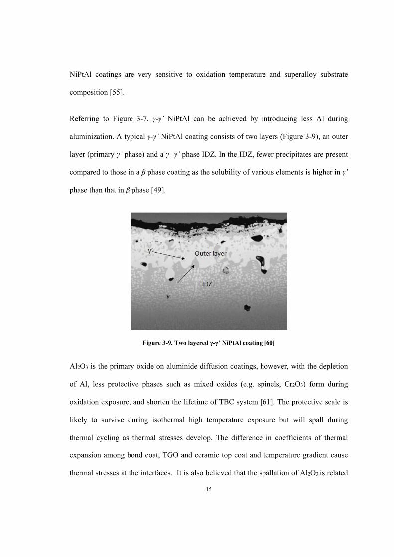
Referring to Figure 3-7, γ-γ’ NiPtAl can be achieved by introducing less Al during
aluminization. A typical γ-γ’ NiPtAl coating consists of two layers (Figure 3-9), an outer
layer (primary γ’ phase) and a γ+γ’ phase IDZ. In the IDZ, fewer precipitates are present
compared to those in a β phase coating as the solubility of various elements is higher in γ’
phase than that in β phase [49].
Figure 3-9. Two layered γ-γ’ NiPtAl coating [60]
Al2O3 is the primary oxide on aluminide diffusion coatings, however, with the depletion
of Al, less protective phases such as mixed oxides (e.g. spinels, Cr2O3) form during
oxidation exposure, and shorten the lifetime of TBC system [61]. The protective scale is
likely to survive during isothermal high temperature exposure but will spall during
thermal cycling as thermal stresses develop. The difference in coefficients of thermal
expansion among bond coat, TGO and ceramic top coat and temperature gradient cause
thermal stresses at the interfaces. It is also believed that the spallation of Al2O3 is related
16
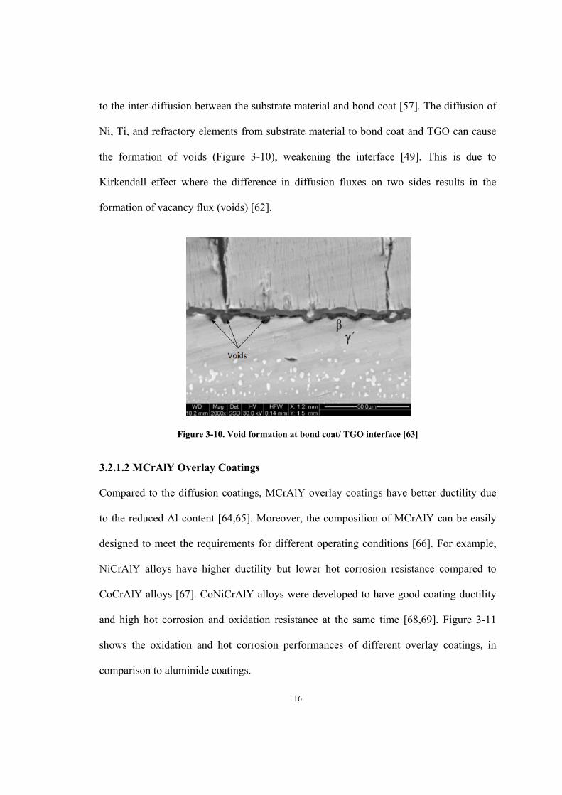
to the inter-diffusion between the substrate material and bond coat [57]. The diffusion of
Ni, Ti, and refractory elements from substrate material to bond coat and TGO can cause
the formation of voids (Figure 3-10), weakening the interface [49]. This is due to
Kirkendall effect where the difference in diffusion fluxes on two sides results in the
formation of vacancy flux (voids) [62].
Figure 3-10. Void formation at bond coat/ TGO interface [63]
3.2.1.2 MCrAlY Overlay Coatings
Compared to the diffusion coatings, MCrAlY overlay coatings have better ductility due
to the reduced Al content [64,65]. Moreover, the composition of MCrAlY can be easily
designed to meet the requirements for different operating conditions [66]. For example,
NiCrAlY alloys have higher ductility but lower hot corrosion resistance compared to
CoCrAlY alloys [67]. CoNiCrAlY alloys were developed to have good coating ductility
and high hot corrosion and oxidation resistance at the same time [68,69]. Figure 3-11
shows the oxidation and hot corrosion performances of different overlay coatings, in
comparison to aluminide coatings.

17
Figure 3-11. Oxidation and hot corrosion performances of different overlay coatings [66,70,71]
MCrAlYs are further classified into FeCrAlY, NiCrAlY, CoCrAlY and CoNiCrAlY.
FeCrAlY coating compositions were the first MCrAlYs investigated. One particular alloy
had the composition of Fe–25%Cr–4%Al–1.0%Y when it was developed at General
Electric during the nuclear programs in the 1960s [66,67]. This alloy exhibited
exceptional bonding to alumina scale under cyclic oxidation condition as it assumes a
body-centered cubic (BCC) structure, instead of a face-centered cubic (FCC) structure as
most of the other overlay coatings [42]. The addition of yttrium in the MCrAlY in general
helps improve the bond coat adhesion by segregating to the bond coat/TGO interface and
increase oxidation resistance [72]. Due to the increased utilization of Ni- and Co- base
superalloys in gas turbines, NiCrAlY, CoCrAlY and CoNiCrAlY were developed to
match the substrate composition/microstructure [66]. They all exhibit excellent oxidation
and corrosion resistance in high temperature oxidizing environment, which makes them
the preferred materials for bond coatings used in TBC systems[67].

18
Ni-base MCrAlY type of coatings usually consists of either β-NiAl phase or β-aluminide
phase in a γ solution matrix. The oxidation and hot corrosion behavior, as well as phase
stability, are associated with the β/γ phase ratio. As shown in a Ni–Cr–Al ternary phase
diagram (Figure 3-12), the β+γ phase field indicates desired composition of MCrAlY
coatings. When the temperature reduces from 1150°C to 850°C, the MCrAlY (with
composition represented by the small square) transforms from β+γ to α-(Cr)+γ’; this
phase change is accompanied by a significant volume change due to thermal expansion.
Addition of appropriate amount of Co can help reduce the volume change and improve
the ductility of MCrAlY bond coatings [73].
Figure 3-12. Isothermal Ni–Cr–Al ternary phase diagram (a) at 1150°C, (b) at 850°C [73,75]
Similarly, the concentration of Al affects the performance of bond coat as well. Brandl et
al. had carried out isothermal tests on NiCoCrAlY with 8 wt% and 12 wt% Al in air and
in He with 1% O2. The results showed that the oxide scale on the coatings with 8 wt% Al
had cracked after 500 h while for the coating with 12wt% Al, the scale was still uniform
even after 4000 h [74]. The beneficial and detrimental aspects of several alloying

19
elements in MCrAlY coatings are summarized in Table 3-3. MCrAlY bond coats are
usually deposited using thermal spray or electron-beam physical-vapor deposition
method [8]. The details of deposition methods are further discussed in the next section.
Table 3-3. Beneficial and detrimental aspects of alloying elements in metallic coatings [73,76]
Elemental Constituent
Beneficial Aspects Detrimental Aspects
Ni Major constituent of substrate alloy. Provides strength.
Prone to destructive interaction with sulfur.
Co Major constituent of substrate alloy. Provides microstructural stability and strength.
Prone to destructive interaction with sulfur.
Al Constituent of substrate alloy. Major contributor to strengthening. Contributes to oxidation resistance.
Large concentration lowers melting point.
Cr Constituent of substrate alloy. Contributes to oxidation resistance to 1500°F (816°C). Reduces Al requirement for formation of alumina scale. Imparts resistance to hot corrosion.
Lowers creep strength.
Ta Enhances hot corrosion and oxidation resistance. Improves strength.
Si Enhances oxidation and type II hot corrosion resistance.
Large concentration leads to formation of brittle phases.
Hf, Y, Y2O3, oxides of other reactive elements
Improves adherence of alumina and chromia scales.
Large amounts are detrimental.
Pt Improves oxidation and hot corrosion resistance.
3.2.1.3 Bond Coat Application Process
For overlay coatings, aluminizing can be accomplished by using thermal spraying
methods, chemical vapor deposition (CVD) or physical vapor deposition (PVD). In all of
the thermal spraying methods, a fine powder is heated and melted, and then injected to
20
impact with the cool substrate, where it solidifies. In CVD method, a chemical process
takes place when in contact with a heated material and the reaction leads to
condensation/deposition. PVD processes are further divided into thermal evaporation, ion
sputtering and ion plating [77]. In thermal evaporation process, the metallic material is
evaporated at high temperature and high vacuum level, and the vapor is condensed on the
cool substrate surface. Ion sputtering uses a cathode electrode to emit atoms and atomic
clusters (sputter) so that the substrate material is bombarded by positive ions and
energetic particles. In ion plating process, an electron beam is used to evaporate the target
material. The metal vapor is then ionized partially to increase the coating adhesion [77].
Pack and slurry cementation processes are the most commonly used methods for
aluminide diffusion coating deposition. It is based on the following reaction:
Al + NH4Cl →AlCl (g) →Al (1)
The pack powder usually consists of pure Al powder, α-Al2O3 filler and NH4Cl activator,
and parts to be coated are buried within the powder during coating process. When pack
powder materials are suspended in a binder, it forms a slurry which can be coated onto
the substrate by dipping or spraying before being heated [77,78]. A post coating heat
treatment is then applied to obtain good bonding between substrate and bond coat and
encourage diffusion. For PtAl diffusion coatings, a platinum layer is first deposited by
electroplating and followed by a diffusion heat treatment. After plating of platinum,
aluminide coating is then applied [79,80].

21
3.2.2 TGO
Thermally grown oxide (TGO) is a thin oxidized layer (1-10 μm in thickness) formed
between top coat and bond coat as a result of high temperature oxidation [8]. The oxygen
is either from hot gas penetrating through porosities and microcracks in the top coat or
the downward and upward diffusion of oxygen ions from coatings themselves [81]. TGO
consists mainly of α-Al2O3 and other minor Cr/Ni-containing oxides as well as NiAl2O4
spinels. Since the diffusion rate of ions in α-Al2O3 is slow, a continuous α-Al2O3 scale
can suppress TGO growth during oxidation. Therefore α-alumina is the most desirable
constituent of TGO [82]. This oxide scale can protect the substrate from further
oxidation. A fast growing TGO, however, can impose stresses on the interfaces of TGO/
bond coat and TGO/ top coat leading to crack linkage and propagation and eventually the
failure of TBCs [81,83]. It was reported that the formation of porous spinel and nickel
oxide causes large volume expansion and tensile stress, contributing to the failure of
TBCs [82].
TGO growth plays an important role in the ultimate failure of TBC system. Defects
coupled with stress and TGO waviness are thought to be the main reason why small
cracks can grow and cause the spallation of top coat [84,85]. Chen et al. have found that
the TGO with a stable Al2O3 layer had a low growth rate and less tendency for crack
propagation, which led to better TBC durability [86]. There exists an Al-depletion
criterion based on the combined time and temperature for MCrAlY bond coatings; if the
aluminum concentration falls to about 8 at%, other mixed oxides and spinels will grow
and these mixed oxides and spinels cannot act as a protective scale, resulting in increased
oxidation rate [87]. According to Buschinelli et al., three types of defects were found

22
during TGO growth under thermal cycling: vertical columnar cracks, cavities and
horizontal cracks parallel to TGO. Among the three imperfections, horizontal cracks were
believed to be the main reason for the TBC failure [83]. The TGO thickness showed an
increasing relationship with maximum crack length, or vice versa (Figure 3-13 (a)). The
maximum crack length also increased with the increasing number of cycles as shown in
(Figure 3-13 (b)) [88].
TGO growth during cyclic test follows a three-stage course. A rapid TGO growth occurs
at the beginning of oxidation, followed by a nearly linear growth, and finally an
accelerated growth ensues (very similar to the creep deformation mechanism). The last
stage is related to heterogeneous and substantial growth of mixed oxides and spinels [88].
Crack nucleation and void formation are usually located near oxide cluster and spinels
(CS) layer [89], as shown in Figure 3-14 (a). The discontinuities which are common in
APS coatings can also develop into fully open cracks (Figure 3-14 (b)) [88]. This
evidence indicates that the formation of non-protective oxides and discontinuities are
detrimental to the life of TBC systems [86].
Toscano at al. stated that the rate of yttrium depletion is another important lifetime
governing factor. They found that yttrium partitioning in alumina based TGO increased
the TGO growth rate and resulted in the loss of yttrium in the coating [90]. When the
concentration of yttrium in the coatings is under a critical level, it can no longer improve
the adherence of TGO, leading to the failure of TBCs. The time required for yttrium
exhaustion is related to both initial yttrium content and the total yttrium reservoir, which
is proportional to the bond coat thickness [90].

23
(a) (b)
Figure 3-13. (a) Maximum crack length vs. TGO thickness under cyclic oxidation. (b) Maximum
crack length vs. number of cycles under cyclic oxidation [88]
Figure 3-14. Crack propagation in the APS coatings at 1050 °C due to discontinuities opening after
300 cycles (a) and crack propagation associated with the CSN after 500 cycles (b) [88]
TGO growth plays a controlling role in TBC lifetime. Therefore, in order to improve the
performance of TBC system, all factors such as Al or Y depletion, growth of chromia,
spinels, NiO (CSN), and thickening of TGO layers must be characterized. Improvement
to TBC deposition techniques, bond coat compositions and pre-oxidation treatments are
some of the approaches used to prolong TBC’s durability. Baufeld et al. investigated the
effect of pre-treatments on Pt-Al bond coats before the deposition of ceramic top coats.

24
Under cyclic thermal test with a maximum temperature of 1100°C and a cycle length of 1
hour, the result showed that the specimens annealed at 1080°C for 4 hours either in
vacuum or ArH atmosphere had significant longer lifetimes (2-3 times longer) than those
without pre-treatment [91].
3.2.3 Ceramic Top Coat
The top coat provides thermal insulation to the metallic substrate and prolongs the
lifetime of the hot components of aero- and land-based gas turbines, in combination with
the internal cooling scheme. Ceramic coatings have low thermal conductivities, usually in
the order of several W/m.K [92]. There are some basic requirements for the ceramic top
coats, such as low thermal conductivities, high melting points, absence of phase
transformation between room temperature and working temperature, thermal expansion
matching to bond coat material, good adherence to the bond coat and low sintering rate
[92,93,94]. Among those factors, thermal expansion coefficient (CTE) and thermal
conductivity are the most important properties for selecting ceramic top coat material
[92,95,96]. Table 3-4 shows the characteristics of different ceramic materials [94].

25
Table 3-4. Ceramic materials and their characteristics [94]
Materials Advantages Disadvantages
7–8 YSZ (1) high thermal expansion coefficient (2) low thermal conductivity (3) high thermal-shock resistance
(1) sintering above 1473 K (2) phase transformation (1443 K) (3) corrosion (4) oxygen-transparent
Mullite (3Al2O3·2SiO2)
(1) high corrosion resistance (2) low thermal conductivity (3) good thermal-shock resistance below 1273 K
(1) crystallization (1023–1273 K) (2) very low thermal expansion coefficient
Alumina (Al2O3)
(1) high corrosion resistance (2) high hardness (3) not oxygen-transparent
(1) phase transformation (1273 K) (2) high thermal conductivity (3) very low thermal expansion coefficient
YSZ + CeO2 (1) high thermal expansion coefficient (2) low thermal conductivity (3) high corrosion resistance (4) less phase transformation between m and t phase than YSZ (5) high thermal-shock resistance
(1) increased sintering rate (2) CeO2 precipitation (>1373 K) (3) CeO2-loss during spraying
La2Zr2O7 (1) very high thermal stability (2) low thermal conductivity (3) low sintering rate (4) not oxygen-transparent
(1) relatively low thermal expansion coefficient
La2Ce2O7 (1) very high thermal stability (2) high thermal expansion coefficient (3) low thermal conductivity (4) high corrosion resistance
(1) CeO2-loss during spraying (2) relatively high sintering rate (>1523 K)
Silicates (1) cheap, readily available (2) high corrosion resistance
(1) decomposition into ZrO2 and SiO2 during thermal spraying (2) very low thermal expansion coefficient
SrZrO3 (1) high thermal expansion coefficient (2) low thermal conductivity (3) low sintering rate
(1) phase transformations (2) SrO-loss during spraying
26
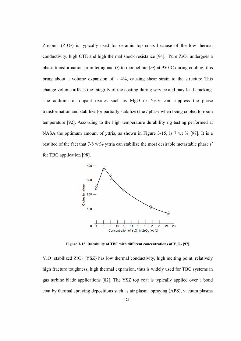
Zirconia (ZrO2) is typically used for ceramic top coats because of the low thermal
conductivity, high CTE and high thermal shock resistance [94]. Pure ZrO2 undergoes a
phase transformation from tetragonal (t) to monoclinic (m) at 950C during cooling; this
bring about a volume expansion of ~ 4%, causing shear strain to the structure This
change volume affects the integrity of the coating during service and may lead cracking.
The addition of dopant oxides such as MgO or Y2O3 can suppress the phase
transformation and stabilize (or partially stabilize) the t phase when being cooled to room
temperature [92]. According to the high temperature durability rig testing performed at
NASA the optimum amount of yttria, as shown in Figure 3-15, is 7 wt % [97]. It is a
resulted of the fact that 7-8 wt% yttria can stabilize the most desirable metastable phase t’
for TBC application [98].
Figure 3-15. Durability of TBC with different concentrations of Y2O3 [97]
Y2O3 stabilized ZrO2 (YSZ) has low thermal conductivity, high melting point, relatively
high fracture toughness, high thermal expansion, thus is widely used for TBC systems in
gas turbine blade applications [82]. The YSZ top coat is typically applied over a bond
coat by thermal spraying depositions such as air plasma spraying (APS), vacuum plasma
27
spraying (VPS), or by electron beam physical vapor deposition (EB-PVD) [42]. The
techniques for top coat deposition are introduced in the next subsection.
3.3 Techniques for YSZ Ceramic Top Coating Deposition
3.3.1 Electron Beam Physical Vapor Deposition (EB-PVD)
Physical vapor deposition for TBCs has been investigated by many researchers from US,
UK, Germany and countries of the former Soviet Union since the 1980s. A significant
development of this technique emerged in the 1990s, when the Paton Welding Institute in
Ukraine invented a new EB-PVD technology which decreased the costs of this deposition
method. Since then the EB-PVD technique has been widely applied to produce thermal
barrier coatings by many OEMs [99].
TBCs produced by EB-PVD have shown a superior strain and thermo-shock tolerance
due to the inherent columnar microstructures. They also exhibit good resistance to
spallation, low surface roughness, high thickness uniformity and good adherence to the
substrate over those processed by plasma spraying, and became the most promising
protective coatings for stressed parts in the hot sections of gas turbine engines. The
equipment and process costs of EB-PVD are much higher than APS but the superior
performance of EB-PVD TBCs justifies its use for critical components such as turbine
blades [15,16].
3.3.1.1 EB-PVD Equipment and Deposition Process
EB-PVD technology introduces an electron beam as a heat source. First, an electron
beam is formed at 2000°C in an electron gun, and then the electrons are accelerated by
high voltage. When the target material is hit by the high-speed electrons, it starts to melt

28
and vaporize; the vapour is directed to and deposits onto the substrate in a low pressure
environment. EB-PVD method has a higher deposition rate and leads to a much stronger
bonding between deposited coating and substrate than those deposited by APS method.
Moreover, since the deposition parameters such as electron beam power, beam spot size
and location can be easily controlled, it is possible for EB-PVD to obtain a coating with
uniform thickness and smooth surface [100].
An example of EB-PVD system, which consists of one central vapor deposition chamber
(main chamber), pre-vacuum chambers and electronic guns, is illustrated Figure 3-16
[99,101]. Among these guns one is for pre-heating the substrate materials in order to
achieve the right deposition condition and the others are used for melting and evaporating
the target materials. There are also vertical and horizontal transmission components and
three water-cooled crucibles for target materials. The work piece can be fed into the main
chamber by valves [99]. The pressure in the vacuum chamber is usually 10-3 torr to avoid
collision between air and deposition atoms as well as reaction with N and O. Figure 3-17
shows a typical EB-PVD facility and deposition process.
Figure 3-16. Industrial production system of EB-PVD: 1. Central vapor deposition chamber; 2.
Target storage rooms; 3. Horizontal transmission and rotation components; 4. Transmission
components for target material; 5. Vacuum chamber [99,101]

29
Figure 3-17. ED-PVD equipment and process set up [102]
3.3.1.2 Microstructure of EB-PVD Coatings
TBCs deposited by EB-PVD technique have a unique columnar microstructure (Figure 3-
18) which provides superior tolerance against stresses, erosion and thermo shock, thus
having a longer lifetime than those deposited by plasma spraying method [16]. The
columnar grains can also suppress the cracking in TBCs parallel to the metallic-bonding
layer interface [103,104]. However, this columnar structure, as demonstrated in Figure 3-
19, has the disadvantage of a high thermal conductivity when compared to laminar
structure, which is the inherent structure of APS due to the impact of molten powder
particles. Thus one of the challenges for EB-PVD coatings is to lower the thermal
conductivity through microstructure modification and composition optimization
[105,106].

30
(a) (b)
Figure 3-18. Scanning electron micrographs of an EB-PVD coating (a) finished surface [107] and (b)
cross section showing its columnar microstructure [105]
Figure 3-19. Thermal conductivity of zirconia and zirconia top coatings applied by EB-PVD and PS
methods [106]
31
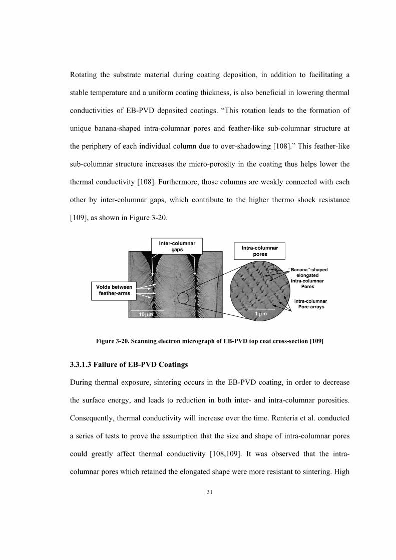
Rotating the substrate material during coating deposition, in addition to facilitating a
stable temperature and a uniform coating thickness, is also beneficial in lowering thermal
conductivities of EB-PVD deposited coatings. “This rotation leads to the formation of
unique banana-shaped intra-columnar pores and feather-like sub-columnar structure at
the periphery of each individual column due to over-shadowing [108].” This feather-like
sub-columnar structure increases the micro-porosity in the coating thus helps lower the
thermal conductivity [108]. Furthermore, those columns are weakly connected with each
other by inter-columnar gaps, which contribute to the higher thermo shock resistance
[109], as shown in Figure 3-20.
Figure 3-20. Scanning electron micrograph of EB-PVD top coat cross-section [109]
3.3.1.3 Failure of EB-PVD Coatings
During thermal exposure, sintering occurs in the EB-PVD coating, in order to decrease
the surface energy, and leads to reduction in both inter- and intra-columnar porosities.
Consequently, thermal conductivity will increase over the time. Renteria et al. conducted
a series of tests to prove the assumption that the size and shape of intra-columnar pores
could greatly affect thermal conductivity [108,109]. It was observed that the intra-
columnar pores which retained the elongated shape were more resistant to sintering. High

32
aspect-ratio, high density intra-columnar pore arrays also contributed to lower thermal
conductivity and higher resistance against thermal property degradation. In addition to
porosity, the thickness of the coating also affects thermal conductivity value due to
microstructure changes during application process. According to Ratzer-Scheibe et al.
[110], the thermal conductivities of free-standing YSZ coatings increased with increasing
thickness. i.e., the thermal conductivity for a coating with a thickness of 300 μm is ~40%
higher than that of a thinner layer of ~ 50 μm. Figure 3-21 shows the effects of the
coating thickness on the thermal conductivity of EB-PVD PYSZ coatings at different
temperatures. This reason for the elevated thermal conductivity is due to the increase in
both column size and grain size within each column at later stages of EB-PVD coating
process when crystal structure becomes more perfect. As such for depositing thicker EB-
PVD coatings, periodic interruptions are needed to encourage new grain formation and
create crystalline defects with the coating [111].
Figure 3-21. Effects of the coating thickness on the thermal conductivity of EB-PVD PYSZ coatings
at different temperatures [110]
33
The microstructure change of EB-PVD coatings during isothermal exposure also affects
other properties. For example, after high temperature exposure, the feathery morphology
of primary columns disappeared and necks formed between adjacent columns; this
caused an increase in Young’s modulus and consequently degraded the strain tolerance of
TBCs [112]. During cyclic thermal exposure, thermal stresses, in combination with
microstructure degradation, can lead to TBC spallation at the TGO/bond coat interface or
at the top coat itself. Sridharan et al. reported that the failure usually occurs within the
ceramic coat when tested with short-duration cycles, while the spallation mostly happens
at the TGO/ bond coat interface for cycling test with long duration per cycle [113].
3.3.2 Air Plasma Spraying (APS)
Since the 1960s, plasma sprayed thermal barrier coatings (PS-TBCs) have been used in
diesel engines, aerospace and land-based gas turbine to reduce the surface temperature of
hot section parts by 100°C to 200°C [114]. Although EB-PVD TBC coatings have
superior strain/stress tolerance and smoother surface, the PS method is widely used in the
gas turbine industry because of its low cost, high production efficiency, large range of
coating thickness and easy control of compositions [11,114]. All metals, ceramic and
polymer materials, can be sprayed with plasma spraying processes [115]. The melting
temperature of the target material is required to be at least 300C lower than its
vaporization temperature to avoid low deposition efficiency [116]. Comparing to EB-
PVD coatings, APS ceramic coats exhibit increased thermal resistance due to the laminar
structure [12]. However, the porosity and micro-cracks in the APS coatings can lead to
premature failure of TBCs during high temperature oxidation [8,117].
34
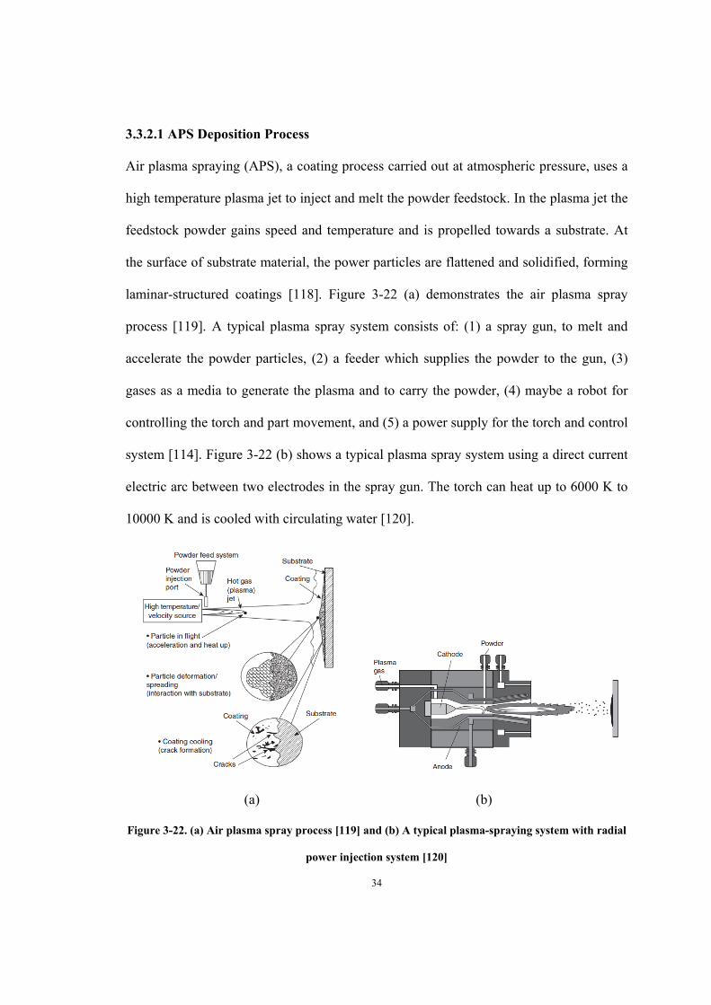
3.3.2.1 APS Deposition Process
Air plasma spraying (APS), a coating process carried out at atmospheric pressure, uses a
high temperature plasma jet to inject and melt the powder feedstock. In the plasma jet the
feedstock powder gains speed and temperature and is propelled towards a substrate. At
the surface of substrate material, the power particles are flattened and solidified, forming
laminar-structured coatings [118]. Figure 3-22 (a) demonstrates the air plasma spray
process [119]. A typical plasma spray system consists of: (1) a spray gun, to melt and
accelerate the powder particles, (2) a feeder which supplies the powder to the gun, (3)
gases as a media to generate the plasma and to carry the powder, (4) maybe a robot for
controlling the torch and part movement, and (5) a power supply for the torch and control
system [114]. Figure 3-22 (b) shows a typical plasma spray system using a direct current
electric arc between two electrodes in the spray gun. The torch can heat up to 6000 K to
10000 K and is cooled with circulating water [120].
(a) (b)
Figure 3-22. (a) Air plasma spray process [119] and (b) A typical plasma-spraying system with radial
power injection system [120]

35
3.3.2.2 Microstructure of APS Coatings
The morphology of APS coatings is characteristically a porous lamellar microstructure
with micro-pores and micro-cracks in the coatings, as shown in Figure 3-23 [121]. The
basic structure of APS coating is built up with pancake-shape splats due to the impact of
molten powder particles [122] (Figure 3-24). The splat morphology can be affected by
surface roughness of the bond coat and substrate orientation. The plasma spraying
parameters can influence the temperature and velocity of particles hence the splat size
and shape. The splats are usually about 1-50 μm thick and 10-50 μm in diameter
[114,123]. Several layers of splats form a horizontal lamella and the boundaries between
lamellae are distinctively visible on the cross sections of the coatings due to the
differences in contrast (darker area usually contains more oxygen).
Figure 3-23. Cross section showing microstructure of lamellar APS coating [121]

36
Figure 3-24. Schematic of typical plasma-sprayed coating [114,123]
In addition to horizontal delamination, vertical microcracks are also present in APS
coatings, a result of the weak adhesion between lamellae and splats and quenching stress
during spraying process [124]. Costil et al. showed that the thermal conductivity of
plasma spraying coatings is affected more by large size horizontal cracks than the vertical
microcracks. Since thermal conductivity depends on the contact between lamellae,
coatings with macro horizontal cracks exhibit low thermal conductivity [115].
The high porosity of APS coatings results from the rapid solidification of lamellae. These
pores and voids, with varying shapes and sizes, are usually found to be oriented parallel
or perpendicular to the coating surface [114]. Splashing that happens during APS
deposition process makes APS coatings more random-shaped. Montavon et al. concluded
that the larger the impinging particles are, the higher the tendency that splashing occurs.
The smaller sized particles are more likely to be vaporized in the plasma flame while the
large size particles are partially melted or unmelted and have a low velocity (higher mass)
for proper spreading to happen, thus unmelted particles can often be observed in the APS
coatings [123]. The presence of large voids can also be explained by poor bonding of
unmelted particles [124].

37
3.3.2.3 Failure of APS TBCs
Under isothermal and cyclic high temperature conditions, APS TBCs usually spall as a
result of the stresses developed in the coatings [117]. The lifetime of TBCs can be
influenced by thermal expansion mismatch between top coat and bond coat, adhesion of
TGO to the bond coat, sintering effect (in increasing elastic modulus), detrimental phase
transformation, corrosion, erosion and residual stresses from deposition process [125].
“A monoclinic phase (m) and an yttrium-rich cubic phase (c) are the room temperature
equilibrium phases for YSZ” [126]. However, a non-equilibrium tetragonal phase (t’) is
developed during the rapid cooling after the APS deposition process; this t’ phase can
decompose into a tetragonal phase (t) (and cubic phase) at elevated temperature. When
being cooled to room temperature, t phase can transform back into m phase, with an
increasing volume of 4-5% [126]. This volume change can greatly affect the durability of
the TBC system and lead to cracking. Helminiak et al. found that high- purity, low-
density APS coatings are more resistant to phase transformation such as t→ m+c as well
as sintering [127]. Also, the thermal exposure temperature affects the stability of t’ phase.
For every YSZ system, there is an upper temperature limit, beyond which t’ will
decompose as shown in Figure 3-25 [128,129].

38
Figure 3-25. ZrO2-YO1.5 phase diagram [128-130]
3.3.3 Nano-Structured TBC Coatings
As traditional APS coatings cannot meet the increasing demand for certain aero-engine
applications (high stress and thermal cycling), nanostructured coatings have been
developed and studied in the last decades [18]. Nanostructured coatings have the
advantages of lower thermal conductivity, higher thermal shock resistance and coefficient
of thermal expansion, excellent mechanical properties and lower cost compared to EB-
PVD coatings [131].

39
Nanostructured TBCs can be generated using agglomerated powders with nanosized
particles inside. When the powders are heated and accelerated in a flame or jet, partial
melting will happen on the surface while the particles inside the powders keep the
original shape. According to Yang et al., after thermal spraying, most of the
agglomerated YSZ powders were partially molten whereas some could be fully molten
[132]. The degree of melting in the agglomerated powders is related to the particle size.
As shown in Figure 3-26, YSZ with an agglomerated powder size of 90 μm only has a
small degree of melting while the small sized powder is fully molten. Since nanostructure
inside the powder is very beneficial to the reduction of thermal conductivity and
increased thermal shock resistance, the agglomerated YSZ powder size needs to be
controlled to prevent complete melting [132]
Figure 3-26. Cross-sections of plasma sprayed agglomerated YSZ powder with an approximate size
of a) 90 μm, b) 50 μm, c) 20 μm [132]
3.3.4 Suspension Plasma Spraying (SPS)
When the powders used in nanostructured thermal spray method have particle sizes of
less than 1 μm, they cannot be injected into the plasma plume, due to nanoparticle’s low
weight and poor ability to flow [133]. This problem can be solved by suspending the fine
particles in a liquid carrier and injecting the liquid suspension into the jet instead of
powder alone. This method is referred to as suspension plasma spraying (SPS) [18].

40
During the ASPS deposition process, the suspension droplets undergo several changes:
aerodynamic breakdown, evaporation of the liquid (carrier), evaporation of the solid
powder material, sintering of fine solids, melting and further sintering into larger
agglomerates, impact with the substrate. These stages are illustrated in Figure 3-27. In
addition, splashing may occur due to liquid impact. Finally solidified nano/micro-sized
crystals form on the substrate [134].
Figure 3-27. Stages that suspension droplets undergo during the plasma spraying [134]
3.3.4.1 Microstructure of SPS Coatings
Coatings obtained using SPS usually exhibit a two-zone microstructure, where the
unmolten, partially sintered nanoparticles are surrounded by lamellar splats formed by
molten and agglomerated fine solids [135], as shown in Figure 3-28 [136]. Porosity can
be observed between lamellae in coatings processed by SPS. Vertical cracks, which were
assumingly caused by the relaxation of thermal stresses, also appear inside lamellae
grains [137].
Small pores between splats are formed due to the weak inter-splat contact [131]. “The
coating porosity is affected by the melting degree of particles” [133]. More fully molten

41
particles can result in a very dense coating. The formation of inter-lamellae cracks/voids
and intra-lamellae cracks can also be attributed to gas entrapment and quenching stresses,
respectively [133]. A wide range of different microstructures can be obtained by varying
the deposition process and spray parameters, such as the initial size of powder, injection
velocity, power loading in the suspension and the temperature of spraying [134,138].
Since the deposition rate of SPS is much lower than that of APS method, it is hard to
obtain thick coatings by SPS method. Therefore SPS coatings usually have a smaller
thickness ranging from 30 to 70 μm [135].
Figure 3-28. Two-zone microstructure of SPS coating [136]
3.3.4.2 Thermal Cycling Behavior of SPS Coatings
Compared to conventional APS coatings, SPS coatings exhibit the following improved
behaviors during thermal exposure:
Higher phase stability during thermal cycles [13]
Lower TGO growth rate with the formation of continuous, uniform, dense, and thin
TGO layers [139]
Reduced formation and growth of spinels at TGO/ top coat and TGO/ bond coat
interface [139]

42
Higher thermal cyclic oxidation resistance [140]
Lower thermal diffusivity/conductivity [141]
Less stress generated from thermal cycling [142]
All these features are desirable for a coating; as a result, nanostructured SPS coatings
have longer lifetimes than conventional APS coatings.
3.3.5 Vertically Cracked (VC) and Columnar Structured Coatings by SPS Method
Lamellar structured SPS coatings are prone to spallation due to thermal stresses arisen
from thermal cycling. Tensile stress develops in ceramic layer during heating because of
the thermal expansion mismatch between underlying metal substrate, bond and ceramic
top coat, whereas compressive stress is seen during cooling. The stresses accumulated in
the coating will lead to crack initiation, growth and buckling. One way to reduce/relax the
stress is to introduce vertical cracks (VC) within the ceramic layer. Figure 3-29 shows the
cross-sectional microstructure of VC ceramic coating [144]. Similar to the columnar
microstructure of EB-PVD coatings, VC coatings reduce the tensile stress by opening up
at high temperature and also yield a lower level of compression during cooling, thus
prolong the life of TBC [19]. The formation of vertically cracked coatings requires both
high substrate temperature and high temperature gradient between surface and impinging
particles [19]. The number of vertical cracks increases with higher plasma spray power
input due to an elevated substrate temperature during spraying. Higher final deposition
temperature also results in longer cracks throughout the coating thickness which are
beneficial to stress relief [143].

43
Figure 3-29. VC YSZ coating (cross section) [144]
In the suspension plasma spraying process, the molten droplets impact the surface of
substrate and form splats. On the surface of the substrate, the formerly deposited layer,
whether solidified or not, can still be melted again by the following layer thus the
bonding between layers can be improved. Due to the tensile stress developed during
deposition (denser coating increases elastic modulus, hence higher thermal stress),
vertical microcracks start to grow in the deposited layer. Microcracks continue to
propagate during the spraying process, helping reduce the stress in the following layers
throughout the coating thickness. However if the coating is deposited at a lower
temperature such as that in conventional SPS process the new layer is not able to re-melt
the former layer, resulting in weak bonding between layers. To relieve the stresses, cracks
grow horizontally between the layers instead of vertically, making APS coating more
prone to spallation during use [143,144,146].

44
3.3.6 Axial Suspension Spraying (ASPS)
In axial suspension spraying (ASPS), a suspension of fine particles in a liquid carrier is
axially injected into the plasma stream, providing more acceleration to suspension [18].
ASPS deposition process, through changing the processing parameters, can produce not
only VC top coats but also columnar structured coatings, as shown in Figure 3-30. The
properties of ASPS coatings are very similar to EB-PVD coatings, with higher bond
strength and strain tolerance but slightly higher thermal conductivity than that of APS
coatings (Table 3-5) [17]. The costs of SPS columnar structured and VC coatings are
much less than that of EB-PVD coatings since plasma spraying is a relatively low-cost
process with high deposition efficiency.
Table 3-5. Summarized properties of APS, ASPS and EB-PVD coatings [17]
Properties APS ASPS EB-PVD
Bond Strength (MPa) 20-40 50-82 65-75
Thermal Conductivity (W/m.K) 0.9-1.5 1-2 1.7-2
Figure 3-30. Cross sectional morphology of columnar coating by ASPS method [17]
45
Although vertically cracked and columnar structured coatings have much longer thermal
cycling lifetime than traditional lamellar structured APS coatings, they may still suffer
from spallation after a long period of thermal exposure. However, the segmentation crack
network can lead to the partial spallation rather than the spallation of the entire ceramic
coating layer [143]. The causes of failure are reported to be similar to those of traditional
APS coatings, such as phase change, growth of spinels between YSZ and TGO, stresses
induced during thermal cycling, coefficient of thermal expansion mismatch, and rumpling
of TGO [147].
3.4 Isothermal Oxidation of TBCs and Microstructure Changes
Some aero and industrial gas turbines are exposed to long term high temperature
oxidation during service. During isothermal exposure, TBC coatings can experience
various microstructural changes, which contribute to the coating failure.
Zhou et al. [22], who conducted isothermal test on APS YSZ + MCrAlY TBC system at
1050C in pure O2 and O2 with 5% water vapor, found that the oxidation rate was very
low in O2 and Al2O3 was the only oxide formed after 400 h of oxidation. However,
chromia, spinels and NiO (CSN) was observed in the TBC in water vapor atmosphere
after 400 h of oxidation. The morphologies of alumina were dense while those of CSN
were porous [22].
Poza et al. [148] have compared the isothermal oxidation behaviors of TBC (APS YSZ +
NiCrAlY) at 950C and 1050C. It is observed that the TBC tested at 1050C had a
higher TGO growth rate than the one tested at 950C. Al2O3 and Cr2O3 were formed after
336 h at 950C, and some delamination at top coat/bond coat interface was clearly visible

46
as shown in Figure 3-31; whereas at 1050°C, NiO and spinels were found inside TGO
after 336 h. The fast growth of spinels and associated volume change had caused
spallation of the top coat, as shown in Figure 3-32 [148].
Figure 3-31. TGO formed in TBC after 336 h of isothermal oxidation at 950C [148]
Figure 3-32. Spallation and cracking at top coat/bond coat interface after 336 h of oxidation at
1050C [148]

47
During isothermal oxidation, the weight of TBC system gradually increases and then
slowly decreases due to partial spallation of top coat. Xu et al. [149] have investigated the
weight change of NiCrAlY bond coats in the isothermal oxidation at 1100C. The weight
changes of TBCs are shown in Figure 3-33. Mixed oxides and spinels were also found in
the TGO layer after 400 h of oxidation [149].
Figure 3-33. Weigh changes of TBCs in a function of oxidation time at 1100C [149]
3.5 Cyclic Oxidation Life of TBCs and Microstructure Changes
Gas turbines are subjected to frequent starts and shut-downs during service, so it is very
important to investigate the cyclic oxidation life of TBCs. A lot of research has been
carried out to predict TBC’s life during high temperature thermal cycling.
Li et al. [150] have investigated the cyclic oxidation behavior of TBC (EB-PVD YSZ top
coat + NiCrAlY bond coat) at 1050C. The as-deposited YSZ top coat contained a
nonequilibrium tetragonal phase t’. Tetragonal phase (t) was the only phase detected in
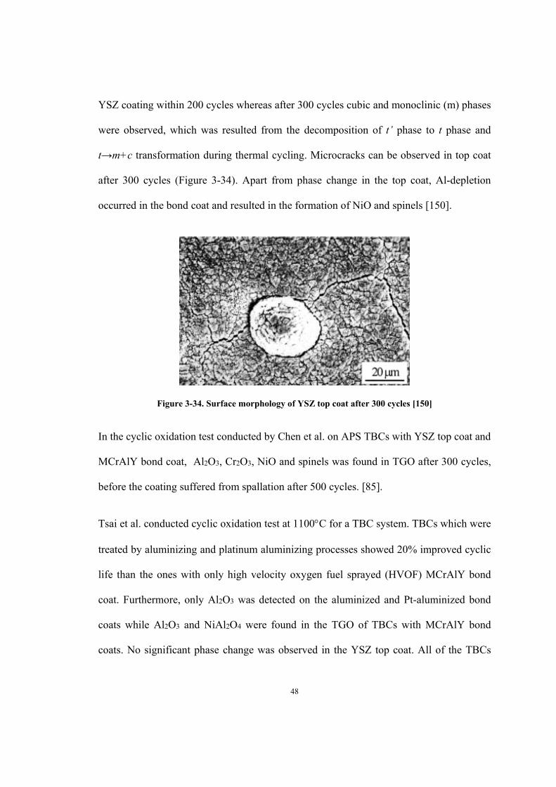
48
YSZ coating within 200 cycles whereas after 300 cycles cubic and monoclinic (m) phases
were observed, which was resulted from the decomposition of t’ phase to t phase and
t→m+c transformation during thermal cycling. Microcracks can be observed in top coat
after 300 cycles (Figure 3-34). Apart from phase change in the top coat, Al-depletion
occurred in the bond coat and resulted in the formation of NiO and spinels [150].
Figure 3-34. Surface morphology of YSZ top coat after 300 cycles [150]
In the cyclic oxidation test conducted by Chen et al. on APS TBCs with YSZ top coat and
MCrAlY bond coat, Al2O3, Cr2O3, NiO and spinels was found in TGO after 300 cycles,
before the coating suffered from spallation after 500 cycles. [85].
Tsai et al. conducted cyclic oxidation test at 1100C for a TBC system. TBCs which were
treated by aluminizing and platinum aluminizing processes showed 20% improved cyclic
life than the ones with only high velocity oxygen fuel sprayed (HVOF) MCrAlY bond
coat. Furthermore, only Al2O3 was detected on the aluminized and Pt-aluminized bond
coats while Al2O3 and NiAl2O4 were found in the TGO of TBCs with MCrAlY bond
coats. No significant phase change was observed in the YSZ top coat. All of the TBCs

49
had a lifetime around 200 hrs, before spallation occurred to the top coatings, as shown in
Figure 3-35 [151].
Figure 3-35. Weight changes of TBCs with different bond coats as a function of cyclic oxidation life
[151]

50
4 Chapter: Materials and Experimental Procedures
4.1 Substrate Materials
Two substrate materials, IN738LC and CMSX-4, were used in this study. IN738LC was
cast by Sophisticated Alloy, Inc. and CMSX-4 by Howmet International. Their
thermophysical properties and nominal chemical compositions are listed in Table 4-1 and
Table 4-2.
Table 4-1. Experimental data for thermophysical properties of IN738 and CMSX-4 (927-1127C)
[152]
Thermal capacity Cp
(J K-1 Kg-1)
Density ρ
(kg m-3)
Thermal
diffusivity a
(x106m2s-1)
Thermal conductivity k
(W m-1 K-1)
IN738 675-925 7840-7702 4.70-4.87 24.9
CMSX-4 650-925 8283-8193 4.7-5.1 21.9-24.4
Table 4-2. Chemical composition of the substrate materials
Ni Cr Co Mo W Ta Nb Al Ti Re C
IN738LC Bal 16 8.5 1.7 2.6 1.7 0.9 3.4 3.4 - 0.11
CMSX-4 Bal 6.5 9 0.6 6 6.5 - 5.6 1 3 -
4.1.1 IN738LC
IN738LC, which contains a large amount of refractory elements such as tungsten,
molybdenum, tantalum and niobium (as highlighted in Table 4.2), is a precipitation
strengthened nickel based superalloy [153]. The two-phase γ/γ’ microstructure of as-

51
received IN738LC substrate is shown in Figure 4-1. IN738LC is widely used to
manufacture the hot section components of aero-engines and gas turbines due to its good
phase stability, excellent strength and high corrosion resistance at elevated temperature
[32]. However IN738LC usually shows very low ductility. Balikci et al. have reported
that the ductility and fracture behavior as well as yield strength and tensile strength of
IN738LC are affected by the microstructures and sizes of precipitates (primarily γ’) [154].
For instance, microstructure with finer precipitate sizes usually exhibits lower ductility
while coarser precipitates are linked to better ductility [155-156].
Figure 4-1: γ/γ’ structure of IN738LC Superalloy
4.1.2 CMSX -4
CMSX-4 is a second generation nickel based single crystal superalloy; as shown in
Figure 4-2, it is a two-phase material with cubical intermetallic γ’ (Ni3Al) phase
coherently embedded in γ nickel solid solution matrix [157,158]. CMSX-4 exhibits
excellent performance at high temperature because of the large volume fraction of the
strengthening phase γ’ [159]. The γ/γ’ structure also provides good ductility and strength
at elevated temperature which make CMSX-4 a widely used material for blade

52
applications in land-base gas turbines [160]. Adding refractory elements such as
tantalum, tungsten and rhenium improves mechanical properties at high temperature, but
consequently reduces the proportion of Cr, which is beneficial for oxidation resistance.
Therefore, a CMSX-4 substrate is usually coated with platinum aluminide to protect it
from high temperature oxidation [161].
During high temperature exposure, coalescence of γ’ precipitates and thickening of γ-
phase channels would occur with increasing time and temperature, leading to rafting [33].
As the strength of γ’ phase (an intermetallic compound) increases with temperature, the
decrease in yield strength of matrix γ due to high temperature can be compensated by the
increasing strength of γ’ precipitates. Thus CMSX-4 exhibits a stable behavior in strength
between room temperature to approximately 900C. After 900C, γ’ phase starts to
dissolve, which leads to a rapid loss of strength [160] but an increase of ductility, a
classical behavior of this kind of precipitation hardened high temperature alloy [162].
Figure 4-2. γ/γ’ structure of CMSX-4 superalloy

53
According to the steady-state scale morphology, when the concentration of Cr is higher
than 15% and that of Al is higher than 3%, the oxide scale formed usually mainly
contains Al2O3 [163]. The Cr/Al ratio in IN738LC is 4.7 compared to 1.25 in CMSX-4
[164]. The different concentrations of Al and Cr affect the oxides formed during thermal
cycling.
4.2 Coating Processes
The samples were disk-shaped with a diameter of about 19 mm and a thickness of 5 mm.
The top YSZ coatings had an average thickness of 200 μm. The PtAl bond was applied
by Chromalloy Inc. using standard process involving Pt plating, pack cementation and
diffusion heat treatment. The columnar and VC 8YSZ coatings were applied using the
Axial III™ plasma torch with a modified injector for suspension atomization and the
NanoFeed™ suspension feeder (Northwest Mettech Corp., North Vancouver, Canada).
The Axial III™ injects the atomized suspension feedstock axially to the direction of spray
into the central core of the plasma. Axial injection overcomes the injection difficulties
that arise when attempting to penetrate the plasma radially with fine particles or droplets.
The NanoFeed is designed to feed submicron suspensions using mass flow control of
both suspension and atomizing gas to provide uniform atomizing dynamics at the
injector. An overview of the ASPS process is shown in Figure 4-3. The powder used was
a customized 8YSZ (partially yttria stabilized zirconia with 8 wt% of yttria) with
submicron powder sizes. After suspending the fine powders in ethanol liquid, the
suspension feedstock was fed by Mettech Nanofeed 350 Suspension feeder to the injector
with stable flow rate and injection pressure for the axial injection plasma spraying
performed by Axial III™ Torch.

54
Figure 4-3. ASPS deposition process [17]
4.3 Sample Preparation Procedures
Before oxidation test, the as-received samples were heat-treated in C700 Oxy-Gon
Vaccum Furnace (Oxy-Gon Industries, NH, USA) at 1080C for four hours. The vacuum
level was 10-4-10-5 torr. After the pre-oxidation treatment, the samples were cut using a
Buehler Isomet 2000 precision saw equipped with a Beta Diamond wafering blade at a
rotating speed of 500 rpm and a load of 250 g. After sectioning, all samples were
ultrasonically cleaned in alcohol for 10 mins. The sectioned samples were then mounted
using a Streuers LaboPress 3 with Buehler PhenoCure 677 and Transoptic powders.
Grinding and polishing were completed by using Buehler Ecomet 4 automatic
grinding/polishing machine with an Automet 2 power head. Buehler-Met II silicon
carbide papers of 180- , 240-, 320-, 400-, 600-, 800-, and 1200-grit sizes were used for
grinding. Samples were subsequently polished using 1μm and 3μm diamond abrasives.

55
Final polishing was performed with MasterMet colloidal silica polishing suspension and
distilled water. Samples were ultrasonically cleaned in UltraMet 2 Sonic Cleaning
Solution before and after each polishing section. The equipment used in sample
preparation is shown in Figure 4-4.
(a) Buehler Isomet 2000 precision saw
(b) Streuers LaboPress 3 mounting machine

56
(c) Buehler Ecomet 4 automatic grinding/polishing machine with Automet 2 power head
Figure 4-4. Equipment used in sample preparation
4.4 Isothermal Oxidation Test
The isothermal oxidation test was conducted at 1080°C for up to 1000 hours, using STT-
1600C-4-12 high temperature tube furnace (Sentro Tech Corp., USA), as shown in Figure
4-5. The temperature of 1080˚C was chosen as other parallel tests (in our research group)
were being conducted at the same temperature. Visual inspection was performed after
every 100 hours. Samples were withdrawn from isothermal oxidation test once the failure
criterion, i.e. more than 30% spallation of the top coatings, was reached. The top coatings
usually spall as a large piece of more than 30% of the coating surface area. Thus, the

57
failure criterion of 30% spallation seemed to be indicative of TBC failure. Details of
samples used in the isothermal oxidation test are listed in Table 4-3.
Figure 4-5. STT-1600C-4-12 high temperature tube furnace used in isothermal oxidation test

58
Table 4-3. Samples used in isothermal oxidation test
Group Number Material Composition
Appearance before
Isothermal Oxidation Test
Oxidation
Test Sample
IDs
1
IN738LC with PtAl +
columnar 8YSZ
Iso#1
2
IN738LC with PtAl +
VC 8YSZ
Iso#2
3
CMSX-4 with PtAl +
columnar 8YSZ
Iso#3
4
CMSX-4 with PtAl + VC
8YSZ
Iso#4

59
4.5 Cyclic Oxidation Test
The cyclic oxidation test was conducted in air using a CM furnace (Rapid Temp Furnace
supplied by Bloom Field, N.J., USA) as shown in Figure 4-6. In order to study the cyclic
oxidation behavior of TBCs experienced by aero-engines, a one-hour cycle was chosen to
simulate the frequent starts and stops. Each cycle consisted of heating to 1080°C (about
10 min.) and holding for 30 min. and then fan-cooling for 20 min (to 300˚C). Visual
inspections were performed after every 100 cycles. Samples were withdrawn from test
once the failure criterion, i.e. more than 30% spallation of the top coatings, was reached.
Information of samples subjected to cyclic oxidation test is shown in Table 4-4.
Figure 4-6. CM Rapid Temp Furnace used in cyclic oxidation test

60
Table 4-4. Samples used in cyclic oxidation test
Group Number Material Composition
Appearance before Cyclic
Oxidation Test
Sample
IDs
1
IN738LC with PtAl +
columnar 8YSZ
Cyc#1
2
IN738LC with PtAl +
VC 8YSZ
Cyc#2
3
CMSX-4 with PtAl +
columnar 8YSZ
Cyc#3
4
CMSX-4 with PtAl +
VC 8YSZ
Cyc#4
4.6 Scanning Electron Microscopy (SEM) and Energy Dispersive Spectrum
(EDS) Analysis
Microscopic evaluation was carried out with two individual scanning electron microscope
(SEM) models. Most of the SEM and EDS analysis was performed on a Philips XL30S
Schottky-based field emission gun (FEG) SEM coupled with a Phoenix EDS detector
system (Figure 4-7). The rest of SEM and EDS analysis was conducted by using VegaII-
XMU SEM (Tescan, Neitherland) and INCA x-act EDS system (Oxford, England) as

61
shown in Figure 4-8. EDS analysis can only provide a qualitative indication of elements
at a certain area or point, but is not accurate enough to identity the stoichiometric ratio of
elements in various phases. Microstructural constituents were identified by combining the
results from X-ray diffraction and EDS analysis.
Figure 4-7. Philips XL30S FEG SEM

62
Figure 4-8. VegaII-XMU SEM
4.7 X-ray Diffraction Analysis (XRD)
The XRD analysis was performed using a Bruker AXS D8 Discover diffractometer,
shown in Figure 4-9, controlled with General Area Detector Diffractometer Software
(GADDS). The samples were scanned from 25-100° (of 2θ angle) with a step size of
0.02/step (1S).

63
Figure 4-9. Bruker AXS D8 Discover Diffractometer for XRD analysis

64
5 Chapter: Microstructure and Composition of As-Coated Samples
The surface morphologies of the columnar structured and VC YSZ coatings before
oxidation tests are shown in Figure 5-1. The columnar YSZ coating has a “broccoli-like”
feature with a few long surface cracks and visible surface pores (Figure 5-1 (a) and (b))
while VC coating has smoother and denser surface but numerous shorter, connected
cracks (Figure 5-1 (c) and (d)). XRD analysis was performed on the top surfaces of
samples Cyc#1 to 4 and the results are shown in Figure 5-3. Traces of (Ni, Pt)Al (β phase
from the bond coat) and γ’-Ni3Al (strengthening phase in IN738LC and CMSX 4) phases
are present in all samples, in addition to ZrO2, a main phase in YSZ. The cross-sectional
microstructures of columnar and VC TBC are shown in Figure 5-2. Similar to that seen
on the surface, columnar coatings have a rougher surface with more pores towards the
top. And for VC coatings, most of the vertical cracks extend to about half of the YSZ
total coating thickness. In the original test plan, a conventional plasma sprayed YSZ top
coat was also included. However, the YSZ sprayed on PtAl bond coat immediately
spalled off after spraying. As such this set of samples could not be included in this study.

65
(a) (b)
(c) (d)
Figure 5-1. Top surface morphologies of columnar (a and b) and VC coatings (c and d)
Figure 5-2. Cross-sections of columnar structured and VC TBC coatings

66
(a) IN738LC with PtAl + columnar 8YSZ
(b) IN738LC with PtAl + VC 8YSZ

67
(c) CMSX-4 with PtAl + columnar 8YSZ
(d) CMSX-4 with PtAl + VC 8YSZ
Figure 5-3. X-ray diffraction pattern from coating top surface before oxidation test

68
Morphologies of PtAl bond coat and IN738LC/CMSX-4 substrate are shown in Figure 5-
4. A two-layered bond coat was presented on the IN738LC substrate whereas a three-
layer bond coat was seen on CMSX-4 substrate. The chemical compositions of different
bond coat layers and substrate (close to and far from bond coat) were measured by EDS
analysis, as listed in Table 5-1. From the table it is obvious that the bond coat layer 1 on
CMSX-4 contained more Pt and Al, while much more Cr and refractory elements Ti, Ta
and W were detected in the bond coat layer 1 on IN738LC. The difference in Pt
concentrations resulted from the separation of bond coat layer into layer 1 (Pt rich) and
layer 2 (Pt lean) on the surface of CMSX-4 substrate (Figure 5-4 (b), layer 1 and layer 2).
Elements from the base metals, such as Ni, Cr, Co, Ta, Ti, W, were found in Layer 2 in
Figure 5-4 (a) and layer 3 in Figure 5-4 (b)) due to diffusion. The EDS analysis also
revealed that there were more Ta and W (less Cr) in layer 3 of CMSX-4 While more Cr
and Ti (and some W) were found in bond coat layer 2 on IN738LC, illustrating the
influence of base metal composition on coating microstructure.

69
(a)
(b)
Figure 5-4. PtAl bond coat with IN738 (a) and CMSX-4 (b) substrate

70
Table 5-1. Chemical compositions of PtAl bond coat (layers and substrate near the bond coat) (wt %)
measured by EDS
PtAl
+
IN738LC
wt % Pt Al Ni Cr Co Ta Ti W Si O
Layer 1 13.25 17.05 55.16 6.48 6.21 0.30 1.55 - - -
Layer 2 - 7.24 37.11 24.34 8.26 9.57 6.03 7.45 - -
Area 1 - 4.02 60.21 18.06 8.18 2.01 3.78 - - -
Area 2 - 2.95 61.71 16.44 9.11 2.04 3.72 3.90 0.12 -
PtAl
+
CMSX-4
Layer 1 24.33 20.79 42.04 2.63 5.35 0.68 - 2.17 - 2.02
Layer 2 10.12 20.88 53.69 3.05 7.12 2.17 - 2.96 - -
Layer 3 - 12.85 45.79 8.40 9.89 8.76 1.21 13.09 - -
Area 1 - 6.27 62.70 7.07 9.85 5.84 1.05 7.22 - -
Area 2 - 5.69 63.36 6.67 10.61 5.66 - 6.67 - -
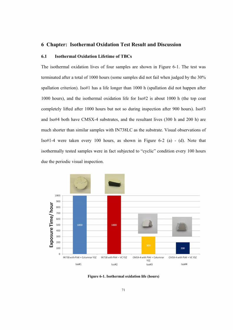
71
6 Chapter: Isothermal Oxidation Test Result and Discussion
6.1 Isothermal Oxidation Lifetime of TBCs
The isothermal oxidation lives of four samples are shown in Figure 6-1. The test was
terminated after a total of 1000 hours (some samples did not fail when judged by the 30%
spallation criterion). Iso#1 has a life longer than 1000 h (spallation did not happen after
1000 hours), and the isothermal oxidation life for Iso#2 is about 1000 h (the top coat
completely lifted after 1000 hours but not so during inspection after 900 hours). Iso#3
and Iso#4 both have CMSX-4 substrates, and the resultant lives (300 h and 200 h) are
much shorter than similar samples with IN738LC as the substrate. Visual observations of
Iso#1-4 were taken every 100 hours, as shown in Figure 6-2 (a) - (d). Note that
isothermally tested samples were in fact subjected to “cyclic” condition every 100 hours
due the periodic visual inspection.
Figure 6-1. Isothermal oxidation life (hours)

72
100 h 200h 300 h 400 h 500 h
600 h 700 h 800 h 900 h 1000 h
(a) Iso#1
100 h 200 h 300 h 400 h 500 h
600 h 700 h 800 h 900 h 1000 h
(b) Iso#2

73
100 h 200 h 300 h
(c) Iso#3
100 h 200 h
(d) Iso#4
Figure 6-2. Visual observations of Iso#1-4 (every 100 h)
6.2 Microstructure Analysis of Isothermally Oxidized Samples
6.2.1 Samples with PtAl Bond Coat-Columnar Structured YSZ Top Coat
The oxidized samples were analyzed by SEM and EDS on several locations including (a)
top coating surface, (b) coating backside (the inside surface of spalled coating), (c)
exposed bond coat/substrate surface and finally (d) the cross section. From the results
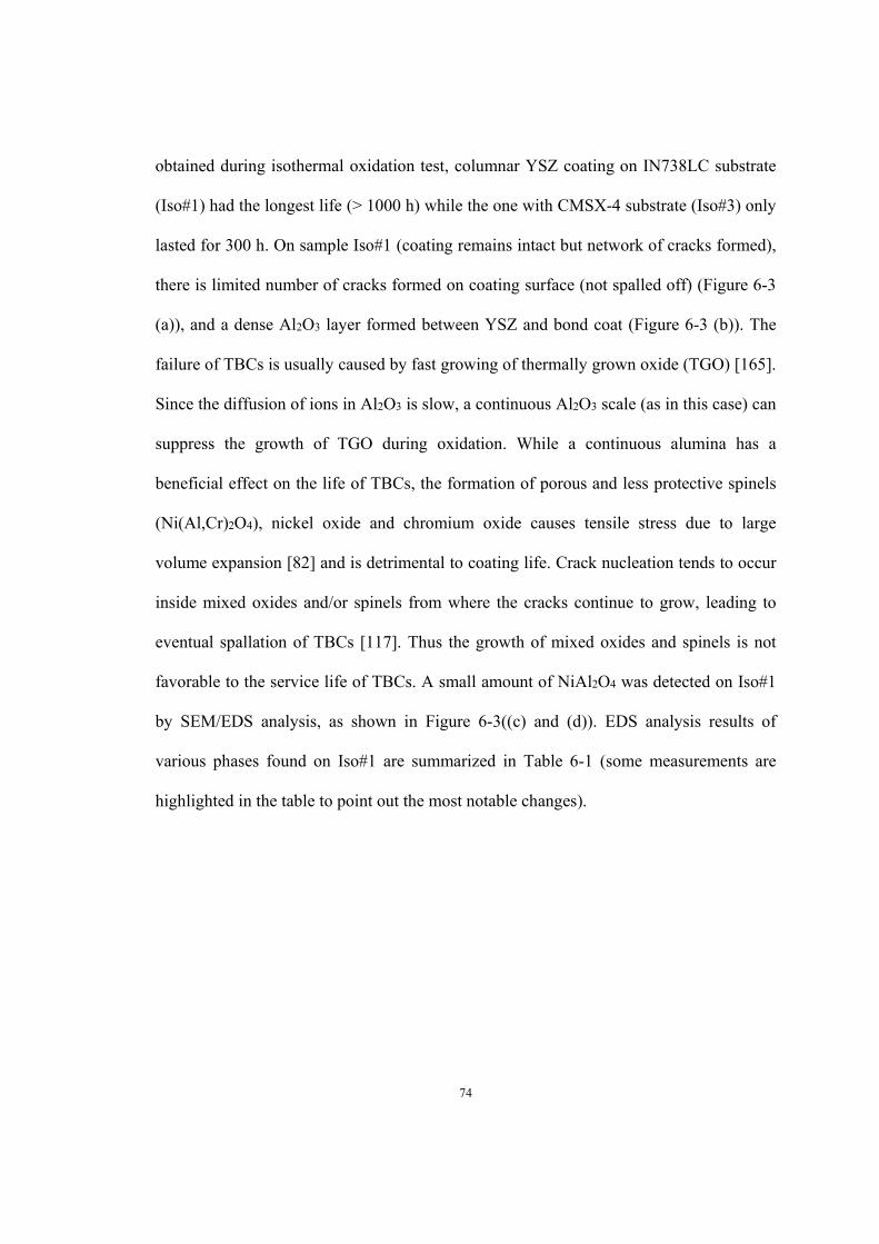
74
obtained during isothermal oxidation test, columnar YSZ coating on IN738LC substrate
(Iso#1) had the longest life (> 1000 h) while the one with CMSX-4 substrate (Iso#3) only
lasted for 300 h. On sample Iso#1 (coating remains intact but network of cracks formed),
there is limited number of cracks formed on coating surface (not spalled off) (Figure 6-3
(a)), and a dense Al2O3 layer formed between YSZ and bond coat (Figure 6-3 (b)). The
failure of TBCs is usually caused by fast growing of thermally grown oxide (TGO) [165].
Since the diffusion of ions in Al2O3 is slow, a continuous Al2O3 scale (as in this case) can
suppress the growth of TGO during oxidation. While a continuous alumina has a
beneficial effect on the life of TBCs, the formation of porous and less protective spinels
(Ni(Al,Cr)2O4), nickel oxide and chromium oxide causes tensile stress due to large
volume expansion [82] and is detrimental to coating life. Crack nucleation tends to occur
inside mixed oxides and/or spinels from where the cracks continue to grow, leading to
eventual spallation of TBCs [117]. Thus the growth of mixed oxides and spinels is not
favorable to the service life of TBCs. A small amount of NiAl2O4 was detected on Iso#1
by SEM/EDS analysis, as shown in Figure 6-3((c) and (d)). EDS analysis results of
various phases found on Iso#1 are summarized in Table 6-1 (some measurements are
highlighted in the table to point out the most notable changes).

75
(a) Top coat surface (b) Exposed substrate/bond coat
(c) Cross section (d) Cross section
Figure 6-3. Microstructures of Sample Iso#1 (IN738LC with PtAl + columnar YSZ) after oxidation
test

76
Table 6-1. EDS analysis results of Iso#1 (wt % and at %)
Element
O*
Ni
Al
Ta
Zr
Ti
Cr
Co
Si
Al2O3(on
bond
coat/substrate
surface)
Wt%
41.83
1.22
41.84
1.7
2.27
6.88
4.26
-
-
At%
58.8
0.47
34.88
0.21
0.56
3.23
1.84
-
-
NiAl2O4
(cross section)
Wt%
36.73
24
31.13
-
-
1.31
2.88
3.19
0.77
At%
57.07
10.16
28.68
-
-
0.68
1.38
1.34
0.68
*note that semi-quantitative EDS analysis generates larger error on the analysis of non-metallic elements.
For sample Iso#3, a network of cracks was well developed on the YSZ coating surface
(Figure 6-4 (a)). On the spalled YSZ coating backside shown in Figure 6-4 (b), there is a
good coverage of alumina (indicating the failure within TGO), with occasional bare
patches of YSZ (failure from YSZ separating from TGO). However, very little alumina
was found on the exposed bond coat/substrate surface, as shown in Figure 6-4 (c). This
observation suggests that the failure/spallation site is mostly between Al2O3 and bond
coat. Further examination of the cross section of sample Iso#3 (Figure 6-4 (g) and (h))
confirms that the coating spallation had occurred at the TGO and bond coat interface
during the isothermal test. W-rich and Ta-rich precipitants are observed on the exposed
bond coat/substrate surface and inside the remaining TGO layer, as shown in Figure 6-4
(d) and (e). The elevated Ta and W in the CMSX-4 coating system may have weakened
the TGO adhesion (with YSZ), leading to premature failure. Mixed oxides or spinels
were not found during SEM/EDS analysis (probably due to the limited exposure time

77
since mixed oxides are mostly formed as the oxidation process progresses to later stage).
XRD analysis on the backside (the side facing the substrate) of the spalled 8YSZ coating
piece and bond coat/substrate surface further confirmed that only Al2O3 and YSZ existed
(Figure 6-5 and Figure 6-6). EDS analysis results of Iso#3 are summarized in Table 6-2.
(a) YSZ top coat surface (b) Back side of the spalled YSZ
(c) Exposed bond coat/substrate (d) Exposed bond coat/substrate

78
(e) TGO layer on (d) (f) Cross section
(g) Cross section (h) Cross section
Figure 6-4. Microstructures of Sample Iso#3 (CMSX-4 with PtAl + columnar YSZ) after isothermal
oxidation test
Table 6-2. EDS analysis results of Iso#3 (wt% and at%)
Element O Al Hf Y Zr
Al2O3
(YSZ backside) wt% 45.08 54.92 - - -
at% 58.06 41.94 - - -
ZrO2
(YSZ backside)
wt% 28.11 1.05 1.39 9.54 59.9
at% 68.43 1.52 0.3 4.18 25.57
2 µm
50 µm

79
Figure 6-5. X-ray diffraction pattern from the backside of the spalled YSZ (Iso#3, CMSX-4 with PtAl
+ columnar YSZ)
Figure 6-6. X-ray diffraction pattern of bond coat/substrate (Iso#3, CMSX-4 with PtAl + columnar
YSZ)
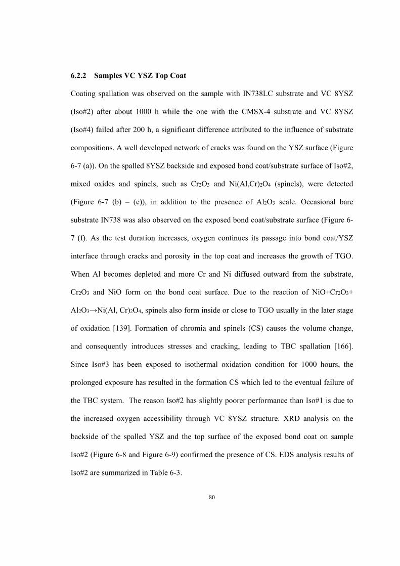
80
6.2.2 Samples VC YSZ Top Coat
Coating spallation was observed on the sample with IN738LC substrate and VC 8YSZ
(Iso#2) after about 1000 h while the one with the CMSX-4 substrate and VC 8YSZ
(Iso#4) failed after 200 h, a significant difference attributed to the influence of substrate
compositions. A well developed network of cracks was found on the YSZ surface (Figure
6-7 (a)). On the spalled 8YSZ backside and exposed bond coat/substrate surface of Iso#2,
mixed oxides and spinels, such as Cr2O3 and Ni(Al,Cr)2O4 (spinels), were detected
(Figure 6-7 (b) – (e)), in addition to the presence of Al2O3 scale. Occasional bare
substrate IN738 was also observed on the exposed bond coat/substrate surface (Figure 6-
7 (f). As the test duration increases, oxygen continues its passage into bond coat/YSZ
interface through cracks and porosity in the top coat and increases the growth of TGO.
When Al becomes depleted and more Cr and Ni diffused outward from the substrate,
Cr2O3 and NiO form on the bond coat surface. Due to the reaction of NiO+Cr2O3+
Al2O3→Ni(Al, Cr)2O4, spinels also form inside or close to TGO usually in the later stage
of oxidation [139]. Formation of chromia and spinels (CS) causes the volume change,
and consequently introduces stresses and cracking, leading to TBC spallation [166].
Since Iso#3 has been exposed to isothermal oxidation condition for 1000 hours, the
prolonged exposure has resulted in the formation CS which led to the eventual failure of
the TBC system. The reason Iso#2 has slightly poorer performance than Iso#1 is due to
the increased oxygen accessibility through VC 8YSZ structure. XRD analysis on the
backside of the spalled YSZ and the top surface of the exposed bond coat on sample
Iso#2 (Figure 6-8 and Figure 6-9) confirmed the presence of CS. EDS analysis results of
Iso#2 are summarized in Table 6-3.

81
(a) Top of YSZ (b) Backside of spalled YSZ
(c) Backside of spalled YSZ (d) Exposed bond coat/substrate
(e) Exposed bond coat/substrate (f) Exposed bond coat/substrate
Figure 6-7. Microstructures of sample Iso#2 (IN738LC with PtAl + VC YSZ) after oxidation test
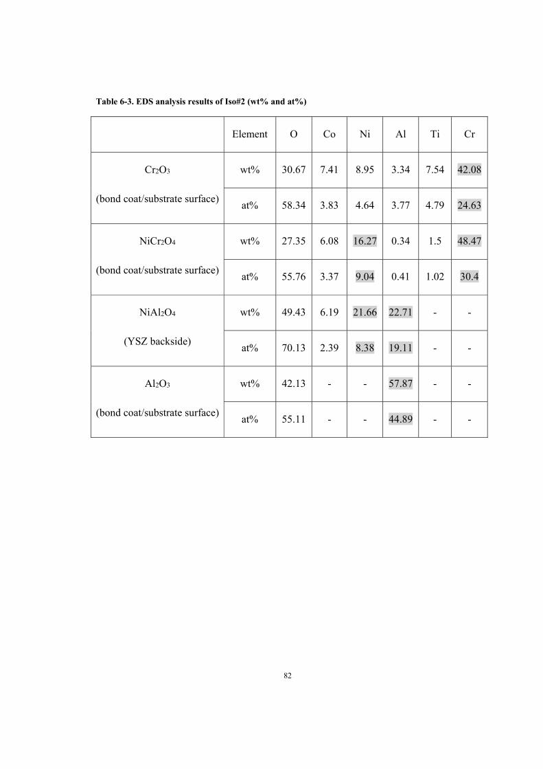
82
Table 6-3. EDS analysis results of Iso#2 (wt% and at%)
Element O Co Ni Al Ti Cr
Cr2O3
(bond coat/substrate surface)
wt% 30.67 7.41 8.95 3.34 7.54 42.08
at% 58.34 3.83 4.64 3.77 4.79 24.63
NiCr2O4
(bond coat/substrate surface)
wt% 27.35 6.08 16.27 0.34 1.5 48.47
at% 55.76 3.37 9.04 0.41 1.02 30.4
NiAl2O4
(YSZ backside)
wt% 49.43 6.19 21.66 22.71 - -
at% 70.13 2.39 8.38 19.11 - -
Al2O3
(bond coat/substrate surface)
wt% 42.13 - - 57.87 - -
at% 55.11 - - 44.89 - -

83
Figure 6-8. X-ray diffraction pattern from the backside of spalled YSZ (sample Iso#2, IN738LC with
PtAl + VC YSZ)
Figure 6-9. X-ray diffraction pattern from the exposed bond coat/substrate surface (sample Iso#2,
IN738LC with PtAl + VC YSZ)

84
From the EDS analysis of the exposed bond coating/substrate surface of Iso#4 after top
coat spallation, the majority of the exposed surface has bond coat composition and there
was occasional Al2O3 remaining on the surface. And there was no evidence of CS (Figure
6-10). XRD analysis, Figure 6-11, confirmed that no CS formed. The short oxidation
duration of sample Iso#4 (200 h), before final failure, might not be sufficient for the
formation of CS (usually due to the Al depletion and outward diffusion of Cr and Ni).
The resulted morphology of exposed bond coat/substrate surface (due to top coat
spallation) (Figure 6-10 (a) and (b)) was very similar to that of Iso#3 (Figure 6-4 (c)),
indicating the spallation occurred at TGO/bond coat interface. It is important to know that
although the premature failure of sample Iso#4 was not as a direct result of CS formation,
the presence of W and Ta containing phases in the TGO (Figure 6-10 (a)-(c)) provided
indication that outward diffusion of Ta and W had taken place, leading to void
(Kirkendall effect) formation at the TGO/bond interface. This may be reason for the
early spallation of sample Iso#4. EDS analysis results of Iso#4 are shown in Table 6-4.

85
(a) Bond coat/substrate surface (b) Bond coat/substrate surface
(c) Cross section where some YSZ still remained (d) Cross section
Figure 6-10. Microstructures of Iso#4 (CMSX-4 with PtAl + VC YSZ) after oxidation test
Table 6-4. EDS analysis results of Iso#4 (wt% and at%)
Al2O3
Element O Al
wt% 38.8 61.2
at% 51.67 48.33

86
Figure 6-11. X-ray diffraction pattern from the exposed bond/coat substrate surface (sample Iso#4,
CMSX-4 with PtAl + VC YSZ)
6.3 Discussion
As clearly shown in Figure 6-1, the TBC systems with IN738LC substrate had much
longer isothermal oxidation lifetimes than those with CMSX-4 substrate. Sample Iso#1
and Iso#2 (IN738LC substrate) had a lifetime of ≥1000 h while Iso#3 and Iso#4 failed
prematurely after 300 h and 200 h, respectively.
For the TBCs with IN738LC substrate, the oxides formed in sample Iso#1 are different
than that in Iso#2. Al2O3 and a small amount of NiAl2O4 were observed in Iso#1 after
oxidation. However, a large amount of chromia and Ni(Al,Cr)2O4 was observed in
sample Iso#2, both on exposed bond coating/substrate surface and the backside of spalled
YSZ coating piece. After 1000 h exposure, spallation did not occur to sample Iso#1

87
(columnar YSZ); whereas sample Iso#2 (with VC YSZ), failed after 1000 h. A dense
Al2O3 oxide layer and the lack of CS on sample Iso#1 suggest the protective nature of
columnar structured YSZ top coat, leading to lower rate of oxygen penetration than that
with VC top coat (Iso#2). Although VC top coat has fewer pores and voids than a
columnar structured top coat, the through thickness cracks make it easier for oxygen to
travel through and reach the bond coat, facilitating the continuous formation of TGO and
CS once Al is depleted (from both inward diffusion and TGO formation).
Samples Iso#3 and Iso#4 with CMSX-4 substrate had much shorter lives than the ones
with IN738LC substrate. The fact that no oxide other than alumina was found in Iso#3
and Iso#4 alluded that spinel phases only grow after certain duration in oxidizing
environment when Al is sufficiently depleted. Formation of spinel phases was not likely
responsible for the TBC failure of these two samples. However, there are a number of
high contrast particles observed within the TGO on both samples after oxidation, as
shown in Figure 6-4 (d)-(e), Figure 6-10 (a)-(c). They were identified as precipitates of
heavy alloying elements (W and Ta) from CMSX-4, due to outward diffusion during
isothermal exposure. When the fluxes from two sides of a diffusion couple are not equal,
a vacancy flux is developed to balance the interdiffusion, leading to the formation of
pores and voids, often at the interface [167]. Since there were far more outward diffusion
(W, Ta, Cr, Ni for example), from substrate to TGO, occurred than inward diffusion
(oxygen and Al), from TGO to bond coat/substrate, according to Kirkendall effect, the
large amount of outward diffusion cannot be compensated by the fewer amount of inward
diffusion, voids formed along the interface [168]. Indeed, as seen in Figure 6-10 (c), there
were voids formed at the interface of TGO and bond coat. Similar to that observed with

88
IN738LC substrate, the columnar 8 YSZ top coat provided reduced oxygen permeability
than VC top coat, as such, longer isothermal life was observed in sample Iso#3.
Furthermore, failure location/mode of samples with CMSX-4 substrate was different
from those with IN738LC substrate. In the cases of Iso#1 and Iso#2 (IN738LC), the YSZ
top coat was separated from within the TGO, as most of the exposed bond coat/substrate
and spalled YSZ were covered with Al2O3 layer (Figure 6-3 and Figure 6-7). However,
from the observation of samples Iso#3 and Iso#4, the YSZ top coating spalled at the
interface between TGO and bond coat/substrate. As shown in Figure 6-4 (g)-(h), the top
coat along with Al2O3 (TGO) was completely separated from the bond coat/substrate (the
dark bakelite material between them was introduced during sample preparation).
Similarly, for Iso#4, as shown in Figure 6-10 (b), only very scant Al2O3 remained on the
bond coat/substrate surface after top coat spallation. Also, from the SEM image in Figure
6-10 (c), it is clear that most of the voids are present at the interface between TGO and
bond coat/substrate. This provides an indication that the formation of voids contributed to
the early failure of the TBCs with CMSX-4 substrate; and the outward diffusion of
refractory elements (W, Ta and maybe Re) has caused the development of voids.

89
6.4 Summary of Isothermal Test Results
The TBC system with IN738LC substrate exhibited longer isothermal oxidation life than
the TBC system with CMSX-4 substrate. Sufficient evidence suggests that outward
diffusion of refractory elements in CMSX-4 into TGO was responsible for short
isothermal oxidation life as voids formed between TGO and bond coat/substrate interface
due to diffusion. Additionally, columnar YSZ top coat provided better protection to the
bond coating and substrate, delaying the coating failure in both systems with IN738LC
and CMSX-4 substrate.

90
7 Chapter: Cyclic oxidation test results
7.1 Cyclic Oxidation Lifetime of TBCs
The cyclic oxidation lives of four different samples are represented in Figure 7-1. All
samples failed within 1000 cycles. Cyc#1 and Cyc#2 (both with IN738LC substrate)
spalled after 365 and 300 cycles, respectively; whereas samples with CMSX-4 substrate,
Cyc#3 and Cyc#4, experienced 500 and 1000 cycles, respectively, before failure. Visual
observations were carried out every 100 cycles; the images are presented in Figure 7-2.
Figure 7-1. Cyclic oxidation life (in terms of number of cycles)

91
100 cycles 200 cycles 300 cycles 365 cycles
(a) Cyc#1
100 cycles 200 cycles 300 cycles
(b) Cyc#2
100 cycles 200 cycles 300 cycles 400 cycles 500 cycles
(c) Cyc#3

92
100 cycles 200 cycles 300 cycles 400 cycles 500 cycles
600 cycles 700 cycles 800 cycles 900 cycles 1000 cycles
(d) Cyc#4
Figure 7-2. Visual observations of Cyc#1-4 (images taken every 100 cycles)
7.2 Microstructure Analysis of Cyclic Oxidation Tested Samples
7.2.1 Samples with PtAl Bond Coat and Columnar YSZ Top Coat
During the cyclic oxidation test, sample Cyc#1 (IN738LC with PtAl + columnar YSZ)
failed after 365 cycles while sample Cyc#3 (CMSX-4 with PtAl + columnar YSZ) was
found to exceed the spallation limit after 500 cycles. SEM/EDS analysis of sample Cyc#1
reveals both alumina and NiAl2O4 on the backside of spalled YSZ coating and bond
coat/substrate surface, as shown in Figure 7-3 (a)-(c). From the cross sectional view of
the microstructure, it is clear that YSZ has completely separated from the TGO and also
vertical cracks have progressed to the interface between YSZ and TGO (Figure 7-3 (d),
(e)). EDS analysis results of Cyc#1 are summarized in Table 7-1.

93
XRD analysis was carried out on both the backside of the spalled YSZ and the top
surface of exposed bond coating/substrate; the diffraction spectra are given in Figure 7-4
and Figure 7-5. They further confirm that spinel (NiAl2O4) and alumina (Al2O3) are
attached to the spalled YSZ, suggesting that spallation occurred within the TGO where
sufficient amount of spinel has formed.
(a) Backside of spalled YSZ (b) Backside of spalled YSZ
(c) Exposed bond coat/substrate

94
(d) Cross section (e) Cross section
Figure 7-3. Microstructures of Sample Cyc#1 (IN738LC with PtAl + columnar YSZ) after oxidation
test
Table 7-1. EDS analysis results of Cyc#1 (wt% and at%)
Elements Zr Y Al Ni Co O Cr Ti
NiAl2O4
(YSZ backside)
wt% - - 26.01 23.98 5.65 44.36 - -
at% - - 22.73 9.63 2.26 65.38 - -
Al2O3
(YSZ backside)
wt% - - 55.05 - - 44.95 - -
at% - - 42.07 - - 57.93 - -
ZrO2
(YSZ backside)
wt% 22.93 2.65 32.85 - - 37.63 3.95 -
at% 6.4 0.76 31 - - 59.9 1.93 -
NiAl2O4 (bond coat
/substrate surface)
wt% - - 35.16 19.68 4.33 29.63 6.04 5.17
at% - - 34.41 8.85 1.94 48.89 3.06 2.85

95
Figure 7-4. X-ray diffraction pattern from the backside of spalled YSZ (sample Cyc#1, IN738LC
with PtAl + columnar YSZ)
Figure 7-5. X-ray diffraction pattern from the exposed bond coat/substrate surface (sample Cyc#1,
IN738LC with PtAl + columnar YSZ)

96
EDS analysis on the backside of spalled YSZ of sample Cyc#3 and cross-section
suggested that NiAl2O4 and Al2O3 also formed during the cyclic oxidation test (Figure 7-6
(a), (b) and (c)). In addition, XRD analysis detected the presence of NiAl2O4, NiCr2O4 and
trace Cr2O3 on the backside of YSZ and the top surface of the exposed bond
coat/substrate (Figure 7-7 and Figure 7-8). There is an increased amount of mixed oxide
formation on sample Cyc#3, as compared to Cyc#1, thanks to the longer exposure time
than that for Cyc#1 (500 cycles vs. 365 cycles). In general, as the oxidation exposure
time increases, Al becomes depleted and chromium and nickel oxide start to form leading
to the reactions:
NiO+Cr2O3→NiCr2O4 (2)
NiO + Al2O3 → NiAl2O4 (3)
Another microstructural change occurred to both samples after thermal cycling was the
development of through vertical cracks (Figure 7-6 (d) and Figure 7-3 (d)) in the top coat.
This is believed to be the result of thermal stresses developed during the heating-cooling
cycles. With the through vertical cracks developing, oxygen can readily reach the TGO
and accelerate Al depletion and the growth of mixed oxide(s). As such, spinels were
found in both Cyc#1 and Cyc#3 after thermal cycling. EDS results from sample Cyc#3
are summarized in Table 7-2.

97
(a) Backside of spalled YSZ (b) Backside of spalled YSZ
(c) Cross section (d) Cross section
Figure 7-6. Microstructures of Sample Cyc#3 (CMSX-4 with PtAl + columnar YSZ) after oxidation
test
Table 7-2. EDS results of Cyc#3 (wt% and at%)
Elements Al Ni Co O
NiAl2O4
(YSZ backside)
wt% 36.38 14.89 4.65 44.08
at% 30.39 5.72 1.78 62.11
Al2O3
(YSZ backside)
wt% 55.82 - - 44.18
at% 42.83 - - 57.17

98
Figure 7-7. X-ray diffraction pattern from the backside of spalled YSZ (sample Cyc#3, CMSX-4
with PtAl + columnar YSZ)
Figure 7-8. X-ray diffraction pattern from bond coat/substrate surface (sample Cyc#3, CMSX-4 with
PtAl + columnar YSZ)

99
7.2.2 Samples with PtAl Bond Coat and VC YSZ Top Coat
During cyclic oxidation test, sample Cyc#2 (IN738LC with PtAl + VC YSZ) failed after
300 cycles while Cyc#4 (CMSX-4 with PtAl + VC YSZ) completed 1000 cycles before
spallation. SEM/EDS analysis of sample Cyc#2 revealed large coverage of Al2O3 on both
the backside of spalled YSZ and exposed bond coat/substrate surface, whereas a small
amount of NiAl2O4 was observed on the backside of spalled YSZ (Figure 7-9). XRD
detected also a very small amount of NiAl2O4 on the backside of YSZ and bond
coat/substrate surface, in addition to Al2O3 and ZrO2 (Figure 7-10 and Figure 7-11).
These results are quite similar to that of Cyc#1: a small amount of NiAl2O4 formed after
relative shorter oxidation cycles (365 cycles and 300 cycles). EDS results of Cyc#2 are
summarized in Table 7-3.
(a) Exposed bond coat/substrate (b) Backside of spalled YSZ
Figure 7-9. Microstructures of sample Cyc#2 (IN738LC with PtAl + VC YSZ) after oxidation test

100
Table 7-3. EDS results of Cyc#2 (wt% and at%)
Elements Zr Y Al Ni Cr O Si
Al2O3
(YSZ backside)
wt% - - 59.51 - - 40.49 -
at% - - 46.56 - - 53.44 -
ZrO2
(YSZ backside)
wt% 56.92 5.93 2.92 - - 33.23 1
at% 21.43 2.29 3.71 - - 71.34 1.23
NiAl2O4 + Al2O3
(YSZ backside)
wt% - - 49.62 3.08 3.75 43.55 -
at% - - 39.25 1.12 1.54 58.09 -
Figure 7-10. X-ray diffraction pattern from the backside of spalled YSZ (Cyc#2, IN738LC with PtAl
+ VC YSZ)

101
Figure 7-11. X-ray diffraction pattern from the exposed substrate/bond coat surface (Cyc#2,
IN738LC with PtAl + VC YSZ)
For the Cyc#4 sample, larger amounts of alumina and spinels were found on both the
backside of spalled YSZ and on top of the exposed bond coat/substrate surface (Figure 7-
12, Figure 7-13 and Figure 7-14). In particular, NiAl2O4 was observed on backside of
spalled YSZ, exposed bond coat/substrate surface and cross-section (Figure 7-12). Cr2O3
and NiCr2O4 were not detected in this sample.
The microstructure on the cross-section of Cyc#4, Figure 7-12 (d) had similar features as
that of Cyc#3 with columnar top coat (Figure 7-6 (c)); yet sample Cyc#4 with VC top
coat experienced much longer cycles. The VC TBCs was able to accommodate the cyclic
stress better than the columnar ones due to the ability to open during cooling and close
during heating. It is also possible that YSZ on sample Cyc#4 may have partially lifted

102
from the bond coat (but with no cracking) at an earlier stage, relieving thermal stresses
and delaying the visible spallation. EDS analysis results of Cyc#4 are shown in Table 7-4.
(a) Backside of spalled YSZ (b) Backside of spalled YSZ
(c) Exposed bond coat/substrate (d) Cross section
Figure 7-12. Microstructures of sample Cyc#4 (CMSX-4 with PtAl + VC YSZ) after cyclic oxidation
test

103
Table 7-4. EDS analysis results of Cyc#4 (wt% and at%)
Elements Zr Y Al Ni Cr O Si Co
Al2O3 (YSZ backside)
wt% - - 55.4 - - 43.12 1.48 -
at% - - 42.76 - - 56.14 1.1 -
ZrO2 (YSZ backside)
wt% 66.73 3.72 1.45 - - 25.61 2.49 -
at% 27.07 1.66 2.14 - - 63.6 3.53 -
NiAl2O4 (YSZ backside)
wt% - - 35.04 19.26 - 41.08 - 4.62
at% - - 30.4 7.68 - 60.09 - 1.83
NiAl2O4 (bond coat/substrate
surface)
wt% - - 32.65 27.25 - 40.1 - -
at% - - 28.95 11.1 - 59.96 - -
Figure 7-13. X-ray diffraction pattern from the backside of spalled YSZ (Cyc#4, CMSX-4 with PtAl
+ VC YSZ)

104
Figure 7-14. X-ray diffraction pattern from the exposed bond coat/substrate surface (Cyc#4, CMSX-
4 with PtAl + VC YSZ)
7.3 Discussion
The cyclic oxidation behaviors of the TBCs with IN738LC substrate, Cyc#1 and Cyc#2,
were quite similar. Both suffered from early YSZ top coat spallation after 365 and 300
cycles, respectively, due to thermal stresses and bond coat oxidation. Only a small
amount of NiAl2O4 was found, compared to Cyc#4, because of the shorter oxidation
duration (180 and 150 hours, respectively, at peak temperature). As for the specific
failure location, since alumina and NiAl2O4 were found on both the backside of the
spalled YSZ and exposed bond coat/substrate surface (Figure 7-3), spallation of YSZ on
sample Cyc#1 was determined to have started from inside of the TGO. Similarly, for
Cyc#2 sample, alumina and NiAl2O4 were observed on both surfaces (Figure 7-9). Based
on these observations, the cause of failure could be related to both thermal stress and the
formation of mixed oxide, spinel in particular, within the alumina for the two TBC
systems with IN 738LC as substrate. The difference between the VC and columnar YSZ

105
in IN738LC was not significant since coating samples were only inspected every 100
cycles.
Samples Cyc#3 and Cyc#4 with CMSX-4 substrate also behaved similarly, in terms of
oxide formation on the surface during cyclic oxidation test. They had longer cyclic
oxidation lives than the ones with IN738LC substrates, reaching 500 and 1000 cycles,
respectively. More CS phases were found in both samples, than that on samples Cyc#1
and Cyc#2 (IN738LC substrate); this is in part due to the longer exposure during cyclic
test. As shown in Figure 7-6 and Figure 7-12, it is apparent that the failure locations on
Cyc#3 and Cyc#4 are also within the TGO, similar to that of Cyc#1 and Cyc#2. The VC
TBC seems to experience much longer cyclic life, owing to the better strain tolerance of
VC and denser coating, hence less oxygen permeability.
Spinels are detected within all failed sample surfaces, indicating that all failure locations
are inside the TGO layer. However, the samples with CMSX-4 substrate seem to
experience longer cyclic life than those with IN738LC substrate in general (Figure 7-1).
As illustrated schematically in Figure 7-15, TBCs experienced expansion and contraction
during rapid heating and cooling. Since the TGO (mainly alumina) has the lowest CTE, it
will experience the least expansion (heating) and contraction (cooling), this translates into
tension during heating and compression during cooling and eventual failure within or
near TGO. The top coatings spalled during cooling due to the contraction.

106
(a) Volume change during cooling
(b) Failure within TGO layer
Figure 7-15. Failure of TGO due to thermal expansion mismatch
Revisiting the chemical compositions of two alloys (Table 4-2) and the reported
coefficients of thermal expansion (CTEs) in the temperature range of interest (Table 7-5
and Figure 7-16), it is realized that CMSX-4 has a lower CTE than IN738LC (15.6 vs. 17
(x10-6/k)) whereas the CTE of TGO is lower than both substrates and similar to YSZ. In
general, an elevated Al content increases the volume percentage of γ’-Ni3Al which
reduces CTE. And the large amounts of W, Ta and Re also play a role in reducing the
CTE. The diffusional aluminide coating is likely to result in a lower CTE for IN738 and
CMSX-4. One of the contributing factors for cyclic oxidation failure is thermal stress

107
which in a multi-component system depends on temperature gradient and difference in
CTE. It is believed that the localized differences in CTEs between TGO and CMSX-4 or
IN738LC have played a role in determining the cyclic lives; the smaller difference in
CTEs between CMSX-4/PtAl and TGO results in reduced thermal stresses during cyclic
test hence longer cyclic life, provided that outward diffusion of alloying elements in
CMSX-4 into TGO does not compromise the interfacial bonding too rapidly.
Table 7-5. Averaged coefficient of thermal expansion (CTE) of substrate, YSZ and TGO
CTE (x10-6/K) Reference
IN738LC 17 [152]
CMSX-4 15.6
8YSZ 10.8 [169]
TGO (alumina) 9.7 [170]
NiAl 15.1 [171]
Ni3Al 11.9 [172]
Figure 7-16. Mean coefficient of expansion (CTE) of different types of Ni-base superalloys [151]

108
7.4 Summary of Cyclic Test Results
The cyclic oxidation resistance of TBC systems with two different ceramic top coats
(columnar and vertically cracked) and substrates (IN738LC and CMSX-4) was examined
in this study. The failure locations of all TBCs during cyclic test are within TGO, mostly
associated with the formation of spinels. TBC systems with IN738LC substrate exhibited
shorter cyclic oxidation life than that with CMSX-4 substrate. This could be attributed
partially to the smaller thermal expansion mismatch between CMSX4/PtAl and TGO.
The effect of different types of YSZ top coat (columnar vs. VC) on cyclic oxidation life
was not conclusive for TBC systems with IN738LC substrate but VC YSZ on CMSX-4
has provided significant improvement to the total cycles to failure.

109
8 Chapter: Conclusion and Future Work
8.1 Conclusion
In this research, it was observed that the TBC systems with IN738 substrate exhibited
longer isothermal oxidation lives whereas the ones with CMSX-4 substrate had longer
cyclic oxidation lives.
The results obtained so far suggest that outward diffusion of refractory elements from
CMSX-4 into TGO was responsible for the short isothermal oxidation life of TBC system
with CMSX-4; this outward diffusion resulted in voids between TGO and bond coat
interface which coincided with the failure locations of TBC system with CMSX-4
substrate. On the other hand, the failure location of the TBC system with IN738LC
substrate was within the TGO where a large amount of Cr2O3 and spinels formed as Al
became depleted. In the same sample, outward diffusion of refractory elements into TGO
was not observed likely due to the low percentages of W, Ta and Re in IN738LC.
Furthermore, columnar YSZ top coat provided has experienced longer isothermal
oxidation life as the bond coat was better protected by the columnar structure; the
improved isothermal oxidation performance impacted by columnar YSZ was observed in
both systems with IN738LC and CMSX-4 substrate.
During cyclic oxidation test, the failure locations of all TBC samples were found to be
inside TGO where sufficient amount of mixed oxides and spinels have formed. The TBC
system with CMSX-4 substrate exhibited longer cyclic life partially due to the smaller
thermal expansion mismatch between CMSX-4/PtAl and TGO. The effect of different
types of YSZ top coat (columnar vs. VC) was not conclusive for TBC systems with

110
IN738LC substrate but VC YSZ on CMSX-4 provided significant improvement to the
total cycles to failure. The observation of all cyclic tested samples suggested that the
growth of spinels, hence the initiation sites for cyclic failure, highly depended upon
oxygen’s accessibility to TGO.
The effect of refractory elemental diffusion from CMSX-4 into TGO has a significant
impact on the isothermal oxidation lives of TBC systems. This was not envisioned at the
start of this research. The result suggests that CMSX-4 with a PtAl/YSZ coating system
may not be suitable for long-duration oxidative environment. Additionally, the difference
in isothermal and cyclic oxidation performance between the two types of ASPS coatings
were not thoroughly understood. This study showed that under identical condition, the
columnar YSZ had better isothermal oxidation life whereas VC YSZ showed greater
performance in cyclic oxidation test.
Based on the tests carried out in this study, it is recommended that for industrial gas
turbine engines subjected to long-duration of oxidation, IN738LC substrate and columnar
structured top coatings are beneficial; while for aero-engines, CMSX-4 combined with
VC YSZ has the potential to be more durable

111
8.2 Future Work
In this work, TBC samples with APS MCrAlY bond coat (with columnar and VC YSZ
top coat) and APS YSZ on PtAl bond could not be generated due to immediate spallation.
Future study is suggested to find an alternative bond coat to PtAl due to its high cost and
limited coating facilities.
Additionally, more samples should be tested so that periodic sample removal allows for
the observation of microstructural changes of TBCs as isothermal and cyclic oxidation
progresses. This way the growth kinetic of TGO can be evaluated and used for life
predication. Also the gradual oxidation process, particularly the stage where CS begins
to grow, should be characterized with the availability of additional samples.

112
References
[1] Y. C. Zhou, T. Hashida, “Coupled effects of temperature gradient and oxidation on
thermal stress in thermal barrier coating system,” International Journal of Solids and
Structures, vol. 38, pp. 4235-4264, 2001.
[2] L. Pin, F. Ansart, J. Bonino, Y. L. Maoult, V. Vidal, P. Lours, “Reinforced sol–gel
thermal barrier coatings and their cyclic oxidation life,” Journal of the European
Ceramic Society, vol. 33, pp. 269-276, 2013.
[3] K. A. Khor, Y.W. Gu, Z.L. Dong, “Mechanical behavior of plasma sprayed
functionally graded YSZ/ NiCoCrAlY composite coatings,” Surface and Coatings
Technology, vol. 139, pp. 200-206, 2001.
[4] I. Spitsberg, K. More, “Effect of thermally grown oxide (TGO) microstructure on the
durability of TBCs with PtNiAl diffusion bond coats,” Materials Science and Engineering
A, vol. 417, pp. 322-333, 2006.
[5] J. J. Day, “Gas Turbine Blade Hardfacing Process Development and Microstructural
Study of the Interface,” M.A.Sc. Thesis, Carleton University, Ottawa, Canada, 2004.
[6] R. Rettig, R. F. Singer, “Numerical modelling of precipitation of topologically close-
packed phases in nickel-base superalloys,” Acta Materialia, vol.59, pp. 317-327, 2011.
[7] Y. H. Sohn, E. Y. Lee, B. A. Nagaraj, R. R. Biederman, R. D. Sisson Jr,
“Microstructural characterization of thermal barrier coatings on high pressure turbine
blades,” Surface and Coatings Technology, vol. 146-147, pp. 132-139, 2001.
[8] N. P. Padture, M. Gell, E. H. Jordan, “Thermal Barrier Coatings for Gas-Turbine
Engine Applications,” Science, vol. 296, pp. 280-284, 2002.

113
[9] I. Gurrappa, A. K. Gogia, “High performance coatings for titanium alloys to protect
against oxidation,” Surface and Coatings Technology, vol. 139, pp. 216-221, 2001.
[10] Y. H. Zhang, D. M. Knowles, P. J. Withers, “Microstructural development in Pt-
aluminide coating on CMSX-4 superalloy during TMF,” Surface and Coatings
Technology, vol.107, pp. 76-83, 1998.
[11] R. A. Miller, “Thermal Barrier Coatings for Aircraft Engines: History and
Directions,” Journal of Thermal Spray Technology, vol. 6, pp. 35-42, 1997.
[12] S. Sharafat, A. Kobayashi, Y. Chen, N. M. Ghoniem, “Plasma spraying of micro-
composite thermal barrier coatings,” Vacuum, vol. 65, pp. 415-425, 2002.
[13] Y. Bai, Z. H. Han, H.Q. Li, C. Xu, Y .L. Xu, Z. Wang, C. H. Ding, J. F. Yang,
“High performance nanostructured ZrO2 based thermal barrier coatings deposited by
high efficiency supersonic plasma spraying Applied Surface Science,” vol. 257, pp.7210-
7216, 2011.
[14] D. Zhang, Thermal barrier coatings prepared by electron beam physical vapor
deposition (EB-PVD), in Thermal barrier coatings, H. Xu and H. Guo (EDs), Woodhead
Publishing Series in Metals and Surface Engineering No. 39, 2011, pp. 3-24.
[15] E. Reinhold, P. Botzler, C. Deus, “EB-PVD process management for highly
productive zirconia thermal barrier coating of turbine blades,” Surface and Coatings
Technology, vol. 120-121, pp. 77-83, 1999.
[16] U. Schulz, M. Schmucker, “Microstructure of ZrO2 thermal barrier coatings
applied by EB-PVD,” Materials Science and Engineering A, vol. 276, pp. 1-8, 2000.

114
[17] Z. Tang et al. “Novel Thermal Barrier Coatings Produced by Axial Suspension
Plasma Spray,” in International Thermal Spray Conference and Exposition, Hamburg,
Germany, 27-29 September, 2011.
[18] P. Carpio, E. Rayón , L. Pawłowski , A. Cattini, R. Benavente, E. Bannier M.D.
Salvador, E. Sánchez, “Microstructure and indentation mechanical properties of YSZ
nanostructured coatings obtained by suspension plasma spraying,” Surface and Coatings
Technology, vol. 220, pp. 237-243, 2013.
[19] M. Karger, R. Vaben, D. Stover, “Atmospheric plasma sprayed thermal barrier
coatings with high segmentation crack densities: Spraying process, microstructure and
thermal cycling behavior,” Surface and Coatings Technology, vol. 206, pp. 16-23, 2011.
[20] R. Eriksson, S. Johansson, H. Brodin, E. Broitman, L. Ostergren, X. Li, “Influence
of substrate material on the life of atmospheric plasma sprayed thermal barrier coatings,”
Surface and Coatings Technology, vol. 232, pp. 795-803, 2013.
[21] L. He, Z. Xu, J. Li, R. Mu, S. He, G. Huang, “Substrate Effects on the High-
Temperature Oxidation Behavior of Thermal Barrier Coatings,” Journal of Materials
Science and Technology, vol. 25, pp. 799-802, 2009.
[22] C. Zhou, J. Yu, S. Gong, H. Xu, “Influence of water vapor on the high temperature
oxidation behavior of thermal barrier coatings,” Materials Science and Engineering A,
vol. 348, pp. 327-332, 2003.
[23] S. Ahmadian, E. H. Jordan, “Explanation of the effect of rapid cycling on oxidation,
rumpling, microcracking and lifetime of air plasma sprayed thermal barrier coatings,”
Surface and Coatings Technology, vol. 244, pp.109-116, 2014.

115
[24] M. P. Boyce, Gas Turbine Engineering Handbook, fourth edition, Waltham, MA:
Elsevier Inc.
[25] P. Spittle, “Gas turbine technology,” Physics Education, vol. 38, no. 6, pp. 504-511,
2003.
[26] L. S. Langston, G. Opdyke, “Introduction to Gas Turbines for Non-Engineers,”
Global Gas Turbine News, vol. 37, no. 2, 1997.
[27] R. Kurz, “Gas turbine performance”, In Thirty-fourth Turbomachinery Symposium,
J. Burnett (Ed), The Texas A&M University System College station, Texas, pp.131-146,
12-15 September, 2005.
[28] Z. Mazur, A. Luna-Ramırez, J.A. Juarez-Islas, A. Campos-Amezcua, “Failure
analysis of a gas turbine blade made of Inconel 738LC alloy,” Engineering Failure
Analysis, vol. 12, pp. 474–486, 2005.
[29] H. Oskarsson, “Material Challenges in Industrial Gas Turbines,” Journal of Iron
and Steel Research International, vol. 14, pp. 11–14, 2007.
[30] T. J. Carter, “Common failures in gas turbine blades,” Engineering Failure Analysis,
vol. 12, pp. 237–247, 2005.
[31] D. Lee, I. Shin, Y. Kim, J. Koo, C. Seok, “A Study on Fatigue Life Prediction of Ni-
base superalloy,” Procedia Engineering, vol. 55, pp. 631-635, 2013.
[32] Y. Danis, C. Arvieu, E. Lacoste, T. Larrouy, J. Quenisset, “An investigation on
thermal, metallurgical and mechanical states in weld cracking of Inconel 738LC
superalloy,” Material and Design, vol. 31, pp. 402-416, 2010.

116
[33] B. Baufeld, M. Bartsch, M. Heinzelmann, “Advanced thermal gradient mechanical
fatigue testing of CMSX-4 with an oxidation protection coating,” International Journal of
Fatigue, vol. 30, pp. 219-225, 2008.
[34] M. M. Amin, “Oxidation Behaviour of IN-738 LC Superalloys in the Presence of
Ionic Salts at 1173 K,” Portugaliae Electrochimica Acta, vol. 21, pp. 389-398, 2003.
[35] M. J. Pomeroy, “Coatings for gas turbine materials and long term stability issues,”
Material and Design, vol. 26, pp. 223-231, 2005.
[36] M. R. Reyhani, M. Alizadeh, A. Fathi, H. Khaledi, “Turbine blade temperature
calculation and life estimation - a sensitivity analysis,” Propulsion and Power Research,
vol. 2, no.2, pp. 148-161, 2013.
[37] I. G. Wright, T. B. Gibbons, “Recent developments in gas turbine materials and
technology and implications for syngas firing,” International Journal of Hydrogen
Energy, vol. 32, pp. 3610-3621, 2007.
[38] M. Segersäll, “Nickel-Based Single-Crystal Superalloys - the crystal orientation
influence on high temperature properties”, Linköping Studies in Science and Technology,
Licentiate Thesis No. 1568, Linköping University, Linköping, Sweden, 2013.
[39] Tresa M. Pollock, “Nickel-Based Superalloys for Advanced Turbine Engines:
Chemistry, Microstructure, and Properties,” Journal of Propulsion and Power, vol. 22
no.2, pp. 361-374, 2006.
[40] B. Goswami, A. K. Ray, S. K. Sahay, “Thermal barrier coating system for gas
turbine application - A review,” High Temperature materials and processes, vol. 23, no.4
pp. 73-92, 2004.

117
[41] Carlos G. Levi, “Emerging materials and processes for thermal barrier systems,”
Current Opinion in Solid State and Materials Science, vol. 8, pp. 77–91, 2004.
[42] P. Puetz, “Study of Bond Coating Pre-oxidation Heat Treatments for High
Temperature Thin Film Sensors in Gas Turbine Engine Applications,” M.A.Sc. thesis,
Carleton University, Ottawa, Canada, 2010.
[43] G.W. Goward, “Progress in coatings for gas turbine airfoils,” Surface and Coatings
Technology, vol. 108–109, pp. 73–79, 1998.
[44] M. S. Farrell, D. H. Boone, “Oxide Adhesion and Growth Characteristics on
Platinum-Modified Aluminide Coatings,” Surface and Coatings Technology, vol. 32, pp.
69-84, 1987.
[45] G. Lehnert, H. Meinhardt, “Present State and Trend of Development of Surface
Coating Methods against Oxidation and Corrosion at High Temperatures,”
Electrodeposition and Surface Treatment, vol. 1, pp. 71-76, 1972.
[46] F. Pedraza, A.D. Kennedy, J. Kopecek, P. Moretto, “Investigation of the
microstructure of platinum-modified aluminide coatings,” Surface and Coatings
Technology, vol. 200, pp. 4032-4039, 2006.
[47] B. M. Warnes, D. C. Punola, “Clean diffusion coatings by chemical vapor
deposition,” Surface and Coatings Technology, vol. 94-95, pp. 1-6, 1997.
[48] R. Swadźba, M. Hetmańczyk, J. Wiedermann, L. Swadźba, G. Moskal,
“Microstructure degradation of simple, Pt- and Pt+ Pd- modified aluminide coatings on
CMSX-4 superalloy under cyclic oxidation conditions,” Surface and Coatings
Technology, vol. 215, pp. 16-23, 2013.

118
[49] D. K. Das, “Microstructure and high temperature oxidation behavior of Pt-modified
aluminide bond coats on Ni-base superalloys,” Progress in Materials Science, vol. 58, pp.
151-182, 2013.
[50] G. W. Goward, D. H. Boone, “Mechanisms of formation of diffusion aluminide
coatings on nickel-base superalloys,” Oxidation of Metals, vol. 3, pp. 475-495, 1971.
[51] S. Hayashi, S. I. Ford, D. J. Young, D. J. Sordelet, M. F. Besser, B. Gleeson, “α-
NiPt(Al) and phase equilibria in the Ni–Al–Pt system at 1150C,” Acta Materialia, vol.
53, pp. 3319–3328, 2005.
[52] R. Pichoir, “Influence of the mode of formation on the oxidation and corrosion
behaviour of NiAl-type protective coatings,” in Materials and coatings to resist high
temperature corrosion, D. R. Holmes, A. Rahmel (EDs), London: Applied Science
Publishers, pp. 271–790, 1978.
[53] G. R. Krishna, D. K. Das, V. Singh, S. V. Joshi, “Role of Pt content in the
microstructural development and oxidation performance of Pt–aluminide coatings
produced using a high-activity aluminizing process,” Materials Science and Engineering
A, vol. 251, pp. 40–47, 1998.
[54] V. K. Tolpygo, D. R. Clarke, “Surface rumpling of a (Ni, Pt)al bond coat induced by
cyclic oxidation,” Acta materialia, vol. 48, pp. 3283-3293, 2000.
[55] J. A. Haynes, B. A. Pint, Y. Zhang, I. G. Wright, “Comparison of the oxidation
behavior of β and γ-γ′ NiPtAl coatings,” Surface and Coatings Technology, vol. 204, pp.
816-819, 2009.
[56] D. S. Balint, J.W. Hutchinson, “An analytical model of rumpling in thermal barrier
coatings,” Journal of the Mechanics and Physics of solids, vol. 53, pp. 949–973, 2005.

119
[57] Y. Zhang, J.P. Stacy, B.A. Pint, J.A. Haynes, B.T. Hazel, B.A. Nagaraj,
“Interdiffusion behavior of Pt-diffused γ+γ’ coatings on Ni-based superalloys,” Surface
and Coatings Technology, vol. 203, pp. 417-421, 2008.
[58] B. Gleeson, W. Wang, S. Hayashi, D. Sordelet, “Effects of Platinum on the
Interdiffusion and Oxidation Behavior of Ni-Al-Based Alloys,” Materials Science Forum,
vol. 461-464, pp. 213-222, 2004.
[59] J. A. Haynes, B. A. Pint, Y. Zhang, I. G. Wright, “The effect of Pt content on γ–
γ′ NiPtAl coatings,” Surface & Coatings Technology, vol. 203, pp. 413-416, 2008.
[60] N. Vialas, D. Monceau, “Effect of Pt and Al content on the long-term, high
temperature oxidation behavior and interdiffusion of a Pt-modified aluminide coating
deposited on Ni-base superalloys,” Surface and Coatings Technology, vol. 201, pp.
3846–3851, 2006.
[61] E. A. G. Shillington, D. R. Clarke, “Spalling Failure of a Thermal Barrier Coating
associated with Aluminum Depletion in the Bond-Coat,” Acta Materialia, vol. 47, pp.
1297-1305, 1999.
[62] F. Delogu, “Atomistic mechanism of the formation of a nanometer-sized amorphous
metal by Kirkendall effect,” Materials Chemistry and Physics, vol. 125, pp. 390-396,
2011.
[63] X. Zhou, Z. Xu, R. Mu, L. He, G. Huang, X. Cao, “Thermal barrier coatings with a
double-layer bond coat on Ni3Al based single-crystal superalloy,” Journal of Alloys and
Compounds, vol. 591, pp.41–51, 2014.
[64] F. S. Petit and G. W. Goward, in Gas Coatings for High-Temperature Applications,
E. Lang (ed.). Applied Science Publishers, p. 341, 1983.
120
[65] W. Brandl, H. J Grabke, D. Toma, J. Keuger, “The oxidation behaviour of sprayed
MCrAIY coatings,” Surface and Coatings Technology, vol. 86-87, pp. 41-47, 1996.
[66] X. Peng, “Metallic coatings for high-temperature” in H. Xu, H. Guo (Eds), Thermal
barrier coatings, Woodhead publishing, pp. 53-71, 2011.
[67] G. Goward, “Progress in coatings for gas turbine airfoils,” Surface and Coatings
Technology, vol. 108-109, pp. 73–79, 1998.
[68] T. Rhys-Jones, “Coatings for Blade and Vane Applications in Gas Turbines,”
Corrosion Science, vol. 29, pp. 623–646, 1989.
[69] J. Nicholls, “Designing Oxidation-Resistant Coatings,” Journal of Metals, vol. 52,
pp. 28–35, 2000.
[70] J. R. Nicholls, N. J. Simms, W. Y. Chan, H. E. Evans, “Smart overlay coatings -
concept and practice,” Surface and Coatings Technology, vol. 149, pp. 236-244, 2002.
[71] A. J. A. Mom, “High Temperature Coatings for Gas Turbines, an Overview,”
NLRReport, MP 81003U, Amsterdam, 1981.
[72] W. O. Soboyejo, P. Mensah, R. Diwan, J. Crowe, S. Akwabo, “High temperature
oxidation interfacial growth kinetics in YSZ thermal barrier coatings with bond coatings
of NiCoCrAlY with 0.25% Hf,” Materials Science and Engineering A, vol. 528, pp. 2223–
2230, 2011.
[73] S. Bose, “Oxidation and Corrosion-Resistant Coatings” in High temperature
coatings, Elsevier, 2007.
[74] W. Brandl, H.J. Grabke, D. Tom, J. Kruger, “The oxidation behaviour of sprayed
MCrAIY coatings,” Surface and Coatings Technology, vol. 86-87, pp. 41-47, 1996.

121
[75] A. Taylor and R. W. Floyd, “The constitution of the nickel-rich alloys of the nickel-
titanium-aluminum system,” J. Inst. Metals, vol. 81, pp. 451–464, 1952–1953
[76] J. R. Nicholls, “Designing oxidation resistant coatings,” JOM, vol. 52, vol. 28–35,
2000.
[77] M. D. Hanna “The Formation of Platinum Aluminide Coatings on In-738 and Their
Oxidation Resistance,” PhD thesis, University of Sheffield, 1982.
[78] T. Lu, D. Yao, C. Zhou, “Low-temperature Formation of Aluminide Coatings on Ni-
base Superalloys by Pack Cementation Process,” Chinese Journal of Aeronautics, vol. 23,
pp. 381-385, 2010.
[79] D. Pan, M. W. Chen, P. K. Wright, K. J. Hemker, “Evolution of a diffusion
aluminide bond coat for thermal barrier coatings during thermal cycling,” Acta
Materialia, vol. 51, pp. 2205–2217, 2003.
[80] I Gurrappa, “Platinum Aluminide Coatings for Oxidation Resistance of Titanium
Alloys,” Platinum Metals Review, vol. 45, no. 3, pp.124-129, 2001.
[81] M. Saremi, A. Afraisiabi, A. Kobayshi, “Microstructural analysis of YSZ and
YSZ/Al2O3 plasma sprayed thermal barrier coatings after high temperature oxidation,”
Surface and Coatings Technology, vol. 202, pp. 3233–3238, 2008.
[82] C. Zhu, A. Javed, P. Li, F. Yang, G.Y. Liang, P. Xiao, “A study of the
microstructure and oxidation behavior of alumina/yttria-stabilized zirconia (Al2O3/YSZ)
thermal barrier coatings,” Surface and Coatings Technology, vol. 212, pp. 214-222,
2012.
[83] M. Buschinelli, X. Huang, W. Chen, “TGO evolution and coating property changes
for EB-PVD TBC coatings under cyclic oxidation condition,” paper presented at ASME

122
Turbo Expo 2010: Power for land, Sea and Air. Glasgow, UK, Glasgow: ASME, pp.
891-898, June 14-18, 2010.
[84] H. J. Kim, M. E. Walte, “Characterization of the degraded microstructures of a
platinum aluminide coating,” Materials Science and Engineering A, vol. 360, pp. 7-17,
2003.
[85] D. R. Mumm, A. G. Evans, “On the Role of Imperfections in the Failure of a
Thermal Barrier Coating made by Electron Beam Deposition,” Acta Materialia, vol.48,
pp. 1815-1827, 2000.
[86] W. R. Chen, X. Xu, B. R. Marple, D. R. Nagy, P. C. Patnaik, “TGO growth
behaviour in TBCs with APS and HVOF bond coats,” Surface and Coatings Technology,
vol. 202, pp. 2677-2683, 2008.
[87] D. R. Clarke, C. G. Levi, “Materials Design for the Next Generation Thermal
Barrier Coatings,” Annual Review of Materials Research, vol. 33, pp. 383–417, 2003.
[88] W. R. Chen, X. Wu, B. R. Marple, P. C. Patnaik, “The growth and influence of
thermally grown oxide in a thermal barrier coating,” Surface and Coatings Technology,
vol. 201, pp. 1074–1079, 2006.
[89] W. R. Chen, X. Wu, B. R. Marple, P. C. Patnaik, “Oxidation and crack
nucleation/growth in an air-plasma-sprayed thermal barrier coating with NiCrAlY bond
coat,” Surface and Coatings Technology, vol. 197, pp. 109-115, 2005.
[90] J. Toscano, R. Vapen, A. Gil, M. Subanovic, D. Naumenko, L. Singheiser, W.J.
Quadakkers, “Parameters affecting TGO growth and adherence on MCrAlY-bond coats
for TBC's,” Surface and Coatings Technology, vol. 201, pp. 3906-3910, 2006.

123
[91] B. Baufeld, U. Schulz, “Life time dependency on the pre-coating treatment of a
thermal barrier coating under thermal cycling,” Surface and Coatings Technology, vol.
201, pp. 2667-2675, 2006.
[92] W. Ma, H. Dong, “Ceramic thermal barrier coating materials” in Thermal barrier
coatings, H. Xu, H. Guo (Eds), Woodhead publishing, pp. 25-52, 2011.
[93] F. Cernuschi, P. Bianchi, M. Leoni, P. Scardi, “Thermal diffusivity/microstructure
relationship in Y-PSZ thermal barrier coatings,” Journal of Thermal Spray Technology,
vol. 8, pp. 102–109, 1999.
[94] X. Cao, R. Vaßen D. Stöver, “Ceramic materials for thermal barrier coatings,”
Journal of the European Ceramic Society, vol. 24, pp. 1-10, 2004.
[95] A. Keyvani, M. Saremi, M. Heydarzadeh Sohi, Z. Valefi, “A comparison on
thermomechanical properties of plasma-sprayed conventional and nanostructured YSZ
TBC coatings in thermal cycling,” Journal of Alloys and Compounds, vol. 541, pp. 488–
494, 2012.
[96] Y. Lang, Y. Dong, J. Zhou, C. Wang, “YSZ fiber-reinforced porous YSZ ceramics
with lowered thermal conductivity: Influence of the sintering temperature,” Materials
Science and Engineering A, vol. 600, pp. 76–81, 2014.
[97] S. Stecura, “Optimization of NiCrAl–Y/ZrO2-Y2O3 thermal barrier system,” NASA
Tech. Memo. 86905, 1985, NASA, Cleveland, OH.
[98] K. H. Stern, Metallurgical and ceramic protective coatings. Chapman & Hall,
London, 1996.
[99] S. Gong, Q. Wu, “Ceramic thermal barrier coating materials,” Thermal barrier
coatings, H. Xu, H. Guo (Eds), Woodhead publishing, pp. 115-131, 2011.
124
[100] D. Zhang, “Thermal barrier coatings prepared by electron beam physical vapor
deposition (EB-PVD),” Thermal barrier coatings Woodhead publishing, H. Xu, H. Guo
(Eds), pp. 3-24, 2011.
[101] H. B. Xu, S. K. Gong, F. S. Liu, “Electron beam physical vapor deposition
technology in Barton Welding Institute of Ukraine,” Aviation Engineering &
Maintenance, vol. 6, pp. 6–8, 1997.
[102] K. D. Bouzakis, A. Lontos, N. Michailidis, O. Knotek, E. Lugscheider, K. Bobzin,
A. Etzkorn, “Determination of mechanical properties of electron beam-physical vapor
deposition-thermal barrier coatings (EB-PVD-TBCs) by means of nanoindentation and
impact testing,” Surface and Coatings Technology, vol. 163-164, pp. 75-80, 2003.
[103] N. P. Padture, M. Gell, E. H. Jordan, “Thermal Barrier Coatings for Gas-Turbine
Engine Applications,” Science, vol. 296, pp. 280-284, 2002.
[104] P. Morrell, D. S. Rickerby, The Proc. of an AGARD SMP Meeting on ‘‘Thermal
Barrier Coatings’’, Aalborg, Denmark, pp. 20-21. (15th – 16th October, 1997).
[105] J. R. Nicholls, K. J. Lawson, A. Johnstone, D. S. Rickerby, “Methods to Reduce the
Thermal Conductivity of EB-PVD TBCs,” Surface and Coatings Technology, vol. 151 –
152, pp. 383–391, 2002.
[106] J. R. Nicholls, K. J. Lawson, D. S. Rickerby, P. Morrel (1999) “Advanced
processing of TBC’s for reduced thermal conductivity,” NATO Workshop on Thermal
Barrier Coatings, Aalborg, Denmark, AGARD-R-823, paper No. 6.
[107] M. E. Walter, B. Eigenmann, “The mechanical response of three EB-PVD thermal
barriercoating microstructures,” Material Science and Engineering A, vol. 282, pp. 49-
58, 2000.

125
[108] A. Flores Renteria, B. Saruhan, “Effect of ageing on microstructure changes in EB-
PVD manufactured standard PYSZ top coat of thermal barrier coatings,” Journal of the
European Ceramic Society, vol. 26, pp. 2249-2255, 2006.
[109] A. Flores Renteria, B. Saruhan, U. Schulz, H.-J. Raetzer-Scheibe, “Effect of
morphology on thermal conductivity of EB-PVD PYSZ TBCs,” Surface & Coatings
Technology, vol. 201, pp. 2611–2620, 2006.
[110] H.-J. Ratzer-Scheibe, U. Schulz, T. Krell, “The effect of coating thickness on the
thermal conductivity of EB-PVDPYSZ thermal barrier coatings,” Surface and Coatings
Technology, vol. 200, pp. 5636-5644, 2006.
[111] “Progress in Thermal Barrier Coatings,” The American Ceramic Society, Wiley,
pp. 123-124, 2009.
[112] X. Zhao, X. Wang, P. Xiao, “Sintering and failure behaviour of EB-PVD thermal
barrier coating after isothermal treatment,” Surface and Coatings Technology, vol. 200,
pp. 5946-5955, 2006.
[113] S. Sridharan, L. Xie, E. H. Jordan, M. Gell, K. S. Murphy, “Damage evolution in
an electron beam physical vapor deposited thermal barrier coating as a function of cycle
temperature and time,” Materials Science and Engineering A, vol. 393, pp. 51-62, 2005.
[114] L. Chen, “Processing, microstructures and properties of thermal barrier coatings
(TBCs) by plasma spraying (PS)”, Thermal barrier coatings, H. Xu, H. Guo (Eds),
Woodhead publishing, pp. 132-160 (2011).
[115] S. Costil, C. Verdy, R. Bolot, C. Coddet, “On the Role of Spraying Process on
Microstructural, Mechanical, and Thermal Response of Alumina Coatings,” Journal of
Thermal Spray Technology, vol. 16, pp. 839-843, 2007.

126
[116] F. Fauchais, “Understanding plasma spraying” Journal of Physics D: Applied
Physics, vol. 37, pp. R86–R108, 2004.
[117] A. Rabiei, A. G. Evans, “Failure Mechanisms associated with the Thermally
Grown Oxide in Plasma-Sprayed Thermal Barrier Coatings,” Acta Materialia, vol. 48,
3963-3976, 2000.
[118] M. Bounazef, S. Guessasma, G. Montavon, C. Coddet, “Effect of APS process
parameters on wear behaviour of alumina–titania coatings,” Materials Letters, vol. 58,
pp. 2451 – 2455, 2004.
[119] S.Y. Semenov, "Experimental diagnostics and modeling of thermal spray
deposition processes of nano-structured wear resistant and thermal barrier coatings"
Doctoral Thesis Paper, AAI3076719, 2002.
http://digitalcommons.uconn.edu/dissertations/AAI3076719
[120] J. L. Xu, K. A. Khor, “Processing, Plasma spraying for thermal barrier coatings:
processes and applications” Thermal barrier coatings, Woodhead publishing, H. Xu, H.
Guo (Eds), pp. 132-160, 2011.
[121] J. Cho, Y. Xiong, J. Kim, C. Lee, S. Hwang, “Tribological behavior of NiCr-base
blended and nanostructured composite APS coatings by rig test,” Wear, vol. 265, pp.
1565–1571, 2008.
[122] J. M. Houben, “Future development in Thermal Spraying,” in Thermal Spray 1985,
Long Beach, CA., ASM International, pp. 1-12, 1985.
[123] G. Montavon, S. Sampath, C. C. Berndt, H. Herman, C. Coddet, “Effects of the
spray angle on splat morphology during thermal spraying,” Journal of Thermal Spray
Technology, vol. 4, pp. 67-74, 1995.

127
[124] M. M. Verdian, M. Salehi and K. Raeissi, “Effect of feedstock particle size on
microstructure of APS coatings prepared from mechanically alloyed nickel–titanium
powders,” Surface Engineering, vol. 26, pp. 447-452, 2010.
[125] A. N. Khan, J. Lu, “Thermal cyclic behavior of air plasma sprayed thermal barrier
coatings sprayed on stainless steel substrates,” Surface and Coatings Technology, vol.
201, pp. 4653–4658, 2007.
[126] A. N. Khan, J. Lu, H. Liao, “Heat treatment of thermal barrier coatings,”
Materials and Engineering A, vol. 359, pp. 129-136, 2003.
[127] M. A. Helminiak, N. M. Yanar, F. S. Pettit, T. A. Taylor, G. H. Meier, “The
behavior of high-purity, low-density air plasma sprayed thermal barrier coatings,”
Surface and Coatings Technology, vol. 204, pp. 793–796, 2009.
[128] H. G. Scott, “Phase Relationships in Zirconia-yttria system,” Journal of Material
Science, vol. 10, pp. 1527–1535, 1975.
[129] O. Fabrichnaya, F. Aldinger, “Assessment of thermodynamic parameters in the
system ZrO2-Y2O3-Al2O3”, Zeitschr. Metallk. Mater. Res. Adv. Tech. vol. 95, pp. 27–39,
2004.
[130] J. Chevalier, L. Gremillard, S. Deville, “Low-Temperature Degradation of Zirconia
and Implications for Biomedical Implants,” Annual Review of Materials Research, vol.
37, pp. 1–32, 2007.
[131] Q. Yu, C. Zhou, H. Zhang, F. Zhao, “Thermal stability of nanostructured 13 wt%
Al2O3–8wt% Y2O3–ZrO2 thermal barrier coatings,” Journal of the European Ceramic
Society, vol. 30, pp. 889-897, 2010.

128
[132] X. Yang, Y. Yu, H. Liu, J. Bao, G. Ji, “Variety behavior in spraying process of
nanoparticles agglomerated YSZ powder by APS,” Journal of Iron and Steel Research,
International, vol. 14, pp. 152-155, 2007.
[133] O. Racek, C. C. Berndt, D. N. Guru, J. Heberlein, “Nanostructured and
conventional YSZ coatings deposited using APS and TTPR techniques,” Surface and
Coatings Technology, vol. 201, pp. 338–346, 2006.
[134] L. Pawlowski, “Suspension and solution thermal spray coatings,” Surface and
Coatings Technology, vol. 203, pp. 2807–2829, 2009.
[135] P. Carpio, Q. Blochet, B. Pateyron, L. Pawłowski, M. D. Salvador, A. Borrell, E.
Sánche, “Correlation of thermal conductivity of suspension plasma sprayed yttria
stabilized zirconia coatings with some microstructural effects,” Material Letters, vol. 107,
pp. 370-373, 2013.
[136] S. Kozerski, L. Łatka, L. Pawlowski, F. Cernuschi, F. Petit, C. Pierlot, H. Podlesak,
J. P. Laval, “Preliminary study on suspension plasma sprayed ZrO2 + 8 wt.% Y2O3
coatings,” Journal of the European Ceramic Society, vol. 31, pp. 2089-2098, 2011.
[137] L. Łatka, A. Cattini, L. Pawłowski, S. Valette, B. Pateyron, J. Lecompte, R. Kumar,
A. Denoirjean, “Thermal diffusivity and conductivity of yttria stabilized zirconia coatings
obtained by suspension plasma spraying,” Surface and Coatings Technology, vol. 208,
pp. 87–91, 2012.
[138] K. VanEvery, M. M. Krane, R. W. Trice, “Parametric study of suspension plasma
spray processing parameters on coating microstructures manufactured from nanoscale
yttria-stabilized zirconia,” Surface and Coatings Technology, vol. 206, pp. 2464-2473,
2012.
129
[139] M. Daroonparvar, M. S. hussain, M. A. M. Yajid, “The role of formation of
continues thermally grown oxide layer on the nanostructured NiCrAlY bond coat during
thermal exposure in air,” Applied Surface Science, vol. 261, pp. 287-197, 2012.
[140] J. Sun, L. Zhang, D. Zhao, “Microstructure and thermal cycling behavior of
nanostructured yttria partially stabilized zirconia (YSZ) thermal barrier coatings,”
Journal of Rare Earths, vol. 28, pp.198–201, 2010.
[141] C. Zhou, N. Wang, Z. Wang, S. Gong, H. Xu, “Thermal cycling life and thermal
diffusivity of a plasma-sprayed nanostructured thermal barrier coating,” Scripta
Materialia, vol. 51, pp. 945-948, 2004.
[142] C. Zhou, N. Wang, H. Xu, “Comparison of thermal cycling behavior of plasma-
sprayed nanostructured and traditional thermal barrier coatings,” Materials Science and
Engineering A, vol. 452–453, pp. 569–574, 2007.
[143] H. Guo, R. Yao, L. Zhou, “Plasma-sprayed thermal barrier coatings with
segmentation cracks” in Thermal barrier coatings, H. Xu, H. Guo (Eds), Woodhead
publishing, pp. 161-174, 2011.
[144] M. Madhwal, E. H. Jordan, M. Gell, “Failure mechanisms of dense vertically-
cracked thermal barrier coatings,” Material Science and Engineering A, vol. 384, pp.
151-161, 2004.
[145] R. McPherson, “The Relationship between the Mechanism of Formation,
Microstructure and Properties of Plasma sprayed Coatings,” Thin Solid Films, vol. 83,
pp. 297–310, 1981.

130
[146] H. B. Guo, R. Vaben, D. Stover, “Atmospheric plasma sprayed thick thermal
barrier coatings with high segmentation crack density,” Surface and Coatings
Technology, vol. 186, pp. 353-363, 200.
[147] Z. Lu, S. Myoung, H. Kim, M. Kim, J. Lee, Y. Jung, J. Jang, U. Paik,
“Microstructure Evolution and Interface Stability of Thermal Barrier Coatings with
Vertical Type Cracks in Cyclic Thermal Exposure,” Journal of Thermal Spray
Technology, vol. 22, pp. 617-679, 2013.
[148] P. Poza, J. Gomez-Garcıa, C.J. Munez, “TEM analysis of the microstructure of
thermal barrier coatings after isothermal oxidation,” Acta Materialia, vol. 60, pp. 7197–
7206, 2012.
[149] Z. Xu, R. Mu, L. He, X. Cao, “Effect of diffusion barrier on the high-temperature
oxidation behavior of thermal barrier coatings,” Journal of Alloys and Compounds, vol.
466, pp. 471–478, 2008.
[150] M. H. Li, X. F. Sun, S. K. Gong, Z. Y. Zhang, H. R. Guan, Z. Q. Hu, “Phase
transformation and bond coat oxidation behavior of EB-PVD thermal barrier coating,”
Surface and Coatings Technology, vol. 176, pp. 209–214, 2004.
[151] P. Tsai, C. Tseng, C. Yang, I. Kuo, Y. Chou, J. Lee, “Thermal cyclic oxidation
performance of plasma sprayed zirconia thermal barrier coatings with modified high
velocity oxygen fuel sprayed bond coatings,” Surface and Coatings Technology, vol. 228
pp. S11–S14, 2013.
[152] P. N. Quested, R. F. Brooks, L. Chapman, R. Morrell, Y. Youssef, K. C. Mills,
“Measurement and estimation of thermophysical properties of nickel based superalloys,”
Materials Science and Technology, vol. 25, pp. 154-162, 2009.

131
[153] V. Jalilvand, H. Omidvar, M. R. Rahimipour, H. R. Shakeri, “Influence of bonding
variables on transient liquid phase bonding behavior of nickel based superalloy IN-
738LC,” Materials and Design, vol. 52, pp. 36-46, 2013.
[154] E. Balikci, R.A. Mirshams, and A. Raman, “Tensile strengthening in the nickel-
base superalloy IN738LC,” JMEPEG, vol. 9, pp. 324-329, 2000.
[155] J.-T. Guo, D. Ranucci, “Low cycle fatigue behaviour of cast nickel-base superalloy
IN738LC at room temperature,” International Journal of Fatigue, vol. 5, pp. 95–97, 1983.
[156] E. Balikci, R. Mirshams, A. Raman, “Fracture behavior of superalloy IN738LC
with various precipitate microstructures,” Materials Science and Engineering A, vol. 265,
pp. 50-62, 1999.
[157] NiDi Nickel Development Institute, HIGH-TEMPERATURE HIGH-STRENGTH
NICKEL BASE ALLOYS, 1995.
[158] B. Baufeld, U. Schulz, “Life time dependency on the pre-coating treatment of a
thermal barrier coating under thermal cycling,” Surface and Coatings Technology, vol.
201, pp. 2667-2675, 2006.
[159] G. Fleury, F. Schubert, H. Nickel, “Modelling of the thermo-mechanical behaviour
of the single crystal superalloy CMSX-4,” Computational Materials Science, vol. 7, pp.
187-193, 1996.
[160] P. Cavaliere, F. Panella, “Mechanical and microstructural behaviour of CMSX-4
Ni-based superalloy joined by capacitor discharge welding,” Journal of Materials
Processing Technology, vol. 183, pp. 297-300, 1997.
[161] J. H. Chen, J. A. Little, “Degradation of the platinum aluminide coating on CMSX4
at 1100°C,” Surface and Coatings Technology, vol. 92, pp. 69-77, 1997.

132
[162] N.S. Stoloff, Superalloys II, Wiley, New York, 1987.
[163] J. Litz, A. Rahmel, M. Schorr, J. Weiss, “Scale formation on the Ni-base
superalloys IN 939 and IN 738 LC,” Oxidation of Metals, vol. 32, pp. 167-184, 1989.
[164] S. Geng, F. Wang, S. Zhang, “Cross-sectional oxide distribution of cast IN738 and
its sputtered coating at 1000C,” Surface and Coatings Technology, vol. 167, pp.161-
164, 2003.
[165] J. Toscano, R. Vaβen, A. Gil, M. Subanovic, D. Naumenko, L. Singheiser, W. J.
Quadakkers, “Parameters affecting TGO growth and adherence on MCrAlY-bond coats
for TBC's,” Surface and Coatings Technology, vol. 201, pp. 3906–3910, 2006.
[166] W. R. Chen, X. Wu, B. R. Marple, and P. C. Patnaik, “Oxidation and crack
nucleation/growth in an air-plasma-sprayed thermal barrier coating with NiCrAlY bond
coat,” Surface and Coatings Technology, vol. 197, no. 1, pp. 109–115, 2005.
[167] A. M. Gusak, K. N. Tu, “Interaction between the Kirkendall effect and the inverse
Kirkendall effect in nanoscale particles,” Acta Materialia, vol. 57, pp. 3367-3373, 2009.
[168] H. Rafiee, S. Rastegari, H. Arabi, “Formation mechanism of IDZ during coating of
IN738 by single step gas phase aluminizing,” Canadian Metallurgical Quarterly, vol. 50,
pp. 85-90, 2011.
[169] T. S. J. Irvine, P. Connor, “Solid Oxide Fuels Cells: Facts and Figures- Past Present
and Future Perspectives for SOFC Technologies,” 2013.
[170] M. Han, J. Huang, S. Chen, “Behavior and mechanism of the stress buffer effect of
the inside ceramic layer to the top ceramic layer in a double-ceramic-layer thermal
barrier coating,” Ceramics International, vol. 40, pp. 2901–2914, 2014.
133
[171] D. B. Miracle, R. Darolia, “NiAl and its Alloys” in Intermetallic Compounds, Vol.
2: Practice, J. H. Westbrook and R. L. Fleischer, Retrieved from: www.knovel.com,
1995.
[172] T. Murotani, T. Yano, H. Hirose, “Applications of X-Ray Stress Measurement for
Interface Area of Ni3Al System Intermetallic Compound Coating,” International Centre
for Diffraction Data 2004, Advances in X-ray Analysis 47 (2004) 385-389.