The first riding greensmower to cut with the precision of ...

F55
C
ut-O
ff To
ols
F
F55 to F77Cut-Off Tools
F
●● mark: Standard stocked item● mark: To be replaced with the new item featured on the same page▲ mark: To be replaced by a new product, made to order, or discontinued
(please confirm stock availability).
* mark: Semi-standard stock (please confirm stock availability)○○ mark: Stock or planned stock (please confirm stock availability)
Blank: Made-to-order item— mark: Not available
Stock Markings and Symbols
Cut-Off Tools
SumiGrip Jr.
SumiGrip
SEC-Small Diameter Cut-Off Tool Holders
SEC-Cut-Off Tools
SEC-Cut-Off Tool Series Selection Guide ……… F56
SumiGrip Introduction ……………………………… F57
STFH Type …………………………………………… F58
STFS Type …………………………………………… F60
WCFH Type …………………………………………… F62
WCFS Type …………………………………………… F64
SCT Type ……………………………………………… F66
GNDM Type / GNDML Type (For Small Lathes) … F68
GNDM Type …………………………………………… F70
GNDM-J Type (Internal Coolant Supply) ………… F72
GNDL Type …………………………………………… F74
GNDL-J Type (Internal Coolant Supply) ………… F76
F
F55

F56
Cu
t-O
ff
Too
ls
F
SEC-Cut-off Tool Holders
Selection Guide
■ Range of Tool Applications (For Solid Workpieces)
■ Cut-Off Tool Series
Series
Appli
catio
ns
Shape
Cut-off Dia.Groove Width
FeaturesInsert Shape( ): indicates no. of cutting edges
SCT
GNDM(-J)/GNDL(-J)
GNDM/GNDL
For
Sm
all
Lath
esFo
r S
mal
l to
M
ediu
m D
iam
eter
sFo
r M
ediu
m t
oLa
rge
Dia
met
ers
WCFH/WCFS
2 4 6 8
5025 100(mm)75
10(mm)
→F66
→F70, F72, F74, F76
→F68
→F58, F60
→F62, F64
· Ground insert with good sharpness· Can clamp even from behind· 2-cornered type
· Our �rst recommendation for small lathes
· Excellent sharpness reduces cutting
resistance and central pips!
SEC-Small Diameter Cut-Off Tool Holders
SCT Type
SEC-Cut-off Tool Holders
GND Type(GNDM(-J) Type / GNDL(-J) Type)
SEC-Cut-off Tool Holders
· Our �rst recommendation for small to
medium diameters
· Enables stable cutting off due to
high-rigidity body and rigid clamping
· Our �rst recommendation for medium
to large diameters
· Blade type is also available for cutting
off up to ø140mm
· High-rigidity body, rigid clamping· Outstanding chip control· Unground 2-cornered type
· High-rigidity design and outstanding chip control· Unground 2-cornered type
Available with widths starting at 1.25mm
· Can be used for large diameter machining up to ø100mm
· Economical steel shank· 1-cornered self-grip type
· Can be used for large diameter machining up to ø140mm
· High-rigidity carbide shank· 1-cornered self-grip type
STFH/STFS(SumiGrip Jr.)
(SumiGrip)
50.0
8.02.0
2.0
2.0
100.0
5.0
140.05.0
SumiGrip Jr.Steel Shank
SumiGripCarbide Shank
16.0
2.00.5
32.0
3.01.25
In Stock: Right Left Neutral
In Stock: Right Left Neutral
In Stock: Right Left Neutral
In Stock: Right Left Neutral
For Small Lathes
(2)
(2)
(1)
(1)
Cut-off
Cu
t-o
ff D
ia.
(mm
)
Groove Width (mm)
140
120
100
80
60
40
20
10 2 3 4 5 6 7 8 9
GNDL TypeGNDL Type
GNDM TypeGNDM Type
WCFH32 TypeCarbide Holder
GNDL-J TypeInternal Coolant Supply
GNDM-J TypeInternal Coolant Supply
GNDL TypeGNDL TypeFor Small Lathes
GNDM TypeGNDM TypeFor Small LathesSCT TypeSCT Type
WCFS TypeCarbide Holder
STFH32 TypeSteel Holder
WCFH26 TypeCarbide Holder
STFS TypeSteel Holder
STFH26 TypeSteel Holder

F57
Cu
t-Off
Too
ls
F
SumiGrip
Conventional ToolGG TypeGF Type
GF Type Conventional Tool
Small V
ibration
Large
Vibrati
on
GG Type
Neutral
GF Type
Neutral
CF Type
Handed
General-purpose Exotic Alloy / Low Cutting Force Type
Exotic Alloy / Low Cutting Force Type
■ Cutting Performance (Chipbreaker)
● Chip Control (Performance)
● Anti-Vibration Performance
Work Material: S45C (ø40mm) 3.0mm Width Cut-Off
Cutting Conditions: vc=100m/minf=0.1mm/revWet
Work Material: SUS316 (ø40mm) 3.0mm Width Cut-Off
Cutting Conditions: vc=100m/minf=0.1mm/revWet
● Insert Clamping Force ● Holder Overhang ● Wear Resistance
Work Material: S45C (ø50mm, 250HB)Cutting Conditions: vc=80m/min Dry
Work Material: S45C (Hex), Insert: 3mm Width CoatedCutting Conditions: vc=150m/min, f=0.15mm/rev Wet (Water Soluble)
0 100 200 300
130
270
Large
Over double that of competitors’ products!!
Insert Clamping Force (N)
SumiGrip Jr.
Competitor's Product A 3mm Width
×
0.15
0.10
0.05
0 50
40m
m
100
No. of Cut-offs
SumiGrip (Carbide)
Competitor ABreakage
Work Material Shape
SumiGrip Jr. (Steel)
Flan
k W
ear
Wid
th (m
m)80
70
60
50
40
0 0.1 0.2 0.3
SumiGrip (Carbide)
Competitor A
SumiGrip Jr. (Steel)
Feed Rate f (mm/rev)
Hol
der
Ove
rhan
g Li
mit
(mm
)
■ GG Type/GF Type/CF Type Chipbreaker, New Grade AC1030U
● Utilizing grooving tool GND type chipbreaker series for excellent chip control.
● Low cutting force chipbreaker GF type (neutral) or CF type (handed) inserts, coupled with a carbide blade enable stable machining and prevents chattering even when machining stainless steel.
● Achieving stable and long tool life with the new AC1030U grade.
■ Cutting Performance (Holder)
■ Features● Available in carbide blade (SumiGrip) and steel blade
(SumiGrip Jr.)● Capable of interrupted machining.● Can be used for cutting off, grooving, chamfering, etc.
■ Types① Tool Block Type STFH Type (Steel)/WCFH Type (Carbide)
② Shank Type STFS Type (Steel)/WCFS Type (Carbide)
Holders
High Performance Insert
Small Wedge Angle
Optimal undercut shape

F58
Cu
t-O
ff
Too
ls
F
Fig 1
Fig 2
L 12.5 2018
H Ha
Hb
HcHa:
Cutting Edge Height
Tool Lock SBN Type (Integrated) Parts Dimensions (mm)
Cat. No. Stock
Cutting Edge Height
MountingLength
MountingPosition
HeightOverall Length
Fig
ClampDoubleScrew
Wrench
Ha Hb Hc H L
SBN 20-26 ● 20 20 10.0 45 80 2BWS30 WB8-20 LH040SBN 20-32 ● 20 20 13.5 50 100 1
SBN 25-32 ● 25 25 8.5 50 110 1
Fig 1
Fig 2
L 12.5 2018
H Ha
Hb
HcHa:
Cutting Edge Height
Tool Lock SBU Type (Split Type) Parts Dimensions (mm)
Cat. No. Stock
Cutting Edge Height
MountingLength
MountingPosition
HeightOverall Length
Fig
ClampWedge
CapScrew
Wrench
BCS15
BCS20BCS25Ha Hb Hc H L
SBU 20-26 ● 20 20 10.0 45 80 2 BCS15BX0622 LH050SBU 20-32 ● 20 20 13.5 50 100 1 BCS20
SBU 25-32 ● 25 25 8.5 50 110 1 BCS25
SumiGrip Jr.
STFH Type
Cut-offSTFH Fig 1
LFCWB
H
HF
150°
LF2
Holder Parts Dimensions (mm)
Cat. No.
Sto
ck
Height WidthOverall Length
Cutting EdgeHeight
Reference Length
Width of Cut Max.
Cut-OffDiameter
Applicable InsertApplicable
Tool Block
Fig
Wrench
H B LF HF LF2 CW
STFH 26-2 ● 26 1.6 109 21.4 108 2.0 40 WCF○2□SBN 20-26SBU 20-26
1
SL-4STFH 26-3 ● 26 2.4 109 21.4 108 3.0 70 WCF○3□ 1STFH 26-4 ● 26 3.4 109 21.4 108 4.0 70 WCF○4□ 1STFH 26-5 ● 26 4.3 109 21.4 108 5.0 70 WCF○5□ 1STFH 32-2 ● 32 1.6 149 25.0 148 2.0 40 WCF○2□ SBN 20-32
SBN 25-32SBU 20-32SBU 25-32
1
SL-4STFH 32-3 ● 32 2.4 149 25.0 148 3.0 100 WCF○3□ 1STFH 32-4 ● 32 3.4 149 25.0 148 4.0 100 WCF○4□ 1STFH 32-5 ● 32 4.3 149 25.0 148 5.0 100 WCF○5□ 1
*The shape of STFH32-2 is slightly different from the above figure. Refer to F59 for applicable inserts.
Cut-off Cut-off (Steel Holder/Tool Block Type)
Insert
Hammer
● Insert Mounting MethodMount the insert by lightly knocking it in with a wooden or plastic hammer.
(Check that the insert cannot be pulled out by hand.)
There is no need to force the insert back end against the holder.
Note that driving in the insert too far may cause damage to the insert or holder.
Tool Block Type Selection Guide
Inte
grat
ed t
ype
Sp
lit t
ype
· Applicable to toolpost or shown on the right.
· Large clamp ensures a wide clamp area that enables long holder overhang.
Ex.: SBN20-32
Ex.: SBU20-32
· Applicable to toolpost shown on the right.
General-purpose Lathe, etc. Turret Type Toolpost, etc.
(Clamp from above) (Clamp from the side)
SpacerTool Block Tool Block
Toolpost
Wedge
Toolpost
SBN Type
SBN Type
SBU Type
SBU Type SBU Type

F59
Cu
t-Off
Too
ls
F
Fig. 1 (Neutral (N)) Fig. 2 (Right Hand (R)) Fig. 3 (Left Hand (L))
2-RE0.2*
2°2°
CW
2-RE0.2*
8°
2°2°
CW
2-RE0.2*
8°
2°2°
CW
STFH Insert (SumiGrip/SumiGrip Jr. Common Insert) ( Coated Carbide / Cermet / Carbide) Dimensions (mm)
Appearance Cat. No.
AC
830P
AC
225
AC
1030
UT1
500A
A30
G10
E Width of CutCW
Applicable Holder Fig
WCF N○ -GGGeneral-purpose
WCF N2-GG ● Q Q Q Q 2.0 STFH ○○-2 1WCF N3-GG ● Q Q Q Q 3.0 STFH ○○-3 1WCF N4-GG ● Q Q Q Q 4.0 STFH ○○-4 1WCF N5-GG ● Q Q Q Q 5.0 STFH ○○-5 1
WCF N○ -GFExotic Alloy Low Feed
WCF N2-GF Q ● Q Q Q 2.0 STFH ○○-2 1WCF N3-GF Q ● Q Q Q 3.0 STFH ○○-3 1WCF N4-GF Q ● Q Q Q 4.0 STFH ○○-4 1WCF N5-GF Q ● Q Q Q 5.0 STFH ○○-5 1
WCF □○ -CFExotic Alloy Low Feed (With Feed Direction)
WCF R3-CF Q ● Q Q Q 3.0STFH ○○-3
2WCF L3-CF Q ● Q Q Q 3.0 3WCF R4-CF Q ● Q Q Q 4.0
STFH ○○-42
WCF L4-CF Q ● Q Q Q 4.0 3WCF □ 2TSmall Diameter Low Resistance
WCF N2T ● Q Q Q Q Q 2.0STFH ○○-2
1WCF R2T ● Q Q Q Q Q 2.0 2WCF L2T ● Q Q Q Q Q 2.0 3
WCF □○No Chipbreaker For General Steel
WCF N3 ● Q Q Q Q Q 3.0STFH ○○-3
1WCF R3 ● Q Q Q Q Q 3.0 2WCF L3 ● Q Q Q Q Q 3.0 3WCF N4 ● Q Q Q Q Q 4.0
STFH ○○-41
WCF R4 ● Q Q Q Q Q 4.0 2WCF L4 ● Q Q Q Q Q 4.0 3WCF N5 ● Q Q Q Q Q 5.0
STFH ○○-51
WCF R5 ● Q Q Q Q Q 5.0 2WCF L5 ● Q Q Q Q Q 5.0 3
WCF □○ AExotic Alloy Low Feed
WCF N2A ● Q Q 2.0 STFH ○○-2 1WCF N3A ● Q ● ● ● 3.0
STFH ○○-31
WCF R3A ● Q ● 3.0 2WCF L3A ● Q Q 3.0 3WCF N4A ● Q ● 4.0
STFH ○○-41
WCF R4A ● Q Q 4.0 2WCF L4A ● Q Q 4.0 3WCF N5A ● Q Q 5.0
STFH ○○-51
WCF R5A Q Q Q 5.0 2WCF L5A Q Q Q 5.0 3
WCF □○ BCast Iron Light Alloys
WCF N3B Q Q Q Q ● 3.0STFH ○○-3
1WCF R3B Q Q Q Q ● 3.0 2WCF L3B Q Q Q Q ● 3.0 3WCF N4B Q Q Q Q ● 4.0
STFH ○○-41
WCF R4B Q Q Q Q ● 4.0 2WCF L4B Q Q Q Q 4.0 3
* Same breaker shape as the type for general steel (WCF□○), but with smaller cutting edge treatment.
WCF N5B Q Q Q Q ● 5.0STFH ○○-5
1WCF R5B Q Q Q Q 5.0 2WCF L5B Q Q Q Q ● 5.0 3
SumiGrip Jr.
STFH Type
*WCF□ 2T: 2-RE0.15
Recommended Cutting Conditions
Work MaterialCutting Speed vc (m/min)
Coated Carbide Cermet CarbideAC830P AC225 AC1030U T1500A A30 G10E
P SteelGeneral Steel 80 to200 80 to200 50 to200 80 to200 50 to120 QMild Steel 100 to230 100 to230 50 to230 100 to230 70 to150 QDie Steel 60 to150 60 to150 50 to150 60 to150 50 to120 Q
M Stainless Steel 70 to150 60 to150 50 to150 Q 70 to130 QK Cast Iron Q Q 50 to200 Q Q 50 to120N Non-ferrous Metal Q Q 200 to500 Q Q 200 to500
Chipbreaker
Feed Rate f (mm/rev)Neutral Handed Insert
GG GF No Chipbreaker T A B No Chipbreaker CF T A BGeneral-purpose Exotic Alloy /
Low Cutting Force Type General Steel Small Diameter / Low Resistance Exotic Alloy / Low Feed Cast Iron / Light Alloys General Steel Exotic Alloy /
Low Cutting Force TypeSmall Diameter / Low Resistance Exotic Alloy / Low Feed Cast Iron / Light Alloys
Width of Cut CW(mm)
2.0 0.05 to 0.20 0.03 to 0.12 Q 0.03 to 0.10 0.03 to 0.12 Q Q Q 0.03 to 0.10 Q Q3.0 0.08 to 0.25 0.04 to 0.15 0.08 to 0.25 Q 0.04 to 0.15 0.05 to 0.15 0.08 to 0.25 0.05 to 0.12 Q 0.04 to 0.15 0.05 to 0.154.0 0.10 to 0.30 0.05 to 0.18 0.10 to 0.30 Q 0.05 to 0.18 0.05 to 0.18 0.10 to 0.30 0.05 to 0.12 Q 0.05 to 0.18 0.05 to 0.185.0 0.10 to 0.35 0.05 to 0.20 0.10 to 0.30 Q 0.05 to 0.20 0.06 to 0.20 0.10 to 0.30 Q Q Q 0.06 to 0.20

F60
Cu
t-O
ff
Too
ls
F
SumiGrip Jr.
STFS Type
Cut-offSTFS Fig 1
CW
LF
Maximum Cut-off Dia.
BWF
HF H
LH2
LHFigure shows right hand (R) tool.
Holder Parts Dimensions (mm)
Cat. No.
Stock Height WidthOverall Length
Cutting EdgeDistance
Cutting EdgeHeight
Head HeadWidth of Cut Max.
Cut-OffDiameter
Applicable Insert
Fig
Wrench
R L H B LF WF HF LH LH2 CW
STFS R/L1010-2 ● ● 10 10 86 10 10 17 17 2.0 28
WCF○2□
1
SL-4STFS R/L1212-2 ● ● 12 12 110 12 12 18 18 2.0 30 1STFS R/L1616-2 ● ● 16 16 110 16 16 Q 19 2.0 32 1STFS R/L2020-2 ● ● 20 20 125 20 20 Q 24 2.0 40 1STFS R/L1616-3 ● ● 16 16 110 16 16 20 22 3.0 35
WCF○3□
1
SL-4STFS R/L2012-3 ● ● 20 12 110 12 20 Q 24 3.0 40 1STFS R/L2020-3 ● ● 20 20 125 20 20 Q 30 3.0 50 1STFS R/L2525-3 ● ● 25 25 150 25 25 Q 30 3.0 50 1STFS R/L2020-4 ● ● 20 20 125 20 20 Q 33 4.0 55
WCF○4□ 1SL-4STFS R/L2525-4 ● ● 25 25 150 25 25 Q 38 4.0 65 1
STFS R/L2020-5 ● ● 20 20 125 20 20 Q 35 5.0 60WCF○5□ 1
SL-4STFS R/L2525-5 ● ● 25 25 150 25 25 Q 40 5.0 70 1Refer to F61 for applicable inserts.
Cut-off For Cut-off (Steel Holder/Shank Type)
Insert
Hammer
● Insert Mounting MethodMount the insert by lightly knocking it in with a wooden or plastic hammer.
(Check that the insert cannot be pulled out by hand.)
Note that driving in the insert too far may cause damage to the insert or holder.
There is no need to force the insert back end against the holder.

F61
Cu
t-Off
Too
ls
F
Fig. 1 (Neutral (N)) Fig. 2 (Right Hand (R)) Fig. 3 (Left Hand (L))
2-RE0.2*
8°
2°2°
CW
2-RE0.2*
2°2°
CW
2-RE0.2*
8°
2°2°
CW
STFS Insert (SumiGrip/SumiGrip Jr. Common Insert) ( Coated Carbide / Cermet / Carbide) Dimensions (mm)
Appearance Cat. No.
AC
830P
AC
225
AC
1030
UT1
500A
A30
G10
E Width of CutCW
Applicable Holder Fig
WCF N○ -GGGeneral-purpose
WCF N2-GG ● Q Q Q Q 2.0 STFS R/L○○○○-2 1WCF N3-GG ● Q Q Q Q 3.0 STFS R/L○○○○-3 1WCF N4-GG ● Q Q Q Q 4.0 STFS R/L○○○○-4 1WCF N5-GG ● Q Q Q Q 5.0 STFS R/L○○○○-5 1
WCF N○ -GFExotic Alloy Low Feed
WCF N2-GF Q ● Q Q Q 2.0 STFS R/L○○○○-2 1WCF N3-GF Q ● Q Q Q 3.0 STFS R/L○○○○-3 1WCF N4-GF Q ● Q Q Q 4.0 STFS R/L○○○○-4 1WCF N5-GF Q ● Q Q Q 5.0 STFS R/L○○○○-5 1
WCF □○ -CFExotic Alloy Low Feed (With Feed Direction)
WCF R3-CF Q ● Q Q Q 3.0STFS R/L○○○○-3
2WCF L3-CF Q ● Q Q Q 3.0 3WCF R4-CF Q ● Q Q Q 4.0
STFS R/L○○○○-42
WCF L4-CF Q ● Q Q Q 4.0 3WCF □ 2TSmall Diameter Low Resistance
WCF N2T ● Q Q Q Q Q 2.0STFS R/L○○○○-2
1WCF R2T ● Q Q Q Q Q 2.0 2WCF L2T ● Q Q Q Q Q 2.0 3
WCF □○No Chipbreaker For General Steel
WCF N3 ● Q Q Q Q Q 3.0STFS R/L○○○○-3
1WCF R3 ● Q Q Q Q Q 3.0 2WCF L3 ● Q Q Q Q Q 3.0 3WCF N4 ● Q Q Q Q Q 4.0
STFS R/L○○○○-41
WCF R4 ● Q Q Q Q Q 4.0 2WCF L4 ● Q Q Q Q Q 4.0 3WCF N5 ● Q Q Q Q Q 5.0
STFS R/L○○○○-51
WCF R5 ● Q Q Q Q Q 5.0 2WCF L5 ● Q Q Q Q Q 5.0 3
WCF □○ AExotic Alloy Low Feed
WCF N2A ● Q Q 2.0 STFS R/L○○○○-2 1WCF N3A ● Q ● ● ● 3.0
STFS R/L○○○○-31
WCF R3A ● Q ● 3.0 2WCF L3A ● Q Q 3.0 3WCF N4A ● Q ● 4.0
STFS R/L○○○○-41
WCF R4A ● Q Q 4.0 2WCF L4A ● Q Q 4.0 3WCF N5A ● Q Q 5.0
STFS R/L○○○○-51
WCF R5A Q Q Q 5.0 2WCF L5A Q Q Q 5.0 3
WCF □○ BCast Iron Light Alloys
WCF N3B Q Q Q Q ● 3.0STFS R/L○○○○-3
1WCF R3B Q Q Q Q ● 3.0 2WCF L3B Q Q Q Q ● 3.0 3WCF N4B Q Q Q Q ● 4.0
STFS R/L○○○○-41
WCF R4B Q Q Q Q ● 4.0 2WCF L4B Q Q Q Q 4.0 3
* Same breaker shape as the type for general steel (WCF□○), but with smaller cutting edge treatment.
WCF N5B Q Q Q Q ● 5.0STFS R/L○○○○-5
1WCF R5B Q Q Q Q 5.0 2WCF L5B Q Q Q Q ● 5.0 3
無無無無無無無無無無
SumiGrip Jr.
STFS Type
*WCF□ 2T: 2-RE0.15
Recommended Cutting Conditions
Work MaterialCutting Speed vc (m/min)
Coated Carbide Cermet CarbideAC830P AC225 AC1030U T1500A A30 G10E
P SteelGeneral Steel 80 to200 80 to200 50 to200 80 to200 50 to120 QMild Steel 100 to230 100 to230 50 to230 100 to230 70 to150 QDie Steel 60 to150 60 to150 50 to150 60 to150 50 to120 Q
M Stainless Steel 70 to150 60 to150 50 to150 Q 70 to130 QK Cast Iron Q Q 50 to200 Q Q 50 to120N Non-ferrous Metal Q Q 200 to500 Q Q 200 to500
Chipbreaker
Feed Rate f (mm/rev)Neutral Handed Insert
GG GF No Chipbreaker T A B No Chipbreaker CF T A BGeneral-purpose Exotic Alloy /
Low Cutting Force Type General Steel Small Diameter / Low Resistance Exotic Alloy / Low Feed Cast Iron / Light Alloys General Steel Exotic Alloy /
Low Cutting Force TypeSmall Diameter / Low Resistance Exotic Alloy / Low Feed Cast Iron / Light Alloys
Width of Cut CW(mm)
2.0 0.05 to 0.20 0.03 to 0.12 Q 0.03 to 0.10 0.03 to 0.12 Q Q Q 0.03 to 0.10 Q Q3.0 0.08 to 0.25 0.04 to 0.15 0.08 to 0.25 Q 0.04 to 0.15 0.05 to 0.15 0.08 to 0.25 0.05 to 0.12 Q 0.04 to 0.15 0.05 to 0.154.0 0.10 to 0.30 0.05 to 0.18 0.10 to 0.30 Q 0.05 to 0.18 0.05 to 0.18 0.10 to 0.30 0.05 to 0.12 Q 0.05 to 0.18 0.05 to 0.185.0 0.10 to 0.35 0.05 to 0.20 0.10 to 0.30 Q 0.05 to 0.20 0.06 to 0.20 0.10 to 0.30 Q Q Q 0.06 to 0.20

F62
Cu
t-O
ff
Too
ls
F
Fig 1
Fig 2
L 12.5 2018
H Ha
Hb
Hc
Tool Lock SBN Type (Integrated) Parts Dimensions (mm)
Cat. No. Stock
Cutting Edge Height
MountingLength
Mountingposition
HeightOverall Length
Fig
ClampDoubleScrew
Wrench
Ha Hb Hc H L
SBN 20-26 ● 20 20 10.0 45 80 2BWS30 WB8-20 LH040SBN 20-32 ● 20 20 13.5 50 100 1
SBN 25-32 ● 25 25 8.5 50 110 1
Fig 1
Fig 2
L 12.5 2018
H Ha
Hb
Hc
Tool Lock SBU Type (Split Type) Parts Dimensions (mm)
Cat. No. Stock
Cutting Edge Height
MountingLength
Mountingposition
HeightOverall Length
Fig
ClampWedge
CapScrew
Wrench
BCS15
BCS20BCS25
Ha Hb Hc H L
SBU 20-26 ● 20 20 10.0 45 80 2 BCS15BX0622 LH050SBU 20-32 ● 20 20 13.5 50 100 1 BCS20
SBU 25-32 ● 25 25 8.5 50 110 1 BCS25
SumiGrip
WCFH Type
Cut-offWCFH
Figure shows right hand (R) tool.
Fig 1CW LFB
150°
HF H
LF2
20
20B
2.4
(WCFH32-2)
Holder Parts Dimensions (mm)
Cat. No.
Sto
ck
Height WidthOverall Length
Cutting EdgeHeight
Reference Length
Width of Cut Max.
Cut-OffDiameter
Applicable InsertApplicable Tool
BlockFig
Wrench
H B LF HF LF2 CW
WCFH 26-2 ● 26 1.7 110 21.4 109.0 2.0 40 WCF□2○SBN 20-26SBU 20-26
1 SL-2WCFH 26-3 ● 26 2.4 110 21.4 108.5 3.0 80 WCF□3○ 1
SL-1WCFH 26-4 ● 26 3.4 110 21.4 108.5 4.0 80 WCF□4○ 1WCFH 26-5 ● 26 4.3 110 21.4 108.5 5.0 80 WCF□5○ 1WCFH 32-2 ● 32 1.7 150 25.0 149.0 2.0 40 WCF□2○ SBN 20-32
SBN 25-32SBU 20-32SBU 25-32
1 SL-2WCFH 32-3 ● 32 2.4 150 25.0 148.5 3.0 140 WCF□3○ 1
SL-1WCFH 32-4 ● 32 3.4 150 25.0 148.5 4.0 140 WCF□4○ 1WCFH 32-5 ● 32 4.3 150 25.0 148.5 5.0 140 WCF□5○ 1
Refer to F63 for applicable inserts.
Cut-off For Cut-off (Carbide Holder/Tool Block Type)
Tool Block Type Selection Guide
Inte
grat
ed t
ype
Sp
lit t
ype
· Applicable to toolpost or shown on the right.
· Large clamp ensures a wide clamp area that enables long holder overhang.
Ex.: SBN20-32
Ex.: SBU20-32
· Applicable to toolpost shown on the right.
General-purpose Lathe, etc. Turret Type Toolpost, etc.
(Clamp from above) (Clamp from the side)
SpacerTool Block Tool Block
Toolpost
Wedge
Toolpost
SBN Type
SBN Type
SBU Type
SBU Type SBU Type
Insert
Hammer
● Insert Mounting MethodMount the insert by lightly knocking it in with a wooden or plastic hammer.
(Check that the insert cannot be pulled out by hand.)
There is no need to force the insert back end against the holder.
Note that driving in the insert too far may cause damage to the insert or holder.

F63
Cu
t-Off
Too
ls
F
Fig. 1 (Neutral (N)) Fig. 2 (Right Hand (R)) Fig. 3 (Left Hand (L))
2-RE0.2*
8°
2°2°
CW
2-RE0.2*
2°2°
CW
2-RE0.2*
8°
2°2°
CW
WCFH Insert (SumiGrip/SumiGrip Jr. Common Insert) ( Coated Carbide / Cermet / Carbide) Dimensions (mm)
Appearance Cat. No.
AC
830P
AC
225
AC
1030
UT1
500A
A30
G10
E Width of CutCW
Applicable Holder Fig
WCF N○ -GGGeneral-purpose
WCF N2-GG ● Q Q Q Q 2.0 WCFH ○○-2 1WCF N3-GG ● Q Q Q Q 3.0 WCFH ○○-3 1WCF N4-GG ● Q Q Q Q 4.0 WCFH ○○-4 1WCF N5-GG ● Q Q Q Q 5.0 WCFH ○○-5 1
WCF N○ -GFExotic AlloyFor Low Feed Rates
WCF N2-GF Q ● Q Q Q 2.0 WCFH ○○-2 1WCF N3-GF Q ● Q Q Q 3.0 WCFH ○○-3 1WCF N4-GF Q ● Q Q Q 4.0 WCFH ○○-4 1WCF N5-GF Q ● Q Q Q 5.0 WCFH ○○-5 1
WCF □○ -CFExotic AlloyFor Low Feed Rates(With Feed Direction)
WCF R3-CF Q ● Q Q Q 3.0WCFH ○○-3
2WCF L3-CF Q ● Q Q Q 3.0 3WCF R4-CF Q ● Q Q Q 4.0
WCFH ○○-42
WCF L4-CF Q ● Q Q Q 4.0 3WCF □ 2TFor Small DiametersLow Cutting Force
WCF N2T ● Q Q Q Q Q 2.0WCFH ○○-2
1WCF R2T ● Q Q Q Q Q 2.0 2WCF L2T ● Q Q Q Q Q 2.0 3
WCF □○No ChipbreakerGeneral Steel
WCF N3 ● Q Q Q Q Q 3.0WCFH ○○-3
1WCF R3 ● Q Q Q Q Q 3.0 2WCF L3 ● Q Q Q Q Q 3.0 3WCF N4 ● Q Q Q Q Q 4.0
WCFH ○○-41
WCF R4 ● Q Q Q Q Q 4.0 2WCF L4 ● Q Q Q Q Q 4.0 3WCF N5 ● Q Q Q Q Q 5.0
WCFH ○○-51
WCF R5 ● Q Q Q Q Q 5.0 2WCF L5 ● Q Q Q Q Q 5.0 3
WCF □○ AExotic AlloyFor Low Feed Rates
WCF N2A ● Q Q 2.0 WCFH ○○-2 1WCF N3A ● Q ● ● ● 3.0
WCFH ○○-31
WCF R3A ● Q ● 3.0 2WCF L3A ● Q Q 3.0 3WCF N4A ● Q ● 4.0
WCFH ○○-41
WCF R4A ● Q Q 4.0 2WCF L4A ● Q Q 4.0 3WCF N5A ● Q Q 5.0
WCFH ○○-51
WCF R5A Q Q Q 5.0 2WCF L5A Q Q Q 5.0 3
WCF □○ BCast IronFor Light Alloys
WCF N3B Q Q Q Q ● 3.0WCFH ○○-3
1WCF R3B Q Q Q Q ● 3.0 2WCF L3B Q Q Q Q ● 3.0 3WCF N4B Q Q Q Q ● 4.0
WCFH ○○-41
WCF R4B Q Q Q Q ● 4.0 2WCF L4B Q Q Q Q 4.0 3
* Same breaker shape as the type for general steel (WCF□○), but with smaller cutting edge treatment.
WCF N5B Q Q Q Q ● 5.0WCFH ○○-5
1WCF R5B Q Q Q Q 5.0 2WCF L5B Q Q Q Q ● 5.0 3
SumiGrip
WCFH Type
Recommended Cutting Conditions
Work MaterialCutting Speed vc (m/min)
Coated Carbide Cermet CarbideAC830P AC225 AC1030U T1500A A30 G10E
P SteelGeneral Steel 80 to200 80 to200 50 to200 80 to200 50 to120 QMild Steel 100 to230 100 to230 50 to230 100 to230 70 to150 QDie Steel 60 to150 60 to150 50 to150 60 to150 50 to120 Q
M Stainless Steel 70 to150 60 to150 50 to150 Q 70 to130 QK Cast Iron Q Q 50 to200 Q Q 50 to120N Non-ferrous Metal Q Q 200 to500 Q Q 200 to500
Chipbreaker
Feed Rate f (mm/rev)Neutral Handed Insert
GG GF No Chipbreaker T A B No Chipbreaker CF T A BGeneral-purpose Exotic Alloy /
Low Cutting Force Type General Steel Small Diameter / Low Resistance Exotic Alloy / Low Feed Cast Iron / Light Alloys General Steel Exotic Alloy /
Low Cutting Force TypeSmall Diameter / Low Resistance Exotic Alloy / Low Feed Cast Iron / Light Alloys
Width of Cut CW(mm)
2.0 0.05 to 0.20 0.03 to 0.12 Q 0.03 to 0.10 0.03 to 0.12 Q Q Q 0.03 to 0.10 Q Q3.0 0.08 to 0.25 0.04 to 0.15 0.08 to 0.25 Q 0.04 to 0.15 0.05 to 0.15 0.08 to 0.25 0.05 to 0.12 Q 0.04 to 0.15 0.05 to 0.154.0 0.10 to 0.30 0.05 to 0.18 0.10 to 0.30 Q 0.05 to 0.18 0.05 to 0.18 0.10 to 0.30 0.05 to 0.12 Q 0.05 to 0.18 0.05 to 0.185.0 0.10 to 0.35 0.05 to 0.20 0.10 to 0.30 Q 0.05 to 0.20 0.06 to 0.20 0.10 to 0.30 Q Q Q 0.06 to 0.20
*WCF□ 2T: 2-RE0.15
F64
Cu
t-O
ff
Too
ls
F
Fig 1
CW
17
B
26.544.5
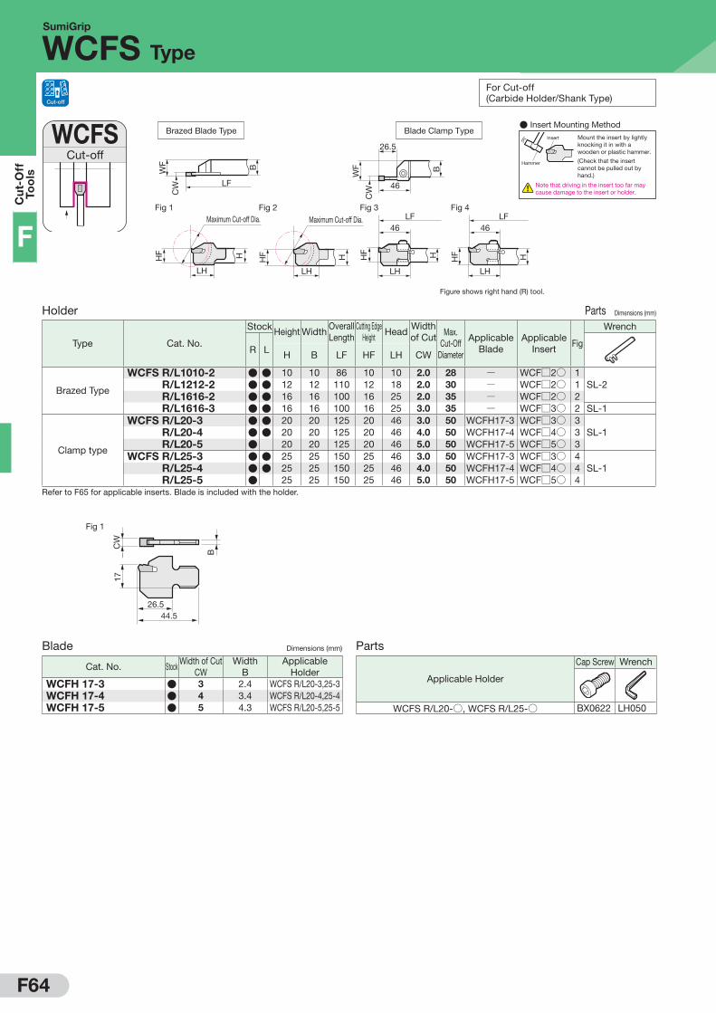
Blade Dimensions (mm)
Cat. No. StockWidth of Cut
CWWidth
BApplicable
HolderWCFH 17-3 ● 3 2.4 WCFS R/L20-3,25-3WCFH 17-4 ● 4 3.4 WCFS R/L20-4,25-4WCFH 17-5 ● 5 4.3 WCFS R/L20-5,25-5
Parts
Applicable Holder
Cap Screw Wrench
WCFS R/L20-○, WCFS R/L25-○ BX0622 LH050
SumiGrip
WCFS Type
Cut-offWCFS
Figure shows right hand (R) tool.
Blade Clamp Type
26.5
WF
CW
B
46
Fig 1 Fig 2 Fig 3 Fig 4LF
HHF
46
LH
LF
HHF
46
LH
HHF
LH
Maximum Cut-off Dia.
LH
Maximum Cut-off Dia.
HHF
Brazed Blade Type
LFC
W
BWF
Holder Parts Dimensions (mm)
Type Cat. No.
Stock Height WidthOverall Length
Cutting EdgeHeight
HeadWidth of Cut Max.
Cut-OffDiameter
Applicable Blade
ApplicableInsert
Fig
Wrench
R L H B LF HF LH CW
Brazed Type
WCFS R/L1010-2 ● ● 10 10 86 10 10 2.0 28 Q WCF□2○ 1SL-2 R/L1212-2 ● ● 12 12 110 12 18 2.0 30 Q WCF□2○ 1
R/L1616-2 ● ● 16 16 100 16 25 2.0 35 Q WCF□2○ 2 R/L1616-3 ● ● 16 16 100 16 25 3.0 35 Q WCF□3○ 2 SL-1
Clamp type
WCFS R/L20-3 ● ● 20 20 125 20 46 3.0 50 WCFH17-3 WCF□3○ 3SL-1 R/L20-4 ● ● 20 20 125 20 46 4.0 50 WCFH17-4 WCF□4○ 3
R/L20-5 ● 20 20 125 20 46 5.0 50 WCFH17-5 WCF□5○ 3WCFS R/L25-3 ● ● 25 25 150 25 46 3.0 50 WCFH17-3 WCF□3○ 4
SL-1 R/L25-4 ● ● 25 25 150 25 46 4.0 50 WCFH17-4 WCF□4○ 4 R/L25-5 ● 25 25 150 25 46 5.0 50 WCFH17-5 WCF□5○ 4
Refer to F65 for applicable inserts. Blade is included with the holder.
Cut-off For Cut-off (Carbide Holder/Shank Type)
● Insert Mounting MethodMount the insert by lightly knocking it in with a wooden or plastic hammer.
(Check that the insert cannot be pulled out by hand.)
Insert
Hammer
Note that driving in the insert too far may cause damage to the insert or holder.

F65
Cu
t-Off
Too
ls
F
Fig. 1 (Neutral (N)) Fig. 2 (Right Hand (R)) Fig. 3 (Left Hand (L))
2-RE0.2*
8°
2°2°
CW
2-RE0.2*
2°2°
CW
2-RE0.2*
8°
2°2°
CW
WCFS Insert (SumiGrip/SumiGrip Jr. Common Insert) ( Coated Carbide / Cermet / Carbide) Dimensions (mm)
Appearance Cat. No.
AC
830P
AC
225
AC
1030
UT1
500A
A30
G10
E Width of CutCW
Applicable Holder Fig
WCF N○ -GGGeneral-purpose
WCF N2-GG ● Q Q Q Q 2.0 WCFS R/L○○○○-2 1WCF N3-GG ● Q Q Q Q 3.0 WCFS R/L○○○○-3,WCFS R/L○○-3 1WCF N4-GG ● Q Q Q Q 4.0 WCFS R/L○○-4 1WCF N5-GG ● Q Q Q Q 5.0 WCFS R/L○○-5 1
WCF N○ -GFExotic Alloy Low Feed
WCF N2-GF Q ● Q Q Q 2.0 WCFS R/L○○○○-2 1WCF N3-GF Q ● Q Q Q 3.0 WCFS R/L○○○○-3,WCFS R/L○○-3 1WCF N4-GF Q ● Q Q Q 4.0 WCFS R/L○○-4 1WCF N5-GF Q ● Q Q Q 5.0 WCFS R/L○○-5 1
WCF □○ -CFExotic Alloy Low Feed (With Feed Direction)
WCF R3-CF Q ● Q Q Q 3.0 WCFS R/L○○○○-3WCFS R/L○○-3
2WCF L3-CF Q ● Q Q Q 3.0 3WCF R4-CF Q ● Q Q Q 4.0
WCFS R/L○○-42
WCF L4-CF Q ● Q Q Q 4.0 3WCF □ 2TSmall Diameter Low Resistance
WCF N2T ● Q Q Q Q Q 2.0WCFS R/L○○○○-2
1WCF R2T ● Q Q Q Q Q 2.0 2WCF L2T ● Q Q Q Q Q 2.0 3
WCF □○No Chipbreaker For General Steel
WCF N3 ● Q Q Q Q Q 3.0WCFS R/L○○○○-3WCFS R/L○○-3
1WCF R3 ● Q Q Q Q Q 3.0 2WCF L3 ● Q Q Q Q Q 3.0 3WCF N4 ● Q Q Q Q Q 4.0
WCFS R/L○○-41
WCF R4 ● Q Q Q Q Q 4.0 2WCF L4 ● Q Q Q Q Q 4.0 3WCF N5 ● Q Q Q Q Q 5.0
WCFS R/L○○-51
WCF R5 ● Q Q Q Q Q 5.0 2WCF L5 ● Q Q Q Q Q 5.0 3
WCF □○ AExotic Alloy Low Feed
WCF N2A ● Q Q 2.0 WCFS R/L○○○○-2 1WCF N3A ● Q ● ● ● 3.0
WCFS R/L○○○○-3WCFS R/L○○-3
1WCF R3A ● Q ● 3.0 2WCF L3A ● Q Q 3.0 3WCF N4A ● Q ● 4.0
WCFS R/L○○-41
WCF R4A ● Q Q 4.0 2WCF L4A ● Q Q 4.0 3WCF N5A ● Q Q 5.0
WCFS R/L○○-51
WCF R5A Q Q Q 5.0 2WCF L5A Q Q Q 5.0 3
WCF □○ BCast Iron Light Alloys
WCF N3B Q Q Q Q ● 3.0WCFS R/L○○○○-3WCFS R/L○○-3
1WCF R3B Q Q Q Q ● 3.0 2WCF L3B Q Q Q Q ● 3.0 3WCF N4B Q Q Q Q ● 4.0
WCFS R/L○○-41
WCF R4B Q Q Q Q ● 4.0 2WCF L4B Q Q Q Q 4.0 3
* Same breaker shape as the type for general steel (WCF□○), but with smaller cutting edge treatment.
WCF N5B Q Q Q Q ● 5.0WCFS R/L○○-5
1WCF R5B Q Q Q Q 5.0 2WCF L5B Q Q Q Q ● 5.0 3
SumiGrip
WCFS Type
*WCF□ 2T: 2-RE0.15
Recommended Cutting Conditions
Work MaterialCutting Speed vc (m/min)
Coated Carbide Cermet CarbideAC830P AC225 AC1030U T1500A A30 G10E
P SteelGeneral Steel 80 to200 80 to200 50 to200 80 to200 50 to120 QMild Steel 100 to230 100 to230 50 to230 100 to230 70 to150 QDie Steel 60 to150 60 to150 50 to150 60 to150 50 to120 Q
M Stainless Steel 70 to150 60 to150 50 to150 Q 70 to130 QK Cast Iron Q Q 50 to200 Q Q 50 to120N Non-ferrous Metal Q Q 200 to500 Q Q 200 to500
Chipbreaker
Feed Rate f (mm/rev)Neutral Handed Insert
GG GF No Chipbreaker T A B No Chipbreaker CF T A BGeneral-purpose Exotic Alloy /
Low Cutting Force Type General Steel Small Diameter / Low Resistance Exotic Alloy / Low Feed Cast Iron / Light Alloys General Steel Exotic Alloy /
Low Cutting Force TypeSmall Diameter / Low Resistance Exotic Alloy / Low Feed Cast Iron / Light Alloys
Width of Cut CW(mm)
2.0 0.05 to 0.20 0.03 to 0.12 Q 0.03 to 0.10 0.03 to 0.12 Q Q Q 0.03 to 0.10 Q Q3.0 0.08 to 0.25 0.04 to 0.15 0.08 to 0.25 Q 0.04 to 0.15 0.05 to 0.15 0.08 to 0.25 0.05 to 0.12 Q 0.04 to 0.15 0.05 to 0.154.0 0.10 to 0.30 0.05 to 0.18 0.10 to 0.30 Q 0.05 to 0.18 0.05 to 0.18 0.10 to 0.30 0.05 to 0.12 Q 0.05 to 0.18 0.05 to 0.185.0 0.10 to 0.35 0.05 to 0.20 0.10 to 0.30 Q 0.05 to 0.20 0.06 to 0.20 0.10 to 0.30 Q Q Q 0.06 to 0.20

F66
Cu
t-O
ff
Too
ls
F
SCTSmall Diameter Cut-off
Figure shows right hand (R) tool.
HF
1.5°
WF
LF
BH
LH
182
HF
1.5°
WF
LF
BH
LH
Fig 1 Fig 2
Holder (Right Handed) Parts Dimensions (mm)
Cat. No.
Sto
ck
Height WidthOverall Length
Cutting EdgeDistance
Cutting EdgeHeight
HeadApplicable Insert Fig
Flat Screw Wrench
H B LF WF HF LH
SCT R1010 ● 10 10 120 10 10 15CT R05○○○○(-NB)CT R12○○○○(-NB)
1BFTX0410T8L TRX08SCT R1212 ● 12 12 120 12 12 15 1
SCT R1616 ● 16 16 120 16 16 15 1SCT R1010-16 ● 10 10 120 10 10 18
CT R16○○○○(-NB)2
BFTX0410T8L TRX08SCT R1212-16 ● 12 12 120 12 12 18 1SCT R1616-16 ● 16 16 120 16 16 18 1
Holder (Left Handed) Parts Dimensions (mm)
Cat. No.
Sto
ck
Height WidthOverall Length
Cutting EdgeDistance
Cutting EdgeHeight
HeadApplicable Insert Fig
Flat Screw Wrench
H B LF WF HF LH
SCT L1010 ● 10 10 120 10 10 15CT L05○○○○(-NB)CT L12○○○○(-NB)
1BFTX0410T8R TRX08SCT L1212 ● 12 12 120 12 12 15 1
SCT L1616 ● 16 16 120 16 16 15 1SCT L1010-16 ● 10 10 120 10 10 18
CT L16○○○○(-NB)2
BFTX0410T8R TRX08SCT L1212-16 ● 12 12 120 12 12 18 1SCT L1616-16 ● 16 16 120 16 16 18 1
SEC-Small Diameter Cut-Off Tool Holders
SCT Type
Cut-off For Cut-off (Carbide Holder/Tool Block Type)
Features
Performance
Competitor's ProductSCT Type
CT Type Inserts
● Design Features
Cut
ting
Forc
e
SCT Type
(N)
0
100
Work Material: S45C (ø10mm), Width of Cut: 1.5mmvc=60m/min, f=0.06mm/rev Wet
Competitor's Product
300
200
Feed Force
Principal Force
● Cutting Force
Work Material: SUS430 (ø8mm), Width of Cut: 1.0mm (With Feed Direction)vc=45m/min, f=0.02mm/rev Wet
● Surface Finish
SCT Type Holder
Sharp cutting edge of the vertically mounted 2-corner insert with arc-shaped breaker minimises cutting force with good chip evacuation
New screw with wrench hole at both ends makes it possible to change inserts from the back
Maximum Cut-off Dia. ø5/ø12/ø16Width of Cut 0.5/1.0/1.5/2.0mmNose Radius 0.05/0mmFront Cutting Edge Angle: 0°/20°
New PVD-coated grade AC1030U/AC530U provides longer and stable tool life Insert tightening
direction indicator
Shank Size □10/12/16mm
New screw clamping system makes it possible to change comers by simply loosening the screw
Small Pip Large Pip
● Simple Indexable Inserts New clamping system makes it possible to change corners simply by loosening the screw from the back
● High quality surface finish Excellent chip removal with good surface finish even at the centre of the work material end face.
● Long, stable tool life with PVD-coated AC1030U/AC530U

F67
Cu
t-Off
Too
ls
FInserts (For Right-handed Holders) ( Coated Carbide) Dimensions (mm)
Cat. No.
AC
1030
U
AC
530U
Max.Cut-off Dia.
Width of Cut
NoseRadius
Overall Length
ThicknessChipbreaker Applicable Holder
R N L R N L CW RE L SCTR 050505 R/N/L ● ● ● ● ● ● 5 0.5 0.05
19 7 Yes
SCT R1010SCT R1212SCT R1616
CTR 050500 R/N/L ● ● ● ● 5 0.5 0CTR 121005 R/N/L ● ● ● ● ● ● 12 1.0
0.05
19 7 Yes
CTR 121505 R/N/L ● ● ● ● ● ● 12 1.5CTR 122005 R/N/L ● ● ● ● 12 2.0CTR 121000 R/N/L ● ● ● ● 12 1.0
0CTR 121500 R/N/L ● ● ● ● 12 1.5CTR 122000 R/N/L ● ● ● ● 12 2.0CTR 161005 R/N/L 16 1.0
0.05
23.1 8.3 YesSCT R1010-16SCT R1212-16SCT R1616-16
CTR 161505 R/N/L ● ● ● ● 16 1.5CTR 162005 R/N/L ● ● ● ● ● ● 16 2.0CTR 161000 R/N/L 16 1.0
0CTR 161500 R/N/L ● ● ● ● 16 1.5CTR 162000 R/N/L ● ● ● ● ● ● 16 2.0CTR 050500 R/N/L-NB 5 0.5 0 19 7 No
SCT R1010SCT R1212SCT R1616
CTR 121000 R/N/L-NB ● ● 12 1.00 19 7 NoCTR 121500 R/N/L-NB ● ● 12 1.5
CTR 122000 R/N/L-NB ● ● 12 2.0CTR 161000 R/N/L-NB 16 1.0
0 23.1 8.3 NoSCT R1010-16SCT R1212-16SCT R1616-16
CTR 161500 R/N/L-NB 16 1.5CTR 162000 R/N/L-NB ● ● 16 2.0
Inserts (For Left-handed Holders) ( Coated Carbide) Dimensions (mm)
Cat. No.
AC
1030
U
AC
530U
Max.Cut-off Dia.
Width of Cut
NoseRadius
Overall Length
ThicknessChipbreaker Applicable Holder
R N L R N L CW RE L SCTL 050505 R/N/L ● ● ● ● 5 0.5 0.05
19 7 Yes
SCT L1010SCT L1212SCT L1616
CTL 050500 R/N/L ● ● ● ● 5 0.5 0CTL 121005 R/N/L ● ● ● ● ● ● 12 1.0
0.05
19 7 Yes
CTL 121505 R/N/L ● ● ● ● ● ● 12 1.5CTL 122005 R/N/L ● ● ● ● 12 2.0CTL 121000 R/N/L ● ● ● ● 12 1.0
0CTL 121500 R/N/L ● ● ● ● 12 1.5CTL 122000 R/N/L ● ● ● ● 12 2.0CTL 161005 R/N/L 16 1.0
0.05
23.1 8.3 YesSCT L1010-16SCT L1212-16SCT L1616-16
CTL 161505 R/N/L ● ● ● ● 16 1.5CTL 162005 R/N/L ● ● ● ● ● ● 16 2.0CTL 161000 R/N/L 16 1.0
0CTL 161500 R/N/L ● ● ● ● 16 1.5CTL 162000 R/N/L ● ● ● ● 16 2.0CTL 050500 R/N/L-NB 5 0.5 0 19 7 No
SCT L1010SCT L1212SCT L1616
CTL 121000 R/N/L-NB 12 1.00 19 7 NoCTL 121500 R/N/L-NB 12 1.5
CTL 122000 R/N/L-NB 12 2.0CTL 161000 R/N/L-NB 16 1.0
0 23.1 8.3 NoSCT L1010-16SCT L1212-16SCT L1616-16
CTL 161500 R/N/L-NB 16 1.5CTL 162000 R/N/L-NB 16 2.0
SEC-Small Diameter Cut-Off Tool Holders
SCT Type
Insert Mounting Status and Dimensions (Figure shows insert with chipbreaker)
Holder Feed Direction For Right-handed Holder (SCTR) For Left-handed Holder (SCTL)Insert Cat. No. CTRSSR CTRSSN CTRSSL CTLSSR CTLSSN CTLSSL
Hol
der
M
ount
ing
Sta
tus :=20° :=20° :=20° :=20°
Inse
rt
Sha
pe
and
D
imen
sion
s
:=20°
RE
L55°
2-RE
S2.
5CW
:=20°
RE RE
:=20°
L
2.5
CW
55°
2-RE
S
RE
:=20°

F68
Cu
t-O
ff
Too
ls
F
Cut-Off (For Small Lathes)GNDM
Figure shows right hand (R) tool.
Fig 1
Maximum Cut-off Dia. LH
CW
WF2 LF
HF H
BWF
Holder Parts Dimensions (mm)
Cat. No.
Stock Height WidthOverall Length
Cutting EdgeDistance
Cutting EdgeHeight
HeadOffSet
Width of Cut Max.
Cut-off Dia.
Applicable Insert Fig
CapScrew
Wrench
R L N mH B LF WF HF LH WF2 CW
GNDM R/L1616JX-1.2508 ● ● 16 16 120 (16) 16 26 0 1.25 16 GCM N125005-GF 1
BX0515 4.0 LH040GNDM R/L1616JX-1.510 ● ● 16 16 120 (16) 16 26 0 1.50 20 GCM N150005-GF 1GNDM R/L1616JX-212 ● ● 16 16 120 (16) 16 30 0 2.00 24 GC□ □20○○-□□ 1GNDM R/L1616JX-312 ● ● 16 16 120 (16) 16 30 0 3.00 24 GC□ □30○○-□□ 1
Combine the insert with a holder such that the width of cut (CW) matches.Refer to F69 for applicable inserts.
Cut-Off (For Small Lathes)GNDL
Figure shows right hand (R) tool.
Fig 1
Maximum Cut-off Dia.
CWWF
2H
F
LH2
LH
HBH
LF
BH
WF
Fig 2
Maximum Cut-off Dia.
CW
WF2
HF
LF
BH
WF
LH
Holder Parts Dimensions (mm)
Cat. No.
Stock Height WidthOverall Length
Cutting EdgeDistance
Cutting EdgeHeight
Step Head HeadOffSet
Width of Cut Max.
Cut-off
Dia.
Applicable Insert Fig
Flat Screw/Cap Screw
Wrench
R L
BFTX0412N
BX0515
N m
LT15-10
LH040
H B LF WF HF HBH LH LH2 WF2 CW
GNDL R/L1010JX-1.2510 ● ● 10 10 120 (10) 10 2.0 18 18.3 0 1.25 20 GCM N125005-GF 1
BFTX0412N 3.0 LT15-10GNDL R/L1010JX-1.510 ● ● 10 10 120 (10) 10 2.0 18 18.3 0 1.50 20 GCM N150005-GF 1GNDL R/L1010JX-210 ● ● 10 10 120 (10) 10 2.0 22 22.3 0 2.00 20 GC□ □20○○-□□ 1GNDL R/L1010JX-310 ● ● 10 10 120 (10) 10 2.0 22 22.3 0 3.00 20 GC□ □30○○-□□ 1GNDL R/L1212JX-1.2512 ● ● 12 12 120 (12) 12 2.0 19 19.3 0 1.25 24 GCM N125005-GF 1
BFTX0412N 3.0 LT15-10GNDL R/L1212JX-1.512 ● ● 12 12 120 (12) 12 2.0 19 19.3 0 1.50 24 GCM N150005-GF 1GNDL R/L1212JX-212.5 ● ● 12 12 120 (12) 12 2.0 22 22.3 0 2.00 25 GC□ □20○○-□□ 1GNDL R/L1212JX-312.5 ● ● 12 12 120 (12) 12 2.0 22 22.3 0 3.00 25 GC□ □30○○-□□ 1GNDL R/L1616JX-1.2512.5 ● ● 16 16 120 (16) 16 Q 28 Q 0 1.25 20 GCM N125005-GF 2
BX0515 4.0 LH040GNDL R/L1616JX-1.512.5 ● ● 16 16 120 (16) 16 Q 28 Q 0 1.50 25 GCM N150005-GF 2GNDL R/L1616JX-216 ● ● 16 16 120 (16) 16 Q 32 Q 0 2.00 32 GC□ □20○○-□□ 2GNDL R/L1616JX-316 ● ● 16 16 120 (16) 16 Q 32 Q 0 3.00 32 GC□ □30○○-□□ 2
Combine the insert with a holder such that the width of cut (CW) matches.Refer to F69 for applicable inserts.
N m Recommended Tightening Torque (N·m)
SEC-Cut-Off Tool Holders (For Small Lathes)
GNDM / GNDL Type
Cut-off Zero
Offset
Cut-off Zero
Offset
F69
Cu
t-Off
Too
ls
F
Fig 1 Fig 2 Fig. 3 (Figure shows a right-handed (R) tool.)
L
4-RE
CW
S
L
S
4-RE
CW
LPSI
S
4-RE
CW
Grooving / Traverse Cutting Dimensions (mm)
Appearance Cat. No.
AC
830P
AC
425K
AC
520U
AC
530U
T250
0A Width of CutCW
NoseRadius
Overall Length
Thickness
Pcs
/Pac
k
Fig
Width of Cut Tolerance RE L S
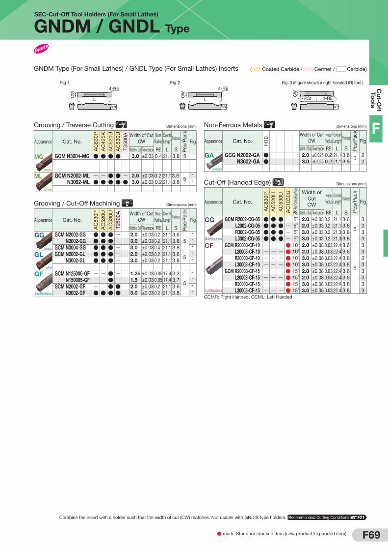
MG
General-purpose
GCM N3004-MG ● ● ● ● Q 3.0 ±0.03 0.4 21.1 3.8 5 1
GCM N2002-ML Q Q ● ● Q 2.0 ±0.03 0.2 21.1 3.65
1 N3002-ML ● ● ● ● ● 3.0 ±0.03 0.2 21.1 3.8 1
Grooving / Cut-Off Machining Dimensions (mm)
Appearance Cat. No.
AC
830P
AC
520U
AC
530U
T250
0A Width of CutCW
NoseRadius
Overall Length
Thickness
Pcs
/Pac
k
Fig
Width of Cut Tolerance RE L SGG
General-purpose
GCM N2002-GG ● ● ● Q 2.0 ±0.03 0.2 21.1 3.65
1GCM N3002-GG ● ● ● Q 3.0 ±0.03 0.2 21.1 3.8 1GCM N3004-GG ● ● ● Q 3.0 ±0.03 0.4 21.1 3.8 1
GL
Low Feed
GCM N2002-GL ● ● ● Q 2.0 ±0.03 0.2 21.1 3.65
1GCM N3002-GL ● ● ● Q 3.0 ±0.03 0.2 21.1 3.8 1
GF
Low Resistance
GCM N125005-GF Q Q ● Q 1.25 ±0.03 0.05 17.4 3.2
5
1GCM N150005-GF Q Q ● Q 1.5 ±0.03 0.05 17.4 3.7 1GCM N2002-GF Q ● ● 2.0 ±0.03 0.2 21.1 3.6 1
N3002-GF ● ● ● ● 3.0 ±0.03 0.2 21.1 3.8 1
Non-Ferrous Metals Dimensions (mm)
Appearance Cat. No.
H10
Width of CutCW
NoseRadius
Overall Length
Thickness
Pcs
/Pac
k
FigWidth of Cut Tolerance RE L S
GA
General-purpose
GCG N2002-GA ● 2.0 ±0.025 0.2 21.1 3.65
2GCG N3002-GA ● 3.0 ±0.025 0.2 21.1 3.8 2
Cut-Off (Handed Edge) Dimensions (mm)
Appearance Cat. No.
AC
830P
AC
520U
AC
530U
AC
1030
UFron
t Cutting
Edge An
gle
Width of CutCW
NoseRadius
Overall Length
Thickness
Pcs
/Pac
k
Fig
PSI Width of Cut Tolerance RE L S
CG
General-purpose
GCM R2002-CG-05 ● ● ● Q 5˚ 2.0 ±0.03 0.2 21.1 3.6
5
3GCM L2002-CG-05 ● ● ● Q 5˚ 2.0 ±0.03 0.2 21.1 3.6 3GCM R3002-CG-05 ● ● ● Q 5˚ 3.0 ±0.03 0.2 21.3 3.8 3GCM L3002-CG-05 ● ● ● Q 5˚ 3.0 ±0.03 0.2 21.3 3.8 3
CF
Low Resistance
GCM R20003-CF-10 Q Q Q ● 10˚ 2.0 ±0.08 0.03 22.4 3.6
5
3GCM L20003-CF-10 Q Q Q ● 10˚ 2.0 ±0.08 0.03 22.4 3.6 3GCM R30003-CF-10 Q Q Q ● 10˚ 3.0 ±0.08 0.03 22.4 3.8 3GCM L30003-CF-10 Q Q Q ● 10˚ 3.0 ±0.08 0.03 22.4 3.8 3GCM R20003-CF-15 Q Q Q ● 15˚ 2.0 ±0.08 0.03 22.4 3.6 3GCM L20003-CF-15 Q Q Q ● 15˚ 2.0 ±0.08 0.03 22.4 3.6 3GCM R30003-CF-15 Q Q Q ● 15˚ 3.0 ±0.08 0.03 22.4 3.8 3GCM L30003-CF-15 Q Q Q ● 15˚ 3.0 ±0.08 0.03 22.4 3.8 3
GCMR: Right Handed, GCML: Left Handed
● mark: Standard stocked item (new product/expanded item)
SEC-Cut-Off Tool Holders (For Small Lathes)
GNDM / GNDL Type
GNDM Type (For Small Lathes) / GNDL Type (For Small Lathes) Inserts ( Coated Carbide / Cermet / Carbide)
Combine the insert with a holder such that the width of cut (CW) matches. Not usable with GNDIS type holders. Recommended Cutting Conditions F21
ML
Low Feed

F70
Cu
t-O
ff
Too
ls
F
N m Recommended Tightening Torque (N·m)
SEC-Cut-off Tool Holders
GNDM Type
Cut-offGNDM Fig 1
HF
LH
LF
WF
CW
HB
Maximum Cut-off Dia.
Figure shows right hand (R) tool.
Holder Parts Dimensions (mm)
Cat. No.
Stock Height WidthOverall Length
Cutting EdgeDistance
Cutting EdgeHeight
HeadWidth of Cut Max.
Cut-off Dia.
Applicable Insert Fig
Cap Screw Wrench
R L
BX0520
BX0620
N mH B LF WF HF LH CW
GNDM R/L2020K-1.2510 ● ● 20 20 125 20 20 34.0 1.25 20 GCM N125005-GF 1
BX0520 5.0 LH040
GNDM R/L2020K-1.510 ● ● 20 20 125 20 20 34.0 1.50 20 GCM N150005-GF 1GNDM R/L2020K-210 ● ● 20 20 125 20 20 33.6 2.00 20 GC□ □20○○-□□ 1GNDM R/L2020K-312 ● ● 20 20 125 20 20 36.6 3.00 24 GC□ □30○○-□□ 1GNDM R/L2020K-418 ● ● 20 20 125 20 20 45.0 4.00 36 GC□ □40○○-□□ 1GNDM R/L2020K-518 ● ● 20 20 125 20 20 45.0 5.00 36 GC□ N50○○-□□ 1GNDM R/L2020K-618 ● ● 20 20 125 20 20 45.0 6.00 36 GC□ N60○○-□□ 1GNDM R/L2525M-1.2510 ● ● 25 25 150 25 25 36.0 1.25 20 GCM N125005-GF 1
BX0520 5.0 LH040
GNDM R/L2525M-1.510 ● ● 25 25 150 25 25 36.0 1.50 20 GCM N150005-GF 1GNDM R/L2525M-210 ● ● 25 25 150 25 25 33.6 2.00 20 GC□ □20○○-□□ 1GNDM R/L2525M-312 ● ● 25 25 150 25 25 36.6 3.00 24 GC□ □30○○-□□ 1GNDM R/L2525M-418 ● ● 25 25 150 25 25 45.0 4.00 36 GC□ □40○○-□□ 1GNDM R/L2525M-518 ● ● 25 25 150 25 25 45.0 5.00 36 GC□ N50○○-□□ 1GNDM R/L2525M-618 ● ● 25 25 150 25 25 45.0 6.00 36 GC□ N60○○-□□ 1GNDM R/L3225P-312 32 25 170 25 32 36.6 3.00 24 GC□ □30○○-□□ 1
BX0520 5.0 LH040GNDM R/L3225P-418 32 25 170 25 32 45.0 4.00 36 GC□ □40○○-□□ 1GNDM R/L3225P-518 32 25 170 25 32 45.0 5.00 36 GC□ N50○○-□□ 1GNDM R/L3225P-618 32 25 170 25 32 45.0 6.00 36 GC□ N60○○-□□ 1GNDM R/L3225P-718 32 25 170 25 32 50.0 7.00 36 GCM N70○○-□□ 1
BX0620 6.0 LH050GNDM R/L3225P-818 32 25 170 25 32 50.0 8.00 36 GCM N80○○-□□ 1GNDM R/L3232P-312 ● ● 32 32 170 32 32 36.6 3.00 24 GC□ □30○○-□□ 1
BX0620 6.0 LH050
GNDM R/L3232P-418 ● ● 32 32 170 32 32 45.0 4.00 36 GC□ □40○○-□□ 1GNDM R/L3232P-518 ● ● 32 32 170 32 32 45.0 5.00 36 GC□ N50○○-□□ 1GNDM R/L3232P-618 ● ● 32 32 170 32 32 45.0 6.00 36 GC□ N60○○-□□ 1GNDM R/L3232P-718 ● ● 32 32 170 32 32 50.0 7.00 36 GCM N70○○-□□ 1GNDM R/L3232P-818 ● ● 32 32 170 32 32 50.0 8.00 36 GCM N80○○-□□ 1
Combine the insert with a holder such that the width of cut (CW) matches. The maximum cut-off diameter indicated above is for inserts with RE=0.2 mm.Refer to F71 for applicable inserts.
Cut-off

F71
Cu
t-Off
Too
ls
F
Fig 1 Fig 2 Fig. 3 (Figure shows a right-handed (R) tool.)
L
4-RE
CW
S
L
S
4-RE
CW
LPSI
S
4-RE
CW
Grooving / Traverse Cutting Dimensions (mm)
Appearance Cat. No.
AC
830P
AC
425K
AC
520U
AC
530U
T250
0A Width of CutCW
NoseRadius
Overall Length
Thickness
Pcs/
Pack
Fig
Width of Cut Tolerance RE L SMG
General-purpose
GCM N3004-MG ● ● ● ● Q 3.0 ±0.03 0.4 21.1 3.8
5
1GCM N4008-MG ● ● ● ● Q 4.0 ±0.03 0.8 26.4 4.0 1
N5008-MG ● ● ● ● Q 5.0 ±0.03 0.8 26.4 4.1 1 N6008-MG ● ● ● ● Q 6.0 ±0.03 0.8 26.4 4.5 1
GCM N7008-MG ● ● ● ● Q 7.0 ±0.04 0.8 28.75 5.5 1GCM N8008-MG ● ● ● ● Q 8.0 ±0.04 0.8 28.75 6.0 1
ML
Low Feed
GCM N2002-ML Q Q ● ● Q 2.0 ±0.03 0.2 21.1 3.6
5
1 N3002-ML ● ● ● ● ● 3.0 ±0.03 0.2 21.1 3.8 1
GCM N4004-ML ● ● ● ● ● 4.0 ±0.03 0.4 26.4 4.0 1GCM N5004-ML ● ● ● ● Q 5.0 ±0.03 0.4 26.4 4.1 1
N6004-ML ● ● ● ● Q 6.0 ±0.03 0.4 26.4 4.5 1GCM N7004-ML ● ● ● ● Q 7.0 ±0.04 0.4 28.75 5.5 1GCM N8004-ML ● ● ● ● Q 8.0 ±0.04 0.4 28.75 6.0 1
Grooving / Cut-Off Machining Dimensions (mm)
Appearance Cat. No.
AC
830P
AC
520U
AC
530U
T250
0A Width of CutCW
NoseRadius
Overall Length
Thickness
Pcs/
Pack
Fig
Width of Cut Tolerance RE L S
GG
General-purpose
GCM N2002-GG ● ● ● Q 2.0 ±0.03 0.2 21.1 3.6
5
1GCM N3002-GG ● ● ● Q 3.0 ±0.03 0.2 21.1 3.8 1
N4002-GG ● ● ● Q 4.0 ±0.03 0.2 26.4 4.0 1GCM N5002-GG ● ● ● Q 5.0 ±0.03 0.2 26.4 4.1 1GCM N6002-GG ● ● ● Q 6.0 ±0.03 0.2 26.4 4.5 1GCM N3004-GG ● ● ● Q 3.0 ±0.03 0.4 21.1 3.8 1GCM N4004-GG ● ● ● Q 4.0 ±0.03 0.4 26.4 4.0 1GCM N5004-GG ● ● ● Q 5.0 ±0.03 0.4 26.4 4.1 1GCM N6004-GG ● ● ● Q 6.0 ±0.03 0.4 26.4 4.5 1GCM N7004-GG ● ● ● Q 7.0 ±0.04 0.4 28.75 5.5 1GCM N8004-GG ● ● ● Q 8.0 ±0.04 0.4 28.75 6.0 1
GL
Low Feed
GCM N2002-GL ● ● ● Q 2.0 ±0.03 0.2 21.1 3.6
5
1 N3002-GL ● ● ● Q 3.0 ±0.03 0.2 21.1 3.8 1
GCM N4002-GL ● ● ● Q 4.0 ±0.03 0.2 26.4 4.0 1GCM N5002-GL ● ● ● Q 5.0 ±0.03 0.2 26.4 4.1 1GCM N6002-GL ● ● ● Q 6.0 ±0.03 0.2 26.4 4.5 1GCM N7004-GL ● ● ● Q 7.0 ±0.04 0.4 28.75 5.5 1GCM N8004-GL ● ● ● Q 8.0 ±0.04 0.4 28.75 6.0 1
GF
Low Resistance
GCM N125005-GF Q Q ● Q 1.25 ±0.03 0.05 17.4 3.2
5
1GCM N150005-GF Q Q ● Q 1.5 ±0.03 0.05 17.4 3.7 1GCM N2002-GF Q ● ● 2.0 ±0.03 0.2 21.1 3.6 1
N3002-GF ● ● ● ● 3.0 ±0.03 0.2 21.1 3.8 1 N4002-GF ● ● ● ● 4.0 ±0.03 0.2 26.4 4.0 1
GCM N5002-GF ● ● ● Q 5.0 ±0.03 0.2 26.4 4.1 1 N6002-GF ● ● ● Q 6.0 ±0.03 0.2 26.4 4.5 1
GCM N7002-GF ● ● ● Q 7.0 ±0.04 0.2 28.75 5.5 1GCM N8002-GF ● ● ● Q 8.0 ±0.04 0.2 28.75 6.0 1GCM N7004-GF ● ● ● Q 7.0 ±0.04 0.4 28.75 5.5
51
GCM N8004-GF ● ● ● Q 8.0 ±0.04 0.4 28.75 6.0 1
Non-Ferrous Metals Dimensions (mm)
Appearance Cat. No.
H10
Width of CutCW
NoseRadius
Overall Length
Thickness
Pcs/
Pack
FigWidth of Cut Tolerance RE L S
GA
General-purpose
GCG N2002-GA ● 2.0 ±0.025 0.2 21.1 3.6
5
2GCG N3002-GA ● 3.0 ±0.025 0.2 21.1 3.8 2GCG N4004-GA ● 4.0 ±0.025 0.4 26.4 4.0 2GCG N5004-GA ● 5.0 ±0.025 0.4 26.4 4.1 2GCG N6004-GA ● 6.0 ±0.025 0.4 26.4 4.5 2
Cut-Off (Handed Edge) Dimensions (mm)
Appearance Cat. No.
AC
830P
AC
520U
AC
530U
AC
1030
UFron
t Cutting
Edge An
gle Width of CutCW
NoseRadius
Overall Length
Thickness
Pcs
/Pac
k
Fig
PSI Width of Cut Tolerance RE L SCG
General-purpose
GCM R2002-CG-05 ● ● ● Q 5˚ 2.0 ±0.03 0.2 21.1 3.6
5
3GCM L2002-CG-05 ● ● ● Q 5˚ 2.0 ±0.03 0.2 21.1 3.6 3GCM R3002-CG-05 ● ● ● Q 5˚ 3.0 ±0.03 0.2 21.3 3.8 3GCM L3002-CG-05 ● ● ● Q 5˚ 3.0 ±0.03 0.2 21.3 3.8 3GCM R4002-CG-05 ● ● ● Q 5˚ 4.0 ±0.04 0.2 26.7 4.0 3GCM L4002-CG-05 ● ● ● Q 5˚ 4.0 ±0.04 0.2 26.7 4.0 3
CF
Low Resistance
GCM R20003-CF-10 Q Q Q ● 10˚ 2.0 ±0.08 0.03 22.4 3.6
5
3GCM L20003-CF-10 Q Q Q ● 10˚ 2.0 ±0.08 0.03 22.4 3.6 3GCM R30003-CF-10 Q Q Q ● 10˚ 3.0 ±0.08 0.03 22.4 3.8 3GCM L30003-CF-10 Q Q Q ● 10˚ 3.0 ±0.08 0.03 22.4 3.8 3GCM R20003-CF-15 Q Q Q ● 15˚ 2.0 ±0.08 0.03 22.4 3.6 3GCM L20003-CF-15 Q Q Q ● 15˚ 2.0 ±0.08 0.03 22.4 3.6 3GCM R30003-CF-15 Q Q Q ● 15˚ 3.0 ±0.08 0.03 22.4 3.8 3GCM L30003-CF-15 Q Q Q ● 15˚ 3.0 ±0.08 0.03 22.4 3.8 3
GCMR: Right Handed, GCML: Left Handed
● mark: Standard stocked item (new product/expanded item)
SEC-Cut-off Tool Holders
GNDM Type
GNDM Type Inserts ( Coated Carbide / Cermet / Carbide)
Combine the insert with a holder such that the width of cut (CW) matches. Not usable with GNDIS type holders. Recommended Cutting Conditions F21

F72
Cu
t-O
ff
Too
ls
F
Fig 1
L
Width across Flats: 14 Width across Flats: 12
Parts (Hose) Dimensions (mm)
Cat. No. Stock L Screw Standard Screw Standard FigJ-HOSE-G1/8-G1/8-200 ● 200 G1/8 G1/8 1J-HOSE-G1/8-G1/8-300 ● 300 G1/8 G1/8 1
Hoses are sold separately.
Fig 1 Fig 2
29
14 R1/8 G1/814 20
21
R1/8
G1/8
Parts (Connector) Dimensions (mm)
Cat. No. Stock Screw Standard Screw Standard FigJ-G1/8-R1/8-00 ● G1/8 R1/8 1J-G1/8-R1/8-90 ● G1/8 R1/8 2
Connectors are sold separately.
N m Recommended Tightening Torque (N·m) ● mark: Standard stocked item (new product/expanded item)
SEC-Cut-off Tool Holders
GNDM-J Type
GNDM-J
*
Cut-off
Fig 1
Figure shows right hand (R) tool.
LF
LH
CW
BHHF
WF
Rc1/8
Rc1/8
Maximum Cut-off Dia.
Holder Parts Dimensions (mm)
Cat. No.
Stock Height WidthOverall Length
Cutting EdgeDistance
Cutting EdgeHeight
HeadWidth of Cut Max.
Cut-OffDiameter
Applicable Insert Fig
Cap Screw
Plug Wrench
R L N mH B LF WF HF LH CW
GNDM R/L2020K-210J ● ● 20 20 125 20 20 33.6 2.00 20 GC□ □20○○-□□ 1
BX0520 6.0 XP02 LH040GNDM R/L2020K-312J ● ● 20 20 125 20 20 36.6 3.00 24 GC□ □30○○-□□ 1GNDM R/L2020K-418J ● ● 20 20 125 20 20 45 4.00 36 GC□ □40○○-□□ 1GNDM R/L2020K-518J ● ● 20 20 125 20 20 45 5.00 36 GC□ N50○○-□□ 1GNDM R/L2020K-618J ● ● 20 20 125 20 20 45 6.00 36 GC□ N60○○-□□ 1GNDM R/L2525K-210J ● ● 25 25 125 25 25 33.6 2.00 20 GC□ □20○○-□□ 1
BX0520 6.0 XP02 LH040GNDM R/L2525K-312J ● ● 25 25 125 25 25 36.6 3.00 24 GC□ □30○○-□□ 1GNDM R/L2525K-418J ● ● 25 25 125 25 25 45 4.00 36 GC□ □40○○-□□ 1GNDM R/L2525K-518J ● ● 25 25 125 25 25 45 5.00 36 GC□ N50○○-□□ 1GNDM R/L2525K-618J ● ● 25 25 125 25 25 45 6.00 36 GC□ N60○○-□□ 1
Combine the insert with a holder such that the width of cut (CW) matches. The maximum cut-off diameter indicated above is for inserts with RE = 0.2 mm.Refer to F73 for applicable inserts.
Cut-off InternalCoolant
· GNDM-J/GNDL-J Type holders have a plug (XP02) mounted on the holder back end at shipping. (See Fig. 1) When piping from the holder back end, mount a plug (XP02) on the bottom of the holder for use. (See Fig. 2)
· Apply sealant such as commercial sealing tape to the piping connection parts.
HoseJ-HOSE-G1/8-G1/8-200 (Overall length 200mm)
J-HOSE-G1/8-G1/8-300 (Overall length 300mm)
200300
Connector (Straight)
J-G1/8-R1/8-0000
Piping Method for Hoses and Connectors
Connector (L-Shaped)J-G1/8-R1/8-9090
Connector (Straight)
J-G1/8-R1/8-0000Machine
Connector (L-Shaped)
J-G1/8-R1/8-9090
Internal Coolant HolderGNDM-J Type/GNDL-J TypeJ J R1/8
Rc1/8
G1/8 G1/8Rc1/8
G1/8
G1/8R1/8
R1/8G1/8
G1/8R1/8
Fig. 1 Piping from bottom (at shipping)
Piping from bottom
Plug XP02
Fig. 2 Piping from back end
Piping from back end
Plug XP02

F73
Cu
t-Off
Too
ls
F
Fig 1 Fig. 3 (Figure shows a right-handed (R) tool.)
L
4-RE
CW
S
Fig 2
L
S
4-RE
CW
LPSI
S
4-RE
CW
Grooving / Traverse Cutting Dimensions (mm)
Appearance Cat. No.
AC
830P
AC
425K
AC
520U
AC
530U
T250
0A Width of CutCW
NoseRadius
Overall Length
Thickness
Pcs
/Pac
k
Fig
Width of Cut Tolerance RE L SMG
General-purpose
GCM N3004-MG ● ● ● ● Q 3.0 ±0.03 0.4 21.1 3.8
5
1GCM N4008-MG ● ● ● ● Q 4.0 ±0.03 0.8 26.4 4.0 1
N5008-MG ● ● ● ● Q 5.0 ±0.03 0.8 26.4 4.1 1GCM N6008-MG ● ● ● ● Q 6.0 ±0.03 0.8 26.4 4.5 1
CW =up to 4.0mm
CW =5.0mm up
ML
Low Feed
GCM N2002-ML Q Q ● ● Q 2.0 ±0.03 0.2 21.1 3.6
5
1 N3002-ML ● ● ● ● ● 3.0 ±0.03 0.2 21.1 3.8 1
GCM N4004-ML ● ● ● ● ● 4.0 ±0.03 0.4 26.4 4.0 1GCM N5004-ML ● ● ● ● Q 5.0 ±0.03 0.4 26.4 4.1 1
N6004-ML ● ● ● ● Q 6.0 ±0.03 0.4 26.4 4.5 1
Grooving / Cut-Off Machining Dimensions (mm)
Appearance Cat. No.
AC
830P
AC
520U
AC
530U
T250
0A Width of CutCW
NoseRadius
Overall Length
Thickness
Pcs
/Pac
k
Fig
Width of Cut Tolerance RE L SGG
General-purpose
GCM N2002-GG ● ● ● Q 2.0 ±0.03 0.2 21.1 3.6
5
1GCM N3002-GG ● ● ● Q 3.0 ±0.03 0.2 21.1 3.8 1
N4002-GG ● ● ● Q 4.0 ±0.03 0.2 26.4 4.0 1GCM N5002-GG ● ● ● Q 5.0 ±0.03 0.2 26.4 4.1 1GCM N6002-GG ● ● ● Q 6.0 ±0.03 0.2 26.4 4.5 1GCM N3004-GG ● ● ● Q 3.0 ±0.03 0.4 21.1 3.8
5
1GCM N4004-GG ● ● ● Q 4.0 ±0.03 0.4 26.4 4.0 1GCM N5004-GG ● ● ● Q 5.0 ±0.03 0.4 26.4 4.1 1GCM N6004-GG ● ● ● Q 6.0 ±0.03 0.4 26.4 4.5 1
GL
Low Feed
GCM N2002-GL ● ● ● Q 2.0 ±0.03 0.2 21.1 3.6
5
1 N3002-GL ● ● ● Q 3.0 ±0.03 0.2 21.1 3.8 1
GCM N4002-GL ● ● ● Q 4.0 ±0.03 0.2 26.4 4.0 1GCM N5002-GL ● ● ● Q 5.0 ±0.03 0.2 26.4 4.1 1GCM N6002-GL ● ● ● Q 6.0 ±0.03 0.2 26.4 4.5 1
GF
Low Resistance
GCM N2002-GF Q ● ● 2.0 ±0.03 0.2 21.1 3.6
5
1 N3002-GF ● ● ● ● 3.0 ±0.03 0.2 21.1 3.8 1 N4002-GF ● ● ● ● 4.0 ±0.03 0.2 26.4 4.0 1
GCM N5002-GF ● ● ● Q 5.0 ±0.03 0.2 26.4 4.1 1 N6002-GF ● ● ● Q 6.0 ±0.03 0.2 26.4 4.5 1
Non-Ferrous Metals Dimensions (mm)
Appearance Cat. No.
H10
Width of CutCW
NoseRadius
Overall Length
Thickness
Pcs
/Pac
k
FigWidth of Cut Tolerance RE L S
GA
General-purpose
GCG N2002-GA ● 2.0 ±0.025 0.2 21.1 3.6
5
2GCG N3002-GA ● 3.0 ±0.025 0.2 21.1 3.8 2GCG N4004-GA ● 4.0 ±0.025 0.4 26.4 4.0 2GCG N5004-GA ● 5.0 ±0.025 0.4 26.4 4.1 2GCG N6004-GA ● 6.0 ±0.025 0.4 26.4 4.5 2
Cut-Off (Handed Edge) Dimensions (mm)
Appearance Cat. No.
AC
830P
AC
520U
AC
530U
AC
1030
UFron
t Cutting
Edge An
gle
Width of CutCW
NoseRadius
Overall Length
Thickness
Pcs
/Pac
k
Fig
PSI Width of Cut Tolerance RE L S
CG
General-purpose
GCM R2002-CG-05 ● ● ● Q 5˚ 2.0 ±0.03 0.2 21.1 3.6
5
3GCM L2002-CG-05 ● ● ● Q 5˚ 2.0 ±0.03 0.2 21.1 3.6 3GCM R3002-CG-05 ● ● ● Q 5˚ 3.0 ±0.03 0.2 21.3 3.8 3GCM L3002-CG-05 ● ● ● Q 5˚ 3.0 ±0.03 0.2 21.3 3.8 3GCM R4002-CG-05 ● ● ● Q 5˚ 4.0 ±0.04 0.2 26.7 4.0 3GCM L4002-CG-05 ● ● ● Q 5˚ 4.0 ±0.04 0.2 26.7 4.0 3
CF
Low Resistance
GCM R20003-CF-10 Q Q Q ● 10˚ 2.0 ±0.08 0.03 22.4 3.6
5
3GCM L20003-CF-10 Q Q Q ● 10˚ 2.0 ±0.08 0.03 22.4 3.6 3GCM R30003-CF-10 Q Q Q ● 10˚ 3.0 ±0.08 0.03 22.4 3.8 3GCM L30003-CF-10 Q Q Q ● 10˚ 3.0 ±0.08 0.03 22.4 3.8 3GCM R20003-CF-15 Q Q Q ● 15˚ 2.0 ±0.08 0.03 22.4 3.6 3GCM L20003-CF-15 Q Q Q ● 15˚ 2.0 ±0.08 0.03 22.4 3.6 3GCM R30003-CF-15 Q Q Q ● 15˚ 3.0 ±0.08 0.03 22.4 3.8 3GCM L30003-CF-15 Q Q Q ● 15˚ 3.0 ±0.08 0.03 22.4 3.8 3
GCMR: Right Handed, GCML: Left Handed
● mark: Standard stocked item (expanded item)
SEC-Cut-off Tool Holders
GNDM-J Type
GNDM-J Type Inserts ( Carbide Carbide / Cermet / Carbide)
Combine the insert with a holder such that the width of cut (CW) matches. Not usable with GNDIS type holders. Recommended Cutting Conditions F21

F74
Cu
t-O
ff
Too
ls
F
N m Recommended Tightening Torque (N·m)
SEC-Cut-off Tool Holders
GNDL Type
Cut-offGNDL Fig 1
Figure shows right hand (R) tool.
LH
LF
HB
CW
WF
Maximum Cut-off Dia.
HF
Holder Parts Dimensions (mm)
Cat. No.
Stock
Height WidthOverall Length
Cutting Edge
Distance
Cutting Edge
HeightHead
Width of Cut Max.
Cut-off Dia.
Applicable Insert Fig
CapScrew
Wrench
R L
BX0520
BX0620
N m
H B LF WF HF LH CW
GNDL R/L2020K-1.2516 ● ● 20 20 125 20 20 38.0 1.25 32 GCM N125005-GF 1
BX0520 5.0 LH040
GNDL R/L2020K-1.516 ● ● 20 20 125 20 20 38.0 1.50 32 GCM N150005-GF 1GNDL R/L2020K-220 ● ● 20 20 125 20 20 44.5 2.00 40 GC□ □20○○-□□ 1GNDL R/L2020K-320 ● ● 20 20 125 20 20 44.5 3.00 40 GC□ □30○○-□□ 1GNDL R/L2020K-425 ● ● 20 20 125 20 20 50.0 4.00 50 GC□ □40○○-□□ 1GNDL R/L2020K-525 ● ● 20 20 125 20 20 50.0 5.00 50 GC□ N50○○-□□ 1GNDL R/L2020K-625 ● ● 20 20 125 20 20 50.0 6.00 50 GC□ N60○○-□□ 1GNDL R/L2525M-1.2516 ● ● 25 25 150 25 25 40.0 1.25 32 GCM N125005-GF 1
BX0520 5.0 LH040
GNDL R/L2525M-1.516 ● ● 25 25 150 25 25 40.0 1.50 32 GCM N150005-GF 1GNDL R/L2525M-220 ● ● 25 25 150 25 25 44.5 2.00 40 GC□ □20○○-□□ 1GNDL R/L2525M-320 ● ● 25 25 150 25 25 44.5 3.00 40 GC□ □30○○-□□ 1GNDL R/L2525M-425 ● ● 25 25 150 25 25 50.0 4.00 50 GC□ □40○○-□□ 1GNDL R/L2525M-525 ● ● 25 25 150 25 25 50.0 5.00 50 GC□ N50○○-□□ 1GNDL R/L2525M-625 ● ● 25 25 150 25 25 50.0 6.00 50 GC□ N60○○-□□ 1GNDL R/L3225P-320 32 25 170 25 32 44.5 3.00 40 GC□ □30○○-□□ 1
BX0520 5.0 LH040GNDL R/L3225P-425 32 25 170 25 32 50.0 4.00 50 GC□ □40○○-□□ 1GNDL R/L3225P-525 32 25 170 25 32 50.0 5.00 50 GC□ N50○○-□□ 1GNDL R/L3225P-625 32 25 170 25 32 50.0 6.00 50 GC□ N60○○-□□ 1GNDL R/L3225P-725 32 25 170 25 32 50.0 7.00 50 GCM N70○○-□□ 1
BX0620 6.0 LH050GNDL R/L3225P-825 32 25 170 25 32 50.0 8.00 50 GCM N80○○-□□ 1GNDL R/L3232P-320 ● ● 32 32 170 32 32 44.5 3.00 40 GC□ □30○○-□□ 1
BX0620 6.0 LH050
GNDL R/L3232P-425 ● ● 32 32 170 32 32 50.0 4.00 50 GC□ □40○○-□□ 1GNDL R/L3232P-525 ● ● 32 32 170 32 32 50.0 5.00 50 GC□ N50○○-□□ 1GNDL R/L3232P-625 ● ● 32 32 170 32 32 50.0 6.00 50 GC□ N60○○-□□ 1GNDL R/L3232P-725 ● ● 32 32 170 32 32 50.0 7.00 50 GCM N70○○-□□ 1GNDL R/L3232P-825 ● ● 32 32 170 32 32 50.0 8.00 50 GCM N80○○-□□ 1
Combine the insert with a holder such that the width of cut (CW) matches. The maximum cut-off diameter indicated above is for inserts with RE = 0.2 mm.Refer to F75 for applicable inserts.
Cut-off

F75
Cu
t-Off
Too
ls
F
Fig 1 Fig 2 Fig. 3 (This figure shows a right-handed (R) tool.)
L
4-RE
CW
S
L
S
4-RE
CW
LPSI
S
4-RE
CW
Grooving / Traverse Cutting Dimensions (mm)
Appearance Cat. No.
AC
830P
AC
425K
AC
520U
AC
530U
T250
0A Width of CutCW
NoseRadius
Overall Length
Thickness
Pcs
/Pac
k
Fig
Width of Cut Tolerance RE L S
MG
General-purpose
GCM N3004-MG ● ● ● ● Q 3.0 ±0.03 0.4 21.1 3.8
5
1GCM N4008-MG ● ● ● ● Q 4.0 ±0.03 0.8 26.4 4.0 1
N5008-MG ● ● ● ● Q 5.0 ±0.03 0.8 26.4 4.1 1 N6008-MG ● ● ● ● Q 6.0 ±0.03 0.8 26.4 4.5 1
GCM N7008-MG ● ● ● ● Q 7.0 ±0.04 0.8 28.75 5.5 1GCM N8008-MG ● ● ● ● Q 8.0 ±0.04 0.8 28.75 6.0 1
CW =up to 4.0mm
CW =5.0mm up
ML
Low Feed
GCM N2002-ML Q Q ● ● Q 2.0 ±0.03 0.2 21.1 3.6
5
1 N3002-ML ● ● ● ● ● 3.0 ±0.03 0.2 21.1 3.8 1
GCM N4004-ML ● ● ● ● ● 4.0 ±0.03 0.4 26.4 4.0 1 N5004-ML ● ● ● ● Q 5.0 ±0.03 0.4 26.4 4.1 1 N6004-ML ● ● ● ● Q 6.0 ±0.03 0.4 26.4 4.5 1
GCM N7004-ML ● ● ● ● Q 7.0 ±0.04 0.4 28.75 5.5 1GCM N8004-ML ● ● ● ● Q 8.0 ±0.04 0.4 28.75 6.0 1
Grooving / Cut-Off Machining Dimensions (mm)
Appearance Cat. No.
AC
830P
AC
520U
AC
530U
T250
0A Width of CutCW
NoseRadius
Overall Length
Thickness
Pcs
/Pac
k
Fig
Width of Cut Tolerance RE L S
GG
General-purpose
GCM N2002-GG ● ● ● Q 2.0 ±0.03 0.2 21.1 3.6
5
1GCM N3002-GG ● ● ● Q 3.0 ±0.03 0.2 21.1 3.8 1GCM N4002-GG ● ● ● Q 4.0 ±0.03 0.2 26.4 4.0 1GCM N5002-GG ● ● ● Q 5.0 ±0.03 0.2 26.4 4.1 1GCM N6002-GG ● ● ● Q 6.0 ±0.03 0.2 26.4 4.5 1GCM N3004-GG ● ● ● Q 3.0 ±0.03 0.4 21.1 3.8
5
1GCM N4004-GG ● ● ● Q 4.0 ±0.03 0.4 26.4 4.0 1GCM N5004-GG ● ● ● Q 5.0 ±0.03 0.4 26.4 4.1 1GCM N6004-GG ● ● ● Q 6.0 ±0.03 0.4 26.4 4.5 1GCM N7004-GG ● ● ● Q 7.0 ±0.04 0.4 28.75 5.5 1GCM N8004-GG ● ● ● Q 8.0 ±0.04 0.4 28.75 6.0 1
GL
Low Feed
GCM N2002-GL ● ● ● Q 2.0 ±0.03 0.2 21.1 3.6
5
1GCM N3002-GL ● ● ● Q 3.0 ±0.03 0.2 21.1 3.8 1GCM N4002-GL ● ● ● Q 4.0 ±0.03 0.2 26.4 4.0 1GCM N5002-GL ● ● ● Q 5.0 ±0.03 0.2 26.4 4.1 1GCM N6002-GL ● ● ● Q 6.0 ±0.03 0.2 26.4 4.5 1GCM N7004-GL ● ● ● Q 7.0 ±0.04 0.4 28.75 5.5 1GCM N8004-GL ● ● ● Q 8.0 ±0.04 0.4 28.75 6.0 1
GF
Low Resistance
GCM N125005-GF Q Q ● Q 1.25 ±0.03 0.05 17.4 3.2
5
1GCM N150005-GF Q Q ● Q 1.5 ±0.03 0.05 21.1 3.7 1GCM N2002-GF Q ● ● 2.0 ±0.03 0.2 21.1 3.6 1GCM N3002-GF ● ● ● ● 3.0 ±0.03 0.2 21.1 3.8 1GCM N4002-GF ● ● ● ● 4.0 ±0.03 0.2 26.4 4.0 1GCM N5002-GF ● ● ● Q 5.0 ±0.03 0.2 26.4 4.1 1GCM N6002-GF ● ● ● Q 6.0 ±0.03 0.2 26.4 4.5 1GCM N7002-GF ● ● ● Q 7.0 ±0.04 0.2 28.75 5.5 1GCM N8002-GF ● ● ● Q 8.0 ±0.04 0.2 28.75 6.0 1GCM N7004-GF ● ● ● Q 7.0 ±0.04 0.4 28.75 5.5
51
GCM N8004-GF ● ● ● Q 8.0 ±0.04 0.4 28.75 6.0 1
SEC-Cut-off Tool Holders
GNDL Type
GNDL Type Inserts ( Coating Carbide / Cermet / Carbide)
Non-Ferrous Metals Dimensions (mm)
Appearance Cat. No.
H10
Width of CutCW
NoseRadius
Overall Length
Thickness
Pcs
/Pac
k
FigWidth of Cut Tolerance RE L S
GA
General-purpose
GCG N2002-GA ● 2.0 ±0.025 0.2 21.1 3.6
5
2GCG N3002-GA ● 3.0 ±0.025 0.2 21.1 3.8 2GCG N4004-GA ● 4.0 ±0.025 0.4 26.4 4.0 2GCG N5004-GA ● 5.0 ±0.025 0.4 26.4 4.1 2GCG N6004-GA ● 6.0 ±0.025 0.4 26.4 4.5 2
Cut-Off (Handed Edge) Dimensions (mm)
Appearance Cat. No.
AC
830P
AC
520U
AC
530U
AC
1030
UFron
t Cutting
Edge An
gle
Width of CutCW
NoseRadius
Overall Length
Thickness
Pcs
/Pac
k
Fig
PSI Width of Cut Tolerance RE L S
CG
General-purpose
GCM R2002-CG-05 ● ● ● Q 5˚ 2.0 ±0.03 0.2 21.1 3.6
5
3GCM L2002-CG-05 ● ● ● Q 5˚ 2.0 ±0.03 0.2 21.1 3.6 3GCM R3002-CG-05 ● ● ● Q 5˚ 3.0 ±0.03 0.2 21.3 3.8 3GCM L3002-CG-05 ● ● ● Q 5˚ 3.0 ±0.03 0.2 21.3 3.8 3GCM R4002-CG-05 ● ● ● Q 5˚ 4.0 ±0.04 0.2 26.7 4.0 3GCM L4002-CG-05 ● ● ● Q 5˚ 4.0 ±0.04 0.2 26.7 4.0 3
CF
Low Resistance
GCM R20003-CF-10 Q Q Q ● 10˚ 2.0 ±0.08 0.03 22.4 3.6
5
3GCM L20003-CF-10 Q Q Q ● 10˚ 2.0 ±0.08 0.03 22.4 3.6 3GCM R30003-CF-10 Q Q Q ● 10˚ 3.0 ±0.08 0.03 22.4 3.8 3GCM L30003-CF-10 Q Q Q ● 10˚ 3.0 ±0.08 0.03 22.4 3.8 3GCM R20003-CF-15 Q Q Q ● 15˚ 2.0 ±0.08 0.03 22.4 3.6 3GCM L20003-CF-15 Q Q Q ● 15˚ 2.0 ±0.08 0.03 22.4 3.6 3GCM R30003-CF-15 Q Q Q ● 15˚ 3.0 ±0.08 0.03 22.4 3.8 3GCM L30003-CF-15 Q Q Q ● 15˚ 3.0 ±0.08 0.03 22.4 3.8 3
GCMR: Right Handed, GCML: Left Handed
Combine the insert with a holder such that the width of cut (CW) matches. Not usable with GNDIS type holders. Recommended Cutting Conditions F21

F76
Cu
t-O
ff
Too
ls
F
Fig 1
L
Width across Flats: 14 Width across Flats: 12
Parts (Hose) Dimensions (mm)
Cat. No. Stock L Screw Standard Screw Standard FigJ-HOSE-G1/8-G1/8-200 ● 200 G1/8 G1/8 1J-HOSE-G1/8-G1/8-300 ● 300 G1/8 G1/8 1
Hoses are sold separately.
Fig 1 Fig 2
29
14 R1/8 G1/814 20
21
R1/8
G1/8
Parts (Connector) Dimensions (mm)
Cat. No. Stock Screw Standard Screw Standard FigJ-G1/8-R1/8-00 ● G1/8 R1/8 1J-G1/8-R1/8-90 ● G1/8 R1/8 2
Connectors are sold separately.
N m Recommended Tightening Torque (N·m) ● mark: Standard stocked item (new product/expanded item)
SEC-Cut-off Tool Holders
GNDL-J Type
GNDL-JCut-off
Fig 1
Figure shows right hand (R) tool.
LF
LH
CW
BHHF
WF
Rc1/8
Rc1/8
Maximum Cut-off Dia.
Holder Parts Dimensions (mm)
Cat. No.
StockHeight Width
Overall Length
Cutting Edge
Distance
Cutting Edge
HeightHead
Width of Cut Max.
Cut-off Dia.
Applicable Insert Fig
Cap Screw
Plug Wrench
R L N mH B LF WF HF LH CW
GNDL R/L2020K-220J ● ● 20 20 125 20 20 44.5 2.00 40 GC□ □20○○-□□ 1
BX0520 6.0 XP02 LH040GNDL R/L2020K-320J ● ● 20 20 125 20 20 44.5 3.00 40 GC□ □30○○-□□ 1GNDL R/L2020K-425J ● ● 20 20 125 20 20 50 4.00 50 GC□ □40○○-□□ 1GNDL R/L2020K-525J ● ● 20 20 125 20 20 50 5.00 50 GC□ N50○○-□□ 1GNDL R/L2020K-625J ● ● 20 20 125 20 20 50 6.00 50 GC□ N60○○-□□ 1GNDL R/L2525K-220J ● ● 25 25 125 25 25 44.5 2.00 40 GC□ □20○○-□□ 1
BX0520 6.0 XP02 LH040GNDL R/L2525K-320J ● ● 25 25 125 25 25 44.5 3.00 40 GC□ □30○○-□□ 1GNDL R/L2525K-425J ● ● 25 25 125 25 25 50 4.00 50 GC□ □40○○-□□ 1GNDL R/L2525K-525J ● ● 25 25 125 25 25 50 5.00 50 GC□ N50○○-□□ 1GNDL R/L2525K-625J ● ● 25 25 125 25 25 50 6.00 50 GC□ N60○○-□□ 1
Combine the insert with a holder such that the width of cut (CW) matches. The maximum cut-off diameter indicated above is for inserts with RE = 0.2 mm.Refer to F77 for applicable inserts.
Cut-off InternalCoolant
Piping Method for Hoses and Connectors
· GNDM-J/GNDL-J Type holders have a plug (XP02) mounted on the holder back end at shipping. (See Fig. 1) When piping from the holder back end, mount a plug (XP02) on the bottom of the holder for use. (See Fig. 2)
· Apply sealant such as commercial sealing tape to the piping connection parts.
HoseJ-HOSE-G1/8-G1/8-200 (Overall length 200mm)
J-HOSE-G1/8-G1/8-300 (Overall length 300mm)
200300
Connector (Straight)
J-G1/8-R1/8-0000
Connector (L-Shaped)J-G1/8-R1/8-9090
Connector (Straight)
J-G1/8-R1/8-0000Machine
Connector (L-Shaped)
J-G1/8-R1/8-9090
Internal Coolant HolderGNDM-J Type/GNDL-J TypeJ J R1/8
Rc1/8
G1/8 G1/8Rc1/8
G1/8
G1/8R1/8
R1/8G1/8
G1/8R1/8
Fig. 1 Piping from bottom (at shipping)
Piping from bottom
Plug XP02
Fig. 2 Piping from back end
Piping from back end
Plug XP02

F77
Cu
t-Off
Too
ls
F
Fig 1 Fig. 3 (Figure shows a right-handed (R) tool.)
L
4-RE
CW
S
Fig 2
L
S
4-RE
CW
LPSI
S
4-RE
CW
Grooving / Traverse Cutting Dimensions (mm)
Appearance Cat. No.
AC
830P
AC
425K
AC
520U
AC
530U
T250
0A Width of CutCW
NoseRadius
Overall Length
Thickness
Pcs/
Pack
Fig
Width of Cut Tolerance RE L SMG
General-purpose
GCM N3004-MG ● ● ● ● Q 3.0 ±0.03 0.4 21.1 3.8
5
1GCM N4008-MG ● ● ● ● Q 4.0 ±0.03 0.8 26.4 4.0 1
N5008-MG ● ● ● ● Q 5.0 ±0.03 0.8 26.4 4.1 1GCM N6008-MG ● ● ● ● Q 6.0 ±0.03 0.8 26.4 4.5 1
CW =up to 4.0mm
CW =5.0mm up
ML
Low Feed
GCM N2002-ML Q Q ● ● Q 2.0 ±0.03 0.2 21.1 3.6
5
1 N3002-ML ● ● ● ● ● 3.0 ±0.03 0.2 21.1 3.8 1
GCM N4004-ML ● ● ● ● ● 4.0 ±0.03 0.4 26.4 4.0 1GCM N5004-ML ● ● ● ● Q 5.0 ±0.03 0.4 26.4 4.1 1
N6004-ML ● ● ● ● Q 6.0 ±0.03 0.4 26.4 4.5 1
Grooving / Cut-Off (Machining) Dimensions (mm)
Appearance Cat. No.
AC
830P
AC
520U
AC
530U
T250
0A Width of CutCW
NoseRadius
Overall Length
Thickness
Pcs/
Pack
Fig
Width of Cut Tolerance RE L SGG
General-purpose
GCM N2002-GG ● ● ● Q 2.0 ±0.03 0.2 21.1 3.6
5
1GCM N3002-GG ● ● ● Q 3.0 ±0.03 0.2 21.1 3.8 1
N4002-GG ● ● ● Q 4.0 ±0.03 0.2 26.4 4.0 1GCM N5002-GG ● ● ● Q 5.0 ±0.03 0.2 26.4 4.1 1GCM N6002-GG ● ● ● Q 6.0 ±0.03 0.2 26.4 4.5 1GCM N3004-GG ● ● ● Q 3.0 ±0.03 0.4 21.1 3.8
5
1GCM N4004-GG ● ● ● Q 4.0 ±0.03 0.4 26.4 4.0 1GCM N5004-GG ● ● ● Q 5.0 ±0.03 0.4 26.4 4.1 1GCM N6004-GG ● ● ● Q 6.0 ±0.03 0.4 26.4 4.5 1
GL
Low Feed
GCM N2002-GL ● ● ● Q 2.0 ±0.03 0.2 21.1 3.6
5
1 N3002-GL ● ● ● Q 3.0 ±0.03 0.2 21.1 3.8 1
GCM N4002-GL ● ● ● Q 4.0 ±0.03 0.2 26.4 4.0 1GCM N5002-GL ● ● ● Q 5.0 ±0.03 0.2 26.4 4.1 1GCM N6002-GL ● ● ● Q 6.0 ±0.03 0.2 26.4 4.5 1
GF
Low Resistance
GCM N2002-GF Q ● ● 2.0 ±0.03 0.2 21.1 3.6
5
1 N3002-GF ● ● ● ● 3.0 ±0.03 0.2 21.1 3.8 1 N4002-GF ● ● ● ● 4.0 ±0.03 0.2 26.4 4.0 1
GCM N5002-GF ● ● ● Q 5.0 ±0.03 0.2 26.4 4.1 1 N6002-GF ● ● ● Q 6.0 ±0.03 0.2 26.4 4.5 1
Non-Ferrous Metals Dimensions (mm)
Appearance Cat. No.
H10
Width of CutCW
NoseRadius
Overall Length
Thickness
Pcs/
Pack
FigWidth of Cut Tolerance RE L S
GA
General-purpose
GCG N2002-GA ● 2.0 ±0.025 0.2 21.1 3.6
5
2GCG N3002-GA ● 3.0 ±0.025 0.2 21.1 3.8 2GCG N4004-GA ● 4.0 ±0.025 0.4 26.4 4.0 2GCG N5004-GA ● 5.0 ±0.025 0.4 26.4 4.1 2GCG N6004-GA ● 6.0 ±0.025 0.4 26.4 4.5 2
Cut-Off (Handed Edge) Dimensions (mm)
Appearance Cat. No.
AC
830P
AC
520U
AC
530U
AC
1030
UFron
t Cutting
Edge An
gle Width of CutCW
NoseRadius
Overall Length
Thickness
Pcs
/Pac
k
Fig
PSI Width of Cut Tolerance RE L SCG
General-purpose
GCM R2002-CG-05 ● ● ● Q 5˚ 2.0 ±0.03 0.2 21.1 3.6
5
3GCM L2002-CG-05 ● ● ● Q 5˚ 2.0 ±0.03 0.2 21.1 3.6 3GCM R3002-CG-05 ● ● ● Q 5˚ 3.0 ±0.03 0.2 21.3 3.8 3GCM L3002-CG-05 ● ● ● Q 5˚ 3.0 ±0.03 0.2 21.3 3.8 3GCM R4002-CG-05 ● ● ● Q 5˚ 4.0 ±0.04 0.2 26.7 4.0 3GCM L4002-CG-05 ● ● ● Q 5˚ 4.0 ±0.04 0.2 26.7 4.0 3
CF
Low Resistance
GCM R20003-CF-10 Q Q Q ● 10˚ 2.0 ±0.08 0.03 22.4 3.6
5
3GCM L20003-CF-10 Q Q Q ● 10˚ 2.0 ±0.08 0.03 22.4 3.6 3GCM R30003-CF-10 Q Q Q ● 10˚ 3.0 ±0.08 0.03 22.4 3.8 3GCM L30003-CF-10 Q Q Q ● 10˚ 3.0 ±0.08 0.03 22.4 3.8 3GCM R20003-CF-15 Q Q Q ● 15˚ 2.0 ±0.08 0.03 22.4 3.6 3GCM L20003-CF-15 Q Q Q ● 15˚ 2.0 ±0.08 0.03 22.4 3.6 3GCM R30003-CF-15 Q Q Q ● 15˚ 3.0 ±0.08 0.03 22.4 3.8 3GCM L30003-CF-15 Q Q Q ● 15˚ 3.0 ±0.08 0.03 22.4 3.8 3
GCMR: Right Handed, GCML: Left Handed
● mark: Standard stocked item (new product/expanded item)
SEC-Cut-off Tool Holders
GNDL-J Type
Combine the insert with a holder such that the width of cut (CW) matches. Not usable with GNDIS type holders. Recommended Cutting Conditions F21
GNDL-J Type Inserts ( Coated Carbide / Cermet / Carbide)

F78
M E M O