Critical Power Quick Start Guide - GE...
12
NES-Flex DIN with Integrated AC - Quick Start Guide Document 850050359 r01 2016 March 1 GE Critical Power Quick Start Guide NES48-19-4U-AC7-PS3-DIN15B250P-LVBD-ACSPD NES48-19-5U-AC7-PS6-DIN15B500P-LVBD-LVLD-ACSPD Tools required: Torque wrench (0-40Nm) Sockets - metric and inch Screw Drivers - Phillips and flat Wire cutters and strippers Cable crimpers NES-Flex DIN with Integrated AC is available as either a one-shelf or two-shelf power system. The system is factory-configured with LVBD, Pulsar Plus controller, AC circuit breakers, and surge protection. Two shelf system includes LVLD for 6 priority and 9 non-priority loads. Some configurations include factory-configured battery and load breakers. Rectifiers are sold separately. Step 1 - Mount System Prepare the system for mounting to the frame. 1. Reposition mounting ears if required - may be moved back (up to 5”). Torque to 2.8 Nm (25 in-lb) - Phillips screwdriver. Mount the system to the frame. 1. Attach system to frame using minimum of eight screws (four per side) #12-24 screws (provided). Torque to 4 Nm (35 in-lb) - 5/16” (8 mm) socket. Mounting Ears Inter-Shelf Bracket Rectifier Shelf NES-Flex DIN with Integrated AC Step 2 - Ground Chassis Attach ground cable to rear of system. Torque to 4 Nm (35 in-lb) - 5/16” (8 mm) socket. Notes: 1. Lug landing is M5 on 5/8” (16 mm) centers (lug not provided) 2. 10 mm 2 (10 AWG) recommended 3. Some applications may rely on frame mounting screws for chassis ground omitting the chassis ground cable Chassis Ground
Transcript of Critical Power Quick Start Guide - GE...

NES-Flex DIN with Integrated AC - Quick Start Guide
Document 850050359 r01 2016 March 1
GE Critical Power Quick Start Guide
NES48-19-4U-AC7-PS3-DIN15B250P-LVBD-ACSPD NES48-19-5U-AC7-PS6-DIN15B500P-LVBD-LVLD-ACSPD
Tools required: Torque wrench (0-40Nm) Sockets - metric and inch
Screw Drivers - Phillips and flat Wire cutters and strippers
Cable crimpers
NES-Flex DIN with Integrated AC is available as either a one-shelf or two-shelf power system. The system is factory-configured with LVBD, Pulsar Plus controller, AC circuit breakers, and surge protection. Two shelf system includes LVLD for 6 priority and 9 non-priority loads. Some configurations include factory-configured battery and load breakers. Rectifiers are sold separately.
Step 1 - Mount System
Prepare the system for mounting to the frame.
1. Reposition mounting ears if required - may be moved back (up to 5”). Torque to 2.8 Nm (25 in-lb) - Phillips screwdriver.
Mount the system to the frame.
1. Attach system to frame using minimum of eight screws (four per side) #12-24 screws (provided). Torque to 4 Nm (35 in-lb) - 5/16” (8 mm) socket.
Mounting Ears
Inter-Shelf Bracket
Rectifier Shelf
NES-Flex DIN with Integrated AC
Step 2 - Ground Chassis
Attach ground cable to rear of system. Torque to 4 Nm (35 in-lb) - 5/16” (8 mm) socket.
Notes:
1. Lug landing is M5 on 5/8” (16 mm) centers (lug not provided)
2. 10 mm2 (10 AWG) recommended
3. Some applications may rely on frame mounting screws for chassis ground omitting the chassis ground cable
Chassis Ground

NES-Flex DIN with Integrated AC - Quick Start Guide
Document 850050359 r01 2016 March 2
Battery
One Shelf System
Loads AC
Loads
Two Shelf System
Battery Priority Non-Priority AC
Step 4 - Connect AC Input
Connect the 5-wire 3-phase “wye” input to the AC terminal blocks.
Note: AC Input to rectifiers is line to neutral.
Danger: Turn OFF and lock-out tag-out the AC source before making AC connections. When connecting to AC mains, follow all local and national wiring rules.
Caution: When routing AC , ensure cables do not come in contact with sharp or rough surfaces that may damage insulation and cause a short circuit.
1. Remove AC Cover (four screws) - back left of unit.
2. Connect AC conduit. Remove knockout for 1” conduit either on side or bottom of box.
3. Connect Conduit Ground Wire - 6 mm2 (8 AWG). Lug landing is M6 on 5/8” (16 mm) centers (lug not provided). Torque to 7.3 Mn (65 in-lb).
4. Insert wire in terminal blocks in this order: Neutral, Line 1, Line 2, Line 3. Torque screws to 2-2.3 Nm (20 in-lb).
5. Assure the wires are secured and connection is properly terminated.
Note: For 75A rectifiers, see table below. Refer to Information: Rectifier Options for all rectifier options.
Information: Breaker Location Diagram
1 shelf system 10 AWG
2 shelf system 8 AWG
System Recommended Wire Gauge Recommended External 3-Phase AC Breaker
30A
50A
AC conduit connection knockouts for 1” conduit
Ground Wire
Wire Entry Underneath
Screws
Step 3 - Connect System DC Reference (CO) Ground — make one connection to power system
Connect DC Reference Ground to left-most position on the Return Bus - M8 lug (not provided).
10 mm2 (10AWG) recommended
Torque to 14 Nm (120 in-lb) - 1/2” (13 mm) socket.
DC Reference (CO) Ground
NES-Flex DIN with Integrated AC - Quick Start Guide
Document 850050359 r01 2016 March 3
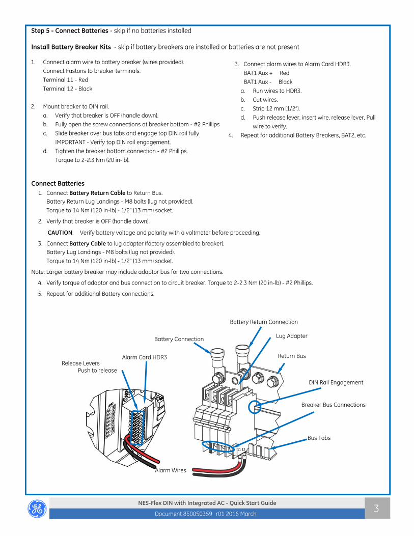
Step 5 - Connect Batteries - skip if no batteries installed Install Battery Breaker Kits - skip if battery breakers are installed or batteries are not present
Connect Batteries 1. Connect Battery Return Cable to Return Bus.
Battery Return Lug Landings - M8 bolts (lug not provided).
Torque to 14 Nm (120 in-lb) - 1/2” (13 mm) socket.
2. Verify that breaker is OFF (handle down).
CAUTION: Verify battery voltage and polarity with a voltmeter before proceeding.
3. Connect Battery Cable to lug adapter (factory assembled to breaker). Battery Lug Landings - M8 bolts (lug not provided).
Torque to 14 Nm (120 in-lb) - 1/2” (13 mm) socket.
Note: Larger battery breaker may include adaptor bus for two connections.
4. Verify torque of adaptor and bus connection to circuit breaker. Torque to 2-2.3 Nm (20 in-lb) - #2 Phillips.
5. Repeat for additional Battery connections.
1. Connect alarm wire to battery breaker (wires provided).
Connect Fastons to breaker terminals.
Terminal 11 - Red
Terminal 12 - Black
2. Mount breaker to DIN rail.
a. Verify that breaker is OFF (handle down).
b. Fully open the screw connections at breaker bottom - #2 Phillips
c. Slide breaker over bus tabs and engage top DIN rail fully
IMPORTANT - Verify top DIN rail engagement.
d. Tighten the breaker bottom connection - #2 Phillips.
Torque to 2-2.3 Nm (20 in-lb).
3. Connect alarm wires to Alarm Card HDR3.
BAT1 Aux + Red
BAT1 Aux - Black
a. Run wires to HDR3.
b. Cut wires.
c. Strip 12 mm (1/2”).
d. Push release lever, insert wire, release lever, Pull
wire to verify.
4. Repeat for additional Battery Breakers, BAT2, etc.
Battery Return Connection
Release Levers Push to release
11 12
Breaker Bus Connections
Lug Adapter Battery Connection
Return Bus
Alarm Wires
Bus Tabs
Alarm Card HDR3
DIN Rail Engagement

NES-Flex DIN with Integrated AC - Quick Start Guide
Document 850050359 r01 2016 March 4
Step 6 - Connect Loads (Outputs) For system with LVLD (two shelf system only), note positions of priority (critical) versus non-priority (non-critical) loads. There can be up to 6 priority and 9 non-priority loads.
1. Verify that breaker is OFF (handle down).
2. Mount breaker to DIN rail.
a. Fully open the connection at breaker bottom - #2 Phillips.
b. Slide breaker over bus tab and fully engage top DIN rail.
IMPORTANT—Verify top DIN rail engagement. a. Tighten the breaker bottom connection - #2 Phillips.
Hold firmly downward and torque to 2-2.3 Nm (20 in-lb).
3. Connect alarm wire to load breaker. Note: This wire will be secured to the breaker along side the load wire.
a. Fully open the screw connection at breaker top - #2 Phillips.
b. Choose any wire from the bundle of black wires behind the breakers. Cut wire. Strip 10 mm (3/8”). Insert wire into breaker load connection. Do not tighten the breaker connection.
4. Repeat for additional Load Breakers.
Connect Loads (Outputs)
1. Connect load return wire to the Load Return Bus - M6 lug (not provided).
2. Connect load wire to breaker.
a. Strip load wire to 10 mm (3/8”).
b. Insert load wire into breaker load wire connection alongside the alarm wire.
c. Tighten the breaker top screw connection - #2 Phillips; torque to 2-2.3 Nm (20 in-lb). Assure both the load wire and the alarm wire are secured.
d. Verify torque of circuit breaker bus connection - #2 Phillips: torque to 2-2.3 Nm (20 in-lb).
3. Repeat for additional loads.
ID Label Example
Step 8 - Connect Controller Cables For additional details, see Steps 11 and 12 for controller infor-mation, and Information Sections on battery monitoring and alarm connections. 1. Connect LAN (10Base-T Ethernet) Communication. 2. Connect 1-Wire Battery Monitoring Cables.
3. Connect alarm input and output cables.
Return Bus
Breaker Load Connection
Screw
Breaker Bus Connection
Screw
DIN Rail Engagement
Bus Tabs
Load Return Connection
Load Wire
Alarm wire: secure with the load wire
Step 7 - Label Connections ID label is in front of the breakers or on the door.
Mark each connected circuit identification on the ID label.
Alarm Inputs LAN Alarm Outputs
Thermal Probes
Controller
Alarm Relay Jumpers

NES-Flex DIN with Integrated AC - Quick Start Guide
Document 850050359 r01 2016 March 5
Craft Port behind door
Step 9 - Install Rectifiers
Caution: Make sure the AC breakers are off. Caution: The rectifier latch is not a carrying handle.
Step 10 - Initial Start Up
Bring Rectifiers Online: 1. Verify the AC and DC connections are complete and secure.
2. Turn on AC input breakers.
Bring Batteries Online:
3. Measure voltage of all battery strings.
4. Set float voltage in controller to lowest measured valid string voltage.
5. Turn on battery breaker of any battery string within 1/2 volt of this lowest measured voltage.
6. Continue by adjusting system voltage up to next measured string not on-line.
Repeat process 5 and 6 until all battery strings are on-line.
7. As batteries charge gradually increase float voltage in controller to desired float voltage.
8. Check Controller for alarms and make required adjustments to default settings for this installation.
Step 11 - Configure Controller
Notes: 1. The Pulsar Plus Controller Family Product Manual includes additional information.
2. This system automatically configures Rectifier Parameters.
View and Change Parameters and Alarm Severity
View and change system parameters from the factory defaults via a. Controller Display
b. Craft Port on front of controller using a laptop with EasyView2 software or HyperTerminal.
EasyView2 (GUI) software can be downloaded from www.gecriticalpower.com,
c. J5 LAN port web pages using a laptop with browser. LAN port Server mode is for local laptop connection. Set the LAN port to Server:
With the controller set to Server enter the default IP address 192.168.2.1 (default) in the web browser address field.
Warning: Do not connect J5 LAN port to a network when set to Server. Set the controller to Client or Static before connecting to the network. Static is the factory default setting and the typical setting for most networks.
LAN Port - Local / Network
The LAN port is be configured as Local or Network - controller display menu path: Configuration > Communication Ports > Network Settings > DHCP > mode CLIENT or SERVER
Local (Server): LAN connects to a laptop. Local (Server) is a temporary setting. When configuration is complete, return LAN port to Network (Client) mode.
Network (Client): LAN connects to a network. (Default).
CAUTION: Do not connect LAN port to a network when configured as Local.
Slide the unit into the power slot approxi-mately 3/4 of the way.
Open the faceplate by sliding the faceplate latch to the left until the faceplate releases and swings outward.
Slide the unit into the slot until it engages with the back of the shelf. Swing the face-plate closed to fully seat the rectifier. Verify the faceplate is latched.

NES-Flex DIN with Integrated AC - Quick Start Guide
Document 850050359 r01 2016 March 6
Front Display
Craft Port behind door
Plant Status LEDs
Voltage Test Jacks LCD Display Menu Navigation
Front Display Menu Map
Step 12 - Controller Basic Operation
Controller Alarm Status: The display changes colors; Green = Normal, Amber = Minor Alarm, Red = Critical/Major Alarm
Some alarms may occur during initial installation; example: thermal probe fail or Major/Minor communication fail. Clear these alarms: Via Controller Display: follow the menu path; Menu > Control/Operation > Clear Events or Uninstall Equipment. Via web pages or EasyView2; Select the Maintenance tab > clear latched events and clear missing devices.
Verify Basic Installation Settings: Date, Time, Battery Type, number of strings and float voltage Controller Display - Menu > Configuration > System Settings and Menu > Configuration > Batteries. Web pages or EasyView2 - Installation Tab for Date, Time. Site ID and Site Description. Settings Tab > Battery Management for Battery Type and number of battery strings installed.
Web Home Page
Step 11 - Configure Controller (continued)
Alarm Relay Jumpers and 1-Wire Data reference
Jumpers are located on the top of the controller.
Alarm Relay Jumper Factory Defaults are Open On Alarm
1-Wire Reference Factory Default is -48V.

NES-Flex DIN with Integrated AC - Quick Start Guide
Document 850050359 r01 2016 March 7
Information: Battery Monitoring Connections
Battery Monitoring is accomplished with a “Daisy Chained” series of probes. The Probes monitor battery temperature and voltage (ES771 required to monitor voltage). Bolt the Probe under the “–“ terminal connector hardware; NOT under the connecting lug.
Max per system: Probes - 16, ES771 Modules - 6.
Battery Temperature Measurement
Ordering Codes Descriptions Ordering Codes Descriptions
CC109142980 QS873A Battery Thermal Probe 108958422 ES771A Voltage Monitor Card
150026698 QS873B Ambient Probe CC848791517 D 2 ½’ ES771A to probe wireset
CC848817024 B 10’ controller to thermal probe wireset CC848797290 D 6’ ES771A to probe wireset
CC109157434 B 20’ controller to thermal probe wireset 848719829 D 10’ ES771A to probe wireset
CC848822560 C 1’ thermal probe to thermal probe wireset CC848791500 G 4’ ES771A to ES771A or controller wireset
848719803 C 5’ thermal probe to thermal probe wireset 848652947 G 10’ ES771A to ES771A or controller wireset
850037334 C 20’ thermal probe to thermal probe wireset
Battery Temperature and Voltage Measurement
Information: Alarm Connections
Alarm Output Cables Alarm Input Cables
CC848890137 5 ft. CC848890153 5 ft.
CC109157442 15ft CC848865980 15 ft.
CC848817635 50 ft CC848817651 50 ft.
CC848817643 150 ft CC848817668 150 ft.
Alarm Outputs Alarm relays are factory set to Open On Alarm. If Close On Alarm is desired adjust controller alarm jumpers. See diagram in step 8 for the location of the controller alarm jumpers. Alarm output is a 20-pin latching connector. Alarm relays can be assigned as desired.
Alarm Inputs Default alarm descriptions may be changed as needed using web pages or Easyview2. Alarm input is a 10-pin latching connector.
Standard Controller Alarm Input Defaults
J3 Pin Color
Air Con Fail 1 BK
Air Con Fail_Return 8 V
Door Open 2 BR
Door Open_Return 8 V
Aux PMJ Input 3 R
Battery Test/GSTR 4 O
Battery Test_Return 9 S
EPO 5 Y
EPO_Return 10 W
Hi ext. Temp. 6 G
Hi ext. Temp._Return 8 V
Low ext. Temp. 7 BL
Low ext. Temp._Return 8 V
Standard Controller Alarm Output Defaults Pin Color Option 1
Color Option 2
PCR Power Critical 1 BL BL PCR_C Power Critical_C 11 W BL/BK PMJ Power Major 2 O O PMJ_C Power Major_C 12 W O/BK PMN Power Minor 3 G G PMN_C Power Minor_C 13 W G/BK R1 Battery On Discharge 4 BR W R1_C Battery On Discharge_C (BD_C) 14 W W/BK R2 Very Low Voltage (VLV) 5 S BK R2_C Very Low Voltage_C (VLV_C) 15 W BK/W R3 Fuse Alarm Major (FAJ) 6 BL BL/W R3_C Fuse Alarm Major_C (FAJ_C) 16 R BL/R R4 AC Fail (ACF) 7 O O/R R4_C AC Fail_C (ACF_C) 17 R R R5 Rectifier Fail (RFA) 8 G G/W R5_C Rectifier Fail_C (RFA_C) 18 R R/G R6 Mult. Rectifier Fail (MRFA) 9 BR W/R R6_C Mult. Rectifier Fail_C (MRFA_C) 19 R R/W R7 High Voltage (HV) 10 S BK/R R7_C High Voltage_C (HV_C) 20 R R/BK

NES-Flex DIN with Integrated AC - Quick Start Guide
Document 850050359 r01 2016 March 8
Information: Rectifier Options
Information: Clear Breaker Alarm
The Alarm Card monitors all breakers that were once ON.
Breaker Alarms occur while breakers are OFF or TRIPPED.
Clear Breaker Alarm Turn the breaker ON or Press the Alarm Reset button to ignore all breakers that are OFF or TRIPPED, until they are again ON.
Alarm Reset
Information: Surge Protectors Surge Protection Device consists of three RU-320-25 field-replaceable modules protecting Line to Neutral and one RU-180-25 field-replaceable module protecting Neutral to Ground. Replace pluggable modules if RED indicator tab is visible on any of the multiple pole units. To remove:
1. Verify that you have the correct replacement module. 2. Disconnect power. 3. Pull the pluggable module from the base. 4. Push a new pluggable module into the base. You will hear a “click”, indicating that the module is set in place. An insertion “key”
built into the unit will help ensure that the module has been correctly selected.
CAUTION: Use of excessive force, during insertion, can result in damage to the module or the base.
Rectifier Input Output 48Vdc
Recommended 3-phase AC Breaker (PH-N) “WYE”
1-shelf (3 rectifiers)
AC Breaker/Wire Gauge
2-shelf (6 rectifiers)
AC Breaker/Wire Gauge
Eco Rectifier
blue
NE050ECO48ATEZ ac 200-277 Vac 50A 20A /12 AWG 40A / 8 AWG
Rectifier
blue
NE075AC48ATEZ ac 200-277 Vac 75A 30A / 10 AWG 50A / 8 AWG
NE050AC48ATEZ ac 208-277 Vac 50A 20A / 12 AWG 40A / 8 AWG
Surge Protectors Red Indicator Window
L1 L2 L3 G
N

NES-Flex DIN with Integrated AC - Quick Start Guide
Document 850050359 r01 2016 March 9
Safety Statements Do not install this equipment over combustible surfaces.
Rules and Regulations - Follow all national and local rules and regulations when making field connections.
Compression Connectors
U. S. or Canada installations - use Listed/Certified compression connectors to terminate Listed/Certified field-wire conductors.
All installations - apply the appropriate connector to the correct size conductor as specified by the connector manufacturer, using only the connector manufacturer’s recommended or approved tooling for that connector.
Electrical Connection Securing: Torque to the values specified on labels or in the product documentation.
Cable Dress - dress to avoid damage to the conductors and undue stress on the connectors.
Circuit Breakers and Fuses
Use only those specified in the equipment ordering guide.
Size as required by the National Electric Code (NEC) and/or local codes. Safety Tested Limits - Refer to the equipment ratings to assure current does not exceed: Continuous Load (List 1) - 60% of protector rating Maximum Load (List 2 - typically end of discharge) - 80% of protector rating.
GMT Style Fuses - Use only fuses provided with safety caps. Field-wired Conductors - Follow all National Electric Code (NEC) and local rules and regulations.
Insulation rating: 90°C minimum; 105°C (minimum) if internal to enclosed equipment cabinets.
Size AC field-wired conductors with 75°C ampacity (NEC) equal to or greater than their panel board circuit breaker rating.
Size DC field-wired conductors with 90°C ampacity (NEC) equal to or greater than circuit breaker/fuse rating.
AC and DC input disconnect/protection - Provide accessible devices to remove input power in an emergency.
Alarm Signals - Provide external current limiting protection. Rating 60V, 0.5A unless otherwise noted.
Grounding - Connect the equipment chassis directly to ground. In enclosed equipment cabinets connect to the cabinet AC service ground bus. In huts, vaults, and central offices connect to the system bonding network.
Specifications and Application Specifications and ordering information are in the brochures listed in Reference Documents.
Equipment and subassembly ports: 1. are suitable for connection to intra-building or unexposed wiring or cabling; 2. can be connected to shielded intra-building cabling grounded at both ends.
Grounding / Bonding Network – Connect to an Isolated Ground Plane (Isolated Bonding Network) or an Integrated Ground Plane (Mesh-Bonding Network or Common Bonding Network).
Installation Environment - Install in Network Telecommunication Facilities, OSP, or where NEC applies.
Battery return may be either Isolated DC return (DC-I) or Common DC return (DC-C).
Reference Documents These documents are available at www.gecriticalpower.com.
Document Title CC848815341 Galaxy Pulsar Plus Product Manual Infinity S (NE S) Brochure

NES-Flex DIN with Integrated AC - Quick Start Guide
Document 850050359 r01 2016 March 10
Precautions Install, service, and operate equipment only by professional, skilled and qualified personnel who have the necessary knowledge and
practical experience with electrical equipment and who understand the hazards that can arise when working on this type of equipment.
Disconnect batteries from outputs and/or follow safety procedures while working on equipment. Batteries may be connected in parallel with the output of the rectifiers. Turning off the rectifiers will not necessarily remove power from the bus.
Do not disconnect permanent bonding connections unless all power inputs are disconnected.
Verify that equipment is properly safety earth grounded before connecting power. High leakage currents may be possible.
Exercise care and follow all safety warnings and practices when servicing this equipment. Hazardous energy and voltages are present in the unit and on the interface cables that can shock or cause serious injury. When equipped with ringer modules, hazardous voltages will be present on the ringer output connectors.
Use the following precautions in addition to proper job training and safety procedures:
Use only properly insulated tools.
Remove all metallic objects (key chains, glasses, rings, watches, or other jewelry).
Follow Lock Out Tag Out (LOTO) procedures: customer specified, site specific, or general as appropriate. Disconnect all power input before servicing the equipment. Check for multiple power inputs.
Wear safety glasses.
Follow Personal Protective Equipment requirements: customer specified, site specific, or general as appropriate.
Test circuits before touching.
Be aware of potential hazards before servicing equipment.
Identify exposed hazardous electrical potentials on connectors, wiring, etc.
Avoid contacting circuits when removing or replacing covers;.
Use a personal ESD strap when accessing or removing electronic components.
Personnel with electronic medical devices need to be aware that proximity to DC power and distribution systems, including batteries and cables, typically found in telecommunications utility rooms, can affect medical electronic devices, such as pacemakers. Effects decrease with distance.

NES-Flex DIN with Integrated AC - Quick Start Guide
Document 850050359 r01 2016 March 11
Notes

NES-Flex DIN with Integrated AC - Quick Start Guide
Document 850050359 r01 2016 March 12 GE ● 601 Shiloh Rd. ● Plano, TX 75074 ● 1- 877-546-3243 ● Outside U.S.A. 1-972-244-9288
www.gecriticalpower.com © 2016 General Electric Company. All rights reserved.
Notes