CP1W-CIF41 de W462-E1-06
46
551 SECTION 9 Ethernet Option Board This section gives an outline of the Ethernet Option Board, explains how to install and remove the Ethernet Option Board, and how to monitor and make settings required for operation. It also lists the errors during operation and provides countermeasures for troubleshooting. 9-1 Ethernet Option Board Function Guide . . . . . . . . . . . . . . . . . . . . . . . . . . . . . 552 9-1-1 Overall system configuration example . . . . . . . . . . . . . . . . . . . . . . . 552 9-1-2 Connecting the CX-Programmer to PLCs Online via Ethernet . . . . 553 9-1-3 Receiving Data from OMRON PLCs using Ethernet . . . . . . . . . . . . 554 9-2 Differential Monitoring . . . . . . . . . . . . . . . . . . . . . . . . . . . . . . . . . . . . . . . . . . 555 9-3 System Configuration . . . . . . . . . . . . . . . . . . . . . . . . . . . . . . . . . . . . . . . . . . . 556 9-3-1 System Configuration . . . . . . . . . . . . . . . . . . . . . . . . . . . . . . . . . . . . 556 9-3-2 Devices Required for Constructing a Network . . . . . . . . . . . . . . . . . 556 9-4 Specifications . . . . . . . . . . . . . . . . . . . . . . . . . . . . . . . . . . . . . . . . . . . . . . . . . 557 9-5 FINS Communications . . . . . . . . . . . . . . . . . . . . . . . . . . . . . . . . . . . . . . . . . . 558 9-5-1 FINS Communications Service Specifications . . . . . . . . . . . . . . . . . 558 9-5-2 Overview of FINS Communication Service . . . . . . . . . . . . . . . . . . . 559 9-6 Part Names . . . . . . . . . . . . . . . . . . . . . . . . . . . . . . . . . . . . . . . . . . . . . . . . . . . 560 9-7 Comparison with Previous Models . . . . . . . . . . . . . . . . . . . . . . . . . . . . . . . . . 561 9-8 Installation and Initial Setup . . . . . . . . . . . . . . . . . . . . . . . . . . . . . . . . . . . . . . 562 9-8-1 Overview of Startup Procedure. . . . . . . . . . . . . . . . . . . . . . . . . . . . . 562 9-8-2 Installation and Removing . . . . . . . . . . . . . . . . . . . . . . . . . . . . . . . . 563 9-8-3 Network Installation . . . . . . . . . . . . . . . . . . . . . . . . . . . . . . . . . . . . . 564 9-8-4 Web Browser Setting Function . . . . . . . . . . . . . . . . . . . . . . . . . . . . . 567 9-9 Memory Allocations . . . . . . . . . . . . . . . . . . . . . . . . . . . . . . . . . . . . . . . . . . . . 569 9-9-1 CIO Area Allocation . . . . . . . . . . . . . . . . . . . . . . . . . . . . . . . . . . . . . 569 9-9-2 DM Area Allocation . . . . . . . . . . . . . . . . . . . . . . . . . . . . . . . . . . . . . 571 9-10 Web Browser Setup and Display. . . . . . . . . . . . . . . . . . . . . . . . . . . . . . . . . . . 575 9-10-1 Multi-language Function . . . . . . . . . . . . . . . . . . . . . . . . . . . . . . . . . 575 9-10-2 Overview of Web Browser Function . . . . . . . . . . . . . . . . . . . . . . . . 575 9-10-3 System. . . . . . . . . . . . . . . . . . . . . . . . . . . . . . . . . . . . . . . . . . . . . . . . 576 9-10-4 HTTP . . . . . . . . . . . . . . . . . . . . . . . . . . . . . . . . . . . . . . . . . . . . . . . . 578 9-10-5 IP Address Table . . . . . . . . . . . . . . . . . . . . . . . . . . . . . . . . . . . . . . . . 579 9-10-6 IP Router Table . . . . . . . . . . . . . . . . . . . . . . . . . . . . . . . . . . . . . . . . . 580 9-10-7 FINS/TCP . . . . . . . . . . . . . . . . . . . . . . . . . . . . . . . . . . . . . . . . . . . . . 581 9-10-8 Unit Information . . . . . . . . . . . . . . . . . . . . . . . . . . . . . . . . . . . . . . . . 582 9-10-9 Unit Status . . . . . . . . . . . . . . . . . . . . . . . . . . . . . . . . . . . . . . . . . . . . 583 9-10-10 FINS Status . . . . . . . . . . . . . . . . . . . . . . . . . . . . . . . . . . . . . . . . . . . . 584 9-10-11 Error Log . . . . . . . . . . . . . . . . . . . . . . . . . . . . . . . . . . . . . . . . . . . . . 585 9-11 Trouble Shooting . . . . . . . . . . . . . . . . . . . . . . . . . . . . . . . . . . . . . . . . . . . . . . . 586 9-11-1 Error Log . . . . . . . . . . . . . . . . . . . . . . . . . . . . . . . . . . . . . . . . . . . . . 586 9-11-2 Trouble-shooting with Indicators and Error Code Display . . . . . . . 589 9-11-3 Error Status . . . . . . . . . . . . . . . . . . . . . . . . . . . . . . . . . . . . . . . . . . . . 590 9-12 Sample Application . . . . . . . . . . . . . . . . . . . . . . . . . . . . . . . . . . . . . . . . . . . . . 591
-
Upload
viet-huynh-quoc -
Category
Documents
-
view
555 -
download
10
Transcript of CP1W-CIF41 de W462-E1-06

551
SECTION 9Ethernet Option Board
This section gives an outline of the Ethernet Option Board, explains how to install and remove the Ethernet Option Board,and how to monitor and make settings required for operation. It also lists the errors during operation and providescountermeasures for troubleshooting.
9-1 Ethernet Option Board Function Guide . . . . . . . . . . . . . . . . . . . . . . . . . . . . . 552
9-1-1 Overall system configuration example . . . . . . . . . . . . . . . . . . . . . . . 552
9-1-2 Connecting the CX-Programmer to PLCs Online via Ethernet . . . . 553
9-1-3 Receiving Data from OMRON PLCs using Ethernet . . . . . . . . . . . . 554
9-2 Differential Monitoring . . . . . . . . . . . . . . . . . . . . . . . . . . . . . . . . . . . . . . . . . . 555
9-3 System Configuration . . . . . . . . . . . . . . . . . . . . . . . . . . . . . . . . . . . . . . . . . . . 556
9-3-1 System Configuration . . . . . . . . . . . . . . . . . . . . . . . . . . . . . . . . . . . . 556
9-3-2 Devices Required for Constructing a Network. . . . . . . . . . . . . . . . . 556
9-4 Specifications . . . . . . . . . . . . . . . . . . . . . . . . . . . . . . . . . . . . . . . . . . . . . . . . . 557
9-5 FINS Communications . . . . . . . . . . . . . . . . . . . . . . . . . . . . . . . . . . . . . . . . . . 558
9-5-1 FINS Communications Service Specifications. . . . . . . . . . . . . . . . . 558
9-5-2 Overview of FINS Communication Service . . . . . . . . . . . . . . . . . . . 559
9-6 Part Names . . . . . . . . . . . . . . . . . . . . . . . . . . . . . . . . . . . . . . . . . . . . . . . . . . . 560
9-7 Comparison with Previous Models . . . . . . . . . . . . . . . . . . . . . . . . . . . . . . . . . 561
9-8 Installation and Initial Setup . . . . . . . . . . . . . . . . . . . . . . . . . . . . . . . . . . . . . . 562
9-8-1 Overview of Startup Procedure. . . . . . . . . . . . . . . . . . . . . . . . . . . . . 562
9-8-2 Installation and Removing . . . . . . . . . . . . . . . . . . . . . . . . . . . . . . . . 563
9-8-3 Network Installation . . . . . . . . . . . . . . . . . . . . . . . . . . . . . . . . . . . . . 564
9-8-4 Web Browser Setting Function . . . . . . . . . . . . . . . . . . . . . . . . . . . . . 567
9-9 Memory Allocations . . . . . . . . . . . . . . . . . . . . . . . . . . . . . . . . . . . . . . . . . . . . 569
9-9-1 CIO Area Allocation. . . . . . . . . . . . . . . . . . . . . . . . . . . . . . . . . . . . . 569
9-9-2 DM Area Allocation . . . . . . . . . . . . . . . . . . . . . . . . . . . . . . . . . . . . . 571
9-10 Web Browser Setup and Display. . . . . . . . . . . . . . . . . . . . . . . . . . . . . . . . . . . 575
9-10-1 Multi-language Function . . . . . . . . . . . . . . . . . . . . . . . . . . . . . . . . . 575
9-10-2 Overview of Web Browser Function . . . . . . . . . . . . . . . . . . . . . . . . 575
9-10-3 System. . . . . . . . . . . . . . . . . . . . . . . . . . . . . . . . . . . . . . . . . . . . . . . . 576
9-10-4 HTTP . . . . . . . . . . . . . . . . . . . . . . . . . . . . . . . . . . . . . . . . . . . . . . . . 578
9-10-5 IP Address Table. . . . . . . . . . . . . . . . . . . . . . . . . . . . . . . . . . . . . . . . 579
9-10-6 IP Router Table . . . . . . . . . . . . . . . . . . . . . . . . . . . . . . . . . . . . . . . . . 580
9-10-7 FINS/TCP . . . . . . . . . . . . . . . . . . . . . . . . . . . . . . . . . . . . . . . . . . . . . 581
9-10-8 Unit Information . . . . . . . . . . . . . . . . . . . . . . . . . . . . . . . . . . . . . . . . 582
9-10-9 Unit Status . . . . . . . . . . . . . . . . . . . . . . . . . . . . . . . . . . . . . . . . . . . . 583
9-10-10 FINS Status. . . . . . . . . . . . . . . . . . . . . . . . . . . . . . . . . . . . . . . . . . . . 584
9-10-11 Error Log . . . . . . . . . . . . . . . . . . . . . . . . . . . . . . . . . . . . . . . . . . . . . 585
9-11 Trouble Shooting. . . . . . . . . . . . . . . . . . . . . . . . . . . . . . . . . . . . . . . . . . . . . . . 586
9-11-1 Error Log . . . . . . . . . . . . . . . . . . . . . . . . . . . . . . . . . . . . . . . . . . . . . 586
9-11-2 Trouble-shooting with Indicators and Error Code Display . . . . . . . 589
9-11-3 Error Status . . . . . . . . . . . . . . . . . . . . . . . . . . . . . . . . . . . . . . . . . . . . 590
9-12 Sample Application. . . . . . . . . . . . . . . . . . . . . . . . . . . . . . . . . . . . . . . . . . . . . 591

552
Ethernet Option Board Function Guide Section 9-1
9-1 Ethernet Option Board Function Guide
9-1-1 Overall system configuration exampleEthernet Option Board provides receiving commands by OMRON standardprotocol FINS for CP1L and CP1H programmable controllers. The EthernetNetwork Interface allows you to easily connect CP1L and CP1H Programma-ble Controllers onto new or existing Ethernet network and upload/downloadprograms, communicate between controllers (do not support real-time scan-ning I/O on Ethernet Option Board).
Note 1. Please use CX-Programmer version 8.1 or higher (CX-ONE version 3.1 or higher).
2. Please use CX-Integrator version 2.33 or higher (CX-ONE version 3.1 or higher) to make therouting table. Except making the routing table for CP1W-CIF41, other functions, such as trans-ferring the parameters and network structure, are not supported by CX-Integrator.
3. Use the Web browser to set the CP1W-CIF41.
4. NS-series HMI version 8.2 or higher can use CP1W-CIF41 through Ethernet.
Connecting through multiple segments, such as over the Internet: Use FINS/TCP.
FINS
Internet
IP router
Firewall(Server room)
Intranet
(Office floor)
CX-Programmer
FINS
EthernetEthernetRouter
(Production line)
Ethernet
PLC PLC
Ethernet Option Board Ethernet Option Board
Connecting within the same segment: Use FINS/UDP.
Wireless
FINS
Using media with unreliable connections, such as wireless LAN: Use FINS/TCP.
FINS
NS-series PT
FINS
Router

553
Ethernet Option Board Function Guide Section 9-1
9-1-2 Connecting the CX-Programmer to PLCs Online via EthernetConnecting within the Same Segment
Use the UDP/IP version of the FINS communications service (i.e.,FINS/UDP). FINS/UDP is supported by many OMRON products and is com-patible with earlier Ethernet Units (CS1W-ETN01/ETN11/ETN21 and CJ1W-ETN11/ETN21). The CX-Programmer can be connected and used withFINS/UDP.
Connecting through Multiple Segments
Use the TCP/IP version of the FINS communications service (i.e., FINS/TCP).It provides automatic recovery at the TCP/IP layer from communicationserrors (such as packet loss) that occur during multilevel routing. For CX-Pro-grammer, FINS/TCP can be used to directly connect to the PLC online.
Using Media with Unreliable Connections, Such as a Wireless LAN
Use the TCP/IP version of the FINS communications service (i.e., FINS/TCP).It provides automatic recovery at the TCP/IP layer from communicationserrors (such as packet loss) resulting from unreliable connections. For CX-Programmer, FINS/TCP can be used to directly connect to the PLC online.
Connecting from a Personal Computer with a Dynamic Private IP Address
Depending on whether or not the connection will be within the same segment,either use an IP address conversion method for dynamic IP addresses in theUDP/IP version of the FINS communications service or use the TCP/IP ver-sion of the FINS communications service.
It is possible to connect online to a PLC using the CX-Programmer from acomputer serving as a temporarily connected node or a permanent DHCP cli-ent.
For CX-Programmer, FINS/TCP can be used to directly connect to the PLConline.
Connecting through multiple segments, such as over the Internet: Use FINS/TCP.
FINS
Internet
IP router
FirewallIntranet
(Office floor)
CX-Programmer
FINS
EthernetEthernetRouter
(Production line)
Ethernet
Connecting within the same segment: Use FINS/UDP.
PLCPLC Wireless
FINS
Using media with unreliable connections, such as wireless LAN: Use FINS/TCP.
FINS
Connecting from a computer with a dynamic private IP address: Use FINS/TCP or FINS/UDP.
CX-Programmer
CX-Programmer
Ethernet Option Board Ethernet Option Board
CX-Programmer
Router

554
Ethernet Option Board Function Guide Section 9-1
9-1-3 Receiving Data from OMRON PLCs using EthernetThe CP1W-CIF41 Ethernet Option Board can only support receiving FINScommands from OMRON PLCs using Ethernet.
Connecting within the Same Segment
Use the UDP/IP version of the FINS communications service (i.e.,FINS/UDP), and construct applications using the SEND(090), RECV(098),and CMND(490) instructions in the ladder program. FINS/UDP is supportedby many OMRON products, and is compatible with earlier Ethernet Units(CS1W-ETN01/ETN11/ETN21 and CJ1W-ETN11/ETN21). The protocol pro-cessing for FINS/UDP is simpler than for FINS/TCP, giving FINS/UDP certainadvantages in terms of performance. Another feature of FINS/UDP is that itcan be used for broadcasting.
On the other hand, with FINS/UDP it is necessary to provide measures, suchas retries, for handling communications errors.
Connecting through Multiple Segments
Use the TCP/IP version of the FINS communications service (i.e., FINS/TCP),and construct applications using the SEND(090), RECV(098), andCMND(490) instructions in the ladder program. FINS/TCP is the initial func-tion supported by this Ethernet Option Board (CP1W-CIF41). It provides auto-matic recovery at the TCP/IP layer from communications errors (such aspacket loss) that occur during multilevel routing.
Intranet
Production line A
Ethernet Unit
EthernetRouter
FINS message communications
Connecting through multiple segments: Use FINS/TCP.
Production line BRouter
Ethernet Option Board Ethernet Option Board
Only receiving FINS commands via Ethernet from OMRON PLCs
PLCPLC

555
Differential Monitoring Section 9-2
9-2 Differential Monitoring
Compatibility and SpeedThe transmission medium of Ethernet side has been upgraded to 100Base-TX, while compatibility with some functions and application interfaces of theexisting Ethernet Unit models for CS/CJ series has been maintained.
Limited by the Toolbus protocol used on the serial side, the processing speedis only 115.2kbps, slower than the existing Ethernet Unit. The FINS framelength is less than 1,004 bytes, so the system response performance for thesame FINS message applications is longer than the existing Ethernet Unit.
Various Protocols Available on EthernetA variety of protocols make a wide range of applications for use on an Ether-net network. The protocols that can be selected include receiving commandsby OMRON’s standard protocol FINS and reading Ethernet Option Board set-tings and status by HTTP.
A communications service can be selected according to need, allowing thePLC to be flexibly integrated with the Ethernet information network.
Improved FINS Message CommunicationsThe following functions have been maintained according to the existing Ether-net Unit models for CS/CJ series.
• The maximum number of nodes is 254.
• Communications are enabled even if the host computer’s IP address isdynamic.
• An automatic client FINS node address allocation function makes it possi-ble to connect online to the PLC even if no FINS node address has beenset for the host computer.
• FINS message communications are enabled in both UDP/IP and TCP/IP,but it are only enabled in TCP/IP with up to 2 simultaneous connections .→Previously it are enabled in TCP/IP with up to 16 simultaneous connec-tions and all can be set to client.
• Multiple FINS applications, such as the CX-Programmer, on the samecomputer can be connected online to the PLC via Ethernet.
Use Web Function to Read Ethernet Option Board Settings and StatusA Web function is provided in Ethernet Option Board.
This enables use of a Web browser to read the Ethernet Option Board’s sys-tem settings and statuses.
Full Range of Functions for Handling TroublesA full range of functions is provided for promptly handling any troubles.
• Self-diagnostic function when power is turned ON.
• Error log for recording error information when an error occurs.

556
System Configuration Section 9-3
9-3 System Configuration
9-3-1 System Configuration
9-3-2 Devices Required for Constructing a NetworkThe basic configuration for a 100Base-TX Ethernet System consists of onehub to which nodes are attached in star form using twisted-pair cable. Thedevices shown in the following table are required to configure a network with100Base-TX-type CP1W-CIF41, so prepared them in advance.
Recommended Hubs For detail on recommended devices for constructing a network, refer to 9-8-3
Network Installation.
(3) HubCX-Programmer CX-Integrator
(2) Twisted pair cable
(1) CP1W-CIF41
CP1L/CP1H Series PLC
Network device Contents
(1) Ethernet Option Board (CP1W-CIF41)
The Ethernet Option Board is a Communication Unit that connects a CP1H series or CP1L series PLC to 100Base-TX Ethernet networks. (They can also be used as 10Base-T.)
(2) Twisted-pair cable This is twisted-pair cable for connecting 100Base-TX type Ethernet Option Board to the hub, with an RJ45 Modular Connector at each end.Use a category 3, 4, 5, or 5e UTP (unshielded twisted pair) or STP (shielded twisted-pair) cable.
(3) Hub This is a relay device for connecting multiple nodes in a star LAN.

557
Specifications Section 9-4
9-4 Specifications
Note If two CP1W-CIF41 Ethernet Option Boards are mounted in the CP1L/H system, the CP1W-CIF41 mounted on option board slot 1 will be abnormal and ERR indicator will be ON, the CP1W-CIF41 on option board slot 2 will work normally.
Item Specifications
Model number CP1W-CIF41
Type 100/10Base-TX (Auto-MDIX)
Applicable PLCs CP1L and CP1H PLCs
Unit classification CP1 option port unit
Mounting location CP1L and CP1H micro PLC option port
Number of Units that can be
mounted
1 set. (each type of CP1L and CP1H PLC can only mount 1 set Ethernet Option Board)
(See note.)
Size of Buffers 8K bytes
Transfer Media access method CSMA/CD
Modulation method Baseband
Transmission paths Star form
Baud rate 100 Mbit/s (100Base-TX) 10 Mbit/s (10Base-T)
• Half/full auto-negotiation for each port• Link speed auto-sensing for each port
Transmission media • Unshielded twisted-pair (UDP) cable
Categories: 5, 5e • Shielded twisted-pair (STP) cable
Categories: 100Ω at 5, 5e
• Unshielded twisted-pair (UDP) cable
Categories: 3, 4, 5, 5e • Shielded twisted-pair (STP) cable
Categories: 100Ω at 3, 4, 5, 5e Transmission Distance 100 m (distance between hub and node)
Current consumption (Unit) 130 mA max. at 5 V DC
Vibration resistance Conforms to JIS 0040.
10 to 57Hz: 0.075-mm amplitude, 57 to 150 Hz: acceleration 9.8 m/s2 in X, Y, and Z directions for 80 minutes each (sweep time: 8 minutes×10 sweeps = 80 minutes)
Shock resistance Conforms to JIS 0041.
147m/s2, 3 times each in X, Y, and Z directions
Ambient operating temperature 0 to 55°C
Ambient humidity 10% to 90% (with no condensation)
Atmosphere Must be free of corrosive gas.
Ambient storage temperature -20 to 75°C
Weight 23 g max.
Dimensions 36.4×36.4×28.2 mm (W×H×D)

558
FINS Communications Section 9-5
9-5 FINS Communications
9-5-1 FINS Communications Service Specifications
Note Refer to the following diagram for the relation between message length and date length.
Item Specification
Number of nodes 254
Message Length 1016 bytes max.
Date Length 1004 bytes max. (See note)
Number of buffer 14 (1016 bytes×6+240 bytes×8)
Protocol name FINS/UDP method FINS/TCP method
Protocol used UDP/IP TCP/IP
The selection of UDP/IP or TCP/IP is made by means of the FINS/TCP Tab in the CX-Programmer’s Unit Setup.
Number of connections --- 2
Port number 9600 (default)Can be changed.
9600 (default)Can be changed.
Protection No Yes (Specification of client IP
addresses when unit is used as a server)
Other Items set for each UDP port• Broadcast
• Address conversion method
Items set for each connection• Server specification
• Remote IP address spec.
Server: specify IP addresses of clients permitted to connect.
• Automatic FINS node address allocation
Specify automatic allocation of client FINS node addresses
Internal table This is a table of correspondences for remote FINS node addresses, remote IP addresses, TCP/UDP, and remote port numbers. It is created automatically when power is turned ON to the PLC or when the unit is restarted, and it is automatically changed when a connection is established by means of the FINS/TCP method or when a FINS command received.The following functions are enabled by using this table.• IP address conversion using the FINS/UDP method
• Automatic FINS node address conversion after a connection is established using the FINS/TCP method
• Automatic client FINS node address allocation using the FINS/TCP method
• Simultaneous connection of multiple FINS applications
10 bytes 2 bytes
Date lengthCommand code
1004 bytes max.
FINS header
Message length: 1016 bytes max.

559
FINS Communications Section 9-5
9-5-2 Overview of FINS Communication ServiceBasic Functions FINS commands can be received from other PLCs or computers on the same
Ethernet network by executing SEND(090), RECV(098), or CMND(490) instructions in the ladder diagram program. This enables various control operations such as the reading and writing of I/O memory between PLCs, mode changes, and file memory operations.
Executing, from the host computer, FINS commands with UDP/IP or TCP/IPheaders enables various control operations, such as the reading and writingof I/O memory between PLCs, mode changes, and file memory operations.
For example, it is possible to connect online via Ethernet from FINS communi-cations applications such as the CX-Programmer, and to perform remote pro-gramming and monitoring.
Upgraded Functions With the CP1W-CIF41, the following functions have been upgraded.
• The FINS communications service can be executed not only with UDP/IPbut also with TCP/IP, and it is even possible to use FINS communicationswith both UDP/IP and TCP/IP together on the same network. UsingTCP/IP makes FINS communications highly reliable.
• Even if the IP address and UDP port number of the host computer (aDHCP client computer) are changed, it is still possible for the host com-puter to send FINS commands to PLCs on the Ethernet network and toreceive responses. When UDP is used, either the automatic generation(dynamic) method or the IP address table method must be selected for IPaddress conversion. When TCP is used, changes in IP address and TCPport numbers are handled automatically.
• Multiple FINS applications (CX-Programmer and user-created applicationprograms) at the same computer can be connected online to a PLC viaEthernet (using either TCP/IP or UDP/IP).
Note The message service does not guarantee that a message will reach the desti-nation node. A message may be lost during transmission due to factors suchas noise. To prevent this from occurring when using message services, it iscommon to set up retry processing at the node from which instructions areissued. With the SEND(090), RECV(098), and CMND(490) instructions, retryprocessing is executed automatically by specifying the number of retries, sospecify a number other than 0.
Ethernet
Ethernet Option Board Ethernet Option Board Ethernet Option Board
IP UDP or TCP FINS
CP1L/H CPU Unit

560
Part Names Section 9-6
9-6 Part Names
LED Indicators
LabelAttach the label here to show IP address and subnet mask.
Ethernet ConnectorUsed to connect the Ethernet twisted-pair cable.
LED Indicators Display the operating status of the Option Board.
Indicator Color Status Meaning
COMM Yellow Not lit Not sending or receiving data.
Flashing Sending or receiving data.
ERR Red Not lit Unit normal.
Lit An fatal error has occurred at the Unit.
Flashing An no-fatal error has occurred at the unit.

561
Comparison with Previous Models Section 9-7
9-7 Comparison with Previous Models
Note Limited by the CP1W-CIF41 inner bus protocol (Toolbus, 115200kbps), the system response per-formance is longer than the existing Ethernet Unit. Please consider the FINS command process-ing time and buffer limitation when using the CP1W-CIF41 Ethernet Option Board.
Item Previous Models New Models
Model number CS1W-ETN21
CJ1W-ETN21
CP1W-CIF41
Physical layer 100/10Base-TX 100/10Base-TX (Auto-MDIX)
Number of nodes 254 254
PLC maintenance via the Internet Can send commands, including FINS commands, by e-mail over the Internet from a computer to the PLC.
Not supported
Server specification Specification by IP address or by host name
Not supported
FINS communi-cationsservice
Automatic IP address acquisition
A computer automatically acquiring IP addresses can send commands to the PLC and receive responses.
Same as previous models
FINS communication with computer without fixed node address
Possible, with Automatic allocation by Ethernet Option Board (Client FINS automatic node address allocation function, TCP/IP only)
Same as previous models
Handling TCP/IP With FINS communications, both UDP/IP and TCP/IP (with up to16 simultaneous connections and all can be set to client) possible.
With FINS communications, both UDP/IP and TCP/IP (with up to 2 simultaneous connections) possible.
Simultaneous connec-tion of multiple applica-tions in a computer
Possible (with both UDP/IP and TCP/IP)
Same as previous models
Mail functions Supported Not Supported
FTP server function Supported Not Supported
Socket services function Supported Not Supported
Automatic clock information adjustment Supported Not Supported
FINS frame length 2012 1016
Buffer numbers 392 (2K bytes×392) 14 (1016 bytes×6+240 bytes×8)
Inner bus Parallel Serial port

562
Installation and Initial Setup Section 9-8
9-8 Installation and Initial Setup
9-8-1 Overview of Startup ProcedureThe following procedure is the same for the CS Series and CJ Series.
Note 1. When using this method, always leave the local IP address of system setup in the EthernetOption Board set to the value of 0.0.0.0. If this area contains any other value, any setting madein the allocated CIO words will be overwritten with it.
2. The local IP address and other parameters can be set from the Web browser.
3. It is not necessary step, and the CX-Integrator version 2.33 or higher (CX-ONE version 3.1 orhigher) is required.
When the FINS communications service is used, routing tables must be created in advance.Routing tables are required in the following circumstances.
• When communicating with a PLC or computer on another network (e.g. remote programmingor monitoring using FINS message or a CX-programmer)
• When multiple Communications Units are mounted to a single PLC (e.g. CPU unit)
• When routing tables are used for one or more other nodes on the same network
4. It is not necessary step, and the Web browser is required.
Mount the Unit to the PLC.
Determine the local IP addressand address conversion method.
Refer to Ethernet Unit Construction of Networks Operation Manual for CS/CJ Series (Cat. No. W420-E1-05) SECTION 5 Determining IP Addresses.
Refer to 9-8-2 Installation and Removing.
Refer to 9-8-3 Network Installation.Connect to the network using twisted-pair cable.
Create the routing tables.
Perform Unit setup. (Create IP router tables.)
Turn ON power to the CPU Unit.
(See note 1.)
(See note 2.)
(See note 3.)
(See note 4.)
Set only the IP address for simple application.
Set the IP address freely with Web function.
Set local IP address in DM Area words allocated for CPU Unit.
Connecting to the Ethernet Unit without making any settings.
Use the default IP address.
Refer to 9-8-4 Web Browser Setting Function.
Refer to Ethernet Unit Construction of Networks Operation Manual for CS/CJ Series (Cat. No. W420-E1-05) 6-4 Creating Routing Tables.
Refer to 9-10 Web Browser Setup and Display.
Refer to 9-9-2 DM Area Allocations.
563
Installation and Initial Setup Section 9-8
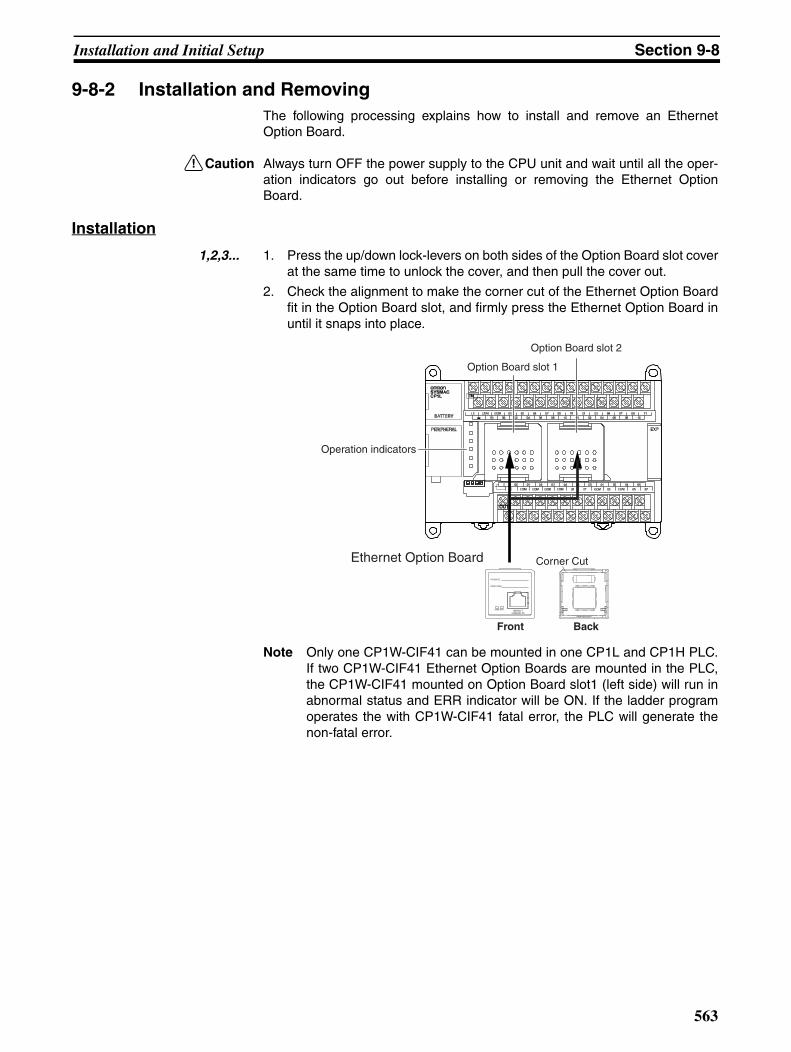
9-8-2 Installation and RemovingThe following processing explains how to install and remove an EthernetOption Board.
!Caution Always turn OFF the power supply to the CPU unit and wait until all the oper-ation indicators go out before installing or removing the Ethernet OptionBoard.
Installation
1,2,3... 1. Press the up/down lock-levers on both sides of the Option Board slot coverat the same time to unlock the cover, and then pull the cover out.
2. Check the alignment to make the corner cut of the Ethernet Option Boardfit in the Option Board slot, and firmly press the Ethernet Option Board inuntil it snaps into place.
Note Only one CP1W-CIF41 can be mounted in one CP1L and CP1H PLC.If two CP1W-CIF41 Ethernet Option Boards are mounted in the PLC,the CP1W-CIF41 mounted on Option Board slot1 (left side) will run inabnormal status and ERR indicator will be ON. If the ladder programoperates the with CP1W-CIF41 fatal error, the PLC will generate thenon-fatal error.
Ethernet Option Board
BackFront
Corner Cut
Operation indicators
Option Board slot 1
Option Board slot 2
564
Installation and Initial Setup Section 9-8
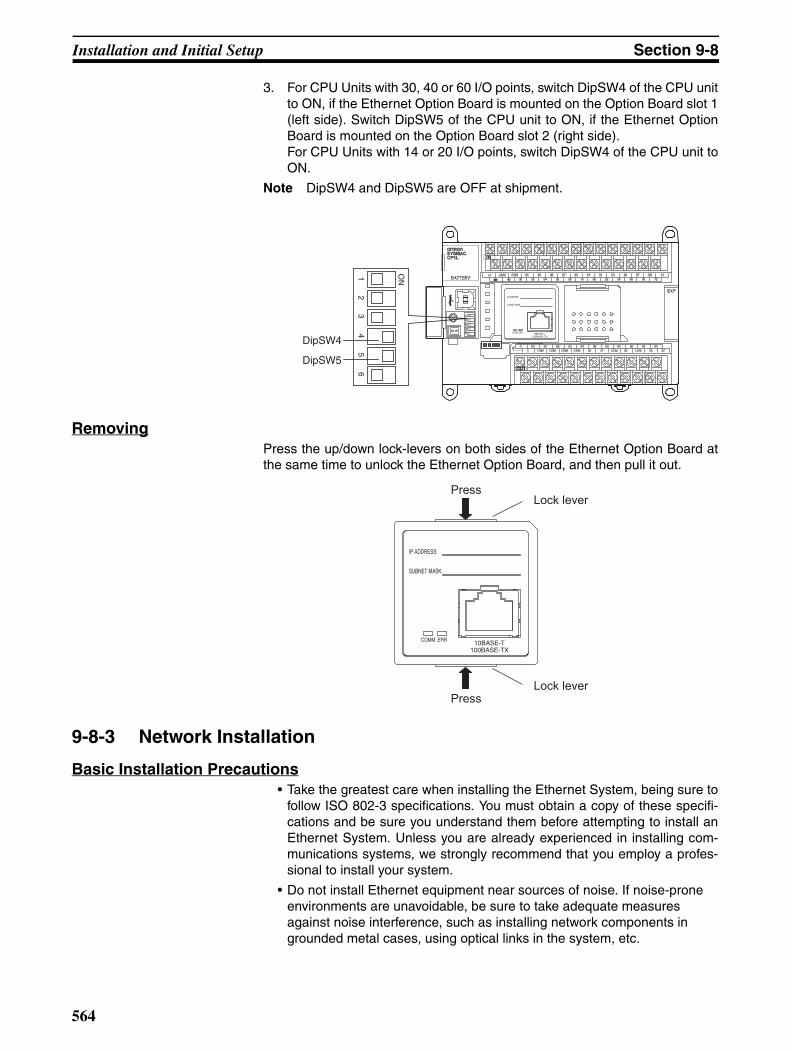
3. For CPU Units with 30, 40 or 60 I/O points, switch DipSW4 of the CPU unitto ON, if the Ethernet Option Board is mounted on the Option Board slot 1(left side). Switch DipSW5 of the CPU unit to ON, if the Ethernet OptionBoard is mounted on the Option Board slot 2 (right side).For CPU Units with 14 or 20 I/O points, switch DipSW4 of the CPU unit toON.
Note DipSW4 and DipSW5 are OFF at shipment.
RemovingPress the up/down lock-levers on both sides of the Ethernet Option Board atthe same time to unlock the Ethernet Option Board, and then pull it out.
9-8-3 Network Installation
Basic Installation Precautions• Take the greatest care when installing the Ethernet System, being sure to
follow ISO 802-3 specifications. You must obtain a copy of these specifi-cations and be sure you understand them before attempting to install anEthernet System. Unless you are already experienced in installing com-munications systems, we strongly recommend that you employ a profes-sional to install your system.
• Do not install Ethernet equipment near sources of noise. If noise-prone environments are unavoidable, be sure to take adequate measures against noise interference, such as installing network components in grounded metal cases, using optical links in the system, etc.
ON1
23
45
6
DipSW4
DipSW5
Press
PressLock lever
Lock lever
565
Installation and Initial Setup Section 9-8
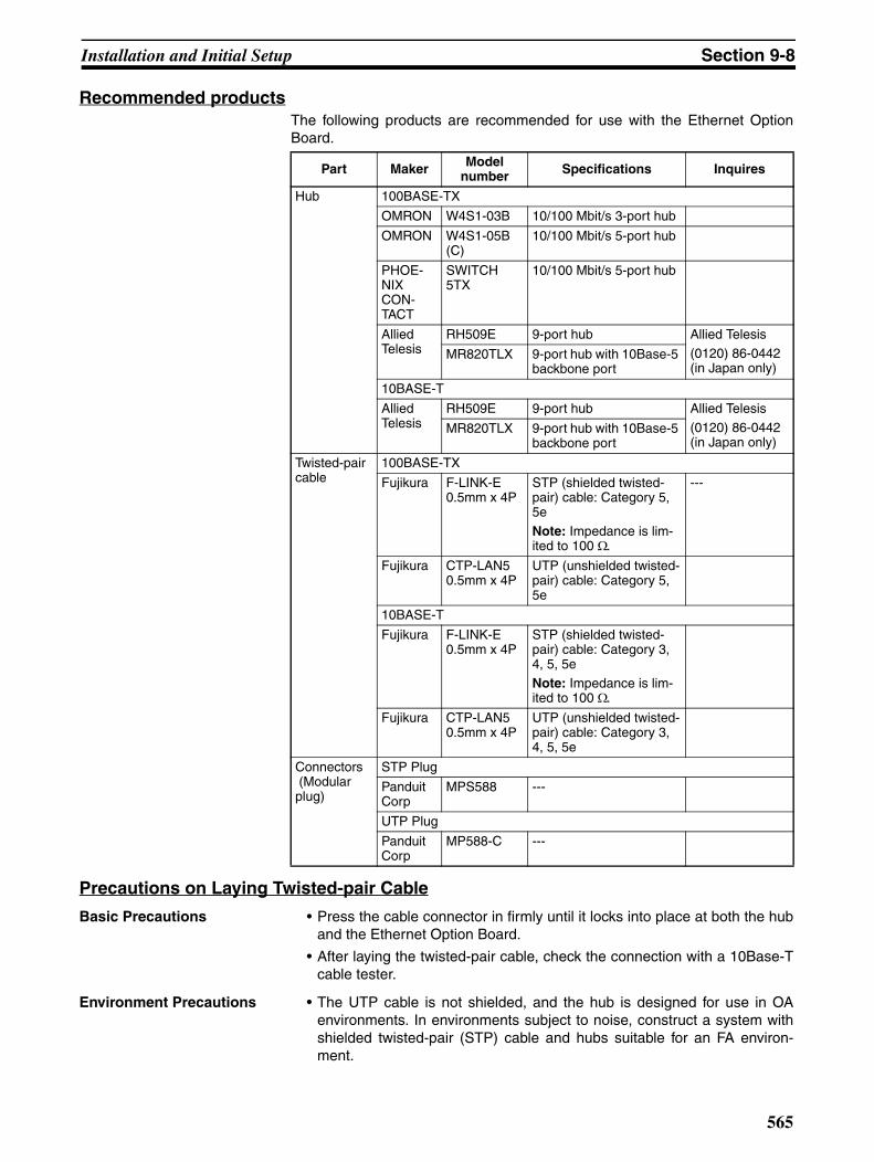
Recommended productsThe following products are recommended for use with the Ethernet OptionBoard.
Precautions on Laying Twisted-pair Cable
Basic Precautions • Press the cable connector in firmly until it locks into place at both the huband the Ethernet Option Board.
• After laying the twisted-pair cable, check the connection with a 10Base-Tcable tester.
Environment Precautions • The UTP cable is not shielded, and the hub is designed for use in OAenvironments. In environments subject to noise, construct a system withshielded twisted-pair (STP) cable and hubs suitable for an FA environ-ment.
Part Maker Model number Specifications Inquires
Hub 100BASE-TX
OMRON W4S1-03B 10/100 Mbit/s 3-port hub
OMRON W4S1-05B(C)
10/100 Mbit/s 5-port hub
PHOE-NIX CON-TACT
SWITCH 5TX
10/100 Mbit/s 5-port hub
Allied Telesis
RH509E 9-port hub Allied Telesis(0120) 86-0442(in Japan only)
MR820TLX 9-port hub with 10Base-5 backbone port
10BASE-T
Allied Telesis
RH509E 9-port hub Allied Telesis
(0120) 86-0442(in Japan only)
MR820TLX 9-port hub with 10Base-5 backbone port
Twisted-pair cable
100BASE-TX
Fujikura F-LINK-E 0.5mm x 4P
STP (shielded twisted-pair) cable: Category 5, 5e
Note: Impedance is lim-ited to 100 Ω.
---
Fujikura CTP-LAN5 0.5mm x 4P
UTP (unshielded twisted-pair) cable: Category 5, 5e
10BASE-T
Fujikura F-LINK-E 0.5mm x 4P
STP (shielded twisted-pair) cable: Category 3, 4, 5, 5e
Note: Impedance is lim-ited to 100 Ω.
Fujikura CTP-LAN5 0.5mm x 4P
UTP (unshielded twisted-pair) cable: Category 3, 4, 5, 5e
Connectors (Modular plug)
STP Plug
Panduit Corp
MPS588 ---
UTP Plug
Panduit Corp
MP588-C ---

566
Installation and Initial Setup Section 9-8
• Do not lay the twisted-pair cable together with high-voltage lines.
• Do not lay the twisted-pair cable near devices that generate noise.
• Do not lay the twisted-pair cable in locations subject to high temperatureor high humidity.
• Do not lay the twisted-pair cable in locations subject to excessive dirt anddust or to oil mist or other contaminants.
Hub Installation Environment Precautions
• Do not install the hub near devices that generate noise.
• Do not install the hub in locations subject to high temperature or highhumidity.
• Do not install the hub in locations subject to excessive dirt and dust or tooil mist or other contaminants.
Hub Connection Methods If more hub ports are required, they can be added by connecting more thanone hub. There are two possible connection methods for hubs: Cascade andstacked.
Ethernet Connectors The following standards and specifications apply to the connectors for theEthernet twisted-pair cable.
• Electrical specifications: Conforming to IEEE802.3 standards
• Connector structure: RJ45 8-pin Modular Connector
(conforming to ISO8877)
Connecting the Cable
!Caution Turn OFF the PLC’s power supply before connection or disconnecting twisted-pair cable.
!Caution Allow enough space for the bending radius of the twisted-pair cable.
1,2,3... 1. Lay the twisted-pair cable.
2. Connect the cable to the hub. Be sure to press in the cable until it locks intoplace.Request cable installation from a qualified professional.
3. Connect the cable to the connector on the Ethernet Option Board. Be sureto press in the cable until it locks into place.
Connector Pin Signal Name Abbr. Signal Direction
1 Transmission data + TD+ Output
2 Transmission data - TD- Output
3 Reception data + RD+ Input
4 Not used --- ---
5 Not used --- ---
6 Reception data - RD- Input
7 Not used --- ---
8 Not used --- ---
Hood Frame ground FG ---

567
Installation and Initial Setup Section 9-8
9-8-4 Web Browser Setting FunctionThe Ethernet Option Board’s system settings can be set using the Webbrowser of a personal computer or other device. The Ethernet Option Board’sWeb window is displayed by accessing the following URL from the Webbrowser.
English page: http://(Ethernet Option Board’s IP address)/E00.htm
Japanese page: http://(Ethernet Option Board’s IP address)/J00.htm
Chinese page: http://(Ethernet Option Board’s IP address)/C00.htm
In this example, use the following procedure to set the IP address using Inter-net Explorer version 6.0 and the Ethernet Option Board’s English Web pages.
1,2,3... 1. Connect to the Ethernet Option Board from the Web browser using theEthernet Option Board’s default IP address.http://192.168.250.1/E00.htm
2. Input the default password “ETHERNET” and click the Login Button.

568
Installation and Initial Setup Section 9-8
3. Select Settings from the menu on the left side of the window to display theSettings Menu.
4. Select 1. IP address and Protocols - System to display System menu.
5. Make the required settings (i.e., the IP address in this example).

569
Memory Allocations Section 9-9
6. After entering the correct values, click the Transfer Button to transfer thesettings to the Ethernet Option Board.
7. To enable the new settings, turn the power to the Ethernet Option BoardOFF and ON again, or click the Restart Button.
9-9 Memory Allocations
9-9-1 CIO Area AllocationThe memory allocation about communication services status in the CIO areaof PLC is shown as the following diagram. The beginning CIO channel m iscalculated by the following equation:
m = CIO2980 + 10×(0xFD - Unit Address)
The following table describes the unit address for each option port.
Service Status
!Caution Bit 15 is used for detect power condition of PLC, so do not change it at anytime. Otherwise the CP1W-CIF41 Ethernet Option Board will generate error.
Offset D15 D0
m Service Status
m+1 Error Status
m+2 FINS/TCP Connection Status
Option Port No. I/O Capacity Unit Address Range of Status Area
Option port 1 14/20 0xFC CIO2990 to CIO2992
30/40/60 0xFD CIO2980 to CIO2982
Option port 2 30/40/60 0xFC CIO2990 to CIO2992
m
15 14 13 12 11 10 9 8 7 6 5 4 3 2 1 0
1 0 0 0 0 0 0 0 0 0 0 0 0 0 0
Bit Name Unit operation
0 to 13 Reserved Always 0.
14 Link Status 0: The link between hubs is terminated.
1: A link is established between hubs.
15 Reserved Always 1.

570
Memory Allocations Section 9-9
Error StatusThe status of errors that occur at the Ethernet Option Board is reflected asshown in the following diagram.
FINS/TCP Connection Status
m+1
15 14 13 12 11 10 9 8 7 6 5 4 3 2 1 0
0 0 0 0 0 0 0 0 0 0
IP address setting errorIP address table error
IP router table errorRouting table errorAddress disagreement
EEPROM error
Bit Name Correction0 to 1 Reserved Always 0.2 IP address setting
error The following cannot be used as IP address set-tings. • Host IDs that are all 0 or all 1.• Network IDs that are all 0 or all 1.• Subnetwork IDs that are all 1.• Addresses beginning with 127 (7F hex). Reset the IP address.
3 IP address table error
Correct the IP address table. If the problem cannot be resolved,replace the CPU Unit.
4 IP router table error Correct the IP router table. If the problem cannot be resolved, replace the CPU Unit.
5 Reserved Always 0.
6 Routing table error Correct the routing tables. If the problem cannot be resolved, replace the CPU Unit.
7 to 13 Reserved Always 0.
14 Address disagree-ment
Make sure that the node number and the last byte of the IP address are the same and then set other host IDs to 0. Change the address conversion method.
15 EEPROM error Restart the PC. If the problem cannot be resolved, replace the Ethernet Option Board.
Bit Switch Unit operation
0 FINS/TCP Connection No.1 0: The connection is terminated.
1: A connection is established.
1 FINS/TCP Connection No.2 0: The connection is terminated.1: A connection is established.
2 to 15 Reserved Always 0.
m+2
15 14 13 12 11 10 9 8 7 6 5 4
0 0 0 0 0 0 0 0 0 0 0 0
3 2
0 0
1 0

571
Memory Allocations Section 9-9
9-9-2 DM Area AllocationThe memory allocation about system setup is shown as the following diagram.These data will be allocated to the DM area of PLC. The beginning DM chan-nel n is calculated by the following equation.
Note 1. DM area from n to n+154 can only display all of the settings stared in theunit. Modification in this area is invalid to the CP1W-CIF41 Ethernet OptionBoard.
2. DM area n+155 and n+156 will display the IP address used by the CP1W-CIF41 when the power is turned ON.
3. When the IP address is illegal, such as using CLASS D, CLASS E IPaddress, the values in words n+3 and n+155 will be different, and theCP1W-CIF41 will temporarily use the default IP address (192.168.250.1).Use this IP address to modify the IP address settings through Webbrowser.
n = DM32000 + 300×(0xFD - Unit Address)
The following table describes the unit address for each option port.
Offset D15 D0
n Mode setting (2 bytes)
n+1 FINS/TCP port number (2 bytes)
n+2 FINS/UDP port number (2 bytes)
n+3 IP address (4 bytes)
n+5 Subnet mask (4 bytes)
n+7 Reserved (2 bytes)
n+8 IP address table (194 bytes)
n+105 IP router table (66 bytes)
n+138 FINS/TCP connection setup (22 bytes)
n+149 HTTP server setup (10 bytes)
n+154 FINS node address (2 bytes)
n+155 Using IP Address Display/Setting Area (4 bytes)
Option Port No. I/O Capacity Unit Address Range of Status Area
Option port 1 14/20 0xFC DM32300 to DM32456
30/40/60 0xFD DM32000 to DM32156
Option port 2 30/40/60 0xFC DM32300 to DM32456
572
Memory Allocations Section 9-9
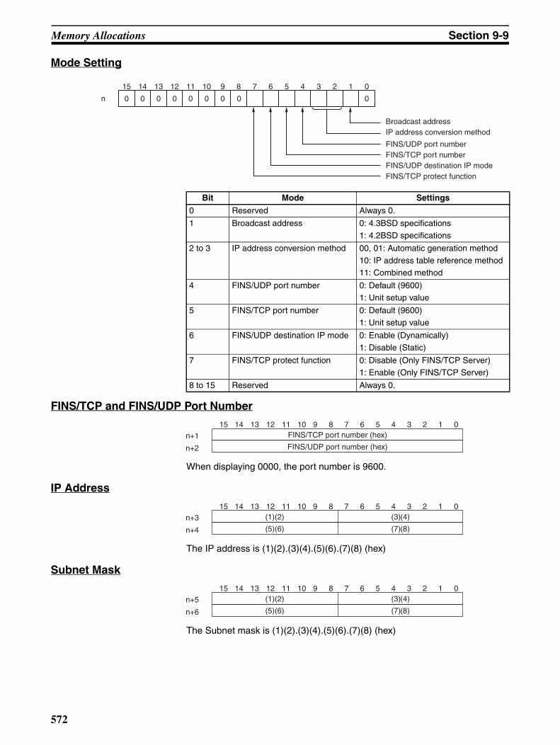
Mode Setting
FINS/TCP and FINS/UDP Port Number
When displaying 0000, the port number is 9600.
IP Address
The IP address is (1)(2).(3)(4).(5)(6).(7)(8) (hex)
Subnet Mask
The Subnet mask is (1)(2).(3)(4).(5)(6).(7)(8) (hex)
Bit Mode Settings
0 Reserved Always 0.
1 Broadcast address 0: 4.3BSD specifications
1: 4.2BSD specifications
2 to 3 IP address conversion method 00, 01: Automatic generation method10: IP address table reference method11: Combined method
4 FINS/UDP port number 0: Default (9600)1: Unit setup value
5 FINS/TCP port number 0: Default (9600)1: Unit setup value
6 FINS/UDP destination IP mode 0: Enable (Dynamically)
1: Disable (Static)
7 FINS/TCP protect function 0: Disable (Only FINS/TCP Server)1: Enable (Only FINS/TCP Server)
8 to 15 Reserved Always 0.
n
15 14 13 12 11 10 9 8 7 6 5 4 3 2 1 0
0 0 0 0 0 0 0 0 0
Broadcast addressIP address conversion method
FINS/UDP port number
FINS/UDP destination IP mode FINS/TCP protect function
FINS/TCP port number
15 14 13 12 11 10 9 8 7 6 5 4 3 2 1 0
n+1
n+2
FINS/TCP port number (hex)
FINS/UDP port number (hex)
15 14 13 12 11 10 9 8 7 6 5 4 3 2 1 0
n+3
n+4
(1)(2) (3)(4)
(5)(6) (7)(8)
15 14 13 12 11 10 9 8 7 6 5 4 3 2 1 0
n+5
n+6
(1)(2) (3)(4)
(5)(6) (7)(8)

573
Memory Allocations Section 9-9
IP Address Table
Pointer of IP Address Table
Point to the last recorder in IP address table. For example, if the last recordernumber in IP address table is 6, the value of this channel is 6.
IP Address Table Records
Each IP address table record has 6 bytes. The max number of records is 32.The configuration of the 6 bytes of data in each record is as shown in the fol-lowing diagram.
IP Router Table
Pointer of IP Router Table
Point to the last recorder in IP router table. For example, if the last recordernumber in IP router table is 6, the value of this channel is 6.
IP Router Table Records
Each IP router table record has 8 bytes. The max number of records is 8. Theconfiguration of the 8 bytes of data in each record is as shown in the followingdiagram.
FINS/TCP Connection Setup
Pointer of IP address table
IP Address table records
IP address table records
n+9 to n+11n+8 n+102 to n+104
FINS node number
1
00
IP address
6 bytes
Pointer of IP router table
IP router table records
IP router table records
n+106 to n+109n+105 n+134 to n+137
IP Network address(Network ID)
Router IP address
1 8 bytes
Offset 15 8 7 0
n+138 FINS/TCP Port Settings
n+139 FINS/TCP connection No.1 FINS/TCP connection No.1
n+140 FINS/TCP connection No.1 FINS/TCP connection No.1
n+141 FINS/TCP connection No.1 FINS/TCP connection No.2
n+142 FINS/TCP connection No.2 FINS/TCP connection No.2
n+143 FINS/TCP connection No.2 FINS/TCP connection No.2
n+144
Reserved (Always 0)
⋅⋅⋅
n+148

574
Memory Allocations Section 9-9
FINS/ TCP Port Settings
FINS/TCP Connection No.1 to 2
Each FINS/TCP connection number has 5 bytes. The configuration of the 5bytes of data in each number is as shown in the following diagram.
HTTP Server Setup
If the password for accessing the Ethernet Option Board’s Web page is forgot-ten, find out it in this area. It is written in ASCII format.
FINS Node Address
Using IP Address Display/Setting Area
The IP address is (1)(2).(3)(4).(5)(6).(7)(8) (hex)
If the local IP address in the system setup is set to a value other than 0.0.0.0,this area will act as an IP address display area and the local IP address in thesystem setup will be read and stored here when the power is turned ON or theEthernet Option Board restarted.
If the local IP address in the system setup is set to 0.0.0.0, this area will act asan IP address setting area. The value will be read by the Ethernet OptionBoard when the power is turned ON or the Ethernet Option Board restartedand is used as the local IP address.
If the IP address for accessing the Ethernet Option Board through Web browser is forgotten, find out it in this area.
Note When IP address in system setup area and DM area are all set to 0.0.0.0, theIP address will be 192.168.250.1 (FINS node address).
n+138 0000000 0 0 0 0 0 0 0 0 0
15 14 13 12 11 10 9 8 7 6 5 4 3 2 1 0
Protect setting
Bit Settings Unit operation
0 to 4 Reserved Always 0.
5 Protect setting 0: The IP address of FINS/TCP connection No.2 is not under the protection.
6 to 15 Reserved Always 0.
Destination IP address Auto-allocated FINS node
Offset 15 8 7 0
n+149
HTTP Password
⋅⋅⋅
n+152
n+153 HTTP Port number
n+154 FINS node address (hex)
The setting range is 0~ FE (hex).
15 14 13 12 11 10 9 8 7 6 5 4 3 2 1 0
15 14 13 12 11 10 9 8 7 6 5 4 3 2 1 0
n+155
n+156
(1)(2) (3)(4)
(5)(6) (7)(8)

575
Web Browser Setup and Display Section 9-10
9-10 Web Browser Setup and Display
9-10-1 Multi-language FunctionThe WEB server supports the multi-language function. The supported lan-guages are English, Chinese and Japanese.
Before setting, users should select the appropriate language in the followingULC.
English page: http://(Ethernet Option Board’s IP address)/E00.htm
Japanese page: http://(Ethernet Option Board’s IP address)/J00.htm
Chinese page: http://(Ethernet Option Board’s IP address)/C00.htm
9-10-2 Overview of Web Browser FunctionSystem setup for the Ethernet Option Board is as follows.
Monitor status for the Ethernet Option Board is as follows.
Setting Item Reference Page
System IP Address 576
Subnet Mask 576
FINS Node Address 576
FINS/UDP Port 576
FINS/TCP Port 576
Address Conversion Mode 576
FINS/UDP Option 576
Broadcast Option 577
FINS/TCP Protected 577
HTTP WEB Password 578
Port No. 578
IP Address Table FINS Node Address 579
IP Address 579
IP Router Table IP Network Address 580
Router IP Address 580
FINS/TCP IP Address 581
Auto-allocated FINS Node 581
Status Reference Page
Unit information 582
Unit status 583
FINS status 584
Error log 585
576
Web Browser Setup and Display Section 9-10
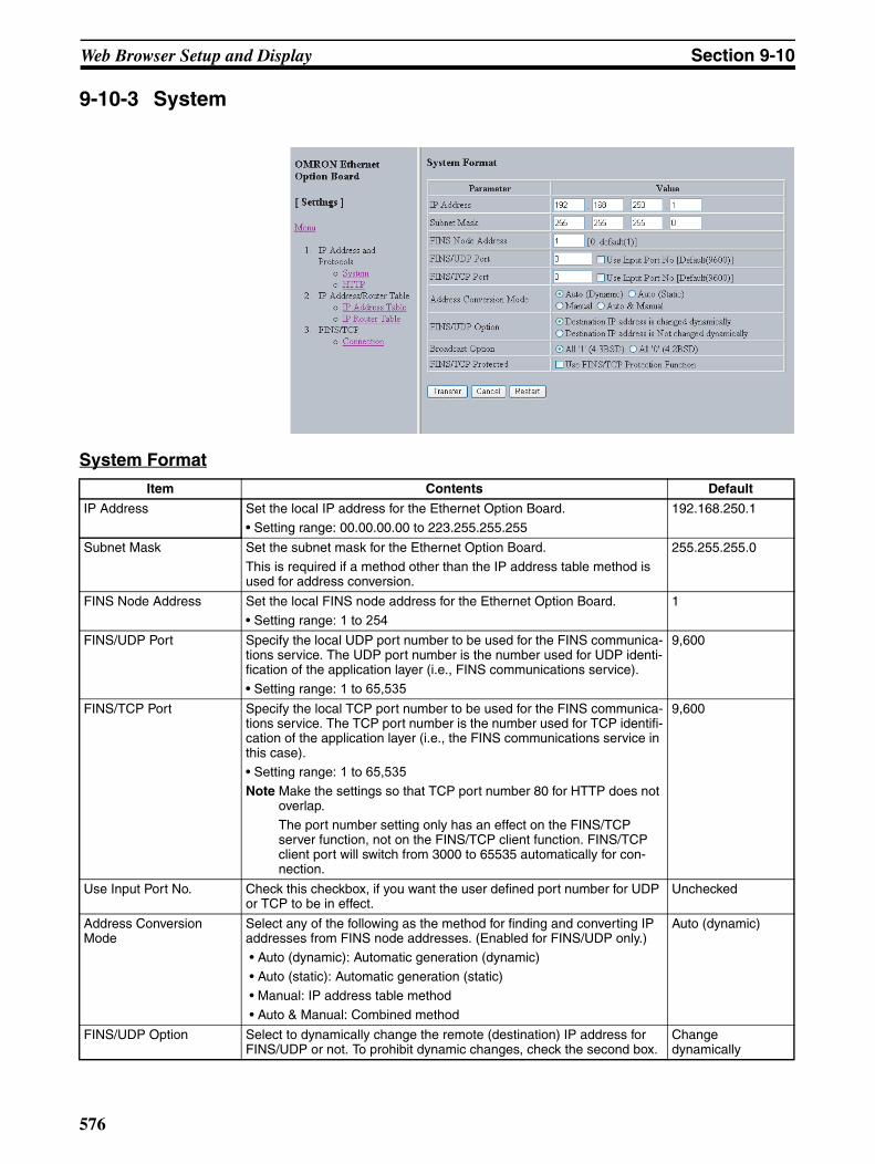
9-10-3 System
System Format
Item Contents Default
IP Address Set the local IP address for the Ethernet Option Board.• Setting range: 00.00.00.00 to 223.255.255.255
192.168.250.1
Subnet Mask Set the subnet mask for the Ethernet Option Board.
This is required if a method other than the IP address table method is used for address conversion.
255.255.255.0
FINS Node Address Set the local FINS node address for the Ethernet Option Board.
• Setting range: 1 to 254
1
FINS/UDP Port Specify the local UDP port number to be used for the FINS communica-tions service. The UDP port number is the number used for UDP identi-fication of the application layer (i.e., FINS communications service).
• Setting range: 1 to 65,535
9,600
FINS/TCP Port Specify the local TCP port number to be used for the FINS communica-tions service. The TCP port number is the number used for TCP identifi-cation of the application layer (i.e., the FINS communications service in this case).• Setting range: 1 to 65,535
Note Make the settings so that TCP port number 80 for HTTP does not overlap.The port number setting only has an effect on the FINS/TCP server function, not on the FINS/TCP client function. FINS/TCP client port will switch from 3000 to 65535 automatically for con-nection.
9,600
Use Input Port No. Check this checkbox, if you want the user defined port number for UDP or TCP to be in effect.
Unchecked
Address Conversion Mode
Select any of the following as the method for finding and converting IP addresses from FINS node addresses. (Enabled for FINS/UDP only.) • Auto (dynamic): Automatic generation (dynamic)
• Auto (static): Automatic generation (static) • Manual: IP address table method • Auto & Manual: Combined method
Auto (dynamic)
FINS/UDP Option Select to dynamically change the remote (destination) IP address for FINS/UDP or not. To prohibit dynamic changes, check the second box.
Change dynamically
577
Web Browser Setup and Display Section 9-10
The functions of the buttons are as follows.
Item Contents Default
Broadcast Option Set the method for specifying IP addresses for broadcasting in FINS/UDP.• All ‘1’ (4.3BSD): Broadcast with host number set to all ones.
• All ‘0’ (4.2BSD): Broadcast with host number set to all zeros.
Normally the default setting should be used.
All ‘1’ (4.3BSD)
FINS/TCP Protected When this option is selected, if the FINS/TCP connection is set to a server, and if an IP address other than 0.0.0.0 is set to destination IP address, any connection request from other than the setting IP address will be denied.Select this option to prevent faulty operation (by FINS commands) from specific nodes from affecting the PLC.
Unchecked
Button Function
Transfer Transfer the entered values from the personal computer to the Ethernet Option Board. (The new settings are invalid until the Ethernet Option Board has been reset.)
Cancel Cancel the entered values.
Restart Restart the Ethernet Option Board to enable the new settings after transfer.
The Restart button is invalid to the PLC.

578
Web Browser Setup and Display Section 9-10
9-10-4 HTTP
HTTP Server Setup
The functions of the buttons are as follows.
Item Contents Default
WEB Password Set the password for accessing the Ethernet Option Board’s settings and status monitor-ing information.
ETHERNET
Port Number Set the port No. used to connect to the Web browser.
80
Button Function
Transfer Transfer the entered values from the personal computer to the Ethernet Option Board. (The new settings are invalid until the Ethernet Option Board has been reset.)
Cancel Cancel the entered values.
Restart Restart the Ethernet Option Board to enable the new settings after transfer.
The Restart button is invalid to the PLC.

579
Web Browser Setup and Display Section 9-10
9-10-5 IP Address TableSet the IP address table that defines the relationship between FINS nodeaddresses and IP addresses. With FINS/UDP, this is enabled only when theIP address table method is set to the IP address conversion method.
The functions of the buttons are as follows.
Item Contents Default
FINS Node Address Set the node address for the remote device. None
IP Address Set the related IP address for the remote device. None
Button Function
Transfer Transfer the entered values from the personal computer to the Ethernet Option Board. (The new settings are invalid until the Ethernet Option Board has been reset.)
Cancel Cancel the entered values.
Restart Restart the Ethernet Option Board to enable the new settings after transfer.The Restart button is invalid to the PLC.
Show Show the FINS node address and IP address of the selected No.
Delete Delete the IP address table of the selected No.

580
Web Browser Setup and Display Section 9-10
9-10-6 IP Router TableSet the IP router table when the Ethernet Option Board is to communicatethrough the IP router with nodes on another IP network segment.
The functions of the buttons are as follows.
Item Contents Default
IP Network Address
Set the network ID from the IP address. None
Router IP Address
Set the related IP address of a router connected to a network.
None
Button Function
Transfer Transfer the entered values from the personal computer to the Ethernet Option Board. (The new settings are invalid until the Ethernet Option Board has been reset.)
Cancel Cancel the entered values.
Restart Restart the Ethernet Option Board to enable the new settings after transfer.The Restart button is invalid to the PLC.
Show Show the IP network address and Router IP address of the selected No.
Delete Delete the IP router table of the selected No.

581
Web Browser Setup and Display Section 9-10
9-10-7 FINS/TCP
FINS/TCP Connection Setup
The functions of the buttons are as follows.
Item Contents Default
No. Shows the connection number. This is a network API used when TCP is used for the FINS communica-tions service. Up to 2 can be used at a time, and they are identified by connection numbers 1 to 2. The Ethernet Option Board can thus simultaneously execute the FINS communications service by TCP with up to 2 remote nodes.
---
IP Address • When the Ethernet Option Board is used as a server:
If the option is selected to use IP addresses to pro-tect, set the IP addresses as required at clients from which connection is permitted. If not set for those connections, the default setting can be used.
• When the Ethernet Option Board is used as a client:
Set the IP address for the remote Ethernet Unit (i.e., the server) that is to be connected by FINS/TCP. It is required that an IP address be set for the remote Ethernet Unit.
0.0.0.0
Auto-allocated FINS node
If the client (normally a personal computer) applica-tion supports FINS/TCP, and if FINS node addresses are not fixed, the client will take 0 as its node address. Then, when a FINS command arrives, the number set here (from 251 to 252) will automatically be allocated as the client’s FINS node address.
From 251 to 252, for connection No. 1 to 2
Button Function
Transfer Transfer the entered values from the personal computer to the Ethernet Option Board. (The new settings are invalid until the Ethernet Option Board has been reset.)
Cancel Cancel the entered values.
Restart Restart the Ethernet Option Board to enable the new settings after transfer.
The Restart button is invalid to the PLC.

582
Web Browser Setup and Display Section 9-10
9-10-8 Unit Information
Parameter Contents
Model Show the model information of the Ethernet Option Board.
Version Show the version information of the Ethernet Option Board.
IP Address Show the IP address of the Ethernet Option Board.
Subnet Mask Show the subnet mask of the Ethernet Option Board.
FINS/UDP Port Number Show the FINS/UDP port number of the Ethernet Option Board.
Use Input Port Number Show the effective port number setting mode.
Broadcast Setting Show the broadcast setting of the Ethernet Option Board.
IP Address Conversion Show the IP address conversion method of the Ether-net Option Board.
Ethernet Address Show the MAC ID of the Ethernet Option Board.

583
Web Browser Setup and Display Section 9-10
9-10-9 Unit Status
Parameter Contents
Error Flags Indicate the operating status and errors that occurred when the Ethernet Option Board is turned ON.
Total Number of Packets Received
Show the total number of packets received by the Ether-net Option Board.
Total Number of Receive Errors
Show the total number of errors detected while the Ether-net Option Board was receiving.The types of errors detected are short packet errors, alignment errors, CRC errors, frame length errors and communication controller overflow errors.
Total Number of Packets Sent
Show the total number of packets sent by the Ethernet Option Board.
Total Number of Errors Sent
Show the total number of errors detected while the Ether-net Option Board was sending.

584
Web Browser Setup and Display Section 9-10
9-10-10 FINS Status
The details of TCP status are listed as the following table.
The function of the button is as follows.
Parameter ContentsNode Show the FINS node address.Connection Type Show the protocol used by connection with the related
node address.Local Port No. Show the port number of the Ethernet Option Board for
connection with the related node address.Remote IP Show the IP address of the related node address.Remote Port No. Show the remote port number of the related node address
for connection.TCP Connection No. If the connection is the FINS/TCP, show the connection
number (1 to 4).TCP Status If the connection is the FINS/TCP, show the current con-
nection status.
Status MeaningCLOSED Connection closedLISTEN Waiting for connectionSYN SENT SYN sent in active statusSYN RECEIVED SYN received and sentESTABLISHED Already establishedCLOSE WAIT FIN received and waiting for completionFIN WAIT1 Completed and FIN sentCLOSING Completed and exchanged FIN. Awaiting ACK.LAST ACK FIN sent and completed. Awaiting ACK.FIN WAIT2 Completed and ACK received. Awaiting FIN.TIME WAIT After closing, pauses twice the maximum segment life (2MSL).
Button FunctionSend Show the FINS status of the selected No.

585
Web Browser Setup and Display Section 9-10
9-10-11 Error Log
The functions of the buttons are as follows.
Parameter Contents
No. Show the error recorder number.
Error Code Show the error code of the error recorder.
Detail Code Show the detail error code of the error recorder.
Date Show the date of the error recorder.
Button Function
Send Show the error log of the selected No.
Clear Error Log Clear the error log table.

586
Trouble Shooting Section 9-11
9-11 Trouble Shooting
9-11-1 Error LogThe Ethernet Option Board provides an error log that records errors occurredduring Ethernet Option Board operation. The contents of the error log can beread or cleared from the Web Brower.
Logged Errors The following errors are recorded in the error log.
• Errors in network operation
• Errors in data transfers
• Error in the CPU unit
Error Log Table Each error is recorded as one record in an error log table. Up to 64 recordscan be saved. If more than 20 errors occur, the oldest errors will be deletedfrom the error log and the most recent error will be recorded.
The following information is recorded in the error log table.
• Main error code (see table later in this section)
• Detailed error code (see table later in this section)
• Time stamp (from the clock in the CPU unit)
Note During the initialization of the Ethernet Option Board, if an error occurs, theerror log time stamp will record as 2000-00-00 00:00:00.
Error Log Location When an error is detected, the error codes and time stamp are recorded in theerror log in RAM inside the Ethernet Option Board. Serious errors are alsorecorded in EEPROM. The maximum number of errors that can be saved toEEPROM is 20 for the CP1L and CP1H. The errors recorded in EEPROM willbe saved even if the unit is restarted or power is turned OFF.
Error Codes
Errorcode
ERRLED
MeaningDetailed error code
Correction EEPROM1st byte 2nd byte
0002 LIT CPU Unit service monitoring error
Monitor time (ms) Check and correct the CPU Unit’s operating envi-ronment.NoteRecovery is possible for this error. When operation is restored, operations will return to normal.
Saved
0012 FLASH CPU unit memory error 01: Read error02: Write error
03: outing table05: CPU Bus Unit Words
(CIO/DM)
01: Recreate the data specified by the 2nd byte of the detailed error code.02: Clear memory using procedure in the PLC operation manual.
Saved
0013 FLASH CPU unit protected 00 00 Remove protection from CPU Unit memory.
Saved
0014 FLASH CPU Unit Power Failure Restart the PLC (Power OFF and Power ON)
---
0015 FLASH CPU Unit fatal error Eliminate the cause of the error in the CPU Unit.
---

587
Trouble Shooting Section 9-11
010E --- No routing table entry (send failed)
Commands
Bit 15: OFFBits 08 to 14: SNABits 00 to 07: SA1
ResponsesBit 15: ON
Bits 08 to 14: DNABits 00 to 07: DA1
Set the local node, remote node, and relay nodes in the routing tables.
---
010F --- Routing table error (send failed)
Create the routing tables correctly.
---
0110 --- Too many relay points (send failed)
Reconstruct the network or correct the routing tables so that commands are sent to within a 3- level network range.
---
0111 --- Command too long (send failed)
Check the command for-mat and set the correct command data.
---
0112 --- Header error (send failed) Check the command for-mat and set the correct command data.
---
0117 --- Internal buffers full; packet discarded
Change the network so that traffic is not concen-trated.
---
0120 --- Unexpected routing error Check the routing tables. ---
0123 --- Internal send buffers full; packet discarded
Change the network so that traffic is not concen-trated.
---
0125 --- Time out error Resend the command. ---
021A FLASH Logic error in setting table 00 02: Networkparameters03: Routing
tables04: UnitSetup
05: CPU BusUnit Words(CIO/DM)
Recreate the data speci-fied by the 2nd byte of the detailed error code.
Saved
03C0 FLASH FINS/TCP setting error 01 to 02:
Connection No.
01: Automatically allocated
FINS node addressduplication
02: DestinationIP address error03: Destination
port number error
Set the FINS/TCP settings correctly.
---
03C2 --- FINS/TCP packet discarded
01 to 02: Connection No.
03:Receptionerror04:Transmission error
Resend the command. ---
There is too much load (traffic) on the Ethernet Option Board. Correct the system so that traffic is not concentrated.
---
Errorcode
ERRLED
MeaningDetailed error code
Correction EEPROM1st byte 2nd byte

588
Trouble Shooting Section 9-11
03C3 --- FINS/UDP Packet discarded
00 01 to FENode address
The automatic generation (static) method was used as the IP address conver-sion method, so remote IP address information in internal memory could not be changed.
---
03C8 --- Socket Error Arbitrary Resend the packet or the destination node is not in the network.
---
03D0 FLASH System setup sum value error
Reset the value of system setup area, Restart CPU Unit.
Saved
0601 LIT Option Board error Arbitrary Restart the CPU Unit. If the problem persists, replace the Ethernet Option Board.
Saved
0602 LIT Option Board memory error 01: Read error
02: Write error
04:System setup06:Error log09:Identity data11: Mac ID
Restart the CPU Unit. If the problem persists, replace the Ethernet Option Board.
Saved (except error log)
Errorcode
ERRLED
MeaningDetailed error code
Correction EEPROM1st byte 2nd byte

589
Trouble Shooting Section 9-11
9-11-2 Trouble-shooting with Indicators and Error Code DisplayERR
Indicator Error Probably Cause Error code (hex) Correction
Lit CPU Unit service monitoring error
Service from the CPU Unit was not com-pleted within the fixed interval. The monitor-ing time is normally 11s.
0002 Check and correct the CPU Unit’s operating environment.Check whether the related DIP SW is on.Refer to 9-8-2 Installation and Removing.
Note Recovery is possible for this error. When operation is restored, it will return to normal.
Two option boards installed
Two option boards have been installed on the CPU Unit.
--- Uninstall the Ethernet Option Board in one serial port of the CPU Unit and restart the CPU unit.
Option board error An error occurred in the Ethernet Option Board.
0601 Restart the CPU Unit. Replace the Ethernet Option Board if the error recurs.
Option board memory error
An error occurred in the Unit’s non-volatile memory itself. This error will occur while writing or reading the error log, system setup, identity data, MAC ID.
0602 Restart the CPU Unit. Replace the Ethernet Option Board if the error recurs.
Flashing CPU Unit memory error
A parity error occurred during an operation such as reading the routing tables.
0012 Register the routing table in the CPU Unit again and restart the CPU Unit. Replace the CPU Unit if the error recurs.
CPU Unit pro-tected
CPU Unit protected. 0013 Remove protection from CPU Unit memory.
CPU Unit fatal error
A fatal error occurred in the CPU Unit.
0015 Eliminate the cause of the error in the CPU Unit.
CPU Unit power failure
CPU Unit power OFF, Ethernet Option Board is still running.
0014 Restart the PLC (Power OFF and power ON).
IP address setting error
The IP address is set incorrectly.
021A Correct the IP address. Do not set any ofthe following IP addresses.• Host IDs that are all 0 or all 1.
• Network IDs that are all 0 or all 1.
• Subnetwork IDs that are all 1.
• Addresses beginning with 127 (7F hex).
IP address table error
The IP address table is set incorrectly.
021A Correct the IP address table.
IP Router table setting error
The IP Router table is set incorrectly.
021A Correct the IP Router table.

590
Trouble Shooting Section 9-11
9-11-3 Error StatusThe status of errors that occur at the Ethernet Option Board is reflected in CIOrelation area, Refer to 9-9-1 CIO Area Allocation, Error Status for details.
ERR Indicator
Error Probably Cause Error code (hex)
Correction
Flashing Address Disagreement
The node number set for the option board does not agree with the host ID in the IP address. This proba-bly occurs when the address conversion method is set for auto-matic address genera-tion.
021A Make sure that the node number and the last byte of the IP address are the same and then set other host IDs to 0.Change the address conversion method.
Logic error in setting table
There is a logic error in the setting table.
021A Recreate the data specified by the 2nd byte of the detailed error code.
System setup Sum check error
The Checksum of System setup is incor-rect.
03D0 Reset the value of system setup area. Restart the CPU Unit.
FINS/TCP setting error
The settings of FINS/TCP are incorrect.
03C0 Refer to operation manual and set the FINS/TCP setting correctly.

591
Sample Application Section 9-12
9-12 Sample ApplicationThe following examples show how to connect online from a CX-Programmeron an Ethernet network to a PLC on the Ethernet network.
Note Please use CX-Programmer version 8.1 or higher (CX-ONE version 3.1 orhigher).
■ System Configuration Example 1: No Routing
In this example, an online connection is made by FINS/UDP to a PLC on anEthernet network (PLC1 in the diagram below) from a CX-Programmer / CX-Integrator connected to the Ethernet network.
Web Browser Setting
CX-Programmer/CX-Integrator
Ethernet (Network address: None)
Ethernet port
Target: PLC1
Ethernet Option BoardIP address: 192.168.250.1
FINS/UDP method
Node number: 1
IP address conversion: Automatic generation method (dynamic)
Ethernet Option Board node number: 2Ethernet Option Board IP address: 192.168.250.2
COMMERR 10BASE-T100BASE-TX
Item SettingBroadcast All ones (4.3BSD)FINS/UDP port Default (9600)IP address 192.168.250.2Subnet mask 255.255.255.0FINS Node Address 2IP address conversion Automatic generation method (dynamic)Baud rate Automatic DetactionIP router tabel None

592
Sample Application Section 9-12
CX-Programmer’s Change PLC Dialog Box
Note Limited by the CP1W-CIF41 inner bus protocol (Toolbus), the frame lengthand response monitor time are different from the existing Ethernet unit.
Inputs to the CX-Programmer’s Setup Window
Change PLC Settings
Item Setting
PLC name PLC1
Network classification Ethernet
Network Tab FINS transmission source address 0
FINS destination Network number 0
Node address 2
Frame length 1,004bytes
Response monitor time 5 seconds
Driver Tab Workstation node address 1
Automatic generation method Not selected
Ethernet Option Board IP address 192.168.250.2
Port number 9600

593
Sample Application Section 9-12
Network Settings (Network Tab)
Network Settings (Driver Tab)

594
Sample Application Section 9-12
■ System Configuration Example 2: Using Routing Tables
In this example, an online connection is made via the Ethernet to a PLC on aController Link network (PLC3 in the diagram below) from a CX-Programmer /CX-Integrator connected to the Ethernet network.
Web Browser Setting
Same as for System Configuration Example 1.
CX-Programmer’s Change PLC Dialog Box
COMMERR 10BASE-T100BASE-TX
(PC1)
(PC2)
(CP1H)
PLC1
PLC3PLC2
(CJ2H)
(CJ1H)
Ethernet #001
FINS AddressNet: #2, Node #3
FINS AddressNet: #1, Node #1
FINS AddressNet: #1, Node #3
Ethernet #002
192.168.2.100
192.168.1.2
192.168.1.1 192.168.1.3
Toolbus
192.168.2.3
Settings for target PLC (PLC1)’s Change PLC Dialog Box Setting
PLC name PLC2
Network classification PLC1
Network Tab FINS transmission source address 2
FINS destination Network number 1
Node address 1
Frame length 542bytes (default)
Response monitor time 5 seconds

595
Sample Application Section 9-12
Routing Table Settings and Transfer to Each PLC
Set the routing tables with CX-Integrator, and transfer them.
1,2,3... 1. Using CX-Integrator, connect online, and select Routing table - Settings.Then create FINS local routing tables (a local network table and a relaynetwork table).
Example: PLC 1 Routing Table Settings• Local Network Table
• Relay Network Table (None)Example: PLC 2 and PLC 3 Routing Table Settings• Local Network Table
• Relay Network TableIn order to relay from PLC2/3 to the final network number 2, it is neces-sary to relay via node address 1 on relay network number 2.
2. Save the routing table file (File - Save local routing table file).
3. Select New from the Project Menu, and save with a file name. Then selectAdd Device from the Project Menu. For each PLC, register a PLC with adirect serial connection (node address: 0), and select it.
4. With CX-Integrator, select Open from the PLC Menu.
5. Select Routing table - Setup, read the saved file, and select Options -Transfer to PLC. Click Yes to transfer the routing tables to the connectedPLCs.
Unit number Local network number
0 1
1 2
Option port No. I/O capacity Unit address Local network number
Option port 1 14/20 252(0xFC hex) 1
30/40/60 253(0xFD hex) 1
Option port 2 30/40/60 252(0xFC hex) 1
Final network number Relay network number Relay node address
2 1 2

596
Sample Application Section 9-12