Omron CP1W-MODTCP61 CP1L / CP1H / CJ2M · PDF fileThe CP1W- MODTCP61 is an adapter that allows...
18
Omron CP1W-MODTCP61 CP1L / CP1H / CJ2M Modbus/TCP Adapter Application and Setup Guide Revision 2.00a 7/29/2011 www.infoPLC.net
Transcript of Omron CP1W-MODTCP61 CP1L / CP1H / CJ2M · PDF fileThe CP1W- MODTCP61 is an adapter that allows...
Omron CP1W-MODTCP61
CP1L / CP1H / CJ2M Modbus/TCP Adapter
Application and Setup Guide
Revision 2.00a 7/29/2011
www.infoPLC.net
2
Section 1: Introduction
This document explains the theory, operation, and setup of the Omron CP1W-MODTCP61 Modbus/TCP adapter.
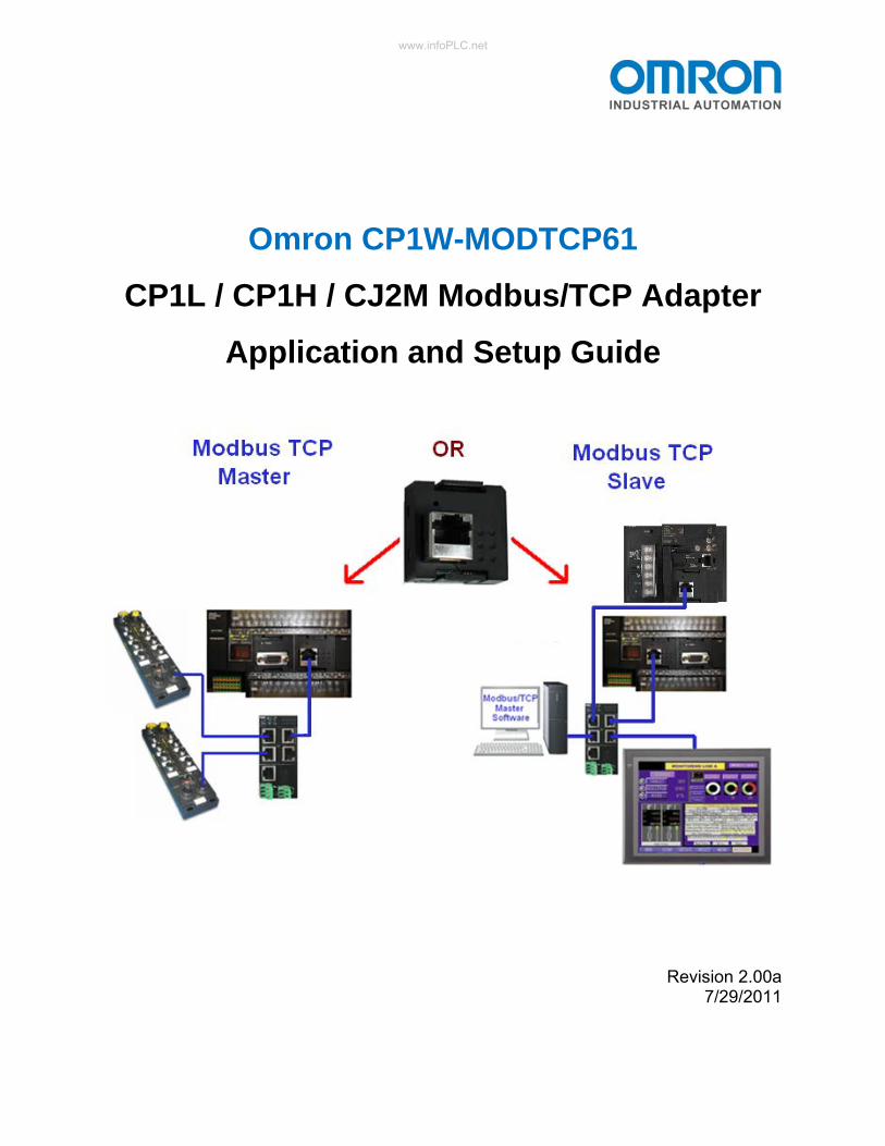
The CP1W- MODTCP61 is an adapter that allows a CP1L or CP1H PLC to operate in 1 of 2 modes, but not both at the same time. For clarity, the discussion of the setup and operation of each of these 2 modes is handled in separate sections of this document.
The adapter also allows a CJ2M-CPU3 series PLC to operate in Slave mode only.
The two modes of operation are:
Mode 1: Modbus TCP Slave / Server. In this mode, the adapter functions as a slave device, allowing other Modbus TCP Master devices to send commands to and receive responses from the adapter using the Modbus TCP protocol.
Mode 2: Modbus TCP Master / Client. In this mode, the adapter functions as a master device, sending Modbus TCP commands to and receiving responses from other slave devices, such as IO blocks, inverters, PLCs, etc. Note: this mode is not applicable to CJ2M-CPU3 series PLCs.
Mounting an adapter in a PLC
CP1 Series: The adapter mounts in the Option Board Slot on the front of a CP1L or CP1H PLC, and can be used in all CP1L / CP1H PLCs with an available Option Board Slot. A CP1L or CP1H PLC with 2 option board slots can use 2 CP1W-MODTCP61 adapters, with 1 functioning as a Modbus TCP Master / Client and 1 functioning as a Modbus TCP Slave / Server.
CJ2M Series: The adapter mounts in the Option Board Slot on the front of a CJ2M-CPU3 PLC. When used in a CJ2M-CPU3 series PLC, the adapter will only function as a Modbus TCP Slave / Server. The adapter is not applicable for CJ2M-CPU1 series PLCs.
www.infoPLC.net
3
Section 2 - Modbus TCP Slave / Server
2.1 Modbus TCP Slave / Server Overview
When configured for Modbus TCP Slave / Server mode, the adapter functions as a slave node, allowing other Modbus TCP Master / Client devices to send commands to and receive responses from the adapter. These master devices include PCs with software that uses the Modbus TCP protocol, as well as PLCs and other hardware devices functioning as Modbus TCP masters.
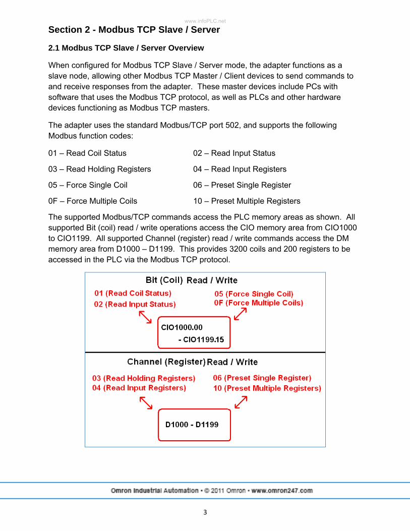
The adapter uses the standard Modbus/TCP port 502, and supports the following Modbus function codes:
01 – Read Coil Status 02 – Read Input Status
03 – Read Holding Registers 04 – Read Input Registers
05 – Force Single Coil 06 – Preset Single Register
0F – Force Multiple Coils 10 – Preset Multiple Registers
The supported Modbus/TCP commands access the PLC memory areas as shown. All supported Bit (coil) read / write operations access the CIO memory area from CIO1000 to CIO1199. All supported Channel (register) read / write commands access the DM memory area from D1000 – D1199. This provides 3200 coils and 200 registers to be accessed in the PLC via the Modbus TCP protocol.
www.infoPLC.net
4
2.2 Modbus Addressing in the PLC
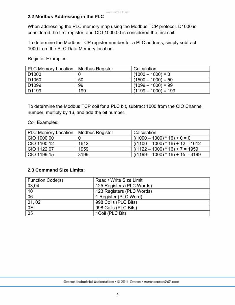
When addressing the PLC memory map using the Modbus TCP protocol, D1000 is considered the first register, and CIO 1000.00 is considered the first coil.
To determine the Modbus TCP register number for a PLC address, simply subtract 1000 from the PLC Data Memory location.
Register Examples:
PLC Memory Location Modbus Register Calculation D1000 0 (1000 – 1000) = 0 D1050 50 (1500 – 1000) = 50 D1099 99 (1099 – 1000) = 99 D1199 199 (1199 – 1000) = 199
To determine the Modbus TCP coil for a PLC bit, subtract 1000 from the CIO Channel number, multiply by 16, and add the bit number.
Coil Examples:
PLC Memory Location Modbus Register Calculation CIO 1000.00 0 ((1000 – 1000) * 16) + 0 = 0 CIO 1100.12 1612 ((1100 – 1000) * 16) + 12 = 1612 CIO 1122.07 1959 ((1122 – 1000) * 16) + 7 = 1959 CIO 1199.15 3199 ((1199 – 1000) * 16) + 15 = 3199
2.3 Command Size Limits:
Function Code(s) Read / Write Size Limit 03,04 125 Registers (PLC Words) 10 123 Registers (PLC Words) 06 1 Register (PLC Word) 01, 02 998 Coils (PLC Bits) 0F 998 Coils (PLC Bits) 05 1Coil (PLC Bit)
www.infoPLC.net
5
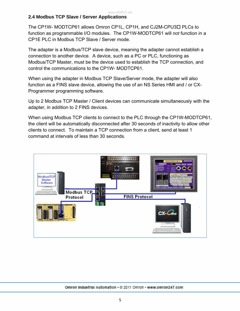
2.4 Modbus TCP Slave / Server Applications
The CP1W- MODTCP61 allows Omron CP1L, CP1H, and CJ2M-CPU3 PLCs to function as programmable I/O modules. The CP1W-MODTCP61 will not function in a CP1E PLC in Modbus TCP Slave / Server mode.
The adapter is a Modbus/TCP slave device, meaning the adapter cannot establish a connection to another device. A device, such as a PC or PLC, functioning as Modbus/TCP Master, must be the device used to establish the TCP connection, and control the communications to the CP1W- MODTCP61.
When using the adapter in Modbus TCP Slave/Server mode, the adapter will also function as a FINS slave device, allowing the use of an NS Series HMI and / or CX- Programmer programming software.
Up to 2 Modbus TCP Master / Client devices can communicate simultaneously with the adapter, in addition to 2 FINS devices.
When using Modbus TCP clients to connect to the PLC through the CP1W-MODTCP61, the client will be automatically disconnected after 30 seconds of inactivity to allow other clients to connect. To maintain a TCP connection from a client, send at least 1 command at intervals of less than 30 seconds.
www.infoPLC.net
6
2.5 Modbus TCP Slave / Server Setup
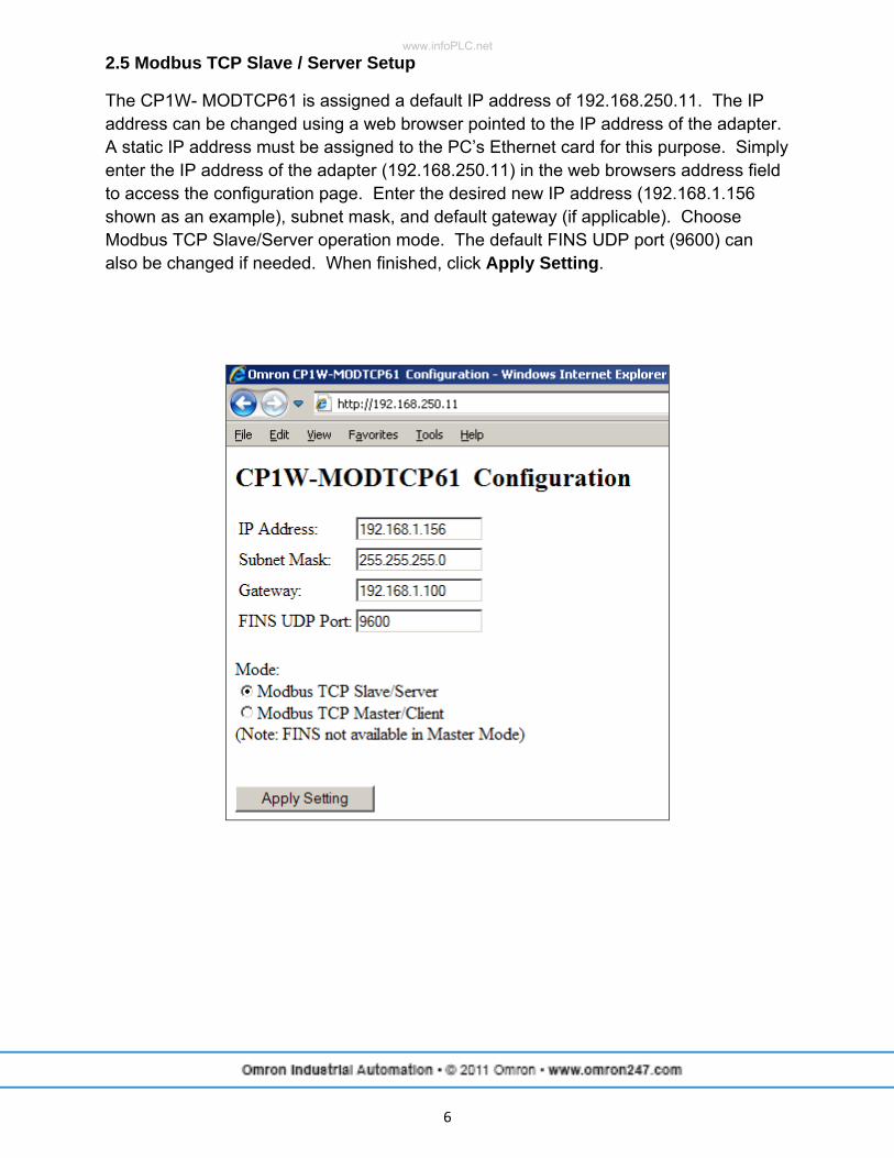
The CP1W- MODTCP61 is assigned a default IP address of 192.168.250.11. The IP address can be changed using a web browser pointed to the IP address of the adapter. A static IP address must be assigned to the PC’s Ethernet card for this purpose. Simply enter the IP address of the adapter (192.168.250.11) in the web browsers address field to access the configuration page. Enter the desired new IP address (192.168.1.156 shown as an example), subnet mask, and default gateway (if applicable). Choose Modbus TCP Slave/Server operation mode. The default FINS UDP port (9600) can also be changed if needed. When finished, click Apply Setting.
www.infoPLC.net
7
2.6 Modbus TCP Slave / Server PLC Setup
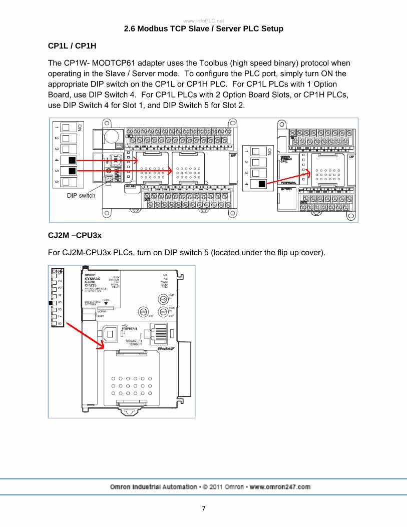
CP1L / CP1H
The CP1W- MODTCP61 adapter uses the Toolbus (high speed binary) protocol when operating in the Slave / Server mode. To configure the PLC port, simply turn ON the appropriate DIP switch on the CP1L or CP1H PLC. For CP1L PLCs with 1 Option Board, use DIP Switch 4. For CP1L PLCs with 2 Option Board Slots, or CP1H PLCs, use DIP Switch 4 for Slot 1, and DIP Switch 5 for Slot 2.
CJ2M –CPU3x
For CJ2M-CPU3x PLCs, turn on DIP switch 5 (located under the flip up cover).
www.infoPLC.net
8
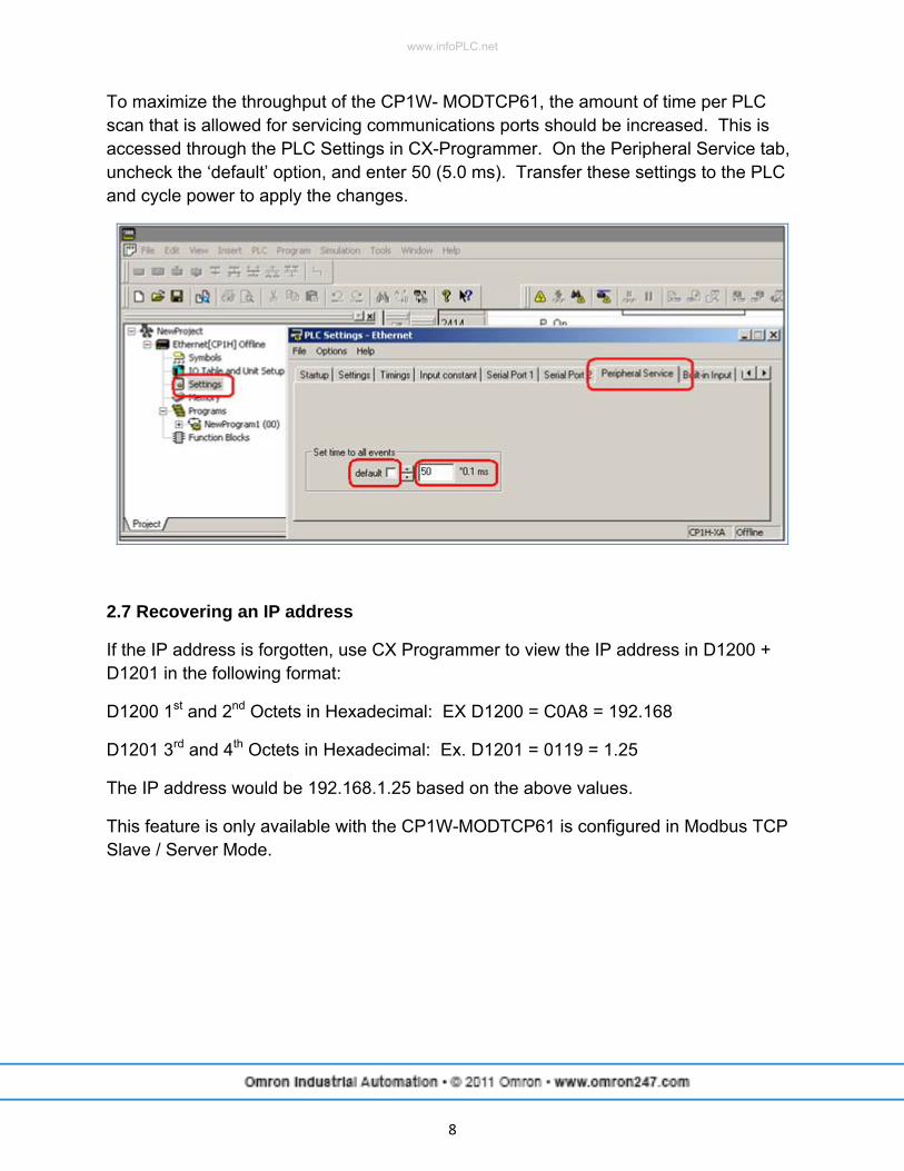
To maximize the throughput of the CP1W- MODTCP61, the amount of time per PLC scan that is allowed for servicing communications ports should be increased. This is accessed through the PLC Settings in CX-Programmer. On the Peripheral Service tab, uncheck the ‘default’ option, and enter 50 (5.0 ms). Transfer these settings to the PLC and cycle power to apply the changes.
2.7 Recovering an IP address
If the IP address is forgotten, use CX Programmer to view the IP address in D1200 + D1201 in the following format:
D1200 1st and 2nd Octets in Hexadecimal: EX D1200 = C0A8 = 192.168
D1201 3rd and 4th Octets in Hexadecimal: Ex. D1201 = 0119 = 1.25
The IP address would be 192.168.1.25 based on the above values.
This feature is only available with the CP1W-MODTCP61 is configured in Modbus TCP Slave / Server Mode.
www.infoPLC.net
9
Section 3 - Modbus TCP Master / Client
3.1 Modbus TCP Master / Client Overview
When configured for Modbus TCP Master / Client mode, the adapter functions as a master device, controlling the communications with other slave devices such as IO blocks, inverters, PLCs, etc. The adapter sends Modbus TCP commands to and receives Modbus TCP responses from the slave devices.
3.2 Modbus TCP Master / Client Applications
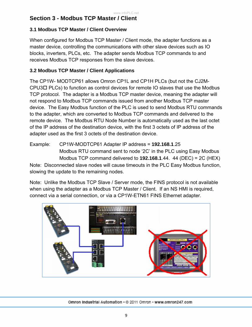
The CP1W- MODTCP61 allows Omron CP1L and CP1H PLCs (but not the CJ2M-CPU3 PLCs) to function as control devices for remote IO slaves that use the Modbus TCP protocol. The adapter is a Modbus TCP master device, meaning the adapter will not respond to Modbus TCP commands issued from another Modbus TCP master device. The Easy Modbus function of the PLC is used to send Modbus RTU commands to the adapter, which are converted to Modbus TCP commands and delivered to the remote device. The Modbus RTU Node Number is automatically used as the last octet of the IP address of the destination device, with the first 3 octets of IP address of the adapter used as the first 3 octets of the destination device.
Example: CP1W-MODTCP61 Adapter IP address = 192.168.1.25 Modbus RTU command sent to node ‘2C’ in the PLC using Easy Modbus Modbus TCP command delivered to 192.168.1.44. 44 (DEC) = 2C (HEX) Note: Disconnected slave nodes will cause timeouts in the PLC Easy Modbus function, slowing the update to the remaining nodes.
Note: Unlike the Modbus TCP Slave / Server mode, the FINS protocol is not available when using the adapter as a Modbus TCP Master / Client. If an NS HMI is required, connect via a serial connection, or via a CP1W-ETN61 FINS Ethernet adapter.
www.infoPLC.net
10
3.3 Modbus TCP Master / Client Setup
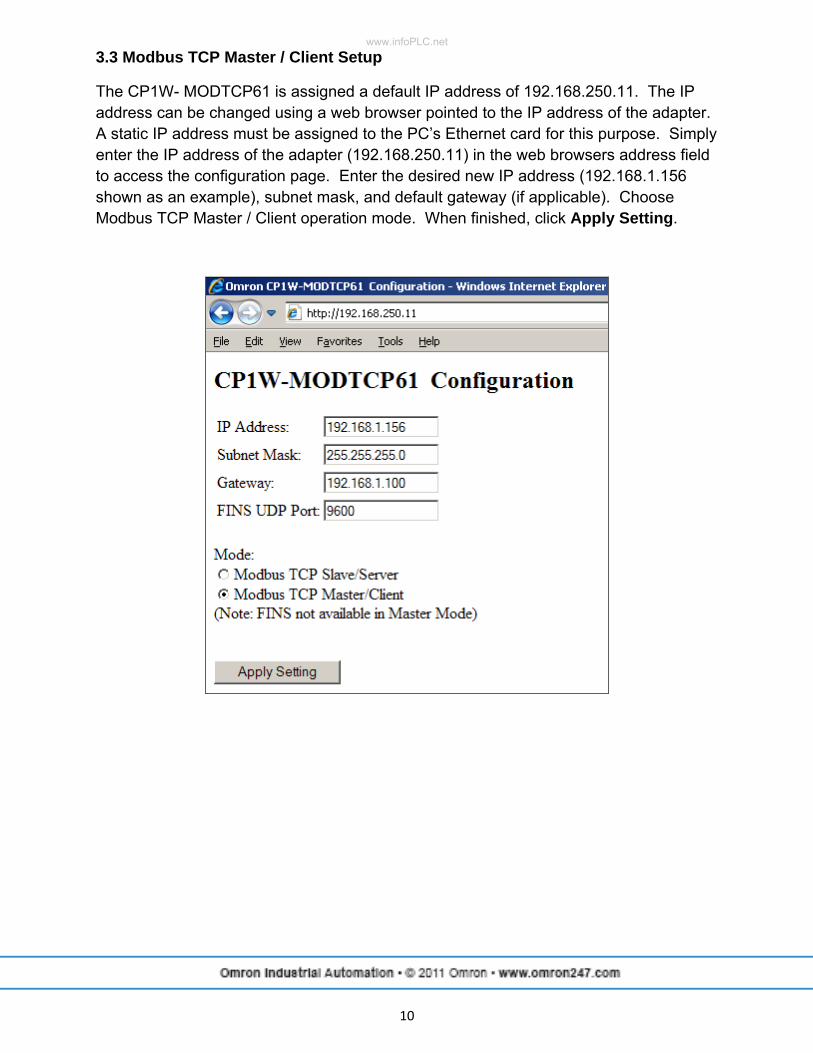
The CP1W- MODTCP61 is assigned a default IP address of 192.168.250.11. The IP address can be changed using a web browser pointed to the IP address of the adapter. A static IP address must be assigned to the PC’s Ethernet card for this purpose. Simply enter the IP address of the adapter (192.168.250.11) in the web browsers address field to access the configuration page. Enter the desired new IP address (192.168.1.156 shown as an example), subnet mask, and default gateway (if applicable). Choose Modbus TCP Master / Client operation mode. When finished, click Apply Setting.
www.infoPLC.net
11
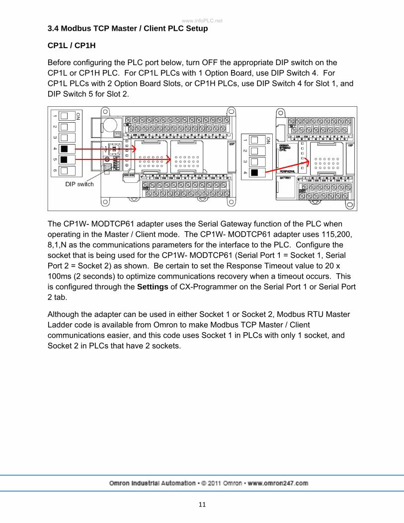
3.4 Modbus TCP Master / Client PLC Setup
CP1L / CP1H
Before configuring the PLC port below, turn OFF the appropriate DIP switch on the CP1L or CP1H PLC. For CP1L PLCs with 1 Option Board, use DIP Switch 4. For CP1L PLCs with 2 Option Board Slots, or CP1H PLCs, use DIP Switch 4 for Slot 1, and DIP Switch 5 for Slot 2.
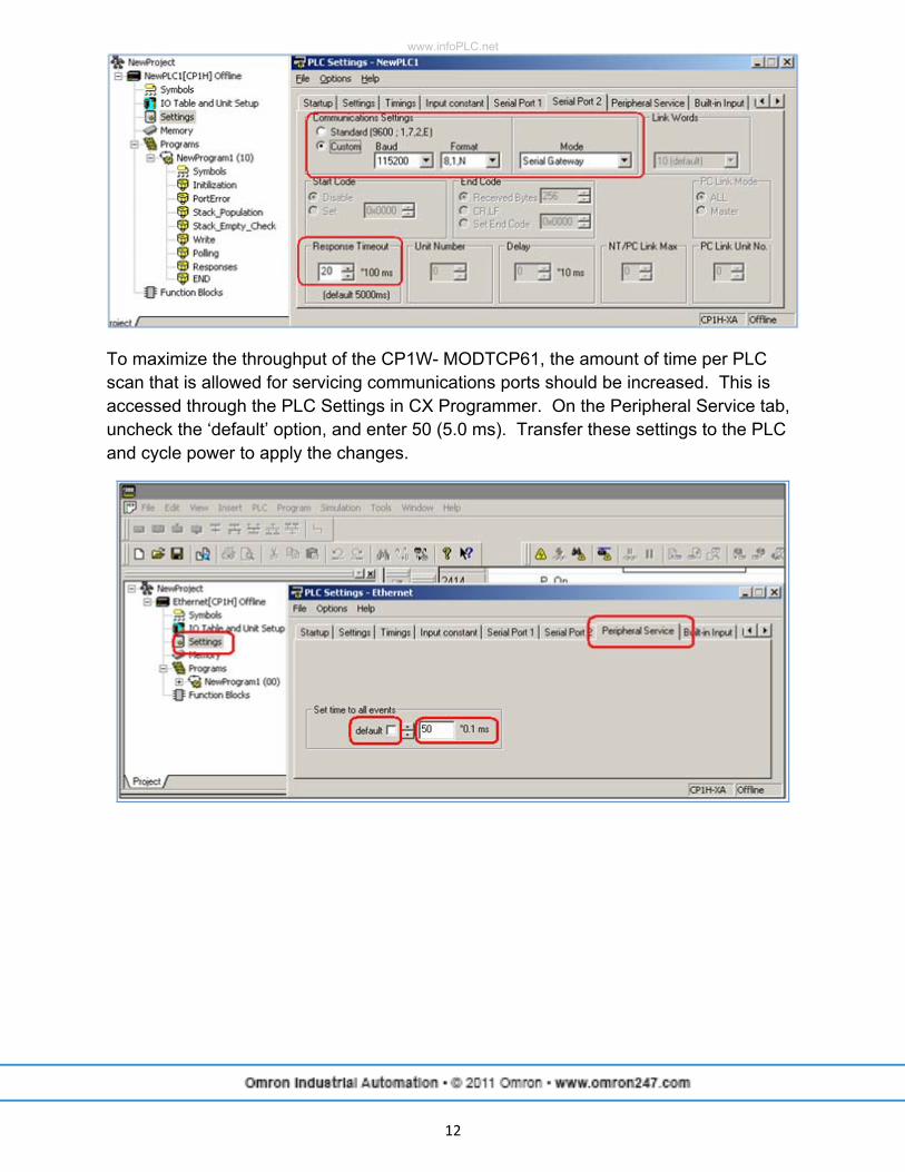
The CP1W- MODTCP61 adapter uses the Serial Gateway function of the PLC when operating in the Master / Client mode. The CP1W- MODTCP61 adapter uses 115,200, 8,1,N as the communications parameters for the interface to the PLC. Configure the socket that is being used for the CP1W- MODTCP61 (Serial Port 1 = Socket 1, Serial Port 2 = Socket 2) as shown. Be certain to set the Response Timeout value to 20 x 100ms (2 seconds) to optimize communications recovery when a timeout occurs. This is configured through the Settings of CX-Programmer on the Serial Port 1 or Serial Port 2 tab.
Although the adapter can be used in either Socket 1 or Socket 2, Modbus RTU Master Ladder code is available from Omron to make Modbus TCP Master / Client communications easier, and this code uses Socket 1 in PLCs with only 1 socket, and Socket 2 in PLCs that have 2 sockets.
www.infoPLC.net
12
To maximize the throughput of the CP1W- MODTCP61, the amount of time per PLC scan that is allowed for servicing communications ports should be increased. This is accessed through the PLC Settings in CX Programmer. On the Peripheral Service tab, uncheck the ‘default’ option, and enter 50 (5.0 ms). Transfer these settings to the PLC and cycle power to apply the changes.
www.infoPLC.net
13
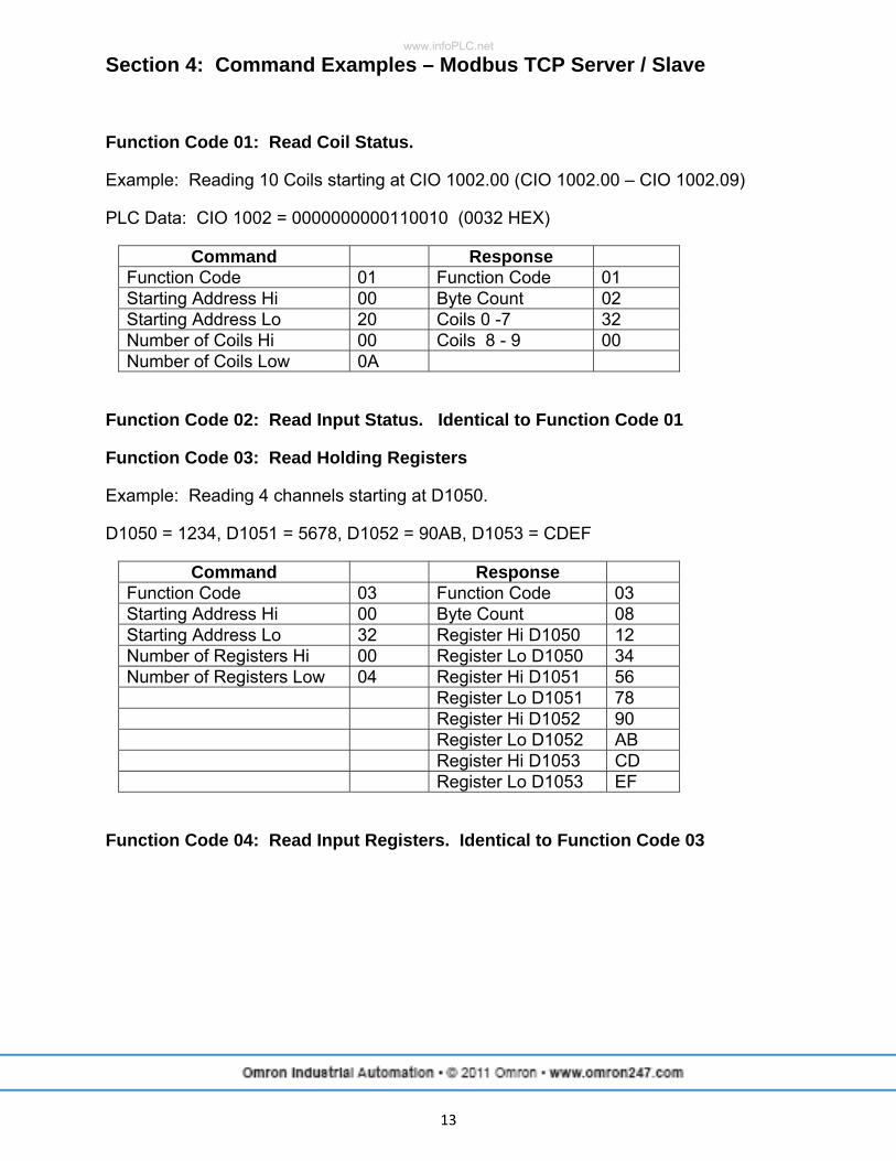
Section 4: Command Examples – Modbus TCP Server / Slave
Function Code 01: Read Coil Status.
Example: Reading 10 Coils starting at CIO 1002.00 (CIO 1002.00 – CIO 1002.09)
PLC Data: CIO 1002 = 0000000000110010 (0032 HEX)
Command Response Function Code 01 Function Code 01 Starting Address Hi 00 Byte Count 02 Starting Address Lo 20 Coils 0 -7 32 Number of Coils Hi 00 Coils 8 - 9 00 Number of Coils Low 0A
Function Code 02: Read Input Status. Identical to Function Code 01
Function Code 03: Read Holding Registers
Example: Reading 4 channels starting at D1050.
D1050 = 1234, D1051 = 5678, D1052 = 90AB, D1053 = CDEF
Command Response Function Code 03 Function Code 03 Starting Address Hi 00 Byte Count 08 Starting Address Lo 32 Register Hi D1050 12 Number of Registers Hi 00 Register Lo D1050 34 Number of Registers Low 04 Register Hi D1051 56 Register Lo D1051 78 Register Hi D1052 90 Register Lo D1052 AB Register Hi D1053 CD Register Lo D1053 EF
Function Code 04: Read Input Registers. Identical to Function Code 03
www.infoPLC.net
14
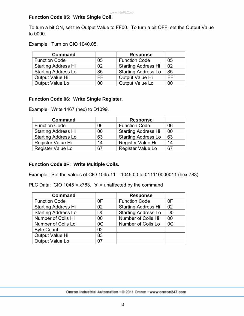
Function Code 05: Write Single Coil.
To turn a bit ON, set the Output Value to FF00. To turn a bit OFF, set the Output Value to 0000.
Example: Turn on CIO 1040.05.
Command Response Function Code 05 Function Code 05 Starting Address Hi 02 Starting Address Hi 02 Starting Address Lo 85 Starting Address Lo 85 Output Value Hi FF Output Value Hi FF Output Value Lo 00 Output Value Lo 00
Function Code 06: Write Single Register.
Example: Write 1467 (hex) to D1099.
Command Response Function Code 06 Function Code 06 Starting Address Hi 00 Starting Address Hi 00 Starting Address Lo 63 Starting Address Lo 63 Register Value Hi 14 Register Value Hi 14 Register Value Lo 67 Register Value Lo 67
Function Code 0F: Write Multiple Coils.
Example: Set the values of CIO 1045.11 – 1045.00 to 011110000011 (hex 783)
PLC Data: CIO 1045 = x783. ‘x’ = unaffected by the command
Command Response Function Code 0F Function Code 0F Starting Address Hi 02 Starting Address Hi 02 Starting Address Lo D0 Starting Address Lo D0 Number of Coils Hi 00 Number of Coils Hi 00 Number of Coils Lo 0C Number of Coils Lo 0C Byte Count 02 Output Value Hi 83 Output Value Lo 07
www.infoPLC.net
15
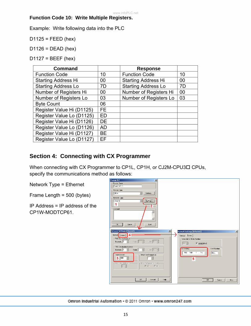
Function Code 10: Write Multiple Registers.
Example: Write following data into the PLC
D1125 = FEED (hex)
D1126 = DEAD (hex)
D1127 = BEEF (hex)
Command Response Function Code 10 Function Code 10 Starting Address Hi 00 Starting Address Hi 00 Starting Address Lo 7D Starting Address Lo 7D Number of Registers Hi 00 Number of Registers Hi 00 Number of Registers Lo 03 Number of Registers Lo 03 Byte Count 06 Register Value Hi (D1125) FE Register Value Lo (D1125) ED Register Value Hi (D1126) DE Register Value Lo (D1126) AD Register Value Hi (D1127) BE Register Value Lo (D1127) EF
Section 4: Connecting with CX Programmer
When connecting with CX Programmer to CP1L, CP1H, or CJ2M-CPU3 CPUs, specify the communications method as follows:
Network Type = Ethernet
Frame Length = 500 (bytes)
IP Address = IP address of the CP1W-MODTCP61.
www.infoPLC.net
16
Section 5: Additional Literature
Additional literature can be obtained from www.omron247.com.
R08I CP1 Series Brochure
W450 CP1H Operation Manual
W451 CP1L / CP1H Programming Manual
W462 CP1L Operation Manual
W472 CJ2 Hardware Users Manual
W473 CJ2 Software Users Manual
V227 W4S Ethernet Switch
www.infoPLC.net
Terms and Conditions of Sale1. Offer; Acceptance. These terms and conditions (these "Terms") are deemed
part of all quotes, agreements, purchase orders, acknowledgments, price lists,catalogs, manuals, brochures and other documents, whether electronic or inwriting, relating to the sale of products or services (collectively, the "Products")by Omron Electronics LLC and its subsidiary companies (“Omron”). Omronobjects to any terms or conditions proposed in Buyer’s purchase order or otherdocuments which are inconsistent with, or in addition to, these Terms.
2. Prices; Payment Terms. All prices stated are current, subject to change with-out notice by Omron. Omron reserves the right to increase or decrease priceson any unshipped portions of outstanding orders. Payments for Products aredue net 30 days unless otherwise stated in the invoice.
3. Discounts. Cash discounts, if any, will apply only on the net amount of invoicessent to Buyer after deducting transportation charges, taxes and duties, and willbe allowed only if (i) the invoice is paid according to Omron’s payment termsand (ii) Buyer has no past due amounts.
4. Interest. Omron, at its option, may charge Buyer 1-1/2% interest per month orthe maximum legal rate, whichever is less, on any balance not paid within thestated terms.
5. Orders. Omron will accept no order less than $200 net billing. 6. Governmental Approvals. Buyer shall be responsible for, and shall bear all
costs involved in, obtaining any government approvals required for the impor-tation or sale of the Products.
7. Taxes. All taxes, duties and other governmental charges (other than generalreal property and income taxes), including any interest or penalties thereon,imposed directly or indirectly on Omron or required to be collected directly orindirectly by Omron for the manufacture, production, sale, delivery, importa-tion, consumption or use of the Products sold hereunder (including customsduties and sales, excise, use, turnover and license taxes) shall be charged toand remitted by Buyer to Omron.
8. Financial. If the financial position of Buyer at any time becomes unsatisfactoryto Omron, Omron reserves the right to stop shipments or require satisfactorysecurity or payment in advance. If Buyer fails to make payment or otherwisecomply with these Terms or any related agreement, Omron may (without liabil-ity and in addition to other remedies) cancel any unshipped portion of Prod-ucts sold hereunder and stop any Products in transit until Buyer pays allamounts, including amounts payable hereunder, whether or not then due,which are owing to it by Buyer. Buyer shall in any event remain liable for allunpaid accounts.
9. Cancellation; Etc. Orders are not subject to rescheduling or cancellationunless Buyer indemnifies Omron against all related costs or expenses.
10. Force Majeure. Omron shall not be liable for any delay or failure in deliveryresulting from causes beyond its control, including earthquakes, fires, floods,strikes or other labor disputes, shortage of labor or materials, accidents tomachinery, acts of sabotage, riots, delay in or lack of transportation or therequirements of any government authority.
11. Shipping; Delivery. Unless otherwise expressly agreed in writing by Omron:a. Shipments shall be by a carrier selected by Omron; Omron will not drop ship
except in “break down” situations.b. Such carrier shall act as the agent of Buyer and delivery to such carrier shall
constitute delivery to Buyer;c. All sales and shipments of Products shall be FOB shipping point (unless oth-
erwise stated in writing by Omron), at which point title and risk of loss shallpass from Omron to Buyer; provided that Omron shall retain a security inter-est in the Products until the full purchase price is paid;
d. Delivery and shipping dates are estimates only; ande. Omron will package Products as it deems proper for protection against nor-
mal handling and extra charges apply to special conditions.12. Claims. Any claim by Buyer against Omron for shortage or damage to the
Products occurring before delivery to the carrier must be presented in writingto Omron within 30 days of receipt of shipment and include the original trans-portation bill signed by the carrier noting that the carrier received the Productsfrom Omron in the condition claimed.
13. Warranties. (a) Exclusive Warranty. Omron’s exclusive warranty is that theProducts will be free from defects in materials and workmanship for a period oftwelve months from the date of sale by Omron (or such other period expressedin writing by Omron). Omron disclaims all other warranties, express or implied.(b) Limitations. OMRON MAKES NO WARRANTY OR REPRESENTATION,EXPRESS OR IMPLIED, ABOUT NON-INFRINGEMENT, MERCHANTABIL-
ITY OR FITNESS FOR A PARTICULAR PURPOSE OF THE PRODUCTS.BUYER ACKNOWLEDGES THAT IT ALONE HAS DETERMINED THAT THEPRODUCTS WILL SUITABLY MEET THE REQUIREMENTS OF THEIRINTENDED USE. Omron further disclaims all warranties and responsibility ofany type for claims or expenses based on infringement by the Products or oth-erwise of any intellectual property right. (c) Buyer Remedy. Omron’s sole obli-gation hereunder shall be, at Omron’s election, to (i) replace (in the formoriginally shipped with Buyer responsible for labor charges for removal orreplacement thereof) the non-complying Product, (ii) repair the non-complyingProduct, or (iii) repay or credit Buyer an amount equal to the purchase price ofthe non-complying Product; provided that in no event shall Omron be responsi-ble for warranty, repair, indemnity or any other claims or expenses regardingthe Products unless Omron’s analysis confirms that the Products were prop-erly handled, stored, installed and maintained and not subject to contamina-tion, abuse, misuse or inappropriate modification. Return of any Products byBuyer must be approved in writing by Omron before shipment. Omron Compa-nies shall not be liable for the suitability or unsuitability or the results from theuse of Products in combination with any electrical or electronic components,circuits, system assemblies or any other materials or substances or environ-ments. Any advice, recommendations or information given orally or in writing,are not to be construed as an amendment or addition to the above warranty.See http://www.omron247.com or contact your Omron representative for pub-lished information.
14. Limitation on Liability; Etc. OMRON COMPANIES SHALL NOT BE LIABLEFOR SPECIAL, INDIRECT, INCIDENTAL, OR CONSEQUENTIAL DAMAGES,LOSS OF PROFITS OR PRODUCTION OR COMMERCIAL LOSS IN ANYWAY CONNECTED WITH THE PRODUCTS, WHETHER SUCH CLAIM ISBASED IN CONTRACT, WARRANTY, NEGLIGENCE OR STRICT LIABILITY.Further, in no event shall liability of Omron Companies exceed the individualprice of the Product on which liability is asserted.
15. Indemnities. Buyer shall indemnify and hold harmless Omron Companies andtheir employees from and against all liabilities, losses, claims, costs andexpenses (including attorney's fees and expenses) related to any claim, inves-tigation, litigation or proceeding (whether or not Omron is a party) which arisesor is alleged to arise from Buyer's acts or omissions under these Terms or inany way with respect to the Products. Without limiting the foregoing, Buyer (atits own expense) shall indemnify and hold harmless Omron and defend or set-tle any action brought against such Companies to the extent based on a claimthat any Product made to Buyer specifications infringed intellectual propertyrights of another party.
16. Property; Confidentiality. Any intellectual property in the Products is the exclu-sive property of Omron Companies and Buyer shall not attempt to duplicate itin any way without the written permission of Omron. Notwithstanding anycharges to Buyer for engineering or tooling, all engineering and tooling shallremain the exclusive property of Omron. All information and materials suppliedby Omron to Buyer relating to the Products are confidential and proprietary,and Buyer shall limit distribution thereof to its trusted employees and strictlyprevent disclosure to any third party.
17. Export Controls. Buyer shall comply with all applicable laws, regulations andlicenses regarding (i) export of products or information; (iii) sale of products to“forbidden” or other proscribed persons; and (ii) disclosure to non-citizens ofregulated technology or information.
18. Miscellaneous. (a) Waiver. No failure or delay by Omron in exercising any rightand no course of dealing between Buyer and Omron shall operate as a waiverof rights by Omron. (b) Assignment. Buyer may not assign its rights hereunderwithout Omron's written consent. (c) Law. These Terms are governed by thelaw of the jurisdiction of the home office of the Omron company from whichBuyer is purchasing the Products (without regard to conflict of law princi-ples). (d) Amendment. These Terms constitute the entire agreement betweenBuyer and Omron relating to the Products, and no provision may be changedor waived unless in writing signed by the parties. (e) Severability. If any provi-sion hereof is rendered ineffective or invalid, such provision shall not invalidateany other provision. (f) Setoff. Buyer shall have no right to set off any amountsagainst the amount owing in respect of this invoice. (g) Definitions. As usedherein, “including” means “including without limitation”; and “Omron Compa-nies” (or similar words) mean Omron Corporation and any direct or indirectsubsidiary or affiliate thereof.
Certain Precautions on Specifications and Use1. Suitability of Use. Omron Companies shall not be responsible for conformity
with any standards, codes or regulations which apply to the combination of theProduct in the Buyer’s application or use of the Product. At Buyer’s request,Omron will provide applicable third party certification documents identifyingratings and limitations of use which apply to the Product. This information byitself is not sufficient for a complete determination of the suitability of the Prod-uct in combination with the end product, machine, system, or other applicationor use. Buyer shall be solely responsible for determining appropriateness ofthe particular Product with respect to Buyer’s application, product or system.Buyer shall take application responsibility in all cases but the following is anon-exhaustive list of applications for which particular attention must be given:(i) Outdoor use, uses involving potential chemical contamination or electricalinterference, or conditions or uses not described in this document.(ii) Use in consumer products or any use in significant quantities. (iii) Energy control systems, combustion systems, railroad systems, aviationsystems, medical equipment, amusement machines, vehicles, safety equip-ment, and installations subject to separate industry or government regulations. (iv) Systems, machines and equipment that could present a risk to life or prop-erty. Please know and observe all prohibitions of use applicable to this Prod-uct. NEVER USE THE PRODUCT FOR AN APPLICATION INVOLVING SERIOUSRISK TO LIFE OR PROPERTY OR IN LARGE QUANTITIES WITHOUTENSURING THAT THE SYSTEM AS A WHOLE HAS BEEN DESIGNED TO
ADDRESS THE RISKS, AND THAT THE OMRON’S PRODUCT IS PROP-ERLY RATED AND INSTALLED FOR THE INTENDED USE WITHIN THEOVERALL EQUIPMENT OR SYSTEM.
2. Programmable Products. Omron Companies shall not be responsible for theuser’s programming of a programmable Product, or any consequence thereof.
3. Performance Data. Data presented in Omron Company websites, catalogsand other materials is provided as a guide for the user in determining suitabil-ity and does not constitute a warranty. It may represent the result of Omron’stest conditions, and the user must correlate it to actual application require-ments. Actual performance is subject to the Omron’s Warranty and Limitationsof Liability.
4. Change in Specifications. Product specifications and accessories may bechanged at any time based on improvements and other reasons. It is our prac-tice to change part numbers when published ratings or features are changed,or when significant construction changes are made. However, some specifica-tions of the Product may be changed without any notice. When in doubt, spe-cial part numbers may be assigned to fix or establish key specifications foryour application. Please consult with your Omron’s representative at any timeto confirm actual specifications of purchased Product.
5. Errors and Omissions. Information presented by Omron Companies has beenchecked and is believed to be accurate; however, no responsibility is assumedfor clerical, typographical or proofreading errors or omissions.
www.infoPLC.net

OMRON CANADA, INC. • HEAD OFFICEToronto, ON, Canada • 416.286.6465 • 866.986.6766 • www.omron247.com
OMRON ELECTRONICS DE MEXICO • HEAD OFFICEMéxico DF • 52.55.59.01.43.00 • 001.800.556.6766 • [email protected]
OMRON ELECTRONICS DE MEXICO • SALES OFFICEApodaca, N.L. • 52.81.11.56.99.20 • 001.800.556.6766 • [email protected]
OMRON ELETRÔNICA DO BRASIL LTDA • HEAD OFFICESão Paulo, SP, Brasil • 55.11.2101.6300 • www.omron.com.br
OMRON ARGENTINA • SALES OFFICECono Sur • 54.11.4783.5300
OMRON CHILE • SALES OFFICESantiago • 56.9.9917.3920
OTHER OMRON LATIN AMERICA SALES54.11.4783.5300
OMRON INDUSTRIAL AUTOMATION • THE AMERICAS HEADQUARTERSSchaumburg, IL USA • 847.843.7900 • 800.556.6766 • www.omron247.com
OMRON EUROpE B.V. • Wegalaan 67-69, NL-2132 JD, Hoofddorp, The Netherlands. • Tel: +31 (0) 23 568 13 00Fax: +31 (0) 23 568 13 88 • www.industrial.omron.eu
Cat. No. SG_CP1_MODTCP 07/11 Note: Specifications are subject to change. © 2011 Omron Electronics LLC Printed in U.S.A.
www.infoPLC.net