CoverF10 - Bucket Elevators
46
F10 Manual Safety, Installation, Maintenance, Operation & Parts Model: ______________ S.N.: _______________ Date: _______________ Part # 41947 For Parts or Service Contact: Universal Industries, Inc. 5800 Nordic Drive P.O. Box 308 Cedar Falls, IA 50613-0308 Phone: (319) 277-7501 Fax: (319) 277-2318
Transcript of CoverF10 - Bucket Elevators

F10Manual
Safety, Installation, Maintenance,Operation & Parts
Model: ______________
S.N.: _______________
Date: _______________
Part # 41947
For Parts or Service Contact:
Universal Industries, Inc.5800 Nordic Drive P.O. Box 308 Cedar Falls, IA 50613-0308
Phone: (319) 277-7501 Fax: (319) 277-2318

F10 i Feb. 1, 2010 ed.
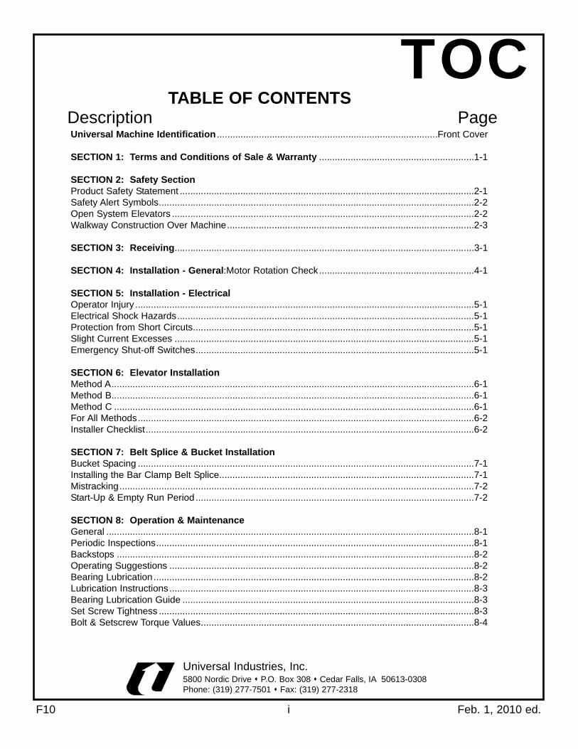
TABLE OF CONTENTSDescription Page
Universal Industries, Inc.5800 Nordic Drive P.O. Box 308 Cedar Falls, IA 50613-0308Phone: (319) 277-7501 Fax: (319) 277-2318
Universal Machine Identification ....................................................................................Front Cover
SECTION 1: Terms and Conditions of Sale & Warranty ...........................................................1-1
SECTION 2: Safety SectionProduct Safety Statement ................................................................................................................2-1Safety Alert Symbols........................................................................................................................2-2Open System Elevators ...................................................................................................................2-2Walkway Construction Over Machine..............................................................................................2-3
SECTION 3: Receiving..................................................................................................................3-1
SECTION 4: Installation - General:Motor Rotation Check...........................................................4-1
SECTION 5: Installation - ElectricalOperator Injury .................................................................................................................................5-1Electrical Shock Hazards.................................................................................................................5-1Protection from Short Circuts...........................................................................................................5-1Slight Current Excesses ..................................................................................................................5-1Emergency Shut-off Switches..........................................................................................................5-1
SECTION 6: Elevator InstallationMethod A..........................................................................................................................................6-1Method B..........................................................................................................................................6-1Method C .........................................................................................................................................6-1For All Methods................................................................................................................................6-2Installer Checklist.............................................................................................................................6-2
SECTION 7: Belt Splice & Bucket InstallationBucket Spacing ................................................................................................................................7-1Installing the Bar Clamp Belt Splice.................................................................................................7-1Mistracking.......................................................................................................................................7-2Start-Up & Empty Run Period ..........................................................................................................7-2
SECTION 8: Operation & MaintenanceGeneral ............................................................................................................................................8-1Periodic Inspections.........................................................................................................................8-1Backstops ........................................................................................................................................8-2Operating Suggestions ....................................................................................................................8-2Bearing Lubrication..........................................................................................................................8-2Lubrication Instructions....................................................................................................................8-3Bearing Lubrication Guide ...............................................................................................................8-3Set Screw Tightness ........................................................................................................................8-3Bolt & Setscrew Torque Values........................................................................................................8-4
TOC

TOCTABLE OF CONTENTS
Universal Industries, Inc.5800 Nordic Drive P.O. Box 308 Cedar Falls, IA 50613-0308Phone: (319) 277-7501 Fax: (319) 277-2318
SECTION 9: AVC-Air Cleanout Operation, Optional EquipmentAVC Operation .................................................................................................................................9-1Air Cycling AVC Operation...............................................................................................................9-1Vacuum Cleanout Operation............................................................................................................9-2Boot Adjustments .............................................................................................................................9-3Removing of Existing Parts..............................................................................................................9-3Modification to Existing Boot............................................................................................................9-3Attaching/Assembling of the Air Vacuum Clean-out Equipment ......................................................9-4Parts Diagram..................................................................................................................................9-5Parts List ..........................................................................................................................................9-6
SECTION 10: Problem Diagnosis:Troubleshooting ...................................................................10-1
SECTION 11: General SpecificationsSpecifications .................................................................................................................................11-1Dimensional Drawing ....................................................................................................................11-2Parts Diagram ................................................................................................................................11-3Parts List ........................................................................................................................................11-4Belt, Buckets, Etc. ..........................................................................................................................11-5Optional Equipment........................................................................................................................11-6Parts List #2 Drive..........................................................................................................................11-7Parts Diagram, Lockable Disconnect Switch .................................................................................11-8Parts Diagram & List, Service Platform..........................................................................................11-9Parts Diagram & List, Consignor Platform ..................................................................................11-11Parts Diagram & List, Rest Platform ............................................................................................11-12Parts Diagram, Decals .................................................................................................................11-14Parts List, Decals .........................................................................................................................11-15
SECTION 12: Sources of Standards & Codes .........................................................................12-1
SECTION 13: Personnel Check Off Form .................................................................................13-1
SECTION 14: Index .....................................................................................................................14-1
F10 ii Feb. 1, 2010 ed.

TERMS AND CONDITIONS OF SALE9. MANUALS: Seller will furnish one combined safety, installation,operation, maintenance, and parts manual. Extra manuals will besent on request.
10. SHIPMENT: Shipment may be by carrier or other means select-ed by Seller. All units are shipped-knocked down. If shipment isdelayed by Buyer, date of readiness for shipment shall be deemedto be date of shipment for payment purposes. If manufacture isdelayed by Buyer, a payment shall be made based on purchaseprice and percentage of completion, balance payable in accordancewith the terms as stated. Equipment held for Buyer shall be at therisk and expense of Buyer.
11. LIMITED WARRANTY: Seller warrants that the components andparts that it manufactures for its machines and equipment will befree from defects in material or workmanship for a period of one (1)year from the date of shipment by Seller. Seller does not warrantany component or part not manufactured by Seller. If, during theone year warranty period, Buyer discovers a defect in material orworkmanship of a covered component, Buyer shall promptly (and inno event later than thirteen (13) months after the date of shipmentby Seller) notify Seller in writing of such defect. Within a reasonabletime of receiving such notification, Seller will furnish a replacementcomponent or part. Buyer shall be responsible for all expensesattendant to the shipment and installation of the replacement compo-nent or part. Buyer also shall be responsible for returning the defec-tive component or part to Seller if request by Seller to do so. THEFOREGOING WARRANTY IS IN LIEU OF ALL OTHER WAR-RANTIES, EXPRESSED OR IMPLIED, SELLER DISCLAIMS THEIMPLIED WARRANTY OR MERCHANTABILITY AND ANY IMPLIEDWARRANTY OF FITNESS FOR A PARTICULAR PURPOSE.
SELLER SPECIFICALLY DOES NOT WARRANT PARTS ANDCOMPONENTS PURCHASED BY SELLER FROM THIRD PARTYSUPPLIERS, INCLUDING, BUT NOT LIMITED TO, SUCH PARTSAND COMPONENTS AS MOTORS, BEARINGS, REDUCERES,AND SWITCHES. BUYER SHALL BE LIMITED IN RECOURSEFOR SUCH COMPONENTS AND PARTS TO THE TERMS OF THEWARRANTY OF THAT PARTICULAR MANUFACTURER.
12. LIMITATION OF REMEDIES AND DAMAGES: Buyer's primaryremedy for breach of warranty is the provision of a replacementcomponent or part, as stated above. If Seller is unable to provide areplacement component or part, Buyer's alternate remedy shall berefund of Buyer's purchase price. These remedies are Buyer's soleand exclusive remedies for breach of warranty. In no event shallSeller be liable under any theory of liability for (i) damages in excessof Buyer's purchase price or (ii) any special, incidental or conse-quential damages.
13. TIME TO BRING SUIT: Buyer shall bring any action relating tothe goods sold by Seller pursuant to his Sales Order or Invoice,including any action for breach of contract or breach of warranty, notlater than two (2) years after the date of shipment by Seller. Buyeragrees that any action brought after such date shall be barred asbeing untimely.
14. PLACE OF BRINGING SUIT: Any action relating to the goodssold by Seller pursuant to this Sales Order or Invoice shall bebrought in the Iowa District Court in and for Black Hawk County,Iowa.
SECTION 11. TERMS OF PAYMENT: Buyer agrees to pay the purchase priceshown on the acknowledged Sales Order in accordance with theterms of payment stated on the Sales Order. Amounts not paidwhen due shall accrue interest at the rate of 1.5% per month fromthe due date. For all sales on open account, the full purchase priceshall be due 30 days from the date of the Invoice. However, Sellerreserves the right to require down payment and/or progress pay-ments, which shall be specified on the Sales Order. Unless other-wise specified, all sales are exclusive of freight, taxes, and otheramounts due third parties. Discounts for early payment shall be asstated on the Invoice. Discounts shall not apply to the amount ofany freight, taxes of other sums due any third party. Terms begin onthe date of the Invoice. Seller shall establish the credit terms avail-able to Buyer based on a current credit application and any otherinformation available to Seller. At any time, Seller may limit or can-cel the amount or time of credit extended to Buyer, in the sole opin-ion of Seller. Buyer shall pay in cash before delivery (C.O.D) for anyorder or part of an order in excess of the approved credit terms ofBuyer. In the event Buyer fails to pay in advance any amountdemanded by Seller, Seller shall have the right, in addition to anyother remedies available, to cancel the contract or sell all or any partof the undelivered goods without notice at public or private sale,holding Buyer responsible for any deficiency.
2. SECURITY INTEREST: Seller reserves and Buyer hereby grantsto Seller a security interest in the goods shipped under this agree-ment and the proceeds derived from their sale of whatever nature,whether in cash, note or account. This security interest shall contin-ue until the full purchase price and any related expenses and/orcharges due in connection with the Sales Order are paid in full.Notes shall not be considered as payment buy merely as evidenceof indebtedness. Seller shall be entitled to all the rights of a securedparty under Iowa law. Buyer agrees to execute any documentsrequired to perfect or confirm this security interest.
3. TITLE/RISK OF LOSS: Title to all goods priced at shipping pointshall pass to Buyer upon delivery at such shipping point. All risk ofloss shall be Buyer's from the time of shipment. Seller's responsibil-ity for any loss or damage to the goods ceases at the time delivery ismade to the carrier. Buyer shall be solely responsible for makingany claim(s) against the carrier for any loss or damage.
4. EXPORT ORDERS: Prices for export-crating charges can beobtained by contacting the Sales Department for quotations andorders.
5. PRICE CHANGES: The prices listed may be changed by Sellerwithout notice in order to reflect Seller's prices at time of shipmentand any increase in transportation, labor or other costs. If a deliv-ered price has been quoted, any charges at destination for spotting,switching, handling, storage, and other accessorial services anddemurrage shall be borne by Buyer. Seller reserves the right to cor-rect any obvious errors or mistakes in specifications or prices.
6. WHEN ORDERING: Please specify name of item, catalog partnumber, as well as other information when this is applicable to insureprompt handling of the order.
7. MINIMUM BILLING: $50.00 Net, exclusive of transportationcharges.
8. DELIVERIES: Any delivery schedule indicated is based onSeller's present estimate of the time required to ship after receipt ofBuyer's order. In the event of any delay in Seller's performance duein whole or in part to any cause beyond Seller's reasonable control,Seller shall have such additional time for its performance as may bereasonably necessary under the circumstance.
F10 1-1 Feb. 1, 2010 ed.

F10 1-2 Feb. 1, 2010 ed.
15. TOLERANCES AND VARIATIONS: All goods shall be subject totolerances and variations consistent with usual trade practicesregarding dimension, straightness, section, composition andmechanical properties and normal variations in surface and internalconditions and quality and shall also be subject to deviations fromtolerances and variations consistent with practical testing andinspection methods.
16. RETURNS: Returns are not accepted unless Seller is first noti-fied of the reason for the return, and has granted permission for thereturn to be made. A return authorization tag will be issued onagreed-to returns. Credit for permitted returns will not exceed theprice charged when shipment was made, or the market price at thetime the return was received. 20% handling charge will be made onall returned goods. In case of damaged goods, the charge will riseaccordingly. When the cause for return is due to incorrect shipmentby Seller, there will be no restocking or freight charge. Any mer-chandise that is to be returned must be received with a returnauthorization tag attached and freight charges-Prepaid. Any returnsauthorized by Seller are conditioned upon the goods being returnedin condition for resale.
17. COPYRIGHT: No reproduction either in whole or in part may bemade from Seller's catalog, drawings, sketched, etc., without writtenpermission from Seller's Sales Department.
18. BACK ORDERS: Seller will attempt to ship all orders complete;however, in the event of back orders, the orders will be shipped withfreight charges, collect or prepaid, at Seller's option only.
19. SHORTAGES: Claims for shipping shortages concealed or oth-erwise, will not be allowed by Seller, unless reported within 15 daysafter date of shipment by Seller.
20. PRODUCT CHANGES: Seller reserves the right to change,without notice, the design or any modular, "standardized" compo-nents represented in Seller's catalog.
21. TOOLS, DIES AND FIXTURES: Unless otherwise expressly pro-vided herein, any tools, dies, or fixtures which may be developed forSeller in the production of the goods covered hereby shall be ownedby Seller, as Seller may elect, even though Buyer is charged inwhole or in part for the cost of such tools, dies and fixtures.
22. PATENT INFRINGEMENT: If any of the goods are to be fur-nished to Buyer's specification, Buyer agrees to indemnify Seller andSeller's successors and assigns, against all liabilities and expensesresulting from any claim of infringement of any patent in connectionwith the production of such goods.
23. SPECIAL DRAWING OR DATE REQUIREMENTS: Seller willprovide, upon request, an 8 ½ x 11 copy of any line drawing shownin the catalog without charge. Seller reserves the right to reject anyrequest and/or assess a charge for any other drawing.
24. CANCELLATION: Except as otherwise provided in Paragraph 1,order may be cancelled or modified only by written agreementbetween the parties. On specially ordered or fabricated equipment,no cancellation will be allowed. Buyer's insistence upon cancellingor suspending fabrication or shipment, or Buyer's failure to furnishspecifications when required, may be treated by Seller as a breachof contract by Buyer, and Seller may cancel any unshipped balancewithout prejudice to any other remedies Seller may have.
25. TAXES: All applicable federal, state or local sales, use, occupa-tional or excise taxes are the responsibility of the Buyer and shall bein addition to the price or prices stated unless otherwise specificallystated. Seller shall have the right to Invoice separately any such taxas may be imposed at a later time. Applicable tax exemption certifi-cates must accompany any order to which the same applies.
26. MODIFICATIONS OF ALTERATIONS TO EQUIPMENT: Sellershall not be liable for any product that is modified or altered by Buyeror it's assignee or successor regardless of whether Seller knows oris aware of such modification or alteration.
27. EQUIPMENT OPERATION: Buyer agrees to require its employ-ees to read and be familiar with the safety instructions and the oper-ation and maintenance portion of the manual before operating thisequipment. Buyer agrees to require its employees to use all safetydevices and guards on the equipment and to use safe operating pro-cedures. Buyer agrees to not remove or modify any such equip-ment, switch, device, guard or warning sign. If Buyer, or its employ-ees, fail to strictly observe all of these obligations, Buyer agrees toindemnify and save Seller harmless form any liability or obligationincurred by Seller to persons injured directly or indirectly by the oper-ation of the equipment.
28. RESALE, TRANSFER, OR LEASE OF EQUIPMENT TO OTH-ERS: Buyer agrees to the continuing obligation to notify Seller of theresale, transfer or lease of the equipment to third parties, stating thename and address of the new owner or transferee and the locationof the equipment.
29. REPORTING PERSONAL INJURIES OR PROPERTY DAMAGE:The Buyer or user agrees to notify Seller within 30 days of any acci-dent or occurrence involving Seller's machinery or equipment result-ing in personal injury or property damage, and shall cooperate fullywith Seller in investigating and determining the cause of such acci-dent or occurrence. In the event that the Buyer or user fails to givesuch notice to Seller and so cooperate, the Buyer or user agrees toindemnify and save Seller harmless from all loss or damage arisingfrom such accident or occurrence.
30. ASSIGNABILITY: Any contract for sale and purchase of machin-ery and equipment cannot be assigned except with the written con-sent of Seller.
31. SUCCESSOR OWNERS AND USERS: The terms and condi-tions hereof are binding on successor owners and users, who takeby purchase, assignment, lease, or otherwise, the right to own, useor operate the equipment sold to the original Buyer, and said termsand conditions shall transfer with the equipment itself as an integralobligation of any successor to the original Buyer. The successorowner and user obligations and liabilities stated herein shall alsoapply if the original Buyer was a dealer and purchased the equip-ment from Seller for purposes of resale and transfer to third parties.
32. ENTIRE AGREEMENT: These Terms and Conditions of Saleconstitute the entire agreement between the parties concerning anymachinery or equipment sold and purchased. It shall not be modi-fied or cancelled except by mutual agreement in writing signed byall parties.
33. APPLICABLE LAW: The laws of the state of Iowa shall governand control the rights, duties, remedies, and obligations of Seller,Buyer, successors, user, and owner and Iowa law shall be used tointerpret and construe all of the terms and conditions hereof.
SECTION 1

F10 2-1 Feb. 1, 2010 ed.
UNIVERSAL INDUSTRIES, INC. PRODUCT SAFETY STATEMENT
To: Customers, Dealers, Owners, and Users
Universal Industries, Inc. strives to make its products safe. However, because of the
wide variety of applications for its products, often Universal does not know how the equipment
is being used and installed. Consequently, Universal cannot directly control the installation of
its product to assure compliance with applicable safety codes and practices. Nevertheless,
Universal has listed various safety codes, standards, and regulations in its Manuals to assist
the owner-user in providing a safe installation.
Universal will continue its best efforts to design, build, and market a safe product, and
will continue to advocate and urge a safe installation of that product.
Universal requests your written suggestions as to how its product could be manufactured
to improve its safety, convenience of use, function, repair, and maintenance. Written
suggestions should be dated, signed, and mailed to:
Product Safety and PlanningUniversal Industries, Inc.
P.O. Box 308Cedar Falls, Iowa 50613
PRODUCT SAFETY STATEMENTSECTION 2

F10 2-2 Feb. 1, 2010 ed.
This is a safety alert symbol and is used in this manual and on signs placed on the machine to callattention to specific safety precautions.
The following words are signal words. Signal words have specific meaning when used with this symbol.
Denotes a general reminder of good safety practices or to direct attention to unsafe practices which, couldresult in personal injury if proper precautions are not taken.
Denotes specific potential hazard, which can result in injury or death if proper precautions are not taken.
Denotes the most serious specific potential hazard, which would result in high probability of death or irreparableinjury if proper precautions are not taken.
All machines have inherent hazards such as moving parts, energy (electrical, mechanical or hydraulic), sharp edgesand fumes or dust. Personnel must keep clear of moving machinery. Only authorized and trained persons are to beinvolved in the operation of this machine. Any disregard for instructions and safety precautions can cause seri-ous injury or death.
Guards, disconnects, lock-outs and other features are provided or are available to improve operator safety.
This machine must not be altered in any manner or operated with any damaged, missing, or malfunctioningparts. If modification is deemed necessary to accomplish the user's requirements, write or FAX a descriptionincluding a sketch or drawing to the Company describing the changes or new uses desired. Include themachine identifications, condition and any previous modifications. The company may be able to help the customer avoid creating a hazardous situation. Careful attention must be given to adjacent machinery andaccessible space for cleaning and inspection. Other factors should be planned for such as: product spillage,dust pollution, personnel space, interfacing of machines, automatic startup, and handling of hot materials.
SAFETY ALERT SYMBOLS
CAUTION
WARNING
DANGER
THE FREQUENT USAGE OF ELEVATORS AND CONVEYORS TOGETHER WITH THE NECESSARY CONNECTIONBETWEEN THEM MAKES IT ADVISABLE TO ADDRESS THE SAFETY CONSIDERATIONS OF BOTH UNITS EVENTHOUGH THE READER MIGHT BE DEALING ONLY WITH AN ELEVATOR OR ONLY A CONVEYOR.
INSTRUCTIONS AND WARNING FOR USE OF COVER OR GRATE ON OPEN SYSTEM ELEVATORS
The company recommends that for safety reasons its elevator and/or hopper be closed or covered during the time it isin operation.
The company cannot know all the applications of its elevators by its customers, but recognizes that there may be someapplications where the material being elevated or conveyed requires that there be an open system. (Open system iswhen the hopper is exposed and open to view and to bodily parts during operation).
The purchaser and/or user is instructed and warned that the handling of certain materials may call for the use of anopen system. Thus requiring the use of certain grates or guards to prevent persons from using or operating the unit andcoming in contact with the moving parts, thereby sustaining serious bodily injuries or death.
When such an open system is to be operated, the purchaser or user is referred to ANSI or OSHA Regulations inSection 12 of this manual which may be applicable to the improved safety for the operator.
WARNING
SECTION 2

F10 2-3 Feb. 1, 2010 ed.
FAILURE TO FOLLOW THESE INSTRUCTIONS COULD RESULT IN SEVERE INJURY OR DEATH
CONSTRUCTION OF WALKWAY OVER CONVEYOR AND/OR ELEVATOR INLET
The Company assumes that personnel or the operator will not step on, across, or over the conveyor or elevatorinlet while it is stopped or running. The Company also places a Warning Sign on the conveyor and elevator inletto warn against such acts.
The user, however, may have a unique and particular usage that requires the operator of the conveyor or elevatorto cross over the unit. Whether the conveyor or elevator is running or stopped, if such a usage is anticipated ornecessary to accomplish the users' purpose, a permanent guarded walkway should first be constructed over andacross the conveyor or elevator inlet in accordance with OSHA and other appropriate standards and regulations.Conveyors and elevator inlets should be crossed only at these designated points.
SAFETY
WARNINGSECTION 2

F10 3-1 Feb. 1, 2010 ed.
Plan for and provide adequate lifting and moving equipment for safe unloading of heavy, bulky machine subassemblies.
Allow enough time for personnel to safely unload the machinery. Do not allow inclement weather or the pressure ofinstallation schedules to unduly hurry the unloading and check-in process.
Immediately check goods received against the bill of lading and packing list, making note of those items that may havebeen back ordered.
Inspect boxes, crates and machinery for damage. Notify freight carrier immediately of missing pieces or damageclaims. Open boxes and examine contents for completeness of order and/or damage. The buyer must handle claimsfor loss or damage in transit with the carrier. (See Terms and Condition of Sale)
Have an experienced machine assembler or millwright look over the goods to assess possible damage, missing partsand to estimate the kind of equipment and methods required for assembly.
Find the manual holder on the unit and remove the manual. If necessary, order from the Company more copies forother departments or users of this machine. Refer to Section 12 of this manual for various Safety Standards andCodes. The back cover also lists addresses where this manual may be obtained.
WARNINGREAD THE SAFETY SECTION! FAILURE TO FOLLOW SAFETY MESSAGES COULD RESULT IN SEVERE
INJURY OR DEATH.
RECEIVINGSECTION 3

F10 4-1 Feb. 1, 2010 ed.
Read the entire manual, especially the safety instructions. Study the drawings and specifications to gain anunderstanding as to how the parts go together. Most machines are shipped partially assembled and require further assembly with the aid of cranes, hoists, "come-alongs", drift punches for bolt hole alignment, clamps, weld-ing equipment, and experienced assembly supervision.
WARNING
FAILURE TO HEED ABOVE SAFE PRACTICES COULD RESULT IN SEVERE INJURY OR DEATH.
INSTALLATION - GENERAL
Do not attempt to assemble, hoist into place, or hook up machines with untrained personnel orinadequate tools and equipment. To do so invites wasted time, causes unnecessary repairs andjeopardizes the safety of all persons associated with the project. Use experienced millwrights orriggers!
It is often necessary to connect the electrical supply to the motor in a temporary manner to check the direction ofmotor shaft rotation. Upon completion, if needed, reconnect, and recheck the rotational direction before makingpermanent connections.
DO SO WITH MOTOR DISCONNECTED FROM THE DRIVE AND THE REST OF THE MACHINE IF AT ALLPOSSIBLE.
To check direction of motor rotation:1. Warn all personnel working in the area and on electrically connected machines (possibly out of the area) that a
test is pending.2. Post observer(s) or provide for fail-safe communications between the motor location and the electrical switch.3. If motor is disconnected from drive, take care to restrain the motor from rolling at the start due to inertial
reaction. Take special care with the C-face type motor which has no mounting foot and almost a round casing. While this reaction may not be violent, if the C-face motor was insecurely resting on a ledge or support, it could roll off, creating a falling hazard.
4. If motor cannot be disconnected from the drive or the drive disconnected from the machine, be sure the machine is clear of tools, parts, and bolts and that all personnel are cleared away at a safe distance from the machine.
All guards, covers, safety signs, overload devices are to be in place and functional before starting initial run-in(empty operation) or before placing unit in service.
WARNING
SECTION 4

F10 5-1 Issued 2009
REQUIREMENTSNational and local Electrical Codes have had as their main goal, the SAFE OPERATION OF EQUIPMENT. They canhelp you eliminate the risk of injury or equipment damage, but only if you follow them under the guidance of your localelectrical inspector or qualified journeyman electrician.
There are four main areas of Electrical Safety:1. Safeguarding the operator from physical injury by the equipment itself.2. Safeguarding the operator from electrical shock injuries.3. Safeguarding the wires and equipment from major current damage due to short circuits.4. Safeguarding the operator from slightly excessive electrical current levels that can still cause fires and equipment
damage.All four areas are important and require careful planning before installation is begun.
First Area of Safety-Operator InjuryRequires the physical guarding of all moving parts of the equipment. Electrical disconnect switches should be padlocked in the off position before work is started. Emergency stop switchesshould always be installed near open areas to minimize injuries from accidental contact with moving material orequipment parts. Most importantly, thorough training of all workers should be done to eliminate the accidents beforethey happen. Training and guarding is required by OSHA. Refer to Section 12 for various regulations that may coverthe specific safety concern.
Second Area of Safety-Electrical Shock HazardsRequires the installation of properly sized and protected wiring and electrical equipment. Code requirements forgrounding should be followed completely, and the entire installation should be reinspected periodically to detect anydeterioration in your overall exposure to these and other risks.
Third Area of Safety-Protection from Short CircuitsRequires the use of properly sized fuses or circuit breakers in each section of the electrical distribution system at thesite, from the main disconnect to the motor. At each point, fusing cuts off power to prevent fires, personal injuries, andfurther damage to equipment.
Fourth Area of Safety-Slight Current ExcessesThis area is important because the conditions that cause expensive damage are difficult to detect or prevent with eitherfuses or circuit breakers. Only magnetic starters with correctly sized heaters are sensitive enough to limit current inmany situations. Anything else will allow a motor or its wiring to burn out at slight overloads or low voltage situations.Fuses are just not available in enough different sizes to protect the motor against these smaller overloads. Magneticstarters also can be remotely controlled with switches, including low-speed switches, emergency stop switches, andremote or automatic controls. Besides being REQUIRED BY THE ELECTRICAL CODE, magnetic controls also protectanyone working on the equipment after a power failure as it greatly lessens the chance of an unexpected start whenpower is restored.
INSTALLATION - ELECTRICAL
Unit Application, location and specifications determine the type, quantity and/or placement of electrical, electrical safetyor other safety controls required. Whether another supplier or the Company supplies these controls, all OSHA andhealth standards, the National Electric Code and the Local Codes should be considered.
INSTRUCTIONS FOR PURCHASERS, INSTALLERS, AND DESIGNERS FOR USE OF EMERGENCY SHUT-OFFSWITCHES FOR UNITSThe Company cannot know all the uses and applications of its units, but recommends the installation and use of one ormore emergency shut-off switches on each installation. The emergency shut-off switches improve the safety for theuser, the operator, and other people in the area of the unit. The installer and/or designer will have to analyze theinstallation of each unit, and determine the placement of, location of, and number of emergency switches necessary foreach application and usage. EMERGENCY SHUT-OFF SWITCHES ARE OFFERED BY THE COMPANY IN ITSMANUAL AND SHOULD BE ORDERED AND INSTALLED AS RECOMMENDED BY THE INSTALLER ORDESIGNER.
WARNINGDO NOT INSTALL THIS UNIT WITHOUT A LOCKABLE ELECTRICAL DISCONNECT SWITCH
SECTION 5

F10 6-1 Feb. 1, 2010 ed.
ELEVATOR INSTALLATION
1. Determine the exact location of the elevator boot. Establish the up-leg and down leg sides. Consider how the boot will be cleaned out and serviced when necessary. Establish the location of the lockable disconnect switch for the person who will be cleaning or maintaining the machine. Refer to OSHA Regulation 1910.147 requiring employer to use a lockable disconnect switch.
2. Establish whether the elevator is to be fed on the down leg side or the up-leg side or both. Preferred side is the up-leg side. Experience has shown that fewer feeding problems and less product damage occurs when feeding on the up-leg side. However, lightweight (fluffy) materials load well at low positions on the down-leg side. The low position on the up-leg side is to be used as a last resort and only with free-flowing materials.
Positioning the hopper (inlet) high on the down leg side or low on the up-leg side may result in buckets not fillingto capacity. Feeding on the down-leg side may cause the elevator to consume more power, to damage fragileproducts, and to be more susceptible to choking.
CAUTION
3. Before starting assembly, determine the height at which the access section and the platforms (if any) will be placed. Plan for the location of safety lockout switches and/or emergency stop switches for operating, cleaning, and service personnel.
4. Assemble the elevator and erect according to the three methods listed below. As noted in Section 4, INSTALLATION-GENERAL section of the manual use experienced assembly, millwright or rigger personnel to minimize mistakes and to make the installation as safe as possible.
METHOD AAssemble the elevator completely at ground level (horizontal). Hoist the assembly into position (vertical), using leggingreinforcements, two lift points to distribute the load. If equipped with a ladder, weld the ladder ends together to stiffenthe elevator.
METHOD BAssemble the elevator starting with the boot section and assembling upward. Place access section and differentlegging lengths as desired. Run a cable or rope over the head pulley (top), attach the cable to the belt or belt andbucket assembly and pull the belt into the elevator by pulling down over the head pulley.
METHOD CBolt the head assembly and one or two sections of legging together as a subassembly. Pull the belt around the headpulley. As the unit is lifted with a crane, slip sections of legging over belt ends and bolt into position from underneath.
Be sure buckets are installed for operation in the correct direction!
WARNING
Guy or brace the standing sections of the elevator to prevent swaying or collapse during erection. Attach guysto leg, not ladders or platforms! Use two or three cable clamps per end of guy. Guard against sharp anchorholes cutting the cable by using any practical means including the use of cable thimbles. Failure of the guysystem may cause serious injury or death.
SECTION 6

F10 6-2 Feb. 1, 2010 ed.
ELEVATOR INSTALLATIONFOR ALL METHODS: Brace the head section permanently when erection is complete. Guy or brace the elevators at 20 to 30 foot intervalsbelow the head section, using 5/16 inch or 7/16 inch diameter galvanized wire rope. The top guys should make anangle of at least 30 degrees or more with the trunking and be guyed in four equally spread directions. Align the outeredges of the trunk coupling to assure that the buckets will not catch on interior projections. Install bolts (grade 5 orbetter furnished) in all holes provided in coupling. Grade 5 bolts have superior strength and can be identified by theindustry standard three (3) marks on their head.
If required, weather or dust sealant is available from the Company. If the sealant was previously ordered, it wouldhave shipped with the unit. Prior to attaching the next coupling, apply a 1/8" diameter bead of sealant to the trunkingcoupling face.
Use a transit instrument from in two different directions (side and front or back) or a plumb bob. To check the plumband straightness of the finished installation. IT IS IMPORTANT THAT THE ELEVATOR IS PLUMB AND STRAIGHT!A plumb, straight elevator will be more durable, quieter, and less expensive to operate because the contact of thebucket/belt assembly with trunking will be minimized.
INSTALLER CHECKLIST: All guards and covers are in place? Are lockable electrical disconnect switches installed properly? Are all warning signs visible-not painted over or badly scratched? If not, order and install new safety warning signs. Are the set screws tight? (See Section 4). Is the motor wired for correct rotation? (See Section 4) Is the reducer backstop installed to allow correct rotation? (if a backstop is necessary or provided) Does reducer have the correct kind and amount of oil? (See reducer manufacturer's recommendations) Are all of the tools, excess nuts and bolts, and spent welding electrodes, etc., cleared out of the elevator? Are inlet(s) guarded per safety standards, codes and good practice? Deliver this manual to the person responsible for the operation and maintenance of the elevator. Get additional
copies made or order them from the Company. If the installer is a third party, good business practice would be to have a weritten statemnt signed by the installer that this manual exists and was read for installation information and turned over to the permanent owner/operator of the elevator.
LOCK POWER OFF BEFORE CHECKING ABOVE ITEMS. Replace all covers and guards before putting elevatorinto service. Failure to do so may cause serious injury or death.
WARNING
Before running the unit, operate unit empty for several hours. While doing this, recheck the tightness ofbucket bolts, the bar clamp belt splice, bearing and reducer setscrews, pulley fasteners, drive componenttemperatures and signs of normal grease leakage from around bearing seals (a small bead of visible greaseis desirable).
FAILURE TO INSTALL EMERGENCY SHUTOFF SWITCHES MAY CAUSE SERIOUS INJURY OR DEATH.
WARNING
Emergency Stop Switches must be used on all systems.
The Company ships an Emergency Shutoff Switch as standard equipment on all systems.
SECTION 6

F10 7-1 Feb. 1, 2010 ed.
BELT SPLICE & BUCKET INSTALLATION
LOCK POWER OFF IF ASSEMBLING BUCKETS AND PADS TO A BELT ALREADY INSTALLED IN THEELEVATOR.
DANGER
WARNING
Typically, upon installing a new belt, the pads and the buckets are fastened to the belt at ground level near theelevator. Then, the completed assembly is pulled up into the elevator legging. Another method of bucket installation isto pull the belt into the elevator, install splice, and then bolt the pads and buckets onto the belt by working through theaccess section opening. This latter method is similar to a maintenance operation where buckets, bolts, pads and thebelt are examined or parts exchanged.
Elevators that do not have power connected can also be dangerous due to unbalanced belt assembliesrunning away when not sufficiently anchored. Assemble only a few buckets at a time, leaving many spaces orgaps, filling in these empty spaces as they present themselves on succeeding revolutions. Failure to do somay cause serious injury or death due to uneven distribution of weight.Most models have buckets installed on each set of holes. Consult the specifications page in Section 11 in this manualfor the bucket spacing. Be sure buckets are installed to discharge over the down-leg side!
Bucket cushions or washers are provided for installation between the buckets and the belt. Be sure bucket cushionsare placed so their upper edge is even with the top edge of buckets. Tighten the bucket bolts evenly until the bolthead is embedded into the belt. Do not over tighten so that the belt bulges between the bolt heads. A six point deepsocket is the nut runner of choice.
DO NOT USE A LAP-SPLICE OR A BUTT-SPLICE IN A UNIVERSAL ELEVATOR. ALWAYS USE A UNIVERSALBAR-CLAMP SPLICE. FAILURE TO USE THE BAR-CLAMP SPLICE COULD RESULT IN SERIOUS INJURY ORDEATH. Less reliable splices could fail, dropping the belt assembly into the legging, possibly causing legging ruptureand elevator collapse in the case of tall units.
INSTALLING THE BAR-CLAMP BELT SPLICE
BELT SPLICE & BUCKET INSTALLATIONSteps to installing a bar-clamp splice (see illustration).
1. For Boot Take-up Systems: Raise boot pulley to the upper limit of travel of the take-up bolt. For Top Take-up Systems: Lower head pulley to the upper limit of travel of the take-up bolt.
2. Use belt-stretching equipment (if available) to draw the belt tight.3. Pull the ends of the belt between the halves of the bar clamp and
loosely clamp the belt with screw-clamp tools.4. Pull the belt between the bar-clamps as far as possible by tapping the
bar-clamps with a hammer while pulling on the belt ends. Make sure that the bar clamps are exactly perpendicular to the edge of the belt. Do not allow unused bucket-bolt holes to be in or near the bent portion of the belt.
5. Tighten screw-clamp tools securely and drill 3/8" holes in the belt using the holes in the bar-clamps as guides. Use a sharp drill to get clean holes.
6. Trim excess belt not closer than ¼" from bar-clamps.After the belt is installed, check to see that it is correctly aligned on the head and boot pulley. The belt should be tenseat the boot pulley. Slackness due to initial stretch should be taken out and the take-up pulley should be placed in itshighest position before completing installation.
SECTION 7

F10 7-2 Feb. 1, 2010 ed.
WARNINGNEVER MAKE THE INITIAL CHECK OF THE BELT ALIGNMENT WHEN THE ELEVATOR IS RUNNING AT FULL
SPEED OR LOADED WITH PRODUCT.For observing, correcting and tracking; it may require that you jog the elevator. to jog the elevator, one or more coversare removed, both at the head (top) and the boot (bottom) of the elevator. The trained operator then slowly starts andstops the elevator, moving a short section of the belt at a time.1. Warn all personnel in the area to stay clear, including any near the machines that may be electrically connected with
the elevator.2. Use only experienced and trained personnel to conduct observations and adjustments.3. Use extreme caution and keep at a safe distance from the elevator.4. Often, both top and bottom ends of the elevator may be out of sight or hearing from the starting equipment. It is
absolutely necessary to establish a fail-safe communication arrangement whether it be hand signals or a radio/telephone system.
5. Lock out power during adjustments, then repeat #1 (above) when rechecking belt tracking by jogging.FAILURE TO FOLLOW THESE AND OTHER SAFE PRACTICES DURING THE ALIGNMENT/ADJUSTMENT
COULD RESULT IN SERIOUS INJURY OR DEATH. ONLY TRAINED PERSONS USING EXTREME CAUTION ARETO ATTEMPT THIS PRACTICE.
BELT SPLICE & BUCKET INSTALLATION
WARNING
ALL COVERS AND GUARDS MUST BE IN PLACE WHILE PERFORMING EMPTY RUN-IN AND ALSO BEFOREPUTTING THE UNIT INTO SERVICE. FAILURE TO DO SO MAY CAUSE SERIOUS INJURY OR DEATH.
WARNING
ONLY TRAINED PERSONNEL USING SAFE PRACTICES SHOULD BE ALLOWED TO PERFORM START-UPACTIVITIES!
WARNING
ALL COVERS AND GUARDS MUST BE IN PLACE WHILE PERFORMING EMPTY RUN-IN AND ALSO BEFOREPUTTING THE UNIT INTO SERVICE. FAILURE TO DO SO MAY CAUSE SERIOUS INJURY OR DEATH!
MISTRACKING:For Boot Take-up Systems: If the belt is mistracking at the head (top), add belt shims under the bearing toward which the belt runs off. Ifmistracking at the boot (bottom), turn down on the take-up bolt on the side toward which the belt runs off.For Top Take-up Systems:If mistracking in the head, turn up the take-up bolt on the side toward which the belt runs off.
EXPERIENCED INSTALLERS SHOULD RUN THE ELEVATOR FOR A DAY OR MORE CHECKING ON BELTALIGNMENT, BELT TENSION, BAR-CLAMP SPLICE AND BUCKET BOLT TIGHTNESS BEFORE PUTTING THEUNIT INTO SERVICE.
The empty run-in period is that phase of installation after the initial installation adjustment activity when all guards andcovers are placed into position and the unit is run without carrying product. The purpose is to allow a few hours ofbreak-in to reveal whether further adjustments are required before putting the unit into service. Care must be takenthat all personnel working nearby are instructed that the machine is operating and that safeguards be taken to preventexposure to the machine through connecting chutes. Typically the machine is attended to periodically by trainedpersonnell and it is in this period that loose fastners, overheating and unusual sounds are discovered, a valuable earlychance to correct problems before production start-up.
Start-up and empty run-in period:The start-up or installation period is not to be confused with an empty run-in period.
The start-up or installation adjustment period is period when only skilled installers using safe practices apply electricalenergy to the machine to observe direction of rotation and belt tracking in order to make adjustments. This is quiteoften and necessarily done with covers and guards removed for visual inspection.
SECTION 7

F10 8-1 Feb. 1, 2010 ed.
OPERATION & MAINTENANCE
WARNINGLOCK POWER OFF before performing inspections and maintenance. When it is necessary to observe theelevator while running, use utmost care in keeping clear of the machine. Keep other personnel away from thearea and be sure that other electrically connected equipment is also isolated from harming personnel. Neverservice this machine while it is in use. Use a buddy system with another experienced person who also canlock out the disconnect with his/her personal padlock. Use failsafe methods of communication, whether it bevisual, radio or shouted messages. Restore all covers and guards before returning unit to operation. Replacemissing, damaged or painted over safety signs with new ones from the Company.
FAILURE TO FOLLOW THESE INSTRUCTIONS COULD RESULT IN SERIOUS INJURY OR DEATH.
Good belt alignment in a straight and vertical leg is necessary for satisfactory operation of the elevator. The bolts onthe bar-clamp splice will probably need to be re-tightened after about 10 hours of operation.
The belt can be expected to stretch from about 1 to 1.5%, mostly during the first few weeks of operation. Check thebelt frequently at first and use the take-up bolts to eliminate slack.
GENERAL
WARNINGNever allow belt to hang below the boot pulley. If allowed, a slack belt may fold in the boot causing buckets to jamand stall the elevator. This may cause a belt failure at head (top) pulley, dropping the belt assembly into the elevatortrunking.
When the take-up bolts will not tighten enough, shorten the belt accordingly. When shortening the belt, always trim theexcess at both ends of the belt.
PERIODIC INSPECTION
Periodically inspect the drive system for worn, misaligned or loose belts and/or chains. Examine the unit for loose nutsand bolts. Make sure that the electrical wiring, contacts, switches, etc., are in good operating condition. Worn chainswill ruin sprockets quickly. Consult manufacturers' instructions on gear reducer drives regarding oil levels, oil changes,and, if equipped, backstops.
FAILURE TO FOLLOW THESE INSTRUCTIONS COULD RESULT IN SERIOUS INJURY OR DEATH.
WARNINGBACKSTOPS
On elevators equipped with a backstop (anti-backwards running device), check at each lubrication or inspectioninterval to see if the backstop is working. Lock power off and remove drive guard. Try to run elevator backwards bypulling on the v-belts, using extreme caution not to pinch fingers. If any backward motion is allowed, service thebackstop. The backstop device is usually enclosed in the Shaft Mounted Speed Reducer and is accessible through acover on the backside of the gear reducer on the opposite end of the input shaft. On very small elevators that employa second (counter) shaft and pulleys for speed reduction, the backstop is a device mounted on the outer end of theelevator main (head) shaft on the side opposite the input sprocket or pulley. This device is restrained from turningbackwards by a link and arm arrangement. Inspect the condition of the arm and the link.
The purpose of the backstop is to restrain the elevator from idling backwards in the event of a power failure while theunit is handling product. On very tall or heavily loaded units, the loaded buckets would move downward, dischargingtheir contents in the boot. There would be no place for the material to go. If large forces are present, the boot,buckets and belt may be badly damaged. If the boot would suffer structural damage, the elevator could collapse. Donot restore the elevator to service after inspection or repair until all covers and guards are in place.
SECTION 8

F10 8-2 Feb. 1, 2010 ed.
OPERATION & MAINTENANCE
FAILURE TO FOLLOW THESE PRECAUTIONS COULD RESULT IN SERIOUS INJURY OR DEATH.
BACKSTOPS
WARNINGPeriodically check the elevator for vertical position. Inspect guys and braces, looking for corrosion, abrasion, cuts andtightness. Occasionally, check the condition of the belt and see that it is centered on the head and boot pulleys.Straighten or replace damaged buckets.
BAR-CLAMP SPLICE
The bar-clamp splice requires no maintenance other than tightening after the first 10 hours of operation. However,replace the belt if the belt begins to wear or becomes thin behind the splice.
OPERATING SUGGESTIONS
When a sluggish material is going to be elevated, install a shut-off slide at the top end of any chute leading to thehopper. This will allow the material to gain some speed before it enters the elevator, and thus reduce any tendency ithas to stall in the chute.
Rapid flowing heavy materials can push the belt over against the boot casing side if the stream goes in at a sidewaysangle to the bucket path. Try to arrange for the material to enter straight into the buckets. This will result in betterbucket filling and less material going down into the bottom of the boot to be scooped up again.
To check whether the elevator is operating at or near capacity, open the slide on the inspection section. If thereappears to be a good deal of spillage, then the buckets are at or near capacity. The lower the inspection section islocated, the more spillage can be expected out of the inspection opening. Spillage out of the inspection opening doesnot necessarily mean that the buckets are full or reaching a choked condition. The only actual way to accuratelydetermine the volume being elevated is by making a timed run on a known volume of material.
BEARING LUBRICATION
Most equipment is furnished with bearings that can be relubricated. The bearings will have grease fittings installed. Ifthe bearing does not have grease fitting, it is a lubricated-for-life bearing and requires no further service exceptsetscrew tightness check.
If the bearing is exposed to wet or dust conditions or to corrosive vapors, extra protection is necessary. Add greaseuntil it shows at the seals. If possible, rotate the bearing to distribute the grease. Provide a removable cover for thebearing if dust, sand or moisture tends to wick away lubricants or attack the seals. The cover should be easilyremoved so the greasing process can be observed at the seals.
Most products operate at moderate to low shaft speeds and under normal to dusty conditions. This means that thebearing should be as full of grease as possible. The bearings are shipped from the factory greased and ready to run.When establishing a relubrication schedule, note that a small amount of grease at frequent intervals is preferable to alarge amount at infrequent intervals. The Bearing Lubrication Table on page 8-3 is a general guide for relubrication.However, certain conditions such as high surrounding temperatures, excessive dust or wet conditions, may call fordifferent lubrication schedules or different lubricants. If premature bearing failure is experienced, consult UniversalIndustries or an experienced bearing distributor.
SECTION 8
F10 8-3 Feb. 1, 2010 ed.
OPERATION & MAINTENANCELUBRICATION INSTRUCTIONS
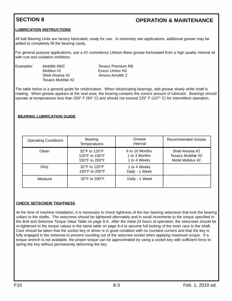
All ball Bearing Units are factory lubricated, ready for use. In extremely wet applications, additional grease may beadded to completely fill the bearing cavity.
For general purpose applications, use a #2 consistency Lithium Base grease formulated from a high quality mineral oilwith rust and oxidation inhibitors.
Examples: Mobilith AW2 Texaco Premium RBMobilux #2 Exxon Unirex N2Shell Alvania #2 Amoco Amolith 2Texaco Multifak #2
The table below is a general guide for relubrication. When relubricating bearings, add grease slowly while shaft isrotating. When grease appears at the seal area, the bearing contains the correct amount of lubricant. Bearings shouldoperate at temperatures less than 200° F (93° C) and should not exceed 225° F (107° C) for intermittent operation.
CHECK SETSCREW TIGHTNESS
At the time of machine installation, it is necessary to check tightness of the two bearing setscrews that lock the bearingcollars to the shafts. The setscrews should be tightened alternately and in small increments to the torque specified inthe Bolt and Setscrew Torque Value Table on page 8-4. After the initial 24 hours of operation, the setscrews should bere-tightened to the torque values in the same table on page 8-4 to assume full locking of the inner race to the shaft.Care should be taken that the socket key or driver is in good condition with no rounded corners and that the key isfully engaged in the setscrew to prevent rounding out of the setscrew socket when applying maximum torque. If atorque wrench is not available, the proper torque can be approximated by using a socket key with sufficient force tospring the key without permanently deforming the key.
Operating Conditions BearingTemperatures
GreaseInterval
Recommended Grease
Shell Alvania #2Texaco Multifak #2Mobil Mobilux #2
6 to 10 Months1 to 3 Months1 to 4 Weeks
1 to 4 WeeksDaily - 1 Week
Daily - 1 Week32°F to 200°FMoisture
32°F to 120°F120°F to 150°F150°F to 200°F
Clean
Dirty 32°F to 120°F150°F to 200°F
BEARING LUBRICATION GUIDE
SECTION 8

F10 8-4 Feb. 1, 2010 ed.
OPERATION & MAINTENANCE
Also at this time, check the tightness of bolts securing pulley and sprocket hubs.
It is a good idea to operate the machine for several hours with all guards and covers in place, but with no productbeing conveyed. This should be done without other noisy machinery turned on. Installation personnel should beclose by to be watchful for malfunctions. Unexplained machine noises, excessive lubricant leakage, beltmistracking, motor overheating and other problems can often be detected and corrected inexpensively beforeputting the unit in service.
BOLT AND SETSCREW TORQUE VALUES
SETSCREWS BOLTS-GENERAL
Wrench Torque
Key Hex Recommended
Across Torque (in-lbs.)
Size Flats Min Max Size Inch-lbs.
No. 10 3/32 28 33
1/4 1/8
5/16 5/32
66 80
3/8-16 240
1/2-13 600
126 156 5/8-11 1200
3/8 3/16 228 275 3/4-10 2100
SECTION 1

F10 9-1 Feb. 1, 2010 ed.
AVC-AIR CLEANOUT OPERATIONFollow the prescribed AVC assembly instructions, referring to the exploded parts drawing for the correct assembly ofplumbing components. The boot shaft should be adjusted so that there is at least one full elevator bucket spacedbelow the inlet opening in the elevator boot. Lengthening the belt may be required to achieve the necessary boot shaftposition. Adjust the AVC cleanout strap so there is approximately one inch of clearance between the strap andbuckets. Ideally, the arc AVC cleanout strap should be positioned onto the bottom of the boot with the belt and bucketassembly lowered to the AVC strap, leaving a minimum of one inch above the AVC strap.
CAUTIONThe AVC can only be installed on the "down leg" elevator side of the boot for it to function properly.Installations of the AVC on the "upleg" elevator side of the boot will cause the boot to not clean out properlyand may cause damage to the elevator.
CAUTIONOver tensioning the elevator belt may cause excessive loads on elevators shafts and bearings, which maycause premature failure of these components.
CAUTIONAdjusting the AVC strap up to an improperly positioned bucket and belt assembly will create a strap arc thatdeflects the airflow direction away from the remaining product, causing cleanout failure. Power requirements:
AIR 95-120 psi ½" diameter air line (minimum)
Electrical 24vdc or 120vac
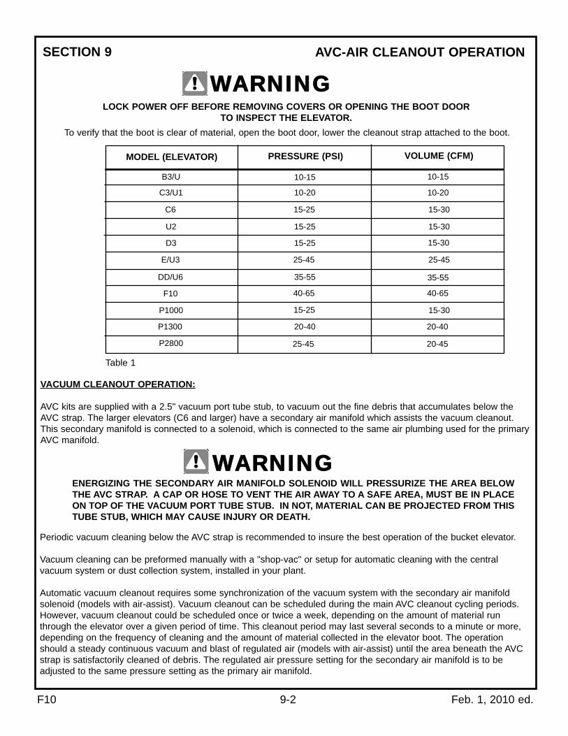
Using the air regulator supplied with the AVC Kit and the solenoids energized, adjust the air pressure according toTable 1. Air pressure and volume depend upon product density, shape and size. Table 1 will provide a guideline fromwhich to determine the appropriate regulator setting for your AVC application.
WARNINGNever make the initial check of the elevator loaded with product. Use eye protection to avoid serious injuryduring assembly and operation on any machinery.
CAUTIONToo much pressure will suspend the remaining product up into the elevator inlet, causing cleanout failure. AIR CYCLING AVC OPERATION:
This operation is preformed after stopping the flow of material into the elevator and the elevator buckets are unable topick up the remains of material left in the boot.
Energize the air solenoid valve and allow the air to sweep the material up toward the elevator inlet where the bucketswill lift the remaining material away to the discharge. We recommend cycling periods of "air on" and "air off", beginningwith a 15 second "air on" period, followed by a 15 second "air off" period. Elevator capacity and discharge heighteffects the on/off cycling duration. Larger capacity elevators will accumulate more material in the boot and may requirea longer "air on" cycle duration. Taller elevators require more time for the last buckets of the "air on" cycle to reach theelevator discharge, adding to the "air off" cycle duration. For example, some applications may require an "air on" cyclefor 15-20 seconds, while the "air off" cycle may be as long as 30 seconds, or more. The number of cycle periods mayalso vary. Three or four cycle periods will usually achieve the desired cleanout effects. Operator experimentation withair pressure and with the "air on" and "air off" cycling periods may be necessary to achieve the desired cleanouteffects.
SECTION 9
F10 9-2 Feb. 1, 2010 ed.
AVC-AIR CLEANOUT OPERATION
LOCK POWER OFF BEFORE REMOVING COVERS OR OPENING THE BOOT DOOR TO INSPECT THE ELEVATOR.
WARNING
To verify that the boot is clear of material, open the boot door, lower the cleanout strap attached to the boot.
MODEL (ELEVATOR) PRESSURE (PSI) VOLUME (CFM)
B3/U
C3/U1
C6
U2
D3
E/U3
DD/U6
F10
P1000
P1300
P2800
10-15
10-20
15-25
15-25
15-25
25-45
35-55
40-65
15-25
20-40
25-45
10-15
10-20
40-65
35-55
15-30
20-45
20-40
15-30
15-30
15-30
25-45
Table 1
VACUUM CLEANOUT OPERATION:
AVC kits are supplied with a 2.5" vacuum port tube stub, to vacuum out the fine debris that accumulates below theAVC strap. The larger elevators (C6 and larger) have a secondary air manifold which assists the vacuum cleanout.This secondary manifold is connected to a solenoid, which is connected to the same air plumbing used for the primaryAVC manifold.
ENERGIZING THE SECONDARY AIR MANIFOLD SOLENOID WILL PRESSURIZE THE AREA BELOWTHE AVC STRAP. A CAP OR HOSE TO VENT THE AIR AWAY TO A SAFE AREA, MUST BE IN PLACEON TOP OF THE VACUUM PORT TUBE STUB. IN NOT, MATERIAL CAN BE PROJECTED FROM THISTUBE STUB, WHICH MAY CAUSE INJURY OR DEATH.
WARNING
Periodic vacuum cleaning below the AVC strap is recommended to insure the best operation of the bucket elevator.
Vacuum cleaning can be preformed manually with a "shop-vac" or setup for automatic cleaning with the centralvacuum system or dust collection system, installed in your plant.
Automatic vacuum cleanout requires some synchronization of the vacuum system with the secondary air manifoldsolenoid (models with air-assist). Vacuum cleanout can be scheduled during the main AVC cleanout cycling periods.However, vacuum cleanout could be scheduled once or twice a week, depending on the amount of material runthrough the elevator over a given period of time. This cleanout period may last several seconds to a minute or more,depending on the frequency of cleaning and the amount of material collected in the elevator boot. The operationshould a steady continuous vacuum and blast of regulated air (models with air-assist) until the area beneath the AVCstrap is satisfactorily cleaned of debris. The regulated air pressure setting for the secondary air manifold is to beadjusted to the same pressure setting as the primary air manifold.
SECTION 9
F10 9-3 Feb. 1, 2010 ed.
AVC-AIR CLEANOUT OPERATION
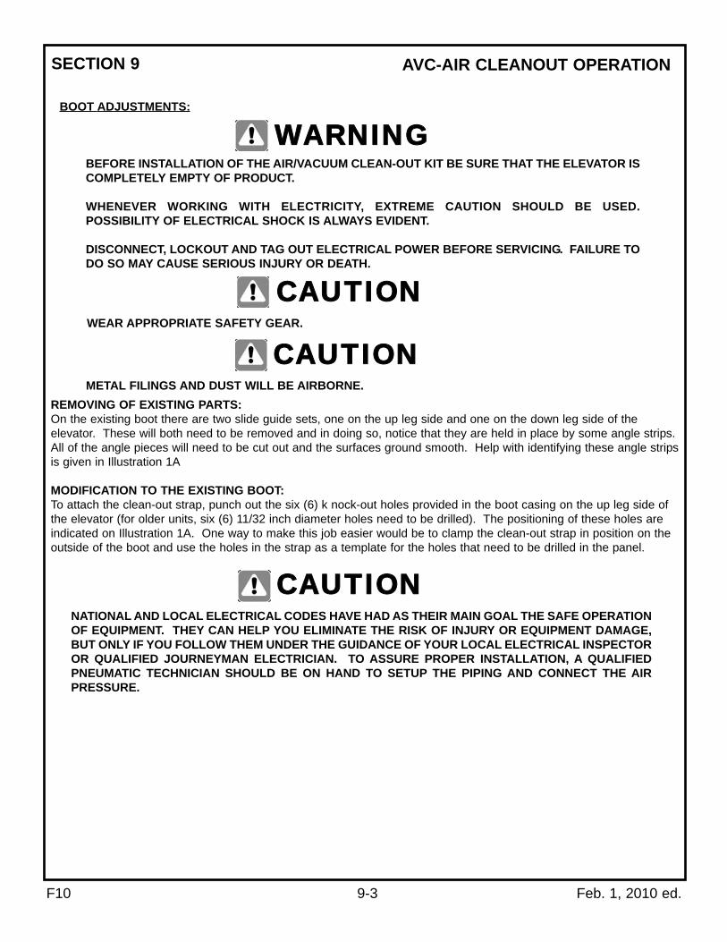
BOOT ADJUSTMENTS:
BEFORE INSTALLATION OF THE AIR/VACUUM CLEAN-OUT KIT BE SURE THAT THE ELEVATOR ISCOMPLETELY EMPTY OF PRODUCT.
WHENEVER WORKING WITH ELECTRICITY, EXTREME CAUTION SHOULD BE USED.POSSIBILITY OF ELECTRICAL SHOCK IS ALWAYS EVIDENT.
DISCONNECT, LOCKOUT AND TAG OUT ELECTRICAL POWER BEFORE SERVICING. FAILURE TODO SO MAY CAUSE SERIOUS INJURY OR DEATH.
WARNING
WEAR APPROPRIATE SAFETY GEAR.
CAUTION
METAL FILINGS AND DUST WILL BE AIRBORNE.
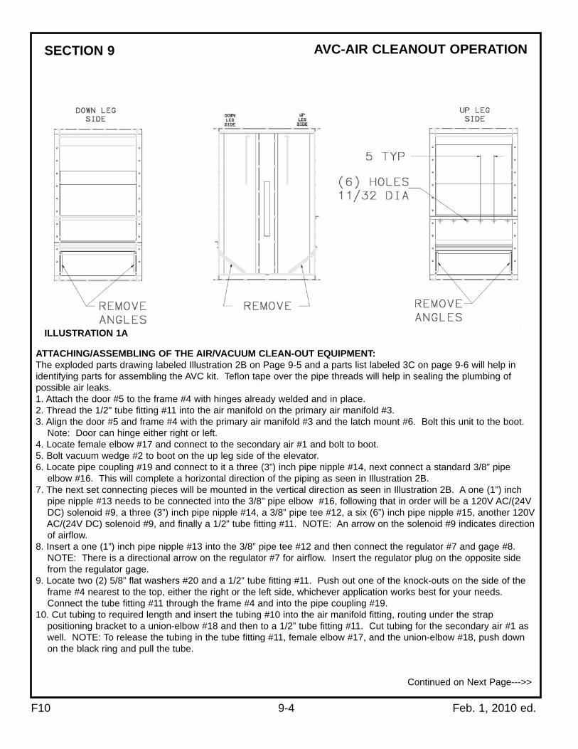
CAUTIONREMOVING OF EXISTING PARTS:On the existing boot there are two slide guide sets, one on the up leg side and one on the down leg side of theelevator. These will both need to be removed and in doing so, notice that they are held in place by some angle strips.All of the angle pieces will need to be cut out and the surfaces ground smooth. Help with identifying these angle stripsis given in Illustration 1A
MODIFICATION TO THE EXISTING BOOT:To attach the clean-out strap, punch out the six (6) k nock-out holes provided in the boot casing on the up leg side ofthe elevator (for older units, six (6) 11/32 inch diameter holes need to be drilled). The positioning of these holes areindicated on Illustration 1A. One way to make this job easier would be to clamp the clean-out strap in position on theoutside of the boot and use the holes in the strap as a template for the holes that need to be drilled in the panel.
NATIONAL AND LOCAL ELECTRICAL CODES HAVE HAD AS THEIR MAIN GOAL THE SAFE OPERATIONOF EQUIPMENT. THEY CAN HELP YOU ELIMINATE THE RISK OF INJURY OR EQUIPMENT DAMAGE,BUT ONLY IF YOU FOLLOW THEM UNDER THE GUIDANCE OF YOUR LOCAL ELECTRICAL INSPECTOROR QUALIFIED JOURNEYMAN ELECTRICIAN. TO ASSURE PROPER INSTALLATION, A QUALIFIEDPNEUMATIC TECHNICIAN SHOULD BE ON HAND TO SETUP THE PIPING AND CONNECT THE AIRPRESSURE.
CAUTION
SECTION 9
F10 9-4 Feb. 1, 2010 ed.
AVC-AIR CLEANOUT OPERATION
ILLUSTRATION 1A
ATTACHING/ASSEMBLING OF THE AIR/VACUUM CLEAN-OUT EQUIPMENT:The exploded parts drawing labeled Illustration 2B on Page 9-5 and a parts list labeled 3C on page 9-6 will help inidentifying parts for assembling the AVC kit. Teflon tape over the pipe threads will help in sealing the plumbing ofpossible air leaks.1. Attach the door #5 to the frame #4 with hinges already welded and in place.2. Thread the 1/2" tube fitting #11 into the air manifold on the primary air manifold #3.3. Align the door #5 and frame #4 with the primary air manifold #3 and the latch mount #6. Bolt this unit to the boot.
Note: Door can hinge either right or left.4. Locate female elbow #17 and connect to the secondary air #1 and bolt to boot. 5. Bolt vacuum wedge #2 to boot on the up leg side of the elevator. 6. Locate pipe coupling #19 and connect to it a three (3”) inch pipe nipple #14, next connect a standard 3/8” pipe
elbow #16. This will complete a horizontal direction of the piping as seen in Illustration 2B.7. The next set connecting pieces will be mounted in the vertical direction as seen in Illustration 2B. A one (1”) inch
pipe nipple #13 needs to be connected into the 3/8” pipe elbow #16, following that in order will be a 120V AC/(24V DC) solenoid #9, a three (3”) inch pipe nipple #14, a 3/8” pipe tee #12, a six (6”) inch pipe nipple #15, another 120V AC/(24V DC) solenoid #9, and finally a 1/2” tube fitting #11. NOTE: An arrow on the solenoid #9 indicates direction of airflow.
8. Insert a one (1”) inch pipe nipple #13 into the 3/8” pipe tee #12 and then connect the regulator #7 and gage #8. NOTE: There is a directional arrow on the regulator #7 for airflow. Insert the regulator plug on the opposite side from the regulator gage.
9. Locate two (2) 5/8” flat washers #20 and a 1/2” tube fitting #11. Push out one of the knock-outs on the side of the frame #4 nearest to the top, either the right or the left side, whichever application works best for your needs. Connect the tube fitting #11 through the frame #4 and into the pipe coupling #19.
10. Cut tubing to required length and insert the tubing #10 into the air manifold fitting, routing under the strap positioning bracket to a union-elbow #18 and then to a 1/2” tube fitting #11. Cut tubing for the secondary air #1 as well. NOTE: To release the tubing in the tube fitting #11, female elbow #17, and the union-elbow #18, push down on the black ring and pull the tube.
Continued on Next Page--->>
SECTION 9

F10 9-5 Feb. 1, 2010 ed.
AVC-AIR CLEANOUT OPERATION
EDGES ARE SHARP. GLOVES SHOULD BE WORN WHEN INSTALLING AND REPOSITIONINGTHE CLEAN-OUT STRAP.
WARNING
11. Bolt the clean-out strap #21 to the boot. NOTE: Removal of the hopper will allow for easy access to attach the strap with 5/16” truss head bolts.
12. Adjust clean-out strap #21 by lifting it up into the buckets, then backing it down by at least one stop on the positioning bracket.
ELECTRICAL SHOCK. A QUALIFIED ELECTRICIAN SHOULD CONNECT WIRING FOR THESOLENOIDS.
WARNING
13. Connect the wires for the solenoids.14. Connect air line hose to the system.
ILLUSTRATION 2B
SECTION 9

F10 9-6 Feb. 1, 2010 ed.
AVC-AIR CLEANOUT OPERATION
INDEX NO. PART NO. DESCRIPTION QTY.
30010 CLEANOUT,AVC,KIT,F10,CS,AC 1
30067 CLEANOUT,AVC,KIT,F10,CS,DC 1
1 43738 WEDGE,ASSEMBLY,SECONDARY AIR,VACUUM ASSIST-MODEL F10 1
2 30055 WEDGE,ASSEMBLY,VACUUM-MODEL F10 1
3 43737 MANIFOLD,ASSEMBLY,PRIMARY AIR MANIFOLD-MODEL F10 1
4 30050 FRAME,ASSEMBLY,DOOR-MODEL F10 1
5 35352 DOOR,ASSEMBLY-MODEL F10 1
6 35333 LATCH,MOUNT,ASSEMBLY-MODEL F10 2
7 35804 REGULATOR W/ GAGE 1
8 GAGE, REGULATOR 1
9.1 35900 SOLENOID,0.375 120V AC (3116.121) 2
9.2 35902 SOLENOID,0.375 24V DC (3116.241) 2
10 35778 TUBING,0.500”OD,SEMI-RIGID,NYLON (2870.50) /FT
11 35776 FITTING,0.500”ODX0.375NPT,STRAIGHT,LEGRIS (2870.30) 3
12 35769 FITTING,TEE,0.375,GALVANIZED (2701.400) 1
13 35770 FITTING,NIPPLE,0.375X1.00,GALVANIZED (2701.310) 2
14 35771 FITTING,NIPPLE,0.375X3.00,GALVANIZED (2701.320) 3
15 35768 FITTING,NIPPLE,0.375X6.00,GALVANIZED (2701.300) 1
16 35772 FITTING,ELBOW,0.375,GALVANIZED (2701.200) 1
17 35775 FITTING,0.500”ODX0.375NPT,FEMALE-ELBOW,LEGRIS (2870.20) 1
18 35774 FITTING,0.500”OD TUBE TO TUBE,UNION-ELBOW,LEGRIS (2870.10) 1
19 35773 FITTING,COUPLING,0.375,GALVANIZED (2701.100) 1
20 30414 WASHER,FLAT,0.625 (2865.1) 2
21 36857 STRAP,ASSY,CLEANOUT-MODEL F10 1
Model F10 AVC Parts List
PARTS LIST 3C
SECTION 9

F10 10-1 Feb. 1, 2010 ed.
PROBLEM DIAGNOSIS
TROUBLE PROBABLE CAUSE
1. Hopper or feed inlet not installed correctly.
Not Operating atRated Capacity
SUGGESTED REMEDY1. Arrange to have material enter boot high
on the up-leg side or low on the down-leg side.
3. Headshaft RPM incorrect. 3. Check capacity table for correct RPM; change sheaves or sprockets as necessary.
2. Arrange feeding method to allow material to drop into the hopper at elevator capacity avoiding overfilling and consequent bridging.
2. Material bridges and will not flow into bucket path fast enough.
4. Buckets caked up. 4. Clean out buckets and if condition persists substitute stainless steel or plastic buckets.
5. Air coming up the spout from the bind forces down legging of light material.
5. Vent the bin or the spout.
Elevator stalls orplugs up.
1. Belt slack not taken out; bucket jam in the boot.
1. Shorten belt; adjust take-up bolts.
2. Not enough power or incorrect heater coils in the starter; motor wired incorrectly.
2. Check power requirements; have competent electrician check circuits & heaters.
3. Elevator discharge or spouting plugged up.
3. Check for foreign material lodged in discharge chute, valves or spouting. Check spouting for bad turns which may hold up flow of material.
4. Bins get overfilled. 4. Install an overflow box, or bin level indicator.
1. Elevator out of plumb. 1. Set elevator straight & plumb. Use steel cables for guying in place of wire, which will stretch & loosen. Arrange elevator braces so they are not forced out of alignment when attached to structures or bins which may shift as they are loaded & unloaded.
3. Loose or deformed buckets 3. Repair or replace buckets.
2. Belt too loose or not centered on pulleys
2. Shorten belt, adjust take-up bolts, shim under head shaft bearings. See Sect. 7.
Noisy operation;buckets rattle in legcasing and boot
SECTION 10

F10 11-1 Feb. 1, 2010 ed.
SPECIFICATIONSF10 BUCKET ELEVATOR
MODEL F10-5000ED F10-7500 F10-1000
Capacity - FreeFlowing Material@110% Water Fill Line
5,000 BPH6,250 ft3/h177 m3/h
7,500 BPH9,375 ft3/h265 m3/h
10,000 BPH12,500 ft3/h354 m3/h
Motor Optional
OptionalDrive Package
Carbon steelConstruction
Boot Pulley
Bootshaft Bearing
Bootshaft
Trunking
Belting
Buckets
16” diameter x 24” wide wing type
Ball bearing take up unit
1 15/16” turned to 1 11/16”
14 gauge twin box columns self supporting
24” wide PVC, rubber optional
11” x7” 14ga or HDPE 2 rows staggered; 22”x7” single row
16 1/2” diameter x 26” wide, vulcanized rubber lagging, QD hub
Ball Bearing Pillow Block, Optional roller
2 15/16” diameter to 100’; 3 7/16” diameter over 100’
12 gauge sides with 7 gauge rim and discharge
Head Pulley
Headshaft RPM
Belt Speed
Short TPH @ 75 lbs. ft3
Short TPH @ 50 lbs. ft3
8”
Headshaft Bearing
Headshaft Diameter
Head Casing
Bucket Spacing 8” 8”
60 RPM 79 RPM 105 RPM
454 FPM341 FPM259 FPM
234 351 468
156 234 312
Up to 12,500ft3/h (354 m3/h) / 10,000 BPH
Boot Casing 7 gauge with angle iron frame
SECTION 11

F10 11-2 Feb. 1, 2010 ed.
DIMENSION DRAWING
F10 BUCKET ELEVATORUp to 12,500 ft3/h (354 m3/h) / 10,000 BPH
SECTION 11

F10 11-3 Feb. 1, 2010 ed.
PARTS DIAGRAMSECTION 11

F10 11-4 Feb. 1, 2010 ed.
PARTS LIST
CS = CARBON STEEL GS = GALVANIZED STEEL DL = DOWN-LEG UL = UP-LEG BRG = BEARING
2BPB = 2 BOLT PILLOW BLOCK CI = CAST IRON ZP = ZINC PLATED TU = TAKE-UP GR = GRADE OD = OUTSIDE
DIAMETER ID = INSIDE DIAMETER 2BFL = 2 BOLT FLANGE BKT = BUCKET HDPE = PLASTIC
VNT = VENTED SS = STAINLESS STEEL EB = ELEVATOR BOLT UHMW = ULTRA HIGH MOLECULAR WEIGHT
HHCS = HEX HEAD CAP SCREW GA = GAUGE BLK = BLACK HD = HEAD DIAMETER PKG = PACKAGE
LEGEND:
INDEX NO. PART NO. DESCRIPTION QTY.F10 ELEVATOR HEAD COMPONENTS (INDEX NUMBERS 1 THROUGH 10)
1 36687 CASING,HEAD,LOWER,F10,CS 12.1 36712 DOOR,ASSY,SIDE,HEAD,F10,LH,CS 12.2 36713 DOOR,ASSY,SIDE,HEAD,F10,RH,CS 13 30459 DEFLECTOR,DT,F10 14 36733 CASING,HEAD,DT,F10,CS 15 36721 CASING,HEAD,UT,F10,CS 16 36728 COVER,INSPECTION,HEAD,F10,CS 17.1 36795 SHAFT,HEAD,F10,#2,2.94=>2.188X48.25,CS AR7.2 36801 SHAFT,HEAD,F10,#2,3.44X51.75,CS AR8.1 35532 PULLEY,DRUM,16.00X26.00X2.937 (WITH JSQD BUSHING) AR8.2 35533 PULLEY,DRUM,16.00X26.00X3.437 (WITH JSQD BUSHING) AR9.1 35065 BRG,2.937,2BPB AR9.2 35069 BRG,3.437,2BPB AR
10.1 36732 SEAL,HEADSHAFT,2.94,F10 AR10.2 41697 SEAL,HEADSHAFT,F10,3.44,UHMW AR15.1 36809 TRUNK,12.00",F10,CS (UP OR DOWN TRUNK, PER PIECE) AR15.2 36808 TRUNK,24.00",F10,CS (UP OR DOWN TRUNK, PER PIECE) AR15.3 36807 TRUNK,36.00",F10,CS (UP OR DOWN TRUNK, PER PIECE) AR15.4 36806 TRUNK,48.00",F10,CS (UP OR DOWN TRUNK, PER PIECE) AR15.5 36805 TRUNK,60.00",F10,CS (UP OR DOWN TRUNK, PER PIECE) AR15.6 36804 TRUNK,72.00",F10,CS (UP OR DOWN TRUNK, PER PIECE) AR15.7 36803 TRUNK,84.00",F10,CS (UP OR DOWN TRUNK, PER PIECE) AR15.8 36802 TRUNK,96.00",F10,CS (UP OR DOWN TRUNK, PER PIECE) AR16 36835 GUSSET,TRUNK,F10,CS AR17 36836 SPREADER,TRUNK,F10,CS (FOR 7' AND 8' TRUNKING ONLY) AR20A 35269 ACCESS,COMPLETE,W/COVER,F10,CS 120 36780 CASING,ACCESS,ASSY,F10,CS 121 36777 COVER,ACCESS,BACK,F10,CS 122 36778 COVER,ASSY,ACCESS,FRONT,F10,CS 123 36286 SLIDE,INSPECTION,ACCESS,CS 224 30466 CAP,TAPERED,INST.TUBE 225 41947 MANUAL,SERVICE,F10 1
F10 ELEVATOR BOOT COMPONENTS (INDEX NUMBERS 30 THROUGH 44 & 47)30 36739 CASING,BOOT,ASSY,F10,CS 131 35538 PULLEY,WING,16.00X24.00CF 132 36764 SHAFT,BOOT,1.94=>1.69X35.50,F10,CS 133 35717 COVER,SLOT,UHMW,F10 134 35619 BOLT,HH-TAP,ACME,1.00-5X19.00,ZP (WITH WELDED HEX NUT) 235 30675 NUT,HEX,ACME,JAM,1.00-5,ZP 236 34427 NUT,ASSY,TU,BOLT,E/DD/F10,CS 237 35049 BRG,1.687,TAKEUP 238 34420 BRKT,BOLT,ASSY,E/DD/F10,CS 239 36759 ANGLE,BEARING,BOOT,F10,CS 440 36761 COVER,BOOT,DL,F10,CS 144 36762 SLIDE,ASSY,BOOT,F10,CS 245 35407 HOPPER,SPOUT,KIT,F10,CS 147 36760 RAIL,BEARING,BOOT,F10,CS 450 -------- (SEE ELEVATOR BELT IN ELEVATOR ACCESSORIES SECTION OR CONSULT FACTORY) AR51 36450 CLAMP,BELT,KIT,F10,CS 152.1 30439 BKT,HDPE,11.00X7.00,WHITE AR52.2 35756 BKT,CS,11.00X7.00,14GA,CC AR52.3 35755 BKT,CS,11.00X7.00,14GA,VNT AR52.4 30436 BKT,22X7,CC,TYPE-B,REG-STEEL LESS BRACE AR52.5 35758 BKT,22X7,CC,TYPE-B,REG-STEEL W/BRACE AR52.6 30437 BKT,22X7,CC,TYPE-B,REG-STEEL,VNT LESS BRACE AR52.7 35757 BKT,22X7,CC,TYPE-B,REG-STEEL,VNT W/BRACE AR53.1 30494 CUSHION,BUCKET,BLK,F10,0.125X4.00X11.00 AR53.2 30496 CUSHION,BUCKET,BLK,F10,0.125X4.00X22.00 AR54 51359 BOLT,EB,0.312-18X1.50,#3 AR55 30152 NUT,HEX,0.312-18,ZP AR60&61 39816 SWITCH,DISCONNECT&SHUTOFF (ELEVATOR SAFETY SWITCH PKG) 1
30581 SCREW,HHCS,0.375-16X1.00,ZP AR30153 NUT,HEX,0.375-16,ZP AR
SECTION 11

349983497434975
BELT,24”,UNI-PLY,250,BLK,180F (1 ROW)BELT,24”,UNI-FORM R,BLK,212F (2 ROWS)BELT,24”,UNI-FORM R,BLK,212F (1 ROW)
34999 BELT,24”,UNI-PLY,250,BLK,180F (2 ROWS)
QUANTITY
BUCKETS
PART NO. DESCRIPTION
AR
ARAR
AR
ARAR
AR
PER FOOT
PER FOOT
PER FOOT
PER FOOT
FOR ADDITIONAL BUCKET OPTIONS AND SPECIFICATIONS, SEE UNIVERSAL ELEVATOR BUCKETS IN ELEVATOR ACCESSORIES SECTION
FOR ADDITIONAL BELT OPTIONS AND SPECIFICATIONS, SEE ELEVATOR BELT IN ELEVATOR ACCESSORIES SECTION
BELT
PART NO. DESCRIPTION QUANTITY
F10 11-5 Feb. 1, 2010 ed.
PARTS LIST
MODEL F10 - BELT -BUCKETS - BOLTS - CUSHIONS - WASHERS
NOTE: If the added extension will place your elevator in a belt category requiring stronger belt, the entire belt should be replaced. As speed isincreased or buckets are added check the drive requirements.
BELT LENGTH FORMULA: 2 x DH +7'6” BUCKET FORMULA: 6 X DH +20 (2 ROWS); 3 X DH+10 (1 ROW) TRUNKING FORMULA: DH MINUS 10'
BLK = BLACK F = FAHRENHEIT WHT = WHITE BKT = BUCKET CS = CARBON STEELSS = STAINLESS STEEL GA = GAUGE VNT = VENTED EB = ELEVATOR BOLT HD = HEAD DIAMETER
LEGEND:
PRICE EACH
BOLTS - CUSHIONS - WASHERS
PART NO.5135930152
30496
30494
31723
BOLT,EB,0.312-18X1.50,#3NUT,HEXFLANE,0.312-18,ZPCUSHION,BUCKET,BLK,F10,0.125X4.00X11.00 (11”X7” BKT)
WASHER,BKT-SPACER,1.00ODX0.344IDX0.500THK,HDPECUSHION,BUCKET,BLK,F10,0.125X4.00X22.00 (22”X7” BKT)
DESCRIPTION
FOR ADDITIONAL OPTIONS AND SPECIFICATIONS, PLEASE CONTACT THE FACTORY
AR
ARAR
ARAR
3043935756
304363575730437
BKT,HDPE,11.00X7.00,WHITEBKT,CS,11.00X7.00,14GA,CC
BKT,22X7,CC,TYPE-B,REG-STEEL,VNT,W/BRACEBKT,22X7,CC,TYPE-B,REG-STEEL,VNT,LESS BRACE
BKT,22X7,CC,TYPE-B,REG-STEEL,LESS BRACE
3575535758
BKT,CS,11.00X7.00,14GA,CC,VNTBKT,22X7,CC,TYPE-B,REG-STEEL,W/BRACE
SECTION 11

43516435174351843519
SWITCH,M800,UNDERSPEED,110VAC,50/60HZSWITCH,M800,UNDERSPEED,24VDCSWITCH,M800,UNDERSPEED,220VAC,50/60HZWHIRLIGIG,SENSOR,MOUNT,WG1-4B
DESCRIPTIONPART NO.SENSOR ACCESSORIES
F10 11-6 Feb. 1, 2010 ed.
OPTIONAL EQUIPMENT
CS = CARBON STEEL GS = GALVANIZED STEEL ABC = AUTOMATIC BOOT CLEANOUT HDC = HINGED DOOR CLEANOUTAVC = AIR VACUUM CLEANOUT AC = ALTERNATE CURRENT DC = DIRECT CURRENT VAC = VOLT ATERNATE CURRENTVDC = VOLT DIRECT CURRENT HZ = HERTZ
LEGEND:
PART NO.3540735408
DESCRIPTIONHOPPER,SPOUT,KIT,F10,CSHOPPER,DUMP,KIT,F10,CS
INTAKE ACCESSORIES
36851 COVER,HOPPER,DUMP,F10,GS36850 COVER,HOPPER,SPOUT,F10,CS
ADAPTOR,SQUARE2ROUND,16"X14",CSADAPTOR,SQUARE2ROUND,16"X16",CS
4253033134
ADAPTOR,VALVE,ASSY,E/U3,CS
392273919639213
32937
VALVE,ASSY,16",3WAY,MANUAL,CS (VALVE BODY ONLY)VALVE,ASSY,16",2WAY,MANUAL,CS (VALVE BODY ONLY)VALVE,ASSY,16",OFFSET,MANUAL,CS (VALVE BODY ONLY)
DESCRIPTIONPART NO.DISCHARGE ACCESSORIES
FOR USE WITH VALVES:1) NEEDED: (1) (32937) ADAPTOR,VALVE TO GET DISCHARGE STRAIGHT DOWN2) IF ROUND OUTLETS ARE DESIRED, ADD ON CORRECT NUMBER OF DESIRED SQUARE TO ROUND OUTLETS
NOTE: For more discharge options see Miscellaneous Accessories under Elevator Accessories in the catalog.
35409392743001030067
CLEANOUT,ABC,KIT,F10,CSCLEANOUT,HDC,KIT,F10,CSCLEANOUT,AVC,KIT,F10,CS,ACCLEANOUT,AVC,KIT,F10,CS,DC
DESCRIPTIONPART NO.CLEANOUT ACCESSORIES
PLATFORM,SERVICE,F10,CS35412354113541332514
35695
PART NO.
PLATFORM,CONSIGNOR,F10,CSRESTPLATFORM,F10,CSCAGE,FLARED,SAFETY,KIT (3' FLARED ENTRY)SERVICE LADDER, PER FOOT DH MINUS 10'SAFETY CAGE, PER FOOT
WEATHER & DUST SEALING, BASE PRICE (LEGGING ONLY)- ADD PER FOOT OF DISCHARGE HEIGHT
ADHESIVE,DOC-700-INDUSTRIAL-GR,S-CLEAR,10.3-OZ (PER TUBE)VENT OPENING IN HEAD (TO RECEIVE 4” OR 6" PIPE)
SERVICE ACCESSORIESDESCRIPTION
SECTION 11

#2 DRIVE PARTS LIST
INDEX NO. PART NO. DESCRIPTION QTY.1 36944 MOUNT,ASSY,MOTOR,F10,RH,CS 12 36937 RAIL,ASSY,MOTORMOUNT,F10,CS 2
3&4 39816 SWITCH,DISCONNECT&SHUTOFF (ELEVATOR SAFETY SWITCH PKG) 15 36950 BRACE,MOTORMOUNT,F10,CS 16 36951 SLEEVE,ASSY,DRIVEGUARD,F10,RH,CS 17 36955 BRKT,ASSY,DRIVEGUARD,F10,RH,CS 1
8.1 36960 GUARD,DRIVE,F10,#2,SMALL,CS,LOWER AR8.2 36970 GUARD,DRIVE,F10,#2,MEDIUM,CS,LOWER AR8.3 36983 GUARD,DRIVE,F10,#2,LARGE,CS,LOWER AR9.1 36959 GUARD,DRIVE,F10,#2,SMALL,CS,UPPER AR9.2 36969 GUARD,DRIVE,F10,#2,MEDIUM,CS,UPPER AR9.3 36982 GUARD,DRIVE,F10,#2,LARGE,CS,UPPER AR
F10 11-7 Feb. 1, 2010 ed.
SECTION 11
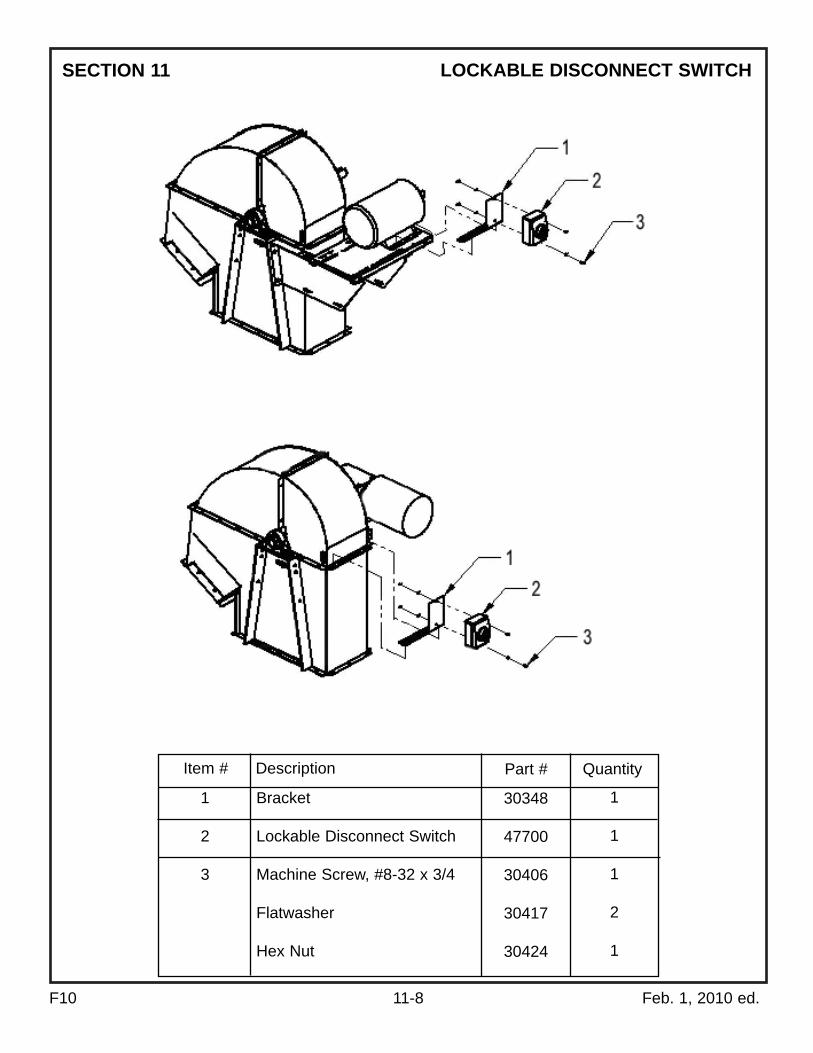
F10 11-8 Feb. 1, 2010 ed.
LOCKABLE DISCONNECT SWITCH
Item # Description Quantity
1
2
3
Bracket
Lockable Disconnect Switch
Machine Screw, #8-32 x 3/4
Flatwasher
Hex Nut
Part #
30348
47700
30406
30417
30424
1
1
1
2
1
SECTION 11

F10 11-9 Feb. 1, 2010 ed.
SERVICE PLATFORMSECTION 11
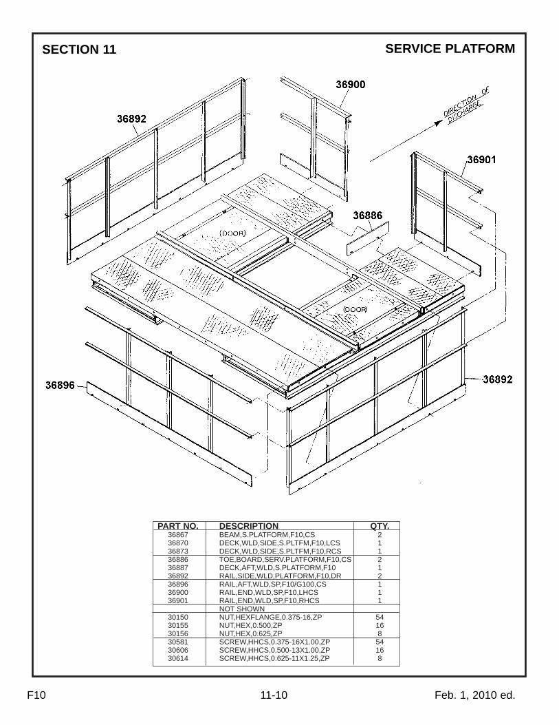
PART NO. DESCRIPTION QTY.36867 BEAM,S.PLATFORM,F10,CS 236870 DECK,WLD,SIDE,S.PLTFM,F10,LCS 136873 DECK,WLD,SIDE,S.PLTFM,F10,RCS 136886 TOE,BOARD,SERV.PLATFORM,F10,CS 236887 DECK,AFT,WLD,S.PLATFORM,F10 136892 RAIL,SIDE,WLD,PLATFORM,F10,DR 236896 RAIL,AFT,WLD,SP,F10/G100,CS 136900 RAIL,END,WLD,SP,F10,LHCS 136901 RAIL,END,WLD,SP,F10,RHCS 1
NOT SHOWN30150 NUT,HEXFLANGE,0.375-16,ZP 5430155 NUT,HEX,0.500,ZP 1630156 NUT,HEX,0.625,ZP 830581 SCREW,HHCS,0.375-16X1.00,ZP 5430606 SCREW,HHCS,0.500-13X1.00,ZP 1630614 SCREW,HHCS,0.625-11X1.25,ZP 8
SERVICE PLATFORM
F10 11-10 Feb. 1, 2010 ed.
SECTION 11

PART NO. DESCRIPTION QTY.36911 DECK,WLD,SIDE,C.PLATFM,F10,RCS 136912 DECK,WLD,SIDE,C.PLATFM,F10,LCS 136920 DECK,WLD,FRONT,C.PLATFORM,F10 136892 RAIL,SIDE,WLD,PLATFORM,F10,DR 236867 BEAM,S.PLATFORM,F10,CS 136922 BEAM,UL,C.PLATFORM,WLD,F10,CS 136896 RAIL,AFT,WLD,SP,F10/G100,CS 236924 BOLT,0.50X16.00,CP,F10,CS 236887 DECK,AFT,WLD,S.PLATFORM,F10 1
NOT SHOWN30153 NUT,HEX,0.375-16,ZP 5030155 NUT,HEX,0.500,ZP 1830156 NUT,HEX,0.625,ZP 830581 SCREW,HHCS,0.375-16X1.00,ZP 5030606 SCREW,HHCS,0.500-13X1.00,ZP 1630614 SCREWMGGCS,0.625-11X1.25,ZP 8
CONSIGNOR PLATFORM
F10 11-11 Feb. 1, 2010 ed.
SECTION 11

PART NO. DESCRIPTION QTY.30421 RAIL,END,RESTPLATFORM 431575 BRACE,PLATFORMS 230422 TOE,BOARD,BACK,RESTPLATFORM 131574 BRACE,RESTPLATFORM 131576 RAIL,WLD,RESTPLATFORM 236931 BRKT,DECKFRAME,F10,CS 1
NOT SHOWN36935 GUSSET,WLD,REST,PLTFRM,F10,RCS 136934 GUSSET,WLD,REST,PLTRM,F10,LCS 133566 BOLT,0.50X13.75,RP,FD3,CS 230661 NUT,HEXLOCK,REVERSE,0.50-13,ZP 430580 SCREW,HHCS,0.375-16X0.75,ZP 2630150 NUT,HEXFLANGE,0.375-16,ZP 26
REST PLATFORM
F10 11-12 Feb. 1, 2010 ed.
SECTION 11
36931

REST PLATFORM
F10 11-13 Feb. 1, 2010 ed.
SECTION 11

F10 11-14 Feb. 1, 2010 ed.
DECAL DIAGRAMSECTION 11

F10 11-15 Feb. 1, 2010 ed.
DECAL PARTS LIST
DRAWING PART SYMBOL NUMBER DESCRIPTION QTY.
A 30139 Decal,Safety Instruction 1B 30137 Decal,Hopper Warning Sign 2C 30140 Decal,Danger Sign 1D 30141 Decal,Adjustable Clutch Sign 0E 30128 Decal,Pinch Point Sign 1F 41809 Decal,Safety,Instruction,Conv 0G 30132 Decal,Auto Start Warning 0H 30131 Decal,Disconnect/Lockout Sign 1J 30143 Decal,Crossover 0K 30129 Decal,Access&CVR Warning Sign 2L 30144 Decal,Hopper Cover Warning Sign 1M 30133 Decal,Vertical Universal Sign 2N 30145 Decal,Horizontal,3.00X14.50 (Universal) 0P 30134 Decal,Installation Maintenance (Manual Holder Sign) 1R 30135 Decal,Identification Sign 1S 30146 Decal,Drive Guard Warning 1T 30130 Decal, Please Check Setscrew 2
SECTION 11

F10 12-1 Feb. 1, 2010 ed.
The Company expects the customer/owner of supplied equipment to comply with all applicable safetycode standards, and good practices. Below is a list of organizations that publish various standards thatmay apply to your machine. This list is included for your convenience, does not necessarily contain allcodes and standards, and is to be periodically updated by you.
Universal recommends that owners and operators make an effort to keep themselves informed on thetopic of safety. Standards are constantly evolving and it requires vigilance to remain fully informed.
Here is a list of some of the various standards that are categorized by subject of concern:
SOURCES OF STANDARDS AND CODES
Altering Safety CharacteristicsBackstops, BrakesCages (for ladders)Drive GuardsElectricalEmergency Stop SwitchesLaddersLock Out Hazardous Energy SourcesPlatformsPoint of Operation
Guards and CoversShafting, shaft ends, couplings, guardsInlet GratesInterfacing Machines
ANSI B20.1 paragraph 5-12.7ANSI B20.1 paragraph 5.05OSHA 1910.24d, 2, 5OSHA 1910.219m; 217c2bNEC; OSHA 1910.300ANSI B20.1 paragraph 5-11.2cOSHA 1910.24bOSHA 1910.147OSHA 1910.23c3; 23e; 24bOSHA 1910.212a3; 217c2b; ANSI B20.1paragraph 5.09.1.1
OSHA 1910.219; .219c4; .219IOSHA 1910.272jANSI B20.1 paragraph 5-11c
Safety Concern Organization and Publication Section
For additional copies: write Universal Industries, Inc. PO Box 308 Cedar Falls, IA 50613
American Society of Agricultural Engineers (ASAE)2950 Niles RoadSt. Joseph, MI 10018
American National Standards Institute (ANSI)25 West 43rd Street, 4th FloorNew York, NY 10036Phone: (212) 642-4900
National Fire Protection Association (NFPA)(Publisher of the National Electrical Code)(NEC)P.O. Box 9101Quincy, Massachusetts 02269-9101Phone: (800) 344-3555
American Society of Mechanical Engineers (ASME)345 East 47th StreetNew York, NY 10017
U.S. Department of Agriculture (USDA)14th Street and Independence Avenue, S.W.Washington, DC 20250
Factory Mutual Engr. Corp. (FM)P. O. Box 9102Norwood, MA 02062Phone: (781) 440-8000
Society of Automotive Engineers (SAE)400 Commonwealth DriveWarrenberg, PA 15096
Underwriters Laboratories (UL)207 East Ohio StreetChicago, IL 60611
American Society for Testing and Materials (ASTM)100 Barr Harbor DriveWest Conshohocken, PA 19428-2959 Phone: (610) 832-9585
OSHA, Office of Mechanical Engineering Safety Standards, Room N3621 OSHA Dept. of Labor200 Constitution N.W.Washington, DC 20210
Addresses of some of the various societies publishing rules, regulations and recommended practices:
SECTION 12

F10 13-1 Feb. 1, 2010 ed.
PERSONNEL CHECK FORM
RECORD OF PERSONS WHO HAVE READ AND UNDERSTOOD THIS MANUAL
The owner or employer responsible for the safe operation of this machine shall instruct allpersons operating or maintaining this machine how to do so in a safe manner. This should alsoinclude good housekeeping practices.
Have the person(s) read this manual and sign in the place provided below, indicating thatthey understand the safety messages in the manual.
If there is some barrier to their successful reading of this manual, the manual should be read tothe person(s) and questions asked to check their understanding. Have them sign below afterdemonstrating their understanding of the safety messages in the manual.
I have read and understood the safety messages in this manual
The employer should retain this sheet as a permanent record.
Copies of this page or of the manual can be obtained from:
Universal Industries, Inc. PO Box 308 Cedar Falls, IA 50613 Phone: (319) 277-7501 Fax: (319) 277-2318
Name NameDate Date
SECTION 13

E 14-1 Feb. 1, 2010 ed.
Air Cleanout Operation ....................................................................................................................9-1AVC-Air Cleanout Operation............................................................................................................9-1AVC Assembly .................................................................................................................................9-4AVC Parts Diagram..........................................................................................................................9-5AVC Parts List..................................................................................................................................9-6Backstops ........................................................................................................................................8-2Bar Clamp........................................................................................................................................8-2Bearing Lubrication..........................................................................................................................8-2Belt, Buckets, Etc. ..........................................................................................................................11-5Belt Splice & Bucket Installation ......................................................................................................7-1Bolt & Set Torque Values .................................................................................................................8-4Boot Adjustments .............................................................................................................................9-3Bucket Spacing ................................................................................................................................7-1Consignor Platform.......................................................................................................................11-11Decals, Parts List .........................................................................................................................11-15Dimension Drawing ........................................................................................................................11-2Disclaimer for Misuse .....................................................................................................................3-1Electrical Shock Hazards.................................................................................................................5-1Elevator Installation..........................................................................................................................6-1Emergency Shut-Off Switches.........................................................................................................6-3General Installation ..........................................................................................................................4-1General Operation ...........................................................................................................................8-1General Safety Practices .................................................................................................................2-2General Specifications ...................................................................................................................11-1Installations - Electrical ....................................................................................................................5-1Installations - General ......................................................................................................................4-1Installer Checklist.............................................................................................................................6-2Lockable Disconnect Switch ........................................................................................................11-12Lubrication Instructions....................................................................................................................8-3Maintenance ....................................................................................................................................8-1Mistracking.......................................................................................................................................7-2Motor Rotation Check ......................................................................................................................4-1Open System Elevators ...................................................................................................................2-2Operation & Maintenance ................................................................................................................8-1Operator Injury .................................................................................................................................5-1Optional Equipment........................................................................................................................11-6Parts Diagram, F10........................................................................................................................11-3Parts Diagram, Decals .................................................................................................................11-14Parts Diagram, AVC.........................................................................................................................9-5Parts Diagram, Lockable Disconnect Switch .................................................................................11-8Parts Diagram & List, Consignor Platform ...................................................................................11-11Parts Diagram & List, Rest Platform ............................................................................................11-12Parts Diagram & List, Service Platform..........................................................................................11-9Parts List, AVC.................................................................................................................................9-6Parts List, F10 ................................................................................................................................11-4Parts List, Decals .........................................................................................................................11-15Parts List, #2 Drive.........................................................................................................................11-7Periodic Inspections.........................................................................................................................8-1Personnel Check Off Form ............................................................................................................13-1Problem Diagnosis.........................................................................................................................10-1Product Safety Statement ................................................................................................................2-1Protection From Short Circuits.........................................................................................................5-1Receiving .........................................................................................................................................3-1Rest Platform ...............................................................................................................................11-12

F10 14-2 Feb. 1, 2010 ed.
Safety...............................................................................................................................................2-1Safety Alert Symbols........................................................................................................................2-1Service Platform.............................................................................................................................11-9Setscrew Tightness..........................................................................................................................8-4Slight Current Excesses ..................................................................................................................5-1Sources of Standards & Codes .....................................................................................................12-1Specifications .................................................................................................................................11-1Start-Up & Empty Run-In Period......................................................................................................7-2Terms and Conditions of Sale..........................................................................................................1-1Troubleshooting .............................................................................................................................10-1Universal Machine Identification ........................................................................................Front CoverVacuum Cleaning Operation............................................................................................................9-2Walkway Construction Over Machine..............................................................................................2-3