
Cover XGT Cnet - ayperelektrik.com.tr · Contents Chapter 1 Overview ----- 1-1 ~ 1-1 1.1...
144
Read this manual carefully before installing, wiring, operating, servicing or inspecting this equipment. Keep this manual within easy reach for quick reference. LS Programmable Logic Controller XGT Cnet I/F Module XGL-C22A/XGL-C42A/XGL-CH2A
Transcript of Cover XGT Cnet - ayperelektrik.com.tr · Contents Chapter 1 Overview ----- 1-1 ~ 1-1 1.1...

Read this manual carefully before installing, wiring, operating, servicing or inspecting this equipment.
Keep this manual within easy reach for quick reference.
LS Programmable Logic Controller
XGT Cnet I/F Module XGL-C22A/XGL-C42A/XGL-CH2A

Safety Instructions
Before using the product … For your safety and effective operation, please read the safety instructions thoroughly before using the product. ► Safety Instructions should always be observed in order to prevent accident
or risk with the safe and proper use the product. ► Instructions are separated into “Warning” and “Caution”, and the meaning of
the terms is as follows;
This symbol indicates the possibility of serious injury or death if some applicable instruction is violated
This symbol indicates the possibility of slight injury or damage to products if some applicable instruction is violated
► The marks displayed on the product and in the user’s manual have the
following meanings.
Be careful! Danger may be expected.
Be careful! Electric shock may occur. ► The user’s manual even after read shall be kept available and accessible to
any user of the product.
Warning
Caution

Safety Instructions
Safety Instructions when designing
Please, install protection circuit on the exterior of PLC to protect the whole control system from any error in external power or PLC
module. Any abnormal output or operation may cause serious problem in safety of the whole system.
- Install applicable protection unit on the exterior of PLC to protect the system from physical damage such as emergent stop switch, protection circuit, the upper/lowest limit switch, forward/reverse operation interlock circuit, etc.
- If any system error (watch-dog timer error, module installation error, etc.) is detected during CPU operation in PLC, the whole output is designed to be turned off and stopped for system safety. However, in case CPU error if caused on output device itself such as relay or TR can not be detected, the output may be kept on, which may cause serious problems. Thus, you are recommended to install an addition circuit to monitor the output status.
Never connect the overload than rated to the output module nor allow the output circuit to have a short circuit, which may cause a fire.
Never let the external power of the output circuit be designed to be On earlier than PLC power, which may cause abnormal output or
operation.
In case of data exchange between computer or other external equipment and PLC through communication or any operation of PLC (e.g. operation mode change), please install interlock in the sequence program to protect the system from any error. If not, it may cause abnormal output or operation.
Warning

Safety Instructions
Safety Instructions when designing
Safety Instructions when designing
I/O signal or communication line shall be wired at least 100mm away from a high-voltage cable or power line. If not, it may cause abnormal output or operation.
Caution
Use PLC only in the environment specified in PLC manual or general standard of data sheet. If not, electric shock, fire, abnormal operation of the product or flames may be caused.
Before installing the module, be sure PLC power is off. If not, electric shock or damage on the product may be caused.
Be sure that each module of PLC is correctly secured. If the product is installed loosely or incorrectly, abnormal operation, error or dropping may be caused.
Be sure that I/O or extension connecter is correctly secured. If not, electric shock, fire or abnormal operation may be caused.
If lots of vibration is expected in the installation environment, don’t let PLC directly vibrated. Electric shock, fire or abnormal operation may be caused.
Don’t let any metallic foreign materials inside the product, which may cause electric shock, fire or abnormal operation..
Caution

Safety Instructions
Safety Instructions when wiring
Prior to wiring, be sure that power of PLC and external power is turned off. If not, electric shock or damage on the product may be caused.
Before PLC system is powered on, be sure that all the covers of the terminal are securely closed. If not, electric shock may be caused
Warning
Let the wiring installed correctly after checking the voltage rated of each product and the arrangement of terminals. If not, fire, electric shock or abnormal operation may be caused.
Secure the screws of terminals tightly with specified torque when wiring. If the screws of terminals get loose, short circuit, fire or abnormal operation may be caused.
* Surely use the ground wire of Class 3 for FG terminals, which is exclusively used for PLC. If the terminals not grounded correctly, abnormal operation may be caused.
Don’t let any foreign materials such as wiring waste inside the module while wiring, which may cause fire, damage on the product or abnormal operation.
Caution

Safety Instructions
Safety Instructions for test-operation or repair
Safety Instructions for waste disposal
Don’t touch the terminal when powered. Electric shock or abnormal operation may occur.
Prior to cleaning or tightening the terminal screws, let all the external power off including PLC power. If not, electric shock or abnormal operation may occur.
Don’t let the battery recharged, disassembled, heated, short or soldered. Heat, explosion or ignition may cause injuries or fire.
Warning
Don’t remove PCB from the module case nor remodel the module. Fire, electric shock or abnormal operation may occur.
Prior to installing or disassembling the module, let all the external power off including PLC power. If not, electric shock or abnormal operation may occur.
Keep any wireless installations or cell phone at least 30cm away from PLC. If not, abnormal operation may be caused.
Caution
Product or battery waste shall be processed as industrial waste. The waste may discharge toxic materials or explode itself.
Caution

Revision History
Version Date Remark Page
V 1.0 ’06.02 First Edition -

◎ Contents ◎
Chapter 1 Overview ------------------------------------------------------------------------------------------- 1-1 ~ 1-1
1.1 Introduction ----------------------------------------------------------------------------------------------------- 1-1
1.2 Characteristics ------------------------------------------------------------------------------------------------- 1-1
Chapter 2 Product Specifications ------------------------------------------------------------------------ 2-1 ~ 2-5
2.1 General Specifications --------------------------------------------------------------------------------------- 2-1
2.2 Performance Specifications --------------------------------------------------------------------------------- 2-2 2.3 Designations of Parts ----------------------------------------------------------------------------------------- 2-3 2.4 Cable Specifications ------------------------------------------------------------------------------------------- 2-4 2.5 Terminal Resistance ------------------------------------------------------------------------------------------- 2-5
Chapter 3 Performance Specifications ----------------------------------------------------------------- 3-1 ~ 3-5
3.1 Operation Mode Setting ------------------------------------------------------------------------------------- 3-1 3.2 Channel Operation during Normal Run ----------------------------------------------------------------- 3-2 3.3 Channel Operation in Diagnosis Mode (Loop-Back) ------------------------------------------------- 3-3 3.4 Method of Serial Interface ----------------------------------------------------------------------------------- 3-3
3.4.1 RS-232C Interface ---------------------------------------------------------------------------------- 3-3 3.4.2 RS-422 Interface ------------------------------------------------------------------------------------ 3-5
Chapter 4 Installation and Test Operation ------------------------------------------------------------- 4-1 ~ 4-2
4.1 Installation Environment ------------------------------------------------------------------------------------- 4-1 4.2 Precautions for Handling ------------------------------------------------------------------------------------ 4-1 4.3 Operation Sequence ------------------------------------------------------------------------------------------4-2
Chapter 5 System Configuration ---------------------------------------------------------------------------5-1~ 5-8
5.1 Available System Configurations--------------------------------------------------------------------------- 5-1
5.1.1 1:1 connection (no modem) to PC (HMI) ------------------------------------------------------ 5-1 5.1.2 1:1 dedicated modem connection to PC (HMI) ----------------------------------------------- 5-1 5.1.3 Modem connection to PC & Communication between Cnet I/F modules ------------- 5-2

5.1.4 Dedicated communication with PC(HMI) & Other company’s RS-422 communication ------------------------------------------------------------------------------------------------------------ 5-3 5.1.5 Optical modem communication for mobile communication ------------------------------- 5-4 5.1.6 Wireless modem communication for communication between revolution bodies ------------------------------------------------------------------------------------------------------------ 5-5 5.1.7 TM/TC communication system ------------------------------------------------------------------- 5-6
5.2 Unavailable System Configurations----------------------------------------------------------------------- 5-7 5.2.1 Dial-up modem communication between Cnet I/F modules ------------------------------ 5-7 5.2.2 XG5000 connection using RS-422 channel of Cnet I/F module ------------------------- 5-8
Chapter 6 Basic Communication Parameters Setting---------------------------------------------- 6-1 ~ 6-8
6.1 Communication Module Registration ----------------------------------------------------------------- 6-1 6.2 Transmission Specification Settings ------------------------------------------------------------------ 6-4
6.2.1 Setting items ------------------------------------------------------------------------------------------ 6-4 6.2.2 Setting method---------------------------------------------------------------------------------------- 6-6
Chapter 7 Communication Functions ----------------------------------------------------------------- 7-1 ~ 7-33
7.1 Exclusive Service ---------------------------------------------------------------------------------------------- 7-1
7.1.1 Introduction -------------------------------------------------------------------------------------------- 7-1 7.1.2 XGT Server -------------------------------------------------------------------------------------------- 7-2 7.1.3 Modbus Server --------------------------------------------------------------------------------------- 7-2
7.2 P2P service ----------------------------------------------------------------------------------------------------- 7-4 7.2.1 Introduction -------------------------------------------------------------------------------------------- 7-4 7.2.2 Configuration of P2P Parameters --------------------------------------------------------------- 7-5 7.2.3 Channel Information -------------------------------------------------------------------------------- 7-5 7.2.4 Block Information ------------------------------------------------------------------------------------ 7-8 7.2.5 User Defined Frame Information---------------------------------------------------------------- 7-15 7.2.6 P2P Service Operation --------------------------------------------------------------------------- 7-24
7.3 Remote Connection ----------------------------------------------------------------------------------------- 7-26 7.3.1 Introduction ------------------------------------------------------------------------------------------ 7-26 7.3.2 XG5000 Remote Connection ------------------------------------------------------------------- 7-26 7.3.3 Remote Connection between Cnet I/F modules ------------------------------------------- 7-31
Chapter 8 XGT Dedicated Communication Function -------------------------------------------- 8-1 ~ 8-15
8.1 Dedicated Protocol Communication ---------------------------------------------------------------------- 8-1
8.1.1 Introduction ------------------------------------------------------------------------------------------- 8-1 8.1.2 Frame Structure -------------------------------------------------------------------------------------- 8-2 8.1.3 Commands List ----------------------------------------------------------------------------------- 8-3 8.1.4 Command Details ----------------------------------------------------------------------------------- 8-4

Chapter 9 Program Examples---------------------------------------------------------------------------- 9-1 ~ 9-31
9.1 Program Examples------------------------------------------------------------------------------------------- 9-1
9.1.1 Example of dedicated service -------------------------------------------------------------------- 9-1 9.2 P2P service ----------------------------------------------------------------------------------------------------- 9-5
9.2.1 XGT Client --------------------------------------------------------------------------------------------- 9-5 9.2.2 Modbus Client ---------------------------------------------------------------------------------------- 9-8 9.2.3 User Defined Communication ------------------------------------------------------------------- 9-17
Chapter 10 Diagnosis ------------------------------------------------------------------------------------- 10-1 ~ 10-7
10.1 Diagnosis Function of XG-PD --------------------------------------------------------------------------- 10-1
10.2 Communication Module Information ------------------------------------------------------------------ 10-2 10.3 Status Information for Respective Services --------------------------------------------------------- 10-4 10.4 Frame Monitoring ------------------------------------------------------------------------------------------ 10-5 10.5 LoopBack Test ---------------------------------------------------------------------------------------------10-7
Appendix ------------------------------------------------------------------------------------------------------- A-1 ~ A-18
A.1 Definition of Terms -------------------------------------------------------------------------------------------- A-1 A.2 Flag List ---------------------------------------------------------------------------------------------------- A-7
A.2.1 Special Relays List (F) ---------------------------------------------------------------------------- A-7 A.2.2 Communication Relays List (L) --------------------------------------------------------------- A-15 A.2.3 Link Devices List (N) ---------------------------------------------------------------------------- A-17

Chapter 1 Overview
1 - 1
Chapter 1 Overview
1.1 Introduction
This user’s manual describes the Computer Link I/F module (hereinafter referred to as Cnet I/F
module) of XGT PLC system network. Cnet I/F module has the connection function with different
model to communicate with communication devices of various different type protocols such as other
company’s PLC and computer, etc., and the function of modem communication to control remote PLC.
1.2 Characteristics
Because communication speed and communication mode (protocol) are directly specified by user
using XG-PD operative in Windows environment, connection with other company’s products is easy.
3 types of Cnet I/F modules are available: RS-232C 2Port, RS-422(485) 2Port, RS-232C 1Port/ RS-
422 1Port.
With the separate operation based on each channel, the protocol data specified by user is
controlled by CPU module, which allows the replaced communication module directly to be applied
without additional setting or downloading.
Read/Write is available by using the dedicated protocol.
Dedicated communication function suitable to multi-drop configuration connectable up to 32 units is
provided if RS-422/485 channel used.
With modem communication function built-in, remote PLC can be controlled by XG5000 connection,
dedicated communication, and user defined communication.
Various communication speeds can be set
RS-232C : 300bps ~ 115,200bps / RS-422 : 300bps ~ 115,200bps.
1:1/1:N/N:M communication(if RS-422 channel used) is available.
Communication types of full-duplex (RS-422/RS-232C) and half-duplex (RS-485) are supported.
With satisfactory self-diagnosis function and Loop-Back diagnosis function, diagnosis of errors is
easy to make.
Dedicated communication and Modbus Server/Client functions are available.

Chapter 2 Product Specifications
2 - 1
Chapter 2 Product Specifications
2.1 General Specifications
General specifications of XGT series are as follows.
No. Item Specification Related specifications
1 Operating 0 +55℃∼ ℃
2 Storage temp. -25 +70℃∼ ℃
3 Operating 5 95%RH, no dew∼ allowed
4 Storage 5 95%RH, no dew allowed∼ For discontinuous vibration
Frequency Acceleration Amplitude Number10≤f< 57㎐ - 0.075mm 57≤f≤150㎐ 9.8㎨ -
For continuous vibration
Frequency Acceleration Amplitude 10≤f< 57㎐ - 0.035mm
5 Vibration proof
57≤f≤150㎐ 4.9㎨(0.5G) -
Each 10 times in X,Y,Z
directions
IEC 61131-2
6 Impact proof
* Max. impact acceleration: 147㎨(15G) * Authorized time: 11㎳ * Pulse wave : Sign half-wave pulse (Each 3 times in X,Y,Z
directions)
IEC 61131-2
Square wave impulse noise ±1,500V Test spec of LS Industrial Systems
Static electric discharging Voltage : 4kV
(contact discharging) IEC 61131-2,IEC 61000-4-2
Radiation electromagnetic 27 ~ 500MHz, 10 V/m IEC 61131-2,IEC 61000-4-3
Class Powermodule
Digital/
Analog I/O communication interface
7 Noise proof Fast Transient
/burst noise Voltage 2kV 1kV
IEC 61131-2, IEC 61000-4-4
8 Ambient No corrosive gas or dust
9 Operating 2000m or less
10 Pollution level 2 or less
11 Cooling type Natural air cooling
[Table 2.1] General Specifications
Notes [Note 1] IEC(International Electrotechnical Commission): : An international nongovernmental organization which promotes internationally cooperated
standardization in electric/electronic fields, publishes international standards and manages applicable estimation system related with.
[Note 2] Pollution level: An index indicating pollution level of the operating environment which decides insulation performance of the devices. For instance, Pollution level 2 indicates the state generally that only non-conductive pollution occurs. However, this state contains temporary conduction due to dew produced.

Chapter 2 Product Specifications
2 - 2
2.2 Performance Specifications
Specification
Item XGL-C22A XGL-CH2A XGL-C42A
2 channels 1 channel RS-232C
Conforms to RS-232C standard -
1 channel 2 channels
Serial
communicat
-ion channel RS-422/485 - Conforms to RS-422/485 standards
Modem connection
function
Remote communication with external devices is
available via public telephone line by connecting
external modem to the module.
-
P2P
Operated by communication client
Protocol client exclusively used for LSIS,
Modbus ASCII/RTU client
Use defined communication available
Operating
mode
(specified
per port) SEVER
Protocol server exclusively used for LSIS
Modbus ASCII/RTU sever
Data Bit 7 or 8
Stop Bit 1 or 2 Data
type Parity Even/Odd/None
Synchronization type Asynchronous type
Transmission speed (bps) 300/600/1200/2400/4800/7200/9600
/19200/38400/57600/64000/115200 bps available
Station No. setting Setting range : 0-31
Max. station No. available : 32 stations
RS-232C: Max.15m (extendible if modem used) - Transmission distance - RS-422: Max. 500m
Diagnosis function Checking available through LED and XG-PD diagnosis service
Loop-Back diagnosis
Current consumption 310mA 310mA 300mA
Weight 121g 119g 116g
[Table 2.2] Performance Specifications
Chapter 2 Product Specifications
2 - 3
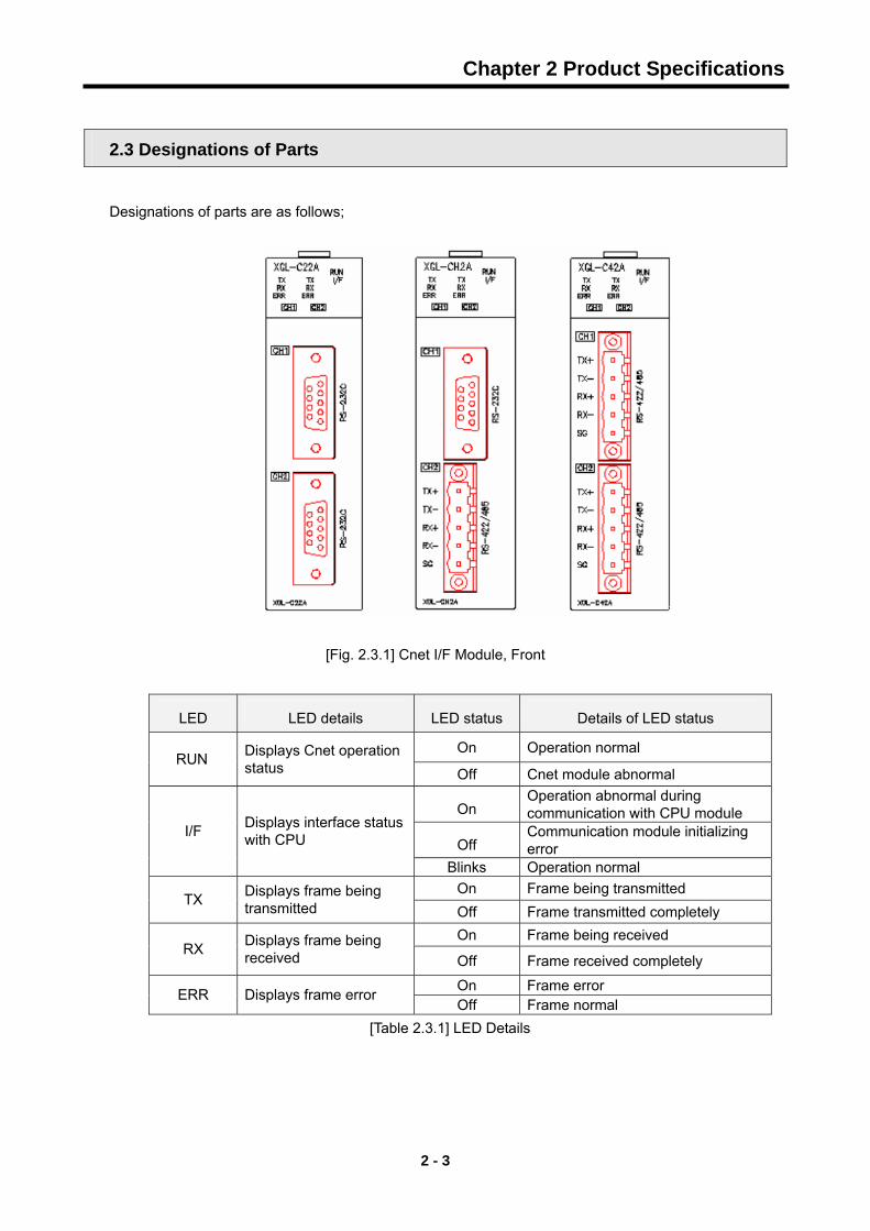
2.3 Designations of Parts
Designations of parts are as follows;
[Fig. 2.3.1] Cnet I/F Module, Front
LED LED details LED status Details of LED status
On Operation normal RUN Displays Cnet operation
status Off Cnet module abnormal
On Operation abnormal during communication with CPU module
Off Communication module initializing error
I/F Displays interface status with CPU
Blinks Operation normal On Frame being transmitted
TX Displays frame being transmitted Off Frame transmitted completely
On Frame being received RX Displays frame being
received Off Frame received completely
On Frame error ERR Displays frame error Off Frame normal
[Table 2.3.1] LED Details

Chapter 2 Product Specifications
2 - 4
2.4 Cable Specifications
When using communication channel, RS-422 or RS-485, twisted pair cable for RS-422 shall be used in consideration of communication distance and speed. [Table 2.4] describes recommended specifications of cable. Also when using other cable than recommended, the cable conforming to characteristics in [Table 2.4] shall be used. - Product : Low Capacitance Lan Interface Cable - Type : LIREV-AMESB - Size : 2P X 22AWG(D/0.254 TA) - Manufacturer: LS Cable
Test item Unit Characteristics Test conditions
Conductor resistance Ω/km 59 or less Normal temp.
Withstanding voltage(DC) V/1min Withstands for 1 min. at
500V In air
Insulation resistance MΩ-km 1,000 or more Normal temp
Static electricity capacity Pf/M 45 or less 1kHz
Electric
characteristics
Characteristics
impedance Ω 120 ± 12 10MHz
Item Single Cable
Cores Pair 2
Size AWG 22
Composition NO./mm 1/0.643 Conductor
Outer dia. mm 0.643
Thickness mm 0.59
Characteristics
of appearance.
Insulator Outer dia. mm 1.94
[Table 2.4.1] Standard of Twisted Pair Cable
[Fig. 2.4.1] Structure
Braided
Ground line
AL/MYLER TAPE
Conductor
Insulator
Sheath

Chapter 3 Performance Specifications
3 - 1
Chapter 3 Performance Specifications
3.1 Operation Mode Setting
The operation mode of XGT Cnet is decided by the basic communication parameters. It operates
separately from each communication port with the operation modes available as described below;
- Server Mode
Operates as a server in the network. XGT server and Modbus server are optional.
XGT server: dedicated communication protocol supported, memory Read/Write available.
Modbus server
Modbus protocol supported, RTU/ASCII type optional.
Setting necessary for conversion between Modbus protocol memory area and XGT
memory area.
XG5000 service (remote 1/2 step connection) functions supported at a time.
- P2P (Client) Mode
Operates as a client in the network.
Dedicated communication protocol and Modbus protocol supported.
Up to 64 communication blocks can be specified for 1 Cnet module to define the independent
operation.

Chapter 3 Performance Specifications
3 - 2
3.2 Channel Operation during Normal Run
Each communication port operates independently to allow simultaneous Tx/Rx in separate
transmission specifications. Therefore, transmission specifications can be set per RS-232C and RS-
422 channel, and the operation is started and stopped according to channels. Data flow of each
channel is as below.
RS-422 channelPLC CPU
TX
RX
RX
TX
RS-232C channel
RS-422 cable
RS-232C cable
[Fig. 3.2.1] Data Flow of Each Channel
Notes
[Note 1] Mode change during operation is unavailable. In order to change the mode, download the
basic communication parameters and reset the communication module.
[Note 2] Cnet I/F module supports only the separate mode.

Chapter 3 Performance Specifications
3 - 3
3.3 Channel Operation in Diagnosis Mode (Loop-Back)
Loop-Back diagnosis is a function to check if communication channel normally operates by itself
without connection with external devices, which is available when the diagnosis service is executed.
For the details of its operation method, see ‘Chapter 9 Diagnosis Function’.
3.4 Method of Serial Interface
3.4.1 RS-232C Interface
Channel RS-232C uses 9-pin connector (Female) for communication with external devices. The
names and functions of pins and data directions are as shown in the figure below.
Pin No. Name Contents Signal Direction (Cnet I/F module
↔ external device)Description
1 CD Carrier Detect Reports carrier detection of DCE to DTE
2 RxD Received Data Received data signal
3 TxD Transmitted Data Transmitted data signal
4 DTR Data Terminal Ready
Reports ready communication of DTENote1 to DCE Note2
5 SG Signal Ground Ground line for signal
6 DSR Data Set Ready Reports ready communication of DCE to DTE
7 RTS Request To Send DTE asks DCE to send data
8 CTS Clear To Send DCE asks DTE to send data
9 RI Ring Reports ringing tone received from DCE to DTE
[Fig. 3.4.1] RS-232C 9-pin Connector Standard
Channel RS-232C can communicate with external devices directly and also with remote communication
devices using modem. When connecting modem, communication type of RS-232C must be set to
‘modem’ with XG-PD, and when not using modem, it must be set to null modem
Notes
[Note1] DTE: Data Terminal Equipment (Cnet I/F module)
[Note2] DCE: Data Communication Equipment (external modem)

Chapter 3 Performance Specifications
3 - 4
1) How to connect RS-232C connector during modem connection
This module can communicate with devices of long distance as connected with modem. Modem and
RS-232C channel shall be connected as in [Fig. 3.4.2] below.
Cnet (9-PIN) Modem side (25-PIN)
Pin No. Name Connection No. and signal direction
Name Pin No.
1 CD CD 8
2 RXD RXD 3
3 TXD TXD 2
4 DTR DTR 20
5 SG SG 7
6 DSR DSR 6
7 RTS RTS 4
8 CTS CTS 5
9 RI[Note]
RI 22
[Fig 3.4.2] Cable Connection Between RS-232C and Modem
[Note] No.9, RI signal is not used in Cnet I/F module.
2) How to connect connector for RS-232C in null modem mode
In null modem mode, the connector can be connected in 3-line type as below.
Cnet(9-PIN) Computer/communication devices
Pin No. Name Connection No. and signal direction
Name
1 CD CD
2 RXD RXD
3 TXD TXD
4 DTR DTR
5 SG SG
6 DSR DSR
7 RTS RTS
8 CTS CTS
9 RI
RI [Fig. 3.4.3] 3-line Type of Connection (no handshake)

Chapter 3 Performance Specifications
3 - 5
3.4.2 RS-422 interface
Channel RS-422 uses 5-pin connector (Terminal Block) for communication with external devices. The names and functions of pins and data directions are as shown in [Fig. 3.5] below
Pin No. Name Signal Direction (Cnet<--> external device) Description
1 TX+ Transmitted data (+)
2 TX- Transmitted data (-)
3 RX+ Received data (+)
4 RX- Received data (-)
5 S.G(SG) Ground line for signal
[Fig. 3.4.4] RS-422 5-pin Connector Standard Channel RS-422 is designed available to connect RS-422 and RS-485(multi-drop) with external devices. When RS-422 channel is used as multi-drop, set each channel’s communication type to RS-485 on the basic setting menu of XG-PD, and use the terminal of RS-422 connected as shown in [Fig. 3.7]. [Fig. 3.4.5] shows an example of connecting communication cable in RS-422 communication
Cnet(5-Pin)
Pin No. Name Signal Direction
(Cnet<---> external device) External communication
device
1 TX+ RX+
2 TX- RX-
3 RX+ TX+
4 RX- TX-
5 S.G(SG)
S.G
[Fig. 3.4.5] RS-422 Connection
Cnet(5-Pin)
Pin No. Name Signal Direction
(Cnet<---> external device)
External communication
device
1 TX+ RX+
2 TX- RX-
3 RX+ TX+
4 RX- TX-
5 S.G(SG)
S.G
[Fig. 3.4.6] RS-485 Connection
[Fig. 3.4.6] shows how to connect RS-485 multi-drop communication. In case of multi-drop communication, to connect with external devices, TX+ and RX+, RX- and TX- of RS-422 channel shall be connected with each other. At this time half-duplex communication is run sharing Tx/Rx line, so the applicable port shall be applied as set to RS-485 in XG-PD.

Chapter 4 Installation and Test Operation
4 - 1
Chapter 4 Installation and Test Operation
4.1 Installation Environment
This product is of high reliance regardless of installation environment. However, for the sake of
reliance and stability of the system, please pay attention to those precautions described below.
1) Environmental Conditions
- To be installed on the control panel waterproof and dustproof.
- No continuous impact or vibration shall be expected.
- Not to be exposed to the direct sunlight.
- No dew shall be caused by rapid temperature change.
- Ambient temperature shall be kept 0-55 . ℃
2) Installation Work
- No wiring waste is allowed inside PLC when wiring or drilling screw holes.
- To be installed on a good location to work on.
- Don’t let it installed on the same panel as a high-voltage device is on.
- Let it kept at least 50 ㎜ away from duct or near-by module.
- To be grounded in an agreeable place free from noise.
4.2 Precautions for Handling
The system configuration with Cnet I/F module shall be performed under the following precautions.
1) Don’t let it dropped or shocked hard.
2) Don’t remove PCB from the case. It will cause abnormal operation.
3) Don’t let any foreign materials including wiring waste inside the top of the module when wiring.
4) Get rid of foreign materials if any.
5) Don’t install or remove the module while powered on.
6) Use standard cable only and let it installed within the maximum distance specified.
7) Let the communication cable free from the surge and inductive noise generated by or from the
alternating current.
8) Don’t let wiring too close to hot device and material or in direct contact with oil for long, which will
cause damage or abnormal operation due to short-circuit.
9) For wiring with pipes, the pipes need grounding.

Chapter 4 Installation and Test Operation
4 - 2
4.3 Operation Sequence The sequence of the product from installation to operation will be described below. After the product
installation is complete, install and configure the system to be operated as specified in the following
sequence.
Operation Sequence
6 Install Cnet I/F module on the base.
Check the applicable base/slot position for exact
installation on the basic base.
6 Connect the communication device with Cnet I/F module
by means of cable.
With the cable bound, let the terminal resistance
processed applicably.
6 With power On, check the LED status of the communication
module.
Check if the interface of the communication module
is normal with CPU.
6 Perform basic setting and P2P setting in XG-PD.
Specify applicable parameters to network
configuration in XG-PD and then download the
parameters.
6 Let the link enabled in XG-PD.
6 Start Run
Notes
1) Station number of Cnet I/F module is not necessary to set due to hardware properties.
Use XG-PD to specify basic settings necessary for station number and Cnet communication.

Chapter 5 System Configuration
5 - 1
Chapter 5 System Configuration
Cnet I/F module is used for CPUH and CPUS both. Up to 24 modules can be mounted on the main and expansion bases, and all 24 modules can be used using a dedicated protocol. However, only 8 modules are available to use P2P service. Various communication systems can be configured via this module in accordance with application fields. This chapter describes examples of system configurations which are available or unavailable for the application fields.
5.1 Available System Configurations
5.1.1 1:1 connection (no modem) to PC (HMI)
PC(HMI) and Cnet I/F module are connected via RS-232C or RS-422 channel in 1:1 connection system with PC (HMI) or PLC not through modem. Most PC(HMI)s are operated as client stations and Cnet I/F modules are operated as sever stations that respond the request of PC(HMI). Since no modem is applied, communication distance is max.15m via RS-232C channel and max.500m via RS-422 channel. Operation mode of Cnet I/F module shall be set as agreed with communication type of PC(HMI).
[Fig. 5.1.1] 1:1 communication system with PC 5.1.2 1:1 dedicated modem connection to PC (HMI)
PC(HMI) and the module are connected through dedicated modem via RS-232C channel in 1:1 connection system. Most PC(HMI)s are operated as client stations and Cnet I/F modules are operated as sever stations that respond the request of PC(HMI). Since modem is applied to go through, RS-232C channel shall be set to dedicated modem for long-distance communication. Operation mode of this module shall be set as agreed with communication type of PC(HMI).
[Fig. 5.1.2] Dedicated modem communication with PC
XGT PLCCnet
RS-232C/RS-422 communication
HMI S/W
XGT PLCCnet
RS-232C communication
HMI - PC (GLOFA VIEW)

Chapter 5 System Configuration
5 - 2
5.1.3 Modem connection to PC & Communication between Cnet I/F modules
♦ PC and Cnet #1 station are connected through modem via RS-232C channel.
♦ Cnet #1 station ~ N station carry out communication between Cnet I/F modules via RS-422
channel.
♦ PC is operated as client station of Cnet #1 station.
♦ Cnet I/F module can connect with max. 32 stations (RS-422/485 communication).
♦ RS-232C channel of Cnet I/F module is set to sever station and RS-422 channel of Cnet I/F
module is set to client station.
♦ Dedicated modem or dial-up modem is available to use.
[Fig. 5.1.3] Dedicated modem communication with PC
Module setting
Type RS-232C RS-422 Station No.
P2P PLC Cnet #1 station XGT Server
XGT Client 1
Cnet #2~#31 station Not used XGT Server 2~31
[Table 5.1.1] Module Setting Table for Station No.
XGT PLC Cnet # 1 station
XGT PLC Cnet # N station
XGT PLC Cnet # 2 station
RS-232C communication RS-422 communication
HMI – PC

Chapter 5 System Configuration
5 - 3
5.1.4 Dedicated communication with PC (HMI) & Other company’s RS-422 communication
♦ Null-modem communication with PC (HMI) via RS-232C channel is available.
♦ PC (HMI) is operated as client station and Cnet I/F module RS-232C channel is operated as XGT
server.
♦ Cnet I/F module RS-422 channel is operated in P2P mode.
♦ Display data is transmitted to display modules of mosaic panel via Cnet RS-422 channel.
♦ Display transmission data can be read in PC.
[Fig. 5.1.4] 7-Segment Operation system for RS-422
Module setting
Type RS-232C RS-422 Station No.
PLC Cnet #1 station XGT Server P2P 1
[Table 5.1.2] Module Setting Table for Station No
XGT PLC Cnet # 1 station
HMI - PC
RS-232C communication
RS-422 communication
RS-422 communication

Chapter 5 System Configuration
5 - 4
5.1.5 Optical modem communication for mobile communication
♦ Optical modem communication system for Cnet communication on body in lineal motion.
♦ Dedicated mode communication or P2P communication with monitoring device.
♦ RS -232C/RS-422 communication with optical modem.
♦ Dedicated client/sever communication between Cnet I/F modules.
♦ Optical modem connected with Cnet I/F module on mobile body can communicate with the other
optical modem only when positioned in communication available
♦ Main application: Parking tower
[Fig. 5.1.5] Optical modem communication system
XGT PLC Cnet # 1 station
Monitoring device
RS-232C communication
RS-422 communication
XGT PLC Cnet # 3 station
XGT PLC Cnet # 2 station
XGT PLC Cnet # 4 station
Optical modem
Mobile body
RS-232C communication
RS-232C communication
RS-232C communication
Optical modem
Optical modem
Optical modem

Chapter 5 System Configuration
5 - 5
5.1.6 Wireless modem communication for communication between revolution bodies
♦ Wireless modem communication system for Cnet communication on body in revolution motion.
♦ RS-232C communication with wireless modem.
♦ Dedicated client/sever communication between Cnet I/F modules.
♦ RS-232C channel of Cnet I/F module is dedicated modem mode.
[Fig. 5.1.6] Wireless modem communication system
Module setting
Type RS-232C RS-422 Station No.
Dedicated modeXGL-CH2A
User mode Not used 1 & 2
[Table 5.1.3] Setting details between communication modules
RS-232C communication RS-232C communication
XGT PLC Cnet # 1 station
XGT PLC Cnet # 2 station
Wireless modem Wireless modem

Chapter 5 System Configuration
5 - 6
5.1.7 TM/TC communication system
♦ Long-distance communication with remote sever PLC via dedicated modem.
♦ Dedicated modem communication via RS-232C channel set to dedicated modem mode.
♦ Dedicated client/sever communication between Cnet I/F modules.
♦ 8 Cnet I/F modules can be mounted on TM client PLC.
[Fig. 5.1.7] TM/TC dedicated modem system

Chapter 5 System Configuration
5 - 7
5.2 Unavailable System Configurations
5.2.1 Dial-up modem communication between Cnet I/F modules
♦ Cnet I/F module has no function to make telephone calls.
♦ Cnet I/F module has only function to answer telephone calls.
♦ Dial-up modem communication between Cnet I/F modules is unavailable.
[Fig. 5.2.1] Dial-up modem communication between Cnet I/F modules
XGT PLC Cnet # 1 station
XGT PLC Cnet # 2 station
Dial-up modem Dial-up modem
Relay station
Public line Public line
RS-232C communication RS-232C communication

Chapter 5 System Configuration
5 - 8
5.2.2 XG5000 connection using RS-422 channel of Cnet I/F module
♦ XG5000 service of Cnet I/F module supports only RS-232C channel.
♦ XG5000 connection via RS-422 channel is unavailable.
♦ Setting of Cnet’s station number in XG5000 remote connection is unavailable.
♦ XG5000 connection is available only for Cnet #1 station as shown in [Fig. 5.2.2].
[Fig. 5.2.2] XG5000 connection via RS-422 channel
XG5000 / XG-PD remote connection
XGT PLC Cnet # 1 station
XGT PLC Cnet # 2 station
XGT PLC Cnet # N station
Connection available Connection
unavailable
Connection unavailable
Sever setting P2P (client) setting Sever setting

Chapter 6 Basic Communication Parameters Setting
6 - 1
Chapter 6 Basic Communication Parameters Setting
6.1 Communication Module Registration
In order to use Cnet I/F module, communication parameters shall be specified in XG-PD. And for
system setting of Cnet I/F module positioned at an optional place, its applicable module shall be
registered in XG-PD. How to register the optionally positioned Cnet I/F module depends on On/Off line
status as described below.
1) Off-line registration of Cnet I/F module
In order to set the communication module and specify communication related parameters with
PLC disconnected, select the base and the slot position to register Cnet I/F module on the XG-
PD “Basic Setting Window” to display “Communication Card Setting” Window, where Cnet I/F
module shall be registered on the desired base and slot position.
[Fig. 6.1.1] Cnet Module Registration Screen

Chapter 6 Basic Communication Parameters Setting
6 - 2
2) On-line registration of Cnet I/F module On-Line
In order to register the communication module through XG-PD in on-line status, first of all, let PLC
CPU connected where the communication module is installed.
Select “On-Line Connect Setting” for communication setting and then go through “On-Line
Connect” to select Local Connect (or Remote 1/2 Stage Connect). If connected normally,
submenu of “On-Line” menu will be active, and there select “On-Line IO Information Read” to
automatically display all the communication modules in main base and extended base.
[Fig. 6.1.2] Cnet IO Information Read Screen
At this moment, if the off-line registered module is different from the information of the presently
connected PLC, or different from the type of the communication module prepared in the previous
project, the following message will appear for the user to confirm the change.
[Fig. 6.1.3] Message Window of IO Information Change
After the communication module is registered as described above, the communication module
registered will be displayed on the list.

Chapter 6 Basic Communication Parameters Setting
6 - 3
[Fig. 6.1.3] Communication module registration complete screen

Chapter 6 Basic Communication Parameters Setting
6 - 4
6.2 Transmission Specification Settings
Transmission specifications of transmission speed and data type such as data/stop bit shall be
specified in order to use Cnet I/F module. Select the transmission specifications as identical to those
of the system to be used for basic setting items of the registered Cnet I/F module.
Specified basic setting values will be saved in PLC CPU, and will not be changed until overwritten. In
addition, even if Cnet I/F module is replaced with a new module, the basic setting values previously
specified and saved in CPU will be automatically applied to the new module as well.
The basic communication setting parameters even if downloaded will not be directly applied to Cnet.
In order to apply the changed or newly specified basic settings, reset the communication module.
6.2.1 Setting items
When setting Cnet communication parameters, the user shall specify the items as specified in
[Table 6.1].
Items Setting Value Basic Value Remarks
Communication type RS-232C / RS-422 / RS-485 RS-232C
Surely register communication type
of each channel Communication
speed 300/600/1200/1800/2400/3600/4800/7200/9600/19200/38400/57600/64000/115200 9600
DATA BIT 7/8 8
STOP BIT 1/2 1 Data
type PARITY
BIT None/Even/Odd NONE Check detailed information
Modem type Null modem / Exclusive modem / Dial-up modem Null modem
Dedicated XGT communication XGT server
RTU/ASCII server Exclusive service
driver Modbus
DI/DO/AI/AO area
XGT server (Dedicated XGT communication)
Check detailed information
Station No. 0 ~ 31 0 Commonly used for all services
[Table 6.1] Basic setting items for Cnet
Cnet I/F module provides 2 communication channels which need Cnet basic setting respectively.
RS-232 2Port, RS-232 1Port/RS-422 1Port and RS-422 2Port are available based on the communication
module.
Additional information for some details among the items described in [Table 6.1] is described below;

Chapter 6 Basic Communication Parameters Setting
6 - 5
1) Communication type
Communication type of XGT Cnet I/F module can be selected by changing the communication
module. The user needs to confirm the type of the desired Cnet I/F module to specify correctly for
each channel. If the specified communication type is different from the actual communication
module’s channel, it will follow the communication module’s channel type, which disenables normal
communication.
(1) Parity Bit Three types of parity bit can be specified for Cnet I/F module. Description of each parity bit is as
follows;
Parity Bit Type Description Remarks
None Parity bit not used
Even If one number of one byte is even, 0 is sent to the parity bit
Odd If one number of one byte is odd, 0 is sent to the parity bit
[Table 6.2] Parity Details
(2) Exclusive service driver Use driver selection item to select the operation mode of Cnet I/F module for each channel.
Each channel of Cnet I/F module separately operates as a server or client. Types and details of
operation modes available for each port are as follows;
Driver Type Description Remarks
P2P Applicable port operates as a client and executes communication through P2P parameters setting.
Refer to P2P setting
XGT server Operates as XGT server which supports dedicated XGT communication.
For exclusive service
Modbus ASCII server Operates as Modbus ASCII server For exclusive service
Modbus RTU server Operates as Modbus RTU server For exclusive service
[Table 6.3] Driver Details
XGT or Modbus server is selected for the operation mode of Cnet channel, loader service will
be supported as well as exclusive service.
A) XGT server
Supports memory Read/Write only for exclusive service.
B) Modbus ASCII/RTU server
Composed of Modbus protocol, it shall be selected when Cnet I/F module needs to
operate as a server.
For mapping between Modbus defined memory area and XGT memory area, additional
setting is necessary.
- Refer to “6.1 Exclusive Service” for details on Memory Mapping.

Chapter 6 Basic Communication Parameters Setting
6 - 6
6.2.2 Setting method
In order to operate Cnet I/F module in the mode applicable to the user defined communication
specifications, follow the sequence below. In the case of XGL-CH2A (RS232 1Port, RS422 1Port)
installed on base 0 and slot 3, it shall be set as below.
(1) Communication Specifications
Channel 1 : RS-232C, 9600 Bps, 8/1/None, null modem, XGT server, 1 station
Channel 2 : RS-422, 38400 Bps, 8/1/Odd, null modem, PTP, 2 station
First, execute XG-PD and then register the communication module Cnet on the applicable base
and slot position as necessary for setting.
[Fig. 6.2.1] Setting screen of communication module
Select “Cnet” on the basic setting window to display serial communication setting window.
Specify communication speed, communication type and station number for the applicable
channels respectively.

Chapter 6 Basic Communication Parameters Setting
6 - 7
[Fig. 6.2.2] Basic setting screen of Cnet communication for respective channels
Now, select the operation mode for each channel. On the Cnet module area of “Basic Setting
Window”, double click the item set to Cnet to display “Cnet Basic Setting” window, where the
mode is specified for each channel.
After basic communication parameters setting is complete, download it onto Cnet module.
Select [Online Connect Write Parameter] to display Parameter Download Window.
Select basic setting for the desired communication card to execute Write.
[Fig. 6.2.3] Parameter Download Window

Chapter 6 Basic Communication Parameters Setting
6 - 8
[Fig. 6.2.4] Parameter Write Setting
On basic setting, specify Cnet for each base and slot and then click Confirm to complete
Download.
Even if downloaded, the specified communication parameters will not be applied to Cnet module.
Surely reset the communication module for initialization and normal operation based on the
specified communication parameters.
Three methods are used to reset.
1. Select Online->Reset using XG-PD.
2. Switch on the CPU reset switch. (Refer to the CPU user’s manual.)
3. Restart the PLC power.

Chapter 7 Communication Functions
7 - 1
Chapter 7 Communication Functions
Communication functions available in Cnet I/F module can be classified into several services as
follows;
- Exclusive service
Without additional programming in PLC, information and data of PLC can be read or written in
PC and associated devices.
Able to operate as XGT server supporting exclusive XGT protocol and as Modbus server
supporting Modbus RTU/ASCII protocol as well.
- P2P service
Cnet I/F module can operate as a client on the network.
If a specified event occurs, correspondent station’s memory can be read or written.
Able to operate as XGT Client and Modbus Client.
Used for communication with other company’s devices not supporting XGT or Modbus protocol
and used for Tx/Rx of the frame desired by user.
Up to 64 P2P blocks separately operated can be defined.
- Loader service
With remote 1st stage/2nd stage connection used, monitoring/program downloading is available
for remote PLC.
7.1 Exclusive Service
7.1.1 Introduction
Through this exclusive service function built-in Cnet I/F module, information and data of PLC can
be read or written in PC and associated devices without additional programming in PLC.
It operates as a sever in communication network and responds to memory Read/Write request
conforming to exclusive XGT protocol in external devices or PC, or conforming to Modbus protocol.
In order to use the exclusive service, select the operation mode for the channel used for server
among Cnet channels 1 and 2 when setting basic communication.
It supports XGT server and Modbus server which responds to both RTU and ASCII format.

Chapter 7 Communication Functions
7 - 2
Since Cnet I/F module respective channel operates separately, it can not be set to other type of
server.
Refer to exclusive service related items in “Chapter 10 Diagnosis” for details on check and
diagnosis of normal operation of the exclusive service.
7.1.2 XGT Server
During the exclusive service, all the frames used in XGT server shall not exceed 256 Bytes. And
the characters used in all the frames are of ASCII code. If used as multi-drop, up to 32 stations can
be connected with. Be careful not to set the duplicated station number to the identical network
when setting station number. Communication speed/stop bit/parity bit/data bit of all the Cnet I/F
modules shall be surely identical on the network if used as multi-drop. XGT server supports only
the memory Read/Write function of the Exclusive XGT protocol.
7.1.3 Modbus Server
It is used when the correspondent device to communicate with operates as Modbus Client.
It supports both Modbus’s ASCII Mode and RTU Mode, which can be specified in the operation
mode of basic setting window.
[Fig. 7.1.1] Basic setting screen of Modbus server
Modbus instructions that Modbus RTU/ASCII driver supports and the maximum response data are
as described in the table below.

Chapter 7 Communication Functions
7 - 3
Correspondent client device shall request within the range described in the table below.
For example, bit Read request is available up to 2000 bits, and bit Write request is available up to
1968 bits (using Modbus RTU).
Code Purpose Address Max. Response data
01 Read Coil Status 0XXXX 2000 Coils
02 Read Input Status 1XXXX 2000 Coils
03 Read Holding Registers 4XXXX 125 Registers
04 Read Input Registers 3XXXX 125 Registers
05 Force Single Coil 0XXXX 1 Coil
06 Preset Single Register 4XXXX 1 Register
15 Force Multiple Coils 0XXXX 1968 Coils
16 Preset Multiple Registers 4XXXX 120 Registers
[Table 7.1.1] Modbus Instruction Code
For the request of each instruction code, applicable area shall be set for XGT PLC memory.
It is available through “Modbus Setting” window as shown in the figure below which is displayed if
“Setting” button clicked after active with Modbus ASCII server/RTU server selected on the
“Modbus setting of Cnet operation mode” window.
[Fig.7.1.2] Setting window of Modbus server memory
Details of respective setting item are as follows;
Item Description Remarks
DI area address XGT address applicable to digital input area Bit address
DO area address XGT address applicable to digital output area Bit address
AI area address XGT address applicable to analog input area Word address
AO area address XGT address applicable to analog output area Word address
[Table 7.1.2] Details of Modbus Area
The address value set in the respective item is the base address of the applicable area.

Chapter 7 Communication Functions
7 - 4
The screen above shows that DI area is assigned from MX1000, and AO area from PW200.
Input value of Base Address shall be inside the effective area such as %M,P, etc.
Since Modbus address is 1 ~ 9999 (decimal), bit I/O area’s size will be 9999/8 = 1249.875 bytes.
And Word I/O area’s size will be 9999*2 = 19998 bytes.
If the user set the bit output (0XXXX) area’s Base Address to 0, Modbus bit area 00001 will
respond to 0th byte, 0th bit, and 00002 to 0th byte, 1st bit.
7.2 P2P Service
7.2.1 Introduction P2P service executes client operation of the communication module as realized with
parameters setting which was with instruction blocks. Four P2P instructions available in Cnet
I/F module are Read/Write/Send/Receive.
P2P service’s registration and edit is executed in XG-PD where up to 8 P2P parameters can be
set. Respective P2P parameter is composed of up to 64 P2P blocks.
The following shows an example of P2P parameters setting window in XG-PD.
[Fig. 7.2.1] Setting example of P2P parameters
P2P parameters registration window Up to 8 P2P parameters can be set Multiple P2P parameters can be set for an identical Cnet I/F module
However, Enable is available only for 1 parameter among the multiple P2P parameters for the identical Cnet I/F module
Respective P2P parameter is composed of P2P channel, P2P block and user defined frame
P2P edit window Up to 64 P2P blocks can be registered and edited.

Chapter 7 Communication Functions
7 - 5
7.2.2 Configuration of P2P parameters
In order to use P2P service the user needs to execute setting for the operation desired on the
P2P parameters window. P2P parameters are composed of 3 kinds of information as shown in
the figure below;
[Fig. 7.2.2] Configuration screen of P2P parameters
- P2P channel P2P channel setting to define the communication protocol of the P2P service to execute XGT/Modbus available Separate setting for respective channels. Applied only if basic setting’s “P2P driver” is None.
- P2P block 64 P2P blocks setting separately operated
- User defined frame Registration of user defined frame
7.2.3 Channel information
Cnet I/F module provides 2 communication channels (channel 1, channel 2) separately operated. Driver type of the channels can be defined respectively for P2P service. If P2P channel is selected on P2P setting window, P2P channel setting window will appear as below.

Chapter 7 Communication Functions
7 - 6
[Fig. 7.2.3] P2P channel setting screen
If the channel with P2P used is selected, “P2P channel setting” window will appear for the user to
define P2P driver for the applicable channel.
[Fig. 7.2.4] Setting screen of channel driver with P2P used
Drivers and details available in XGT Cnet are as follows; Drivers Details
None P2P service not used User defined frame Used for Tx/Rx of user defined frame as desired XGT client Selected for Read/Write of XGT memory Modbus ASCII client Selected if operated as Modbus Client and used in ASCII Mode Modbus RTU client Selected if operated as Modbus Client and used in RTU Mode
[Table 7.2.1] Drivers
If XGT or Modbus is selected as P2P driver for the communication channel, user defined frame
can not be available.

Chapter 7 Communication Functions
7 - 7
* How to use Modbus driver
Code Purpose Modicon PLC Data Address Remarks
01 Output Contact Status Read (Read Coil Status) 0XXXX(Bit-Output) Bit Read 02 Input Contact Status Read (Read Input Status) 1XXXX(Bit-Input) Bit Read 03 Output Register Read (Read Holding Registers) 4XXXX(Word-Output) Word Read04 Input Register Read (Read Input Registers) 3XXXX(Word-Input) Word Read05 Output Contact 1 Bit Write (Force Single Coil) 0XXXX(Bit-Output) Bit Write
06 Output Register 1 Word Write (Preset Single Register)
4XXXX (Word-Output) Word Write
15 Output Contact Continuous Write (Force Multiple Coils)
0XXXX (Bit-Output) Bit Write
16 Output Register Continuous Write (Preset Multiple Register)
4XXXX (Word-Output) Word Write
[Table 7.2.2] Codes of Modbus instructions and data

Chapter 7 Communication Functions
7 - 8
7.2.4 Block information
If P2P block of applicable parameter is selected on P2P parameters setting window, P2P block
setting window will be displayed.
[Fig. 7.2.5] P2P block setting screen
Up to 64 separate blocks can be set. Select an optional block to specify the applicable block
operation by selection of a instruction as shown below;
[Fig. 7.2.6] P2P instruction screen
Setting items and details of respective instructions are as follows;
1) Read instruction Used to read and save correspondent station’s optional area, commonly regardless of driver type.
Its basic configuration is as shown below;
Chapter 7 Communication Functions
7 - 9
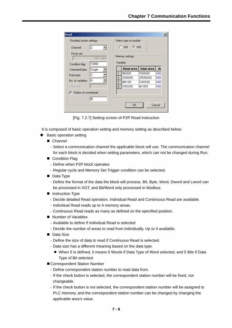
[Fig. 7.2.7] Setting screen of P2P Read instruction
It is composed of basic operation setting and memory setting as described below; Basic operation setting
Channel - Select a communication channel the applicable block will use. The communication channel
for each block is decided when setting parameters, which can not be changed during Run. Condition Flag - Define when P2P block operates - Regular cycle and Memory Set Trigger condition can be selected. Data Type - Define the format of the data the block will process. Bit, Byte, Word, Dword and Lword can
be processed in XGT, and Bit/Word only processed in Modbus. Instruction Type - Decide detailed Read operation. Individual Read and Continuous Read are available. - Individual Read reads up to 4 memory areas. - Continuous Read reads as many as defined on the specified position. Number of Variables - Available to define if Individual Read is selected - Decide the number of areas to read from individually. Up to 4 available. Data Size - Define the size of data to read if Continuous Read is selected. - Data size has a different meaning based on the data type.
When 5 is defined, it means 5 Words if Data Type of Word selected, and 5 Bits if Data Type of Bit selected.
Correspondent Station Number - Define correspondent station number to read data from. - If the check button is selected, the correspondent station number will be fixed, not
changeable. - If the check button is not selected, the correspondent station number will be assigned to
PLC memory, and the correspondent station number can be changed by changing the applicable area’s value.

Chapter 7 Communication Functions
7 - 10
Memory Setting
Area to read - Set the correspondent area to read. - Set as many as variables with input value which will be different based on drivers. - XGT client
Input M100 to read data of correspondent %MW100. - Modbus client
Input 30010 to read data of correspondent AI 10 address. Area to save - Set the area to save the read data on. - Set as many as variables with input value which will be different based on drivers. - Input P100 to save the read data on %PW100.

Chapter 7 Communication Functions
7 - 11
In order to read and save %MW250 and %MW260’s 1 Word of the correspondent station No. 7 on %PW100 and %PW130 when TW01’s No. 0 bit is set via the channel 2, its setting will be as follows;
[Fig. 7.2.8] Setting screen of P2P Read instruction
2) Write instruction Used to write data on optional correspondent station’s area desired, commonly regardless of driver
type. It supports Continuous Write and Individual Write, where data can be written on up to 4
individual areas. Its basic configuration is as shown below;
[Fig. 7.2.9] Setting screen of P2P Write instruction

Chapter 7 Communication Functions
7 - 12
Details of respective input items are as described below;
Basic operation setting Channel - Select a communication channel the applicable block will use. The communication channel
for each block is decided when setting parameters, which can not be changed during Run.
- For normal operation of P2P block, the applicable channel shall be set to P2P used with a
driver selected. Condition Flag - Define when P2P block operates - Regular cycle and Memory Set Trigger condition can be selected.
Data Type - Define the format of the data the block will process. Bit, Byte, Word, Dword and Lword can
be processed in XGT, and Bit/Word only processed in Modbus.
Instruction Type - Decide detailed Write operation. Individual Write and Continuous Write are available. - Individual Write writes up to 4 memory areas. - Continuous Write writes as many as defined on the specified position.
Number of Variables - Available to define if Individual Write is selected - Decide the number of areas to write on individually. Up to 4 available.
Data Size - Define the size of data to write if Continuous Write is selected. - Data size has a different meaning based on the data type.
When 5 is defined, it means 5 Words if Data Type of Word selected, and 5 Bits if Data
Type of Bit selected
Correspondent Station Number - Define correspondent station number to write data on. - If the check button is selected, the correspondent station number will be fixed, not
changeable. - If the check button is not selected, the correspondent station number will be assigned to
PLC memory, and the correspondent station number can be changed by changing the
applicable area’s value.
Memory Setting Area to read - Set the area of the value to write. - Set as many as variables with input value which will be different based on drivers. - XGT client
Input P220 on the save area to write data on %PW220. Area to save - Set the correspondent area to write on, which will be different based on drivers. - Input M130 to save on %MW130 in the case of XGT client. - Input 40054 to save on AO 54 in the case of Modbus client

Chapter 7 Communication Functions
7 - 13
In order to read and write 10 Words of the correspondent station No. 2 in the memory starting
from %MW125 on the correspondent %PW200 when MW10’s No. 2 bit is set via the channel 2,
its setting will be as follows.
[Fig. 7.2.10] Setting screen of P2P Write instruction
3) Send instruction This instruction is used to send the optional frame to an external device to connect with through not
XGT/Modbus protocol but unspecific communication method.
Only one frame shall be selected to use for one Send instruction, and memory setting shall be
specified in this instruction for applicable frame’s size-fixed/size-changeable variable.
The frame to send shall be surely specified before the instruction is used.
[Fig. 7.2.11] Setting screen of P2P Send instruction
Details of respective items above are as described below;
Basic operation setting Channel
- Select a communication channel to send the desired frame through.

Chapter 7 Communication Functions
7 - 14
Condition Flag
- Define when the frame is to be sent.
Frame
- Select the name of the user defined frame to be used in applicable P2P block.
- Frame shall be defined prior to instruction registration. Selection available among the frames
registered as frames to send.
Memory Setting Items
Area to read - Specify the data position to configure the frame as information for the variable area inside Tx
frame.
- Input Word address. If the variable area of the frame is configured by reading data
from %MW200, then input M200.
- Define as many as variables inside the frame.
Size
- Set the size of data to be in the variable area inside Tx frame selected.
- It shall be of Byte, and defined as many as variables.
4) Receive instruction This instruction is used to receive some frames among those frames the correspondent station
sends. An identical frame can not be selected for respective P2P Receive instruction blocks. Only
one Receive instruction block can be decided for the received frame.
[Fig. 7.2.12] Setting screen of P2P Receive instruction
Basic operation setting Channel
- Select a communication channel to receive the frame through
Frame
- Select the name of the user defined frame to be used in applicable P2P block.

Chapter 7 Communication Functions
7 - 15
- Frame shall be defined prior to instruction registration.
- Selection available among the frames registered as frames to receive.
Memory Setting Items
Area to save
- Specify the position to save data on through setting variables if registered frame is
received.
- Define as many as variables inside the received frames.
- Received data size is of Byte.
7.2.5 User Defined Frame Information
Applicable Tx/Rx frames shall be defined if the frames desired by user are to be sent or the
frames among those on the network are to be received. This is available only in P2P service.
All the frames are composed of Head, Body and Tail which can be omitted respectively.
In XGT, user defined frames are displayed with group name and frame name whose details are
as follows;
Group
Group of frames with identical heads and tails
Group registration surely necessary for the frame registration
Frame
Composed of Head, Body and Tail
Tx/Rx frame shall be defined
Fixed and size-changeable variables can be added to Body
Frame is composed of lots of segments, and up to 4 variable segments can be registered
for a Body.
1) Type of segments
Head, Body and Tail of the frame are composed of lots of segments, which can be registered
on the frame edit window as below.
[Fig. 7.2.13] Setting screen of frame HEAD segment

Chapter 7 Communication Functions
7 - 16
Segments used to configure the frame are numeric constant, text constant, size-fixed variable
and size-changeable variable.
[Fig. 7.2.14] Setting screen of segment Add
Numeric Constant
Defined the part to be fixed as Constant among frames.
Value of the data item is Hex.
[Fig. 7.2.15] Screen of Segment Numeric Constant Add
Text Constant
Register Text Constant among frames.
Value of the data item is ASCII

Chapter 7 Communication Functions
7 - 17
[Fig. 7.2.16] Screen of Segment Text Constant Add
Size-fixed variable
Available only in the Body area of Rx frame.
Used to process data as big as defined among received frames
- Size is of Byte.
Check “Specify Memory” to save on PLC Memory.
- Conversion and swap are available.
[Fig. 7.2.17] Screen of Segment Size-Fixed Variable Add
Size-changeable variable
Available in the Body area of Tx/Rx frames.
Tx Frame
- Used to change the length of frame.
- Check “Specify Memory” to configure Tx frame with the data read from PLC memory.

Chapter 7 Communication Functions
7 - 18
Rx Frame - Used to process the size-changeable data among the received frames. - Registration available only in the last segment in the Body area. - Check “Specify Memory” to save the data for the applicable segment among the
received frames. Swap and conversion are available. Received data size is of Byte.
[Fig. 7.2.18] Screen of segment size-changeable variable edit
2) Data Conversion Processing In order to convert data from Hex to ASCII when frames are sent and received, or execute Byte swap, the applicable setting shall be specified on the frame edit window. Conversion
Hex To ASCII - Tx : converts read data from PLC memory to ASCII so to configure Tx frame. - Rx : converts received data to ASCII so to save. ASCII To Hex - Tx : converts read data from PLC memory to Hex so to configure Tx frame. - Rx : converts received data to Hex so to save.
[Fig. 7.2.19] Conversion setting screen of segment size-changeable variable

Chapter 7 Communication Functions
7 - 19
If 2 Words of PLC memory MW100 used for Tx frame configuration, is converted from Hex to ASCII with 0x34353637 saved on MW100, Tx frame’s applicable segment will be specified to “4567”. And when some of the received frames are saved as converted to Hex, 0x34353637 will be saved on PLC memory if the applicable area value is “4567”.
Swap 2 Bytes : 2 Bytes swap of applicable part among Tx/Rx frames 4 Bytes : 4 Bytes swap of applicable part among Tx/Rx frames 8 Bytes : 8 Bytes swap of applicable part among Tx/Rx frames
If 0x1234567811223344 is converted by respective methods above, its results are as follows;
- 2 Bytes swap : 0x3412785622114433 - 4 Bytes swap : 0x7856341244332211 - 8 Bytes swap : 0x4433221178563412
3) Tx frame
In order to send a frame to the outside, the desired Tx frame shall be registered. If not P2P XGT client driver but user defined frame is used, Tx frame setting example is as described below in the case of writing 4-Word data on starting M100 address in the correspondent station No.0. TX.Frame Head Body Tail
Frame 0x05 00 wSB 06%MW100 04 Size-
Changeable Variable
0x04 BCC
Remarks Numeric Constant
Text Constant
Text Constant
Text Constant
Text Constant
Hex To ASCII Conversion
Byte Checksum
ASCII Conversion
First of all, add the group of Tx frames.
[Fig. 7.2.20] Screen of Tx frame group Add

Chapter 7 Communication Functions
7 - 20
After the group edit window appears as below, input the group name of the Tx frames, and select
the frame type of “Tx”.
[Fig. 7.2.21] Setting screen of Tx frame group
Lots of frames can be registered for the applicable group. For this registration, select the group to
register Tx frame in and click the right mouse button to add the frame as shown in the figure
below.
[Fig. 7.2.22] Setting screen of Tx frame Add
Head, Body and Tail can be registered on the frame edit window.
[Fig. 7.2.23] Screen of Tx frame edit

Chapter 7 Communication Functions
7 - 21
Just one Head and one Tail exists for a group, however, lots of bodies can be registered. In
addition, while the Head and the Tail are omissible, the frame shall surely have a body.
- Head registration
While many segments can be added for Head, Numeric Constant or Text Constant is only
available for respective segments.
[Fig. 7.2.24] Registration screen of Tx frame Head
- Body registration.
Body can be composed of many segments with up to 4 size-changeable variables defined.
Body setting for TX.FRM.A on the frame edit window will be as follows;
[Fig. 7.2.25] Registration screen of Tx frame Body
- Tail registration
BCC can be registered in this item. Available BCC is as follows.
[Fig. 7.2.26] Registration screen of Tx frame Tail

Chapter 7 Communication Functions
7 - 22
Screen to display the complete registration of the example frame,
[Fig. 7.2.27] Tx frame setting complete screen
4) Rx frame In order to receive an optional frame, the Rx frame should be defined first. In case that ACK and NAK response frames are received for the wSB transmission frame, the register method is as follows. How to register the frame received will be as described below;
ACK.FRAME Head Body Tail Frame 0x06 01 wSB 03 BCC
Remarks Numeric Constant
Text Constant
Text Constant
Numeric Constant Byte Check Sum ASCII
NAK.FRAME Head Body Tail
Frame 0x15 01 wSB Size-Fixed Variable 03 BCC
Size(BYTE) 1 2 3 2 1 2
Remarks Numeric Constant
Text Constant
Text Constant (Error code) Numeric
Constant Byte Check Sum ASCII
First of all, add the group with the name of “ACK”,”NAK” for the frame registration.
[Fig. 7.2.28] Registration screen of ACK, NAK group received

Chapter 7 Communication Functions
7 - 23
Add the frame to the registered received frame group “ACK”.
- Head registration
[Fig. 7.2.29] Registration screen of ACK received frame Head
- Body registration
Register additionally the data to process in Body among received frames.
[Fig. 7.2.30] Registration screen of ACK frame Body
-Tail registration
[Fig. 7.2.31] Registration screen of ACK frame Tail
Add the frame to the registered received frame group “NAK”.
- Head registration
[Fig. 7.2.32] Registration screen of NAK received frame Head
- Body registration
Register additionally the data to process in Body among received frames.
Use fixed size variable if the data size is known, or use variable size variable if it is unknown.
[Fig. 7.2.33] Registration screen of NAK frame Body

Chapter 7 Communication Functions
7 - 24
-Tail registration
[Fig. 7.2.34] Registration screen of NAK frame Tail
Screen to display the complete registration of the example frame.
[Fig. 7.2.35] ACK, NAK received frame registration complete screen
7.2.6 P2P service operation
After P2P parameters are specified, download the parameters onto PLC CPU and start the P2P service. It is supposed that P2P parameters to download are already prepared and connection is available with the applicable PLC CPU.
1) P2P parameters downloading In order to download the prepared P2P parameters, select “On-Line Parameter Write” on XG-PD menu window to display the parameters downloading window, where registered basic setting, P2P parameters and HS link parameters can be selected.
[Fig. 7.2.36] Screen of P2P parameters Write

Chapter 7 Communication Functions
7 - 25
Among P2P 1 ~ 8, only the prepared P2P parameters will be displayed after sorted, where P2P
parameters to download will be selected.
Click Confirm to download the P2P parameters onto CPU.
2) P2P service start
Even after P2P parameters are downloaded, P2P shall be started in order to start the P2P service.
Select “On-Line – Link Enable” on the menu.
[Fig. 7.2.37] Setting screen of P2P Enable
Select P2P parameters to start on the “HS Link/P2P Enable” window. The P2P parameters
already checked is during run, whose P2P service will stop if cancelled.
In order to confirm normal downloading and normal P2P service operation, select “On-Line
System Diagnosis” on the menu. Refer to “Chapter 9 Diagnosis Function” for more details.

Chapter 7 Communication Functions
7 - 26
7.3 Remote Connection 7.3.1Introduction
If XG5000/XG-PD executed PC is located far from XGT-PLC, remote PLC program can be controlled for download, upload, debugging, monitoring, etc. through remote connection function of Cnet I/F module. Especially in case that XG5000 is located far away from PLC, PLC CPU can be conveniently accessible through telephoning, remote connection and computer linked modem connection functions in XG5000 via public line. Remote connection which is supported in Enet and Cnet of XGT PLC communication modules allows connection between networks to control remote PLC program via multi-steps connection conveniently. The remote connection via Cnet module is available for both 2 cases of remote connection between Cnet modules where XG5000 and PLC are directly connected via RS-232C and modem connection between XG5000 and PLC.
7.3.2 XG5000 remote connection
[Fig. 7.3.1] shows an example of remote connection between XG5000 and PLC via modem. As shown in the figure, this structure is required for connection with PLC via phone line, dedicated line modem or wireless modem if XG5000 operated PC is located far from PLC. In this case, XG5000 shall be connected via direct modem with Cnet I/F module and the modem shall be set as the connection type in connection option. Modem connection has two types of dedicated modem connection via dedicated line and dial-up modem connection via public line.
1) Dial-up modem connection
[Fig. 7.3.1] shows an example of dial-up modem connection. Dial-up modem connection is to connect dial-up modem with PC and Cnet I/F module via telephoning for remote connection through added function services to start/stop phone call. Namely, make a phone call first in XG5000 to apply remote connection after phone is connected, via PC linked modem of external or internal dial-up type, and via external modem for Cnet I/F module side.
[Fig. 7.3.1] Example of XG5000 remote connection via dial-up modem

Chapter 7 Communication Functions
7 - 27
Remote connection sequence via dial-up modem is as follows; (1) Set operation mode of RS-232C channel in Cnet I/F module to XGT server. (2) Set RS-232C channel operation of Cnet I/F module to dial-up modem and input modem
initializing instruction. (3) Execute the XG5000 program and select “On-Line Connect Setting” to display the
communication setting window, and there set “Connect Option Setting Connect Type” to Modem.
[Fig. 7.3.2] Setting screen of modem connection
(4) Select the setting button of “Communication Option Setting” to specify modem related details.
[Fig. 7.3.3] Setting screen of modem details
Notes Communication speed set in connection option is not for that of modem but for that between PC and modem. Communication speed of modem means the communication speed between modems which is automatically set as agreed with the telephoning quality of public line and speed of the correspondent station modem. The XG5000 remote connection shall use RS-232C channel with “RS-232C Dial-up Modem” specified on XG-PD communication basic setting so to write on XGT Cnet I/F module and then reset the module for its application. Other connection types than set for Cnet I/F module are identical to other units.
(5) Phone number shall be input as of the number of modem side linked to Cnet. Extension No.
and ‘,’ are available if flowed out from local via the extension.

Chapter 7 Communication Functions
7 - 28
(Ex.) If extension No. is ‘9’ : Set to 9, 0343-398-xxxx.
Notes
If modem connected with Cnet I/F module which is set to the correspondent station is via central exchanger, normal communication is unavailable. Namely, if separate extension No. is applied in receiving station, dial-up modem communication is not allowed.
(6) If the connection stage of remote 2 is selected, select the base No. and slot No. of the
remote stage 1’s communication module on the details item and the station No. of the remote
stage 2’s communication module. The station No. shall be input as specified in Cnet module.
Select remote stage 1’s communication channel for Cnet channel.
[Fig. 7.3.4] Setting screen of modem remote 2 stage
(7) Select Connect in On-line after Connect option setting for modem initializing.
(8) If COM channel of the modem is incorrectly set or connection with modem is abnormal, the
error message is displayed. In this case, inspect COM channel or modem connection.
(9) If telephoning is completed, XG5000 tries remote connection automatically and if remote
connection is completed, program Write and Run/Stop icon menus will be active.
(10) This means that remote 1 stage connection is completed just like the connection status that
RS-232C cable is connected as moved, where all functions on On-line menu are available.
Notes
For application of XG5000 after remote connection, On-line menu can be used as in local connection. Functions for program download/upload/monitor are available. PLC control via modem depends much on modem performance and phone line status. If phone line is in deficient status, connection may be released. In this case, try re-connection not immediately but in approx. 30 seconds starting from (1).

Chapter 7 Communication Functions
7 - 29
(11) To release connection in remote connection status, select Disconnect on On-line menu.
(12) If connection is released, XG5000 hangs up the phone automatically to disconnect it.
(13) If the phone is hung up normally, local and remote modem is restored to initial status to
allow remote connection again via telephoning.
2) Dedicated modem connection [Fig. 7.3.5] shows dedicated modem connection between PC and Cnet I/F module via dedicated line, where Cnet I/F module can be set to dedicated modem without telephoning stage differently from dial-up modem.
[Fig. 7.3.5] Connection diagram via dedicated modem speed
[Fig. 7.3.5] shows an example of dedicated modem connection via dedicated line or wireless modem / optical modem available also. Modem without public line shall be set as in dedicated modem as follows.
Remote connection sequence via dedicated modem is as follows. (1) Connect dedicated modem between PC and Cnet I/F module. (2) Set RS-232C channel of Cnet I/F module to XGT server. (3) Set RS-232C channel operation of Cnet I/F module to dedicated modem. (4) Execute the XG5000 program and select “On-Line Connect Setting” to display the
communication setting window, and there set “Connect Option Setting Connect Type” to Modem, and click the setting button to specify communication channel and transmission speed which are set in dedicated modem linked with PC. The communication speed shall be set identical to that of the dedicated modem.

Chapter 7 Communication Functions
7 - 30
[Fig. 7.3.6] Setting screen of dedicated modem (5) If the connection stage of remote 2 is selected, specify remote stage 1 & 2 related setting on
“Details” window as below.
[Fig. 7.3.7] Setting screen of dedicated modem remote stage 2
(6) XG5000 tries remote connection and if remote connection is completed, it means remote 1
stage connection is completed just like the connection status that RS-232C cable is connected as moved, where all functions on On-line menu are available.
Notes For application of XG5000 after remote connection, On-line menu can be used as in local connection. Functions for program download/upload/monitor are available. PLC control via modem depends much on modem performance and phone line status. If phone line is in deficient status, connection may be released. In this case, try re-connection not immediately but in approx. 30 seconds starting from (1).
(7) To release connection in remote connection status, select Disconnect on On-line menu. (8) If connection is released normally, Cnet I/F module and XG5000 are changed to initial mode
to allow re-connection when tried again starting from the clause No.(1).

Chapter 7 Communication Functions
7 - 31
(9) In addition to dedicated modem, optical modem and wireless modem also can be used equally for connection between XG5000 and Cnet, though communication medium between modems differs from each other.
7.3.3 Remote Connection between Cnet I/F Modules
[Fig. 7.3.8] shows an example of remote connection to PLC located far away when XG5000
and local PLC are connected to CPU via RS-232C cable, and RS-232C channel of Cnet I/F
module mounted on local PLC communicates with Cnet I/F module of remote PLC via
dedicated modem. As shown in the figure, XG5000 can control remote PLC program via
remote connection through modem communication function between Cnet I/F modules.
[Fig. 7.3.8] Remote connection between Cnet I/F modules
< Remote connection sequence >
1) Set RS-232C channel operation of Cnet I/F module to dedicated modem to operate as
XGT server.
2) Switch local connected PLC to stop mode.[Note]
Notes
If communication is overloaded, remote connection may fail. Surely switch PLC to STOP to stop communication prior to remote connection.
3) Execute the XG5000 program and select “On-Line - Connect Setting” to specify Connect
Type of RS-232C and Communication Channel as in local connection.

Chapter 7 Communication Functions
7 - 32
[Fig. 7.3.9] Setting screen of remote connection between PLCs
4) Select the connection stage of remote 1 and click the setting button to specify details. The station No. can be set on Details window. The station No. shall be input as specified in Cnet I/F module used to connect to remotely. Cnet channel shall be set to Cnet module’s communication channel located on the CPU local connection. The figure below shows the remote Cnet station number set to 22.
[Fig. 7.3.10] Setting screen of remote 1 stage connection between PLCs
5) XG5000 tries remote connection and if remote connection is completed, On-Line related functions will be active.
6) This means that remote 1 stage connection is completed just like the connection status that RS-232C cable is connected as moved, where all functions on On-line menu are available.
7) To release connection in remote connection status, select Disconnect on On-line.

Chapter 7 Communication Functions
7 - 33
8) If connection is released normally, Cnet I/F module and XG5000 are changed to initial
mode to allow re-connection when tried again starting from the clause No.(1). 9) In addition to dedicated modem, optical modem and wireless modem also can be used
equally for remote connection, though communication medium between modems differs from each other.
[Fig. 7.3.11] shows an example of remote connection via wireless modem. Connection method is the same as in the remote connection via the communication between Cnet I/F modules. When wireless modem is applied, the remote connection in 1 : N configuration where several remote Cnet I/F module stations are in existence is also available.
[Fig. 7.3.11] Remote connection via wireless modem

Chapter 8 XGT Dedicated Communication Function
8 - 1
Chapter 8 XGT Dedicated Communication Function
8.1 Dedicated Protocol Communication
8.1.1 Introduction
XGT Cnet dedicated communication is a function to execute dedicated communication with Cnet I/F
module itself, which will allow the user to configure the communication system easily as desired by
means of data Read/Write function and monitoring function of internal device area in CPU module. In
addition, it will be a very useful function for the user who wants to use the basic communication function
only such as internal device area Write/Read, monitor registration and execution with Cnet I/F module
only used to apply Cnet communication free of additional charge.
Cnet I/F module provides the following functions.
• Individual / Continuous Device Read
• Individual / Continuous Device Write
• Registration of Monitor Variable
• Execution of Monitor
• 1:1 connection (LS link) system configuration (Cnet I/F module: RS-232C)

Chapter 8 XGT Dedicated Communication Function
8 - 2
8.1.2 Frame Structure
1) Basic structure
(1) Request frame (external communication device → Cnet I/F module)
Header (ENQ) Sta.No. Instruction Instruction
Type Structurized data area Tail (EOT)
Frame Check(BCC)
(2) Response frame
A) ACK Response frame (Cnet I/F module → external communication device, if data is received normally)
Header (ACK) Sta.No. Instruction Instruction
Type Structurized data area or Null
code Tail
(ETX) Frame Check
(BCC)
B) NAK Response frame (Cnet I/F module → external communication device, if data is received
abnormally)
Header (NAK) Sta.No. Instruction Instruction
Type Error code (ASCII 4 Bytes) Tail (ETX)
Frame Check(BCC)
1) Figure data of all frames is displayed in ASCII code for hexadecimal figure unless specified additionally.
What is displayed in hexadecimal figures is as shown in the list below. • Station No. • Instruction type as of figures (= data type) when main instruction is R(r) and W(w) • All items indicating total data size in structurized data area • Instruction registration number for monitor registration and execution instruction • All contents of data 2) If hexadecimal data is applied, the Hex. type of data is indicated with ‘H’ attached in front of figures inside
frame like H01,H12345,H34,H12 & H89AB. 3) Available frame length is up to 256 Bytes. 4) Details of used control code are as follows; 5) If the instruction is of small letter (r), BCC value is added to Frame Check and if it is of capital letter (R), no
BCC value is added.
2) Sequence of instruction frame Response frame for Request Instruction is divided into ACK and NAK and sent in the following sequence.
Code Hex value Designation Control Detail
ENQ H05 Enquire Request frame’s Start code ACK H06 Acknowledge ACK response frame’s Start code NAK H15 Not Acknowledge NAK response frame’s Start code EOT H04 End of Text Frame End ASCII code used for Request ETX H03 End Text Frame End ASCII code used for Response
Notes
NAK Sta.No.
Instruc
tion
Error code ETX BCC(PLC NAK response)
Sta.No.
Instruction
Data or Null ETX BCCACK
Sta. No.
Instruction
Formatted Data EOT BCCENQ
(PLC ACK response)

Chapter 8 XGT Dedicated Communication Function
8 - 3
8.1.3 Instructions List
Instructions used in dedicated communication are as follows; Instruction
Main instruction Instruction type Classification
Item
Sign ASCII code Sign ASCII code
Description
Individual Read r(R) H72(H52) SS 5353 Reads direct variables in Bit, Byte Device
Read Continuous Read r(R) H72(H52) SB 5342 Reads direct variable in Word by block unit
(Continuous Read of Bit is unavailable) Individual
Write w(W) H77(H57) SS 5353 Writes data on direct variable in Bit, Word Device Write Continuous
Write w(W) H77(H57) SB 5342 Writes on direct variable in Word by block unit(Continuous Write of Bit is unavailable)
Instruction
Main instruction Registration No.
Classification Item Sign ASCII code Reg. No. ASCII code
Description
Monitor variable registration x(X) H78(H58) H00 ~ H09 3030 ~ 3039 Registers the variable to monitor.
Monitor execution y(Y) H79(H59) H00 ~ H09 3030 ~ 3039 Executes monitoring of registered variable
- Example for data type Data Type Display Example
Bit X(58H) %PX000,%MX000,%LX000,%KX000,%CX000,%TX000,%FX000, etc. Byte B(42H) %PB000,%MB000,%LB000,%KB000,%CB000,%TB000,%FB000, etc.
Word W(57H) %PW000,%MW000,%LW000,%KW000,%CW000,%TW000,%FW000, %DW000,%SW000, etc.
Dword D(44H) %PD000,%MD000,%LD000,%KD000,%CD000,%TD000, %FD000,%DD000,%SD000, etc.
Lword L(4CH) %PL000,%ML000,%LL000,%KL000,%CL000,%TL000, %FL000,%DL000,%SL000, etc.
- Devices available
Area Range Size(Word) Remarks P P0 – P2047 2048 Read/Write/Monitor available M M0 – M2047 2048 Read/Write/Monitor available K K0 – K2047 2048 Read/Write/Monitor available F F0 – F2047 2048 Read/Monitor available T T0 – T2047 2048 Read/Write/Monitor available C C0 – C2047 2048 Read/Write/Monitor available L L0 – L11263 11264 Read/Write/Monitor available N N0 – N21503 21504 Read/Write/Monitor available
D0 – D32767 32768 Read/Write/Monitor available, XGK–CPUH D D0 – D19999 20000 Read/Write/Monitor available, XGK–CPUS
R R0 – R32767 32768 Read/Write/Monitor available ZR ZR0 – ZR65535 65536 Read/Write/Monitor available only in XGK–CPUH
1) ZR device is provided only in XGK–CPUH. 2) ZR device shall be requested with “W” used.
Ex.) If Word size is requested from ZR0, it shall be requested by “%WW000”.
Notes

Chapter 8 XGT Dedicated Communication Function
8 - 4
8.1.4 Command Details 1) Direct Variable Individual Read(R(r)SS)
(1) Purpose
This function is used to directly specify and read the PLC device applicably to its data type. Up to 16 separate devices memory can be read at a time.
(2) Request format of external communication device Format Name Header Sta.
No. Instruction Instruction Type
Number of Blocks
Variable Length Variable Name ㆍㆍㆍ Tail Frame
Check
Frame (Ex) ENQ H20 R(r) SS H01 H06 %MW100 ㆍㆍㆍ EOT BCC
ASCII value H05 H3230 H52(72)
H5353 H3031 H3036 H254D57313030 ㆍㆍㆍ H04
Classification Description
Number of Blocks
Specify the number of blocks composed of ‘[Variable Length][Variable Name]’ Max. setting range : 16 blocks Setting range : H01(ASCII value:3031) ~ H10(ASCII value:3130)
Variable Length
Number of letters of Variable Name Max. setting range : 16 Setting range : H01(ASCII value:3031) ~ H10(ASCII value:3130) Ex.) If Variable Name is %MW0 whose letters are 4, its Variable Length is H04.
If Variable Name is %MW000 whose letters are 6, its Variable Length is H06.
Variable Name
Read device’s address Setting range : within 8 letters available to input (ASCII value: within 16) Caution: Others than figure, capital/small letter and ‘%’ are not allowed.
Frame Check
If the instruction is of small letter (r), BCC value is added and if it is of capital letter (R), no BCC value is added. Since the instruction is of small letter(r), ENQ ~ EOT are to be converted to ASCII value, to which 1 byte is added respectively, where the last lower 1 byte only of the result shall be added to BCC. Ex.) BCC of the frame (Ex) above is as follows;
H05 + H32+H30 + H72 + H53+H53 + H30+H31 + H30+H36 + H25+H4D+H57+H31+H30+H30 + H04 = H03A4
Thus, BCC is A4.
Up to 16 blocks available repeatedly 1 block

Chapter 8 XGT Dedicated Communication Function
8 - 5
(3) Response format of Cnet I/F module
A) For ACK response Format Name Header Sta.
No. InstructionInstruct
ion Type
Number of
blocks
Number of data Data ...... Tail Frame
Check
Frame (Ex) ACK H20 R(r) SS H01 H02 HA9F3 ETX BCC
ASCII value H06 H3230 H52(72) H5353 H3031 H3032 H41394633 H04
Classification Description
Number of data
The number of Bytes in Hex converted to ASCII. This number is decided based on the data type (X,B,W,D,L) included in direct variable name of the request format of the external communication device. • The number of data based on variable type is as follows;
Data
• The value of the area hex. data converted to ASCII code will be saved. Example 1 If the number of data is H04(ASCII code value:H3034), it means the data is of 4-Byte Hex. The data is converted to 4-Byte Hex data’s ASCII code. Example 2 If the number of data is H04 and the data is H12345678, its value converted to ASCII code is “31 32 33 34 35 36 37 38” which are in the data area. In other words, the highest value comes first and the lowest value last.
Data type Available direct
variable Number of data
Bit(X) %(P,M,L,K,F,T,C)X 1 Byte(B) %(P,M,L,K,F,T,C,D,S)B 1 Word(W) %(P,M,L,K,F,T,C,D,S)W 2 Dword(D) %(P,M,L,K,…)D 4 Lword(L) %(P,M,L,K,…)L 8
1) If the data type is Bit, the read data will be displayed in Byte In other words, if the bit value is 0, it
will be displayed in H00 and if the value is 1, it will be in H01.
Notes
Up to 16 blocks response available 1 block

Chapter 8 XGT Dedicated Communication Function
8 - 6
B) For NAK response Format Name Header Sta.No. Instruction Instruction
Type Error code
(Hex 2 Bytes) Tail Frame Check
Frame (Ex) NAK H20 R(r) SS H1132 ETX BCC
ACSII value H15 H3230 H52(72) H5353 H31313332 H03
Error codes are as follows; Details of error code hex 2 Bytes (4 Bytes in ASCII code) and error types are described below.
Error code Error type Error details and causes Example
0003 Number of blocks exceeded
Number of blocks exceeds 16 at Individual Read/Write Request 01rSS1105%MW10…
0004 Variable length error Variable Length exceeds the max. size of 16 01rSS0113%MW10000000000…
0007 Data type error Other data type than X,B,W,D,L received 01rSS0105%MK10 Data length area information incorrect 01rSB05%MW10%4 In case % is unavailable to start with 01rSS0105$MW10
Variable’s area value wrong 01rSS0105%MW^& 0011 Data error
Other value is written for Bit Write than 00 or 01 01wSS0105%MX1011 0090 Monitor execution error Unregistered monitor execution requested 0190 Monitor execution error Reg. No. range exceeded 0290 Monitor reg. Error Reg. No. range exceeded
1132 Device memory error Other letter than applicable device is input
1232 Data size error Request exceeds the max range of 60 Words to read or write at a time.
01wSB05%MW1040AA5512,..
1234 Extra frame error Unnecessary details exist as added. 01rSS0105%MW10000
1332 Data type discordant
All the blocks shall be requested of the identical data type in the case of Individual Read/Write
01rSS0205%MW1005%MB10
1432 Data value error Data value unavailable to convert to Hex 01wSS0105%MW10AA%5
7132 Variable request area exceeded Request exceeds the area each device supports. 01rSS0108%MWFFFFF

Chapter 8 XGT Dedicated Communication Function
8 - 7
(4) Example
If M020’s 1 word and P001’s 1 word of station No.1 are read, (At this time, it is supposed that H1234 is in M020 and H5678 is in P001.) A) Request format of external communication device Format Name Header Sta.
No. Instructi
on
Instruction
Type
Number of blocks
VariableLength
VariableName
VariableLength
Variable Name Tail Frame
Check
Frame (Ex) ENQ H01 R(r) SS H02 H06 %MW020 H06 %PW001 EOT BCC
ACSII value H05 H3031 H52(72) H5353 H3032 H3036 H254D57
303230 H3036 H25505730303031 H04
B) Response format of Cnet I/F module
① For ACK response Format Name Header Sta.
No. Instructi
on
Instruction
Type
Number of
blocks
Number of data Data Number
of data Data Tail Frame Check
Frame (Ex) ACK H01 R(r) SS H02 H02 H1234 H02 H5678 ETX BCC
ACSII value H06 H3031 H52(72) H5353 H3032 H3032 H31323334 H3032 H35363738 H03
② For NAK response Format Name Header Sta.
No. Instruction Instruction Type Error code Tail Frame Check
Frame (Ex) NAK H01 R(r) SS Error code(2 Bytes) ETX BCC ACSII value H15 H3031 H52(72) H5353 Error code(4 Bytes) H03
XGT Cnet module

Chapter 8 XGT Dedicated Communication Function
8 - 8
2) Continuous Read of direct variable (R(r)SB)
(1) Purpose This function is used to read the data of PLC device continuously as many as specified from the address.
(2) Request format of external communication device
Format Name Header Sta.
No. Instruction Instruction Type
Variable Length Variable Name Number of data
(up to 240 Bytes) Tail Frame Check
Frame (Ex)
ENQ H10 R(r) SB H06 %MW100 H05 EOT BCC
ASCII value H05 H3130 H52(72) H5342 H3036 H254D57313030 H3035 H04
1) Number of data means the number of devices to read.
Namely, if device’s data type is Word and the number of data is 5, 5 Words are to be read. 2) For the number of data, up to 60 can be used. 3) Continuous Read function of direct variable has no『Number of blocks』 in the protocol. 4) Continuous Read of bit device is not available.
(3) Response format of Cnet I/F module
A) For ACK response Format Name Header Sta.No. Instruction Instruction
Type Number of
blocks Number of
data Data Tail Frame Check
Frame (Ex) ACK H10 R(r) SB H01 H02 H1122 EOT BCC
ASCII value H06 H3130 H52(72) H5342 H3031 H3032 H31313232 H03
Classification Description
Number of data
It means the number of bytes in Hex, which is converted to ASCII. It is the number of bytes.
Data type Available direct variable Data size (Byte) BYTE(B) %(P,M,L,K,F,T,C,D,S…)B 1
WORD(W) %(P,M,L,K,F,T,C,D,S…)W 2 DWord(D) %(P,M,L,K,F,T,C,D,S…)D 4 LWord(L) %(P,M,L,K,F,T,C,D,S…)L 8
Data
In the data area, the value of hex. data converted to ASCII code is saved. Example 1 If the memory type included in direct Variable Name of PC Request format is W(WORD) and PC Request format’s data is 03, PLC ACK response’s data after the instruction executed will be H06(2*03 = 06 Bytes) Bytes, which will be converted to ASCII code value of 3036. Example 2 In the example above, if 3 WORD data details are 1234, 5678, 9ABC in order, actual ASCII code value converted will be 31323334 35363738 39414243 which are in the data area.
Notes

Chapter 8 XGT Dedicated Communication Function
8 - 9
B) For NAK response Format Name Header Sta.
No. Instruction Instruction Type
Error code (Hex 2 Bytes) Tail Frame Check
Frame (Ex) NAK H10 R(r) SB H1132 ETX BCC
ASCII value H15 H3130 H52(72) H5342 H31313332 H03
(4) Example
If 2 WORDs are read from M000 address of the station No. 10, (It is supposed that the following data is saved in M000 and M001 respectively.) M000 = H1234 M001 = H5678
A) Request format of external communication device (PC → XGT Cnet module)
Format Name Header Sta.
No. Instruction InstructionType
Variable Length
Variable name
Number of data Tail Frame
CheckFrame (Ex) ENQ H0A R(r) SB H06 %MW000 H02 EOT BCC
ASCII value H05 H3041 H52(72) H5342 H3036 H254D303030 H3032 H04
B) Response format of Cnet I/F module
① For ACK response
Format Name Header Sta.
No. Instruction InstructionType
Number of data Data Tail Frame
CheckFrame (Ex) ACK H0A R(r) SB H04 12345678 ETX BCC
ASCII value H06 H3041 H52(72) H5342 H3034 H3132333435363738 03
② For NAK response Format Name Header Sta.
No. Instruction Instruction Type Error code Tail BCC
Frame (Ex) NAK H0A R(r) SB Error code(2 Bytes) ETX BCC
ASCII value H15 H3041 H52(72) H5342 Error code(4 Bytes) H03

Chapter 8 XGT Dedicated Communication Function
8 - 10
3) Individual Write of direct variable (W(w)SS)
(1) Purpose
This function is used to directly specify and write the PLC device memory to use applicably to its memory data type
(2) Request format of external communication device
Format Name Header Sta.
No. InstructionInstruc
tion Type
Number of
blocks
Variable Length
Variable Name Data Tail Frame
Check
Frame (Ex) ENQ H20 W(w) SS H01 H06 %MW100 H00E2
..... EOT BCC
ASCII value H05 H3230 H57(77) H5353 H3031 H3036 H254D5
7313030H30304532 H04
1 block (Up to 16 blocks available repeatedly) Classification Description
Data
If the value to write on %MW100area is H A, data format shall be H000A. Example If the data type presently desired to write is Word and the data is H1234, its value converted to ASCII code is 31323334 which shall be in the data area. In other words, the highest value shall be sent first and the lowest value last.
1) Device data type of each block shall be surely identical. 2) If the data type is Bit, the data to write will be displayed in Hex 1 Byte. In other words, if the bit value is 0, it will be displayed in H00(3030) and if the value is 1, it will
be in H01(3031).
Notes

Chapter 8 XGT Dedicated Communication Function
8 - 11
(3) Response format of Cnet I/F module
A) For ACK response Format Name Header Sta.No. Instruction Instruction Type Tail Frame Check
Frame (Ex) ACK H20 W(w) SS ETX BCC
ASCII value H06 H3230 H57(77) H5353 H03
B) For NAK response Format Name Header Sta.No. Instruction Instruction
Type Error code
(Hex 2 Bytes) Tail Frame Check
Frame (Ex) NAK H20 W(w) SS H4252 ETX BCC
ACSII value H15 H3230 H57(77) H5353 H34323532 H03
(4) Example
If “HFF” is to be written on the M230 address of the station No.1.
A) Request format of external communication device Format Name Header Sta.
No. Instructi
on
Instruction
Type
Number of
blocks
Variable Length
Variable Name Data Tail Frame
Check
frame (Ex.) ENQ H01 W(w) SS H01 H06 %MW230 H00FF EOT BCC
ASCII value H05 H3031 H57(77) H5353 H3031 H3036 H254D57323330 H30304646 H04
B) Cnet I /F module response format
① For ACK response
Format Name Header Sta.No. Instruction Instruction Type Tail Frame Check
Frame (Ex) ACK H01 W(w) SS ETX BCC
ASCII value H06 H3031 H57(77) H5353 H03
② For NAK response
Format Name Header Sta.No. Instruction Instruction Type Error code Tail Frame Check
Frame (Ex) NAK H01 W(w) SS Error code(2 Bytes) ETX BCC
ASCII value H15 H3031 H57(77) H5353 Error code(4 Bytes) H03

Chapter 8 XGT Dedicated Communication Function
8 - 12
4) Continuous Write of direct variable (W(w)SB)
(1) Purpose This function is used to write the data of the device continuously as long as specified from the specified address.
(2) Request format of external communication device
Format Name Header Sta.
No. Instruc
tion
Instruction
Type
Variable Length
Variable Name
Number of data (up to 240
Bytes) Data Tail Frame
Check
Frame (Ex) ENQ H10 W(w) SB H06 %MW100 H02 H11112222 EOT BCC
ASCII value H05 H3130 H57(77) H5342 H3036 H254D57313
030 H3034 H3131313132323232 H04
1) Number of data means the number based on the type of the direct variable. Namely, if device’s data type is Word and the number of data is 5, 5 Words are to be written. 2) Maximum number of data is 120 Bytes (60 words). (3) Response format of Cnet I/F module
A) For ACK response Format Name Header Sta.No. Instruction Instruction Type Tail Frame Check
Frame (Ex) ACK H10 W(w) SB ETX BCC
ASCII value H06 H3130 H57(77) H5342 H03
B) For NAK response
Format Name Header Sta.
No. Instruction Instruction Type
Error code (Hex 2 Bytes) Tail Frame
Check Frame (Ex) ENQ H10 W(w) SB H1132 EOT BCC
ASCII value H05 H3130 H57(77) H5342 H31313332 H03
(4) Example
If 2 Bytes HAA15 are to be written on D000 of the station No.1.
A) Request format of external communication device Format Name Header Sta.
No. Instruction InstructionType
VariableLength
Variable Name
Number of data Data Tail Frame
CheckFrame (Ex) ENQ H01 W(w) SB H06 %DW000 H01 HAA15 EOT BCC
ASCII value H05 H3031 H57(77) H5342 H3036 H254457303
030 H3031 H41413135 H04
B) Cnet I/F module
① For ACK response
Format Name Header Sta.No. Instruction Instruction Type Tail Frame Check
Frame (Ex) ACK H01 W(w) SB ETX BCC
ASCII value H06 H3031 H57(77) H5342 H03
② For NAK response
Format Name Header Sta.No. Instruction Instruction Type Error code Tail Frame CheckFrame (Ex) NAK 01 W(w) SB Error code(2) ETX BCC
ASCII value H15 H3031 H57(77) H5342 Error code(4) H03
Notes

Chapter 8 XGT Dedicated Communication Function
8 - 13
5) Registration of monitor variable(X##)
(1) Purpose Monitor variables can be registered separately up to 32 (0 to 31) with Read instruction of actual variables through this function, which executes the registered details by monitor instruction after the registration.
(2) Request format of external communication device
Format Name Header Sta.
No. Instruction Reg. No. Reg. format Tail Frame Check
Frame (Ex) ENQ H10 X(x) H09 Refer to registration format EOT BCC
ASCII value H05 H3130 H58(78) H3039 [ ]※ H04
Classification Description
BCC If the instruction is of small letter(x), 1 byte of ASCII value is added to ENQ ~ EOT respectively, where the lower 1 byte only of the result shall be converted to ASCII to add to BCC.
Reg. No. Up to 32 (0~31, H00~H1F) can be registered. If registered again with the already registered number, the presently executed one will be registered
Reg. format Available until EOT of instructions during format of Device Individual Read and Continuous Read.
Mark: Surely※ select only one to use between the two below for registration format during Request format.
① Device Individual Read
RSS Number of Blocks (2 Bytes)
Variable Length (2 Bytes)
Variable Name (16 Bytes) ...
1 blocks (up to 16 blocks)
② Device Continuous Read
RSB Variable Length (2 Bytes)
Variable Name (16 Bytes) Number of Data

Chapter 8 XGT Dedicated Communication Function
8 - 14
(3) Response format of Cnet I/F module
A) For ACK response Format Name Header Sta.No. Instruction Reg. No. Tail Frame Check
Frame (Ex) ACK H10 X(x) H09 ETX BCC
ASCII value H06 H3130 H58(78) H3039 H03
B) For NAK response Format Name Header Sta.No. Instruction Reg. No. Error code
(Hex 2 Bytes) Tail Frame Check
Frame (Ex) NAK H10 X(x) H09 H1132 ETX BCC
ASCII value H15 H3130 H58(78) H3039 H31313332 H03
(4) Example
If the device M000 of the station No.1 is registered in No.01 to monitor.
A) Request format of external communication device
Reg. format Format Name Header Sta.
No. Instruction Reg.No. R##
Number of
blocks
Variable Length
Variable Name
Tail Frame Check
Frame (Ex) ENQ H01 X(x) H01 RSS H01 H06 %MW000 EOT BCC
ASCII value H05 H3031 H58(78) H3031 H525353 H3031 H3036 H255457303030 H04
B) Cnet I/F module response format
For ACK response① Format Name Header Sta.No. Instruction Reg. No. Tail Frame Check
Frame (Ex) ACK H01 X(x) H01 ETX BCC
ASCII value H06 H3031 H58(78) H3031 H03
For NAK response Format Name Header Sta.No. Instruction Reg. No. Error code Tail Frame Check
Frame (Ex) NAK H01 X(x) H01 Error code(2) ETX BCC
ASCII value H15 H3031 H58(78) H3031 Error code(4) H03

Chapter 8 XGT Dedicated Communication Function
8 - 15
6) Monitor execution(Y##)
(1) Purpose This function is used to read the device registered by monitor registration. It specifies the registration number to read the device registered in that number.
(2) Request format of external communication device
Format Name Header Sta.No. Instruction Reg. No. Tail Frame Check
Frame (Ex) ENQ H10 Y(y) H09 EOT BCC
ASCII value H05 H3130 H59(79) H3039 H03
(3) Cnet I/F module response format
A) For ACK response
① If the registration format of the registration number is of Device Individual Read,
Format Name
Header Sta. No.
InstructionReg.No.
Number of
blocks
Number of data
Data Tail Frame Check
Frame (Ex) ACK H10 Y(y) H09 H01 H02 H9183 ETX BCC
ASCII value H06 H3130 H59(79) H3039 H3031 H3032 H39313833 H03
② If the registration format of the registration number is of Direct Variable Continuous Read,
Format Name Header Sta.
No. Instruction Reg. No.
Number of data Data Tail Frame
CheckFrame (Ex) ACK H10 Y(y) H09 H04 H9183AABB ETX BCC
ASCII value H06 H3130 H59(79) H3039 H3034 H39313833414142
42 H03
B) For NAK response Format Name Header Sta.
No. Instruction Reg. No. Error code (Hex 2 Bytes) Tail Frame Check
Frame (Ex) NAK H10 Y(y) H09 H1132 ETX BCC
ASCII value H15 H3130 H59(79) H3039 H31313332 H03 (4) Example
If the device registered in No.01 of the station No.1 is to be read, (It is supposed that the registered device is the device M000 with one block.)
① Request format of external communication device (PC → XGT Cnet module) Format Name Header Sta.No. Instruction Reg. No. Tail Frame Check
Frame (Ex) ENQ H01 Y(y) H01 EOT BCC ASCII value H05 H3031 H59(79) H3031 H04
② Response format of Cnet I/F module
A) For ACK response Format Name Header Sta.No. Instruction Reg.No. Number
of blocksNumber of
data Data Tail Frame Check
Frame (Ex) ACK H01 Y(y) H01 H01 H02 H2342 ETX BCC
ASCII value H06 H3031 H59(79) H3031 H3031 H3032 H32333432 H03
B) For NAK response Format Name Header Sta.No. Instruction Reg. No. Error code Tail Frame Check
Frame (Ex) NAK H01 Y(y) H01 Error code(2) ETX BCC
ASCII value H15 H3031 H59(79) H3031 Error code(4) H03

Chapter 9 Program Examples
9 - 1
Chapter 9 Program Examples
9.1 Program Examples
9.1.1 Example of dedicated service
If XGT PLC operates, connected with an external device as shown below with Cnet I/F module
operated as the server, its setting method and diagnosis method are as follows.
[Fig. 9.1.1] Communication between XGT Cnet and external device
First, set the transmission specification for communication with the external device, for which let XG-
PD connected with CPU of XGT PLC.
After the connection is complete, register the Cnet communication module through “Online – Read IO
Information”.
If Cnet I/F module is installed on Base 0, Slot 3, Cnet will be registered on the XG-PD’s basic setting
window as shown below;
[Fig. 9.1.2] Basic setting of Cnet I/F module with XG-PD
Station No. Information Channel 1 : Station No. 1 Channel 2 : Station No. 3
XGT, MASTER-K Cnet
Local
Connection

Chapter 9 Program Examples
9 - 2
In order to communicate with the external device, select Cnet on the “Basic Setting” window to display
“Communication Setting” window for setting the transmission specification.
[Fig. 9.1.3] Basic setting window
Since channels 1 and 2 operate as sever for the external device, where channel 1 is connected with
XGT protocol and channel 2 with Modbus protocol, respectively information applicable shall be
specified on “Operation Mode” setting window.
Bit and Word’s I/O information area for Modbus received via channel 2 shall be specified on the
Modbus Setting window. If Bit unit of digital input is to be assigned to P20, Bit unit of digital output to M300, Word unit of
analog input to M400 and Word unit of analog output to M500, select the setting button on the “Cnet
Driver Setting” window to specify as shown below;
[Fig. 9.1.4] Setting window of Modbus dedicated service
After setting completed as above, download basic communication parameters.
Select “Online Write Parameter” to display the parameter download window.

Chapter 9 Program Examples
9 - 3
And select specified Cnet I/F module’s basic setting items to download.
[Fig. 9.1.5] Parameter Write window of dedicated service
After downloading completed, reset the communication module or turn PLC power OFF/ON to apply
the specified communication parameters.
If Cnet I/F module runs normally, the following can be checked through the active menu “Diagnosis
System Diagnosis” selected on the system diagnosis window as shown below;
Select the slot on which the applicable module is installed on the system diagnosis menu and then
click the right mouse button to display the system diagnosis menu for respective slot, so to select a
desired diagnosis service from the menu.
[Fig. 9.1.6] System diagnosis window of dedicated service

Chapter 9 Program Examples
9 - 4
[Fig. 9.1.7] Communication module information window of dedicated service
[Fig. 9.1.8] Status window for respective services of dedicated service

Chapter 9 Program Examples
9 - 5
9.2 P2P Service
Respective examples will be described for setting P2P service.
9.2.1 XGT Client
If the correspondent station operates as the sever while supporting XGT protocol with Cnet I/F
module operated as the client, XGT client driver is used for communication.
If P2P is to be used for channel 1, select Operation Mode of P2P first on Basic Setting as shown
below. And on P2P setting window set channel 1’s P2P driver to XGT client.
[Fig. 9.2.1] P2P basic setting window for XGT dedicated communication

Chapter 9 Program Examples
9 - 6
[Fig. 9.2.2] P2P driver setting window for respective channels of XGT dedicated communication
Whenever M00000 Bit is set, P2P setting shall be as shown below in order to read 1 Word(2Bytes)
of correspondent station No.2’s M0100, M0110, M0120 and M0130 to be saved on its own station’s
P0100, P0101, P0102 and P0103.
[Fig. 9.2.3] P2P block setting window (Read command) of XGT dedicated communication
Whenever P00100 Bit is set, P2P setting shall be as shown below in order to save Word data of
M0200, M0210 and M0220 on P0101, P0102 and P0103 of correspondent station No.5.

Chapter 9 Program Examples
9 - 7
[Fig. 9.2.4] P2P block setting window (Write command) of XGT dedicated communication
Registration of the two functions as described above will be as follows;
[Fig. 9.2.5] P2P block setting window of XGT dedicated communication
By means of an identical method, up to 64 P2P blocks can be registered.

Chapter 9 Program Examples
9 - 8
9.2.2 Modbus Client
If Cnet I/F module operates as Modbus Client as shown below, reading and writing Smart I/O Snet’s
data used for Modbus connected through multi-drop, P2P setting and checking of its normal
operation will be as described below.
[Fig. 9.2.6] P2P Modbus client communication
It is supposed that Cnet I/F module runs as described below in the system configured as above.
[Stage 1] reads 32-point input value of Smart I/O station No.1 for every 200ms to save on MW10.
[Stage 2] outputs MW11’s 1 Word to Smart I/O station No.3 when MW10’ No.2 Bit is set.
[Stage 3] reads 16-point input value of Smart I/O station No.2 to save on MW20 when PW4’ No.1
Bit is set.
[Stage 4] reads 32-point input value of Smart I/O station No.4 to save on MW30 when PW4’ No.2
Bit is set.
[Stage 5] outputs PW16’s 2 Words to Smart I/O station No.5 when PW4’ No.3 Bit is set.
[Stage 6] outputs MW30’s 1 Word to Smart I/O station No.6 when PW4’ No.4 Bit is set.
For the operation as described above, the basic parameters of Cnet I/F module shall be specified
first. Run XG-PD to connect with PLC. After connected normally, use “Online Read IO
Information” to register Cnet module.
Since Smart I/O Snet is connected to channel 2, basic communication parameters shall be
specified for this port.
Product Name:XGL-CH2A
Channel 2 RS-422 used

Chapter 9 Program Examples
9 - 9
[Fig. 9.2.7] Basic setting window of P2P Modbus client communication
Since P2P service is to be executed through channel 2, setting shall be as shown above on the “Operation Mode” setting window. After setting completed, use “Online Write Parameter” menu to download. At this time, surely reset the communication module to apply the defined communication setting.
[Fig. 9.2.7] Parameter Write window of P2P Modbus client
P2P parameters shall be specified to execute P2P service.

Chapter 9 Program Examples
9 - 10
First, register Cnet I/F module on XG-PD’s P2P parameter setting window. Optional selection is available among P2P 1~8. For this example, P2P 1 parameter will be used. Select P2P 1 on the P2P parameter setting window to execute “Communication Module Setting”.
[Fig. 9.2.8] Communication module setting window of P2P Modbus client
On the module setting window, select Cnet and the exact positions of Base and Slot of Cnet I/F
module to execute P2P service.
After Cnet I/F module registered, P2P parameter setting will be available as shown below;
[Fig. 9.2.9] P2P parameter window of Modbus client
Among P2P parameter items, select “P2P Channel” first to decide the device to be used for
communication port. Since the network is composed of Modbus RTU for channel 2, setting shall
be as shown below;

Chapter 9 Program Examples
9 - 11
[Fig. 9.2.10] P2P channel setting window of Modbus client
Since Cnet I/F module needs to execute separate operations of 6 stages, register 6 commands on
the P2P block setting window.
[Stage 1]
- Reads 32-point input value of Smart I/O station No.1 for every 200ms to save on MW10
[Fig. 9.2.11] P2P block setting window (Read command) of Modbus client

Chapter 9 Program Examples
9 - 12
[Stage 2]
- Outputs MW11’s 1 Word to Smart I/O station No.3 when MW10’ No.2 Bit is set
[Fig. 9.2.12] P2P block setting window (Write command) of Modbus client
[Stage 3]
- Reads 16-point input value of Smart I/O station No.2 to save on MW20 when PW4’ No.1 Bit is set
[Fig. 9.2.13] P2P block setting window (Read command) of Modbus client

Chapter 9 Program Examples
9 - 13
[Stage 4]
- Reads 32-point input value of Smart I/O station No.4 to save on MW30 when PW4’ No.2 Bit is
set
[Fig. 9.2.14] P2P block setting window (Read command) of Modbus client
[Stage 5]
- Outputs PW16’s 2 Words to Smart I/O station No.5 when PW4’ No.3 Bit is set
[Fig. 9.2.15] P2P block setting window (Write command) of Modbus client

Chapter 9 Program Examples
9 - 14
[Stage 6]
- Outputs MW30’s 1 Word to Smart I/O station No.6 when PW4’ No.4 Bit is set
[Fig. 9.2.16] P2P block setting window (Write command) of Modbus client
The result after all registered as above will be as follows;
[Fig. 9.2.17] P2P block setting of Modbus client

Chapter 9 Program Examples
9 - 15
After P2P parameter setting is completed for Cnet I/F module, select “Online Write Parameter”
on the Parameter Write window to select P2P parameters to download the parameters prepared.
[Fig. 9.2.18] Parameter Write window of Modbus client
Even after downloading completed, P2P service will not be executed.
In order to execute P2P service, select “Online Enable Link” to start P2P service.
[Fig. 9.2.19] P2P Enable setting window of Modbus client

Chapter 9 Program Examples
9 - 16
Select “Online System Diagnosis” to display the system diagnosis window active so as to check
the normal operation of P2P service.
[Fig. 9.2.20] Communication module information window of Modbus client
[Fig. 9.2.21] Status window for respective services of Modbus client
Refer to “Chapter 9 Diagnosis Function” for more details.

Chapter 9 Program Examples
9 - 17
9.2.3 User defined communication Programming method of user defined communication will be described for communication system and frame configuration between Cnet I/F module and other company’s PLC. The example shows the case that 22-Word data of XGT’s %MW0 area is written on other company’s PLC, and 12-Word data of other company’s PLC is read to save on %MW100 address area of XGT.
A. System Configuration
B. Tx/Rx frame structure
[Fig. 9.2.22] Example of communication system with other company’s PLC
In [Fig.9.2.22], XGT shall send 22-Word data to other company’s PLC in format of “(1) Write
Request Frame”, and other company’s PLC shall send “(2) Data Read Frame” along with 12-
Word data to XGT.
This protocol is used to send the Response frame in format of “(3) Immediate Response
Frame” for the Data Read Frame if received.
XGT Cnet
(A) Write Request Frame
(B) Write Request Frame
(C) Immediate Response Frame
Other com
pany’s PLC

Chapter 9 Program Examples
9 - 18
[Fig.9.2.22] shows the data flow according to the transmission sequence of frames.
At the end of Write/Read frame, BCC check data is attached and transmitted.
The following is to describe frame setting and programming method to realize the protocol in the
user defined mode.
1) Description of Protocol
(1) Write Request Frame
Tx sequence Header ---------------------------------------------------- Tail
BODY Frame type HEAD
Command (CONSTANT) Data TAIL BCC
Tx frame ENQ W R 4 4 EOT
ASCII code
value [Note] H05 H57 H52 H34 H34
Changeable data
(22 words) H04
[Table9.2.1] Structure of Write Request Frame
Use ASCII control characters of ENQ, EOT in header and tail.
Use ‘WR’ command for Write command.
Use ‘44’ for data length area to display 44 Bytes (22 Words) of Data Write.
Send 22-Word data to Tx data area.
Calculate BCC by adding ASCII code value from head to tail in hexadecimal.
- Since this area is changeable, it will be changed for respective frames.
(2) Data Read Frame
Tx sequence Header --------------------------------------------------- Tail
BODY Frame type HEAD
Command (CONSTANT) Data (ARRAY) TAIL BCC
Tx frame STX R D 2 4 ETX
ASCII code value H02 H52 H44 H32 H34
Changeable data
(24 bytes) H03
[Table9.2.2] Structure of Data Read Frame
Use ASCII control characters of STX, ETX in header and tail.
Use ‘RD’ command for Read command.
Use ‘24’ for data length area to display 24 Bytes (12 Words) of Data Read.
Send 24-Byte data to data area.
Calculate BCC by adding ASCII code value from head to tail in hexadecimal.
- Since this area is changeable, it will be changed for respective frames.

Chapter 9 Program Examples
9 - 19
(3) Immediate Response Frame
As a Response frame to Data Read Frame, Immediate Response Frame responds to received
command without data.
Tx sequence Header ---------------------------------------------- Tail
BODY Frame type HEAD
Command (CONSTANT) TAIL
Tx frame ACK R D 2 4 ETX
ASCII code value H10 H52 H44 H32 H34 H03
[Table9.2.3] Structure of Immediate Response Frame
Use ASCII control characters of ACK, ETX in header and tail.
Send the received command ‘RD’ again.
Send the received data length ‘24’ again.
BCC is not used.
2) User defined programming
Setting sequence of Cnet I/F module for communication with other company’s PLC protocol in user
mode is as shown below;
(1) First of all, in order to use Cnet I/F module, define the transmission specification on the XG-
PD’s basic setting window, and set Operation Mode of P2P for the channel to transmit and
receive the user defined frame.
(2) Select optional P2P parameter among P2P 1~8 for P2P parameters setting, with Cnet
communication module registered on the applicable parameter.
At this time, the positions of Base and Slot shall be exactly identical.
If user defined Tx/Rx is to be executed through channel 1 of Cnet I/F module installed on Base 0
and Slot 3, the registration shall be as shown below;
In order to use the user defined frame among P2P parameter items, let all the channel/ block/
user defined items specified.

Chapter 9 Program Examples
9 - 20
[Fig. 9.2.23] Setting window of user defined communication
Select P2P channel item to define the user defined frame function for channel 1 as shown
below;
[Fig. 9.2.24] P2P channel setting window of user defined communication
If P2P Operation Mode of channel 1 is decided as defined by the user, Send/Receive commands
only are available for the applicable channel when setting blocks.

Chapter 9 Program Examples
9 - 21
3) Frame Setting
After basic communication setting and mode setting are completed, set and register the frame
first among P2P parameter items. When setting frames, the frame name shall be specified for 3
frames as shown below;
- Write Request Frame : WR.REQ
- Data Read Frame : RD.DATA’
- Immediate Response Frame : IMM.RESPONSE
[Fig.9.2.25] shows the basic screen where 3 frames are registered.
[Fig.9.2.25] Screen of XG-PD frames registered
How to set the 3 frames are described below.
(1) Register of Write Request Frame: WR.REQ
On the P2P parameter window, select “User Defined” item and click the right mouse button to
select “Add Group”. All the frames of Cnet I/F module are composed of group and frames. Thus,
the group shall be defined first when the user defined frames are to be registered.

Chapter 9 Program Examples
9 - 22
[Fig.9.2.26] P2P user defined group Add On the “Group Edit” window, define the group name as “WR” and select the frame type of “Tx”
as shown below;
[Fig.9.2.27] Group edit window
Actual frame shall be registered for the registered group. Since WR.REQ frame is composed of
HEAD+BODY+TAIL as in [Table9.2.1], respectively frames shall be registered for those items.
Select the registered group and click the right mouse button to add frames as shown below;

Chapter 9 Program Examples
9 - 23
[Fig.9.2.28] WR frame Add
First, register HEAD. If the registered HEAD is selected, frame register/edit is available. Click the
right mouse button on the frame edit window to add segments as shown below;
[Fig.9.2.29] Setting window of WR. HEAD frame
Since HEAD is composed of “ENQ” only, let the segment be numeric constant with 05 specified.

Chapter 9 Program Examples
9 - 24
[Fig.9.2.30] Segment input window of WR. HEAD frame
TAIL is composed of [EOT] and BCC. Add the frame TAIL identical to HEAD registered, and let the
segment registered as shown below;
[Fig.9.2.31] Setting window of WR. TAIL frame
Where, since BCC is Byte Checksum from HEAD to TAIL in ASCII format, setting shall be as
shown below;
[Fig.9.2.32] Setting window of WR. TAIL frame BCC
Finally, since Body shall be registered with the name of “REQ”, the frame shall be defined as
below when added;

Chapter 9 Program Examples
9 - 25
[Fig.9.2.33] WR. BODY frame Create
Add the segment for the registered REQ-Body.
First, Body is composed of “WR44” + 22 Words Data. Since “WR44” is not changeable as a text
constant, and 22 Words Data is 22 Words of PLC’s MW0, the registration shall be as shown below;
[Fig.9.2.34] Setting window of WR. BODY frame
Define the position of 22 Words Data when setting P2P blocks.
Through the procedures described above “WR.REQ” frame register is completed.

Chapter 9 Program Examples
9 - 26
[Fig.9.2.35] Whole setting of WR frames
(2) Register of Data Read Frame: RD.DATA
Register the group “RD” as in the sequence identical to “WR.REQ” register, for which the frames
of HEAD, TAIL and BODY [DATA] shall be added.
[Fig.9.2.36] RD frame Add
Refer to [Table 9.2.1] to define HEAD, TAIL and BODY.
Since HEAD is composed of STX only and TAIL is of ETX, BCC, the registration shall be as
shown below;

Chapter 9 Program Examples
9 - 27
[Fig.9.2.37] Setting of RD. HEAD and RD.TAIL frames
Since BODY is composed of the received data of “RD24” and 24 Bytes, and the received data is to
be saved on MW100, add the text constant of “RD24” segment. And since the received data is
fixed 24 Bytes, add the variable segment of fixed size. At this time, since the received data is to be
saved, surely select “Memory Setting” as shown below;
[Fig.9.2.38] Setting window of RD. BODY frame data received
After registered as above, Body will be composed as shown below;
[Fig.9.2.39] RD. BODY frame setting complete

Chapter 9 Program Examples
9 - 28
[Fig.9.2.40] RD frame setting complete (3) Immediate Response Frame : IMM.RESPONSE
Immediate Response Frame is composed of constants only. Refer to [Table 9.2.3] to define as
below;
[Fig.9.2.41] Immediate Response Frame setting complete

Chapter 9 Program Examples
9 - 29
4) P2P command setting After user frames are defined, let P2P commands registered to process the frame transmitted and received as specified. In order to define the operation to send IMM.RESPONSE while sending WR.REQ for every 1s and receiving RD.DATA, the P2P command shall be registered as shown below; Select “P2P Block” to display the P2P command registration window, where 3 P2P blocks are to be added for the 3 operations. (1) WR.REQ to send for every 1s
Add P2P command “Send” so as to transmit WR.REQ for every 1s. Let it registered on the Send Command edit window as shown below;
[Fig.9.2.42] P2P block setting of user defined communication (Send command, WR frame used) A) Channel : Port used to send WR.REQ frame 1
B) Condition Flag :1 sec Timer F 93
C) Frame : Select the frame to send. WR.REQ
D) Variable
(A) Created as many as WR.REQ’s variable segments of changeable size
(B) Up to 4 variables available to set (4 changeable areas available for the frame)
(C) Area to read : data position of WR.REQ’s variables of changeable size
(D) Size : data size of WR.REQ’s variables changeable (Byte size)
(2) RD.DATA to receive
Define Receive command to receive RD.DATA frame.

Chapter 9 Program Examples
9 - 30
[Fig.9.2.43] P2P block setting of user defined communication (Receive command, RD frame used)
A) Channel : Channel used to receive the frame
B) Frame : Frame name to receive. RD.DATA
C) Variable
(A) Created as many as variable segments changeable and fixed registered in RD.DATA.
However, it is only for the segment with memory setting specified.
(B) Area to save: the position to save data of the applicable location of the variable segments
changeable and fixed among the received frames.
(3) Immediate Response Frame to transmit
In order to transmit Immediate Response Frame when RD.DATA is received, the registration
shall be as shown below;
[Fig.9.2.44] P2P block setting of user defined communication (Send command, IMM frame used)
A) Channel : Port used to send the specified frame
B) Condition Flag : used to decide the time to send Immediate Response Frame
L001 will be set when RD.DATA is normally received.
C) Frame : used to register the frame name to send.

Chapter 9 Program Examples
9 - 31
After P2P registration completed, download it so to start P2P service.
Select “Online System Diagnosis” and use the frame monitoring and the status function for
respective services in order to check for normal frame Tx/Rx.
[Fig.9.2.44] Status for respective P2P communication services of user defined communication

Chapter 10 Diagnosis
10 - 1
Chapter 10 Diagnosis
With XG-PD used, the status of the system and the network can be checked and diagnosed.
Diagnosis function is composed as described below.
- CPU status, communication module information, status information for respective services, frame
monitoring, log, LoopBack test
10.1 Diagnosis Function of XG-PD
Connect XG-PD to CPU module’s loader port so to select “Online System Diagnosis” to
display the window as shown below;
[Fig. 10.1.1] System Diagnosis window
Select “IO Information Read” to display the slot numbers of all modules installed on the base. And
select the applicable module to use the diagnosis function for Cnet I/F module installed on Base 0,
Slot 3 and then click the right mouse button to make Diagnosis Function active on “System
Diagnosis”, which will be available for the applicable module as shown below;

Chapter 10 Diagnosis
10 - 2
[Fig. 10.1.2] System Diagnosis item window
10.2 Communication Module Information
In order to check the status information of the applicable communication module, select “Online
System Diagnosis Communication Module Information”.
[Fig. 10.2] Communication module information window

Chapter 10 Diagnosis
10 - 3
Item Description Remarks
Base No. Base position information of communication module being diagnosed.
Slot No. Slot position information of communication module being diagnosed.
Basic information
Link type Communication module type being diagnosed
Station No. Applicable channel’s station No. used in dedicated service, P2P
Link information
Option mode Checks if it is RS-232C or RS-422 then to display.
H/W version H/W version of communication module H/W status checks if H/W status of communication module normal H/W & S/W
information S/W version Version of communication module OS
Run mode Displays service information being executed among dedicated services, GMWIN and P2P.
Run mode /Additional information Additional
information
Dedicated service: displays the driver type used - XGT/Modbus available
P2P : displays Enable/Disable PADT : displays remote stage 1 or 2 connected with
Setting information of system parameters
Status of basic communication parameters displayed if downloaded. displays error information of basic communication parameters

Chapter 10 Diagnosis
10 - 4
10.3 Status Information for Respective Services
[Fig. 10.3] Dedicated service window of status for respective services
Classification Item Description Remarks
Base No. Base position of applicable module using dedicated service
Slot No. Slot position of applicable module using dedicated service Basic information
Link type Communication module type being used Dedicated service information Displays driver type used for respective channels
Port No. Displays channel No. Service count Displays times of dedicated service communication
Error count
Displays times errors occur during dedicated service communication
Dedicated service
Detailed informationwindow
Status Displays status of dedicated service communication Base No. Base position of applicable module using dedicated service Slot No. Slot position of applicable module using dedicated service
P2P service Basic information
Link type Communication module type being used

Chapter 10 Diagnosis
10 - 5
Classification Item Description RemarksExistence of P2P parameters
Display P2P parameters if downloaded. P2P service information
Driver type
P2P driver setting information for each port. XGT/MODBUS/User Defined setting available
Block No.
: Up to 0~63 available. Blocks only if registered and operated will be displayed
Port No. Displays channel No. Status Displays service operation status information for each block Service count
Displays each block’s operation times since P2P service executed.
Detailed information
Error count Displays times errors occur during service
Continuous Read Checks P2P service status information for every 1 sec. Continuous Read/Restart Restart Checks P2P service status information when selected.
10.4 Frame Monitoring
This is used to check the frames of Tx/Rx data between Cnet I/F module and external
communication device.
Select “Online System Diagnosis Frame Monitor” to display the window as shown
below, on which frames for respective channels can be checked.
[Fig. 10.4] Frame monitoring window

Chapter 10 Diagnosis
10 - 6
Item Description Remarks
Base No. Base position information of communication module being diagnosed.
Basic information
Slot No. Slot position information of communication module being diagnosed.
Selection items for monitoring Used to select the channel to monitor. Type Displays frames to transmit and receive.
Processing result
displays the processing result of frames 1) XGT client 2) XGT sever 3) Modbus client 4) Modbus sever 5) User defined 6) Unknown : frame unavailable to process
Size Length of the frame monitored
Time Displays the time when transmitted and received
Frame monitor window
Frame data Displays frame data transmitted and received View in HEX Displays frame data in HEX View in ASCII Displays frame data in ASCII Start Starts frame monitoring
Pause Pause monitoring state.
Stop Stops monitoring state.

Chapter 10 Diagnosis
10 - 7
10.5 LoopBack Test
This function is used to check the normal operation of the self communication port without
connecting Cnet I/F module to an external device.
Select “Online System Diagnosis LoopBack Test” to display the window as shown
below.
Channel 1 and channel 2 of Cnet can be tested respectively.
- Operation sequence of LoopBack Test
Set the channel which needs test to the server.
Download Cnet basic setting to the applicable module and then let it reset or powered
Off/On.
Remove P2P Link Enable.
Connect between communication ports Tx/Rx of respective channels.
Example) Connect pin No.2 with No.3 of the RS-232C communication port.
Connect TX+ pin with RX+ pin, TX- pin with RX- pin of RS-422/485 communication port.

Chapter 10 Diagnosis
10 - 8
Execute LoopBack Test of the system diagnosis.
[Fig. 10.5] Execution window of LoopBack Test

Appendix
A - 1
Appendix
A. 1 Definition of Terms
1) Communication type
(1) Simplex
This is the communication type that data is transferred in a constant direction. Information can not
be transferred in the reverse direction.
(2) Half-Duplex
Data is transferred in two ways with one cable if time interval provided, though it can’t be
transferred simultaneously.
(3) Full-Duplex
Data is simultaneously transferred and received in two ways with two cables.
2) Transmission type
This is divided into the following 2 types in consideration of the speed, safety and economy on
transmission in binary (bit composed of 0 and 1).
(1) Serial transmission
This type transmits bit by bit via 1 cable. The speed of transmission is slow, but the cost of
installation is low and the software is simplified.
0 1 0 0 1 1 0 1
01234567
송신 수신
7 6 5 4 3 2 1 0 7 6 5 4 3 2 1 0
RS-232C, RS-422 and RS-485 are the examples.
TX RX

Appendix
A - 2
(2) Parallel transmission
This type is used in printer, etc., which transmits data in unit of 1 byte, so the speed is high and the
accuracy of data is reliable. However, the longer the transmission distance is, the higher the cost of
installation is geometrically.
0 1 0 0 1 1 0 1
01234567
송신 수신1
0
1
1
0
0
1
0
3) Asynchronous communication
This communication type transmits characters one by one synchronously in serial transmission. At
this time, synchronous signal (Clock, etc.) is not transmitted. Character code is transmitted with a
start bit attached to the head of 1 character, and it is finished with a stop bit attached to the tail.
E N Q
(05H)
S T O P
START
P A R I T Y
K STOP
PARITY
S T A R T
OSTOP
PARITY
START
RSTOP
PARITY
START
ES T O P
P A R I T Y
START
※ For transmitting KOREA Transmission Direction
Start BitStop Bit Data BitsParity Bit
E O T
(04H)
S T O P
S T A R T
P A R I T Y
A S T O P
PARITY
S T A R T
TX RX

Appendix
A - 3
4) Protocol
This is communication rule established in relation between the transmission side and the receiving
side of information in order to send and accept information between two computers/terminals or more
without error, effectively, and reliably. In general, this specifies call establishment, connection,
structure of message exchange form, re-transmission of error message, procedure of line inversion,
and character synchronization between terminals, etc.
5) BPS(Bits Per Second) and CPS(Characters Per Second)
BPS is a unit of transfer rate that represents how many bits are transferred per second. CPS is the
number of the characters transferred for a second. Generally, one character is 1Byte (8Bits), so CPS
is the number of bytes which can be transferred per second.
6) Node
Node is a term that means the connected nodes of the data in the network tree structure, generally
network is composed of a great number of nodes, and is also expressed as the station number.
7) Packet
Packet, a compound term of package and bucket used for packet exchange type to send information
as divided in a unit of packet, separates transferred data into the defined length to add a header that
presents the correspondent addresses (station No., etc.) thereto.
8) Port
Port is meant to be the part of the data process device which sends or receives the data from a
remote control terminal in data communications, but in Cnet serial communication is meant to be the
RS-232C or RS-422 port.
9) RS-232C
RS-232C is the interface to link a modem with a terminal and to link a modem with a computer, and
is also the serial communications specification established by EIA according to the recommendations
of the CCITT. This is also used to link the null modem directly as well as the modem linkage. The
disadvantage is that the transfer length is short and that only 1 : 1 communication is available, and
the specifications which have overcome this disadvantage are RS-422 and RS-485.
10) RS-422/RS-485
As one of the serial transmission specifications, its transferring length is long with 1 : N connection
available compared to RS-232C. The difference of these two specifications is that RS-422 uses 4
signals of TX(+), TX(-), RX(+) and RX(-), while RS-485 has 2 signals of (+) & (-), where data is sent
and received through the same signal line. Accordingly, RS-422 executes the full-duplex type of
communication and RS-485 executes the half-duplex type of communication.

Appendix
A - 4
11) Half Duplex Communication Two-way communication is available, however simultaneous communication of transmission & receiving isn’t available. This communication type is applied to RS-485 for instance. It is used a lot for multi-drop communication type which communicates via one signal line by several stations. Half Duplex Communication results from the transmission characteristic performed by stations one by one not allowing simultaneous transmission by multi stations due to the data damage of data impact caused by the simultaneous multi-transmission of the stations. The figure below shows an example of structure based on Half Duplex Communication. Each station in communication with the terminal as linked with each other can send or receive data via one line so to execute communication with all stations, where multi-sever is advantageously available.
12) Full Duplex Communication Two way-communication of simultaneous transmission & receiving is available. This communication type is applied to RS-232C & RS-422. Since the transmission line is separated from the receiving line, simultaneous transmission & receiving is available without data impact, so called as Full Duplex Communication. The figure shows an example of structure based on RS-422 of Full Duplex Communication. Since transmission terminal of the client station and receiving terminals of the sever stations are connected to one line, and transmission terminals of the sever stations are linked with receiving terminal of the client station, the communication between sever stations is unavailable with the restricted function of multi-sever.
TX RX
RX RXRXRX TX TXTX TX
TX RX
RX RXRXRX TX TXTX TX
Master station
Master station
Master station Master station Master station Master station
Slave Slave Slave Slave

Appendix
A - 5
13) BCC(Block Check Character)
As serial transmission may have signals distorted due to undesirable noise in transmission line, BCC
is used as data to help receiving side to check the signals if normal or distorted and to detect errors
in signals as compared with the received BCC after calculating BCC by receiving side itself using the
data input to the front terminal of BCC.
14) XG5000 function
This is the function to remotely perform programming, reading/writing user’s program, debugging,
and monitoring, etc. without moving the physical connection of XG5000 in the network system where
PLC is connected to Cnet I/F module. Especially, it is convenient to control a remote PLC via modem.
* XG5000 : Programming software of XGT PLC for Windows.
15) Frame
Frame is composed of transmitted and received data as in a specified form in data communication
including additional information of segments [station No., command, parameter by command], control
characters [ENQ, ACK, EOT, ETX] for synchronization, parity for detecting error, and BCC. The
structure of frame used for serial communication of Cnet is as follows.
Head Tail
ENQ
EOT
Station No. Parameter by Commend
BCC
Segment
ACK
Request Frame
Response Frame
ETX
BCC
Head Segment Tail Command
StationNo.
Command
Processing
Result
[Structure of general Tx/Rx frame]
Public
network line Relay stationPublic
network line

Appendix
A - 6
- Head : ASCII value indicating frame start.
- Tail : ASCII value indicating frame end.
- BCC (Block Check Character)
Check data for Tx/Rx frame
Used to inspect reliability of data with such various methods as ADD, OR, Exclusive OR,
MULTPLY, etc.
16) Reset
This function is used to initialize the communication module with errors.
Use XG-PD to select [On-Line] → [Reset] so to execute Reset, which will restart PLC.

Appendix
A - 7
A. 2 Flag List
A.2.1 Special Relays List (F)
Device 1 Device 2 Type Variable Function Description
F0000 DWORD _SYS_STATE Mode & Status PLC mode & run status displayed.
F00000 BIT _RUN RUN RUN status.
F00001 BIT _STOP STOP STOP status.
F00002 BIT _ERROR ERROR ERROR status.
F00003 BIT _DEBUG DEBUG DEBUG status.
F00004 BIT _LOCAL_CON Local control Local control mode.
F00005 BIT _MODBUS_CON Modbus mode Modbus control mode.
F00006 BIT _REMOTE_CON Remote mode Remote control mode.
F00008 BIT _RUN_EDIT_ST Modification during run Program being downloaded during run.
F00009 BIT _RUN_EDIT_CHK Modification during run Modification in progress during run.
F0000A BIT _RUN_EDIT_DONE Modification complete during run Modification complete during run.
F0000B BIT _RUN_EDIT_END Modification complete during run Modification complete during run.
F0000C BIT _CMOD_KEY Run Mode Run Mode changed by key.
F0000D BIT _CMOD_LPADT Run Mode Run Mode changed by local PADT.
F0000E BIT _CMOD_RPADT Run Mode Run Mode changed by remote PADT.
F0000F BIT _CMOD_RLINK Run Mode Run Mode changed by remote communication module.
F00010 BIT _FORCE_IN Compulsory input Compulsory input status.
F00011 BIT _FORCE_OUT Compulsory output Compulsory output status.
F00012 BIT _SKIP_ON I/O SKIP I/O SKIP being executed.
F00013 BIT _EMASK_ON Error mask Error mask being executed.
F00014 BIT _MON_ON Monitor Monitor being executed.
F00015 BIT _USTOP_ON STOP Stopped by STOP function
F00016 BIT _ESTOP_ON ESTOP Stopped by ESTOP function.
F00017 BIT _CONPILE_MODE compiling Compile being performed.
F00018 BIT _INIT_RUN Initializing Initialization task being performed.
F0001C BIT _PB1 Program code 1 Program code 1 selected.
F0001D BIT _PB2 Program code 2 Program code 2 selected.
F0001E BIT _CB1 Compile code 1 Compile code 1 selected.
F0001F BIT _CB2 Compile code 2 Compile code 2 selected.

Appendix
A - 8
Device 1 Device 2 Type Variable Function Description
F0002 DWORD _CNF_ER System error Serious error in system reported.
F00020 BIT _CPU_ER CPU error CPU configuration error found.
F00021 BIT _IO_TYER Module type error Module type not identical.
F00022 BIT _IO_DEER Module installation error Module displaced.
F00023 BIT _FUSE_ER Fuse error Fuse blown.
F00024 BIT _IO_RWER Module I/O error Module I/O error found.
F00025 BIT _IP_IFER Module interface error
Error found in Special/ communication module interface.
F00026 BIT _ANNUM_ER External equipment Error
Serious error detected in external equipment.
F00028 BIT _BPRM_ER Basic parameter Basic parameter abnormal.
F00029 BIT _IOPRM_ER IO parameter IO configuration parameter abnormal.
F0002A BIT _SPPRM_ER Special module parameter Special module parameter abnormal.
F0002B BIT _CPPRM_ER Communication module parameter
Communication module parameter abnormal.
F0002C BIT _PGM_ER Program error Program error found.
F0002D BIT _CODE_ER Code error Program code error found.
F0002E BIT _SWDT_ER System watch-dog System watch-dog active.
F0002F BIT _BASE_POWER_ER
Power error Base power abnormal.
F00030 BIT _WDT_ER Scan watch-dog Scan watch-dog active.
F0004 DWORD _CNF_WAR System warning Slight error in system reported.
F00040 BIT _RTC_ER RTC error RTC data abnormal.
F00041 BIT _DBCK_ER Back-up error Data back-up error found.
F00042 BIT _HBCK_ER Restart error Hot restart unavailable.
F00043 BIT _ABSD_ER Run error stop Stopped due to abnormal run.
F00044 BIT _TASK_ER Task impact Task being impacted.
F00045 BIT _BAT_ER Battery error Battery status abnormal.
F00046 BIT _ANNUM_WAR External equipment error
Slight error detected in external equipment.
F00047 BIT _LOG_FULL Memory full Log memory full
F00048 BIT _HS_WAR1 HS link 1 HS link – parameter 1 error
F00049 BIT _HS_WAR2 HS link 2 HS link – parameter 2 error
F0004A BIT _HS_WAR3 HS link 3 HS link – parameter 3 error
F0004B BIT _HS_WAR4 HS link 4 HS link – parameter 4 error
F0004C BIT _HS_WAR5 HS link 5 HS link – parameter 5 error
F0004D BIT _HS_WAR6 HS link 6 HS link – parameter 6 error
F0004E BIT _HS_WAR7 HS link 7 HS link – parameter 7 error

Appendix
A - 9
Device 1 Device 2 Type Variable Function Description
F0004F BIT _HS_WAR8 HS link 8 HS link – parameter 8 error
F00050 BIT _HS_WAR9 HS link 9 HS link – parameter 9 error
F00051 BIT _HS_WAR10 HS link 10 HS link – parameter 10 error
F00052 BIT _HS_WAR11 HS link 11 HS link - parameter11 error
F00053 BIT _HS_WAR12 HS link 12 HS link - parameter12 error
F00054 BIT _P2P_WAR1 P2P parameter 1 P2P - parameter1 error
F00055 BIT _P2P_WAR2 P2P parameter 2 P2P – parameter2 error
F00056 BIT _P2P_WAR3 P2P parameter 3 P2P – parameter3 error
F00057 BIT _P2P_WAR4 P2P parameter 4 P2P – parameter4 error
F00058 BIT _P2P_WAR5 P2P parameter 5 P2P – parameter5 error
F00059 BIT _P2P_WAR6 P2P parameter 6 P2P – parameter6 error
F0005A BIT _P2P_WAR7 P2P parameter 7 P2P – parameter7 error
F0005B BIT _P2P_WAR8 P2P parameter 8 P2P – parameter8 error
F0005C BIT _CONSTANT_ER
Fixed cycle error Fixed cycle error
F0009 WORD _USER_F User contact point Timer available for user.
F00090 BIT _T20MS 20ms CLOCK of 20ms cycle.
F00091 BIT _T100MS 100ms CLOCK of 100ms cycle.
F00092 BIT _T200MS 200ms CLOCK of 200ms cycle.
F00093 BIT _T1S 1s CLOCK of 1s cycle.
F00094 BIT _T2S 2s CLOCK of 2s cycle.
F00095 BIT _T10S 10s CLOCK of 10s cycle.
F00096 BIT _T20S 20s CLOCK of 20s cycle.
F00097 BIT _T60S 60s CLOCK of 60s cycle.
F00099 BIT _ON Always ON Bit always ON.
F0009A BIT _OFF Always OFF Bit always OFF
F0009B BIT _1ON 1 scan ON Bit only ON for the first scan.
F0009C BIT _1OFF 1 scan OFF Bit only OFF for the first scan.
F0009D BIT _STOG Reverse Every scan reversed.
F0010 WORD _USER_CLK User CLOCK CLOCK available to set by user.
F00100 BIT _USR_CLK0 Repeat specific scan ON/OFF CLOCK 0 for specific scan
F00101 BIT _USR_CLK1 Repeat specific scan ON/OFF CLOCK 1 for specific scan
F00102 BIT _USR_CLK2 Repeat specific scan ON/OFF CLOCK 2 for specific scan
F00103 BIT _USR_CLK3 Repeat specific scan ON/OFF CLOCK 3 for specific scan
F00104 BIT _USR_CLK4 Repeat specific scan ON/OFF CLOCK 4 for specific scan
F00105 BIT _USR_CLK5 Repeat specific scan ON/OFF CLOCK 5 for specific scan
F00106 BIT _USR_CLK6 Repeat specific scan ON/OFF CLOCK 6 for specific scan
F00107 BIT _USR_CLK7 Repeat specific scan ON/OFF CLOCK 7 for specific scan

Appendix
A - 10
Device 1 Device 2 Type Variable Function Description
F0011 WORD _LOGIC_RESULT Logic result Logic result displayed.
F00110 BIT _LER Calculation error ON for 1 scan if calculation in error.
F00111 BIT _ZERO Zero flag ON if calculation result is 0.
F00112 BIT _CARRY Carry flag ON if Carry found during calculation.
F00113 BIT _ALL_OFF Whole output OFF ON if all output OFF
F00115 BIT _LER_LATCH Calculation error latch ON kept if calculation in error.
F0012 WORD _CMP_RESULT Compared result Compared result displayed.
F00120 BIT _LT LT flag ON if “less than”
F00121 BIT _LTE LTE flag ON if “less than or equal”
F00122 BIT _EQU EQU flag ON if “equal”
F00123 BIT _GT GT flag ON if “greater than”
F00124 BIT _GTE GTE flag ON if “greater than or equal”
F00125 BIT _NEQ NEQ flag ON if “not equal”
F0013 WORD _AC_F_CNT Inspected power cut Number of inspected power-cuts displayed.
F0014 WORD _FALS_NUM FALS No. FALS No. displayed.
F0015 WORD _PUTGET_ERR0 PUT/GET error 0 Main base PUT / GET error
F0016 WORD _PUTGET_ERR1 PUT/GET error 1 Added base step 1 PUT / GET error
F0017 WORD _PUTGET_ERR2 PUT/GET error 2 Added base step 2 PUT / GET error
F0018 WORD _PUTGET_ERR3 PUT/GET error 3 Added base step 3 PUT / GET error
F0019 WORD _PUTGET_ERR4 PUT/GET error 4 Added base step 4 PUT / GET error
F0020 WORD _PUTGET_ERR5 PUT/GET error 5 Added base step 5 PUT / GET error
F0021 WORD _PUTGET_ERR6 PUT/GET error 6 Added base step 6 PUT / GET error
F0022 WORD _PUTGET_ERR7 PUT/GET error 7 Added base step 7 PUT / GET error
F0023 WORD _PUTGET_NDR0 PUT/GET complete 0 Main base PUT / GET complete
F0024 WORD _PUTGET_NDR1 PUT/GET complete 1 Added base step 1 PUT / GET complete
F0025 WORD _PUTGET_NDR2 PUT/GET complete 2 Added base step 2 PUT / GET complete
F0026 WORD _PUTGET_NDR3 PUT/GET complete 3 Added base step 3 PUT / GET complete
F0027 WORD _PUTGET_NDR4 PUT/GET complete 4 Added base step 4 PUT / GET complete
F0028 WORD _PUTGET_NDR5 PUT/GET complete 5 Added base step 5 PUT / GET complete
F0029 WORD _PUTGET_NDR6 PUT/GET complete 6 Added base step 6 PUT / GET complete
F0030 WORD _PUTGET_NDR7 PUT/GET complete 7 Added base step 7 PUT / GET complete
F0044 WORD _CPU_TYPE CPU type Information on CPU type displayed.
F0045 WORD _CPU_VER CPU version CPU version displayed.
F0046 DWORD _OS_VER OS version OS version displayed.
F0048 DWORD _OS_DATE OS date OS released date displayed.

Appendix
A - 11
Device 1 Device 2 Type Variable Function Description
F0050 WORD _SCAN_MAX Max. scan time Max. scan time displayed
F0051 WORD _SCAN_MIN Min. scan time Min. scan time displayed
F0052 WORD _SCAN_CUR Present scan time Present scan time displayed.
F0053 WORD _MON_YEAR Month / Year PLC’s time information (Month/Year)
F0054 WORD _TIME_DAY Hour / Date PLC’s time information (Hour/Date)
F0055 WORD _SEC_MIN Second / Minute PLC’s time information (Second/Minute)
F0056 WORD _HUND_WK 100 years / Day PLC’s time information (100 years/Day)
F0057 WORD _FPU_INFO FPU calculation result Floating decimal calculation result displayed.
F00570 BIT _FPU_LFLAG_I Incorrect error latch Latched if in incorrect error.
F00571 BIT _FPU_LFLAG_U Underflow latch Latched if underflow found.
F00572 BIT _FPU_LFLAG_O Overflow latch Latched if overflow found.
F00573 BIT _FPU_LFLAG_Z Latch divided by 0 Latched if divided by 0.
F00574 BIT _FPU_LFLAG_V Invalid calculation latch Latched if invalid calculation.
F0057A BIT _FPU_FLAG_I Incorrect error Reported if incorrect error found.
F0057B BIT _FPU_FLAG_U Underflow Reported if underflow found.
F0057C BIT _FPU_FLAG_O Overflow Reported if overflow found.
F0057D BIT _FPU_FLAG_Z Division by 0 Reported if divided by 0.
F0057E BIT _FPU_FLAG_V Invalid calculation Reported if calculation invalid.
F0057F BIT _FPU_FLAG_E Irregular value input Reported if irregular value input.
F0058 DWORD _ERR_STEP Error step Error step saved.
F0060 DWORD _REF_COUNT Refresh Increased when module refresh executed.
F0062 DWORD _REF_OK_CNT Refresh OK Increased if module refresh normal
F0064 DWORD _REF_NG_CNT Refresh NG Increased if module refresh abnormal.
F0066 DWORD _REF_LIM_CNT Refresh LIMIT Increased if module refresh abnormal (TIME OUT).
F0068 DWORD _REF_ERR_CNT Refresh ERROR Increased if module refresh abnormal.
F0070 DWORD _MOD_RD_ERR_CNT
Module READ ERROR
Increased if module reads 1 word abnormally.
F0072 DWORD _MOD_WR_ERR_CNT
Module WRITE ERROR
Increased if module writes 1 word abnormally.
F0074 DWORD _CA_CNT Block service Increased if module’s block data serviced
F0076 DWORD _CA_LIM_CNT Block service LIMIT Increased if module’s block data service abnormal.
F0078 DWORD _CA_ERR_CNT Block service ERROR
Increased if module’s block data service abnormal.
F0080 DWORD _BUF_FULL_CNT Buffer FULL Increased if CPU’s internal buffer is FULL.
F0082 DWORD _PUT_CNT PUT count Increased if PUT executed.
F0084 DWORD _GET_CNT GET count Increased if GET executed.
F0086 DWORD _KEY Present key Local key’s present status displayed.
F0088 DWORD _KEY_PREV Previous key Local key’s previous status displayed.

Appendix
A - 12
Device 1 Device 2 Type Variable Function Description
F0090 WORD _IO_TYER_N Discordant slot Slot number with discordant module type displayed.
F0091 WORD _IO_DEER_N Displaced slot Slot number with displaced module displayed.
F0092 WORD _FUSE_ER_N Fuse blown slot Slot number with fuse blown displayed.
F0093 WORD _IO_RWER_N RW error slot Slot number with module Read/Write error displayed.
F0094 WORD _IP_IFER_N IF error slot Slot number with module interface error displayed.
F0096 WORD _IO_TYER0 Module type 0 error Main base module type error.
F0097 WORD _IO_TYER1 Module type 1 error Added base step 1 module type error.
F0098 WORD _IO_TYER2 Module type 2 error Added base step 2 module type error.
F0099 WORD _IO_TYER3 Module type 3 error Added base step 3 module type error.
F0100 WORD _IO_TYER4 Module type 4 error Added base step 4 module type error.
F0101 WORD _IO_TYER5 Module type 5 error Added base step 5 module type error
F0102 WORD _IO_TYER6 Module type 6 error Added base step 6 module type error
F0103 WORD _IO_TYER7 Module type 7 error Added base step 7 module type error
F0104 WORD _IO_DEER0 Module installation 0 error Main base module installation error
F0105 WORD _IO_DEER1 Module installation 1 error Added base step 1 module installation error
F0106 WORD _IO_DEER2 Module installation 2 error Added base step 2 module installation error
F0107 WORD _IO_DEER3 Module installation 3 error Added base step 3 module installation error
F0108 WORD _IO_DEER4 Module installation 4 error Added base step 4 module installation error
F0109 WORD _IO_DEER5 Module installation 5 error Added base step 5 module installation error
F0110 WORD _IO_DEER6 Module installation 6 error Added base step 6 module installation error
F0111 WORD _IO_DEER7 Module installation 7 error Added base step 7 module installation error
F0112 WORD _FUSE_ER0 Fuse blown 0 error Main base Fuse blown error
F0113 WORD _FUSE_ER1 Fuse blown 1 error Added base step 1 Fuse blown error
F0114 WORD _FUSE_ER2 Fuse blown 2 error Added base step 2 Fuse blown error
F0115 WORD _FUSE_ER3 Fuse blown 3 error Added base step 3 Fuse blown error
F0116 WORD _FUSE_ER4 Fuse blown 4 error Added base step 4 Fuse blown error
F0117 WORD _FUSE_ER5 Fuse blown 5 error Added base step 5 Fuse blown error
F0118 WORD _FUSE_ER6 Fuse blown 6 error Added base step 6 Fuse blown error
F0119 WORD _FUSE_ER7 Fuse blown 7 error Added base step 7 Fuse blown error
F0120 WORD _IO_RWER0 Module RW 0 error Main base module Read/Write error
F0121 WORD _IO_RWER1 Module RW 1 error Added base step 1 module Read/Write error
F0122 WORD _IO_RWER2 Module RW 2 error Added base step 2 module Read/Write error
F0123 WORD _IO_RWER3 Module RW 3 error Added base step 3 module Read/Write error
F0124 WORD _IO_RWER4 Module RW 4 error Added base step 4 module Read/Write error
F0125 WORD _IO_RWER5 Module RW 5 error Added base step 5 module Read/Write error
F0126 WORD _IO_RWER6 Module RW 6 error Added base step 6 module Read/Write error
F0127 WORD _IO_RWER7 Module RW 7 error Added base step 7 module Read/Write error

Appendix
A - 13
Device 1 Device 2 Type Variable Function Description
F0128 WORD _IO_IFER_0 Module IF 0 error Main base module interface error
F0129 WORD _IO_IFER_1 Module IF 1 error Added base step 1 module interface error
F0130 WORD _IO_IFER_2 Module IF 2 error Added base step 2 module interface error
F0131 WORD _IO_IFER_3 Module IF 3 error Added base step 3 module interface error
F0132 WORD _IO_IFER_4 Module IF 4 error Added base step 4 module interface error
F0133 WORD _IO_IFER_5 Module IF 5 error Added base step 5 module interface error
F0134 WORD _IO_IFER_6 Module IF 6 error Added base step 6 module interface error
F0135 WORD _IO_IFER_7 Module IF 7 error Added base step 7 module interface error
F0136 WORD _RTC_DATE RTC date RTC’s present date
F0137 WORD _RTC_WEEK RTC day RTC’s present day of the week
F0138 DWORD _RTC_TOD RTC time RTC’s present time (ms unit)
F0140 DWORD _AC_FAIL_CNT Power-cut times Power-cut times saved.
F0142 DWORD _ERR_HIS_CNT Errors found Number of found errors saved.
F0144 DWORD _MOD_HIS_CNT Mode conversion times Mode conversion times saved.
F0146 DWORD _SYS_HIS_CNT History updated times System’s history updated times saved.
F0148 DWORD _LOG_ROTATE Log rotate Log rotate information saved.
F0150 WORD _BASE_INFO0 Slot information 0 Main base slot information
F0151 WORD _BASE_INFO1 Slot information 1 Added base step 1 slot information
F0152 WORD _BASE_INFO2 Slot information 2 Added base step 2 slot information
F0153 WORD _BASE_INFO3 Slot information 3 Added base step 3 slot information
F0154 WORD _BASE_INFO4 Slot information 4 Added base step 4 slot information
F0155 WORD _BASE_INFO5 Slot information 5 Added base step 5 slot information
F0156 WORD _BASE_INFO6 Slot information 6 Added base step 6 slot information
F0157 WORD _BASE_INFO7 Slot information 7 Added base step 7 slot information
F0158 WORD _RBANK_NUM Used block number Presently used block number
F0159 WORD _RBLOCK_STATE Flash status Flash block status
F0160 DWORD _RBLOCK_RD_FLAG Flash Read ON when reading Flash N block data.
F0162 DWORD _RBLOCK_WR_FLAG Flash Write ON when writing Flash N block data.
F0164 DWORD _RBLOCK_ER_FLAG Flash error Error found during Flash N block service.
F1024 WORD _USER_WRITE_F Available contact Contact point available in program
F10240 BIT _RTC_WR RTC RW Data Write & Read in RTC
F10241 BIT _SCAN_WR Scan WR Scan value initialization
F10242 BIT _CHK_ANC_ERR Detect external serious error
Detection of serious error in external equipment requested.
F10243 BIT _CHK_ANC_WAR Detect external slight error
Detection of slight error in external equipment requested.
F1025 WORD _USER_STAUS_F User contact point User contact point
F10250 BIT _INIT_DONE Initialization complete Initialization complete displayed.
F1026 WORD _ANC_ERR External serious error information
Serious error information in external equipment displayed.

Appendix
A - 14
Device 1 Device 2 Type Variable Function Description
F1027 WORD _ANC_WAR External slight error information
Slight error information in external equipment displayed.
F1034 WORD _MON_YEAR_DT Month / Year Time information data (Month/Year)
F1035 WORD _TIME_DAY_DT Hour / Date Time information data (Hour/Date)
F1036 WORD _SEC_MIN_DT Second / Minute Time information data (Second/Minute)
F1037 WORD _HUND_WK_DT 100 years / Day Time information data (100 years/Day)

Appendix
A - 15
A.2.2 Communication Relays List (L)
Special register for data link
HS link No. 1 ~ 12
No. Keyword Type Detail Description
L000000 _HS1_RLINK Bit HS link parameter No.1’s all stations normally operated
Displays all stations normally operated as specified in HS link parameter, which will be On if 1.There is no RUN mode error in all stations specified in parameter 2.All data block is in normal communication as specified in parameter.3.The parameter specified in each station itself is in normal
communication. Run_link will be kept On if once On until stopped by link disenable.
L000001 _HS1_LTRBL Bit After _HS1RLINK is ON, abnormal status displayed
This flag will be On if the station specified in parameter and the data block’s communication status are as described below with _HSmRLINK flag On,. 1. when the station specified in parameter is not in RUN mode, 2. when the station specified in parameter is in error, 3. when data block’s communication status specified in parameter is
unstable, The link trouble will be On if one of those conditions 1,2 and 3 above occurs. And if such a condition is back to normal, it will be Off.
L000020 ~ L00009F
_HS1_STATE[k] (k=000~127)
Bit Array
HS link parameter No.1, Block No.k’s general status displayed
Displays the general status of the communication information for the specified parameter’s respective data blocks. HS1STATE[k]=HS1MOD[k]&_HS1TRX[k]&(~_HSmERR[k])
L000100 ~ L00017F
_HS1_MOD[k] (k=000~127)
Bit Array
HS link parameter No.1, Block No.k station’s Run operation mode
Displays the operation mode of the station specified in parameter’s data block k.
L000180 ~ L00025F
_HS1_TRX[k] (k=000~127)
Bit Array
Normal communication displayed with HS link parameter No.1, Block No.k station
Displays the communication status of parameter’s data block k to check if normal as specified.
L000260 ~ L00033F
_HS1_ERR[k] (k=000~127)
Bit Array
HS link parameter No.1, Block No.k station’s Run error mode
Displays the communication status of parameter’s data block k to check for any error.
L000340 ~ L00041F
_HS1_SETBLOCK [k=000~127]
Bit Array
HS link parameter No.1, Block No.k setting displayed
Displays the setting status of parameter’s data block k.
[Table 1] List of communication flags based on HS link number K as a block number is displayed through 8 words by 16 for 1 word for the information of 128 blocks from 000 to 127. For example, block information of 16~31, 32~47, 48~63, 64~79, 80~95, 96~111, 112~127 will be displayed in L00011, L00012, L00013, L00014, L00015, L00016, L00017 from block 0 to block 15 for mode information (_HS1MOD).
HS link No. L area address Remarks 2 L000500~L00099F 3 L001000~L00149F 4 L001500~L00199F 5 L002000~L00249F 6 L002500~L00299F 7 L003000~L00349F 8 L003500~L00399F 9 L004000~L00449F
10 L004500~L00499F 11 L005000~L00549F
Compared with HS link of 1, other HS link station number’s flag address will be simply calculated as follows; ∗Calculation formula: L area address = L000000 + 500 x (HS link No. – 1) In order to use HS link flag for program and monitoring, use the flag map registered in XG5000 for convenient application.
[Table 2] Relationship between HS link and L device area

Appendix
A - 16
P2P parameters : 1~8, P2P block : 0~63
No. Keyword Type Detail Description
L006250 _P2P1_NDR00 Bit P2P parameter No.1, block No.00 service complete normally
P2P parameter No.1, block No.0 service complete normally
L006251 _P2P1_ERR00 Bit P2P parameter No.1, block No.00 service complete abnormally
P2P parameter No.1, block No.0 service complete abnormally
L00626 _P2P1_STATUS00 Word Error code if P2P parameter No.1, block No.00 service complete abnormally
Error code displayed if P2P parameter No.1, block No.0 service complete abnormally
L00627 _P2P1_SVCCNT00 DWord P2P parameter No.1, block No.00 service normal execution times
P2P parameter No.1, block No.0 service normal execution times displayed
L00629 _P2P1_ERRCNT00 DWord P2P parameter No.1, block No.00 service abnormal execution times
P2P parameter No.1, block No.0 service abnormal execution times displayed
L006310 _P2P1_NDR01 Bit P2P parameter No.1, block No.01 service complete normally
P2P parameter No.1, block No.1 service complete normally
L006311 _P2P1_ERR01 Bit P2P parameter No.1, block No.01 service complete abnormally
P2P parameter No.1, block No.1 service complete abnormally
L00632 _P2P1_STATUS01 Word Error code if P2P parameter No.1, block No.01 service complete abnormally
Error code displayed if P2P parameter No.1, block No.1 service complete abnormally
L00633 _P2P1_SVCCNT01 DWord P2P parameter No.1, block No.01 service normal execution times
P2P parameter No.1, block No.1 service normal execution times displayed
L00635 _P2P1_ERRCNT01 DWord P2P parameter No.1, block No.01 service abnormal execution times
P2P parameter No.1, block No.1 service abnormal execution times displayed
[Table 3] List of communication flags based on P2P service setting

Appendix
A - 17
A.2.3 Link Devices List (N)
- These devices are used to save the size and the details of P2P number and block number. - P2P No. : 1 ~ 8, P2P block: 0 ~ 63
No. Keyword Type Detail Description
N00000 _P1B00SN Word P2P parameter No.1, block No.00’s correspondent station No.
P2P parameter No.1, block No.00’s correspondent station No. saved Use P2PSN command to modify during Run if correspondent station number is used in XG-PD.
N00001 ~ N00004
_P1B00RD1 Device
structure P2P parameter No.1, block No.00 area device 1 to read
P2P parameter No.1, block No.00 area device 1 to read saved
N00005 _P1B00RS1 Word P2P parameter No.1, block No.00 area size 1 to read
P2P parameter No.1, block No.00 area size 1 to read saved
N00006 ~ N00009
_P1B00RD2 Device
structure P2P parameter No.1, block No.00 area device 2 to read
P2P parameter No.1, block No.00 area device 2 to read saved
N00010 _P1B00RS2 Word P2P parameter No.1, block No.00 area size 2 to read
P2P parameter No.1, block No.00 area size 2 to read saved
N00011 ~ N00014
_P1B00RD3 Device
structure P2P parameter No.1, block No.00 area device 3 to read
P2P parameter No.1, block No.00 area device 3 to read saved
N00015 _P1B00RS3 Word P2P parameter No.1, block No.00 area size 3 to read
P2P parameter No.1, block No.00 area size 3 to read saved
N00016 ~ N00019
_P1B00RD4 Device
structure P2P parameter No.1, block No.00 area device 4 to read
P2P parameter No.1, block No.00 area device 4 to read saved
N00020 _P1B00RS4 Word P2P parameter No.1, block No.00 area size 4 to read
P2P parameter No.1, block No.00 area size 4 to read saved
N00021 ~ N00024
_P1B00WD1 Device
structure P2P parameter No.1, block No.00 saved area device 1
P2P parameter No.1, block No.00 saved area device 1 saved
N00025 _P1B00WS1 Word P2P parameter No.1, block No.00 saved area size 1
P2P parameter No.1, block No.00 saved area size 1 saved
N00026 ~ N00029
_P1B00WD2 Device
structure P2P parameter No.1, block No.00 saved area device 2
P2P parameter No.1, block No.00 saved area device 2 saved
N00030 _P1B00WS2 Word P2P parameter No.1, block No.00 saved area size 2
P2P parameter No.1, block No.00 saved area size 2 saved
N00031 ~ N00034
_P1B00WD3 Device
structure P2P parameter No.1, block No.00 saved area device 3
P2P parameter No.1, block No.00 saved area device 3 saved
N00035 _P1B00WS3 Word P2P parameter No.1, block No.00 saved area size 3
P2P parameter No.1, block No.00 saved area size 3 saved
N00036 ~ N00039
_P1B00WD4 Device
structure P2P parameter No.1, block No.00 saved area device 4
P2P parameter No.1, block No.00 saved area device 4 saved
N00040 _P1B00WS4 Word P2P parameter No.1, block No.00 saved area size 4
P2P parameter No.1, block No.00 saved area size4 saved
N00041 _P1B01SN Word P2P parameter No.1, block No.01 correspondent station No.
P2P parameter No.1, block No.01’s correspondent station No. saved Use P2PSN command to modify during Run if correspondent station number is used in XG-PD.
N00042 ~ N00045
_P1B01RD1 Device
structure P2P parameter No.1, block No.01 area device 1 to read
P2P parameter No.1, block No.01 device area 1 to read saved
N00046 _P1B01RS1 Word P2P parameter No.1, block No.01 area size 1 to read
P2P parameter No.1, block No.01 area size 1 to read saved
N00047 ~ N00050
_P1B01RD2 Device
structure P2P parameter No.1, block No.01 area device 2 to read
P2P parameter No.1, block No.01 area device 1 to read saved

Appendix
A - 18
No. Keyword Type Detail Description
N00051 _P1B01RS2 Word P2P parameter No.1, block No.01 area size 2 to read
P2P parameter No.1, block No.01 area size 2 to read saved
N00052 ~ N00055
_P1B01RD3 Device
structure P2P parameter No.1, block No.01 area device 3 to read
P2P parameter No.1, block No.01 area device 3 to read saved
N00056 _P1B01RS3 Word P2P parameter No.1, block No.01 area size 3 to read
P2P parameter No.1, block No.01 area size 3 to read saved
N00057 ~ N00060
_P1B01RD4 Device
structure P2P parameter No.1, block No.01 area device 4 to read
P2P parameter No.1, block No.01 area device 4 to read saved
N00061 _P1B01RS4 Word P2P parameter No.1, block No.01 area size 4 to read
P2P parameter No.1, block No.01 area size 4 to read saved
N00062 ~ N00065
_P1B01WD1
Device structure
P2P parameter No.1, block No.01 saved area device 1
P2P parameter No.1, block No.01 saved area device 1 saved
N00066 _P1B01WS1 Word P2P parameter No.1, block No.01 saved area size 1
P2P parameter No.1, block No.01 saved area size 1 saved
N00067 ~ N00070
_P1B01WD2
Device structure
P2P parameter No.1, block No.01 saved area device 2
P2P parameter No.1, block No.01 saved area device 2 saved
N00071 _P1B01WS2 Word P2P parameter No.1, block No.01 saved area size 2
P2P parameter No.1, block No.01 saved area size 2 saved
N00072 ~ N00075
_P1B01WD3
Device structure
P2P parameter No.1, block No.01 saved area device 3
P2P parameter No.1, block No.01 saved area device 3 saved
N00076 _P1B01WS3 Word P2P parameter No.1, block No.01 saved area size 3
P2P parameter No.1, block No.01 saved area size 3 saved
N00077 ~ N00080
_P1B01WD4
Device structure
P2P parameter No.1, block No.01 saved area device 4
P2P parameter No.1, block No.01 saved area device 4 saved
N00081 _P1B01WS4 Word P2P parameter No.1, block No.01 saved area size4
P2P parameter No.1, block No.01 saved area size 4 saved
Notes
1) If P2P parameters are to be specified with XG-PD used for N area, the setting will be performed
automatically. And its modification during Run is also available by P2P dedicated command. 2) Since the addresses of N area available are classified according to P2P parameter setting No.
and block index No., the area not used for P2P service can be used as an internal device.

Warranty 1. Terms of warranty
LSIS provides an 18-month warranty starting from the date of production. 2. Range of warranty
For problems within the terms of the warranty, LSIS will replace the entire PLC or repair the defective parts free of charge except for the following cases. (1) Problems caused by improper conditions, environment or treatment. (2) Problems caused by external devices. (3) Problems caused by the user remodeling or repairing the PLC. (4) Problems caused by improper use of the product. (5) Problems caused by circumstances where the expectations exceed that of the science and technology level
when LSIS produced the product. (6) Problems caused by natural disaster.
3. This warranty is limited to the PLC itself only. It is not valid for the whole system which the PLC is attached to.


![[05]Ch.2 Overview and Basics of XGT Panel](https://static.fdocuments.net/doc/165x107/552e26175503462c158b4866/05ch2-overview-and-basics-of-xgt-panel.jpg)

