Corp. 0621−L4 Service Literature Revised 07−2006 XC15 ... Manuals/XC15.pdf · Page 4...
16
Page 1 ©2006 Lennox Industries Inc. Corp. 0621−L4 Revised 07−2006 XC15 Service Literature XC15 SERIES UNITS The XC15 is a high efficiency residential split−system con- densing unit, which features a scroll compressor and R−410A refrigerant. Units are available in 2, 2−1/2, 3, 3−1/2, 4 and 5 ton sizes. The series is designed for use with an expansion valve only (approved for use with R−410A) in the indoor unit. This manual is divided into sections which dis- cuss the major components, refrigerant system, charging procedure, maintenance and operation sequence. Information contained in this manual is intended for use by qualified service technicians only. All specifications are subject to change. CAUTION Physical contact with metal edges and corners while applying excessive force or rapid motion can result in personal injury. Be aware of, and use caution when working nearby these areas during installation or while servicing this equipment. IMPORTANT Operating pressures of this R−410A unit are higher than pressures in R−22 units. Always use service equipment rated for R−410A. WARNING Improper installation, adjustment, alteration, service or maintenance can cause property damage, person- al injury or loss of life. Installation and service must be performed by a qualified installer or service agency. WARNING Electric shock hazard. Can cause injury or death. Before attempting to perform any service or maintenance, turn the electrical power to unit OFF at discon- nect switch(es). Unit may have multiple power supplies. CAUTION To prevent personal injury, or damage to panels, unit or structure, be sure to observe the following: While installing or servicing this unit, carefully stow all removed panels out of the way, so that the panels will not cause injury to personnel, nor cause damage to objects or structures nearby, nor will the panels be subjected to damage (e.g., being bent or scratched). While handling or stowing the panels, consider any weather conditions, especially windy conditions, that may cause panels to be blown around and bat- tered. TABLE OF CONTENTS General 1 . . . . . . . . . . . . . . . . . . . . . . . . . . . . . . . . . . . . . . Specifications / Electrical Data 2 . . . . . . . . . . . . . . . . . . . I Application 3 . . . . . . . . . . . . . . . . . . . . . . . . . . . . . . . . . . II Unit Components 3 . . . . . . . . . . . . . . . . . . . . . . . . . . . . III Refrigerant System 13 . . . . . . . . . . . . . . . . . . . . . . . . . . IV Charging 14 . . . . . . . . . . . . . . . . . . . . . . . . . . . . . . . . . . . V Service and Recovery 19 . . . . . . . . . . . . . . . . . . . . . . . . VI Maintenance 19 . . . . . . . . . . . . . . . . . . . . . . . . . . . . . . . VII Diagrams and Sequence of Operation 20 . . . . . . . . .
Transcript of Corp. 0621−L4 Service Literature Revised 07−2006 XC15 ... Manuals/XC15.pdf · Page 4...

Page 1 ©2006 Lennox Industries Inc.
Corp. 0621−L4 Revised 07−2006
XC15Service Literature
XC15 SERIES UNITSThe XC15 is a high efficiency residential split−system con-
densing unit, which features a scroll compressor and
R−410A refrigerant. Units are available in 2, 2−1/2, 3, 3−1/2,
4 and 5 ton sizes. The series is designed for use with an
expansion valve only (approved for use with R−410A) in the
indoor unit. This manual is divided into sections which dis-
cuss the major components, refrigerant system, charging
procedure, maintenance and operation sequence.
Information contained in this manual is intended for use by
qualified service technicians only. All specifications are
subject to change.
CAUTIONPhysical contact with metal edges and corners whileapplying excessive force or rapid motion can resultin personal injury. Be aware of, and use caution whenworking nearby these areas during installation orwhile servicing this equipment.
IMPORTANTOperating pressures of this R−410A unit are higherthan pressures in R−22 units. Always use serviceequipment rated for R−410A.
WARNINGImproper installation, adjustment, alteration, serviceor maintenance can cause property damage, person-al injury or loss of life. Installation and service mustbe performed by a qualified installer or serviceagency.
WARNINGElectric shock hazard. Can cause injuryor death. Before attempting to performany service or maintenance, turn theelectrical power to unit OFF at discon-nect switch(es). Unit may have multiplepower supplies.
CAUTIONTo prevent personal injury, or damage to panels, unitor structure, be sure to observe the following:
While installing or servicing this unit, carefully stowall removed panels out of the way, so that the panelswill not cause injury to personnel, nor cause damageto objects or structures nearby, nor will the panels besubjected to damage (e.g., being bent or scratched).
While handling or stowing the panels, consider anyweather conditions, especially windy conditions,that may cause panels to be blown around and bat-tered.
TABLE OF CONTENTS
General 1. . . . . . . . . . . . . . . . . . . . . . . . . . . . . . . . . . . . . .
Specifications / Electrical Data 2. . . . . . . . . . . . . . . . . . .
I Application 3. . . . . . . . . . . . . . . . . . . . . . . . . . . . . . . . . .
II Unit Components 3. . . . . . . . . . . . . . . . . . . . . . . . . . . .
III Refrigerant System 13. . . . . . . . . . . . . . . . . . . . . . . . . .
IV Charging 14. . . . . . . . . . . . . . . . . . . . . . . . . . . . . . . . . . .
V Service and Recovery 19. . . . . . . . . . . . . . . . . . . . . . . .
VI Maintenance 19. . . . . . . . . . . . . . . . . . . . . . . . . . . . . . .
VII Diagrams and Sequence of Operation 20. . . . . . . . .
Page 2
SPECIFICATIONS
GeneralD t
Model No. XC15−024 XC15−030 XC15−036 XC15−042 XC15−048 XC15−060Data Nominal Tonnage 2 2.5 3 3.5 4 5
Connections( t)
Liquid line (o.d.) − in. 3/8 3/8 3/8 3/8 3/8 3/8(sweat) Suction line (o.d.) − in. 3/4 3/4 3/4 7/8 7/8 1−1/8
Refrigerant 1 R−410A charge furnished 8 lbs. 10 oz. 8 lbs. 10 oz. 9 lbs. 2 oz. 9 lbs. 13 oz. 12 lbs. 2 oz. 13 lbs. 0 oz.
OutdoorC il
Net face area − sq. ft. Outer coil 20.73 20.73 20.73 20.73 27.21 27.21Coil Inner coil 20.08 20.08 20.08 20.08 26.36 26.36
Tube diameter − in. 5/16 5/16 5/16 5/16 5/16 5/16
No. of rows 2 2 2 2 2 2
Fins per inch 22 22 22 22 22 22
OutdoorF
Diameter − in. 26 26 26 26 26 26Fan No. of blades 3 3 3 3 3 3
Motor hp 1/15 1/15 1/12 1/12 1/5 1/5
Cfm 2100 2100 2300 2300 3910 3910
Rpm 825 825 825 825 825 825
Watts 100 100 112 112 212 212
Shipping Data − lbs. 1 pkg. 273 274 276 299 346 351
ELECTRICAL DATA
Line voltage data − 60hz 208/230V−1ph
2 Maximum overcurrent protection (amps) 30 30 35 40 50 60
3 Minimum circuit ampacity 17.4 18.1 21.5 23.1 28.4 34.1
Compressor Rated load amps 13.5 14.1 16.7 17.9 21.8 26.4p
Locked rotor amps 58.3 73.0 79.0 112.0 117.0 134.0
Power factor 0.97 0.97 0.98 0.93 0.96 0.98
Outdoor FanM t
Full load amps 0.5 0.5 0.65 0.65 1.1 1.1Motor Locked rotor amps 0.8 0.8 1.1 1.1 2.1 2.1
OPTIONAL ACCESSORIES − must be ordered extra
Compressor Hard Start Kit 88M91 � � � � � �
Compressor Low Ambient Cut−Off 45F08 � � � � � �
Compressor Time−Off Control 47J27 � � � � � �
Freezestat 3/8 in. tubing 93G35 � � � � � �
1/2 in. tubing 39H29 � � � � � �
5/8 in. tubing 50A93 � � � � � �
Indoor Blower Relay 40K58 � � � � � �
Low Ambient Kit 34M72 � � � � � �
SignatureStat� HomeComfort Control
81M27 � � � � � �
RefrigerantLine Sets
L15−41−20L15−41−30
L15−41−40L15−41−50
� � �
L15−65−30 L15−65−40L15−65−50
� �
Field Fabricate �
Time Delay Relay 58M81 � � � � � �
NOTE − Extremes of operating range are plus 10% and minus 5% of line voltage.1 Refrigerant charge sufficient for 15 ft. (4.6 m) length of refrigerant lines.2 HACR type breaker or fuse.3 Refer to National or Canadian Electrical Code manual to determine wire, fuse and disconnect size requirements.

Page 3
I−APPLICATIONAll major components (indoor blower and coil) must bematched according to Lennox recommendations for thecompressor to be covered under warranty. Refer to the En-gineering Handbook for approved system matchups. Amisapplied system will cause erratic operation and can re-sult in early compressor failure.
CAUTIONIn order to avoid injury, take precaution whenlifting heavy objects.
II−Unit Components
FIGURE 1
XC15 PARTS ARRANGEMENT
CONTACTOR
LSOM
CAPACITOR
LOW PRESSURESWITCH
HIGH PRESSURESWITCH
COMPRESSOR(with sound reduction dome)
OUTDOOR FAN
DRIER
Removing/Reinstalling Panels
Open the access panels as described in figure 2.
Remove 4 screws toremove panel foraccessing compressorand controls.
Access Panel
FIGURE 2
Remove the louvered panels as follows:
1. Remove 2 screws, allowing the panel to swing openslightly.
2. Hold the panel firmly throughout this procedure.Rotate bottom corner of panel away from hinge cornerpost until lower 3 tabs clear the slots (see figure 3, De-tail B).
3. Move panel down until lip of upper tab clears the topslot in corner post (see figure 3, Detail A).
Detail A
Detail C
Detail B
FIGURE 3
Removing/Installing Louvered Panels
MAINTAIN MINIMUM PANEL ANGLE (AS CLOSE TO PARALLEL WITH THE UNITAS POSSIBLE) WHILE INSTALLING PANEL.
PREFERRED ANGLEFOR INSTALLATION
Detail D
ROTATE IN THIS DIRECTION;THEN DOWN TO REMOVE PANEL
SCREWHOLES
ANGLE MAY BE TOOEXTREME
HOLD DOOR FIRMLY TO THE HINGED SIDE TO MAINTAIN
FULLY−ENGAGED TABS
LIP
IMPORTANT! Do not allow panels to hang on unit by top tab. Tabis for alignment and not designed to support weight of panel.
Panel shown slightly ro-tated to allow top tab toexit (or enter) top slotfor removing (or instal-ling) panel.
Page 4
ELECTROSTATIC DISCHARGE (ESD)
Precautions and Procedures
CAUTIONElectrostatic discharge can affect electroniccomponents. Take precautions during unit instal-lation and service to protect the unit’s electroniccontrols. Precautions will help to avoid controlexposure to electrostatic discharge by puttingthe unit, the control and the technician at thesame electrostatic potential. Neutralize electro-static charge by touching hand and all tools on anunpainted unit surface before performing anyservice procedure.
A−Scroll Compressor (B1)
SCROLL COMPRESSOR
DISCHARGE
SUCTION
FIGURE 4
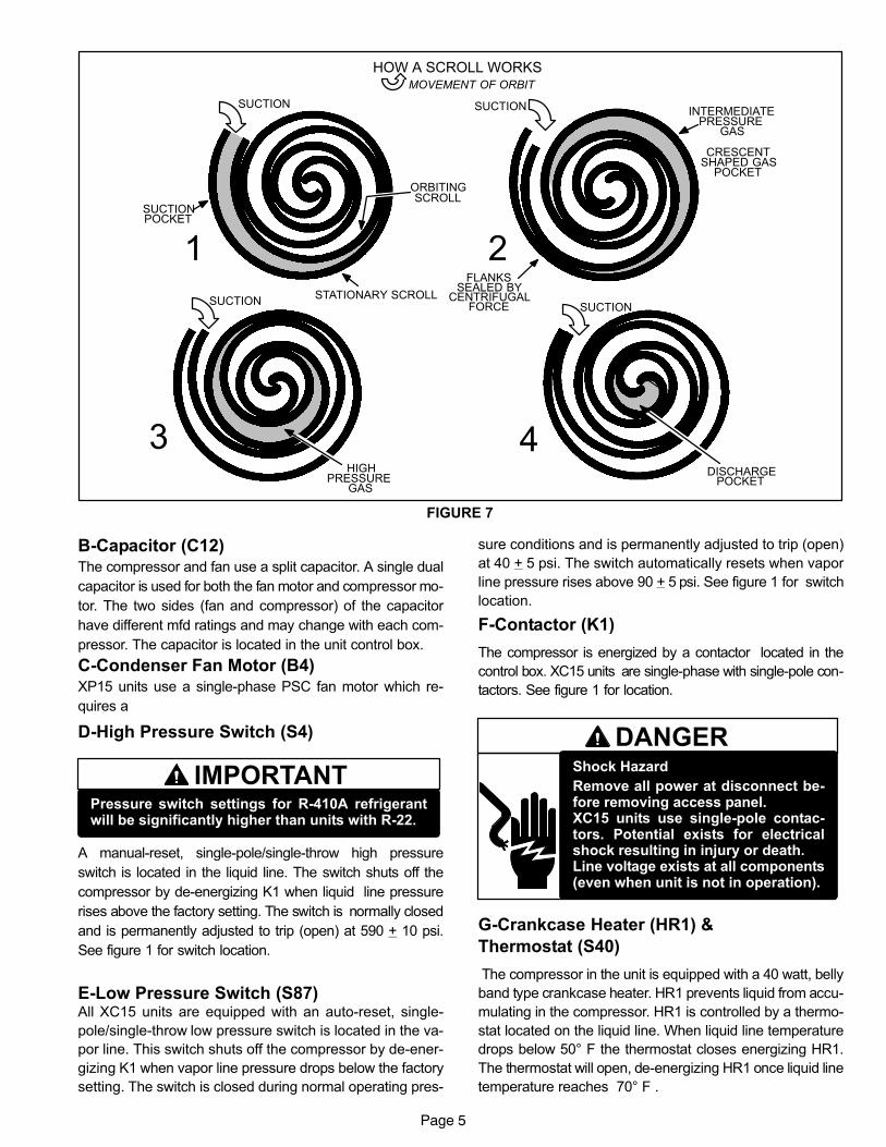
The scroll compressor design is simple, efficient and re-quires few moving parts. A cutaway diagram of the scrollcompressor is shown in figure 4.The scrolls are located inthe top of the compressor can and the motor is located justbelow. The oil level is immediately below the motor.
The scroll is a simple compression concept centeredaround the unique spiral shape of the scroll and its inherentproperties. Figure 5 shows the basic scroll form. Two iden-tical scrolls are mated together forming concentric spiralshapes (figure 6 ). One scroll remains stationary, while theother is allowed to �orbit" (figure 7). Note that the orbitingscroll does not rotate or turn but merely �orbits" the station-ary scroll.
FIGURE 5
SCROLL FORM
FIGURE 6
STATIONARYSCROLL
ORBITING SCROLL
DISCHARGE
SUCTION
CROSS−SECTION OF SCROLLS
TIPS SEALED BYDISCHARGE PRESSURE
DISCHARGEPRESSURE
The counterclockwise orbiting scroll draws gas into the out-
er crescent shaped gas pocket created by the two scrolls
(figure 7− 1). The centrifugal action of the orbiting scroll seals
off the flanks of the scrolls (figure 7− 2). As the orbiting mo-
tion continues, the gas is forced toward the center of the
scroll and the gas pocket becomes compressed (figure 7−3).
When the compressed gas reaches the center, it is dis-
charged vertically into a chamber and discharge port in the
top of the compressor. The discharge pressure forcing down
on the top scroll helps seal off the upper and lower edges
(tips) of the scrolls (figure 6 ). During a single orbit, several
pockets of gas are compressed simultaneously providing
smooth continuous compression.
The scroll compressor is tolerant to the effects of liquid re-
turn. If liquid enters the scrolls, the orbiting scroll is allowed
to separate from the stationary scroll. The liquid is worked
toward the center of the scroll and is discharged. If the com-
pressor is replaced, conventional Lennox cleanup practic-
es must be used.
Due to its efficiency, the scroll compressor is capable of
drawing a much deeper vacuum than reciprocating com-
pressors. Deep vacuum operation can cause internal fusite
arcing resulting in damaged internal parts and will result in
compressor failure. This type of damage can be detected
and will result in denial of warranty claims. The scroll com-
pressor can be used to pump down refrigerant as long as
the pressure is not reduced below 7 psig.
NOTE − During operation, the head of a scroll compressor
may be hot since it is in constant contact with discharge
gas.
The scroll compressors in all XC15 model units are de-
signed for use with R−410A refrigerant and operation at
high pressures. Compressors are shipped from the factory
with 3MA (32MMMA) P.O.E. oil. See electrical section in
this manual for compressor specifications.
Page 5
FIGURE 7
SCROLL
HOW A SCROLL WORKS
SUCTION SUCTION
SUCTION
MOVEMENT OF ORBIT
STATIONARY SCROLL
ORBITING
CRESCENTSHAPED GAS
HIGHPRESSURE
GAS
DISCHARGEPOCKET
FLANKSSEALED BY
CENTRIFUGALFORCE
1 2
3 4
SUCTION
INTERMEDIATEPRESSURE
GAS
SUCTIONPOCKET
B−Capacitor (C12)The compressor and fan use a split capacitor. A single dual
capacitor is used for both the fan motor and compressor mo-
tor. The two sides (fan and compressor) of the capacitor
have different mfd ratings and may change with each com-
pressor. The capacitor is located in the unit control box.
C−Condenser Fan Motor (B4)XP15 units use a single−phase PSC fan motor which re-
quires a
D−High Pressure Switch (S4)
IMPORTANTPressure switch settings for R−410A refrigerantwill be significantly higher than units with R−22.
A manual-reset, single-pole/single-throw high pressure
switch is located in the liquid line. The switch shuts off the
compressor by de−energizing K1 when liquid line pressure
rises above the factory setting. The switch is normally closed
and is permanently adjusted to trip (open) at 590 + 10 psi.
See figure 1 for switch location.
E−Low Pressure Switch (S87)All XC15 units are equipped with an auto-reset, single-
pole/single-throw low pressure switch is located in the va-
por line. This switch shuts off the compressor by de−ener-
gizing K1 when vapor line pressure drops below the factory
setting. The switch is closed during normal operating pres-
sure conditions and is permanently adjusted to trip (open)
at 40 + 5 psi. The switch automatically resets when vapor
line pressure rises above 90 + 5 psi. See figure 1 for switch
location.
F−Contactor (K1)
The compressor is energized by a contactor located in the
control box. XC15 units are single−phase with single−pole con-
tactors. See figure 1 for location.
DANGERShock Hazard
Remove all power at disconnect be-fore removing access panel.XC15 units use single-pole contac-tors. Potential exists for electricalshock resulting in injury or death.Line voltage exists at all components(even when unit is not in operation).
G−Crankcase Heater (HR1) &
Thermostat (S40)
The compressor in the unit is equipped with a 40 watt, belly
band type crankcase heater. HR1 prevents liquid from accu-
mulating in the compressor. HR1 is controlled by a thermo-
stat located on the liquid line. When liquid line temperature
drops below 50° F the thermostat closes energizing HR1.
The thermostat will open, de−energizing HR1 once liquid line
temperature reaches 70° F .

Page 6
H−DrierA filter drier designed for all XC15 model units is factory
installed in the liquid line. The filter drier is designed to re-
move moisture and foreign matter, which can lead to com-
pressor failure.
Moisture and / or Acid Check
Because POE oils absorb moisture, the dryness of the
system must be verified any time the refrigerant sys-
tem is exposed to open air. A compressor oil sample
must be taken to determine if excessive moisture has been
introduced to the oil. Table 1 lists kits available from Lennox
to check POE oils.
If oil sample taken from a system that has been exposed to
open air does not test in the dry color range, the filter drier
MUST be replaced.
IMPORTANTReplacement filter drier MUST be approved forR−410A refrigerant and POE application.
Foreign Matter Check
It is recommended that a liquid line filter drier be replaced
when the pressure drop across the filter drier is greater
than 4 psig.
TABLE 1
KIT CONTENTS TUBE SHELF LIFE
10N46 − Refrigerant Analysis Checkmate−RT700
10N45 − Acid Test Tubes Checkmate−RT750A (three pack)2 − 3 years @ room temperature. 3+years refrigerated
10N44 − Moisture Test TubesCheckmate − RT751 Tubes (threepack)
6 − 12 months @ room temperature. 2years refrigerated
74N40 − Easy Oil Test TubesCheckmate − RT752C Tubes (threepack)
2 − 3 years @ room temperature. 3+years refrigerated
74N39 − Acid Test Kit Sporlan One Shot − TA−1
FIGURE 8
1− Shut off power to unit. Remove access and service panel.
2− Remove high pressure switch from fitting next to filter drier.(A schrader core is located under the high pressure switch).
3− Install high pressure gauge hose onto high pressure switch fitting.Secure service panel back in place
4− Turn power on to unit and turn room thermostat to call for cooling.
5− Record pressure reading on gauge.
6− Remove hose from high pressure fitting and install on liquid line valve.
7− Read liquid line valve pressure.
8− High pressure fitting pressure − liquid line valve pressure = filter drierpressure drop.
9− If pressure drop is greater than 4 psig replace filter drier. See figure 9.
10− Re−install high pressure switch.
MEASURING FILTER DRIER PRESSURE DROP
Note − Service panel must be in place while unit is operational for an acurate pressure drop reading.
FIGURE 9
REPLACING FILTER DRIER
1− Recover all refrigerant from unit.
2− Remove original filter drier.
3− Install new filter drier in existing location or alternate location asshown. Proper brazing procedures should be followed.
4− Evacuate system. See section IV− part B−.
5− Recharge system. See section IV− part C−.
alternate location
Page 7
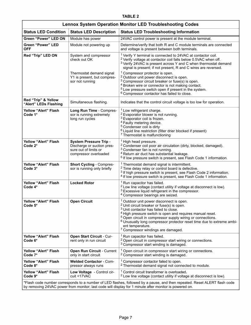
TABLE 2
Lennox System Operation Monitor LED Troubleshooting Codes
Status LED Condition Status LED Description Status LED Troubleshooting Information
Green �Power" LED ON Module has power 24VAC control power is present at the module terminal.
Green �Power" LEDOFF
Module not powering up Determine/verify that both R and C module terminals are connectedand voltage is present between both terminals.
Red �Trip" LED ON System and compressorcheck out OK
1 Verify Y terminal is connected to 24VAC at contactor coil.2 Verify voltage at contactor coil falls below 0.5VAC when off.3 Verify 24VAC is present across Y and C when thermostat demand
signal is present; if not present, R and C wires are reversed.
Thermostat demand signalY1 is present, but compres-sor not running
1 Compressor protector is open.2 Outdoor unit power disconnect is open.3 Compressor circuit breaker or fuse(s) is open.4 Broken wire or connector is not making contact.5 Low pressure switch open if present in the system.6 Compressor contactor has failed to close.
Red �Trip" & Yellow�Alert" LEDs Flashing
Simultaneous flashing. Indicates that the control circuit voltage is too low for operation.
Yellow �Alert" FlashCode 1*
Long Run Time − Compres-sor is running extremelylong run cycles
1 Low refrigerant charge.2 Evaporator blower is not running.3 Evaporator coil is frozen.4 Faulty metering device.5 Condenser coil is dirty.
6 Liquid line restriction (filter drier blocked if present).7 Thermostat is malfunctioning.
Yellow �Alert" FlashCode 2*
System Pressure Trip −Discharge or suction pres-sure out of limits orcompressor overloaded
1 High head pressure.2 Condenser coil poor air circulation (dirty, blocked, damaged).3 Condenser fan is not running.4 Return air duct has substantial leakage.5 If low pressure switch is present, see Flash Code 1 information.
Yellow �Alert" FlashCode 3*
Short Cycling − Compres-sor is running only briefly
1 Thermostat demand signal is intermittent.2 Time delay relay or control board is defective.3 If high pressure switch is present, see Flash Code 2 information.4 If low pressure switch is present, see Flash Code 1 information.
Yellow �Alert" FlashCode 4*
Locked Rotor 1 Run capacitor has failed.2 Low line voltage (contact utility if voltage at disconnect is low).3 Excessive liquid refrigerant in the compressor.4 Compressor bearings are seized.
Yellow �Alert" FlashCode 5*
Open Circuit 1 Outdoor unit power disconnect is open.2 Unit circuit breaker or fuse(s) is open.3 Unit contactor has failed to close.4 High pressure switch is open and requires manual reset.5 Open circuit in compressor supply wiring or connections.6 Unusually long compressor protector reset time due to extreme ambi-
ent temperature.7 Compressor windings are damaged.
Yellow �Alert" FlashCode 6*
Open Start Circuit − Cur-rent only in run circuit
1 Run capacitor has failed.2 Open circuit in compressor start wiring or connections.3 Compressor start winding is damaged.
Yellow �Alert" FlashCode 7*
Open Run Circuit − Currentonly in start circuit
1 Open circuit in compressor start wiring or connections.2 Compressor start winding is damaged.
Yellow �Alert" FlashCode 8*
Welded Contactor − Com-pressor always runs
1 Compressor contactor failed to open.2 Thermostat demand signal not connected to module.
Yellow �Alert" FlashCode 9*
Low Voltage − Control cir-cuit <17VAC
1 Control circuit transformer is overloaded.2 Low line voltage (contact utility if voltage at disconnect is low).
*Flash code number corresponds to a number of LED flashes, followed by a pause, and then repeated. Reset ALERT flash codeby removing 24VAC power from monitor; last code will display for 1 minute after monitor is powered on.
Page 8
I−Lennox System Operation Monitor (A132)
The Lennox system operation monitor (LSOM) is a 24 volt
powered module, (see diagnostic module A132 on wiring
diagram and figure 10) wired directly to the indoor unit. The
LSOM is located in the control box and is used to trouble
shoot problems in the system. The module has three LED’s
for troubleshooting: GREEN indicates power status, YEL-
LOW indicates an abnormal condition and RED indicates
thermostat demand, but compressor not operating. See
table 2 for troubleshooting codes.
The diagnostic indicator detects the most common faultconditions in the air conditioning system. When an abnor-mal condition is detected, the module communicates thespecific condition through its ALERT and TRIP lights. Themodule is capable of detecting both mechanical and elec-trical system problems. See figure 10 for the system opera-tion monitor.
FIGURE 10
Lennox System Operation Monitor
DATA OUTPUTCONNECTOR
.25" SPADECONNECTOR (5)
POWER LED
Y2
Y
L
R
C
ALERT LED
TRIP LED
IMPORTANTThis monitor does not provide safety protection. Themonitor is a monitoring device only and cannot con-trol or shut down other devices.
LED FunctionsAlert LED (green) − Indicates voltage within the range of19−28VAC is present at the system monitor connections.
Alert LED (yellow) − communicates an abnormal systemcondition through a unique Flash Code� the alert LEDflashes a number of times consecutively; then pauses;then repeats the process. This consecutive flashing corre-lates to a particular abnormal condition.
Trip LED (red) − indicates there is a demand signal from thethermostat but no current to the compressor is detected bythe module.
Flash code number − corresponds to a number of LEDflashes, followed by a pause, and then repeated.
Trip & Alert LEDs flashing simultaneously − indicates thatthe control circuit voltage is too low for operation.
Reset ALERT flash code by removing 24VAC power frommonitor. Last ALERT flash code will display for 1 minute af-ter monitor is powered on.
ThermostatThe Lennox system operation monitor (LSOM) requires atwo-stage room thermostat to operate properly.
L terminal connection�The L connection is used to com-municate alert codes to the room thermostat. On se-lected Lennox SignatureStat� thermostats, a blinking�check" LED will display on the room thermostat and onselect White-Rodgers room thermostats, an icon onthe display will flash. Either will flash at the same rateas the LSOM yellow alert LED.
NOTE − ROOM THERMOSTAT WITH SERVICE OR
CHECK LIGHT FEATURE − The room thermostat may
blink the �Check" or �Service" LED or it may come on
solid. Confirm fault by observing and interpreting the
code from the LSOM yellow alert LED at the unit.
Installation verification-LSOM�To verify correct LSOMinstallation, two functional tests can be performed. Dis-connect power from the compressor and force a ther-mostat call for cooling. The red trip LED should turn onindicating a compressor trip as long as 24VAC is mea-sured at the Y terminal. If the red LED does not functionas described, refer to table 2 to verify the wiring. Dis-connect power from the compressor and 24VAC powerfrom LSOM. Remove the wire from the Y terminal ofLSOM and reapply power to the compressor, allowingthe compressor to run. The yellow alert LED will beginflashing a code 8 indicating a welded contactor. Dis-connect power from the compressor and 24VAC powerfrom the LSOM. While the LSOM is off, reattach thewire to the Y terminal. Reapply power to the compres-sor and 24VAC power to the LSOM; the yellow alertLED will flash the previous code 8 for one minute andthen turn off. If the yellow LED does not function as de-scribed, refer to table 2 to verify the wiring.
Resetting alert codes�Alert codes can be reset
manually or automatically:
Manual reset: Cycle the 24VAC power to LSOM off and on.
Automatic reset: After an alert is detected, the LSOM
continues to monitor the compressor and system.
When/if conditions return to normal, the alert code is
turned off automatically.

Page 9
III−REFRIGERANT SYSTEM
WARNINGR−410A refrigerant can be harmful if it is inhaled.R−410A refrigerant must be used and recovered re-sponsibly.
Failure to follow this warning may result in person-al injury or death.
A−Plumbing
Field refrigerant piping consists of liquid and vapor lines
from the outdoor unit (sweat connections) to the indoor coil
(flare or sweat connections). Use Lennox L15 (sweat, non-
flare) series line sets as shown in table 3 or use field-fabri-
cated refrigerant lines. Valve sizes are also listed in table 3.
TABLE 3
XC15
Valve Size
ConnectionsRecommended Line Set
LiquidLine
VaporLine
LiquidLine
VaporLine
L15Line Sets
−024−030−036
3/8 in.
(10 mm)
7/8 in.
(22 mm)3/8 in.
(10 mm)
7/8 in.
(22 mm)
L15−65
15 ft. − 50 ft.(4.6 m − 15 m)
−042 −048
3/8 in.(10 mm)
7/8 in.(22 mm
3/8 in.(10 mm)
7/8 in.(22 mm)
L15−6515 ft. − 50 ft.
(4.6 m − 15 m)
−0603/8 in.
(10 mm)
1−1/8 in.
(29 mm)3/8 in.
(10 mm)
1−1/8 in.
(29 mm)
Field
Fabricated
NOTE − When installing refrigerant lines, refer to Lennox
Technical Support Product Applications for assistance. In
addition, be sure to consider the following points:
Select line set diameters from table 3 to ensure that oil re-turns to the compressor.
Units are designed for line sets of up to fifty feet (15 m); forlonger line sets, consult piping guidelines.
Size vertical vapor riser to maintain minimum velocity atminimum capacity.
B−Service Valves
The liquid line and vapor line service valves (figures 11 and
12) and gauge ports are used for leak testing, evacuating,
charging and checking charge. See table 4 for torque re-
quirements.
Each valve is equipped with a service port which has a fac-
tory−installed Schrader valve. A service port cap protects
the Schrader valve from contamination and serves as the
primary leak seal.
TABLE 4
Part Recommended Torque
Service valve cap 8 ft.− lb. 11 NM
Sheet metal screws 16 in.− lb. 2 NM
Machine screws #10 28 in.− lb. 3 NM
Compressor bolts 90 in.− lb. 10 NM
Gauge port seal cap 8 ft.− lb. 11 NM
To Access Schrader Port:
1 − Remove service port cap with an adjustable wrench.
2 − Connect gauge to the service port.
3 − When testing is complete, replace service port cap.
Tighten finger tight, then an additional 1/6 turn.
To Open Service Valve:
1 − Remove the stem cap with an adjustable wrench.
2 − Use a service wrench with a hex−head extension to
back the stem out counterclockwise as far as it will go.
NOTE − Use a 3/16" hex head extension for 3/8" line
sizes.
3 − Replace the stem cap. Tighten finger tight, then tighten
an additional 1/6 turn.
Page 10
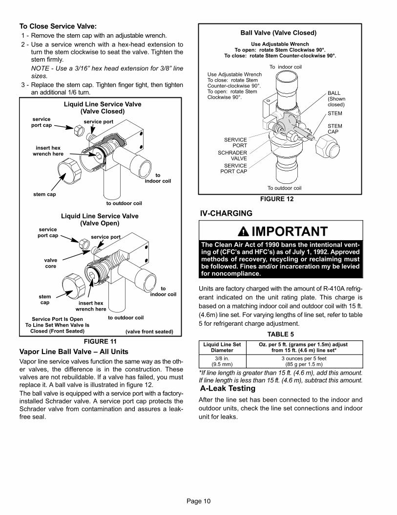
To Close Service Valve:
1 − Remove the stem cap with an adjustable wrench.
2 − Use a service wrench with a hex−head extension toturn the stem clockwise to seat the valve. Tighten thestem firmly.
NOTE − Use a 3/16" hex head extension for 3/8" linesizes.
3 − Replace the stem cap. Tighten finger tight, then tightenan additional 1/6 turn.
Liquid Line Service Valve(Valve Closed)
(valve front seated)
toindoor coil
to outdoor coil
serviceport cap
insert hexwrench here
stem cap
service port
Liquid Line Service Valve(Valve Open)
valvecore
service port
serviceport cap
insert hexwrench here
toindoor coil
to outdoor coil
stemcap
Service Port Is OpenTo Line Set When Valve Is
Closed (Front Seated)
FIGURE 11
Vapor Line Ball Valve – All Units
Vapor line service valves function the same way as the oth-
er valves, the difference is in the construction. These
valves are not rebuildable. If a valve has failed, you must
replace it. A ball valve is illustrated in figure 12.
The ball valve is equipped with a service port with a factory−
installed Schrader valve. A service port cap protects the
Schrader valve from contamination and assures a leak−
free seal.
Ball Valve (Valve Closed)
Use Adjustable WrenchTo open: rotate Stem Clockwise 90°.
To close: rotate Stem Counter-clockwise 90°.
FIGURE 12
BALL(Shownclosed)
STEM
STEMCAP
SERVICEPORT
SCHRADERVALVE
SERVICEPORT CAP
To indoor coil
To outdoor coil
Use Adjustable WrenchTo close: rotate StemCounter-clockwise 90°.To open: rotate StemClockwise 90°.
IV−CHARGING
IMPORTANTThe Clean Air Act of 1990 bans the intentional vent-ing of (CFC’s and HFC’s) as of July 1, 1992. Approvedmethods of recovery, recycling or reclaiming mustbe followed. Fines and/or incarceration my be leviedfor noncompliance.
Units are factory charged with the amount of R−410A refrig-
erant indicated on the unit rating plate. This charge is
based on a matching indoor coil and outdoor coil with 15 ft.
(4.6m) line set. For varying lengths of line set, refer to table
5 for refrigerant charge adjustment.
TABLE 5
Liquid Line SetDiameter
Oz. per 5 ft. (grams per 1.5m) adjust from 15 ft. (4.6 m) line set*
3/8 in.(9.5 mm)
3 ounces per 5 feet(85 g per 1.5 m)
*If line length is greater than 15 ft. (4.6 m), add this amount.If line length is less than 15 ft. (4.6 m), subtract this amount.
A−Leak Testing
After the line set has been connected to the indoor and
outdoor units, check the line set connections and indoor
unit for leaks.

Page 11
WARNINGRefrigerant can be harmful if it is inhaled. Refrigerantmust be used and recovered responsibly.
Failure to follow this warning may result in personalinjury or death.
WARNINGFire, Explosion and Personal SafetyHazard.Failure to follow this warning couldresult in damage, personal injury ordeath.Never use oxygen to pressurize orpurge refrigeration lines. Oxygen,when exposed to a spark or openflame, can cause damage by fireand / or an explosion, that can re-sult in personal injury or death.
WARNINGDanger of explosion!
When using a high pressure gas suchas dry nitrogen to pressurize a refriger-ant or air conditioning system, use aregulator that can control the pressuredown to 1 or 2 psig (6.9 to 13.8 kPa).
Using an Electronic Leak Detector
1 − Connect the high pressure hose of the manifold gauge
set to the vapor valve service port. (Normally, the high
pressure hose is connected to the liquid line port, how-
ever, connecting it to the vapor port helps to protect the
manifold gauge set from damage caused by high pres-
sure.)
2 − With both manifold valves closed, connect the cylinder
of R−410A refrigerant. Open the valve on the R−410A
cylinder (vapor only).
3 − Open the high pressure side of the manifold to allow
R−410A into the line set and indoor unit. Weigh in a
trace amount of R−410A. [A trace amount is a maxi-
mum of 2 ounces (57 g) refrigerant or 3 pounds (31
kPa) pressure.] Close the valve on the R−410A cylinder
and the valve on the high pressure side of the manifold
gauge set. Disconnect R−410A cylinder.
4 − Connect a cylinder of nitrogen with a pressure regulat-
ing valve to the center port of the manifold gauge set.
5 − Adjust nitrogen pressure to 150 psig (1034 kPa). Open
the valve on the high side of the manifold gauge set in
order to pressurize the line set and the indoor coil.
6 − After a few minutes, open a refrigerant port to check
that an adequate amount of refrigerant has been add-
ed for detection (refrigerant requirements will vary
with line lengths). Check all joints for leaks. Purge ni-
trogen and R−410A mixture. Correct any leaks and re-
check.
B−Evacuating the System
Evacuating the system of noncondensables is critical for
proper operation of the unit. Noncondensables are defined
as any gas that will not condense under temperatures and
pressures present during operation of an air conditioning
system. Noncondensables and water vapor combine with
refrigerant to produce substances that corrode copper pip-
ing and compressor parts.
NOTE − This evacuation process is adequate for a new
installation with clean and dry lines. If excessive mois-
ture is present, the evacuation process may be re-
quired more than once.
IMPORTANTUse a thermocouple or thermistor electronic vacuumgauge that is calibrated in microns. Use an instrumentthat reads from 50 microns to at least 10,000 microns.
1 − Connect manifold gauge set to the service valve ports :
� low pressure gauge to vapor line service valve
� high pressure gauge to liquid line service valve
2 − Connect micron gauge.
3 − Connect the vacuum pump (with vacuum gauge) to the
center port of the manifold gauge set.
4 − Open both manifold valves and start the vacuum
pump.
5 − Evacuate the line set and indoor unit to an absolute
pressure of 23,000 microns (29.01 inches of mercu-
ry). During the early stages of evacuation, it is desir-
able to close the manifold gauge valve at least once to
determine if there is a rapid rise in absolute pressure.
A rapid rise in pressure indicates a relatively large leak.
If this occurs, repeat the leak testing procedure.
NOTE − The term absolute pressure means the total
actual pressure within a given volume or system,
above the absolute zero of pressure. Absolute pres-
sure in a vacuum is equal to atmospheric pressure mi-
nus vacuum pressure.
6 − When the absolute pressure reaches 23,000 microns
(29.01 inches of mercury), close the manifold gauge
valves, turn off the vacuum pump and disconnect the
manifold gauge center port hose from vacuum pump.
Attach the manifold center port hose to a nitrogen cylin-
der with pressure regulator set to 150 psig (1034 kPa)
and purge the hose. Open the manifold gauge valves
to break the vacuum in the line set and indoor unit.
Close the manifold gauge valves.

Page 12
CAUTIONDanger of Equipment Damage.Avoid deep vacuum operation. Do not use compres-sors to evacuate a system.Extremely low vacuums can cause internal arcingand compressor failure.Damage caused by deep vacuum operation will voidwarranty.
7 − Shut off the nitrogen cylinder and remove the manifold
gauge hose from the cylinder. Open the manifold
gauge valves to release the nitrogen from the line set
and indoor unit.
8 − Reconnect the manifold gauge to the vacuum pump,
turn the pump on, and continue to evacuate the line set
and indoor unit until the absolute pressure does not
rise above 500 microns (29.9 inches of mercury) within
a 20−minute period after shutting off the vacuum pump
and closing the manifold gauge valves.
9 − When the absolute pressure requirement above has
been met, disconnect the manifold hose from the vacu-
um pump and connect it to an upright cylinder of R−410A
refrigerant. Open the manifold gauge valves to break
the vacuum from 1 to 2 psig positive pressure in the line
set and indoor unit. Close manifold gauge valves and
shut off the R−410A cylinder and remove the manifold
gauge set.
C−Charging
Charge Using Weigh-in Method�Outdoor Temper-
ature < 65ºF (18ºC)
If the system is void of refrigerant, or if the outdoor ambienttemperature is cool, first, locate and repair any leaks andthen weigh in the refrigerant charge into the unit.
1. Recover the refrigerant from the unit.
2. Conduct leak check; evacuate as previously outlined.
3. Weigh in the unit nameplate charge. If weighing facili-ties are not available or if charging the unit during warmweather, use one of the following procedures.
Charge Using the Approach Method�Outdoor
Temp. >65ºF (18ºC)
The following procedure is intended as a general guide andis for use on expansion valve systems only. For best results,outdoor temperature should be 70°F (21°C) to 80°F (26°C).Monitor system pressures while charging.
1. Record outdoor ambient temperature using a digital
thermometer.
2. Attach high pressure gauge set and operate unit for
several minutes to allow system pressures to stabilize.
3. Compare stabilized pressures with those provided in
table 7, �Normal Operating Pressures." Minor varia-
tions in these pressures may be expected due to differ-
ences in installations. Significant differences could
mean that the system is not properly charged or that a
problem exists with some component in the system.
Pressures higher than those listed indicate that the
system is overcharged. Pressures lower than those
listed indicate that the system is undercharged. Con-
tinue to check adjusted charge using approach values.
4. Use the same digital thermometer you used to check
the outdoor ambient temperature to check the liquid
line temperature.
5. The difference between the ambient and liquid temper-
atures should match values given in table 6. If the val-
ues do not agree with the those in table 6, add refriger-
ant to lower the approach temperature, or recover re-
frigerant from the system to increase the approach
temperature.
TABLE 6
XC15 Approach Values
� Liquid Line Temperature
� � Outdoor Temperature
= � Approach Temperature
Model −024 −030 −036 −042 −048 −060
°F(°C)*
10(5.6)
12(6.7)
11(6.1)
13(7.2)
6(3.3)
10(5.6)
NOTE − For best results, use the same electronic thermometer tocheck both outdoor-ambient and liquid-line temperatures.
*F: +/−1.0°; C: +/−0.5°
NOTES −
R−410A refrigerant cylinders are rose−colored. Refrigerant
should be added through the vapor valve in the liquid
state.
Certain R−410A cylinders are identified as being equipped
with a dip tube. These allow liquid refrigerant to be
drawn from the bottom of the cylinder without inverting
the cylinder. DO NOT turn this type cylinder upside−
down to draw refrigerant.

Page 13
TABLE 7
XC15 Normal Operating Pressures In psig (liquid +/− 10 and vapor+/− 5 PSIG)*
Model −024 −030 −036 −042 −048 −060
�F (�C)** Liquid Suction Liquid Suction Liquid Suction Liquid Suction Liquid Suction Liquid Suction
65 (18.3) 239 135 246 135 245 132 260 132 224 129 242 131
70 (21.1) 255 136 266 136 264 133 282 133 241 130 262 132
75 (23.9) 274 137 285 138 285 135 302 134 259 131 282 134
80 (26.7) 293 138 306 139 306 137 325 135 279 133 303 135
85 (29.4) 317 139 328 140 328 137 347 136 301 134 326 136
90 (32.2) 339 140 350 141 352 139 370 137 323 135 349 137
95 (35.0) 362 141 374 142 375 140 395 138 347 137 372 138
100 (37.8) 387 142 399 143 400 141 421 139 372 138 397 140
105 (40.6) 415 144 423 144 425 141 446 141 397 140 422 141
110 (43.3) 440 145 450 145 452 143 475 142 422 141 448 143
115 (46.1) 469 146 477 146 476 144 504 144 449 143 475 146
* These are typical pressures only. Indoor match up, indoor air quality, and indoor load will cause the pressures to vary.
** Temperature of air entering outdoor coil.
Charge Using Subcooling Method�Outdoor Tem-perature > 65ºF (18ºC)
Use the following method to obtain accurate subcoolingvalues. Compare the measured subcooling value to thevalues given in table 8.
Table 8
XC15 Subcooling Values
(psig ) � Saturation Temperature
� � Liquid Line Temperature
= � Subcooling Value
Model −024 −030 −036 −042 −048 −060
°F(°C)*
4(2.2)
4(2.2)
6(3.3)
7(3.9)
6(3.3)
7(3.9)
NOTE − For best results, use the same electronic thermometer tocheck both outdoor-ambient and liquid-line temperatures.
*F: +/−1.0°; C: +/−0.5°
1. With the manifold gauge hose still on the liquid service
port and the unit operating stably, use a digital ther-
mometer to record the liquid line temperature in the
space provided in table 8, and at the same time, record
the liquid line pressure reading in the �(psig___)" space
in the table.
2. Use a temperature/pressure chart for R−410A (table 9)
to determine the saturation temperature for the liquid
line pressure reading and record that in the space pro-
vided in table 8.
3. Subtract the liquid line temperature from the saturation
temperature (according to the chart) to determine the
subcooling value.
4. Compare subcooling value with those in table 8. If sub-
cooling is greater than shown, recover some refriger-
ant; if less than shown, add some refrigerant.
Charge using Subcooling Method�Outdoor Tem-
perature < 65ºF (18ºC)
When the outdoor ambient temperature is below 65°F(18°C), use the subcooling method to charge the unit. Itmay be necessary to restrict the air flow through the out-door coil to achieve pressures in the 325−375 psig(2240−2585 kPa) range. These higher pressures are nec-essary for checking the charge. Block equal sections of airintake panels and move obstructions sideways until the liq-uid pressure is in the 325−375 psig (2240−2585 kPa) range.See figure 13.
Blocking Outdoor Coil
*Outdoor coil should be blocked oneside at a time with cardboard or plasticsheet until proper testing pressures arereached.
cardboard or plastic sheet
*Four−sided unit shown.
FIGURE 13

Page 14
TABLE 9R−410A Temperature/Pressure Chart
R−410A Temperature (°F) − Pressure (Psig)
°F Psig °F Psig °F Psig °F Psig
32 100.8 63 178.5 94 290.8 125 445.9
33 102.9 64 181.6 95 295.1 126 451.8
34 105.0 65 184.3 96 299.4 127 457.6
35 107.1 66 187.7 97 303.8 128 463.5
36 109.2 67 190.9 98 308.2 129 469.5
37 111.4 68 194.1 99 312.7 130 475.6
38 113.6 69 197.3 100 317.2 131 481.6
39 115.8 70 200.6 101 321.8 132 487.8
40 118.0 71 203.9 102 326.4 133 494.0
41 120.3 72 207.2 103 331.0 134 500.2
42 122.6 73 210.6 104 335.7 135 506.5
43 125.0 74 214.0 105 340.5 136 512.9
44 127.3 75 217.4 106 345.3 137 519.3
45 129.7 76 220.9 107 350.1 138 525.8
46 132.2 77 224.4 108 355.0 139 532.4
47 134.6 78 228.0 109 360.0 140 539.0
48 137.1 79 231.6 110 365.0 141 545.6
49 139.6 80 235.3 111 370.0 142 552.3
50 142.2 81 239.0 112 375.1 143 559.1
51 144.8 82 242.7 113 380.2 144 565.9
52 147.4 83 246.5 114 385.4 145 572.8
53 150.1 84 250.3 115 390.7 146 579.8
54 152.8 85 254.1 116 396.0 147 586.8
55 155.5 86 258.0 117 401.3 148 593.8
56 158.2 87 262.0 118 406.7 149 601.0
57 161.0 88 266.0 119 412.2 150 608.1
58 163.9 89 270.0 120 417.7 151 615.4
59 166.7 90 274.1 121 423.2 152 622.7
60 169.6 91 278.2 122 428.8 153 630.1
61 172.6 92 282.3 123 434.5 154 637.5
62 175.4 93 286.5 124 440.2 155 645.0
V−SERVICE AND RECOVERY
WARNINGPolyol ester (POE) oils used with R−410A refriger-ant absorb moisture very quickly. It is very impor-tant that the refrigerant system be kept closed asmuch as possible. DO NOT remove line set caps orservice valve stub caps until you are ready to makeconnections.
IMPORTANTUSE RECOVERY MACHINE RATED FOR R−410AREFRIGERANT.
If the XC15 system must be opened for any kind of service,such as compressor or filter drier replacement, you musttake extra precautions to prevent moisture from enteringthe system. The following steps will help to minimize theamount of moisture that enters the system during recoveryof R−410A. 1 − Use a regulator−equipped nitrogen cylinder to break
the system vacuum. Do not exceed 5 psi. The dry ni-
trogen will fill the system, purging any moisture.
2 − Remove the faulty component and quickly seal the
system (using tape or some other means) to prevent
additional moisture from entering the system.
3 − Do not remove the tape until you are ready to install
new component. Quickly install the replacement com-
ponent.
4 − Evacuate the system to remove any moisture and oth-
er non−condensables.
The XC15 system MUST be checked for moisture any-
time the system is opened.
Any moisture not absorbed by the polyol ester oil can be re-moved by triple evacuation. Moisture that has been ab-sorbed by the compressor oil can be removed by replacingthe filter drier.
IMPORTANTEvacuation of system only will not remove mois-ture from oil. Filter drier must be replaced to elimi-nate moisture from POE oil.

Page 15
VI−SR1 SOUND REDUCTION Figure 14 identifies the sound reduction components and
shows the correct procedure for assembling the sound re-
duction cover.
1. Put SR1 base on unit base pan.
2. Install compressor on base.
3. Cover SR1 base with wet rags to protect againstany brazing material.
4. Braze suction tube.
5. Braze discharge tube.
6. Cool connections to ambient temperature.
7. Perform leak check.
8. Install suction grommet.
9. Install SR1 left and right side covers.
10. Fasten 60" bottom cable tie.
11. Install discharge grommet.
12. Install top caps.
13. Fasten 36" top cable tie.
14. Fasten 36" middle cable tie.
MIDDLE CABLE TIE
BASE
BOTTOM CABLE TIE
SUCTIONGROMMET
LEFTSIDECOVER
RIGHTSIDECOVER
DISCHARGEGROMMET
LEFTTOPCAP
RIGHT TOPCAP
TOP CABLE TIE
FIGURE 14
VII−MAINTENANCE
WARNINGElectric shock hazard. Can cause inju-ry or death. Before attempting to per-form any service or maintenance, turnthe electrical power to unit OFF at dis-connect switch(es). Unit may havemultiple power supplies.
See section II− for removing access panels. Maintenance
and service must be performed by a qualified installer or
service agency. At the beginning of each cooling season,
the system should be checked as follows:
1 − Clean and inspect the outdoor coil. The coil may be
flushed with a water hose. Ensure the power is turned
off before you clean the coil.
2 − Condenser fan motor is prelubricated and sealed. No
further lubrication is needed.
3 − Visually inspect connecting lines and coils for evidence
of oil leaks.
4 − Check wiring for loose connections.
5 − Check for correct voltage at unit (unit operating).
6 − Check amp−draw on condenser fan motor.
NOTE − If owner complains of insufficient cooling, theunit should be gauged and refrigerant chargechecked. Refer to section on refrigerant charging inthis instruction.

Page 16
VIII−DIAGRAMS / OPERATING SEQUENCEA− Unit Diagram XC15−024/060−1P
Sequence of Operation
Cooling Demand
1 Cooling demand initiates at Y1 in the thermostat.
2 Voltage from terminal Y passes through the TOC (if used)
through S4 high pressure switch, energizes K1 compressor
contactor, passes through S87 low pressure switch and re-
turns to common side of the 24VAC power.
3 K1 closes energizing compressor B1 and outdoor fan B4.
Outdoor fan motor is energized.
End of Cooling Demand
4 Cooling demand is satisfied. Terminal Y1 is de−energized.
5 Contactor K1 is de−energized.
6 K1−1 opens, compressor B1 and outdoor fan B4 are de−ener-
gized.