
COPYRIGHT JEPPESEN SANDERSON, INC., 20032005....
23
Enroute Chart Legend - General COPYRIGHT JEPPESEN SANDERSON, INC., 20032005. ALL RIGHTS RESERVED. Revision Date: 20050729 GENERAL Jeppesen Enroute Charts are compiled and constructed using the best available aeronautical and topographical reference charts. Most Jeppesen Enroute Charts use the Lambert Conformal Conic projection. The design is intended primarily for airway instrument navigation to be referenced to cockpit instruments. Charts are identified by code letters for world areas covered by a series, by parenthetical letters for the altitude coverage, and by numbers for the individual chart. For example, P(H/L)2 is a chart of the Pacific series covering both high and low altitude operations and is number 2 of the series. E(HI)3 and E(LO) 10 are charts of the European series covering high and low altitude operations respectively. To use the Low Altitude and High/Low Altitude Enroute Charts, use the small index map on the cover panel to locate the major city closest to your desired area. These names are the major locations shown within each chart panel and are indicated along the “zigdex” at the top of the chart. Open the chart to the panel desired and follow your flight progress by turning the folds like the pages of a book. It is seldom necessary to completely unfold the chart. Although the High Altitude Charts do not have this “zigdex” feature, they may be used in the same way. When the folded chart is opened at one of the zigdex numbers, the exposed portion of the chart is subdivided into four sections by a vertical and a horizontal fold. Each of the sections is labeled at the margin as A, B, C, or D. A combination of the panel number and the lettered section in which it falls is used to simplify finding a location referenced in the Enroute Chart NOTAMS or in the communications tabulation. For example, p5C means you will find the referenced item on panel 5 in section C. Unless otherwise indicated, all bearings and radials are magnetic; enroute distances are in nautical miles; vertical measurements of elevation are in feet above mean sea level; enroute altitudes are either in feet above mean sea level (based on QNH altimeter setting) or clearly expressed as flight levels (FL) (based on standard altimeter setting of 29.92 inches of Mercury or 1013.2 millibars or Hectopascals); and all times are Coordinated Universal Time (UTC) unless labeled local time (LT). Enroute communications are shown on the charts or tabulated on the end folds where they may be referred to with a minimum of paper turning. Terminal communications are also provided in the tabulations except on charts designed solely for high altitude operations. The end panel tabulations refer to the location of the facility on an area chart (if one exists) by a 4-letter identifier, as well as to the location within a panel and section of the Enroute Chart. Due to congestion of airspace information within large metropolitan areas, complete off airway information is not always shown on Enroute Charts. These areas are supplemented by Area Charts at larger chart scales with complete information. They should be used for all flights when arriving or departing an airport within an Area Chart. On the Enroute Charts, the Area Charts are identified by a shaded symbol on the cover panel, and a shaded dashed line, with location name, and Airport identifier on the Enroute Chart. Enroute and Area Charts are supplemented by Enroute Chart NOTAMS when significant changes occur between revision dates. Chart revision dates are always on a Friday (chart completion and/or mailing dates). Following this date a short concise note explains the significant changes made. Chart EFFECTIVE dates other than EFFECTIVE UPON RECEIPT are provided when significant changes have been charted which will become effective on the date indicated. Chart symbols are portrayed on the following pages with an explanation of their use. Reference should be made to the Chart Glossary for a more complete explanation of terms. This legend covers all Enroute and Area Charts. Chart symbols on the following pages may not appear on each chart. JEPPESEN IFR ENROUTE PLOTTER INSTRUCTIONS — ENROUTE AND AREA CHARTS MILEAGES Most Enroute and Area Chart mileages are represented on the plotter. Check the top margin of the chart in use for the correct scale. All chart scales, and all plotter scales, are in nautical miles. BEARINGS AND COURSES The plotter centerline is highlighted by arrows from each compass rose. Position the plotter centerline over the desired track to be flown. Slide the plotter left or right along the track until one of the compass roses is centered over the desired navaid. If the centerline arrow on the compass rose points in the SAME direction as your flight, read the radial or bearing at the north tick extending from the navaid. If the centerline arrow on the compass rose points OPPOSITE to the direction of flight, the radial or bearing is the reciprocal of the number read at the navaid’s north magnetic tick. NOTE: If your earlier version plotter does not depict the arrows be sure the plotter is positioned so that the 360° position on the compass rose points in the SAME direction as your flight. The compass rose is read in a counter-clockwise direction. Example: COPYRIGHT JEPPESEN SANDERSON, INC., 20032005. ALL RIGHTS RESERVED.
Transcript of COPYRIGHT JEPPESEN SANDERSON, INC., 20032005....
Enroute Chart Legend - General
COPYRIGHT JEPPESEN SANDERSON, INC., 20032005. ALL RIGHTS RESERVED.
Revision Date: 20050729
GENERAL
Jeppesen Enroute Charts are compiled and constructed using the best available aeronautical and topographical reference charts.
Most Jeppesen Enroute Charts use the Lambert Conformal Conic projection. The design is intended primarily for airway
instrument navigation to be referenced to cockpit instruments.
Charts are identified by code letters for world areas covered by a series, by parenthetical letters for the altitude coverage, and
by numbers for the individual chart. For example, P(H/L)2 is a chart of the Pacific series covering both high and low altitude
operations and is number 2 of the series. E(HI)3 and E(LO) 10 are charts of the European series covering high and low altitude
operations respectively.
To use the Low Altitude and High/Low Altitude Enroute Charts, use the small index map on the cover panel to locate the major
city closest to your desired area. These names are the major locations shown within each chart panel and are indicated along
the “zigdex” at the top of the chart. Open the chart to the panel desired and follow your flight progress by turning the folds like
the pages of a book. It is seldom necessary to completely unfold the chart. Although the High Altitude Charts do not have this
“zigdex” feature, they may be used in the same way.
When the folded chart is opened at one of the zigdex numbers, the exposed portion of the chart is subdivided into four sections
by a vertical and a horizontal fold. Each of the sections is labeled at the margin as A, B, C, or D. A combination of the panel
number and the lettered section in which it falls is used to simplify finding a location referenced in the Enroute Chart NOTAMS or
in the communications tabulation. For example, p5C means you will find the referenced item on panel 5 in section C.
Unless otherwise indicated, all bearings and radials are magnetic; enroute distances are in nautical miles; vertical measurements
of elevation are in feet above mean sea level; enroute altitudes are either in feet above mean sea level (based on QNH altimeter
setting) or clearly expressed as flight levels (FL) (based on standard altimeter setting of 29.92 inches of Mercury or 1013.2
millibars or Hectopascals); and all times are Coordinated Universal Time (UTC) unless labeled local time (LT).
Enroute communications are shown on the charts or tabulated on the end folds where they may be referred to with a minimum
of paper turning. Terminal communications are also provided in the tabulations except on charts designed solely for high altitude
operations. The end panel tabulations refer to the location of the facility on an area chart (if one exists) by a 4-letter identifier,
as well as to the location within a panel and section of the Enroute Chart.
Due to congestion of airspace information within large metropolitan areas, complete off airway information is not always shown
on Enroute Charts. These areas are supplemented by Area Charts at larger chart scales with complete information. They should
be used for all flights when arriving or departing an airport within an Area Chart.
On the Enroute Charts, the Area Charts are identified by a shaded symbol on the cover panel, and a shaded dashed line, with
location name, and Airport identifier on the Enroute Chart.
Enroute and Area Charts are supplemented by Enroute Chart NOTAMS when significant changes occur between revision dates.
Chart revision dates are always on a Friday (chart completion and/or mailing dates). Following this date a short concise note
explains the significant changes made.
Chart EFFECTIVE dates other than EFFECTIVE UPON RECEIPT are provided when significant changes have been charted which
will become effective on the date indicated.
Chart symbols are portrayed on the following pages with an explanation of their use. Reference should be made to the Chart
Glossary for a more complete explanation of terms. This legend covers all Enroute and Area Charts. Chart symbols on the
following pages may not appear on each chart.
JEPPESEN IFR ENROUTE PLOTTER INSTRUCTIONS — ENROUTE AND AREA CHARTS
MILEAGES
Most Enroute and Area Chart mileages are represented on the plotter. Check the top margin of the chart in use for the correct
scale. All chart scales, and all plotter scales, are in nautical miles.
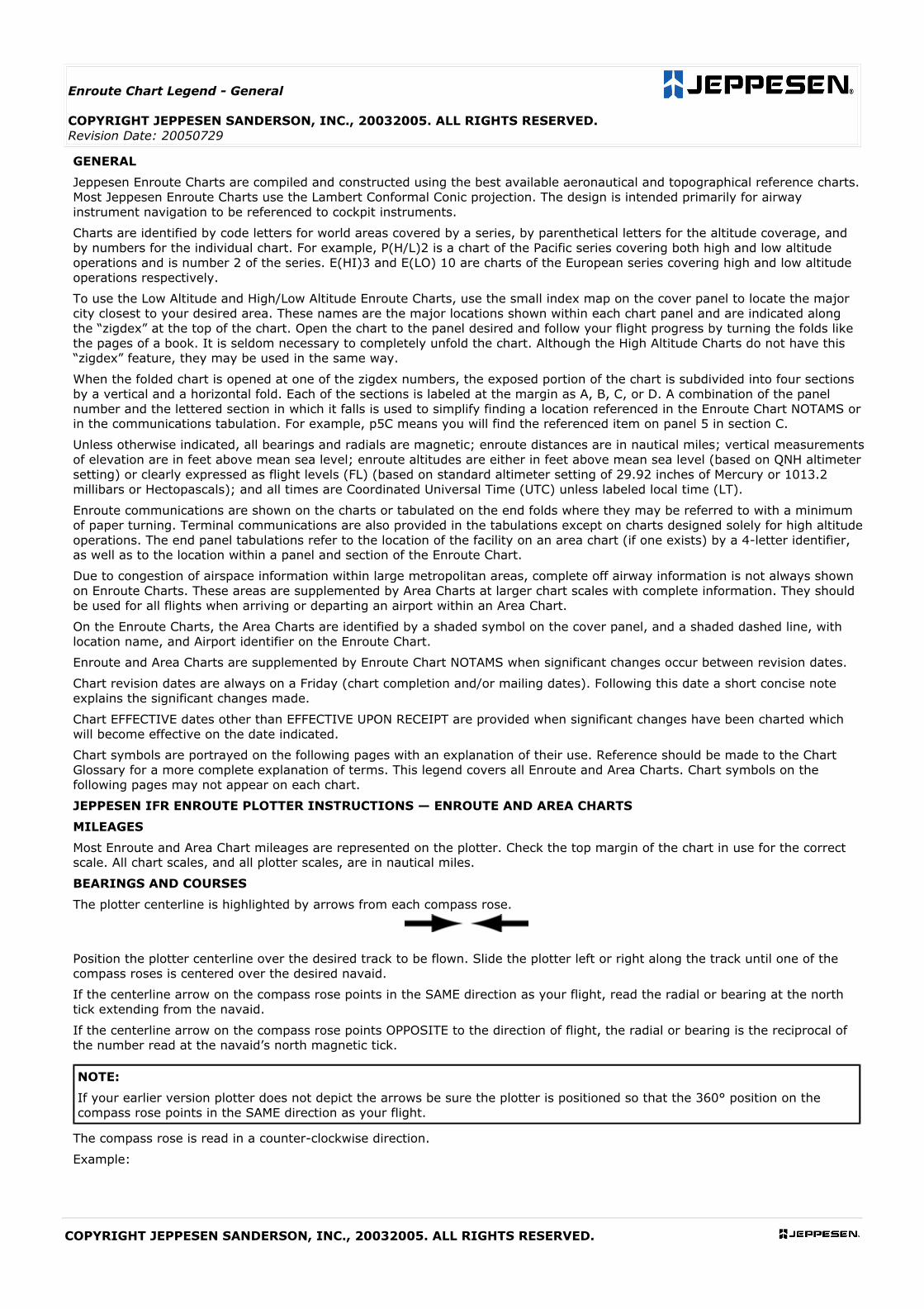
BEARINGS AND COURSES
The plotter centerline is highlighted by arrows from each compass rose.
Position the plotter centerline over the desired track to be flown. Slide the plotter left or right along the track until one of the
compass roses is centered over the desired navaid.
If the centerline arrow on the compass rose points in the SAME direction as your flight, read the radial or bearing at the north
tick extending from the navaid.
If the centerline arrow on the compass rose points OPPOSITE to the direction of flight, the radial or bearing is the reciprocal of
the number read at the navaid’s north magnetic tick.
NOTE:
If your earlier version plotter does not depict the arrows be sure the plotter is positioned so that the 360° position on the
compass rose points in the SAME direction as your flight.
The compass rose is read in a counter-clockwise direction.
Example:
COPYRIGHT JEPPESEN SANDERSON, INC., 20032005. ALL RIGHTS RESERVED.
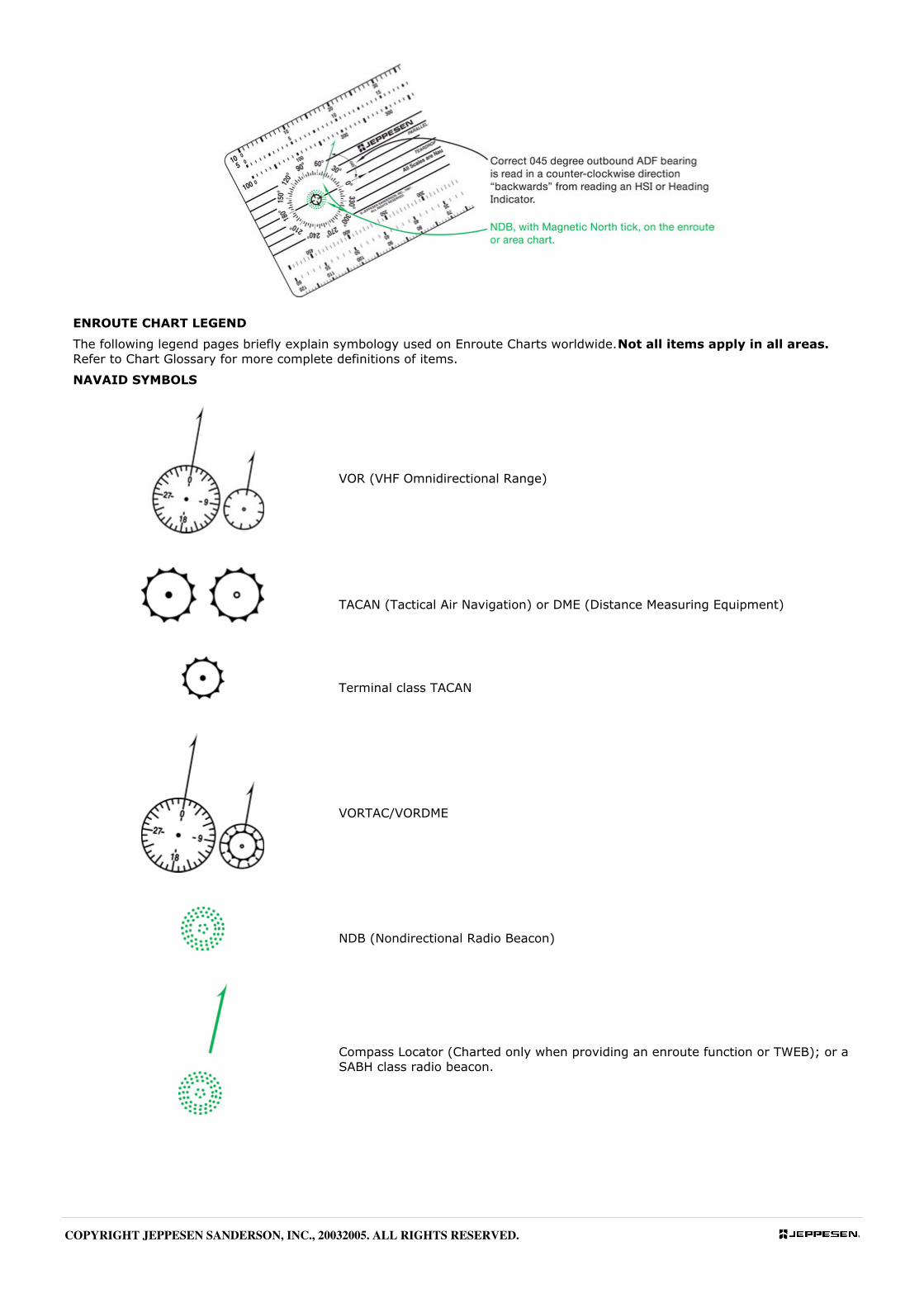
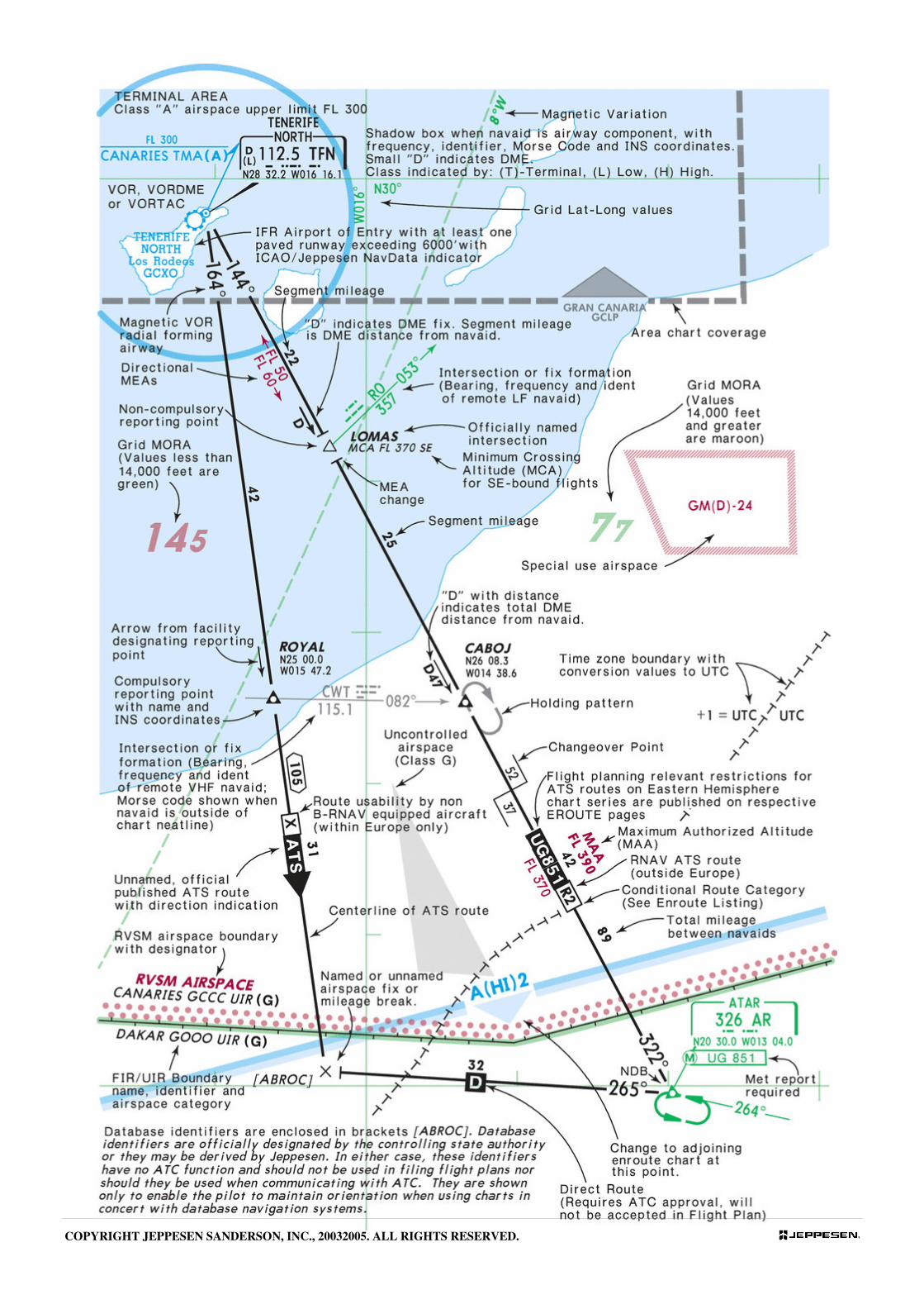
ENROUTE CHART LEGEND
The following legend pages briefly explain symbology used on Enroute Charts worldwide. Not all items apply in all areas.
Refer to Chart Glossary for more complete definitions of items.
NAVAID SYMBOLS
VOR (VHF Omnidirectional Range)
TACAN (Tactical Air Navigation) or DME (Distance Measuring Equipment)
Terminal class TACAN
VORTAC/VORDME
NDB (Nondirectional Radio Beacon)
Compass Locator (Charted only when providing an enroute function or TWEB); or a
SABH class radio beacon.
COPYRIGHT JEPPESEN SANDERSON, INC., 20032005. ALL RIGHTS RESERVED.
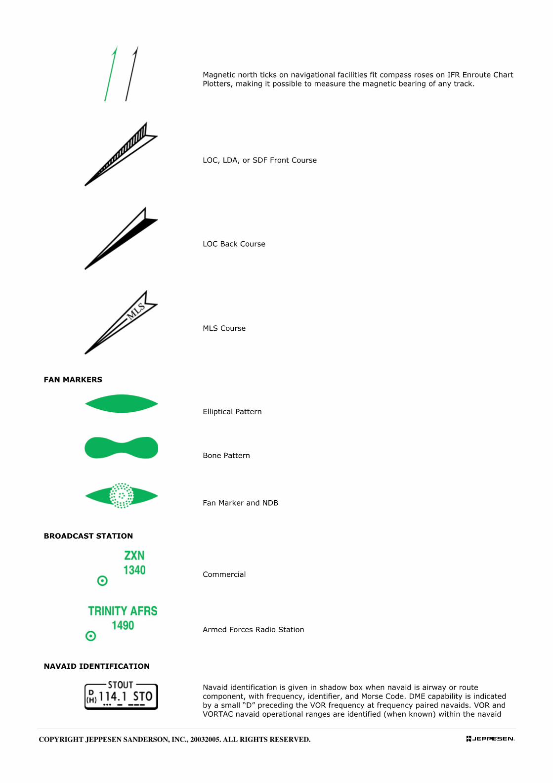
Magnetic north ticks on navigational facilities fit compass roses on IFR Enroute Chart
Plotters, making it possible to measure the magnetic bearing of any track.
LOC, LDA, or SDF Front Course
LOC Back Course
MLS Course
FAN MARKERS
Elliptical Pattern
Bone Pattern
Fan Marker and NDB
BROADCAST STATION
Commercial
Armed Forces Radio Station
NAVAID IDENTIFICATION
Navaid identification is given in shadow box when navaid is airway or route
component, with frequency, identifier, and Morse Code. DME capability is indicated
by a small “D” preceding the VOR frequency at frequency paired navaids. VOR and
VORTAC navaid operational ranges are identified (when known) within the navaid
COPYRIGHT JEPPESEN SANDERSON, INC., 20032005. ALL RIGHTS RESERVED.
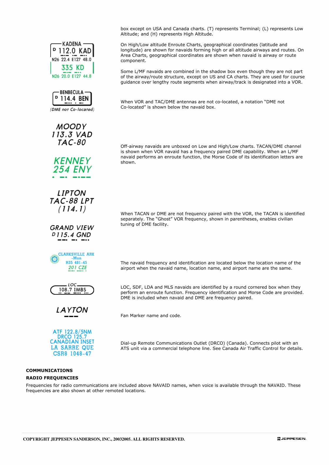
box except on USA and Canada charts. (T) represents Terminal; (L) represents Low
Altitude; and (H) represents High Altitude.
On High/Low altitude Enroute Charts, geographical coordinates (latitude and
longitude) are shown for navaids forming high or all altitude airways and routes. On
Area Charts, geographical coordinates are shown when navaid is airway or route
component.
Some L/MF navaids are combined in the shadow box even though they are not part
of the airway/route structure, except on US and CA charts. They are used for course
guidance over lengthy route segments when airway/track is designated into a VOR.
When VOR and TAC/DME antennas are not co-located, a notation “DME not
Co-located” is shown below the navaid box.
Off-airway navaids are unboxed on Low and High/Low charts. TACAN/DME channel
is shown when VOR navaid has a frequency paired DME capability. When an L/MF
navaid performs an enroute function, the Morse Code of its identification letters are
shown.
When TACAN or DME are not frequency paired with the VOR, the TACAN is identified
separately. The “Ghost” VOR frequency, shown in parentheses, enables civilian
tuning of DME facility.
The navaid frequency and identification are located below the location name of the
airport when the navaid name, location name, and airport name are the same.
LOC, SDF, LDA and MLS navaids are identified by a round cornered box when they
perform an enroute function. Frequency identification and Morse Code are provided.
DME is included when navaid and DME are frequency paired.
Fan Marker name and code.
Dial-up Remote Communications Outlet (DRCO) (Canada). Connects pilot with an
ATS unit via a commercial telephone line. See Canada Air Traffic Control for details.
COMMUNICATIONS
RADIO FREQUENCIES
Frequencies for radio communications are included above NAVAID names, when voice is available through the NAVAID. These
frequencies are also shown at other remoted locations.
COPYRIGHT JEPPESEN SANDERSON, INC., 20032005. ALL RIGHTS RESERVED.
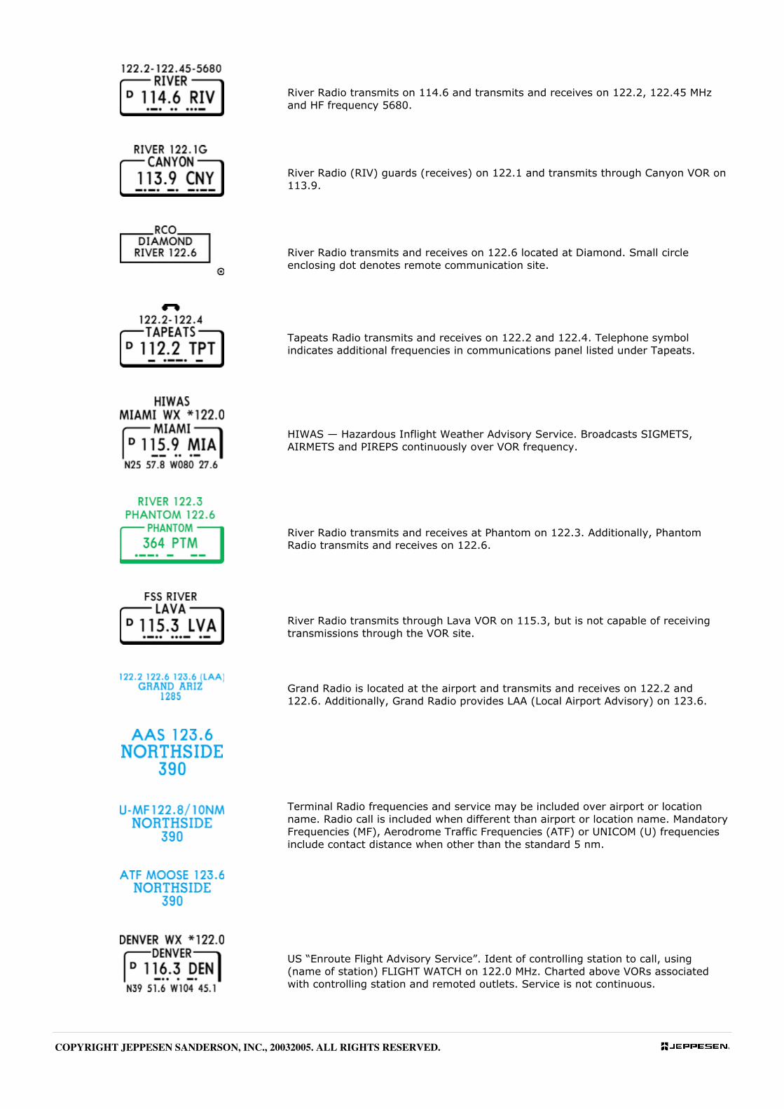
River Radio transmits on 114.6 and transmits and receives on 122.2, 122.45 MHz
and HF frequency 5680.
River Radio (RIV) guards (receives) on 122.1 and transmits through Canyon VOR on
113.9.
River Radio transmits and receives on 122.6 located at Diamond. Small circle
enclosing dot denotes remote communication site.
Tapeats Radio transmits and receives on 122.2 and 122.4. Telephone symbol
indicates additional frequencies in communications panel listed under Tapeats.
HIWAS — Hazardous Inflight Weather Advisory Service. Broadcasts SIGMETS,
AIRMETS and PIREPS continuously over VOR frequency.
River Radio transmits and receives at Phantom on 122.3. Additionally, Phantom
Radio transmits and receives on 122.6.
River Radio transmits through Lava VOR on 115.3, but is not capable of receiving
transmissions through the VOR site.
Grand Radio is located at the airport and transmits and receives on 122.2 and
122.6. Additionally, Grand Radio provides LAA (Local Airport Advisory) on 123.6.
Terminal Radio frequencies and service may be included over airport or location
name. Radio call is included when different than airport or location name. Mandatory
Frequencies (MF), Aerodrome Traffic Frequencies (ATF) or UNICOM (U) frequencies
include contact distance when other than the standard 5 nm.
US “Enroute Flight Advisory Service”. Ident of controlling station to call, using
(name of station) FLIGHT WATCH on 122.0 MHz. Charted above VORs associated
with controlling station and remoted outlets. Service is not continuous.
COPYRIGHT JEPPESEN SANDERSON, INC., 20032005. ALL RIGHTS RESERVED.
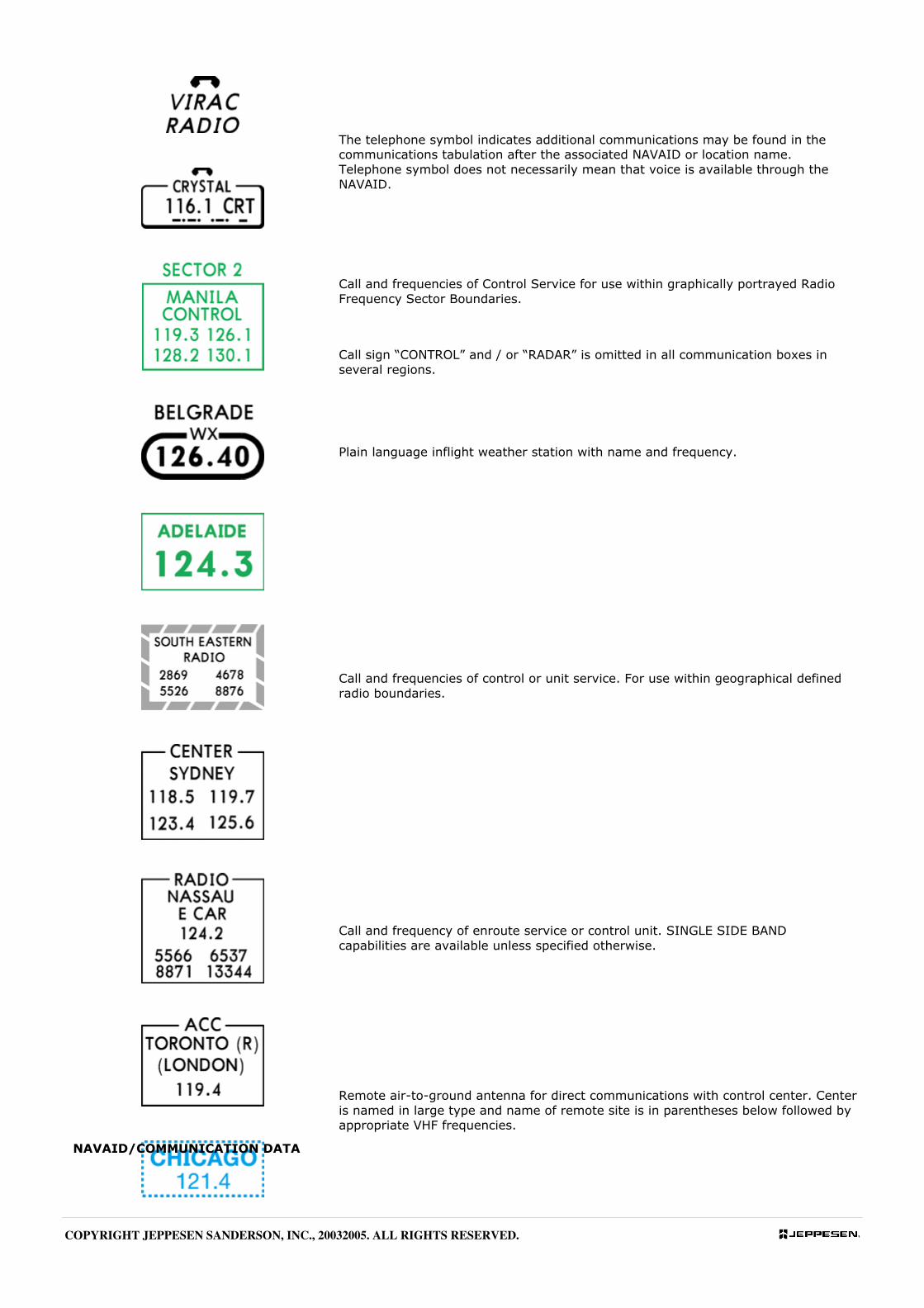
The telephone symbol indicates additional communications may be found in the
communications tabulation after the associated NAVAID or location name.
Telephone symbol does not necessarily mean that voice is available through the
NAVAID.
Call and frequencies of Control Service for use within graphically portrayed Radio
Frequency Sector Boundaries.
Call sign “CONTROL” and / or “RADAR” is omitted in all communication boxes in
several regions.
Plain language inflight weather station with name and frequency.
Call and frequencies of control or unit service. For use within geographical defined
radio boundaries.
Call and frequency of enroute service or control unit. SINGLE SIDE BAND
capabilities are available unless specified otherwise.
Remote air-to-ground antenna for direct communications with control center. Center
is named in large type and name of remote site is in parentheses below followed by
appropriate VHF frequencies.
NAVAID/COMMUNICATION DATA
COPYRIGHT JEPPESEN SANDERSON, INC., 20032005. ALL RIGHTS RESERVED.
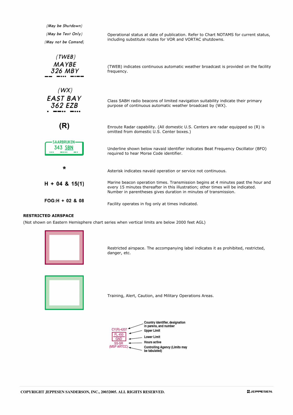
Operational status at date of publication. Refer to Chart NOTAMS for current status,
including substitute routes for VOR and VORTAC shutdowns.
(TWEB) indicates continuous automatic weather broadcast is provided on the facility
frequency.
Class SABH radio beacons of limited navigation suitability indicate their primary
purpose of continuous automatic weather broadcast by (WX).
Enroute Radar capability. (All domestic U.S. Centers are radar equipped so (R) is
omitted from domestic U.S. Center boxes.)
Underline shown below navaid identifier indicates Beat Frequency Oscillator (BFO)
required to hear Morse Code identifier.
Asterisk indicates navaid operation or service not continuous.
Marine beacon operation times. Transmission begins at 4 minutes past the hour and
every 15 minutes thereafter in this illustration; other times will be indicated.
Number in parentheses gives duration in minutes of transmission.
Facility operates in fog only at times indicated.
RESTRICTED AIRSPACE
(Not shown on Eastern Hemisphere chart series when vertical limits are below 2000 feet AGL)
Restricted airspace. The accompanying label indicates it as prohibited, restricted,
danger, etc.
Training, Alert, Caution, and Military Operations Areas.
COPYRIGHT JEPPESEN SANDERSON, INC., 20032005. ALL RIGHTS RESERVED.
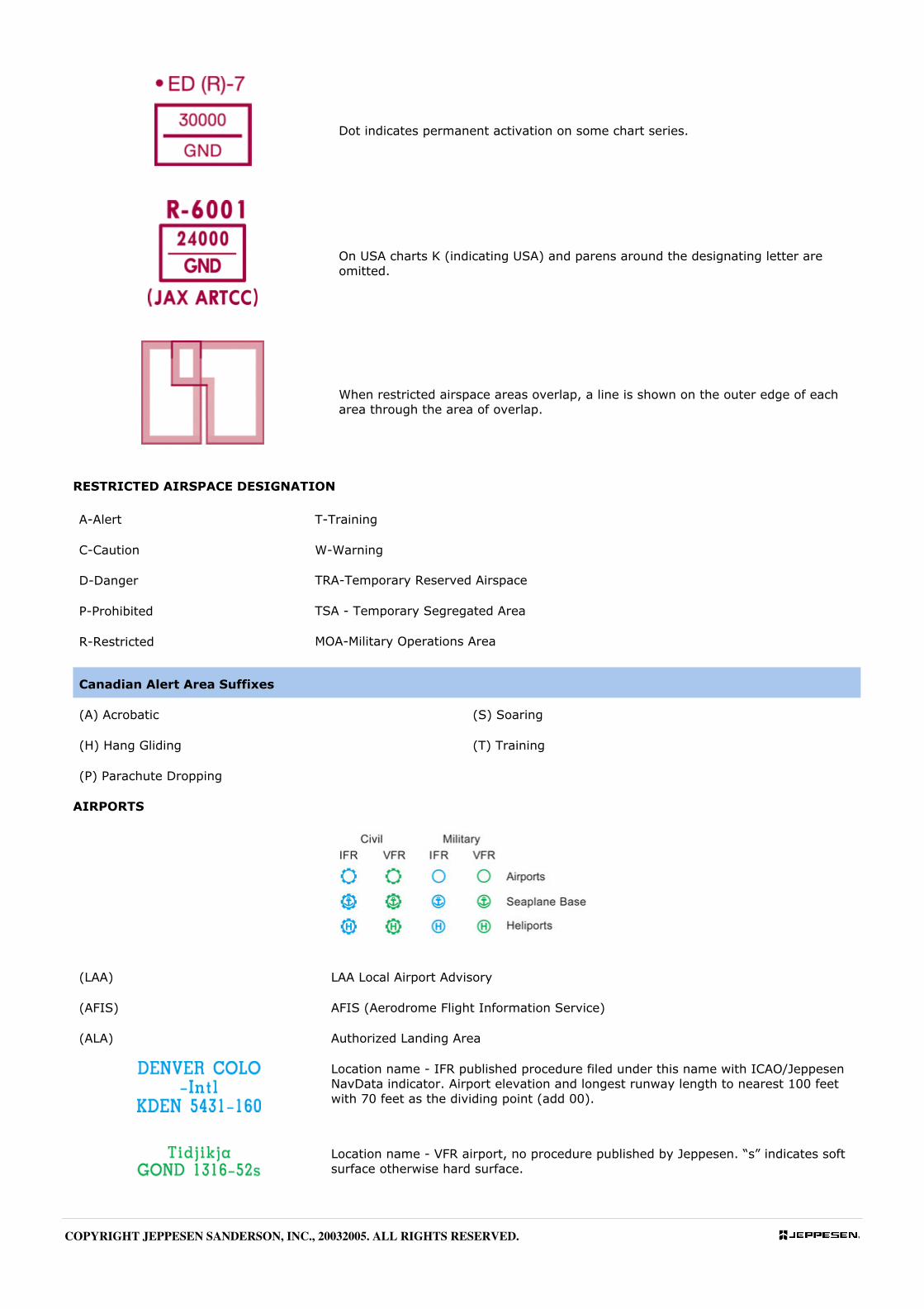
Dot indicates permanent activation on some chart series.
On USA charts K (indicating USA) and parens around the designating letter are
omitted.
When restricted airspace areas overlap, a line is shown on the outer edge of each
area through the area of overlap.
RESTRICTED AIRSPACE DESIGNATION
A-Alert T-Training
C-Caution W-Warning
D-Danger TRA-Temporary Reserved Airspace
P-Prohibited TSA - Temporary Segregated Area
R-Restricted MOA-Military Operations Area
Canadian Alert Area Suffixes
(A) Acrobatic (S) Soaring
(H) Hang Gliding (T) Training
(P) Parachute Dropping
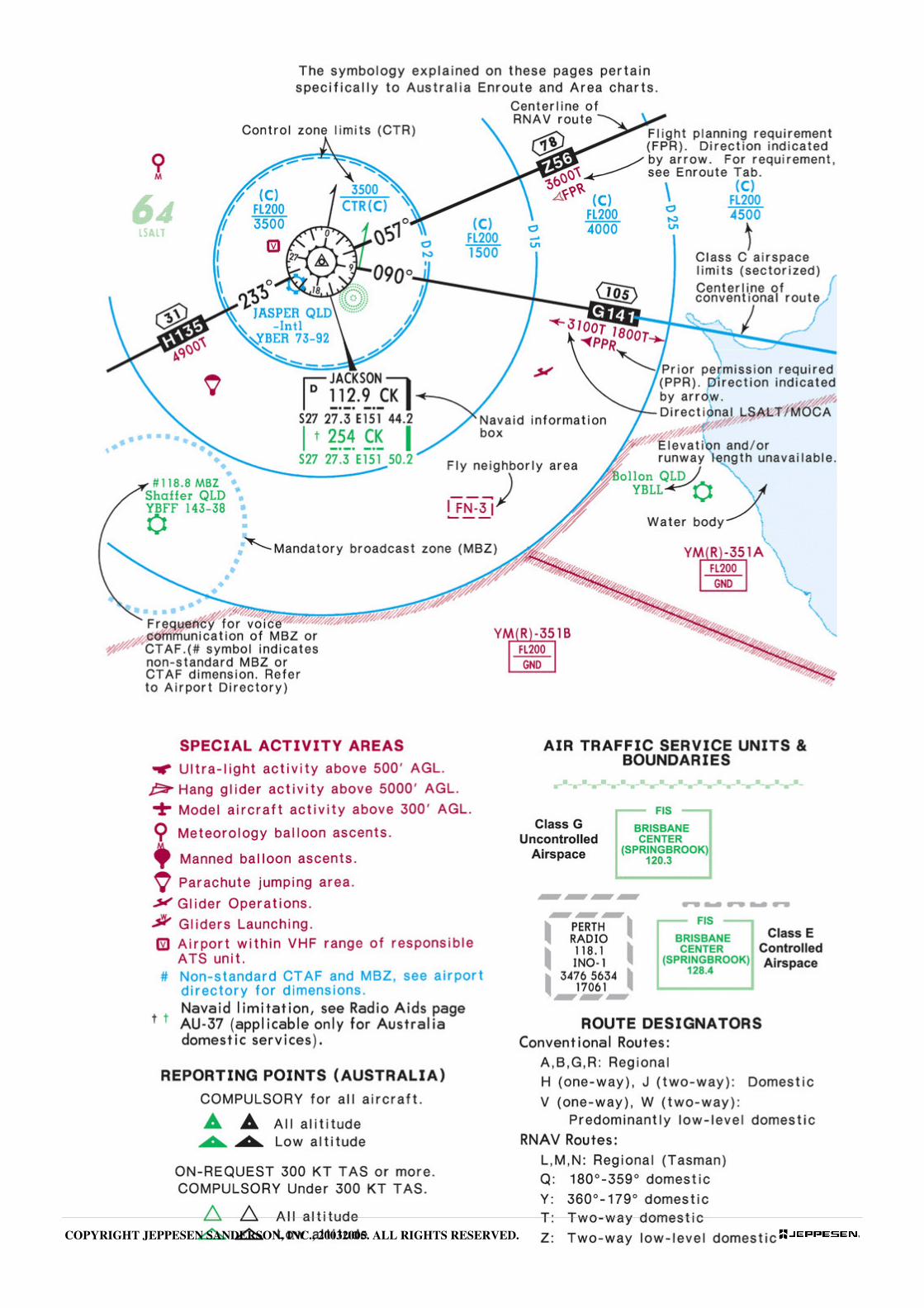
AIRPORTS
(LAA) LAA Local Airport Advisory
(AFIS) AFIS (Aerodrome Flight Information Service)
(ALA) Authorized Landing Area
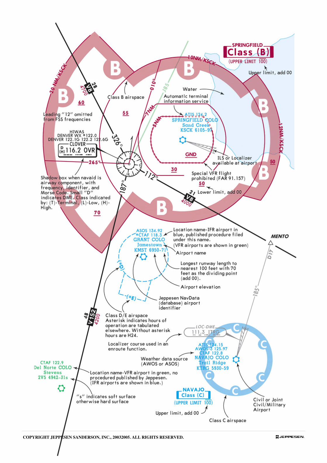
Location name - IFR published procedure filed under this name with ICAO/Jeppesen
NavData indicator. Airport elevation and longest runway length to nearest 100 feet
with 70 feet as the dividing point (add 00).
Location name - VFR airport, no procedure published by Jeppesen. “s” indicates soft
surface otherwise hard surface.
COPYRIGHT JEPPESEN SANDERSON, INC., 20032005. ALL RIGHTS RESERVED.
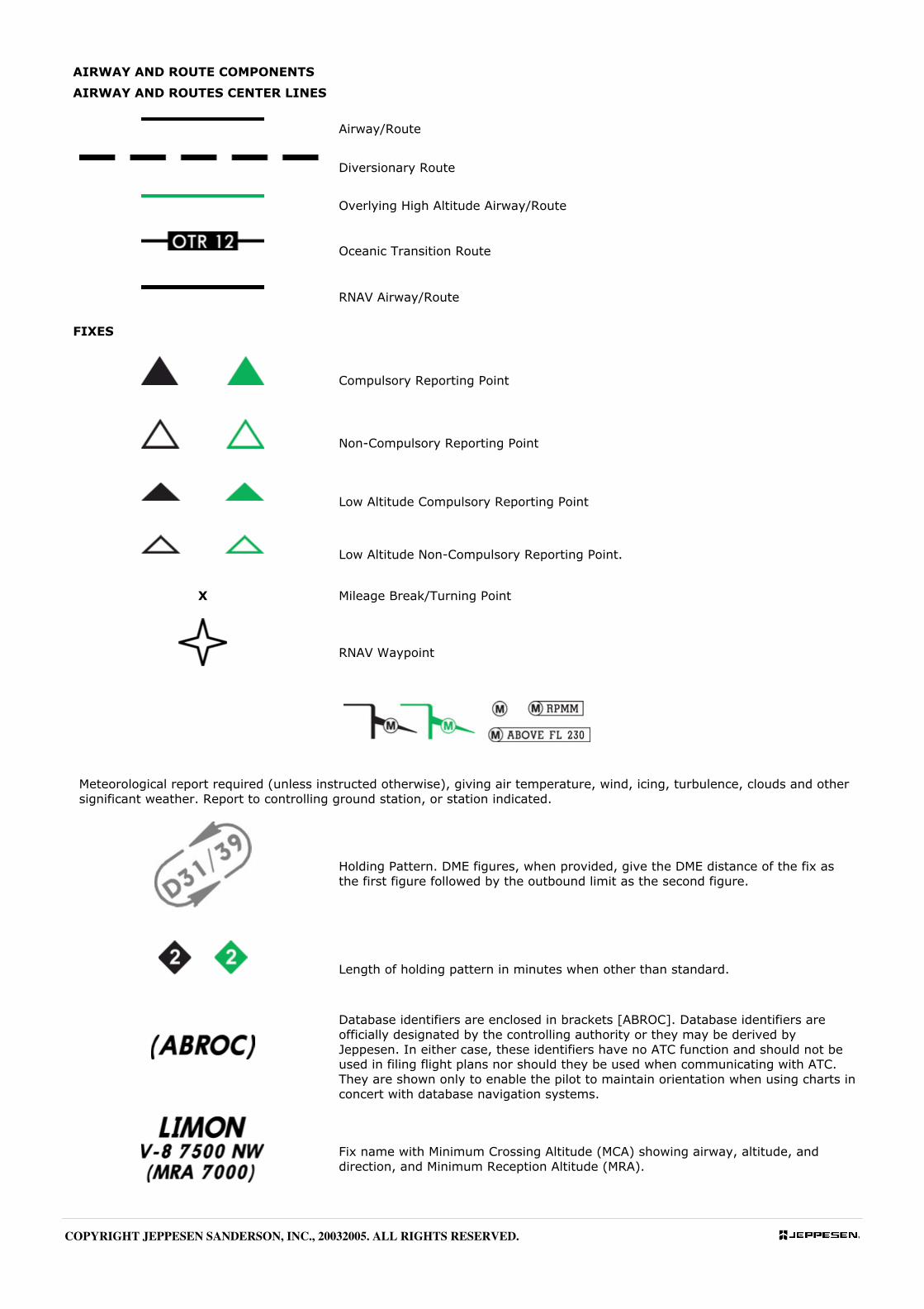
AIRWAY AND ROUTE COMPONENTS
AIRWAY AND ROUTES CENTER LINES
Airway/Route
Diversionary Route
Overlying High Altitude Airway/Route
Oceanic Transition Route
RNAV Airway/Route
FIXES
Compulsory Reporting Point
Non-Compulsory Reporting Point
Low Altitude Compulsory Reporting Point
Low Altitude Non-Compulsory Reporting Point.
X Mileage Break/Turning Point
RNAV Waypoint
Meteorological report required (unless instructed otherwise), giving air temperature, wind, icing, turbulence, clouds and other
significant weather. Report to controlling ground station, or station indicated.
Holding Pattern. DME figures, when provided, give the DME distance of the fix as
the first figure followed by the outbound limit as the second figure.
Length of holding pattern in minutes when other than standard.
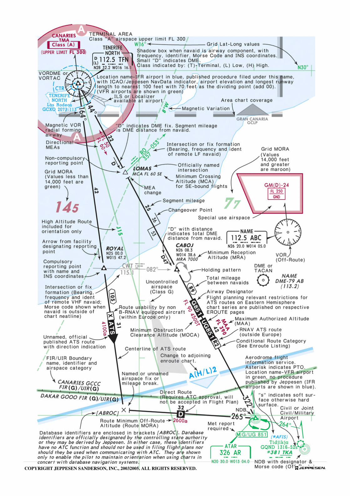
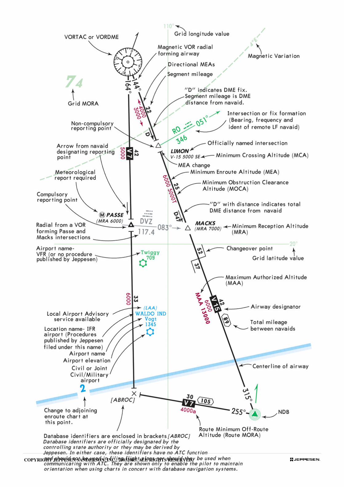
Database identifiers are enclosed in brackets [ABROC]. Database identifiers are
officially designated by the controlling authority or they may be derived by
Jeppesen. In either case, these identifiers have no ATC function and should not be
used in filing flight plans nor should they be used when communicating with ATC.
They are shown only to enable the pilot to maintain orientation when using charts in
concert with database navigation systems.
Fix name with Minimum Crossing Altitude (MCA) showing airway, altitude, and
direction, and Minimum Reception Altitude (MRA).
COPYRIGHT JEPPESEN SANDERSON, INC., 20032005. ALL RIGHTS RESERVED.
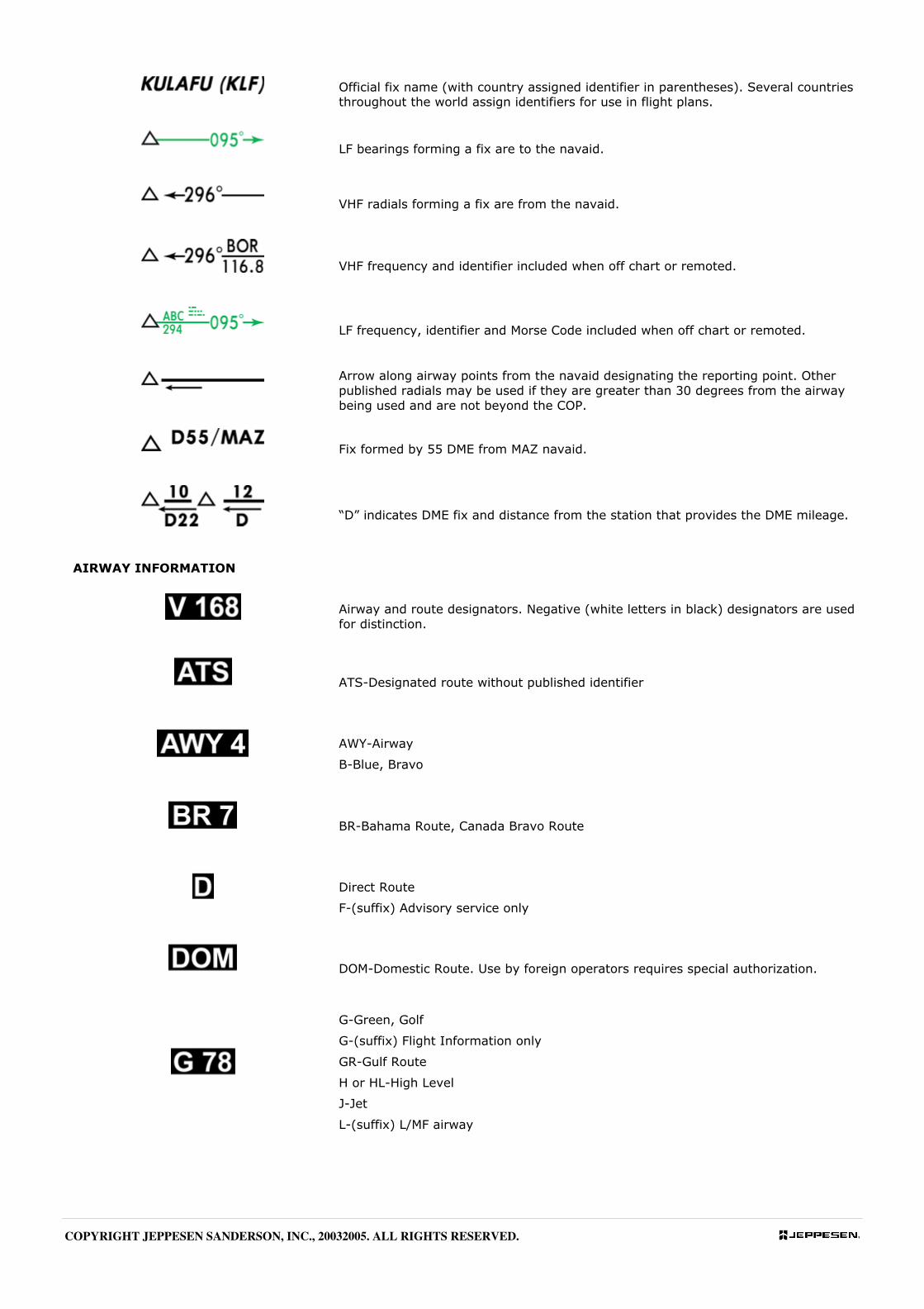
Official fix name (with country assigned identifier in parentheses). Several countries
throughout the world assign identifiers for use in flight plans.
LF bearings forming a fix are to the navaid.
VHF radials forming a fix are from the navaid.
VHF frequency and identifier included when off chart or remoted.
LF frequency, identifier and Morse Code included when off chart or remoted.
Arrow along airway points from the navaid designating the reporting point. Other
published radials may be used if they are greater than 30 degrees from the airway
being used and are not beyond the COP.
Fix formed by 55 DME from MAZ navaid.
“D” indicates DME fix and distance from the station that provides the DME mileage.
AIRWAY INFORMATION
Airway and route designators. Negative (white letters in black) designators are used
for distinction.
ATS-Designated route without published identifier
AWY-Airway
B-Blue, Bravo
BR-Bahama Route, Canada Bravo Route
Direct Route
F-(suffix) Advisory service only
DOM-Domestic Route. Use by foreign operators requires special authorization.
G-Green, Golf
G-(suffix) Flight Information only
GR-Gulf Route
H or HL-High Level
J-Jet
L-(suffix) L/MF airway
COPYRIGHT JEPPESEN SANDERSON, INC., 20032005. ALL RIGHTS RESERVED.
COPYRIGHT JEPPESEN SANDERSON, INC., 20032005. ALL RIGHTS RESERVED.

COPYRIGHT JEPPESEN SANDERSON, INC., 20032005. ALL RIGHTS RESERVED.
COPYRIGHT JEPPESEN SANDERSON, INC., 20032005. ALL RIGHTS RESERVED.

COPYRIGHT JEPPESEN SANDERSON, INC., 20032005. ALL RIGHTS RESERVED.
COPYRIGHT JEPPESEN SANDERSON, INC., 20032005. ALL RIGHTS RESERVED.

COPYRIGHT JEPPESEN SANDERSON, INC., 20032005. ALL RIGHTS RESERVED.
COPYRIGHT JEPPESEN SANDERSON, INC., 20032005. ALL RIGHTS RESERVED.
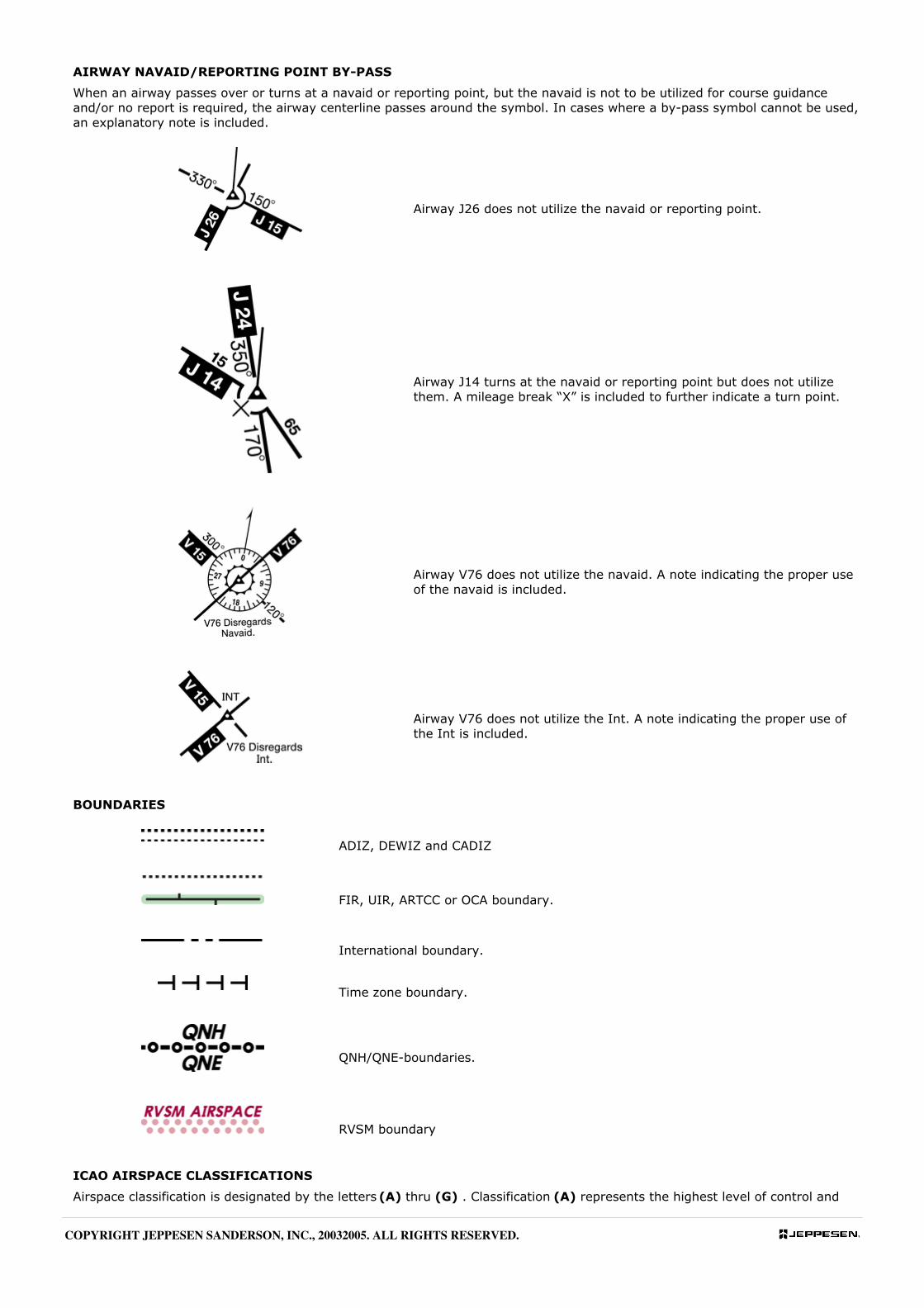
AIRWAY NAVAID/REPORTING POINT BY-PASS
When an airway passes over or turns at a navaid or reporting point, but the navaid is not to be utilized for course guidance
and/or no report is required, the airway centerline passes around the symbol. In cases where a by-pass symbol cannot be used,
an explanatory note is included.
Airway J26 does not utilize the navaid or reporting point.
Airway J14 turns at the navaid or reporting point but does not utilize
them. A mileage break “X” is included to further indicate a turn point.
Airway V76 does not utilize the navaid. A note indicating the proper use
of the navaid is included.
Airway V76 does not utilize the Int. A note indicating the proper use of
the Int is included.
BOUNDARIES
ADIZ, DEWIZ and CADIZ
FIR, UIR, ARTCC or OCA boundary.
International boundary.
Time zone boundary.
QNH/QNE-boundaries.
RVSM boundary
ICAO AIRSPACE CLASSIFICATIONS
Airspace classification is designated by the letters (A) thru (G) . Classification (A) represents the highest level of control and
COPYRIGHT JEPPESEN SANDERSON, INC., 20032005. ALL RIGHTS RESERVED.
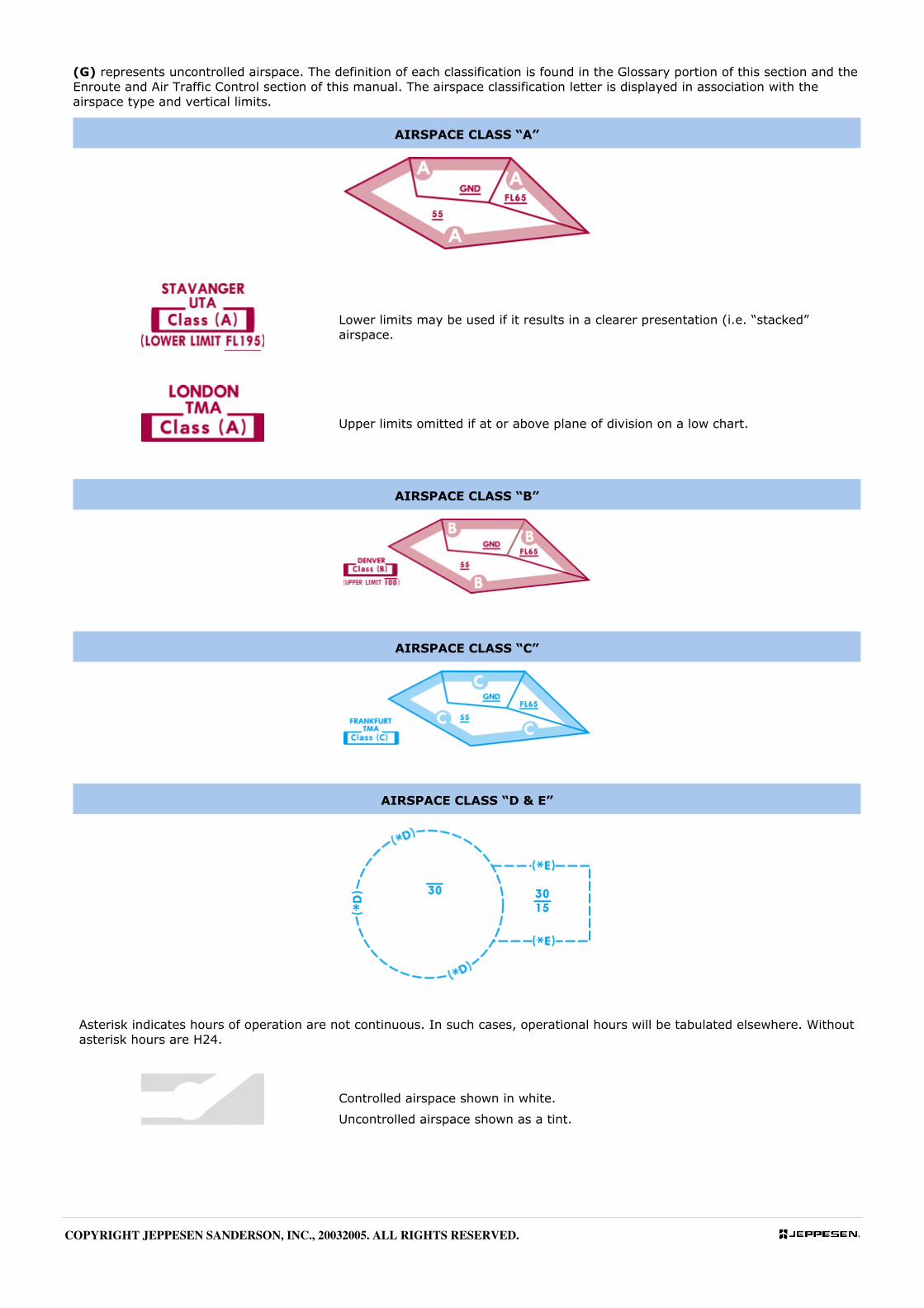
(G) represents uncontrolled airspace. The definition of each classification is found in the Glossary portion of this section and the
Enroute and Air Traffic Control section of this manual. The airspace classification letter is displayed in association with the
airspace type and vertical limits.
AIRSPACE CLASS “A”
Lower limits may be used if it results in a clearer presentation (i.e. “stacked”
airspace.
Upper limits omitted if at or above plane of division on a low chart.
AIRSPACE CLASS “B”
AIRSPACE CLASS “C”
AIRSPACE CLASS “D & E”
Asterisk indicates hours of operation are not continuous. In such cases, operational hours will be tabulated elsewhere. Without
asterisk hours are H24.
Controlled airspace shown in white.
Uncontrolled airspace shown as a tint.
COPYRIGHT JEPPESEN SANDERSON, INC., 20032005. ALL RIGHTS RESERVED.
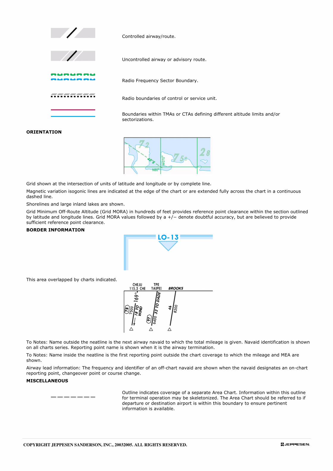
Controlled airway/route.
Uncontrolled airway or advisory route.
Radio Frequency Sector Boundary.
Radio boundaries of control or service unit.
Boundaries within TMAs or CTAs defining different altitude limits and/or
sectorizations.
ORIENTATION
Grid shown at the intersection of units of latitude and longitude or by complete line.
Magnetic variation isogonic lines are indicated at the edge of the chart or are extended fully across the chart in a continuous
dashed line.
Shorelines and large inland lakes are shown.
Grid Minimum Off-Route Altitude (Grid MORA) in hundreds of feet provides reference point clearance within the section outlined
by latitude and longitude lines. Grid MORA values followed by a +/− denote doubtful accuracy, but are believed to provide
sufficient reference point clearance.
BORDER INFORMATION
This area overlapped by charts indicated.
To Notes: Name outside the neatline is the next airway navaid to which the total mileage is given. Navaid identification is shown
on all charts series. Reporting point name is shown when it is the airway termination.
To Notes: Name inside the neatline is the first reporting point outside the chart coverage to which the mileage and MEA are
shown.
Airway lead information: The frequency and identifier of an off-chart navaid are shown when the navaid designates an on-chart
reporting point, changeover point or course change.
MISCELLANEOUS
Outline indicates coverage of a separate Area Chart. Information within this outline
for terminal operation may be skeletonized. The Area Chart should be referred to if
departure or destination airport is within this boundary to ensure pertinent
information is available.
COPYRIGHT JEPPESEN SANDERSON, INC., 20032005. ALL RIGHTS RESERVED.
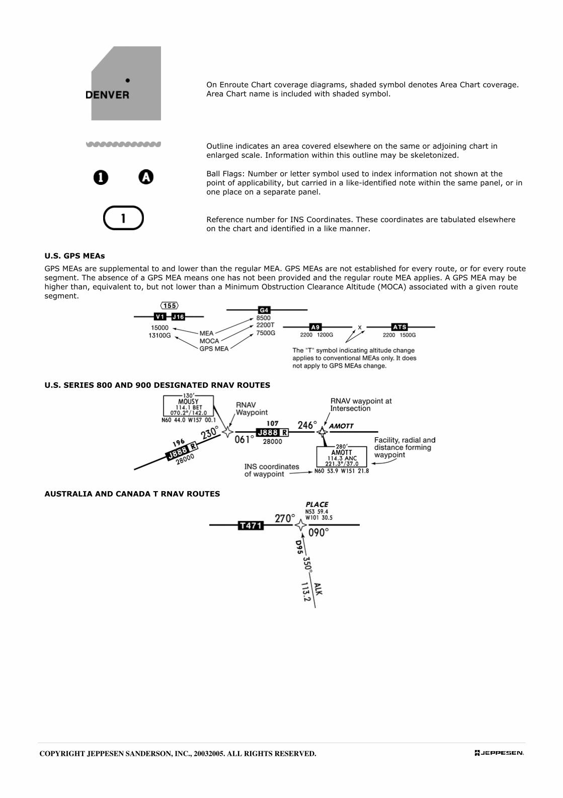
On Enroute Chart coverage diagrams, shaded symbol denotes Area Chart coverage.
Area Chart name is included with shaded symbol.
Outline indicates an area covered elsewhere on the same or adjoining chart in
enlarged scale. Information within this outline may be skeletonized.
Ball Flags: Number or letter symbol used to index information not shown at the
point of applicability, but carried in a like-identified note within the same panel, or in
one place on a separate panel.
Reference number for INS Coordinates. These coordinates are tabulated elsewhere
on the chart and identified in a like manner.
U.S. GPS MEAs
GPS MEAs are supplemental to and lower than the regular MEA. GPS MEAs are not established for every route, or for every route
segment. The absence of a GPS MEA means one has not been provided and the regular route MEA applies. A GPS MEA may be
higher than, equivalent to, but not lower than a Minimum Obstruction Clearance Altitude (MOCA) associated with a given route
segment.
U.S. SERIES 800 AND 900 DESIGNATED RNAV ROUTES
AUSTRALIA AND CANADA T RNAV ROUTES
COPYRIGHT JEPPESEN SANDERSON, INC., 20032005. ALL RIGHTS RESERVED.
COPYRIGHT JEPPESEN SANDERSON, INC., 20032005. ALL RIGHTS RESERVED.

COPYRIGHT JEPPESEN SANDERSON, INC., 20032005. ALL RIGHTS RESERVED.


