
Contractor Construction Staking - KDOT: Home · 2.0 Contractor Construction Staking 2.1 General...
13
Kansas Department of Transportation Bridge Construction Manual Version 5/13 KDOT Bridge Section 2.0 - Contractor Construction Staking - i Contractor Construction Staking Table of Contents 2.0 Contractor Construction Staking .......................................................................................... 1 2.1 General Items, Equipment & Methods ................................................................................. 1 2.2 Surveying and Staking Critical Bridge Elements ................................................................ 2 List of Figures Figure 2.2.1 Culvert Staking ........................................................................................................... 3 Figure 2.2.2 Multi-Cell Culvert Staking .........................................................................................4 Figure 2.2.3 Bridge Staking ............................................................................................................. 5 Figure 2.2.4: Table 802-1a of KDOT Specifications ...................................................................... 7 Appendix Appendix A ..................................................................................................................................... 1 Appendix B: Glossary ..................................................................................................................... 1
Transcript of Contractor Construction Staking - KDOT: Home · 2.0 Contractor Construction Staking 2.1 General...
Kansas Department of Transportation Bridge Construction Manual
Contractor Construction Staking
Table of Contents2.0 Contractor Construction Staking ..........................................................................................12.1 General Items, Equipment & Methods .................................................................................12.2 Surveying and Staking Critical Bridge Elements ................................................................ 2
List of FiguresFigure 2.2.1 Culvert Staking ...........................................................................................................3Figure 2.2.2 Multi-Cell Culvert Staking .........................................................................................4Figure 2.2.3 Bridge Staking.............................................................................................................5Figure 2.2.4: Table 802-1a of KDOT Specifications ......................................................................7
AppendixAppendix A .....................................................................................................................................1Appendix B: Glossary .....................................................................................................................1
Version 5/13 KDOT Bridge Section 2.0 - Contractor Construction Staking - i
Kansas Department of Transportation Bridge Construction Manual
Disclaimer: This website and documents are provided for use by persons outside of the Kansas Department of Transportation as
information only. The Kansas Department of Transportation, the State of Kansas, nor its officers or employees, by making this
website and documents available for use by persons outside of KDOT, does not undertake any duties or responsibilities of any such
person or entity who chooses to use this website and documents. This website and documents should not be substituted for the
exercise of a person�s own professional judgment nor the determination by contractors of the appropriate manner and method of
construction on projects under their control. It is the user�s obligation to make sure that he/she uses the appropriate practices. Any
person using this website and documents agrees that KDOT will not be liable for any commercial loss; inconvenience; loss of use,
time, data, goodwill, revenues, profits, or savings; or any other special, incidental, indirect, or consequential damages in any way
related to or arising from use of this website and documents.
.
Version 5/13 KDOT Bridge Section 2.0 - Contractor Construction Staking - ii
Kansas Department of Transportation Bridge Construction Manual
2.0 Contractor Construction Staking
2.1 General Items, Equipment & MethodsThe goal of construction staking is to produce a structure that is located both vertically and hori-zontally as directed on the plans when completed. Construction staking is conducted throughout construction at the stages and locations defined in the Specifications. Other surveys that are not required by the specifications may be needed. A standard of care that includes people trained in surveying techniques is required. Work is to be performed under the supervision of a licensed sur-veyor at a minimum. Errors in alignment and height have occurred previously when these steps were not performed. In some cases they resulted in a substantial loss of time and money.
The contractor is responsible for surveying and construction staking of structures. Staking by the contractor generally is performed by either employees on staff or hired consultants. The construc-tion staking by either of whom must be at a minimum overseen by a licensed surveyor. Even though the construction staking is performed by non-KDOT personnel, at a minimum it is impor-tant and beneficial for construction inspectors to possess a working knowledge of surveying tech-niques .This working knowledge enables the inspector to spot and address questionable practices and busts in a survey. If questions or concerns arise upon inspection of the survey notes consult with the district surveyor. The district surveyor is a good source of information and can offer guidance when the inspector lacks knowledge or experience in construction staking.
An important and often overlooked way of stopping these errors is to include a minimum of two temporary benchmarks in all level loops when establishing the elevation of critical bridge ele-ments. Two temporary benchmarks in a level loop is intended to make sure the accuracy of tem-porary benchmarks is maintained. When crossing a stream, place enough temporary benchmarks on both sides of the stream so that level loops still include a minimum of two temporary bench-marks. The inclusion of two benchmarks in a level loop is considered good technique and practice among reputable surveyors and KDOT surveying management. The practice of balancing shots should also be implemented when running level loops. The reason for balancing shots is to negate equipment and environmental errors that would not be addressed otherwise.
The stakes, disks, spikes and any other item used to mark and establish a point of interest or benchmark during the construction process will follow the guidelines found in the Standard Spec-ifications Sections 102 & 802 and the Special Provisions associated with these sections. Disk(s) and brass placards should be placed according to plan sheets.
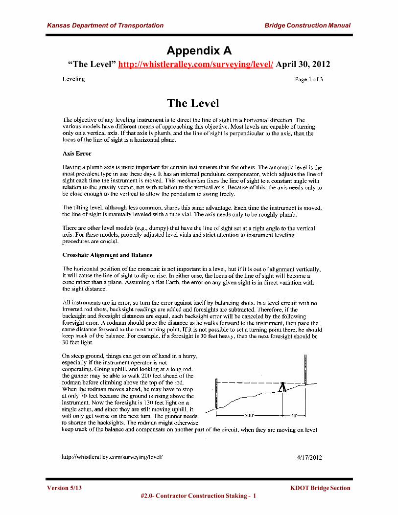
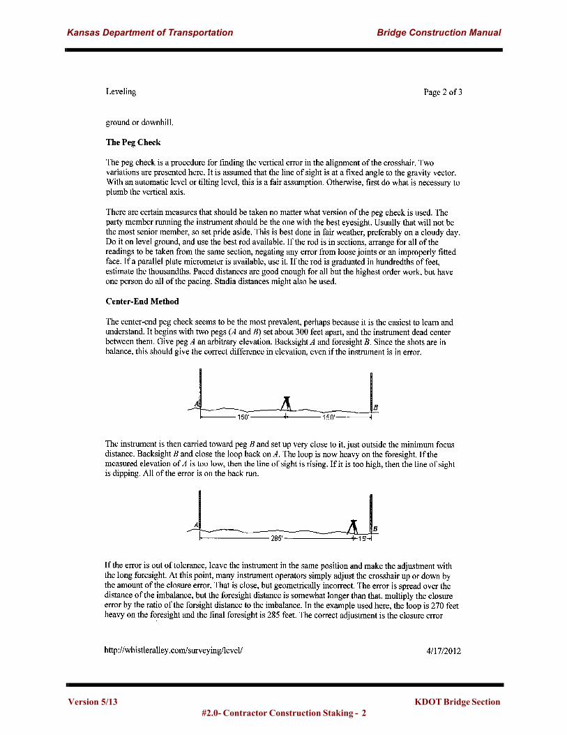
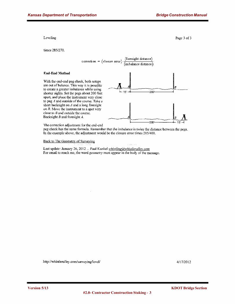
GPS systems and total stations that meet tolerance can be used for horizontal layout and staking of critical bridge members. The checking and setting of elevations for critical bridge members shall be done with an auto-level. All GPS, total stations, and levels should be routinely cleaned and calibrated by a reputable equipment dealer or qualified repair personnel. It is advisable that KDOT personnel be familiar with the process of pegging the level. The familiarity with this pro-cess is intended to help maintain the precision of a KDOT level so it is not compromised. The methodology of pegging the level is located in Appendix A of this chapter. The precision of the level is crucial when KDOT personnel are performing elevation checks during construction. If chains or steel tapes are being used for construction staking they should be pulled consistantly to
Version 5/13 KDOT Bridge Section 2.0 - Contractor Construction Staking - 1
Kansas Department of Transportation Bridge Construction Manual
the correct tension during each measurement. The amount of correction due to ambient air tem-perature should be noted in the surveyor’s notes during the time the measurements were taken.
Establishing temporary benchmarks is necessary for achieving the desired elevation on critical bridge elements. The following steps will increase the chances for producing reliable temporary benchmarks.
• The new temporary benchmark should be located in an area that will not hinder or impede the construction process(es) of the contractor.
• The benchmark should be clearly marked with highly visible flagging and staking to indicate its importance and that it should not be disturbed.
• The new temporary benchmark shall be established such that it resists vertical displacements. a). Set temporary benchmarks in power poles, the trunk of large healthy trees, and on per-manent structures with stable foundations that are sufficiently deep enough to resist heave are preferred. b). Consider and address frost heave on larger projects that will take more than one con-struction season to complete. Place rods that are at least 6 inches longer than the depth required to penetrate past the frost zone. Place benchmarks on large foundations or objects that extend well below the frost zone. c). Do not place a temporary benchmark on a recently placed fill as settlement will occur causing an inaccurate benchmark elevation.d). Confirm that the temporary benchmarks are robust enough to resist accidental strikes by construction personnel. For example, inadvertently being stepped on, tools being set on, or light loads of material being placed on.
• Establish enough benchmarks that multiple benchmarks are still intact and can be used in the case one or more benchmarks are destroyed during construction.
2.2 Surveying and Staking Critical Bridge ElementsArrange to meet with the contractor and/or foreman prior to beginning the staking process to thor-oughly explain the importance of staking the abutments and piers for bridges. The explanation of the “double-check” survey of critical bridge elements prior to starting construction of critical bridge elements as defined by KDOT. Critical bridge elements are defined by KDOT Standard Specifications.
Set all stakes and benchmarks for structures with an offset distance and placement in a manner that attempts to stop their destruction during construction. Consulting the contractor or their staff can aid in the best placement of the structure stakes to provide longevity of stakes for the duration of construction. It is advisable to stake the structure in its entirety prior to beginning construction. It is good practice to set sufficient points so that in the case some points are disturbed a minimum of three valid points are still visible from all setup spots. This becomes important in the reestab-lishment of a line which should always include a minimum of three points of reference. Establish enough points on both sides of a stream crossing that the reestablishment of a line from a mini-mum of three valid points is achievable.
Version 5/13 KDOT Bridge Section #2.0- Contractor Construction Staking - 2
Kansas Department of Transportation Bridge Construction Manual
Mark construction stakes to denote if they are located on center line of the structural element or center line of traffic. To advoid confusion at a lator time, when setting an offset stake reference center line of either the structural element or traffic. Note that the center line of a structure is not always the center line of traffic. This is due to different shoulder widths, sidewalks, or turning lanes on a bridge for example.
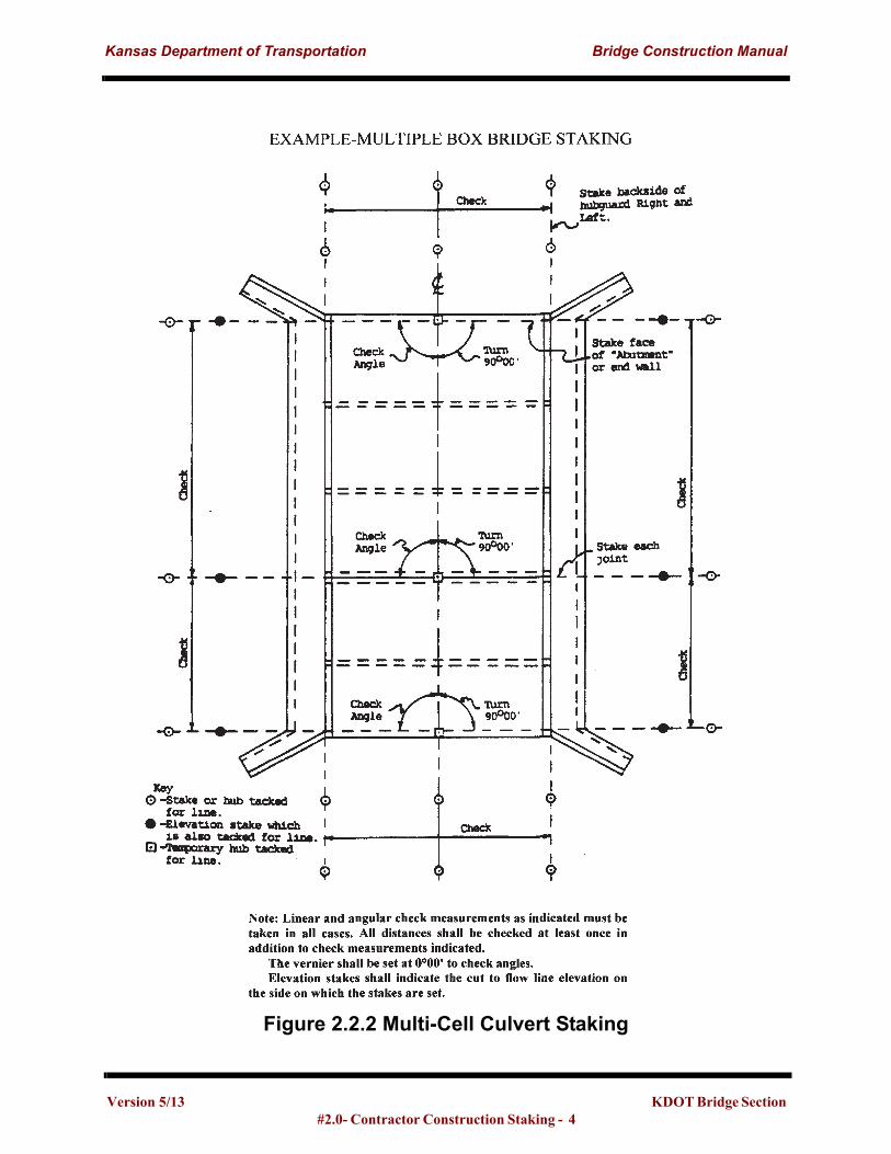
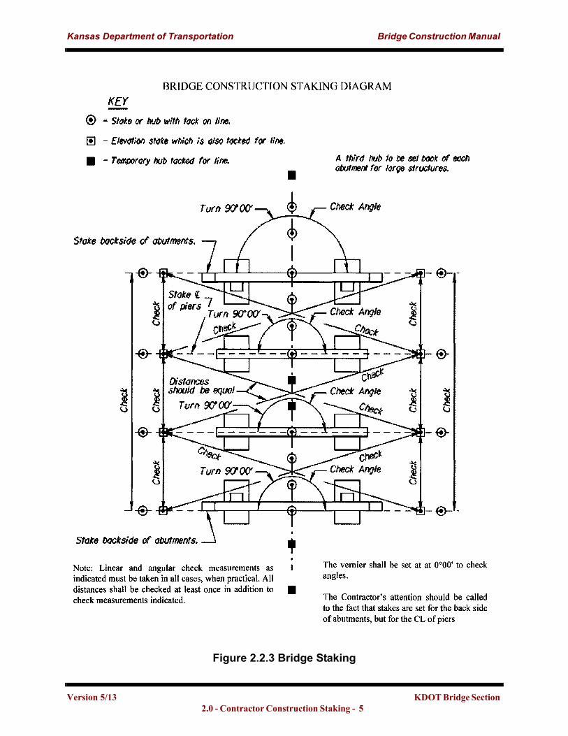
The following common practices and a typical bridge layout(s) are taken from Section 3.23.02 of the “1999 Kansas Department of Transportation Construction Manual”. Figures 2.2.1, 2.2.2, and 2.2.3 describe and illustrate those practices.
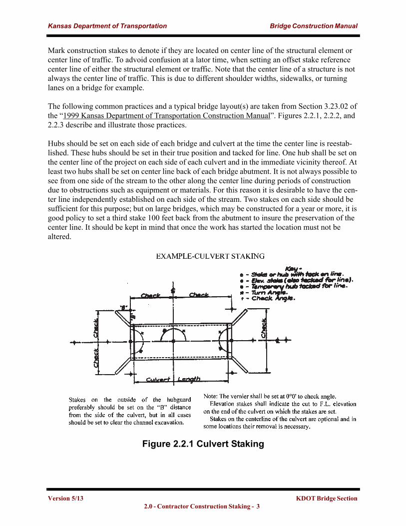
Hubs should be set on each side of each bridge and culvert at the time the center line is reestab-lished. These hubs should be set in their true position and tacked for line. One hub shall be set on the center line of the project on each side of each culvert and in the immediate vicinity thereof. At least two hubs shall be set on center line back of each bridge abutment. It is not always possible to see from one side of the stream to the other along the center line during periods of construction due to obstructions such as equipment or materials. For this reason it is desirable to have the cen-ter line independently established on each side of the stream. Two stakes on each side should be sufficient for this purpose; but on large bridges, which may be constructed for a year or more, it is good policy to set a third stake 100 feet back from the abutment to insure the preservation of the center line. It should be kept in mind that once the work has started the location must not be altered.
Figure 2.2.1 Culvert Staking
Version 5/13 KDOT Bridge Section 2.0 - Contractor Construction Staking - 3
Kansas Department of Transportation Bridge Construction Manual
Figure 2.2.2 Multi-Cell Culvert Staking
Version 5/13 KDOT Bridge Section #2.0- Contractor Construction Staking - 4
Kansas Department of Transportation Bridge Construction Manual
Figure 2.2.3 Bridge Staking
Version 5/13 KDOT Bridge Section 2.0 - Contractor Construction Staking - 5
Kansas Department of Transportation Bridge Construction Manual
“Prior to construction, provide an independent survey performed under the supervision of a differ-ent Licensed Professional Land Surveyor to check the accuracy of the original survey of project control points and locations of the Critical Bridge Elements features”. The intent of this phrase is to result in a “double-check” scenario where a second independent and distinct survey is per-formed. The two independent surveys resulting in physically separate and unique field notes that use seperate points in the survey. If the second survey does not accomplish these tasks then the accuracy of the first survey has not been verified. The two surveys required by specifications are both to be performed at a minimum under the supervision of a licensed surveyor. Refer to Kansas Standard Specifications.
The tolerance for staking critical bridge members is feet in the horizontal direction and
feet in the vertical direction. It is necessary to track and record atmospheric changes peri-odically while collecting measurements. Recording of atmospheric changes is also required when changes become noticeable to the operator’s senses. This will allow the operator to enter the cor-rect atmospheric pressure and temperature when using an electronic measuring device or a total station while performing measurements to obtain the correct measurements. The use of a chain or steel tape also needs to be corrected for temperature when making measurements to set points and stakes for construction. Measure each individual angle a minimum of 2 times with the instrument in the direct position and an equal number of times with the instrument in the reverse position when performing triangulation work. Average the results of the measured values for an angle that was measured. No single measurement in the averaged set can differ more than 30 seconds from the average value. The reason for taking and recording diagonal measurements in field is to con-firm that the structure or the layout of the structure is squared up.
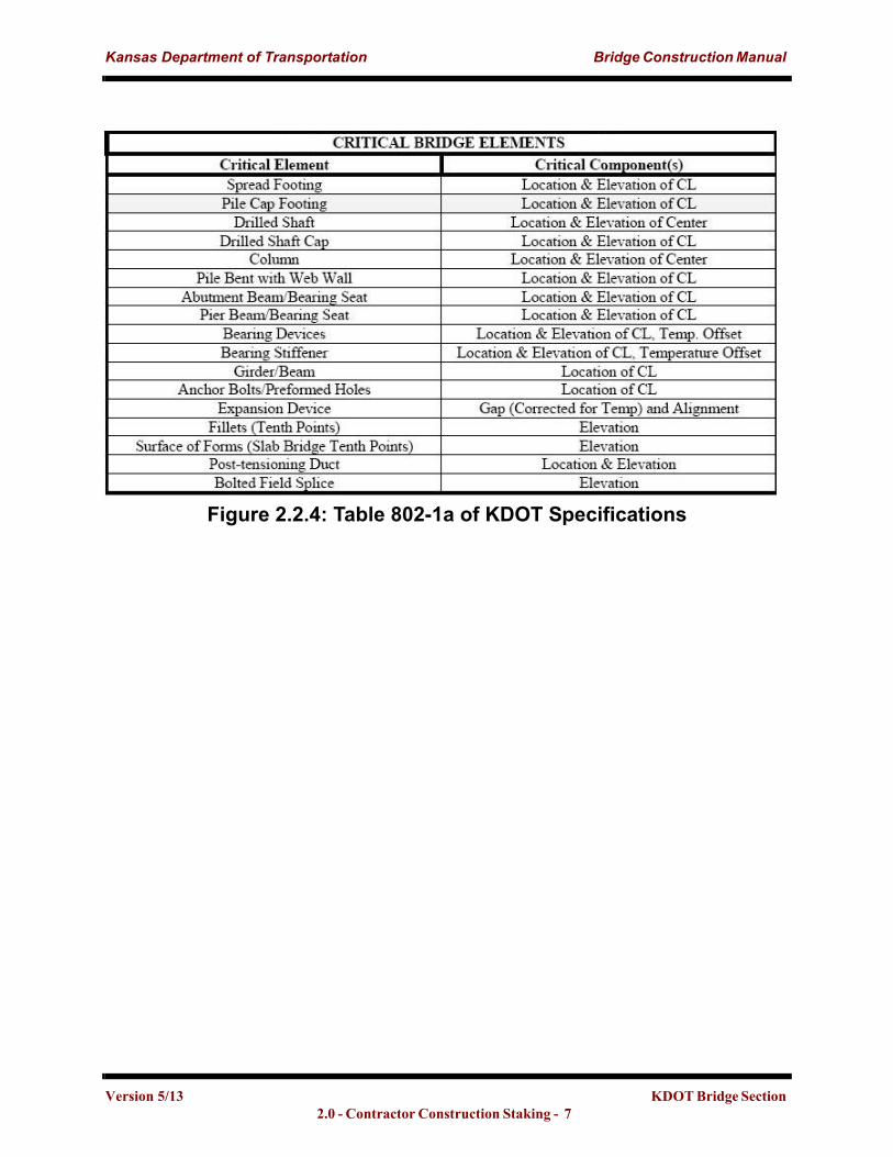
The critical bridge elements found in the standard specifications that require a dual survey prior to building and once upon completion of construction are in the table below in Figure 2.2.4: Table 802-1a of KDOT Specifications. In addition to the structural elements in Figure 2.2.4: Table 802-1a of KDOT Specifications all handrail posts including forms for cast-in-place post shall be aligned and elevations set by using the proper surveying equipment prior to placing concrete. Special attention should be given to the alignment and spacing of piers and abutments as these elements are fundamental elements and are the corner stones of construction essential in achiev-ing the proper location, elevations, and physical aspects of the bridge. If the piers or abutments are misaligned, prefabricated beams delivered to the project site will not fit. The solution to the mis-fitting beam issue is foundations will have to be modified if deemed safe and appropriate by bridge design or the foundations may require a complete replacement. The cost associated with having to execute either of these options are at the contractor’s expense.
0.± 02
0.01±
Version 5/13 KDOT Bridge Section #2.0- Contractor Construction Staking - 6
Kansas Department of Transportation Bridge Construction Manual
Figure 2.2.4: Table 802-1a of KDOT Specifications�
Version 5/13 KDOT Bridge Section 2.0 - Contractor Construction Staking - 7
Kansas Department of Transportation Bridge Construction Manual
Appendix A“The Level” http://whistleralley.com/surveying/level/ April 30, 2012
Version 5/13 KDOT Bridge Section #2.0- Contractor Construction Staking - 1
Kansas Department of Transportation Bridge Construction Manual
Version 5/13 KDOT Bridge Section #2.0- Contractor Construction Staking - 2
Kansas Department of Transportation Bridge Construction Manual
Version 5/13 KDOT Bridge Section #2.0- Contractor Construction Staking - 3
Kansas Department of Transportation Bridge Construction Manual
Appendix B: Glossary
BenchMark: a point of known elevation from which other point(s) elevation may be determined.
Bust: term used to denote that measurements taken disagree on the location or elevation of a point of interest.
Critical Bridge Elements: components of the bridge that must be located correctly during con-struction in order to achieve proper alignment and elevations of the bridge upon completion.
GPS: acronym for Global Positioning System. System which uses electronic measuring devices which send and receive signals to orbiting satellites in order to triangulate the devices position and make measurements.
Hub: typically a wooden two inch by two inch pointed stake that is driven into the ground and used as a reference point in a survey. Can have a nail driven into the top of it to provide a precise point for future reference.
Level Loop: a series of measurements where backsights and foresights are taken between turn points. The turn points should include at least 2 benchmarks in order to establish the elevation of an unknown point.
Pegging the Level: method to find, determine, and correct the amount of error in the inclination of the reticle in the optics of an auto-level.
Stake: a long slender usually wooden element driven into the ground to produce a reference point which may have offset, centerline station, elevation, and cut or fill depth written on it.
Tacked for line: to drive a tack (nail) into a point on the hubs which creates a perfect line when the tacks are aligned.
Total Station: an electronic/optical instrument which measures angles in both the horizontal and vertical axes and is capable of measuring distances by use of an electronic distance meter.
Balancing Shots: attempting to keep the length of foreshots (FS) and backshots (BS) equivalent at each equipment setup in order to cancel out any equipment and atmospheric errors caused by unequal length of shots.
Heavy: longer shot taken in either the FS or BS when compared to the counter shot
Light: shorter shot taken in either the FS or BS when compared to the counter shot
Gunner: person operating the equipment that takes the desired measurements
Squared up: angles on the corners of the bridge are identical.
Version 5/13 KDOT Bridge Section 2.0- Contractor Construction Staking - 1