Contents Staf - eletri.com.br · Contents Staf Page Technical ... Hoods/Housings sealing NBR...
12
09 . 01 Staf Contents Staf Page Technical characteristics Staf . . . . . . . . . . . . . . . . . . . . . . . . . . . . . . . . . . . . 09.10 Staf 6 . . . . . . . . . . . . . . . . . . . . . . . . . . . . . . . . . . . . . . . . . . . . . . . . . . . . . 09.11 Staf 14 . . . . . . . . . . . . . . . . . . . . . . . . . . . . . . . . . . . . . . . . . . . . . . . . . . . . . 09.14 Staf 20 . . . . . . . . . . . . . . . . . . . . . . . . . . . . . . . . . . . . . . . . . . . . . . . . . . . . . 09.16 Staf 40 . . . . . . . . . . . . . . . . . . . . . . . . . . . . . . . . . . . . . . . . . . . . . . . . . . . . . 09.18
Transcript of Contents Staf - eletri.com.br · Contents Staf Page Technical ... Hoods/Housings sealing NBR...

09.01
Staf
Contents
Staf Page
Technical characteristics Staf . . . . . . . . . . . . . . . . . . . . . . . . . . . . . . . . . . . . 09.10
Staf 6 . . . . . . . . . . . . . . . . . . . . . . . . . . . . . . . . . . . . . . . . . . . . . . . . . . . . . 09.11
Staf 14 . . . . . . . . . . . . . . . . . . . . . . . . . . . . . . . . . . . . . . . . . . . . . . . . . . . . . 09.14
Staf 20 . . . . . . . . . . . . . . . . . . . . . . . . . . . . . . . . . . . . . . . . . . . . . . . . . . . . . 09.16
Staf 40 . . . . . . . . . . . . . . . . . . . . . . . . . . . . . . . . . . . . . . . . . . . . . . . . . . . . . 09.18

09.10
Staf Technical characteristics
Current carrying capacityThe current carrying capacity is limited by maximum temperatureof materials for inserts and contacts including terminals. Thecurrent capacity-curve is valid for continuous, not interruptedcurrent-loaded contacts of connectors when simultaneous poweron all contacts is given, without exceeding the maximum tempe-rature.
Control and test procedures according to DIN IEC 60 512-3.
Wor
king
cur
rent
Ambient temperature
Wire gauge: 1 mm2
Staf 6 Staf 14 Staf 20
Specifications DIN VDE 0627DIN VDE 0110
Approvals , , SEV, BVS,CERCHAR, SABS
InsertsNumber of contacts 6, 14, 20, 40 (2 x 20)Working current 10 A max.
(see current carrying capacity)Working voltage 25 V ~ / 60 V –Test voltage Urms 1.5 kVPollution degree 3 (C)Insulation resistance ≥ 1010 ΩMaterial PolyamideTemperature range - 40 OC … +100 OCFlammability acc. to UL 94 HBMechanical working life
- Mating cycles ≥ 500Working voltageacc. to UL/CSA 50 V
ContactsMaterial copper alloySurface
- hard-silver plated 3 µm AgContact resistance ≤ 2 mΩScrew terminal
- mm2 1.5 mm²- AWG 16- Tightening/test torque 0.5 Nm
Solder terminal- mm2 2.5 mm²- AWG 14
Hoods/HousingsMaterial die cast aluminium alloy
Staf 6 additional thermoplastic resinFlammability acc. to UL 94 V 0
Surface powder-coated RAL 7037Locking element Steel, zinc platedHoods/Housings sealing NBRTemperature range - 40 OC … +125 OCDegree of protection acc. to DIN40 050 for coupled connector IP 65 in plastic housings
Staf 6 IP 44 in metal housings
Further selectionof hoods/housings chapter 30
AccessoriesCable clamps chapter 40Coding of hoods/housings chapter 40Label acc. to CSA-approval chapter 40Test connectors chapter 20
Staf

09.11
Number of contacts
6
Staf
Screw terminal Staf
09 70 006 2813 09 70 006 2616
Solder terminal Staf
09 70 006 2812 09 70 006 2615
Staf 6
Part No.
Identification Series Female insert (M) Male insert (F) Drawing Dimensions in mm
Inserts
Contact arrangementView from termination side
Contact arrangementView from termination side
Mounting example
25 V ~ 10 A60 V –
Stock items in bold type
09.12
Staf
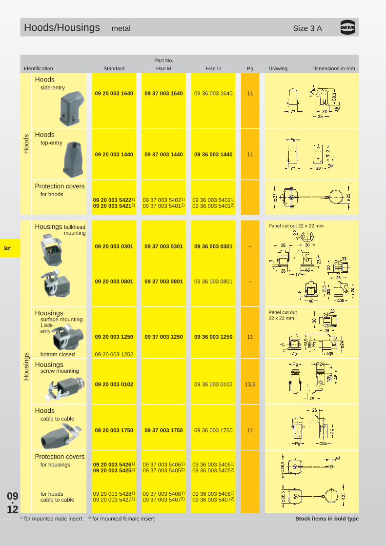
Hoods/Housings metal Size 3 A
Part No.
Identification Standard Han M Han U Pg Drawing Dimensions in mm
Hoo
dsH
ousi
ngs
1) for mounted male insert 2) for mounted female insert
Housings bulkheadmounting
09 20 003 0301 09 37 003 0301 09 36 003 0301 –
09 20 003 0801 09 37 003 0801 09 36 003 0801 –
Housingssurface mounting1 side-entry
09 20 003 1250 09 37 003 1250 09 36 003 1250 11
bottom closed 09 20 003 1252
Hoodscable to cable
09 20 003 1750 09 37 003 1750 09 36 003 1750 11
Protection coversfor hoods
09 20 003 54221) 09 37 003 54021) 09 36 003 54021)
09 20 003 54212) 09 37 003 54012) 09 36 003 54012)
Protection coversfor housings 09 20 003 54261) 09 37 003 54061) 09 36 003 54061)
09 20 003 54252) 09 37 003 54052) 09 36 003 54052)
for hoods 09 20 003 54281) 09 37 003 54081) 09 36 003 54081)
cable to cable 09 20 003 54272) 09 37 003 54072) 09 36 003 54072)
Panel cut out 22 x 22 mm
Panel cut out22 x 22 mm
Hoodsside-entry
09 20 003 1640 09 37 003 1640 09 36 003 1640 11
Hoodstop-entry
09 20 003 1440 09 37 003 1440 09 36 003 1440 11
Housingsscrew mounting
09 20 003 0102 09 36 003 0102 13,5
Stock items in bold type

09.13
A B
C
Staf
Stock items in bold type
Hoods/Housings thermoplastic Size 3 A
Identification Part No. Pg Drawing Dimensions in mm
Hoo
ds
Hoodsside-entry grey
09 20 003 0620 11
black09 20 003 0627 11
Hoodstop-entry grey
09 20 003 0420 11
black09 20 003 0427 11
Protection coversfor hoods
09 20 003 54421)
09 20 003 54412)
Hou
sing
s
Housings bulkhead mountinggrey
09 20 003 0320 –
black09 20 003 0327 –
grey09 20 003 0820 –
black09 20 003 0827 –
Housingssurface mounting 1 side-entry grey
09 20 003 0220 11
black09 20 003 0227 11
Housings screw mountinggrey
09 20 003 0120 13.5
black09 20 003 0127 13.5
Hoods cable to cablegrey
09 20 003 0720 11
black09 20 003 0727 11
Panel cut out 22 x 22 mm
Panel cut out 22 x 22 mm
Protection coversfor housings A 09 20 003 54071)3)
09 20 003 54082)3)
B 09 20 003 54461)1)
09 20 003 54452)1)
for hoods cable to cable C 09 20 003 54481)1)
1) for mounted male insert2) for mounted female insert3) for metal housings and cable to cable hoods also

09.14
Staf
Screw terminal Staf
09 70 014 2811 09 70 014 2614
Solder terminal Staf
09 70 014 2810 09 70 014 2613
Staf 14
Part No.
Identification Series Female insert (M) Male insert (F) Drawing Dimensions in mm
Inserts
Number of contacts
14
25 V ~ 10 A60 V –
Panel cut out for insertsfor use without hoods/housings
Contact arrangement View from termination side
1) Distance for contact max. 24 mm
Stock items in bold type

09.15
Staf
Hoodsside-entry
09 20 010 1541 16
09 20 010 0540 1609 20 010 0541 21
Hoodstop-entry
09 20 010 1440 13.5
09 20 010 0440 1609 20 010 0441 21
Hoo
ds
Housingsbulkhead mounting
09 20 010 0301 –
with thermo-plastic cover
09 20 010 0321 –
Housingssurface mounting
1 side-entry 09 20 010 0251 1609 20 010 0252 21
with thermo-plastic cover
09 20 010 0221 1609 20 010 0222 21
2 side-entries 09 20 010 0291 16
with thermo-plastic cover
09 20 010 0296 16
Hou
sing
sStandard Hoods/Housings with 1 lever on the housing Size 10 A
Part No.
Identification Low construction High construction Pg Drawing Dimensions in mm
Stock items in bold type

09.16
Staf
Screw terminal Staf
09 70 020 2817 09 70 020 2622
Solder terminal Staf
09 70 020 2816 09 70 020 2621
Staf 20
Part No.
Identification Series Female insert (M) Male insert (F) Drawing Dimensions in mm
Inserts
Number of contacts
20
25 V ~ 10 A60 V –
Panel cut out for insertsfor use without hoods/housings
Contact arrangement View from termination side
1) Distance for contact max. 24 mm
Stock items in bold type

09.17
Staf
Hoodsside-entry
09 20 016 1541 16
09 20 016 0540 1609 20 016 0541 21
Hoodstop-entry
09 20 016 1441 16
09 20 016 0440 1609 20 016 0441 21
Hoo
ds
Housingsbulkhead mounting
09 20 016 0301 –
with thermo-plastic cover
09 20 016 0321 –
Housingssurface mounting
1 side-entry 09 20 016 0251 1609 20 016 0252 21
with thermo-plastic cover
09 20 016 0221 1609 20 016 0222 21
2 side-entries 09 20 016 0291 16
with thermo-plastic cover
09 20 016 0296 16
Hou
sing
sStandard Hoods/Housings with 1 lever on the housing Size 16 A
Part No.
Identification Low construction High construction Pg Drawing Dimensions in mm
Stock items in bold type

09.18
Staf
Screw terminal Staf
1–20 09 70 020 2817 09 70 020 26221–20 09 70 020 2817 09 70 020 2622
Solder terminal Staf
1–20 09 70 020 2816 09 70 020 26211–20 09 70 020 2816 09 70 020 2621
Staf 40
Part No.
Identification Series Female insert (M) Male insert (F) Drawing Dimensions in mm
Inserts
Number of contacts
40
25 V ~ 10 A60 V –
Panel cut out for insertsfor use without hoods/housings
Dimensions for inserts see page 09.16
Contact arrangement View from termination side
Stock items in bold type

09.19
Staf
Hoodsside-entry
09 20 032 1520 21
09 20 032 0520 2109 20 032 0521 29
Hoodstop-entry
09 20 032 0420 2109 20 032 0421 29
Hoo
ds
Housingbulkhead mounting
09 20 032 0301 –
Housingssurface mounting
1 side-entry 09 20 032 0230 2109 20 032 0231 29
2 side- 09 20 032 0270 21entries 09 20 032 0271 29
Hou
sing
s
Hood with centrallockinglever
side-entry09 20 032 0581 29
Housing for centrallocking
bulkheadmounting
09 20 032 0381 –
Standard Hoods/Housings with 2 levers on the housing Size 32 A
Part No.
Identification Low construction High construction Pg Drawing Dimensions in mm
Panel cut out
Blind wayfor one cable entry
Stock items in bold type

09.20
Staf
Notes