CONTENT - · PDF fileVAL-01 controller is an innovative microprocessor device, which...
14
-
Upload
truongkhue -
Category
Documents
-
view
219 -
download
1
Transcript of CONTENT - · PDF fileVAL-01 controller is an innovative microprocessor device, which...


CONTENT
SAFETY OF USE........................................................................................................................3
INSTALLATION RECOMMENDATIONS.............................................................................................................3
TECHNICAL DATA...................................................................................................................4
PURPOSE....................................................................................................................................5
OPERATING PRINCIPLE.................................................................................................................................5
CONNECTION SCHEME..........................................................................................................6
CONSTRUCTION OF ELECTRONIC CONTROLLER...........................................................................................................................7
CONTROL PANEL.....................................................................................................................8
INSTALLATION.........................................................................................................................9
USE OF CONTROL DEVICE...................................................................................................13
PACKAGE CONTENT..................................................................................................................................13
WARRANTY CERTIFICATE...................................................................................................14

SAFETY OF USE
• Before you start using the device, please carefully read this instruction.
• This control device must be installed and connected by corresponding qualified person, who is familiar with the
legislation governing safe use of electrical tools: General rules of the installation of electrical devices (Ţin., 2012,
Nr. 18-816); Safety rules of the operation of electrical equipment (Ţin., 2010, Nr.39-1878); General Regulations of
work equipment usage (Ţin., 2000, Nr. 3-88); Technical Regulation "Safety of Machinery" (Ţin., 2007, Nr.129-
5249) and other legislations, governing this activity. It is necessary to comply with all safety requirements.
• Before connecting the device, check all the connections in order to prevent accidental touch to the electric current;
• Check that wires or cable insulation has no obvious damages, cracks and etc. It is forbidden to use the device if
wires, cables of the device are damaged, as well as other parts of the device;
• If you notice strong overheating of parts and wires, sparking in wires and connectors, or other failures, as well as
feel the smell of burning wires or in case of a power failure, it is NECESSARY to turn off the device from the
power source.
• Before connecting the device to the electricity network, all the connection works of this device must be completed.
• It is necessary to ensure appropriate working conditions, corresponding to the device specifications.
INSTALLATION RECOMMENDATIONS
• It is prohibited to connect this device to the same electrical cables without appropriate network filters, to which
other high-power devices are connected.
• Do not route signal cables near or with energy and power cables.
• Keep a distance of remotely operated devices, avoid high-power overload, avoid device contact with group or phase
control devices, as well as other devices, which may interfere the operation of boiler’s regulator.
• When connecting the device, remember that the building system must be equipped with the connector and automatic
connector. This element has to be close to the controller, easily accessible by the user and marked in a way it would
be clear that it is for the switching off the device.
• The manufacturer is not responsible for damages caused by failure to comply with these instructions.

TECHNICAL DATA
Sensor: LM35
Measurement volume: -55 - +150 °C
Measurement specification: 0,5 °C
Measurement time: 1 s
Control outputs:
• Central heating pump ̴230V 2A (0,8 A)
• Ventilator ̴230V 2A (0,8 A)
• Electric gear 24V 0,1 A
Control inputs:
• Temperature sensor LM35
• Room thermostat closed contact
Marking:
• RGB diode marking of the working condition
Power input: ̴230V 50Hz 2A (0,8 A)
Power output: 15V 0,5A
Operating temperature: 5 °C - 50 °C
Degree of hull protection: IP20
PURPOSE VAL-01 controller is an innovative microprocessor device, which regulates the work of solid fuel boiler Stropuva. The
application of the control device and complex algorithms ensures easy use and automation of the combustion process. This
control device is adapted for work with the central heating pump. This controller also has a possibility to connect with the
room thermostat (not included in the kit), with the help of which you can change the operating parameters of the boiler,
when the temperature of the premises reaches a certain temperature. Depending on the purchased room thermostat, you can
program hourly, daily, weekly, etc. modes.
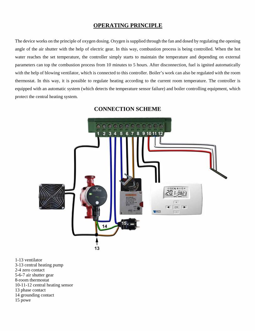
OPERATING PRINCIPLE
The device works on the principle of oxygen dosing. Oxygen is supplied through the fan and dosed by regulating the opening
angle of the air shutter with the help of electric gear. In this way, combustion process is being controlled. When the hot
water reaches the set temperature, the controller simply starts to maintain the temperature and depending on external
parameters can top the combustion process from 10 minutes to 5 hours. After disconnection, fuel is ignited automatically
with the help of blowing ventilator, which is connected to this controller. Boiler’s work can also be regulated with the room
thermostat. In this way, it is possible to regulate heating according to the current room temperature. The controller is
equipped with an automatic system (which detects the temperature sensor failure) and boiler controlling equipment, which
protect the central heating system.
CONNECTION SCHEME
1-13 ventilator 3-13 central heating pump 2-4 zero contact 5-6-7 air shutter gear 8-room thermostat 10-11-12 central heating sensor 13 phase contact 14 grounding contact 15 powe

CONSTRUCTION OF ELECTRONIC CONTROLLER

CONTROL PANEL
Pause switcher:
0 – 10 min 1 – 30 min 2 – 60 min 3 – 90 min 4 – 120 min 5 – 180 min 6 – 240 min 7 – 300 min
Switcher of fuel types:
0 – wood: 1 – carbon 2 – peat briquettes 3 – wood sawdust briquettes 4 – wood sawdust granules

Operating modes of the indicator: Blue color lights – STOP mode. Air supply shutter is closed; ventilator does not work. In this mode, you can load the boiler with fuel and start it up.
Red color lights – initial control. After starting up the boiler and fuel burning well, you have to unhook the ring of the line (lower air distributor on the fuel), press start/stop button START/STOP, wait 10-15 seconds until air supply shutter opens and close the door. Red indicator will light up – initial control. The initial fuel ignition phase is in this mode.
Red/green/blue color flashes – the main control. This mode will be activated, if boiler’s operating temperature will not reach 70 degrees or due to termination and restoration of power supply to the controller.
Blue/red color flashes – no power. The controller is equipped with a reserve accumulator, so in case of power failure, air supply shutter will close automatically.
Green color lights – conditioning before the pause. The boiler is extinguished gradually by limiting the air supply. This mode will be activated when temperature in the boiler will reach 80 degrees or when premises will be warm enough and room thermostat will be activated.
Red color flashes - pause. This is boiler’s standby mode, during which the air supply to the boiler is completely limited and the circulation pump is turned off. The boiler is extinct for a specified period of time or until room thermostat will give a signal to heat the house and at the end of a specified timeout period. After pause, the initial control mode turns on and the process is repeated.
Red/green flashes – 6 h pause. Fuel clean out turns on at longer than 6 hours pause.
Blue flashes –burning out of coals. When fuel burns out and boiler’s temperature reaches 35 degrees, then coals burning mode turns on, during which air is blown into the boiler to the maximum. After coals burning out the boiler switches to STOP mode.
Blue/green flashes – problem with sensor. It is prohibited to burn the boiler at this mode. You need to check connection contacts of the temperature sensor and to fix the connection or contact the service department.

INSTALLATION
Fig. 1 Unscrew thermal regulator of the boiler “STROPUVA” and remove the air shutter.
Fig. 2 Place the rubber seal on air preheating chamber
Fig. 3 Place the holder inside the boiler
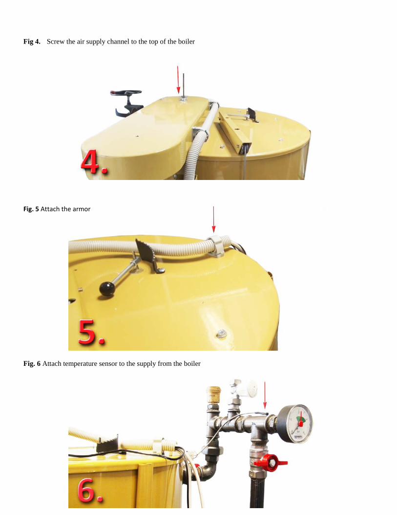
Fig 4. Screw the air supply channel to the top of the boiler
Fig. 5 Attach the armor
Fig. 6 Attach temperature sensor to the supply from the boiler
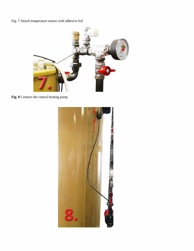
Fig. 7 Attach temperature sensor with adhesive foil
Fig. 8 Connect the central heating pump

Fig. 9 Turn into the grid power Nr. 1 and power Nr. 2. You can use the controller without room thermostat – in such way 8-9 contacts are connected with a connector. If you use the controller with room thermostat – then remove the connector and increase the length of wires up to room thermostat installed in premises.
USE OF CONTROL DEVICE
Make sure that controller is turned on and light diode lights in blue – Stop mode. Before starting up the boiler, set the type of fuel and pause duration. Pause – is time, when the boiler is not burning and is on a standby mode. If you use the controller without room thermostat – we recommend choosing pause duration depending on outside temperature. If it is warm outside – you can choose a longer pause duration, if cold – shorter. Pause duration depends on the heated area and if external thermostat is turned on. If you use it, then the controller automatically selects the length of the pause.
Start burning the top of the fuel load, slightly closing the door leaving a gap of 2-5 cm. When fuel starts burning, remove the ring with the lifting line from the hook and press the start button (light diode lights in red - initial control). Wait 10-15 seconds and close the door.
When fuel burns out completely the controller will automatically switch to Stop mode. The controller is equipped with a reserve accumulator, so in case of power failure, air supply shutter will close and
light diode will signal red and blue lights. When power comes back – the boiler will continue its work. When burning wood, we recommend putting wood sawdust briquettes intermittently in the middle of the fuel load.
In this way, at a longer pause – the boiler will easily start burning and continue its work.
PACKAGE CONTENT
Electronic controller
Holder
Rubber gasket
Adhesive foil
Screwdriver (for switching of settings)
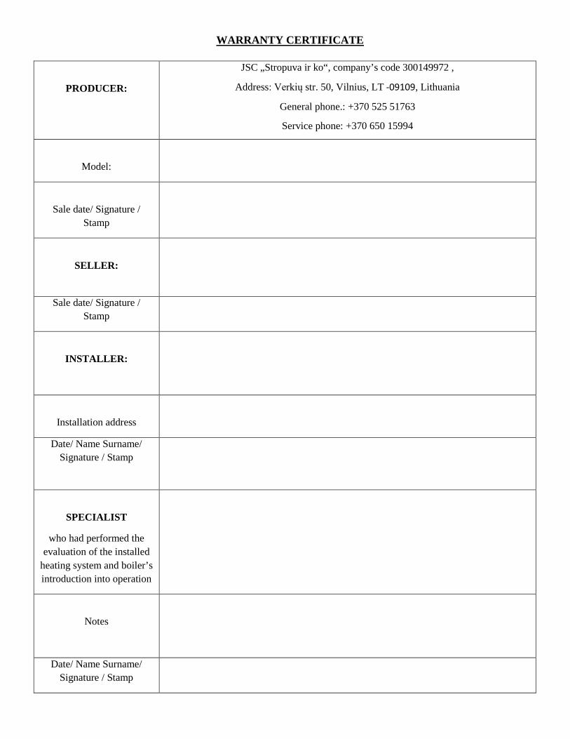
WARRANTY CERTIFICATE
PRODUCER:
JSC „Stropuva ir ko“, company’s code 300149972 ,
Address: Verkių str. 50, Vilnius, LT -09109, Lithuania
General phone.: +370 525 51763
Service phone: +370 650 15994
Model:
Sale date/ Signature / Stamp
SELLER:
Sale date/ Signature / Stamp
INSTALLER:
Installation address
Date/ Name Surname/ Signature / Stamp
SPECIALIST
who had performed the evaluation of the installed
heating system and boiler’s introduction into operation
Notes
Date/ Name Surname/ Signature / Stamp
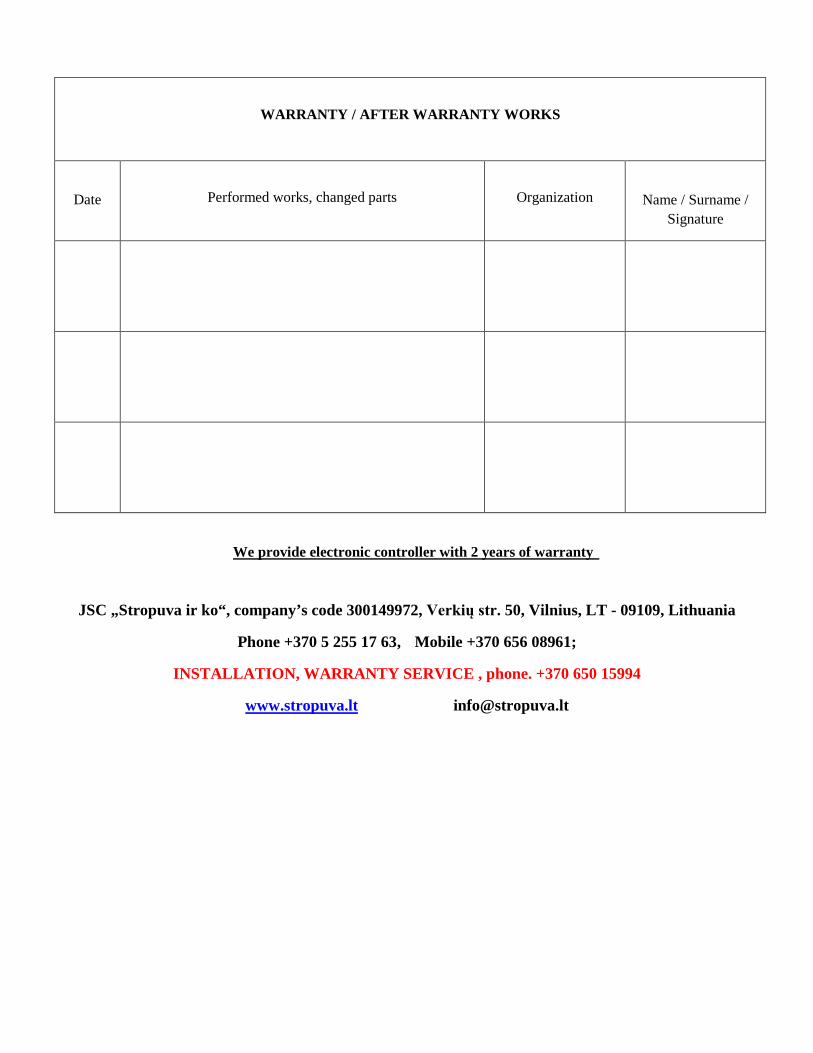
WARRANTY / AFTER WARRANTY WORKS
Date
Performed works, changed parts
Organization
Name / Surname / Signature
We provide electronic controller with 2 years of warranty
JSC „Stropuva ir ko“, company’s code 300149972, Verkių str. 50, Vilnius, LT - 09109, Lithuania
Phone +370 5 255 17 63, Mobile +370 656 08961;
INSTALLATION, WARRANTY SERVICE , phone. +370 650 15994
www.stropuva.lt [email protected]