
Contactless thin adaptive mirror technology: past, present and
14
Contactless thin adaptive mirror technology: past, present and future Roberto Biasi a , Daniele Gallieni b Piero Salinari c , Armando Riccardi c Paolo Mantegazza d a Microgate S.r.l. – Italy b A.D.S. International S.r.l. - Italy c Osservatorio Astrofisico di Arcetri - Italy d Dipartimento di ingegneria aerospaziale - Politecnico di Milano - Italy ABSTRACT The contactless, voice coil motor adaptive mirror technology starts from an idea by Piero Salinari in 1993. This idea has progressively evolved to real systems thanks to a fruitful collaboration involving Italian research institutes (INAF – Osservatorio Astrofisico di Arcetri and Aerospace Department of Politecnico di Milano) and small Italian enterprises (Microgate and ADS). Collaboration between research institutions and industry is still very effectively in place, but nowadays the technology has left the initial R&D phase reaching a stage in which the whole projects are managed by the industrial entities. In this paper we present the baseline concept and its evolution, describing the main progress milestones. These are paced by the actual implementation of this idea into real systems, from MMT, to LBT, Magellan, VLT, GMT and E-ELT. The fundamental concept and layout has remained unchanged through this evolution, maintaining its intrinsic advantages: tolerance to actuators' failures, mechanical de-coupling and relaxed tolerances between correcting mirror and reference structure, large stroke, hysteresis-free behavior. Moreover, this concept has proved its expandability to very large systems with thousands of controlled d.o.f. Notwithstanding the solidity of the fundamentals, the implementation has strongly evolved from the beginning, in order to deal with the dimensional, power, maintainability and reliability constraints imposed by the increased size of the targeted systems. Keywords: adaptive optics, adaptive mirrors, deformable mirrors, adaptive secondary, voice-coil, massive control . 1 INTRODUCTION The voice-coil based, contactless adaptive mirror has been conceived by Piero Salinari in 1993 [1]. His main goal was the development of an adaptive secondary for the Large Binocular Telescope, but it became clearly evident that the implementation of the new idea was very challenging, setting demanding requirements on several engineering fields. In fact, this technology involves multidisciplinary skills and engineering problems, from mechanics, to electronics, control systems, mechanics, fluid-dynamics and optical manufacturing. In this paper we go though the main milestones that have accompanied the development of this technology, from the early prototypes to the current systems dedicated to the 8m-class telescopes, like LBT and VLT. We also discuss the recent advancements in the design of the adaptive units for the GMT and the E-ELT extremely large telescopes, where the intrinsic advantages of this technique are particularly evident. Finally, we analyze pros and cons of this technology and explain the development roadmap to further improve it in terms of performance, reliability and maintainability. Further author information: [email protected], +39-0471-501532
Transcript of Contactless thin adaptive mirror technology: past, present and
Contactless thin adaptive mirror technology: past, present and future
Roberto Biasi a
, Daniele Gallieni b
Piero Salinaric, Armando Riccardi
c
Paolo Mantegazza d
a Microgate S.r.l. – Italy
b A.D.S. International S.r.l. - Italy
c Osservatorio Astrofisico di Arcetri - Italy
d Dipartimento di ingegneria aerospaziale - Politecnico di Milano - Italy
ABSTRACT
The contactless, voice coil motor adaptive mirror technology starts from an idea by Piero Salinari in 1993. This idea has
progressively evolved to real systems thanks to a fruitful collaboration involving Italian research institutes (INAF –
Osservatorio Astrofisico di Arcetri and Aerospace Department of Politecnico di Milano) and small Italian enterprises
(Microgate and ADS). Collaboration between research institutions and industry is still very effectively in place, but
nowadays the technology has left the initial R&D phase reaching a stage in which the whole projects are managed by the
industrial entities. In this paper we present the baseline concept and its evolution, describing the main progress
milestones. These are paced by the actual implementation of this idea into real systems, from MMT, to LBT, Magellan,
VLT, GMT and E-ELT. The fundamental concept and layout has remained unchanged through this evolution,
maintaining its intrinsic advantages: tolerance to actuators' failures, mechanical de-coupling and relaxed tolerances
between correcting mirror and reference structure, large stroke, hysteresis-free behavior. Moreover, this concept has
proved its expandability to very large systems with thousands of controlled d.o.f. Notwithstanding the solidity of the
fundamentals, the implementation has strongly evolved from the beginning, in order to deal with the dimensional, power,
maintainability and reliability constraints imposed by the increased size of the targeted systems.
Keywords: adaptive optics, adaptive mirrors, deformable mirrors, adaptive secondary, voice-coil, massive control.
1 INTRODUCTION
The voice-coil based, contactless adaptive mirror has been conceived by Piero Salinari in 1993 [1]. His main goal was
the development of an adaptive secondary for the Large Binocular Telescope, but it became clearly evident that the
implementation of the new idea was very challenging, setting demanding requirements on several engineering fields. In
fact, this technology involves multidisciplinary skills and engineering problems, from mechanics, to electronics, control
systems, mechanics, fluid-dynamics and optical manufacturing.
In this paper we go though the main milestones that have accompanied the development of this technology, from the
early prototypes to the current systems dedicated to the 8m-class telescopes, like LBT and VLT. We also discuss the
recent advancements in the design of the adaptive units for the GMT and the E-ELT extremely large telescopes, where
the intrinsic advantages of this technique are particularly evident. Finally, we analyze pros and cons of this technology
and explain the development roadmap to further improve it in terms of performance, reliability and maintainability.
Further author information: [email protected], +39-0471-501532
2 MOTIVATION FOR LARGE ADAPTIVE MIRRORS
Large adaptive mirrors, usually implemented as the secondary mirror of the telescope, have significant advantages with
respect to other adaptive optics layouts, mainly because of the reduced number of elements in the light path. The
correction is performed on a mirror that is anyway present in the telescope. This is a clear advantage, allowing to
eliminate typically 5 additional mirror that are needed by other smaller size correctors placed at the focal plane of the
telescope. The straightforward consequence of such optimization is clearly in the increased transmission throughput.
Additionally, the backgorund emission is also reduced, with a clear benefit for infrared observation. This technology also
allows a simplified feed to the wavefront sensor, leading to a reduction of the non-common path aberration that can be
particularly advantageous for high contrast diffraction limited observation, e.g. for extra-solar planet imaging. Depending
on the conjugation of the secondary mirror, this layout is particularly suited for Ground Layer AO correction.
3 PRINCIPLE OF OPERATION
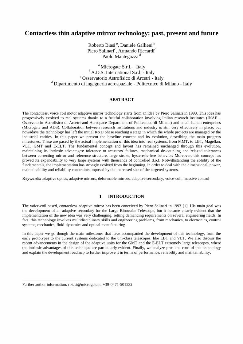
In our technology, a thin, continuous facesheet mirror is massively controlled in shape and position by a large number of
voice coil motors. These are realized by gluing high efficiency magnets on the non-optical (rear) surface of the mirror.
The actuators coils are facing the magnets, not being in contact with them. This configuration is non-optimal in terms of
reluctance of the magnetic circuit, and this affects adversely also the thermal efficiency of the motor. However, it
provides large alignment tolerances, of the order of few tenths of millimeter, on the relative position between coil and
magnet. Both the magnets and the coils have been optimized to get the maximum efficiency out of this layout.
Since we are employing force motors, but ultimately the actuators have to be commanded in position, we need a
measurement of the shell position, co-located with the actuator. This information is provided by contactless capacitive
sensors measuring the gap between the thin shell and the massive and stiff reference body. The digital control loop is
implemented by means of a high throughput, dedicated mixed signal electronics places very close to the mirror assembly.
This is required both by noise pick-up and signal integrity considerations, but also allows a great simplification of the
cable harnessing, providing a very simple data and power system interface.
Figure 1 – Main system components and principle of operation.
3.1 Control System
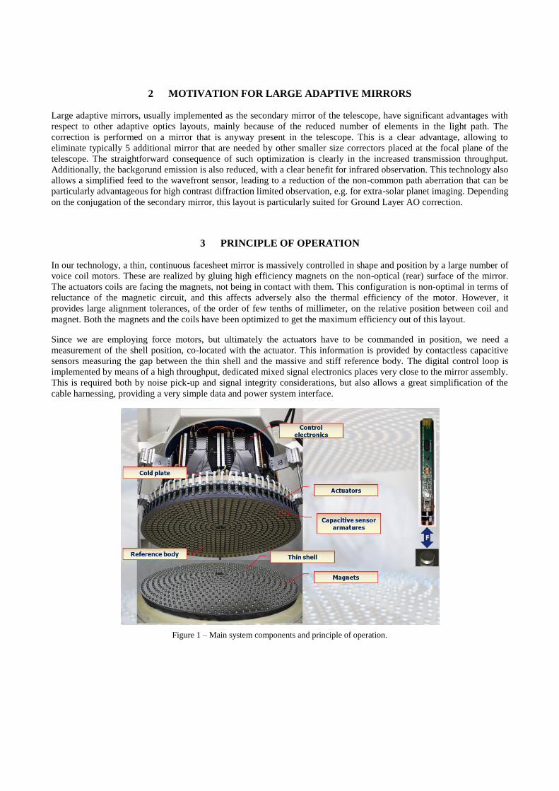
Turning the force actuators into position ones requires to close a position loop. This is obtained by means of a co-located
control scheme: the position command for the specific actuator is received from the Real Time Reconstructor (RTC) and
compared with the reading of the capacitive sensor that measures the gap between shell and reference body. The derived
error information is fed into a proportional controller. An additional velocity loop provides the damping required to
mitigate the effect of high frequency (uncontrolled) modes. In fact, the shell can be considered as an highly coupled
mechanical system with a very large modal density. Cancellation techniques are not applicable because of this large
density, and a full global scheme appears to be challenging even with modern computational power, due to the large
information exchange required. Therefore, a local digital control is the most convenient solution. The adopted control
loop frequency, of the order of 70~100kHz, together with the bandwidth of the other components, in particular capacitive
sensor and coil current drive, provide the band required to avoid high frequency spillover.
Figure 2 – Control system block diagram
The proportional gain is limited by the closed loop stability, so in order to increase the dynamic response and also to
minimize the regime error for stiff modes, a global feedforward technique is used. The forces required to set statically the
shell to the commanded shape are computed every time the position command is updated and added to the closed loop
control forces. This requires an accurate estimate of the 'stiffness' matrix relating the actuator forces to the gap
measurements. Such acquisition is performed off-line and has proved to be very stable over time. The real-time
computation of the forces is a quite heavy task, being of the order of n2, where n is the number of actuators controlling a
single shell, and considering that the computation has to be completed within 100~150µs including data transfer.
4 DEVELOPMENT HISTORY AND MAIN PAST/PRESENT PROJECTS
The idea by P.Salinari in 1993 triggered a number of parallel design and numerical simulation activities to address the
challenging problem of massive magnetic levitation. In this frame, the group that is still now carrying ahead the project
started to team up: Osservatorio di Arcetri for all conceptual, system and scientific advisory aspects, Aerospace
Department of Politecnico di Milano dealing with control laws design and simulation, and the small industrial partners
Microgate and ADS being responsible for electronics and mechanics design and implementation respectively.
4.1 Early prototypes
A very effective brainstorming among the group partners lead to define the above described system layout, that has
remained substantially unchanged from the beginning. To prove the encouraging simulation results, we started building a
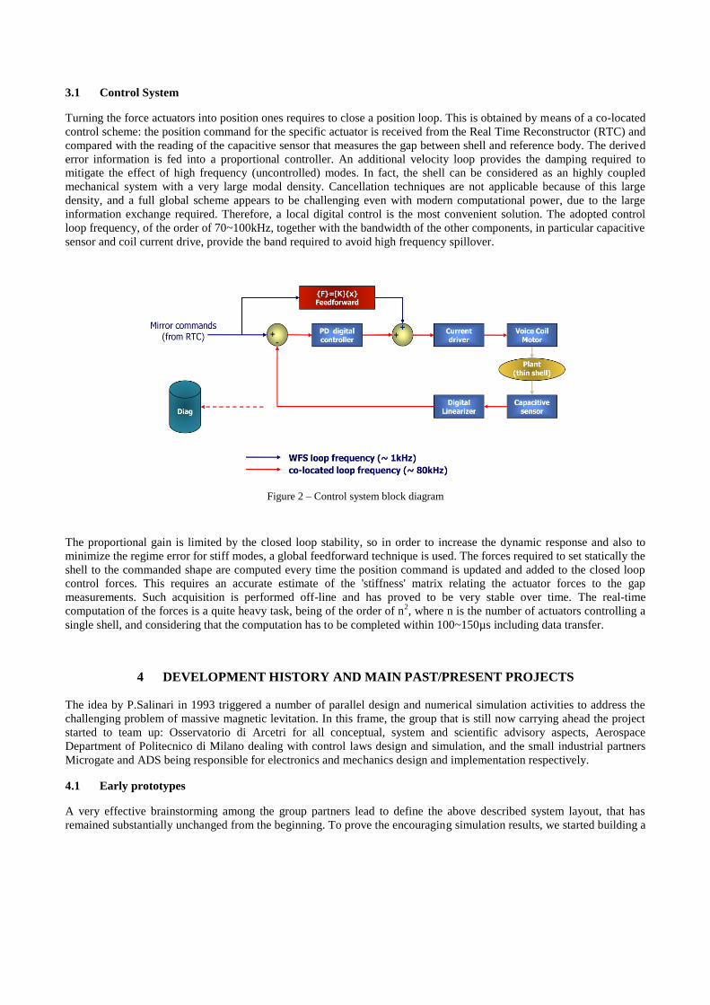
very basic prototype with thirty actuators, called P30. It was aimed to proof the concept at minimal cost, and the goal
was well reached: it was possible to flatten the shell (made by Steward Observatory Mirror Lab) under an interferometer
and also to show the dynamic capability of the novel technology. The study was conducted in a competitive way, with a
second prototype being built by an US company, but the results obtained by the Italian group were significantly better.
On this base, the University of Arizona granted a contract to manufacture the MMT adaptive mirror to our team, at that
time including also Media Lario Srl.
In parallel with the MMT adaptive secondary design phase, a more advanced, 36-actuators pre-production prototype
(called P36) was built to test all major components. In 1999, this unit met substantially the specifications, reaching 43nm
rms WF flattening and ~1ms settling time.
Figure 3 – P30, the first 30 actuators prototype, and P36, the pre-production prototype of the MMT adaptive secondary
4.2 MMT336 Adaptive Secondary
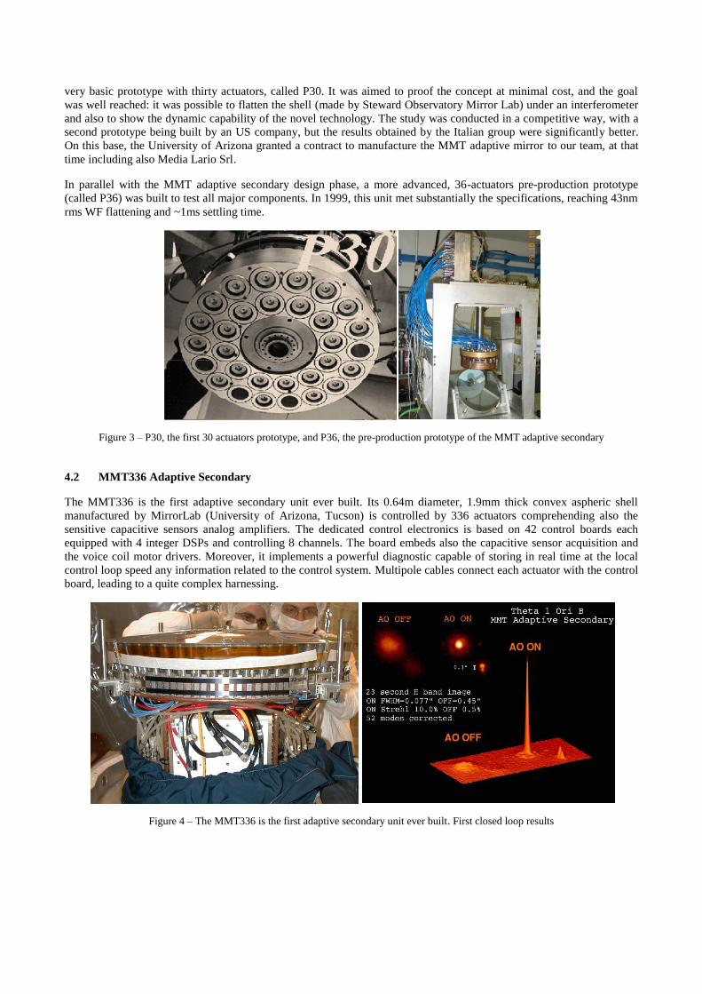
The MMT336 is the first adaptive secondary unit ever built. Its 0.64m diameter, 1.9mm thick convex aspheric shell
manufactured by MirrorLab (University of Arizona, Tucson) is controlled by 336 actuators comprehending also the
sensitive capacitive sensors analog amplifiers. The dedicated control electronics is based on 42 control boards each
equipped with 4 integer DSPs and controlling 8 channels. The board embeds also the capacitive sensor acquisition and
the voice coil motor drivers. Moreover, it implements a powerful diagnostic capable of storing in real time at the local
control loop speed any information related to the control system. Multipole cables connect each actuator with the control
board, leading to a quite complex harnessing.
Figure 4 – The MMT336 is the first adaptive secondary unit ever built. First closed loop results

The unit has been electromechanically accepted in year 2000. These electromechanical tests are a very important
verification point where all system performances, but the optical ones, are measured. This is done in a totally
autonomous way by means of the embedded metrology and diagnostic tools, so this activity does not require any external
instrument or facility, apart from an acquisition and post-processing workstation. The information derived cover all
dynamic aspects (step response, transfer function, delay error while 'playing' a simulated turbulence, ...). This
autonomous testing capability is a dramatic advantage for the project planning and deployment, providing a way of
clearly splitting the dynamic and functional tests with the optical ones.
In 2002 the unit has stated operation at the MMT on mount Hopkins, AZ. The MMT336 is still in operation and no major
operational problems are reported.
4.3 LBT672 and MMT585 Adaptive Secondary Units
After the MMT336 was finished, two identical units were built for the Large Binocular Telescope, each with 672
actuators and a 0.91m diameter, 1.6mm thick concave shell. A third almost identical unit, with a slightly smaller shell
has been integrated for the Magellan Baade telescope. Compared to the LBT adaptive secondaries, this unit does not
make use of the outermost ring of actuators. As for the MMT336, both the reference body and thin shell were
manufactured by University of Arizona Mirror Lab. While adopting exactly the same concept, these new units
implement very significant differences motivated both by 'learned lessons' on the MMT and by different system
requirements:
new actuator mounting, with accessibility from the shell side, and significantly easier actuator
mounting/dismounting. The front side accessibility has been chosen assuming that the replacement of any failed
actuator can be postponed until the next planned maintenance activity requiring the shell removal. This is made
possible by the fact that the system, thanks to its contactless technology, is very well tolerant to the failure of
few actuators, up to some percent;
distribution boards concept: printed circuit boards installed on the top of the cold plate distribute the actuators
signals so that the connection to the DSP control boards is made by flat cables grouping eight actuators each.
This provided a dramatic simplification of the cable harness and improvement of system maintainability;
new electronics and in particular DSP control boards. The new boards are equipped with two powerful floating
point DSPs, for a total computational power exceeding 80 GMAC/s in floating point, sustained. This has been
required by the demanded global control computational throughput, but allowed a very efficient on-board
implementation of the Real Time Reconstructor, with MIMO IIR filtering capabilities up to 2 poles and 2 zeros;
more efficient permanent magnets, with polarization of their field on the coil size given by a central axially
polarized magnet (not present in the MMT336 design) added to the eight radial polarized petals glued around it;
bias magnets were introduced in order to keep the shell against the reference body when the system is not
operated. Moreover, a Thin Shell Safety system pulls actively the shell with higher force when the control loop
is not closed in presence of strong wind, that could eventually pull the shell apart from the reference body.
All these new features were extensively tested on a pre-production unit with 45 actuators, called P45, before starting the
manufacturing and integration of the final units.

Figure 5 – Left: P45, the pre-production prototype for the LBT adaptive secondary mirrors. Right: the first LBT672 unit
The first LBT672 has been installed on the telescope in March 2010, after extensive optical testing [10]. In June 2010,
the adaptive secondary in combination with the novel Pyramid wavefront sensor, obtained astonishing first light results
[9].
The second LBT672 is now in the optical test phase and is planned to be installed at the telescope in Q4 2010, while the
Magellan unit has completed the electromechanical acceptance in June 2010 and will start optical tests in Q3 2010.
Figure 6 – LBT672 reflected by one of the LBT primaries and First Light Adaptive Optics (FLAO) 80% Strehl image in H
4.4 VLT Deformable Secondary Mirror
The VLT Deformable Secondary Mirror, being one of the major components of the ESO Adaptive Optics Facility [8],
has started the Manufacturing, Assembly, Integration and Test phase in February 2008, with Microgate and ADS
(respectively prime contractor and nominated subcontractor) endorsing the full responsibility of the manufacturing and
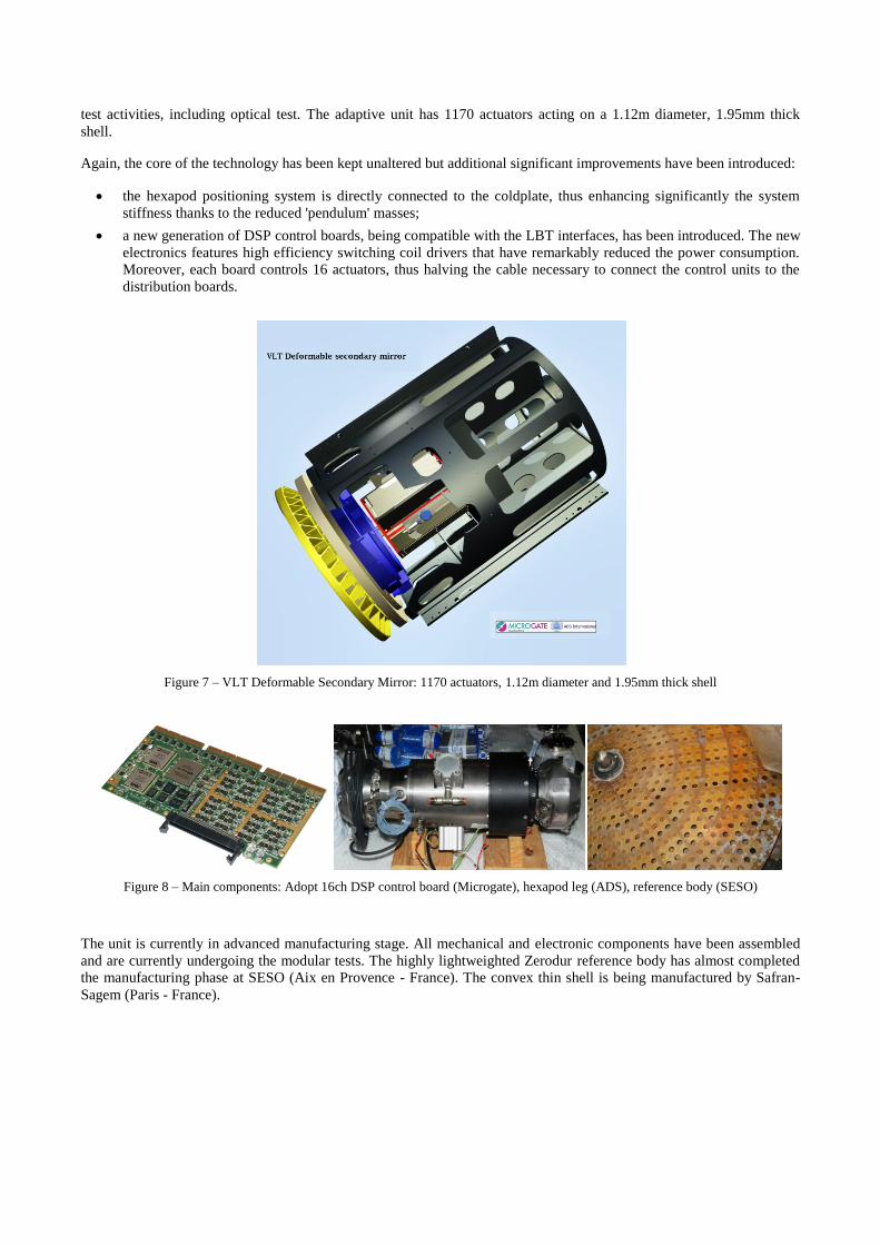
test activities, including optical test. The adaptive unit has 1170 actuators acting on a 1.12m diameter, 1.95mm thick
shell.
Again, the core of the technology has been kept unaltered but additional significant improvements have been introduced:
the hexapod positioning system is directly connected to the coldplate, thus enhancing significantly the system
stiffness thanks to the reduced 'pendulum' masses;
a new generation of DSP control boards, being compatible with the LBT interfaces, has been introduced. The new
electronics features high efficiency switching coil drivers that have remarkably reduced the power consumption.
Moreover, each board controls 16 actuators, thus halving the cable necessary to connect the control units to the
distribution boards.
Figure 7 – VLT Deformable Secondary Mirror: 1170 actuators, 1.12m diameter and 1.95mm thick shell
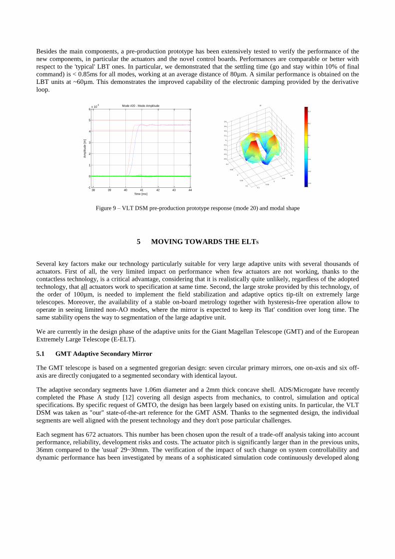
Figure 8 – Main components: Adopt 16ch DSP control board (Microgate), hexapod leg (ADS), reference body (SESO)
The unit is currently in advanced manufacturing stage. All mechanical and electronic components have been assembled
and are currently undergoing the modular tests. The highly lightweighted Zerodur reference body has almost completed
the manufacturing phase at SESO (Aix en Provence - France). The convex thin shell is being manufactured by Safran-
Sagem (Paris - France).
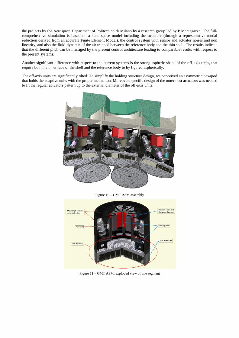
Besides the main components, a pre-production prototype has been extensively tested to verify the performance of the
new components, in particular the actuators and the novel control boards. Performances are comparable or better with
respect to the 'typical' LBT ones. In particular, we demonstrated that the settling time (go and stay within 10% of final
command) is < 0.85ms for all modes, working at an average distance of 80µm. A similar performance is obtained on the
LBT units at ~60µm. This demonstrates the improved capability of the electronic damping provided by the derivative
loop.
Figure 9 – VLT DSM pre-production prototype response (mode 20) and modal shape
5 MOVING TOWARDS THE ELTS
Several key factors make our technology particularly suitable for very large adaptive units with several thousands of
actuators. First of all, the very limited impact on performance when few actuators are not working, thanks to the
contactless technology, is a critical advantage, considering that it is realistically quite unlikely, regardless of the adopted
technology, that all actuators work to specification at same time. Second, the large stroke provided by this technology, of
the order of 100µm, is needed to implement the field stabilization and adaptive optics tip-tilt on extremely large
telescopes. Moreover, the availability of a stable on-board metrology together with hysteresis-free operation allow to
operate in seeing limited non-AO modes, where the mirror is expected to keep its 'flat' condition over long time. The
same stability opens the way to segmentation of the large adaptive unit.
We are currently in the design phase of the adaptive units for the Giant Magellan Telescope (GMT) and of the European
Extremely Large Telescope (E-ELT).
5.1 GMT Adaptive Secondary Mirror
The GMT telescope is based on a segmented gregorian design: seven circular primary mirrors, one on-axis and six off-
axis are directly conjugated to a segmented secondary with identical layout.
The adaptive secondary segments have 1.06m diameter and a 2mm thick concave shell. ADS/Microgate have recently
completed the Phase A study [12] covering all design aspects from mechanics, to control, simulation and optical
specifications. By specific request of GMTO, the design has been largely based on existing units. In particular, the VLT
DSM was taken as "our" state-of-the-art reference for the GMT ASM. Thanks to the segmented design, the individual
segments are well aligned with the present technology and they don't pose particular challenges.
Each segment has 672 actuators. This number has been chosen upon the result of a trade-off analysis taking into account
performance, reliability, development risks and costs. The actuator pitch is significantly larger than in the previous units,
36mm compared to the 'usual' 29~30mm. The verification of the impact of such change on system controllability and
dynamic performance has been investigated by means of a sophisticated simulation code continuously developed along
38 39 40 41 42 43 44-1
0
1
2
3
4
5
6x 10
-6 Mode #20 - Mode Amplitude
Time [ms]
Am
plit
ude [
m]
-0.1
-0.05
0
0.05
0.1-0.1
-0.05
0
0.05
0.1
-0.4
-0.3
-0.2
-0.1
0
0.1
0.2
0.3
0.4
20
-0.3
-0.2
-0.1
0
0.1
0.2
0.3
the projects by the Aerospace Department of Politecnico di Milano by a research group led by P.Mantegazza. The full-
comprehensive simulation is based on a state space model including the structure (through a representative modal
reduction derived from an accurate Finite Element Model), the control system with sensor and actuator noises and non
linearity, and also the fluid-dynamic of the air trapped between the reference body and the thin shell. The results indicate
that the different pitch can be managed by the present control architecture leading to comparable results with respect to
the present systems.
Another significant difference with respect to the current systems is the strong aspheric shape of the off-axis units, that
require both the inner face of the shell and the reference body to by figured aspherically.
The off-axis units are significantly tilted. To simplify the holding structure design, we conceived an asymmetric hexapod
that holds the adaptive units with the proper inclination. Moreover, specific design of the outermost actuators was needed
to fit the regular actuators pattern up to the external diameter of the off-axis units.
Figure 10 – GMT ASM assembly
Figure 11 – GMT ASM: exploded view of one segment
5.2 E-ELT M4 Adaptive Unit
In the frame of the E-ELT design, ESO has assigned two identical competitive contracts for the Phase B study of the M4
adaptive unit. One of the contracts has been granted to a group led by Microgate with ADS, Safran-Sagem and Istituto
Nazionale di Astrofisica - Osservatorio di Brera being partners of the design team.
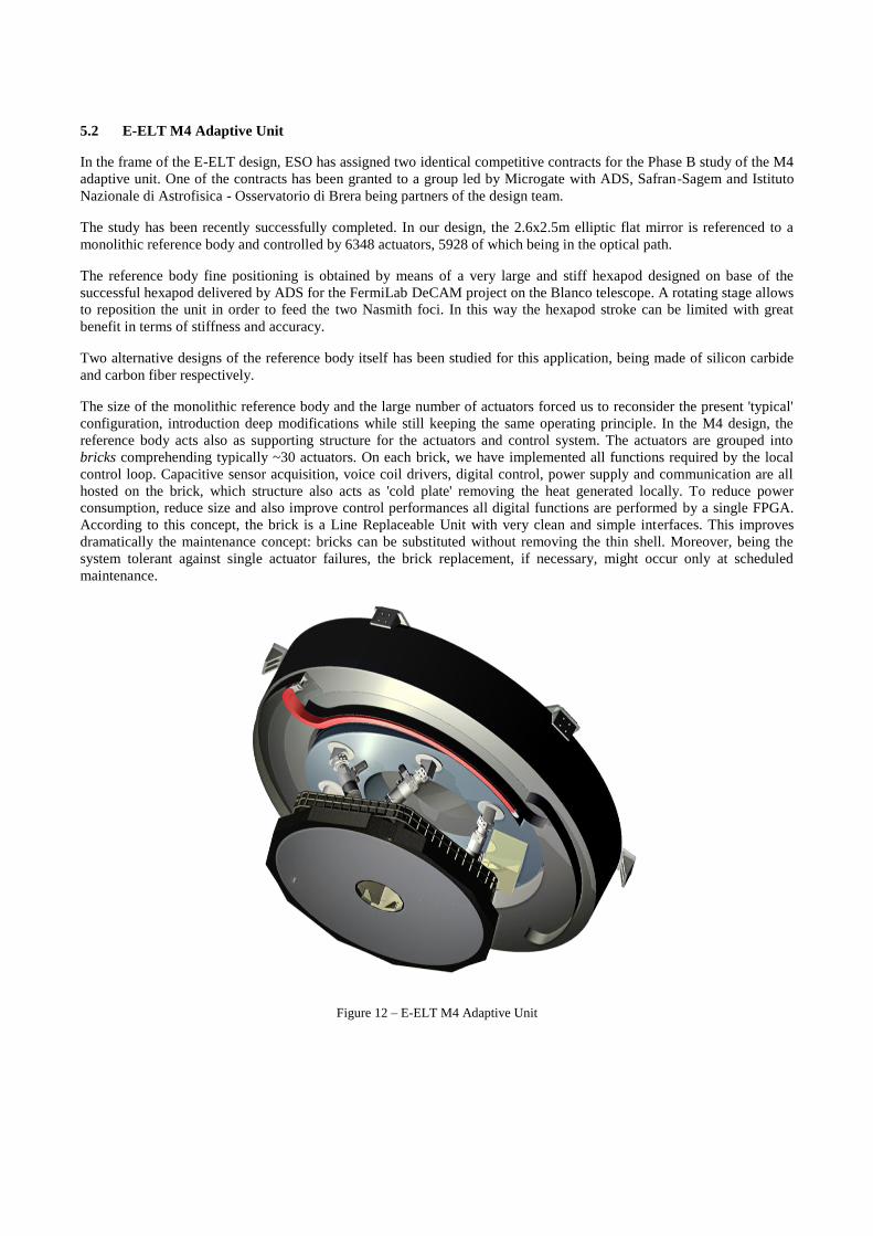
The study has been recently successfully completed. In our design, the 2.6x2.5m elliptic flat mirror is referenced to a
monolithic reference body and controlled by 6348 actuators, 5928 of which being in the optical path.
The reference body fine positioning is obtained by means of a very large and stiff hexapod designed on base of the
successful hexapod delivered by ADS for the FermiLab DeCAM project on the Blanco telescope. A rotating stage allows
to reposition the unit in order to feed the two Nasmith foci. In this way the hexapod stroke can be limited with great
benefit in terms of stiffness and accuracy.
Two alternative designs of the reference body itself has been studied for this application, being made of silicon carbide
and carbon fiber respectively.
The size of the monolithic reference body and the large number of actuators forced us to reconsider the present 'typical'
configuration, introduction deep modifications while still keeping the same operating principle. In the M4 design, the
reference body acts also as supporting structure for the actuators and control system. The actuators are grouped into
bricks comprehending typically ~30 actuators. On each brick, we have implemented all functions required by the local
control loop. Capacitive sensor acquisition, voice coil drivers, digital control, power supply and communication are all
hosted on the brick, which structure also acts as 'cold plate' removing the heat generated locally. To reduce power
consumption, reduce size and also improve control performances all digital functions are performed by a single FPGA.
According to this concept, the brick is a Line Replaceable Unit with very clean and simple interfaces. This improves
dramatically the maintenance concept: bricks can be substituted without removing the thin shell. Moreover, being the
system tolerant against single actuator failures, the brick replacement, if necessary, might occur only at scheduled
maintenance.
Figure 12 – E-ELT M4 Adaptive Unit
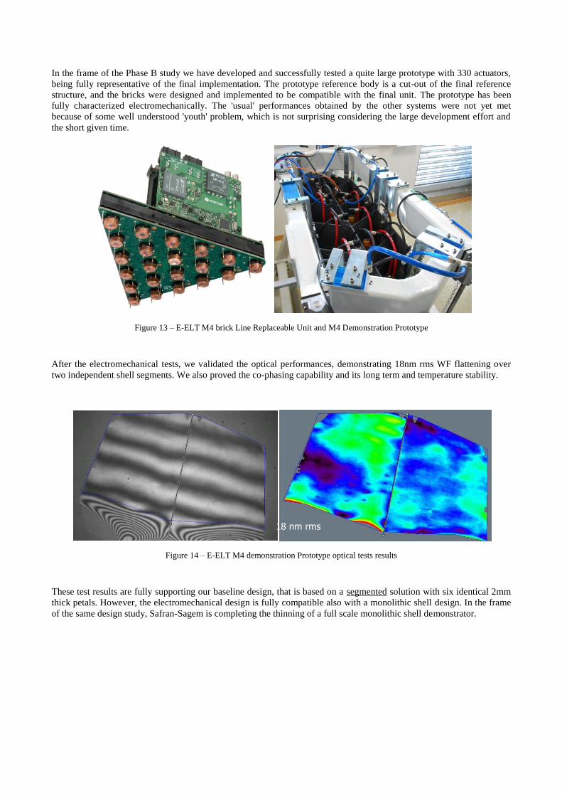
In the frame of the Phase B study we have developed and successfully tested a quite large prototype with 330 actuators,
being fully representative of the final implementation. The prototype reference body is a cut-out of the final reference
structure, and the bricks were designed and implemented to be compatible with the final unit. The prototype has been
fully characterized electromechanically. The 'usual' performances obtained by the other systems were not yet met
because of some well understood 'youth' problem, which is not surprising considering the large development effort and
the short given time.
Figure 13 – E-ELT M4 brick Line Replaceable Unit and M4 Demonstration Prototype
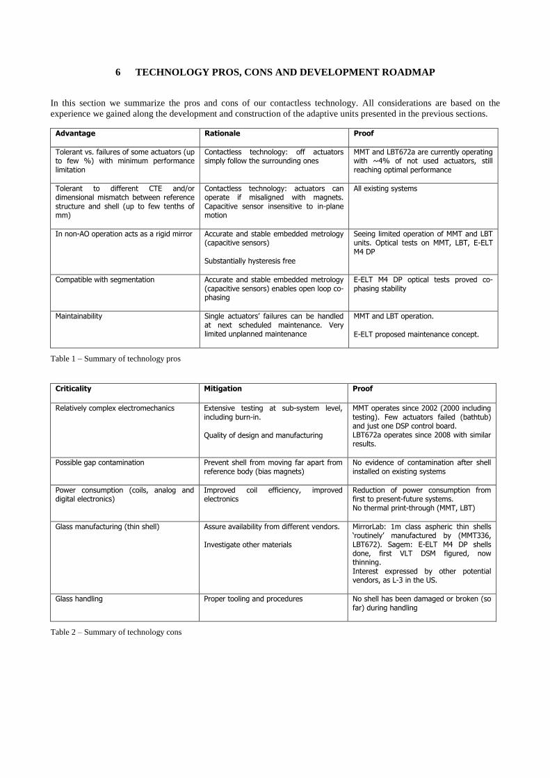
After the electromechanical tests, we validated the optical performances, demonstrating 18nm rms WF flattening over
two independent shell segments. We also proved the co-phasing capability and its long term and temperature stability.
Figure 14 – E-ELT M4 demonstration Prototype optical tests results
These test results are fully supporting our baseline design, that is based on a segmented solution with six identical 2mm
thick petals. However, the electromechanical design is fully compatible also with a monolithic shell design. In the frame
of the same design study, Safran-Sagem is completing the thinning of a full scale monolithic shell demonstrator.
18 nm rms
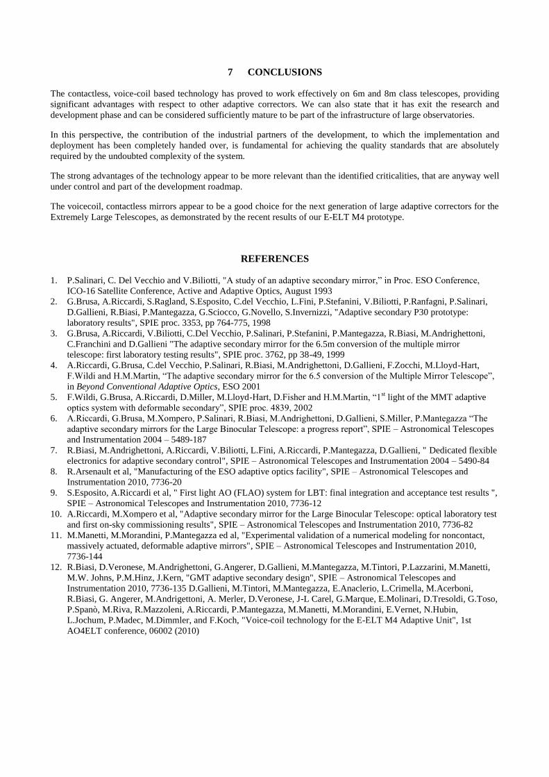
6 TECHNOLOGY PROS, CONS AND DEVELOPMENT ROADMAP
In this section we summarize the pros and cons of our contactless technology. All considerations are based on the
experience we gained along the development and construction of the adaptive units presented in the previous sections.
Advantage Rationale Proof
Tolerant vs. failures of some actuators (up to few %) with minimum performance limitation
Contactless technology: off actuators simply follow the surrounding ones
MMT and LBT672a are currently operating with ~4% of not used actuators, still reaching optimal performance
Tolerant to different CTE and/or dimensional mismatch between reference structure and shell (up to few tenths of mm)
Contactless technology: actuators can operate if misaligned with magnets. Capacitive sensor insensitive to in-plane motion
All existing systems
In non-AO operation acts as a rigid mirror Accurate and stable embedded metrology (capacitive sensors)
Substantially hysteresis free
Seeing limited operation of MMT and LBT units. Optical tests on MMT, LBT, E-ELT M4 DP
Compatible with segmentation Accurate and stable embedded metrology (capacitive sensors) enables open loop co-phasing
E-ELT M4 DP optical tests proved co-phasing stability
Maintainability Single actuators’ failures can be handled at next scheduled maintenance. Very limited unplanned maintenance
MMT and LBT operation.
E-ELT proposed maintenance concept.
Table 1 – Summary of technology pros
Criticality Mitigation Proof
Relatively complex electromechanics Extensive testing at sub-system level, including burn-in.
Quality of design and manufacturing
MMT operates since 2002 (2000 including testing). Few actuators failed (bathtub) and just one DSP control board. LBT672a operates since 2008 with similar results.
Possible gap contamination Prevent shell from moving far apart from reference body (bias magnets)
No evidence of contamination after shell installed on existing systems
Power consumption (coils, analog and digital electronics)
Improved coil efficiency, improved electronics
Reduction of power consumption from first to present-future systems. No thermal print-through (MMT, LBT)
Glass manufacturing (thin shell) Assure availability from different vendors.
Investigate other materials
MirrorLab: 1m class aspheric thin shells ‘routinely’ manufactured by (MMT336, LBT672). Sagem: E-ELT M4 DP shells done, first VLT DSM figured, now thinning. Interest expressed by other potential vendors, as L-3 in the US.
Glass handling Proper tooling and procedures No shell has been damaged or broken (so far) during handling
Table 2 – Summary of technology cons

We clearly state that the pros of the technology are significantly more relevant than the identified criticalities, that are
well under control and have been continuously improved along the projects. To confirm this on a specific aspect, we
report in Figure 15 the advances made in terms of power consumption.
Figure 15 – Total system power consumption per actuator: evolution along the projects
Finally, we have clearly identified a development roadmap, which main goals are reported in Table 3.
Goal How to Timeframe
Further increase stroke for: - field stabilization - to relax shell-reference body matching requirements
Faster and even less noisy electronics E-ELT M4 final design –demonstrated on M4 DP with some ‘youth’ limitations
Improve thermal/long term stability for: - co-phasing - non-AO performance
Capacitive sensor mechanical/electrostatic design
E-ELT M4 final design –demonstrated on M4 DP
Reduction of power consumption through further improvement of coil efficiency and current drive efficiency
Improved magnets, alternative EM design, more efficient drive electronics
Major step from LBT to VLT. Following technology improvements
Alternative reference body materials, especially for units beyond 1m class
Investigate silicon carbide and carbon fiber Analysis ongoing within E-ELT M4 design. Silicon carbide tested on E-ELT M4 DP
Improved control techniques Collaboration with Politecnico di Milano – Dipartimento di Ingeneria Aerospaziale. Sophisticated simulation tool.
Ongoing, to be applied on GMT and E-ELT M4. If confirmed by results, the improvement can be applied to LBT and VLT
Alternative thin shell materials Microgate/ADS joined effort with CMA (Tucson-AZ) to make a carbon fiber thin shell
Ongoing on small scale prototype that provided encouraging dynamic response results
Table 3 – Development roadmap
MMT336
LBT672
VLT DSM GMT ASM
GMT ASM splitE-ELT M4
0,0
0,5
1,0
1,5
2,0
2,5
3,0
3,5P
ow
er
[W/a
ct]
7 CONCLUSIONS
The contactless, voice-coil based technology has proved to work effectively on 6m and 8m class telescopes, providing
significant advantages with respect to other adaptive correctors. We can also state that it has exit the research and
development phase and can be considered sufficiently mature to be part of the infrastructure of large observatories.
In this perspective, the contribution of the industrial partners of the development, to which the implementation and
deployment has been completely handed over, is fundamental for achieving the quality standards that are absolutely
required by the undoubted complexity of the system.
The strong advantages of the technology appear to be more relevant than the identified criticalities, that are anyway well
under control and part of the development roadmap.
The voicecoil, contactless mirrors appear to be a good choice for the next generation of large adaptive correctors for the
Extremely Large Telescopes, as demonstrated by the recent results of our E-ELT M4 prototype.
REFERENCES
1. P.Salinari, C. Del Vecchio and V.Biliotti, "A study of an adaptive secondary mirror,” in Proc. ESO Conference,
ICO-16 Satellite Conference, Active and Adaptive Optics, August 1993
2. G.Brusa, A.Riccardi, S.Ragland, S.Esposito, C.del Vecchio, L.Fini, P.Stefanini, V.Biliotti, P.Ranfagni, P.Salinari,
D.Gallieni, R.Biasi, P.Mantegazza, G.Sciocco, G.Novello, S.Invernizzi, "Adaptive secondary P30 prototype:
laboratory results", SPIE proc. 3353, pp 764-775, 1998
3. G.Brusa, A.Riccardi, V.Biliotti, C.Del Vecchio, P.Salinari, P.Stefanini, P.Mantegazza, R.Biasi, M.Andrighettoni,
C.Franchini and D.Gallieni "The adaptive secondary mirror for the 6.5m conversion of the multiple mirror
telescope: first laboratory testing results", SPIE proc. 3762, pp 38-49, 1999
4. A.Riccardi, G.Brusa, C.del Vecchio, P.Salinari, R.Biasi, M.Andrighettoni, D.Gallieni, F.Zocchi, M.Lloyd-Hart,
F.Wildi and H.M.Martin, “The adaptive secondary mirror for the 6.5 conversion of the Multiple Mirror Telescope”,
in Beyond Conventional Adaptive Optics, ESO 2001
5. F.Wildi, G.Brusa, A.Riccardi, D.Miller, M.Lloyd-Hart, D.Fisher and H.M.Martin, “1st light of the MMT adaptive
optics system with deformable secondary”, SPIE proc. 4839, 2002
6. A.Riccardi, G.Brusa, M.Xompero, P.Salinari, R.Biasi, M.Andrighettoni, D.Gallieni, S.Miller, P.Mantegazza “The
adaptive secondary mirrors for the Large Binocular Telescope: a progress report”, SPIE – Astronomical Telescopes
and Instrumentation 2004 – 5489-187
7. R.Biasi, M.Andrighettoni, A.Riccardi, V.Biliotti, L.Fini, A.Riccardi, P.Mantegazza, D.Gallieni, " Dedicated flexible
electronics for adaptive secondary control", SPIE – Astronomical Telescopes and Instrumentation 2004 – 5490-84
8. R.Arsenault et al, "Manufacturing of the ESO adaptive optics facility", SPIE – Astronomical Telescopes and
Instrumentation 2010, 7736-20
9. S.Esposito, A.Riccardi et al, " First light AO (FLAO) system for LBT: final integration and acceptance test results ",
SPIE – Astronomical Telescopes and Instrumentation 2010, 7736-12
10. A.Riccardi, M.Xompero et al, "Adaptive secondary mirror for the Large Binocular Telescope: optical laboratory test
and first on-sky commissioning results", SPIE – Astronomical Telescopes and Instrumentation 2010, 7736-82
11. M.Manetti, M.Morandini, P.Mantegazza ed al, "Experimental validation of a numerical modeling for noncontact,
massively actuated, deformable adaptive mirrors", SPIE – Astronomical Telescopes and Instrumentation 2010,
7736-144
12. R.Biasi, D.Veronese, M.Andrighettoni, G.Angerer, D.Gallieni, M.Mantegazza, M.Tintori, P.Lazzarini, M.Manetti,
M.W. Johns, P.M.Hinz, J.Kern, "GMT adaptive secondary design", SPIE – Astronomical Telescopes and
Instrumentation 2010, 7736-135 D.Gallieni, M.Tintori, M.Mantegazza, E.Anaclerio, L.Crimella, M.Acerboni,
R.Biasi, G. Angerer, M.Andrigettoni, A. Merler, D.Veronese, J-L Carel, G.Marque, E.Molinari, D.Tresoldi, G.Toso,
P.Spanò, M.Riva, R.Mazzoleni, A.Riccardi, P.Mantegazza, M.Manetti, M.Morandini, E.Vernet, N.Hubin,
L.Jochum, P.Madec, M.Dimmler, and F.Koch, "Voice-coil technology for the E-ELT M4 Adaptive Unit", 1st
AO4ELT conference, 06002 (2010)