
Construction and Testing of GFRP Steel Hybrid-Reinforced ... · Construction and Testing of GFRP...
11
Construction and Testing of GFRP Steel Hybrid-Reinforced Concrete Bridge-Deck Slabs of Sainte-Catherine Overpass Bridges Ehab A. Ahmed, M.ASCE 1 ; François Settecasi 2 ; and Brahim Benmokrane 3 Abstract: Hybrid reinforcement for concrete bridge-deck slabs is being investigated through a collaboration project between the Ministry of Transportation of Quebec (MTQ) and the University of Sherbrooke. This paper presents design concepts, construction details, and results of live-load field tests of the twin hybrid-reinforced bridges (P-15502N and P-15502S) on Sainte Catherine Road in Sherbrooke, Quebec (Canada). These hybrid-reinforced slab-on-girder bridges are simply supported over a single span of 43,415 mm. Their 200-mm-thick concrete deck slabs are continuous over four spans of 2,650 mm each, with an average overhang of about 1,000 mm on both sides (measured perpendicular to the girder axis). The deck slabs were reinforced with glass fiber–reinforced polymer (GFRP) reinforcing bars in the top mat and with galvanized steel bars in the bottom mat. One of the two bridges (P-15502S) was instrumented with fiber-optic sensors (FOSs) in the bridge-deck slab (over and between the girders). The instrumented bridge was tested for service performance with three calibrated truck loads prior to placement of the asphalt layer to check for flexural cracks. The construction details and the results of the live-load field tests are presented. The field tests yielded very small strains in the GFRP reinforcing bars, which clarified the arch-action effect in the restrained hybrid-RC bridge decks. DOI: 10.1061/ (ASCE)BE.1943-5592.0000581. © 2014 American Society of Civil Engineers. Author keywords: Bridges; Concrete; Bridge decks; Highway; Fiber-reinforced polymer (FRP); Glass fibers; Reinforcement; Field tests; Strain; Deflection; Arch action; Monitoring. Introduction Most RC bridges in Canada are of slab-on-girder type. The deck slabs of these bridges are reinforced with two mats (top and bottom) and connected to the supporting girders with shear connectors (studs). Because of the harsh environmental conditions and the excessive use of deicing salts in the winter, the steel-reinforced concrete bridge-deck slabs exhibit steel corrosion and consequent deterioration. The costs of the repairs and related problems, such as delaying and detouring traffic, have provided an impetus to use noncorrosive fiber-reinforced- polymer (FRP) bars as an alternative reinforcement. Since 1992, significant efforts have been made in Canada to significantly change the design and construction of bridge structures by developing innovative structures incorporating FRPs, fiber-optic sensors (FOSs), and structural health monitoring (SHM) (Mufti and Neale 2007). The Structures Division of the Ministry of Trans- portation of Quebec (MTQ), since the late 1990s, has been interested in building bridges with an extended service life of 75–150 years. These durable bridges can be built by employing noncorroding FRP reinforcing bars as the main reinforcement for the concrete bridge decks. Based on this technique, the MTQ has carried out, in col- laboration with the University of Sherbrooke (Sherbrooke, Quebec), several research projects using FRP reinforcement in concrete bridge-deck slabs under static and fatigue loadings (El-Gamal et al. 2005, 2007; El-Ragaby et al. 2007a, b) and bridge barriers under static and impact loadings (El-Salakawy et al. 2003a, 2004; Ahmed and Benmokrane 2011; Ahmed et al. 2013). Moreover, several demonstration field applications have been carried out in Quebec, such as the Joffre Bridge in Sherbrooke, the Wotton Bridge in Wotton, the Magog Bridge on Highway 55 North, the Cookshire- Eaton Bridge on Route 108, and the Val-Alain Bridge on Highway 20 East (El-Salakawy and Benmokrane 2003; El-Salakawy et al. 2003b, 2005; Benmokrane et al. 2004, 2007), and in the United States, such as Morristown Bridge in Vermont (Benmokrane et al. 2006) and the bridges located at Pierce Street in Lima (Ohio 1999), Salem Avenue in Dayton (Ohio 1999), Rollins Road in Rollinsford (New Hampshire 2000), Sierrita de la Cruz Creek in Potter County (Texas 2000); 53rd Avenue in Bettendorf (Iowa 2001), Bridge Street in Southfield (Michigan 2001), Highway 151 in Waupun (Wisconsin 2005), and Route Y in Boone County (Missouri 2007) (Eamon et al. 2012). Most of these projects focused on the use of the glass-FRP (GFRP) bars because of their relatively lower cost compared with that of other FRPs (carbon and aramid). Some of these bridges have been in service for more than 10 years without any signs of de- terioration or unexpected problems. Furthermore, the durability of GFRP reinforcement in real RC bridges exposed to different en- vironments for 10–13 years has been investigated (Mufti et al. 2005, 2007, 2011). The investigations (Mufti et al. 2005, 2007, 2011) showed that the structure of the polymer matrix of GFRP rein- forcement was not significantly disrupted by exposure to the en- vironment. Neither hydrolysis nor significant changes in the glass 1 Postdoctoral Fellow, Dept. of Civil Engineering, Univ. of Sherbrooke, Sherbrooke, QC, Canada J1K 2R1. E-mail: [email protected] 2 Master’s Student, Dept. of Civil Engineering, Univ. of Sherbrooke, Sherbrooke, QC, Canada J1K 2R1. E-mail: francois.settecasi@usherbrooke .ca 3 Natural Sciences and Engineering Research Council (NSERC) and Tier-1 Canada Research Chair Professor in Advanced Fiber-Reinforced Polymer Composite Materials for Civil Structures, Dept. of Civil Engineering, Univ. of Sherbrooke, Sherbrooke, QC, Canada J1K 2R1 (corresponding author). E-mail: [email protected] Note. This manuscript was submitted on May 13, 2013; approved on November 7, 2013; published online on January 10, 2014. Discussion period open until June 10, 2014; separate discussions must be submitted for individual papers. This paper is part of the Journal of Bridge Engineering, © ASCE, ISSN 1084-0702/04014011(11)/$25.00. © ASCE 04014011-1 J. Bridge Eng. J. Bridge Eng. Downloaded from ascelibrary.org by UNIVERSITE DE SHERBROOKE on 01/17/14. Copyright ASCE. For personal use only; all rights reserved.
Transcript of Construction and Testing of GFRP Steel Hybrid-Reinforced ... · Construction and Testing of GFRP...

Construction and Testing of GFRP Steel Hybrid-ReinforcedConcrete Bridge-Deck Slabs of Sainte-Catherine
Overpass BridgesEhab A. Ahmed, M.ASCE1; François Settecasi2; and Brahim Benmokrane3
Abstract: Hybrid reinforcement for concrete bridge-deck slabs is being investigated through a collaboration project between the Ministry ofTransportation of Quebec (MTQ) and the University of Sherbrooke. This paper presents design concepts, construction details, and results oflive-load field tests of the twin hybrid-reinforced bridges (P-15502N andP-15502S) on Sainte CatherineRoad in Sherbrooke, Quebec (Canada).These hybrid-reinforced slab-on-girder bridges are simply supported over a single span of 43,415mm. Their 200-mm-thick concrete deck slabsare continuous over four spans of 2,650 mm each, with an average overhang of about 1,000 mm on both sides (measured perpendicular to thegirder axis). The deck slabs were reinforced with glass fiber–reinforced polymer (GFRP) reinforcing bars in the top mat and with galvanizedsteel bars in the bottommat. One of the two bridges (P-15502S) was instrumented with fiber-optic sensors (FOSs) in the bridge-deck slab (overand between the girders). The instrumented bridge was tested for service performance with three calibrated truck loads prior to placement of theasphalt layer to check for flexural cracks. The construction details and the results of the live-load field tests are presented. The field tests yieldedvery small strains in the GFRP reinforcing bars, which clarified the arch-action effect in the restrained hybrid-RC bridge decks.DOI: 10.1061/(ASCE)BE.1943-5592.0000581. © 2014 American Society of Civil Engineers.
Author keywords: Bridges; Concrete; Bridge decks; Highway; Fiber-reinforced polymer (FRP); Glass fibers; Reinforcement; Field tests;Strain; Deflection; Arch action; Monitoring.
Introduction
Most RC bridges in Canada are of slab-on-girder type. The deckslabs of these bridges are reinforced with two mats (top and bottom)and connected to the supporting girderswith shear connectors (studs).Because of the harsh environmental conditions and the excessive useof deicing salts in thewinter, the steel-reinforced concrete bridge-deckslabs exhibit steel corrosion and consequent deterioration. The costsof the repairs and related problems, such as delaying and detouringtraffic, haveprovided an impetus to use noncorrosivefiber-reinforced-polymer (FRP) bars as an alternative reinforcement.
Since 1992, significant efforts have been made in Canada tosignificantly change the design and construction of bridge structuresby developing innovative structures incorporating FRPs, fiber-opticsensors (FOSs), and structural health monitoring (SHM) (Mufti andNeale 2007). The Structures Division of the Ministry of Trans-portation ofQuebec (MTQ), since the late 1990s, has been interestedin building bridges with an extended service life of 75–150 years.
These durable bridges can be built by employing noncorroding FRPreinforcing bars as the main reinforcement for the concrete bridgedecks. Based on this technique, the MTQ has carried out, in col-laboration with the University of Sherbrooke (Sherbrooke, Quebec),several research projects using FRP reinforcement in concretebridge-deck slabs under static and fatigue loadings (El-Gamal et al.2005, 2007; El-Ragaby et al. 2007a, b) and bridge barriers understatic and impact loadings (El-Salakawy et al. 2003a, 2004; Ahmedand Benmokrane 2011; Ahmed et al. 2013). Moreover, severaldemonstration field applications have been carried out in Quebec,such as the Joffre Bridge in Sherbrooke, the Wotton Bridge inWotton, the Magog Bridge on Highway 55 North, the Cookshire-Eaton Bridge on Route 108, and the Val-Alain Bridge on Highway20 East (El-Salakawy and Benmokrane 2003; El-Salakawy et al.2003b, 2005; Benmokrane et al. 2004, 2007), and in the UnitedStates, such as Morristown Bridge in Vermont (Benmokrane et al.2006) and the bridges located at Pierce Street in Lima (Ohio 1999),Salem Avenue in Dayton (Ohio 1999), Rollins Road in Rollinsford(New Hampshire 2000), Sierrita de la Cruz Creek in Potter County(Texas 2000); 53rdAvenue inBettendorf (Iowa 2001), Bridge Streetin Southfield (Michigan 2001), Highway 151 inWaupun (Wisconsin2005), and Route Y in Boone County (Missouri 2007) (Eamon et al.2012). Most of these projects focused on the use of the glass-FRP(GFRP) bars because of their relatively lower cost compared withthat of other FRPs (carbon and aramid). Some of these bridges havebeen in service for more than 10 years without any signs of de-terioration or unexpected problems. Furthermore, the durability ofGFRP reinforcement in real RC bridges exposed to different en-vironments for 10–13 years has been investigated (Mufti et al. 2005,2007, 2011). The investigations (Mufti et al. 2005, 2007, 2011)showed that the structure of the polymer matrix of GFRP rein-forcement was not significantly disrupted by exposure to the en-vironment. Neither hydrolysis nor significant changes in the glass
1Postdoctoral Fellow, Dept. of Civil Engineering, Univ. of Sherbrooke,Sherbrooke, QC, Canada J1K 2R1. E-mail: [email protected]
2Master’s Student, Dept. of Civil Engineering, Univ. of Sherbrooke,Sherbrooke, QC, Canada J1K 2R1. E-mail: [email protected]
3Natural Sciences and Engineering Research Council (NSERC) andTier-1 Canada Research Chair Professor in Advanced Fiber-ReinforcedPolymer Composite Materials for Civil Structures, Dept. of CivilEngineering, Univ. of Sherbrooke, Sherbrooke, QC, Canada J1K 2R1(corresponding author). E-mail: [email protected]
Note. This manuscript was submitted on May 13, 2013; approved onNovember 7, 2013; published online on January 10, 2014. Discussion periodopen until June 10, 2014; separate discussions must be submitted forindividual papers. This paper is part of the Journal of Bridge Engineering,© ASCE, ISSN 1084-0702/04014011(11)/$25.00.
© ASCE 04014011-1 J. Bridge Eng.
J. Bridge Eng.
Dow
nloa
ded
from
asc
elib
rary
.org
by
UN
IVE
RSI
TE
DE
SH
ER
BR
OO
KE
on
01/1
7/14
. Cop
yrig
ht A
SCE
. For
per
sona
l use
onl
y; a
ll ri
ghts
res
erve
d.

transition temperature of the matrix took place after exposure to thecombined effects of the concrete alkaline environment and theexternal natural environmental exposure for 10–13 years. Thesecompelling pieces of evidence presented on the durability of GFRPreinforcement encouragewider acceptance of this technology in newapplications with extended service life.
In a typical slab-on-girder concrete bridge deck, the top rein-forcing mat is closer to the concrete surface and, consequently, issusceptible to chloride and chemical exposure, which may accel-erate the corrosion of the steel bars. The bottom reinforcement mat,however, is not susceptible to such exposure. In addition, the designof these bridge decks controls crack width, which limits chloridemigration from the top surface to the bottom reinforcement layer.Thus, design engineers and municipalities proposed to use non-corrosive GFRP bars in the top reinforcement mat andmaintain steelbars in the bottom reinforcement mat (hybrid-reinforced-concretebridge-deck slabs). This technique is expected to yield durableconcrete bridge decks with cost-effective designs, because only thetop reinforcing mat is replaced with GFRP bars.
The Canadian Standards Association (CSA) (2006), whichallows the use of GFRP bars as the main reinforcement in bridge-deck slabs, provides a step forward toward the transition from re-search to commercial projects based on cost-benefit considerations.Consequently, there is a remarkable increase in the use of FRPs inbridges such asHawkLake bridge (Ontario 2008),Bridgeport bridgeandDry Sadle bridge (Ontario 2009), ShadowRiver bridge (Ontario2010), and 18th Street bridge (Manitoba 2010). The CSA (2006)provides two different design methods for the bridge-deck slabs,namely, the flexural design method and empirical method. Thesedesignmethods are for bridge-deck slabs totally reinforcedwith steelor FRP bars. The code, however, makes no provisions for the hybridreinforcement concept. Consequently, there is a need to understandhow these hybrid-reinforced-concrete bridge-deck slabs performand then to approve and integrate this concept into bridge designcodes and guidelines.
To investigate the effectiveness and durability of GFRP bars astop reinforcement for concrete decks, the Virginia Department ofTransportation (VDOT) and the Virginia Transportation ResearchCouncil (VTRC) with funding provided through the Federal High-way Administration’s (FHWA) Innovative Bridge Research andConstruction (IBRC) program worked with Virginia Tech to con-struct the Route 668 Bridge over Gills Creek in Franklin County,Virginia. The bridge was completed in July 2003. The deck of onespan was reinforced with GFRP bars for the top mat and epoxy-coated steel bars for the bottom mat. The other two spans werereinforced with epoxy-coated steel bars for the top and bottom mats(Phillips et al. 2005). Live-load tests were performed in 2003 shortlyafter the completion of construction and again in 2004. In addition,tests were performed on the deck of the opposite end-span, whichhad all epoxy-coated steel reinforcement. The performances of thetwo end-spans were compared to determine if the GFRP reinforce-ment had any significant influence on the overall bridge behaviorcompared with the epoxy-coated steel bars. Phillips et al. (2005)reported that there were no significant differences in the behavior ofthe deck after 1 year of service, and there was no visible cracking. Thebehavior of the two end-spans was similar, and the measured girderdistribution factors were less than the AASHTO design recom-mendations.Recently, theMTQinitiated an extensive researchprojectin collaboration with the University of Sherbrooke aimed at in-vestigating the structural performance of hybrid-reinforced-concretebridge decks through some new concrete bridges that are being builtalong the extension of Highway 410 (Sherbrooke, Quebec). The firstin this series was the 410 overpass on Boulevard de l’Universitéin Sherbrooke, which was built and tested in 2010 (Ahmed and
Benmokrane 2012), followed by the Sainte Catherine twin overpasses(P-15502N and P-15502S; Sherbrooke, Quebec), which wereconstructed in 2012.
This paper presents the design criteria and investigates the serviceperformance of the Sainte Catherine twin overpasses (P-15502N andP-15502S; Sherbrooke, Quebec) through a live-load field test of theP-15502S bridge, which was instrumented with FOSs. The resultsreported in this paper provide a step forward toward introducingthe hybrid-reinforcement technique to the bridge design codes andguides.
Project Description and Construction
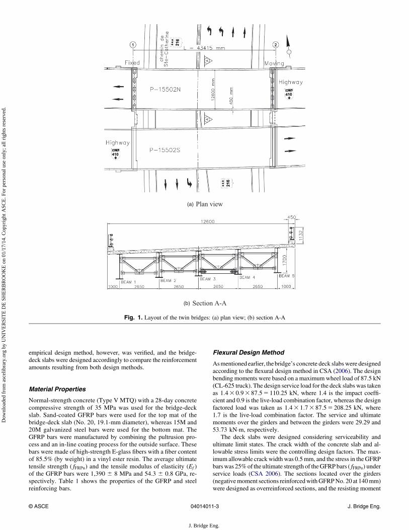
The Sainte Catherine twin overpass bridges (P-15502N and P-15502S) are located on Highway 410 in Sherbrooke, passing overSainte Catherine Road in Quebec, Canada. The project comprisestwo identical bridges (Highway 410 East and Highway 410 West)with a typical slab-on-girder structural system. Each bridge has twotraffic lanes (see layout in Fig. 1). Each bridge has five steel girderssimply supported over a single span of 43,415 mm [Fig. 2(a)]. Theconcrete deck slab is 200 mm thick [Fig. 2(b)] and continuous overfour 2,650-mm spans with an average overhang of about 10 mm oneach side (measured perpendicular to the girder axis).
The main steel girders of the two bridges are composite with theconcrete deck slab using 22-mm-diameter3 130-mm-long studconnectors. The steel girders have a constant depth of 1,700mmoverthe span. The steel girders are supported laterally using six crossframes spaced at 5,873 mm. The top mat of the concrete deck slabwas reinforced with sand-coated GFRP reinforcing bars manufac-tured by Pultrall (Thetford Mines, Quebec, Canada). The bottomreinforcing mat was made of galvanized steel bars. The side barriersof the two bridges were of MTQ 210 type (steel post and beam overa concrete curb) and were reinforced with galvanized steel bars.
The construction of the slabs of the twin overpass bridges(P-15502N and P-15502S) started on April 2012 with the setting upof the formwork for the deck slabs for the two bridges. Fig. 3 showsthe different stages of construction. Because of the lightweight of theGFRP bars, more bars were handled in less time. Plastic supportarrays spaced at 0.75 m were used to maintain bottom and topconcrete clear covers of 38 and 50 mm, respectively. Neither theGFRP bars nor the steel bars were spliced in the transverse direction.On the other hand, there were three splices with a splice length of600 mm (�30db, where db is the reinforcing bar diameter) in thelongitudinal steel bars in the bottom mat and three splices witha splice length of 960 mm (�50db) in the longitudinal GFRP bars inthe top mat. The additional GFRP bars at the overhang were placedbetween the continuous transverse top reinforcement elements andwere extended 1.4 m into the adjacent span to ensure adequatedevelopment length and moment resistance. The placement of thebottom steel reinforcement mat was completed on May 18, 2012,and the top GFRP reinforcement mat was completed on May 22,2012. The two bridge-deck slabswere cast onMay 31, 2012, startingwith the P-15502N bridge and ending with the P-15502S bridge(instrumented), which is the one being reported in this paper. Be-cause one of the project’s main objectives was to verify flexuralcracking that might occur during field testing, the P-15502S bridgewas tested before being paved. The live-loadfield test was conductedon October 30, 2012.
Design of the Bridge’s Concrete Deck Slab
The bridge-deck slabs of the two bridges were designed according tothe flexural design method in CSA (2006). The applicability of the
© ASCE 04014011-2 J. Bridge Eng.
J. Bridge Eng.
Dow
nloa
ded
from
asc
elib
rary
.org
by
UN
IVE
RSI
TE
DE
SH
ER
BR
OO
KE
on
01/1
7/14
. Cop
yrig
ht A
SCE
. For
per
sona
l use
onl
y; a
ll ri
ghts
res
erve
d.
empirical design method, however, was verified, and the bridge-deck slabs were designed accordingly to compare the reinforcementamounts resulting from both design methods.
Material Properties
Normal-strength concrete (Type V MTQ) with a 28-day concretecompressive strength of 35 MPa was used for the bridge-deckslab. Sand-coated GFRP bars were used for the top mat of thebridge-deck slab (No. 20, 19.1-mm diameter), whereas 15M and20M galvanized steel bars were used for the bottom mat. TheGFRP bars were manufactured by combining the pultrusion pro-cess and an in-line coating process for the outside surface. Thesebars were made of high-strength E-glass fibers with a fiber contentof 85.5% (by weight) in a vinyl ester resin. The average ultimatetensile strength ( fFRPu) and the tensile modulus of elasticity (Ef )of the GFRP bars were 1,390 6 8 MPa and 54.3 6 0.8 GPa, re-spectively. Table 1 shows the properties of the GFRP and steelreinforcing bars.
Flexural Design Method
Asmentionedearlier, thebridge’s concrete deck slabs were designedaccording to the flexural design method in CSA (2006). The designbending moments were based on a maximumwheel load of 87.5 kN(CL-625 truck). The design service load for the deck slabs was takenas 1:43 0:93 87:55 110:25 kN, where 1.4 is the impact coeffi-cient and 0.9 is the live-load combination factor, whereas the designfactored load was taken as 1:43 1:73 87:55 208:25 kN, where1.7 is the live-load combination factor. The service and ultimatemoments over the girders and between the girders were 29.29 and53:73 kN×m, respectively.
The deck slabs were designed considering serviceability andultimate limit states. The crack width of the concrete slab and al-lowable stress limits were the controlling design factors. The max-imum allowable crack width was 0.5mm, and the stress in theGFRPbarswas 25%of the ultimate strength of theGFRPbars ( fFRPu) underservice loads (CSA 2006). The sections located over the girders(negativemoment sections reinforcedwithGFRPNo. 20 at 140mm)were designed as overreinforced sections, and the resisting moment
Fig. 1. Layout of the twin bridges: (a) plan view; (b) section A-A
© ASCE 04014011-3 J. Bridge Eng.
J. Bridge Eng.
Dow
nloa
ded
from
asc
elib
rary
.org
by
UN
IVE
RSI
TE
DE
SH
ER
BR
OO
KE
on
01/1
7/14
. Cop
yrig
ht A
SCE
. For
per
sona
l use
onl
y; a
ll ri
ghts
res
erve
d.

(Mr) was 75:87 kN×m. At service load, the strain in the GFRP barswas 2,071 microstrains with a corresponding stress of 112.46 MPa,which is less than 0:25fFRPu. The maximum crack width at serviceload was 0.47 mm, which is less than 0.5 mm.
Based on this design approach, the concrete bridge-deck slabswere entirely reinforced with two reinforcement mats comprised ofNo. 20 GFRP bars and 20M and 15M steel bars. For the bottomreinforcement mat, 20M steel bars were spaced at 150 mm in thetransverse direction, and 15M steel bars were spaced at 200 mm inthe longitudinal direction. For the top reinforcement mat, No. 20GFRP bars spaced at 140 and 210 mm in the transverse and longi-tudinal directions, respectively, were used. Top and bottom clearconcrete covers were 50 and 38mm, respectively. Additional No. 20GFRP bars spaced at 140 mmwere placed in the top transverse layerat the two cantilevers [Fig. 2(b)] as well as in the top longitudinallayer at the ends of the deck slab.
Empirical Design Method
The bridges were also designed according to the empirical designmethod (CSA 2006) for comparison with the results of the flexuraldesign method (CSA 2006). The bridge-deck slabs satisfied therequirements of the empirical method, which are as follows:1. The bridge-deck slab was of uniform thickness and bounded
by exterior supporting beams.
2. As shown in Fig. 1, the deck slab was composite with parallelsupporting beams, and the lines of supports for the beamswerealso parallel to each other.
3. The ratio of the spacing of the supporting beams to the slabthickness was ð2:65=cos uÞ=0:205 13:3, 18:0.
4. As shown in Fig. 1, the spacing of the supporting beams was,4:0 m, and the slab extended sufficiently beyond the ex-ternal beams to provide a full development length for thebottom transverse reinforcement, because the cantilever lengthwas more than 1=3 of the adjacent span.
5. Longitudinal reinforcement in the deck slab in the negative-moment regions of the continuous composite beams was pro-vided for in accordance with Clause 8.19.4 and Section 10, ifapplicable.
Thus, although these two bridge-deck slabs could have beendesigned using the empirical method, the MTQ has not used thisbridge-designmethod to date. Considering the steel reinforcing bars,the area of steel reinforcing bars should be calculated according toCSA (2006, Clause 8.18.4.2), whereas the area of FRP reinforcingbars should be calculated according to CSA (2006, Clause 16.8.8.1).
Accordingly, the area of the bottom transverse reinforcing steelbars was equal to r=cos2 u3 ds 3 1,000 mm2=m, where r is thereinforcement ratio, which equals 0.003, u is the skew angle, andds is the effective depth of the deck slab. This yields 15M steelbars at 300 mm as the bottom transverse reinforcement, which is the
Fig. 2. Geometry and reinforcement details: (a) plan view; (b) section A-A
© ASCE 04014011-4 J. Bridge Eng.
J. Bridge Eng.
Dow
nloa
ded
from
asc
elib
rary
.org
by
UN
IVE
RSI
TE
DE
SH
ER
BR
OO
KE
on
01/1
7/14
. Cop
yrig
ht A
SCE
. For
per
sona
l use
onl
y; a
ll ri
ghts
res
erve
d.

minimum area specified by the CSA (2006). The bottom longitu-dinal reinforcement was set to the minimum reinforcement level,which is 15M steel bars at 300 mm. On the other hand, the area ofGFRP bars in the top longitudinal and transverse directions wasequal to 0:00353 ds 3 1,000, which yields No. 15 GFRP bars at300 mm (minimum reinforcement). Furthermore, if the deck slabswere totally reinforced with GFRP bars, the empirical design methodwould have yielded No. 20 GFRP bars at 175 mm (500ds=EFRP) inthe bottom transverse directions and No. 15 GFRP bars at 300 mmin all other directions.
Comparing the designs with the empirical method to that of theflexural method reveals that the empirical method saves up to 25%ofthe transverse reinforcement (in those bridges). This could be jus-tified, because when the bridge deck slab meets the requirements ofthe empirical method, the arch action has a significant effect, whichcontributes to reducing the reinforcement amount.
Instrumentation
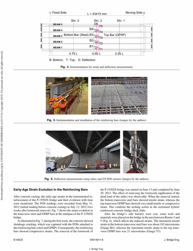
The P-15502S bridge (Fig. 1) was instrumented with Fabry-PerotFOSs at critical locations to record the reinforcement strains. In-strumentation was distributed along the midspan section of the
bridge, as shown in Fig. 4. The FOSs were glued to the transverseGFRP reinforcing bars in the top mat and the transverse steel bars inthe bottom mat. The FOSs were glued to the GFRP bars (T1–T5) atthe locations of support girders (maximum negative moment) andto the steel bars (B1–B4) at the centerlines between the supportgirders (maximum positive moment) (Fig. 4). The GFRP and steelbars were instrumented at the structural laboratory of the Universityof Sherbrooke. Thereafter, the bars were shipped to the constructionsite, where they were installed in the designated locations. Fig. 5shows both the instrumentation of the reinforcing bars and the in-stallation of the instrumented bars in the field. The objective of usingFOSs was to allow for the long-term monitoring and future fieldtesting of the bridge. The Fabry-Perot FOSs usedweremanufacturedby Roctest (Saint-Lambert, Quebec, Canada).
During static tests of the P-15502S bridge, the deflection of thesteel girders was measured (D1–D5) with a theodolite and a systemof rulers installed at the bridge midspan (Fig. 3). The deflection wasalsomeasuredwith two general-purpose digital-contact sensorswitha 50-mm range (GT2-H50) located at D2 and D4 (Beams 2 and 4;Fig. 2). Fig. 6 shows the ruler system and the two GT2-H50 sensorsduring bridge testing. The GT2-H50 sensors were manufactured byOsmos Canada (Montréal, Quebec, Canada).
Fig. 3. Bridge construction: (a) bottom reinforcing steel; (b) bottom and top reinforcement; (c) completed reinforcement of the bridge deck;(d) concrete casting (images by the authors)
Table 1. Properties of the Glass Fiber–Reinforced Polymer and Steel Reinforcing Bars
Reinforcing bar type Gradea Bar sizea Areaa (mm2)Elastic tensile
modulus Ef (GPa)Ultimate tensilestrength (MPa)
Characteristic tensilestrengthb (MPa)
Ultimate tensileelongation (%)
Glass fiber–reinforced polymer II Number 20 284 54:36 0:8 1,3936 8 1,369 2.56Steel — 15M 200 200 fy 5 400c — —
— 20M 300 200 fy 5 400c — —aAccording to CSA (2010).bCharacteristic tensile strength 5 average value – 33 standard deviation (CSA 2012).cThe quantity fy is the yield strength of steel bars.
© ASCE 04014011-5 J. Bridge Eng.
J. Bridge Eng.
Dow
nloa
ded
from
asc
elib
rary
.org
by
UN
IVE
RSI
TE
DE
SH
ER
BR
OO
KE
on
01/1
7/14
. Cop
yrig
ht A
SCE
. For
per
sona
l use
onl
y; a
ll ri
ghts
res
erve
d.
Early-Age Strain Evolution in the Reinforcing Bars
After concrete casting, the early-age strains in the instrumented re-inforcement of the P-15502S bridge and their evolution with timewere monitored. The FOS readings were recorded from May 31,2012 (initial reading before concrete casting) to July 12, 2012 (twoweeks after formwork removal). Fig. 7 shows the strain evolution inthe transverse steel and GFRP bars at the midspan of the P-15502Sbridge.
As illustrated inFig. 7, during the first week, the concrete showedshrinkage cracking, which was captured with the FOSs attached tothe reinforcing bars (steel andGFRP). Consequently, the reinforcingbars showed compressive strains. The removal of the formwork of
the P-15502S bridge was started on June 13 and completed by June29, 2012. The effect of removing the formwork (application of thedead load of the slabs) was observable. When the removal started,the bottom transverse steel bars showed tensile strain, whereas thetop transverse GFRP bars showed very small tensile or compressivestrain. This confirms the arching action in the restrained hybrid-reinforced-concrete bridge-deck slabs.
After the bridge’s side barriers were cast, some tools andmaterials were placed on the bridge in the area between Beams 3 and5 (Fig. 4), which affects the induced strains. The maximum tensilestrain in the bottom transverse steel bars was about 165 microstrains(Gauge B4), whereas the maximum tensile strain in the top trans-verse GFRP bars was 21 microstrains (Gauge T3).
Fig. 4. Instrumentation for strain and deflection measurements
Fig. 5. Instrumentation and installation of the reinforcing bars (images by the authors)
Fig. 6. Deflection measurements using rulers and GT-H50 sensors (images by the authors)
© ASCE 04014011-6 J. Bridge Eng.
J. Bridge Eng.
Dow
nloa
ded
from
asc
elib
rary
.org
by
UN
IVE
RSI
TE
DE
SH
ER
BR
OO
KE
on
01/1
7/14
. Cop
yrig
ht A
SCE
. For
per
sona
l use
onl
y; a
ll ri
ghts
res
erve
d.

Live-Load Testing of the P-15502S Bridge
The P-15502S bridge was tested on October 30, 2012, for serviceperformance, as specified by the CSA (2006) using three three-axlecalibrated trucks. Trucks 1–3 had loads of about 72 kN on the frontaxle and approximately 88 kN on each back axle. Fig. 8(a) illustratesthe trucks. The bridge deck was tested along six loading paths usingone, two, and three trucks at three different stations (truck stops) inthe bridge’s longitudinal direction (Stations 1–3). The stations wereselected at the quarter-points and midpoint of the bridge to capturevariations in the straining actions according to the truck locations onthe bridge. The six loading paths, shown in Fig. 8(b), were markedon the bridge deck aswere the three stations. Readingswere recordedat a truck station when the midpoint of the truck’s second and thirdaxles was directly over the station. Fig. 9 shows the trucks on thebridge during testing.
Live-Load Test Results
After each loading pass, the deck slab of the P-15502S bridge wasvisually checked for any signs of cracking over the girders(negative-moment areas). No cracks were observed at any locationin the top surface of the bridge deck at the girder locations.
Strain Measurements
Fig. 10 shows strain variation in the bottom transverse steel bars andthe top transverse GFRP bars according to truck location on thebridge. Themaximumstrainswere recordedwhen the trucks stoppedin themiddle of the bridge (Station 2). Fig. 11 presents themaximumstrains resulting from the different loading paths when the truckswere in themiddle of the bridge. Generally, the strainswere very lowin the bottom transverse steel bars and top transverseGFRPbars. Thestrain in the bottom transverse steel bars at its maximum locationwas 15 microstrains, and the strain in the top transverse GFRP bars
Fig. 7. Early-age strain evolution in the reinforcing bars under deadload: (a) top transverse GFRP bars; (b) bottom transverse steel bars
Fig. 8. Truck loads and loading paths in cross section during testing: (a) truck loads; (b) testing paths
© ASCE 04014011-7 J. Bridge Eng.
J. Bridge Eng.
Dow
nloa
ded
from
asc
elib
rary
.org
by
UN
IVE
RSI
TE
DE
SH
ER
BR
OO
KE
on
01/1
7/14
. Cop
yrig
ht A
SCE
. For
per
sona
l use
onl
y; a
ll ri
ghts
res
erve
d.

reached a maximum of 25 microstrains. It should be noted thatstrains in steel reinforcing bars of the same order as those measuredin this paper were reported for similar bridges that were constructedusing FRP or steel bars in their concrete deck slabs (El-Salakawyet al. 2003b, 2005; Benmokrane et al. 2006, 2007).
The maximum measured tensile strains in the GFRP barswere less than 1% of the GFRP’s ultimate strains (1,390=54,3005 25,600 microstrains). The design service load of 110.25 kN[specified by the CSA (2006)] is approximately 2.5 times greaterthan themaximumwheel load of 45 kN [Fig. 8(a)] for the trucks usedin the field test. If the maximum values of the strains measured inthe field are linearly extrapolated (multiplied by 2.5), however, theresulting values for the tensile strainswill be about 63microstrains inthe top transverse GFRP bars. These values are still less than 1%of the ultimate strains of the GFRP bars. According to the CSA(2006), the allowable stress or strain limit for GFRP bars in concreteslabs is 25% of the material’s ultimate stress or strain values. Similarextrapolation of the strains in the bottom transverse steel bars yieldeda strain value of about 2% of the ultimate strain capacity of the steelbars (based on a yield strain of 2,000 microstrains), which is alsovery low.
The very small measured strains (Fig. 11) indicate the presenceof arching action in the restrained hybrid-reinforced-concretebridge-deck slabs. Although the bridge deck was designed ac-cording to the CHBDC’s flexural design method (CSA 2006), theslabs did not show real flexural response attributable to the arch-action effect. Furthermore, because the bridge deck meets CHBDCrequirements (CSA 2006) for the empirical method, it was possibleto design it using the empirical method. The bridge deck’s designbased on the empirical method yields 15M steel bars at 300 mm asbottom transverse reinforcement (minimum reinforcement), 15Msteel bars at 300 mm (minimum reinforcement) as bottom longi-tudinal reinforcement, andNo. 15GFRPbars at 300mm (minimum
reinforcement) as top transverse and longitudinal reinforcement.This design saves a significant amount of transverse reinforcement(steel and GFRP bars) compared with the design using the flexuralmethod.
Deflection Measurements
Fig. 12(a) shows the variation of the measured deflection of the steelgirders with the truck location along the bridge, whereas Fig. 12(b)presents the deflection of the steel girders at the bridge midspanattributable to trucks located at the midspan (Station 2) for thedifferent paths. The measured deflection indicates that the truckloading was not evenly distributed on the steel girders. The girderclosest to the loading path deformed more than those further away.This wasmore obvious when the truck traveled over or near the edgegirder. As shown in Fig. 12(b), the single truck following Path 1[over Girder 5 on the edge; see Fig. 8(b)] produced the peak de-flection in Girder 5 of 12.0 mm (L=3,617). The peak deflection withthe two calibrated trucks traveling simultaneously along Paths 4 and5 was 14.0 mm (L=3,101) in Girder 2. Furthermore, as noted withPaths 4 and 5, the deflection distribution was better when the loadwas applied to two lanes, as evidenced by Fig. 12(b).
Fig. 13 shows the continuous deflectionmeasurements forBeams2 and 3 using the G2-H50 sensors during the field test. Comparingthe results presented in Figs. 12 and 13 reveals that the conventionalrulers and theodolite system yielded deflection measurements veryclose to that provided by the G2-H50 sensors. Considering Path 6and Station 2, the deflection of Beam2was 20.5mmaccording to therulers and theodolite system [Fig. 12(b)] and 19.51 mm according tothe G2-H50 sensors (Fig. 13). Thus, this systemmay be a viable toolwhen such advanced techniques are not available. Advanced opticalsensors, however, have the advantage of being able to capture thedynamic response when needed.
Fig. 9. Trucks during testing (images by the authors)
Fig. 10. Variation of strains according to truck location
© ASCE 04014011-8 J. Bridge Eng.
J. Bridge Eng.
Dow
nloa
ded
from
asc
elib
rary
.org
by
UN
IVE
RSI
TE
DE
SH
ER
BR
OO
KE
on
01/1
7/14
. Cop
yrig
ht A
SCE
. For
per
sona
l use
onl
y; a
ll ri
ghts
res
erve
d.

Live-Load Distribution Factors
Many techniques are available to determine transverse live-loaddistribution or girder distribution factors (DFs). Zokaie et al.(1991) grouped analytical techniques into three different levels of
analysis from detailed modeling to simplified equations. Fieldtesting can also provide information on live-load DFs for a givenbridge type and geometry (Kim and Nowak 1997; Barr et al. 2001;Eom and Nowak 2001; Schwarz and Laman 2001). The DFs can bedetermined from field measurements using
DFi ¼ di=P
di (1)
where di 5 maximum static deflection in the ith girder.The deflection measurements shown in Fig. 12 for the P-15502S
bridge were used to determine the live-load distribution factorsaccording to Eq. (1). From AASHTO (2012), live-load distributionfactors are provided that can be compared with the measured DFs.The exterior girder (Beam 5; Fig. 1) deflected 12 mm under loadingPath 1. The total deflection of all of the girders was 33mm for a live-load DF of about 12=32 or 0.38. The AASHTO (2012) live-loaddistribution factors are 0.65 using the lever rule and 0.46with specialanalysis. These factors are based on load and bridge geometry andexclude the 1.2 multiple presence factor (AASHTO 2012, Article4.6.2.2.2d). The interior girder (Beam 3; Fig. 1) deflected 7 mmunder loading Path 3 (Fig. 12). The total deflection of all of thegirderswas 28mm for a live-load distribution factor of about 7=28 or0.25. The AASHTO (2012) live-load distribution factor is 0.45. Thelive-load distribution factor depends on girder spacing, span length,and girder rigidity. Thus, it may be concluded that the DFs ofAASHTO (2012) tend to be more conservative than the measuredvalues.
Conclusions
This paper presents the construction details and the live-load fieldtesting of the hybrid-reinforced Sainte Catherine overpass locatedon Highway 410 (Sherbrooke, Quebec). Based on the details pre-sented in this paper and the results of the field-loading test, thefollowing conclusions can be drawn:• The maximum tensile strain in the top transverse GFRP bars was
less than 1% of the ultimate tensile strain of the GFRP bars.Nevertheless, it is lower than the strains expected with the flexuraldesign method. This result suggests that the CSA (2006) flexuraldesign method overestimates the calculated design moments.
• The very small measured strains in the GFRP reinforcing barsindicate the presence of arching action between the girders in the
Fig. 11. Reinforcement strains: (a) strains in GFRP bars; (b) strains insteel bars
Fig. 12.Maximummeasured deflection of steel girders (trucks at midspan; Station 2): (a) variation with the truck location; (b) deflection of all girders
© ASCE 04014011-9 J. Bridge Eng.
J. Bridge Eng.
Dow
nloa
ded
from
asc
elib
rary
.org
by
UN
IVE
RSI
TE
DE
SH
ER
BR
OO
KE
on
01/1
7/14
. Cop
yrig
ht A
SCE
. For
per
sona
l use
onl
y; a
ll ri
ghts
res
erve
d.

restrained hybrid-reinforced-concrete bridge decks. In the un-likely occurrence of field failure, the mode would be punchingshear.
• When hybrid-reinforced-concrete bridge decks meet the CHBDCrequirements (CSA2006) concerning the empirical designmethod,they could be designed accordingly, which could save significantamounts of transverse reinforcement.
• The conventional rulers and theodolite system may be a viablemethod to measure the deflection of bridge girders during fieldtesting when advanced systems are not available. This would notapply, however, if the dynamic response were of interest.
• The DFs of AASHTO (2012) tend to be more conservative thanthe measured values.
• The tests conducted in this paper confirmed that the behavior ofhybrid-reinforced-concrete bridge decks is similar to that totallyreinforced with FRP or steel bars. This hybrid concept may be aviable solution for concrete bridge decks with extended servicelife.
• The continuous monitoring of the bridge deck will enableunderstanding of the long-term structural behavior and perfor-mance in real environmental and service conditions. The resultsof such applications along with the compelling evidence pre-sented on the durability of GFRP reinforcement from bridges indifferent environments (Mufti et al. 2005, 2007; 2011) encour-age wider acceptance of this technology. They will also lead tocost-effective design of concrete structures/bridges with ex-tended service life.
Acknowledgments
This research received financial support from the Natural Scienceand Engineering Research Council of Canada (NSERC), the Fondsquébécois de la recherche sur la nature et les technologies (FQR-NT), and the Ministry of Transportation of Quebec (MTQ). Theauthors are also grateful to CIMA1 (Sherbrooke, Quebec, Canada),the S.M.Group International. (Sherbrooke,Quebec, Canada), Sintra(Sherbrooke, Quebec, Canada), and the technical staff of the struc-tural laboratory at the University of Sherbrooke, especially Martin
Bernard and Simon Kelly, for their assistance in instrumenting andtesting the bridge.
References
AASHTO. (2012). LRFD bridge design specifications, 6th Ed., Washington,DC.
Ahmed, E., and Benmokrane, B. (2012). “Hybrid reinforced concrete bridgedeck slab of 410 Overpass Bridge in Quebec: Construction and testing.”Proc., 3rd Int. Structural Specialty Conf., Canadian Society for CivilEngineering, Montreal.
Ahmed, E. A., and Benmokrane, B. (2011). “Static testing of full-scaleconcrete bridge barriers reinforced with GFRP bars.” Proc., 10th Int.Symp. on Fiber-Reinforced Polymer Reinforcement for Concrete Struc-tures (FRPRCS-10), R. Sen et al., eds., American Concrete Institute,Farmington Hills, MI, 5.1–5.20.
Ahmed, E. A., Dulude, C., and Benmokrane, B. (2013). “GFRP-reinforcedconcrete bridge barriers: Static tests and pendulum impacts.”Can. J. Civ.Eng., 40(11), 1050–1059.
Barr, P. J., Eberhard,M.O., andStanton, J. F. (2001). “Live-load distributionfactors in prestressed concrete girder bridges.” J. Bridge Eng., 10.1061/(ASCE)1084-0702(2001)6:5(298), 298–306.
Benmokrane, B., El-Salakawy, E., Desgagné, G., and Lackey, T. (2004).“FRP bars for bridges.” Concr. Int., 26(8), 84–90.
Benmokrane, B., El-Salakawy, E., El-Gamal, S., and Goulet, S. (2007).“Construction and testing of Canada’s first concrete bridge deck totallyreinforced with glass FRP bars: Val-Alain bridge on Highway 20East.” J. Bridge Eng., 10.1061/(ASCE)1084-0702(2007)12:5(632),632–645.
Benmokrane, B., El-Salakawy, E. F., El-Ragaby, A., and Lackey, T. (2006).“Designing and testing of concrete bridge decks reinforced with glassFRP bars.” J. Bridge Eng., 10.1061/(ASCE)1084-0702(2006)11:2(217),217–229.
Canadian Standards Association (CSA). (2006). “Canadian highway bridgedesign code.” CAN/CSA S6–06, Rexdale, ON, Canada.
Canadian Standards Association (CSA). (2010). “Specification for fibre-reinforced polymers.” CAN/CSA S807–10, Rexdale, ON, Canada.
Canadian Standards Association (CSA). (2012). “Design and constructionof building structures with fibre reinforced polymers.” CAN/CSA S806–12, Rexdale, ON, Canada.
Fig. 13. Measured deflection of steel girders using G2-H50 sensors
© ASCE 04014011-10 J. Bridge Eng.
J. Bridge Eng.
Dow
nloa
ded
from
asc
elib
rary
.org
by
UN
IVE
RSI
TE
DE
SH
ER
BR
OO
KE
on
01/1
7/14
. Cop
yrig
ht A
SCE
. For
per
sona
l use
onl
y; a
ll ri
ghts
res
erve
d.

Eamon, D. C., Jensen, E. A., Grace, N. F., and Shi, X. (2012). “Life-cyclecost analysis of alternative reinforcement materials for bridge super-structures considering cost and maintenance uncertainties.” J. Mater.Civ. Eng., 10.1061/(ASCE)MT.1943-5533.0000398, 373–380.
El-Gamal, S., El-Salakawy, E., and Benmokrane, B. (2005). “Behavior ofconcrete bridge deck slabs reinforced with fiber-reinforced polymer barsunder concentrated loads.” ACI Struct. J., 102(5), 727–735.
El-Gamal, S., El-Salakawy, E., and Benmokrane, B. (2007). “Influence ofreinforcement on the behavior of concrete bridge deck slabs reinforcedwith FRP bars.” J. Compos. Constr., 10.1061/(ASCE)1090-0268(2007)11:5(449), 449–458.
El-Ragaby, A., El-Salakawy, E., and Benmokrane, B. (2007a). “Fatigueanalysis of concrete bridge deck slabs reinforced with E-glass/vinyl esterFRP reinforcing bars.” Composites Part B, 38(5–6), 703–711.
El-Ragaby, A., El-Salakawy, E., and Benmokrane, B. (2007b). “Fatiguelife evaluation of concrete bridge deck slabs reinforced with glassFRP composite bars.” J. Compos. Constr., 10.1061/(ASCE)1090-0268(2007)11:3(258), 258–268.
El-Salakawy, E., Benmokrane, B.,Masmoudi, R., Brière, F., andBreaumier,E. (2003a). “Concrete bridge barriers reinforced with glass fiber-reinforced polymer composite bars.” ACI Struct. J., 100(6), 815–824.
El-Salakawy, E., Masmoudi, R., Benmokrane, B., Brière, F., and Desgagné,G. (2004). “Pendulum impacts into concrete bridge barriers reinforcedwith glass fibre reinforced polymer composite bars.” Can. J. Civ. Eng.,31(4), 539–552.
El-Salakawy, E. F., and Benmokrane, B. (2003). “Design and testing ofa highway concrete bridge deck reinforced with glass and carbon FRPbars.” Field applications of FRP reinforcement: Case studies, AmericanConcrete Institute, Detroit, 37–54.
El-Salakawy, E. F., Benmokrane, B., and Desgagné, G. (2003b). “FRPcomposite bars for the concrete deck slab ofWotton bridge.”Can. J. Civ.Eng., 30(5), 861–870.
El-Salakawy, E. F., El-Ragaby, A., and Nadeau, D. (2005). “Field in-vestigation on the first bridge deck slab reinforced with glass FRP
bars constructed in Canada.” J. Compos. Constr., 10.1061/(ASCE)1090-0268(2005)9:6(470), 470–479.
Eom, J., and Nowak, A. S. (2001). “Live load distribution for steel girderbridges.” J. Bridge Eng., 10.1061/(ASCE)1084-0702(2001)6:6(489),489–497.
Kim, S., and Nowak, A. S. (1997). “Load distribution and impact factors forI-girder bridges.” J. Bridge Eng., 10.1061/(ASCE)1084-0702(1997)2:3(97), 97–104.
Mufti, A., et al. (2005). “Durability of GFRP reinforced concrete in fieldstructures.” Proc., 7th Int. Symp. on Fiber-Reinforced Polymer (FRP)Reinforcement for Concrete Structures (FRPRCS), American ConcreteInstitute, Farmington Hills, MI, 1361–1378.
Mufti, A., Banthia, N., Benmokrane, B., Boulfiza, M., and Newhook, J.(2007). “Durability of GFRP composite rods.”Concr. Int., 29(2), 37–42.
Mufti, A. A., and Neale, K. W. (2007). “State-of-the-art of FRP and SHMapplications in bridge structures in Canada.” Proc., Composites &Polycon 2007, American Composites Manufacturers Association(ACMA), Arlington, VA.
Mufti, A. A., Newhook, J., Benmokrane, B., Tadros, G., and Vogel, H. M.(2011). “Durability of GFRP rods in field demonstration projects acrossCanada.” Proc., 4th Int. Conf. on Durability & Sustainability of FibreReinforced Polymer (FRP) Composites for Construction and Re-habilitation of Structures (CDCC2011), B. Benmokrane, E. El-Sala-kawy, and E. Ahmed, eds., Quebec City, 27–35.
Phillips, K. A., Harlan, M., Roberts-Wollmann, C. L., and Cousins, T. E.(2005). “Performance of a bridge deck with glass fiber reinforcedpolymer bars as the topmat of reinforcement.” Technical Rep. No. VTRC05-CR24, Federal Highway Administration, Washington, DC.
Schwarz, M., and Laman, L. A. (2001). “Response of prestressed concreteI-girder bridges to live load.” J. Bridge Eng., 10.1061/(ASCE)1084-0702(2001)6:1(1), 1–8.
Zokaie, T., Osterkamp, T. A., and Imbsen, R. A. (1991). “Distribution ofwheel loads on highway bridges.” Final Rep. NCHRP 12-26/1, NationalCooperative Highway Research Program, Washington, DC.
© ASCE 04014011-11 J. Bridge Eng.
J. Bridge Eng.
Dow
nloa
ded
from
asc
elib
rary
.org
by
UN
IVE
RSI
TE
DE
SH
ER
BR
OO
KE
on
01/1
7/14
. Cop
yrig
ht A
SCE
. For
per
sona
l use
onl
y; a
ll ri
ghts
res
erve
d.


