Bond behaviour of GFRP reinforced geopolymer cement concrete
10
Bond behaviour of GFRP reinforced geopolymer cement concrete Biruk Hailu Tekle 1 , Amar Khennane 1* , Obada Kayali 1 1 SEIT, UNSW Canberra, Northcott Drive, Canberra ACT 2600, Australia Abstract. Bond plays a key role in the performance of reinforced concrete structures. Glass fibre reinforced polymer (GFRP) reinforcing bar and Geopolymer cement (GPC) concrete are promising alternative construction materials for steel bars and Ordinary Portland Cement (OPC) concrete respectively. In this study, the bond behaviour between these two materials is investigated by using beam-end specimen tests. The bond behaviour of 15.9 mm diameter sand-coated GFRP bar was investigated. An embedment length of six and nine times the bar diameter were used. The free end and the loaded end bond-slip-relationships, the bond failure mode and the average bond stress were used to analyse each of the specimens. Additionally, the distribution of tensile and bond stress along the embedment length was investigated by installing strain gauges along the embedment length in some of the specimens. Test results indicate that a significant difference exists between the free end and loaded end bond-slip curves, which is due to the lower elastic modulus of the GFRP bars. Furthermore, it was found that the tensile and bond stress distribution along the embedment length is nonlinear and the nonlinearity changes with the load. 1 Introduction Corrosion of reinforcing steel bars and environmental problems associated with Ordinary Portland cement (OPC) concrete have lead researchers to look for new construction materials. These materials ideally are to be noncorrosive and environmentally friendly while providing the required mechanical performances. Glass fiber reinforced polymer (GFRP) reinforced Geopolymer cement (GPC) concrete stand out to be good alternatives with these desired properties. GFRP bars are characterized by high tensile strength, high durability, light weight, and electromagnetic permeability [1], while GPC concrete exhibits rapid a rate of strength development, resistance to sulphate attack, acid resistance, little drying shrinkage, low creep, improved resistance to fire, and prolonged handling time [2, 3, 4]. For GFRP bar and Geopolymer concrete to be used together, they should show a good composite action. The composite action is developed through the bond between the concrete and the surface of the bar. In reinforced concrete structures, bond achieves the transfer of load from the concrete to the reinforcing bar. In such a way, the weak tensile strength of concrete is assisted by the high tensile strength of the bar. There are many studies carried out * Corresponding author: [email protected] DOI: 10.1051/ , 04002 (2017) 71200 1 MATEC Web of Conferences 20 matecconf/201 ASCMCES-17 4002 © The Authors, published by EDP Sciences. This is an open access article distributed under the terms of the Creative Commons Attribution License 4.0 (http://creativecommons.org/licenses/by/4.0/).
Transcript of Bond behaviour of GFRP reinforced geopolymer cement concrete

Bond behaviour of GFRP reinforced geopolymer cement concrete
Biruk Hailu Tekle1, Amar Khennane1*, Obada Kayali1 1SEIT, UNSW Canberra, Northcott Drive, Canberra ACT 2600, Australia
Abstract. Bond plays a key role in the performance of reinforced concrete structures. Glass fibre reinforced polymer (GFRP) reinforcing bar and Geopolymer cement (GPC) concrete are promising alternative construction materials for steel bars and Ordinary Portland Cement (OPC) concrete respectively. In this study, the bond behaviour between these two materials is investigated by using beam-end specimen tests. The bond behaviour of 15.9 mm diameter sand-coated GFRP bar was investigated. An embedment length of six and nine times the bar diameter were used. The free end and the loaded end bond-slip-relationships, the bond failure mode and the average bond stress were used to analyse each of the specimens. Additionally, the distribution of tensile and bond stress along the embedment length was investigated by installing strain gauges along the embedment length in some of the specimens. Test results indicate that a significant difference exists between the free end and loaded end bond-slip curves, which is due to the lower elastic modulus of the GFRP bars. Furthermore, it was found that the tensile and bond stress distribution along the embedment length is nonlinear and the nonlinearity changes with the load.
1 Introduction Corrosion of reinforcing steel bars and environmental problems associated with Ordinary Portland cement (OPC) concrete have lead researchers to look for new construction materials. These materials ideally are to be noncorrosive and environmentally friendly while providing the required mechanical performances. Glass fiber reinforced polymer (GFRP) reinforced Geopolymer cement (GPC) concrete stand out to be good alternatives with these desired properties. GFRP bars are characterized by high tensile strength, high durability, light weight, and electromagnetic permeability [1], while GPC concrete exhibits rapid a rate of strength development, resistance to sulphate attack, acid resistance, little drying shrinkage, low creep, improved resistance to fire, and prolonged handling time [2, 3, 4].
For GFRP bar and Geopolymer concrete to be used together, they should show a good composite action. The composite action is developed through the bond between the concrete and the surface of the bar. In reinforced concrete structures, bond achieves the transfer of load from the concrete to the reinforcing bar. In such a way, the weak tensile strength of concrete is assisted by the high tensile strength of the bar. There are many studies carried out
* Corresponding author: [email protected]
DOI: 10.1051/, 04002 (2017) 712001MATEC Web of Conferences 20 matecconf/201ASCMCES-17
4002
© The Authors, published by EDP Sciences. This is an open access article distributed under the terms of the CreativeCommons Attribution License 4.0 (http://creativecommons.org/licenses/by/4.0/).
on the bond properties of GFRP bars with the normal OPC as well as with GPC concretes [5-9, 10-11]. However, with the exception of some recent works [12, 13], not much has been done on the bond properties of GFRP reinforced GPC concrete. Both Tekle et al [12] and Maranan et al [13] studies used pullout tests to compare the bond performace of GFRP reinoforced GPC concrete with GFRP reinforced OPC concrete and steel reinforced GPC concrete, respectively. These studies revealed the promising performance of the GFRP reinforced GPC concrete. Nonetheless, further research is still needed for a better understanding of the bond mechanisms between these two materials. The tensile and bond stress distributions along the embedment length of GFRP reinforced GPC concrete are two areas, which have not been studied yet. A nonlinear tensile stress and bond stress distribution have been reported for both GFRP and steel with OPC concrete [6]. As there are inherent differences in the surface deformations and mechanical conditions of GFRP bars from steel bars, design guidelines such as ACI 318-08 and ACI 408-03 developed for steel cannot be directly used for GFRP bars [14, 15]. The difference in the properties of GPC and OPC concrete may also affect the bond properties, which again makes it inconvenient to use models and guidelines developed for GFRP reinforced OPC concrete such as ACI 440.1R-03 [16]. Thus, the aim of this study is to provide more understanding of the bond between GFRP and GPC concrete using a more reliable test method (beam-end specimen) according to ASTM A944 [17].
2 Experimental program
2.1 Materials
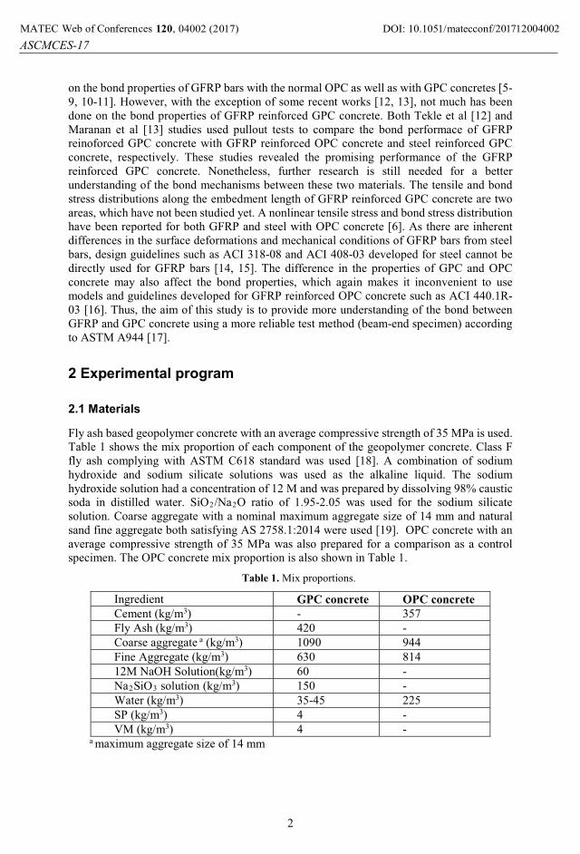
Fly ash based geopolymer concrete with an average compressive strength of 35 MPa is used. Table 1 shows the mix proportion of each component of the geopolymer concrete. Class F fly ash complying with ASTM C618 standard was used [18]. A combination of sodium hydroxide and sodium silicate solutions was used as the alkaline liquid. The sodium hydroxide solution had a concentration of 12 M and was prepared by dissolving 98% caustic soda in distilled water. SiO2/Na2O ratio of 1.95-2.05 was used for the sodium silicate solution. Coarse aggregate with a nominal maximum aggregate size of 14 mm and natural sand fine aggregate both satisfying AS 2758.1:2014 were used [19]. OPC concrete with an average compressive strength of 35 MPa was also prepared for a comparison as a control specimen. The OPC concrete mix proportion is also shown in Table 1.
Table 1. Mix proportions.
Ingredient GPC concrete OPC concrete
Cement (kg/m3) - 357Fly Ash (kg/m3) 420 -Coarse aggregate a (kg/m3) 1090 944Fine Aggregate (kg/m3) 630 81412M NaOH Solution(kg/m3) 60 -Na2SiO3 solution (kg/m3) 150 -Water (kg/m3) 35-45 225SP (kg/m3) 4 -VM (kg/m3) 4 -
a maximum aggregate size of 14 mm
DOI: 10.1051/, 04002 (2017) 712001MATEC Web of Conferences 20 matecconf/201ASCMCES-17
4002
2
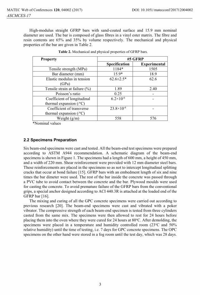
High-modulus straight GFRP bars with sand-coated surface and 15.9 mm nominal diameter are used. The bar is composed of glass fibres in a vinyl ester matrix. The fibre and resin contents are 65% and 35% by volume respectively. The mechanical and physical properties of the bar are given in Table 2.
Table 2. Mechanical and physical properties of GFRP bars.
Property #5 GFRP
Specification Experimental
Tensile strength (MPa) 1184* 1505Bar diameter (mm) 15.9* 18.9
Elastic modulus in tension (GPa)
62.6±2.5* 62.6
Tensile strain at failure (%) 1.89 2.40Poisson’s ratio 0.25 -
Coefficient of longitudinal thermal expansion (/oC)
6.2×10⁻⁶ -
Coefficient of transverse thermal expansion (/oC)
23.8×10⁻⁶ -
Weight (g/m) 558 576*Nominal values
2.2 Specimens Preparation
Six beam-end specimens were cast and tested. All the beam-end test specimens were prepared according to ASTM A944 recommendation. A schematic diagram of the beam-end specimens is shown in Figure 1. The specimens had a length of 600 mm, a height of 450 mm, and a width of 220 mm. Shear reinforcement were provided with 12 mm diameter steel bars. These reinforcements are placed in the specimens so as not to intercept longitudinal splitting cracks that occur at bond failure [15]. GFRP bars with an embedment length of six and nine times the bar dimeter were used. The rest of the bar inside the concrete was passed through a PVC tube to avoid contact between the concrete and the bar. Plywood moulds were used for casting the concrete. To avoid premature failure of the GFRP bars from the conventional grips, a special anchor designed according to ACI 440.3R is attached at the loaded end of the GFRP bar [16].
The mixing and curing of all the GPC concrete specimens were carried out according to previous research [20]. The beam-end specimens were cast and vibrated with a poker vibrator. The compressive strength of each beam-end specimen is tested from three cylinders casted from the same mix. The specimens were then allowed to rest for 24 hours beforeplacing them into the oven where they were cured for 24 hours at 80oC. After demolding, the specimens were placed in a temperature and humidity controlled room (23oC and 50% relative humidity) until the time of testing, i.e. 7 days for GPC concrete specimens. The OPC specimens on the other hand were stored in a fog room until the test day, which was 28 days.
DOI: 10.1051/, 04002 (2017) 712001MATEC Web of Conferences 20 matecconf/201ASCMCES-17
4002
3
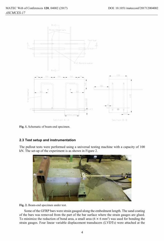
Fig. 1. Schematic of beam-end specimen.
2.3 Test setup and instrumentation
The pullout tests were performed using a universal testing machine with a capacity of 100 kN. The set-up of the experiment is as shown in Figure 2.
Fig. 2. Beam-end specimen under test.
Some of the GFRP bars were strain gauged along the embedment length. The sand coating of the bars was removed from the part of the bar surface where the strain gauges are glued. To minimize the reduction of bond area, a small area (6 × 6 mm2) was used for bonding the strain gauges. Four linear variable displacement transducers (LVDTs) were attached at the
DOI: 10.1051/, 04002 (2017) 712001MATEC Web of Conferences 20 matecconf/201ASCMCES-17
4002
4

free and loaded ends of the GFRP bar (two at each ends). The load was applied in displacement control mode at a rate of 1 mm/min. The strain, displacement and forces were recorded using an automatic data acquisition system.
3 Results and discussions
3.1 Failure mode and bond strength
The experimental results are given in Table 3. The specimens are identified by the type of concrete used (G for GPC concrete and O for OPC concrete), the diameter of the bar used, the embedment length as a multiple of the bar diameter (6d and 9d) and specimen number. The maximum pull out load was used to calculate the average bond stress by assuming a uniform bond stress distribution along the embedment length as per Eq. (1). The corresponding slips at this load are also reported for both free and loaded end:
� = �
��� (1)
where, � is average bond strength in MPa; P is applied pull out load in N; � is diameter of the rebar in mm; and � is bonded/embedded length in mm.
Table 3. Summary of experimental results.
Specimen Load
P max
(kN)
Average bond
stress
(MPa)
Free end
slip
(mm)
loaded end
slip (mm)
Failure
mode
G16-6d-1 67.9 14.2 265 498 SG16-6d-2 75.8 15.8 355 603 SG16-9d-1 81.3 11.3 580 824 TG16-9d-2 82.1 11.4 474 765 TG16-9d-3 88.6 12.2 448 562 TO16-9d-1 78.0 10.8 252 750 T
S = splitting failure; T = splitting of the concrete in the transverse direction
As shown in Figure 3, transverse tensile cracking caused the failure of the 9d specimens. The applied tensile load on the bar is transferred to the concrete via the bond. The concrete around the bonded region applies tensile stress on the concrete on the other side of the bonded region. This results in the tensile cracking at the end of the embedment length. Tekle et al. [12] reported the splitting failure of specimens with a similar embedment length in case of pullout cylinder specimens. In both the beam-end specimens of the present study and pullout specimens reported in [12], the tensile failure of the concrete causes a premature failure before the bond reaches its maximum strength. Nonetheless, the types of concrete failure observed in the pullout specimens [12], and the present beam-end specimens are different. This can be explained by considering the differences in the test specimens and their setup. The concrete in the pullout specimens are under compression due to the support condition. Furthermore, compressive struts are formed between support points for the concrete and the surface of the reinforcing bar placing the reinforcement surface in compression [15]. Unlike the pullout specimens, the beam-end specimens are in tension around the bonded region,hence more prone to tensile failure by cracking of the concrete in the transverse direction than in the pullout specimens.
DOI: 10.1051/, 04002 (2017) 712001MATEC Web of Conferences 20 matecconf/201ASCMCES-17
4002
5
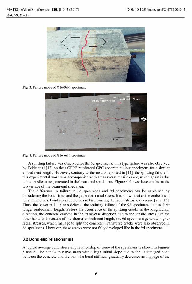
Fig. 3. Failure mode of O16-9d-1 specimen.
Fig. 4. Failure mode of G16-6d-1 specimen
A splitting failure was observed for the 6d specimens. This type failure was also observed by Tekle et al [12] on their GFRP reinforced GPC concrete pullout specimens for a similar embedment length. However, contrary to the results reported in [12], the splitting failure in this experimental work was accompanied with a transverse tensile crack, which again is due to the tensile stress generated in the beam-end specimens. Figure 4 shows these cracks on the top surface of the beam-end specimen.
The difference in failure in 6d specimens and 9d specimens can be explained by considering the bond stress and the generated radial stress. It is known that as the embedment length increases, bond stress decreases in turn causing the radial stress to decrease [7, 8, 12]. Thus, the lower radial stress delayed the splitting failure of the 9d specimens due to their longer embedment length. Before the occurrence of the splitting cracks in the longitudinal direction, the concrete cracked in the transverse direction due to the tensile stress. On the other hand, and because of the shorter embedment length, the 6d specimens generate higher radial stresses, which manage to split the concrete. Transverse cracks were also observed in 6d specimens. However, these cracks were not fully developed like in the 9d specimens.
3.2 Bond-slip relationships
A typical average bond stress-slip relationship of some of the specimens is shown in Figures 5 and 6. The bond-slip curve starts with a high initial slope due to the undamaged bond between the concrete and the bar. The bond stiffness gradually decreases as slippage of the
DOI: 10.1051/, 04002 (2017) 712001MATEC Web of Conferences 20 matecconf/201ASCMCES-17
4002
6
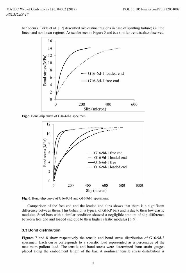
bar occurs. Tekle et al. [12] described two distinct regions in case of splitting failure; i.e.: the linear and nonlinear regions. As can be seen in Figure 5 and 6, a similar trend is also observed.
Fig.5. Bond-slip curve of G16-6d-1 specimen.
Fig. 6. Bond-slip curve of G16-9d-1 and O16-9d-1 specimens.
Comparison of the free end and the loaded end slips shows that there is a significant difference between them. This behavior is typical of GFRP bars and is due to their low elastic modulus. Steel bars with a similar condition showed a negligible amount of slip difference between free end and loaded end due to their higher elastic modulus [5, 9].
3.3 Bond distribution
Figures 7 and 8 show respectively the tensile and bond stress distribution of G16-9d-3specimen. Each curve corresponds to a specific load represented as a percentage of the maximum pullout load. The tensile and bond stress were determined from strain gauges placed along the embedment length of the bar. A nonlinear tensile stress distribution is
DOI: 10.1051/, 04002 (2017) 712001MATEC Web of Conferences 20 matecconf/201ASCMCES-17
4002
7
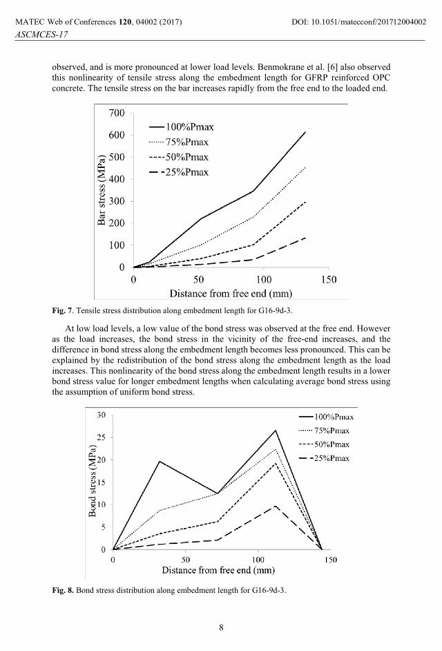
observed, and is more pronounced at lower load levels. Benmokrane et al. [6] also observed this nonlinearity of tensile stress along the embedment length for GFRP reinforced OPC concrete. The tensile stress on the bar increases rapidly from the free end to the loaded end.
Fig. 7. Tensile stress distribution along embedment length for G16-9d-3.
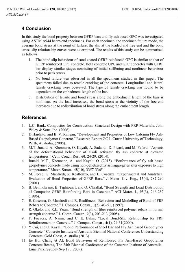
At low load levels, a low value of the bond stress was observed at the free end. However as the load increases, the bond stress in the vicinity of the free-end increases, and the difference in bond stress along the embedment length becomes less pronounced. This can be explained by the redistribution of the bond stress along the embedment length as the load increases. This nonlinearity of the bond stress along the embedment length results in a lower bond stress value for longer embedment lengths when calculating average bond stress using the assumption of uniform bond stress.
Fig. 8. Bond stress distribution along embedment length for G16-9d-3.
DOI: 10.1051/, 04002 (2017) 712001MATEC Web of Conferences 20 matecconf/201ASCMCES-17
4002
8
4 Conclusion In this study the bond property between GFRP bars and fly ash based GPC was investigated using ASTM A944 beam-end specimens. For each specimen, the specimen failure mode, the average bond stress at the point of failure, the slip at the loaded and free end and the bond stress-slip relationship curves were determined. The results of this study can be summarised as follows:
1. The bond slip behaviour of sand coated GFRP reinforced GPC is similar to that of GFRP reinforced OPC concrete. Both concrete OPC and GPC concretes with GFRP bar display similar stages consisting of initial stiffening and nonlinear behaviour prior to peak stress.
2. No bond failure was observed in all the specimens studied in this paper. The specimens failed due to tensile cracking of the concrete. Longitudinal and lateral tensile cracking were observed. The type of tensile cracking was found to be dependent on the embedment length of the bar.
3. Distribution of tensile and bond stress along the embedment length of the bars is nonlinear. As the load increases, the bond stress at the vicinity of the free-end increases due to redistribution of bond stress along the embedment length.
References1. L.C. Bank, Composites for Construction: Structural Design with FRP Materials. John
Wiley & Sons, Inc. (2006).2. D.Hardjito, and B. V. Rangan, “Development and Properties of Low Calcium Fly Ash-
Based Geopolymer Concrete.” Research Report GC 1, Curtin University of Technology, Perth, Australia, (2005).
3. M.T. Junaid, A. Khennane, O. Kayali, A. Sadaoui, D. Picard, and M. Fafard, “Aspects of the deformational behaviour of alkali activated fly ash concrete at elevated temperatures.” Cem. Concr. Res., 60, 24-29. (2014).
4. Junaid, M.T., Khennane, A., and Kayali, O. (2015). “Performance of fly ash based geopolymer concrete made using non-pelletized fly ash aggregates after exposure to high temperature.” Mater. Struct. 48(10), 3357-3365
5. M. Pecce, G. Manfredi, R. Realfonzo, and E. Cosenza, “Experimental and Analytical Evaluation of Bond Properties of GFRP Bars.” J. Mater. Civ. Eng., 13(4), 282-290 (2001).
6. B. Benmokrane, B. Tighiouart, and O. Chaallal, “Bond Strength and Load Distribution of Composite GFRP Reinforcing Bars in Concrete.” ACI Mater. J., 93(3), 246-252 (1996).
7. E. Cosezna, G. Manfredi and R. Realfonzo, “Behaviour and Modelling of Bond of FRP Rebars to Concrete.” J. Compos. Constr., 1(2), 40–51, (1997).
8. R. Okelo, and R.L. Yuan, “Bond strength of fiber reinforced polymer rebars in normal strength concrete.” J. Comp. Constr., 9(3), 203-213 (2005).
9. F. Focacci, A. Nanni, and C. E. Bakis, “Local Bond-Slip Relationship for FRP Reinforcement in Concrete.” J. Compos. Constr., 4(1), 24-31(2000).
10. Y.Cui, and O. Kayali, “Bond Performance of Steel Bar and Fly Ash based Geopolymer Concrete.” Concrete Institute of Australia Biennial National Conference: Understanding Concrete, Gold Coast, Australia (2013).
11. Ee Hui Chang et Al, Bond Behaviour of Reinforced Fly Ash-Based Geopolymer Concrete Beams, The 24th Biennial Conference of the Concrete Institute of Australia,. Luna Park, Sydney Sep 17, (2009).
DOI: 10.1051/, 04002 (2017) 712001MATEC Web of Conferences 20 matecconf/201ASCMCES-17
4002
9

12. B. H. Tekle, A. Khennane, O. Kayali “Bond properties of sand-coated GFRP bars with fly ash based geopolymer concrete.” J. Compos. constr. 20(5), (2016).
13. G., M. A. Maranan, “Bond Stress-Slip Behavior: Case of GFRP Bars in Geopolymer Concrete.” ASCE J. Mater. Civ. Eng., 27(1), 1-9. (2015).
14. American Concrete Institute (ACI). “Building Code Requirements for Structural Concrete and Commentary.” ACI 318M-08, Farmington Hills, Mich.
15. American Concrete Institute (ACI). “Bond and Development of Straight Reinforcing Bars in Tension.” ACI 408R-03, Farmington Hills, Mich.
16. ACI (American Concrete Institute). “Guide for the design and construction of structural concrete reinforced with FRP bars.” ACI 440.1R-06, Farmington Hills, MI. (2006).
17. American Society for Testing and Materials (ASTM). “Standard test method for comparing bond strength of steel reinforcing bars to concrete using beam-end specimens” ASTM A944 - 10, West Conshohocken, PA. (2010).
18. American Society for Testing and Materials (ASTM). “Standard Specification for Coal fly ash and raw or calcined natural pozzolan for use in concrete.” ASTM C618 - 12a, West Conshohocken, PA. (2012).
19. Australian Standard (AS). “Aggregates and rock for engineering purposes - Concrete aggregates.” AS 2758.1:2014. Australia. (2014).
20. M.T. Junaid, O. Kayali, A. Khennane and J. Black, “A mix design procedure for low calcium alkali activated fly ash-based concretes.” Constr. Build. Mater., 79, 301-310, (2015).
DOI: 10.1051/, 04002 (2017) 712001MATEC Web of Conferences 20 matecconf/201ASCMCES-17
4002
10