Conductive Concrete Overlay for Bridge Deck Deicing
57
Conducti veConcreteO verlayfo r Bridge Deck Deicing Sh er ifYehia,Ph.D.,PE March200 8
Transcript of Conductive Concrete Overlay for Bridge Deck Deicing

Conductive Concrete Overlay for
Bridge Deck Deicing
Sherif Yehia, Ph.D., PE
March 2008

Acknowledgment
ÅResearch TeamïChristopher Tuan, Ph.D., PEUniversity of Nebraska - Lincoln
ïOsama Abudayyeh, Ph.D., PE
ïIkhlas Abdel-Qader, Ph.D., PEWestern Michigan University
ïAmmar Zalt, Bridge Engineer, PARSONS
ïVijay Meganathan, Terasoft International Inc., Arlington Heights, IL
Outline
ÅBackground
ÅWhat is Conductive Concrete
ÅConductive Concrete Mix Design
ïMixing Procedure
ï Implementation Projects
ÅConstruction
ÅOperation
ÅModified Mix at Western Michigan University
ÅConcluding Remarks
ÅQuestions

Background
Existing Deicing Methods
ÅDeicing Chemicals
ÅInsulation against Freezing

Background
Heating Systems
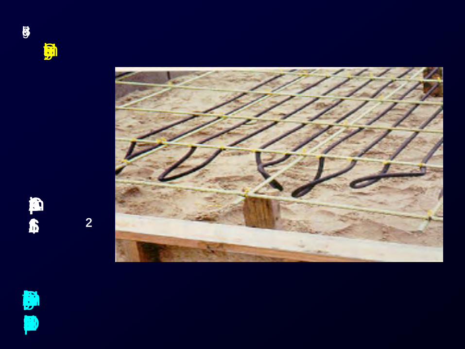
Electric Cables in the Bridge Approach
Roadway, Newark, New Jersey 1961
Approximate Cost
$5/ft2
Background
Heating Systems
Deck Heating System on Approaches of a
Pedestrian Overpass in Lincoln, NE, 1993
Approximate Cost
$16/ft2

Background
Heating Systems
Deck Heating System in the Buffalo
River Bridge, Amherst, Virginia, 1996
Approximate Cost
$35/ft2

ÅWhat is Conductive
Concrete?
ÅConductive Concrete
Applications
Conductive Concrete

Conductive Concrete Mix Design
The Conductive Concrete Mix Contains :
ïCarbon & Graphite Products
ïSteel Fiber
In addition to cement, fly ash, silica fume,
sand, coarse aggregate, water, and
superplasticizer

Deicing 1998
Deicing 1999

Deicing 2000

Mixing Procedure
(Mass production)

Mixing procedure
(Mass Production)

Mixing procedure
(Mass production)

Implementation Projects
ÅTest section on I-480 Missouri River
Bridge, 1999
ÅImplementation Project at Shelby City,
OH, 2001
ÅRoca Spur Bridge, Roca Nebraska, 2002

Test section on I-480 Missouri River
Bridge using conductive concrete
mix.
Implementation Project
Material evaluation - Durability test (I-480 Patch)
under traffic load and freeze-and-thaw action.
Poured on December 3, 1999


Implementation Project
at
Shelby City, OH
September 2001

Temperature Sensors

Site Before Casting Concrete
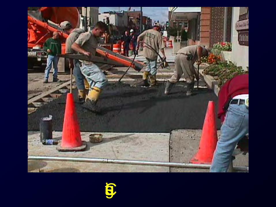
Casting

Finishing I

Finishing II

Finishing - Final Touch

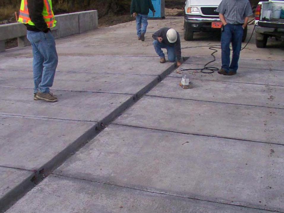
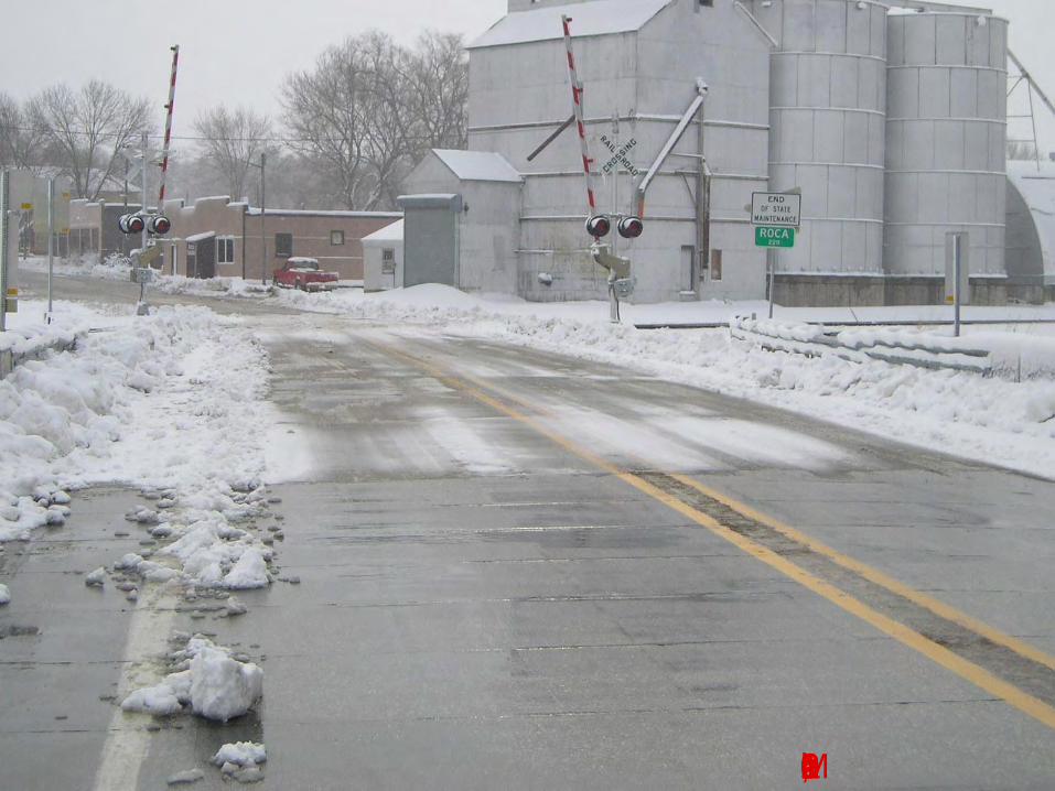
Implementation Project - Roca
Spur Bridge
ÅRoca, located about 15 miles south of Lincoln, Nebraska
ÅThe Roca Spur Bridge is a three-span slab type bridge has a 45.70m (150 ft) long and 11m (36 ft) wide concrete deck
ÅThe Bridge has a 36 m (117 ft) long and 8.5 m (28 ft) wide conductive concrete inlay
ÅThe inlay consists of 52 individual 1.2m 4.1m (4 ft 14 ft) conductive concrete slabs


Working with Ready Mix Concrete ïLincoln, NE
Mixing Procedure
ÅThe conductive concrete mix with steel fibers
and carbon and graphite products was used
to cast the inlay
ÅSeveral, two cubic yards, trial batches were
prepared to examine the mixing procedure
and travel time from the mixing plant to the
job site
ÅThe contractor and the pouring and finishing
crews practiced at a test site


March 21, 2006

Feb 13, 2007

Temperature Time History - Dec. 17, 2003
0.0
5.0
10.0
15.0
20.0
25.0
30.0
35.0
40.0
45.0
50.0
0.00 2.00 4.00 6.00 8.00 10.00 12.00 14.00
Time (hrs)
Te
mp
. (F
)Slab 1 Slab 2
Slab 3 Slab 4
Slab 5 Slab 6
Slab 7 Slab 8
Slab 9 Slab 10
Slab 11 Slab 12
Slab 13 Slab 14
Slab 15 Slab 16
Slab 17 Slab 18
Slab 19 Slab 20
Slab 21 Slab 22
Slab 23 Slab 24
Slab 25 Slab 26
Slab 27 Slab 28
Slab 29 Slab 32
Slab 33 Slab 34
Slab 35 Slab 36
Slab 37 Slab 38
Slab 39 Slab 40
Slab 41 Slab 42
Slab 43 Slab 44
Slab 45 Slab 46
Slab 47 Slab 48
Slab 49 Slab 50
Slab 51 Slab 52
Ambient

1
2
3
4
5
6
7
-25 -15 -5 5 15 25
Temperature (oC)
Ele
ctr
ica
l c
urr
en
t (A
mp
s.)
1/25/2004
2/1/2004
2/5/2004
1/6/2005
2/8/2005
2/17/2006
3/18/2006
1/13/2007
1/19/2007
2/13/2007
Stability of Electrical Conductivity

Modified Conductive Concrete
Mix Developed at WMU
ÅThe main objective of this research project
is to make the conductive concrete an
economical viable deicing method. This
can be achieved by the following:
ïReduction of the operating voltage and
current requirements.
ïDevelopment of a simplified mix procedure

Conductive Concrete Mix
Developed at WMU
ÅOptimization and mix proportioning
ÅEvaluation of the mechanical properties
of the optimized mix
ÅInvestigation of an electric model for the
optimized mix

Temp Vs Time
0
10
20
30
40
50
60
70
80
0 5 10 15 20 25 30 35 40 45
Time in Min
Te
mp
in F
Slab 1
Slab 2
Slab 3
Slab 4
Slab 5
Slab 6
Salb 7
Comparison of all Slabs Temperature readings

Temp vs Time
0
10
20
30
40
50
60
0 5 10 15 20 25 30 35 40 45
Time in Minutes
Tem
p in
F
Slab #4(80 volts)
Slab #5(80 Volts)
Slab #6 (80 volts)
Slab #4(60 volts)
Slab # 5(60 volts)
Slab #5 (100 volts)
Slab #6(100 volts)
Slab #4( 100 volts)
Temperature vs. Time Using Different
Voltage Values

Concluding Remarks
ÅThe conductive concrete deicing technology can
be readily implemented at accident-prone areas
such as bridge overpasses, exit ramps, airport
runways, street intersections, sidewalks, and
driveways
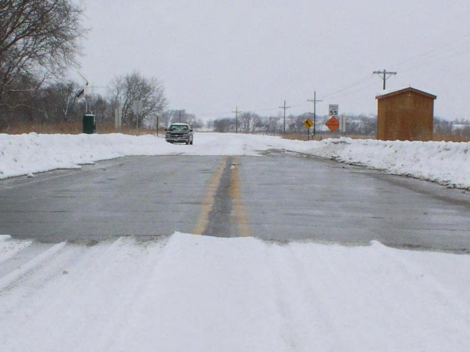
ÅThe heated bridge deck of Roca Spur Bridge is
the first implementation in the world of using
conductive concrete for highway bridge deicing

Concluding Remarks
ÅThe initial results showed that the modified
conductive concrete mix which was
developed at Western Michigan University
has the potential to be used for bridge
deck deicing application as well as the
proposed new applications including
Electromagnetic Shielding and Cathodic
protection of reinforcement.

Questions