CONDENSING SYSTEM INNOVATION AUTOMATIC MODULATING BOILER · CONDENSING SYSTEM INNOVATION AUTOMATIC...
56
Transcript of CONDENSING SYSTEM INNOVATION AUTOMATIC MODULATING BOILER · CONDENSING SYSTEM INNOVATION AUTOMATIC...


3
CONDENSING SYSTEM INNOVATION AUTOMATIC MODULATING BOILER
FOR CENTRAL HEATING AND DOMESTIC HOT WATER This new super high efficient turbo-modulating boiler is designed to meet domestic hot water and central heating requirements at super high efficiency, unheard of only a few years ago.POSITIONThe appliance is extremely versatile as it can be fitted in almost any room. The appliance is room sealed, there is no contact between combustion chamber and living accommodation. This guarantees maximum safety and efficiency. Indeed, our depression/combustion front cover has been designed to fit, achieving maximum air tight seal using screw down fasteners at 15 cm. This should not hinder service of the appliance, but does ensure maximum efficiency and safety - something which Ravenheat take great pride in.Each boiler has been designed and manufactured in our modern plant to exacting ISO 9001 discipline, all boilers carry full CE marking of approval. Technical sales and commercial service are available throughout the UK. This product is guaranteed by Ravenheat Manufacturing, Chartists Way, Morley, LEEDS, LS27 9ET. Telephone No (0113) 252 7007.BASIC COMPONENTS - (See figure 1)Guarantee is a full 12 months from date of purchase providing the appliance has been fitted in accordance with these instructions and relevant codes of practice.
- Gas valve with flame modulator.- Variable head pump suitable for any type of central heating system.- Burner with flame stabiliser designed to operate under all thermal conditions.- Primary heat exchanger constructed from copper.- Unique patented condensing heat exchanger for high thermal flue transfer gases to water.- Stainless steel plate heat exchanger for super high heat transfer to domestic hot water.- Highly reliable diverter valve with ethylene propylene diaphragm permitting primary flow circulation in the boiler during domestic hot water supply.- Built in frost protection. - Printed circuit board designed to connect to room stat and/or timer/frost stat. Aesthetically pleasing panels and controls.- On/Off ball valves for shutting off gas central heating and domestic hot water circuit Safety relief valve (for safety discharge).Programmable 7 day module with digital display (optional model).All front panel controls not often used have been hidden. This achieves simplicity of operation with easy to clean panels.
NOTE: Due to the high efficiency of this boiler a plume of water vapour will form at the flue terminal during operation.
COSHH - CONTROL OF SUBSTANCES HARMFUL TO HEALTHIMPORTANT
This appliance contains materials that are indicated below.It is the Users/Installers responsibility to ensure that the necessary personal protective clothing is-worn when han-dling, where applicable, the pertinent parts that contain any materials that cót3ld be interpreted as being injurious to health and safety.
WARNING When installing the appliance, care should be taken to avoid any possibility of injury when handling sheet metal parts.
GENERAL INFORMATION:GLUES AND SEALANTS - exercise caution - if these are still in liquid form.INSULATION PADS, CERAMIC FIBRE - may be harmful if inhaled, may be irritating to skin, eyes, nose and throat.When handling keep dust generation to a minimum, avoid inhaling and contact with skin or eyes.When disposing of the product keep dust generation to a minimum and ensure that parts are securely wrapped.When servicing avoid inhalation by using a vacuum cleaner or in conjunction with other tools. After handling wash hands and other exposed parts.RAVENHEAT use only high quality material for production of this product, in an effort to protect the environment components should be re-cycled.
MAJOR COMPONENTS

TABLE OF CONTENTSSECTIONS
12
3456789
1011
INTRODUCTIONDESIGN PRINCIPLES ANDOPERATING SEQUENCETECNICAL DATAGENERAL REQUIREMENTSINSTALLATIONCOMMISSIONINGSERVICING INSTRUCTIONSFAUL FINDINGELECTRICAL SYSTEM DIAGRAMEXPLODED PARTS DIAGRAMLIST OF SPARE PARTS
PAGE 6
68-96
15263039404546
4
KEY
1 - Heat exchanger 2 - Heat exchanger for D.H.W water3 - Burner4 - Sensing electrode6 - Condensing heat exchanger9 - Ignition electrode
11 - Frame12 - Modulating gas valve15 - Heating control 22 - Overheat cut off thermostat
16 - Hot water control17 - D.H.W. sensor18 - Water pressure switch (heating circuit)23 - Safety relief system24 - Three way valve26 - Auto air vent valve28 - Pressure switch29 - Circulation pump30 - Water pressure gauge 33 - Main switch
34 - C.H. sensor35 - Condensing trap36 - Fan37 - Expansion tank38 - Sealed chamber45 - Combustion chamber50 - Flue gas exhaust hood
105 - Timer106 - Flue restriction ring

KEY
1 - Heat exchanger2 - Heat exchanger for D.H.W water3 - Burner4 - Sensing electrode5 - Flue restriction ring6 - Condensing heat exchanger8 - Condensing trap9 - Ignition electrode
10 - Condensate sensor
12 - Modulating gas valve15 - Heating control potentiometer16 - Hot water control potentiometer17 - Water pressure switch18 - Overheat cut-off thermostat20 - Gas service cock21 - Compression ball valves23 - Safety relief system24 - Three way valve25 - Flow regulator
26 - Auto air vent valve27 - Pressure switch giving priority28 - Pressure switch29 - Circulating pump30 - Water pressure gauge36 - Fan37 - Expansion tank38 - Sealed chamber
5

SECTION 1 INTRODUCTION
1.1 The Ravenheat boiler is for the use of central and domestic hot water combined in one unit.
It is fitted with an automatic domestic hot water priority valve.
A am / (winter/summer)selector switch is fitted to the left hand side of control panel.With the only (summer) position being for domestic hot water.
position being for central heating with domestic hot water priority. The boiler is equipped with a front cover which can be removed for servicing The data badge with technical data is placed on the lower right hand side of the frame
1.2 Fig. 1 Illustrates the general layout of components.
Fig. 2 Illustrates the operating principles described in section 2.
SECTION 2
2.1 DESCRIPTION OF CONTROL SYSTEM AND SEQUENCE OF OPERATION
2.2 Domestic hot water mode When the appliance is in rest mode with
the mains neon and switch on. Switch the summer/ winter switch tap position, with the heating circuit charged with water (above 1 bar). If the domestic hot water tap is turned on, the boiler will function in the following sequence:
2.2.1 The pump starts. The control board sensors. The fan operates via the pressure switch and
sends a signal back to the ignition board that the fan is running at maximum speed
2.2.2 The spark ignition system is powered which in
turn commences the spark igniter to operate and light the burner.
At this point the ignition board opens the gas valve to light the burner.
2.2.3 When the electrode/sensor senses the signal of the burner, the spark igniter stops.
2.2.4 From the minimum gas rate setting the boiler increases to the maximum permissible pressure over a period of 3 to 4 seconds and will remain at its maximum required power until its maximum regulated temperature.
2.2.5 When the domestic hot water tap is closed the diverter valve goes back into rest mode, the main burner is shut down along with the pump and fan whitch are also switched off.
The pressure switch returns to its rest mode
2.2.6 Central heating mode
2.2.7 If the switch is positioned on am with a demand for heat to supply radiators,
6
etc ,with heating circuit fully charged so as to operate the low water sensor device the boiler will start in the same way as domestic hot water mode but with slightly differing time delay in that it will start on minimum and remain at this level for about 1 minute, after which the flame will lift to its maximum setting as governed by a potentiometer range rates the heating circuit between maximum and minimum power. As the heating sensor reaches temperature the gas burner power modulates down, the fan speed when always start at maximum speed.
2.2.8 On the control panel are mounted two potentiometers (thermostats) these control the temperature. One is for domestic hot water and the other for heating
2.2.9 The boiler is fitted with an anti-cycling device on the control board. This delays the boiler from re-firing over a 2 5 minute period when in heating mode. The domestic hot water will always take priority and is unaffected by the anti-cycling device
GENERAL FUNCTION
2.3 Central Heating Mode
2.3.1 A potentiometer installed on the electric circuit board permits regulation of the boiler to partial heating requirements, between maximum and minimum settings.
2.3.2 Air is drawn by the fan for combustion
2.3.3 The fan also forces exhaust gas through the flue to the outside, this creates a lesser pressure in the sealed combustion chamber, thus sucking in combustion air, through the inlet duct.
2.3.4 The boiler water temperature is automatically controlled by a built in thermostat
2.3.5 Interior space temperature is set by the room thermostat to be installed in the heating system. The boiler already carries connection terminals for this thermostat, as well as for a timeclock The burner continues to operate until it is stopped by the timer or one of the thermostats
2.3.6 When the internal C.H temperature sensor intervenes the main burner shuts down. The fan stops but the pump continues to operate.
2.3.7 When the room thermostats intervene the main burner shuts down. The fan stops and the pump turns off.
2.3.8 The condensate trap is fitted with a blockage safety sensor. This prevents the boiler operating should there be a blockage in the condensate discharge trap.
7
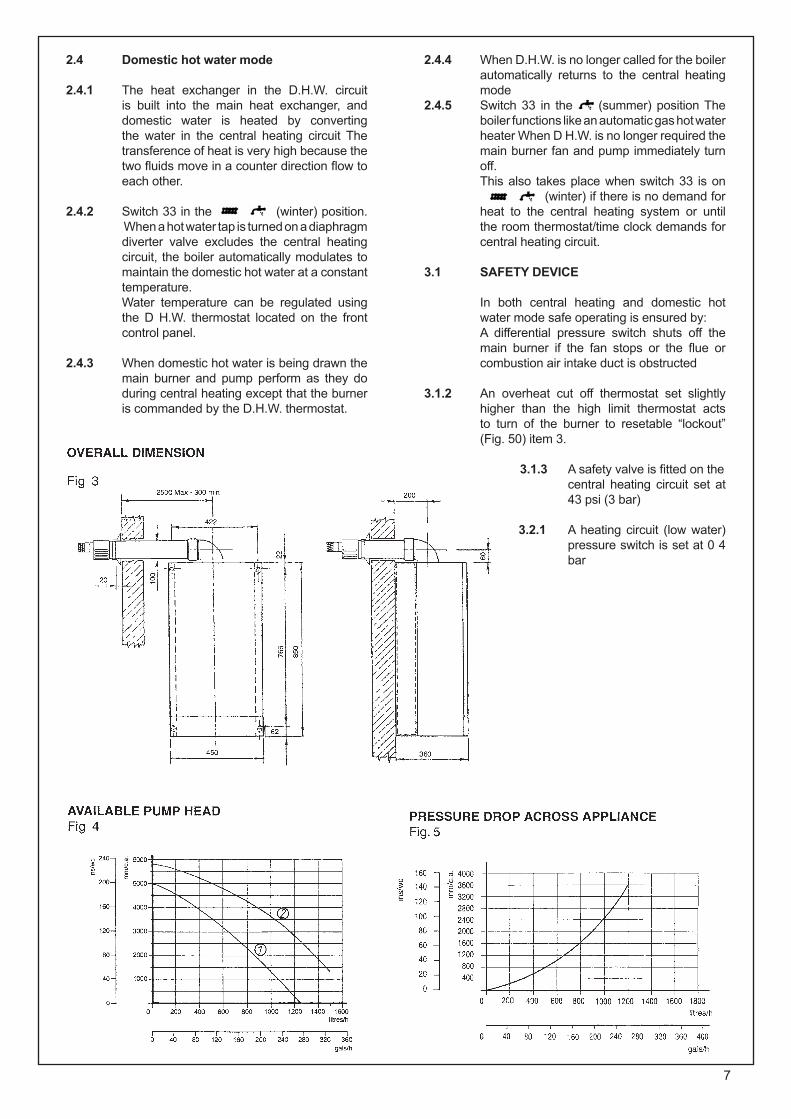
2.4 Domestic hot water mode
2.4.1 The heat exchanger in the D.H.W. circuit is built into the main heat exchanger, and domestic water is heated by converting the water in the central heating circuit The transference of heat is very high because the two fluids move in a counter direction flow to each other.
2.4.2 Switch 33 in the (winter) position. When a hot water tap is turned on a diaphragm
diverter valve excludes the central heating circuit, the boiler automatically modulates to maintain the domestic hot water at a constant temperature.
Water temperature can be regulated using the D H.W. thermostat located on the front control panel.
2.4.3 When domestic hot water is being drawn the main burner and pump perform as they do during central heating except that the burner is commanded by the D.H.W. thermostat.
2.4.4 When D.H.W. is no longer called for the boiler automatically returns to the central heating mode
2.4.5 Switch 33 in the (summer) position The boiler functions like an automatic gas hot water heater When D H.W. is no longer required the main burner fan and pump immediately turn off.
This also takes place when switch 33 is on (winter) if there is no demand for
heat to the central heating system or until the room thermostat/time clock demands for central heating circuit.
3.1 SAFETY DEVICE In both central heating and domestic hot
water mode safe operating is ensured by: A differential pressure switch shuts off the
main burner if the fan stops or the flue or combustion air intake duct is obstructed
3.1.2 An overheat cut off thermostat set slightly higher than the high limit thermostat acts to turn of the burner to resetable “lockout” (Fig. 50) item 3.
3.1.3 A safety valve is fitted on the
central heating circuit set at 43 psi (3 bar)
3.2.1 A heating circuit (low water) pressure switch is set at 0 4 bar
8
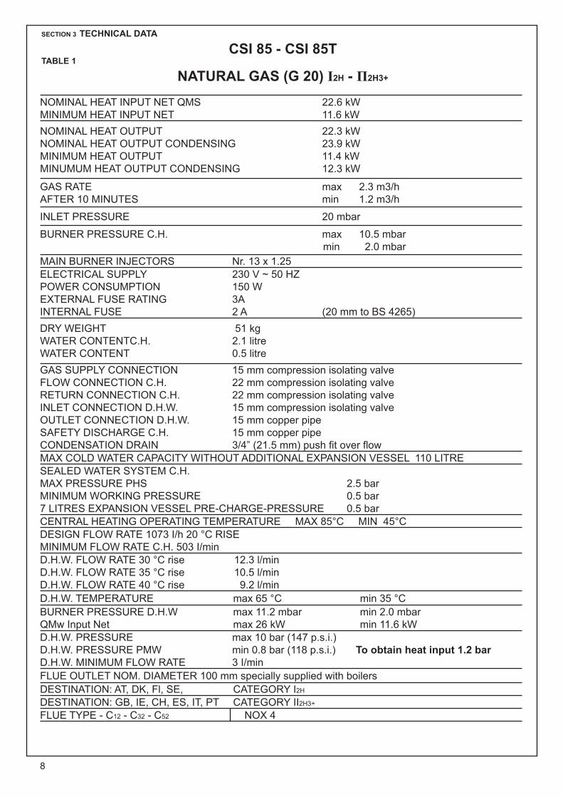
NOMINAL HEAT INPUT NET QMS 22.6 kWMINIMUM HEAT INPUT NET 11.6 kWNOMINAL HEAT OUTPUT 22.3 kWNOMINAL HEAT OUTPUT CONDENSING 23.9 kWMINIMUM HEAT OUTPUT 11.4 kWMINUMUM HEAT OUTPUT CONDENSING 12.3 kW
GAS RATE max 2.3 m3/hAFTER 10 MINUTES min 1.2 m3/h
INLET PRESSURE 20 mbar
BURNER PRESSURE C.H. max 10.5 mbarmin 2.0 mbar
MAIN BURNER INJECTORS Nr. 13 x 1.25ELECTRICAL SUPPLY 230 V ~ 50 HZPOWER CONSUMPTION 150 WEXTERNAL FUSE RATING 3A INTERNAL FUSE 2 A (20 mm to BS 4265) DRY WEIGHT 51 kg WATER CONTENTC.H. 2.1 litre WATER CONTENT 0.5 litreGAS SUPPLY CONNECTION 15 mm compression isolating valveFLOW CONNECTION C.H. 22 mm compression isolating valveRETURN CONNECTION C.H. 22 mm compression isolating valveINLET CONNECTION D.H.W. 15 mm compression isolating valveOUTLET CONNECTION D.H.W. 15 mm copper pipeSAFETY DISCHARGE C.H. 15 mm copper pipeCONDENSATION DRAIN 3/4” (21.5 mm) push fit over flowMAX COLD WATER CAPACITY WITHOUT ADDITIONAL EXPANSION VESSEL 110 LITRE SEALED WATER SYSTEM C.H. MAX PRESSURE PHS 2.5 barMINIMUM WORKING PRESSURE 0.5 bar7 LITRES EXPANSION VESSEL PRE-CHARGE-PRESSURE 0.5 barCENTRAL HEATING OPERATING TEMPERATURE MAX 85°C MIN 45°CDESIGN FLOW RATE 1073 I/h 20 °C RISE MINIMUM FLOW RATE C.H. 503 I/minD.H.W. FLOW RATE 30 °C rise 12.3 l/minD.H.W. FLOW RATE 35 °C rise 10.5 l/minD.H.W. FLOW RATE 40 °C rise 9.2 l/minD.H.W. TEMPERATURE max 65 °C min 35 °CBURNER PRESSURE D.H.W max 11.2 mbar min 2.0 mbarQMw Input Net max 26 kW min 11.6 kWD.H.W. PRESSURE max 10 bar (147 p.s.i.) D.H.W. PRESSURE PMW min 0.8 bar (118 p.s.i.) To obtain heat input 1.2 barD.H.W. MINIMUM FLOW RATE 3 I/min FLUE OUTLET NOM. DIAMETER 100 mm specially supplied with boilers DESTINATION: AT, DK, Fl, SE, CATEGORY I2H
DESTINATION: GB, IE, CH, ES, IT, PT CATEGORY II2H3+
FLUE TYPE - C12 - C32 - C52 NOX 4
SECTION 3 TECHNICAL DATA
CSI 85 - CSI 85TTABLE 1
NATURAL GAS (G 20) І2H - П2H3+

9
NOMINAL HEAT INPUT NET QMS 22.6 kWMINIMUM HEAT INPUT NET 11.6 kW
NOMINAL HEAT OUTPUT 22.3 kWNOMINAL HEAT OUTPUT CONDENSING 23.9 kWMINIMUM HEAT OUTPUT 11.4 kWMINUMUM HEAT OUTPUT CONDENSING 12.3 kWGAS RATE max G31 0.9 m3/h G30 0.7 m3/hAFTER 10 MINUTES min 0.4 m3/h 0.3 m3/h
INTERNAL PRESSURE G31 37mbar G30 28-30 mbar
BURNER PRESSURE C.H. max G31 35.4mbar G30 27.3 mbarmin 7.3 mbar 7.0 mbar
MAIN BURNER INJECTORS Nr 13 x 0.75ELECTRICAL SUPPLY 230 V ~ 50 HZPOWER CONSUMPTION 150 WEXTERNAL FUSE RATING 3A INTERNAL FUSE 2 A (20 mm to BS 4265) DRY WEIGHT 51 kg WATER CONTENTC.H. 21 litre WATER CONTENT 05 litreGAS SUPPLY CONNECTION 15 mm compression isolating valveFLOW CONNECTION C.H. 22 mm compression isolating valveRETURN CONNECTION C.H. 22 mm compression isolating valveINLET CONNECTION D.H.W. 15 mm compression isolating valveOUTLET CONNECTION D.H.W. 15 mm compressionSAFETY DISCHARGE C.H. 15 mm copper pipeCONDENSATION DRAIN 3/4” (21.5 mm) push fit over flowMAX COLD WATER CAPACITY WITHOUT ADDITIONAL EXPANSION VESSEL 110 LITRE SEALED WATER SYSTEM C.H. MAX PRESSURE PHS 25 barMINIMUM WORKING PRESSURE 05 bar6 LITRES EXPANSION VESSEL PRE-CHARGE-PRESSURE 05 barCENTRAL HEATING OPERATING TEMPERATURE MAX 85°C MIN 35°CDESIGN FLOW RATE 1102 I/h 20 °C RISE MINIMUM FLOW RATE C.H. 503 I/minD.H.W. FLOW RATE 30 °C rise 12.3 l/minD.H.W. FLOW RATE 35 °C rise 10.5 l/minD.H.W. FLOW RATE 40 °C rise 9.2 l/min 10°C inlet temperatureD.H.W. TEMPERATURE max 65 °C min 35 °CBURNER PRESSURE DH.W max 35.4 (G31) mbar min 7.3 (G31)-7 (G30) Qmw Imput Net max 27.3 (G30) mbar min 11.6 kWD.H.W. PRESSURE max 10 bar (147 p.s.i.) D.H.W. PRESSURE PMW min 0.8 bar (11.8 p.s.i.) To obtain heat input 1.2 barD.H.W. MINIMUM FLOW RATE 3 I/min FLUE OUTLET NOM. DIAMETER 100 mm specially supplied with boilers DESTINATION: BE, FR CATEGORY I2H+
DESTINATION: GB, IE, CH, ES, IT, PT CATEGORY II2H3+
FLUE TYPE - C12 - C32 - C52 NOX 4
SECTION 3 TECHNICAL DATA
CSI 85 - CSI 85TTABLE 1/A
LPG (G 30 - G 31) І3+ - П2H3+

10
The manufacturer’s notes must NOT be taken, in any way, as overriding statutory obligations.
IMPORTANT: These appliances are CE certificated for
safety and performance. It is, therefore, important that no external control devices e.g. flue dampers, economisers etc., are directly connected to this appliance unless covered by these Installation and Service Instructions or as otherwise recommended by Ravenheat in writing. If in doubt please enquire.
Any direct connection of a control device not approved by Ravenheat could invalidate the certification and the normal appliance warranty.
It could also infringe the Gas Safety regulations and the above regulations.
NOTE: The Ravenheat LITTLE STAR combination
boiler has been tested and examined by Advantica Technologies Ltd, and is certified to comply with PrEN 483 and BS EN 625.
Manufacturers instructions must NOT be taken in any way as overriding statutory obligations.
If in doubt on any point please consult Ravenheat Manufacturing Ltd.
4.2 LOCATION OF BOILER
4.2.1 Siting of Ravenheat Little Star Combi Boiler must be as follows.
The position of installation should be within the building, unless otherwise protected by a suitable enclosure.
Adequate space for installation, servicing and air circulation around boiler must be allowed for.
The Ravenheat LS 80 (T) and LS 100 (T) Combi Boiler must be fitted on a flat and vertical wall capable of adequately supporting the weight of the boiler and any ancillary equipment.
The appliance may be installed on a combustible wall subject to the requirements of the Local Authority and Building Regulations.
LPG versions of this appliance shall not be installed in cellars or basements.
4.3 CLEARANCES AROUND THE APPLIANCE
4.3.1 The following minimum free spaces, required for installation inspection and servicing, must be left aroundthe boiler
18 inches (450 mm) in front 5 inches (125 mm) above 6 inches (150 mm) below 0.2 inches (5 mm) on each side 1 inch (25 mm) in front when installed in a
cupboard.
SECTION 4 GENERAL REQUIREMENTS
4.0.1 SAFETY Gas Safety (Installation and Use)
Regulations, 1994 and amended 2000. It is law that all gas appliances are installed
and serviced by a CORGI registered installer in accordance with the above regulations and these installation instructions. All CORGI registered installers carry a CORGI I.D. card and have a registration number. Both should be recorded in your boiler log book. You can check your installer by calling CORGI direct on: 01256 732300. Failure to install appliances correctly could lead to prosecution. It is in your own interest, and that of safety, to ensure the law is complied with. Check the boiler and flue is the correct type for installation.
The installation of the boiler MUST be in accordance with the latest I.E.E. (BS 7671) Wiring Regulations, local building regulations, bye-laws of the local water authority, the building regulations and the Building Standards (Scotland) and any relevant requirements of the local authority.
4.1 GENERAL INFORMATION Both the user and the manufacturer rely
heavily on the installer, whose job it is to install the combination boiler and connect it to a correctly designed heating system. Acquaint yourself with the British Standards concerning installation requirements. If you need advice on any points your Ravenheat Technical Services Office would be pleased to help. It is recommended that tools suitable for brass fittings are used, and have a capability to accomodate hexagon sizes up to 50 mms.
CODES OF PRACTICE/Ref: Documents Detailed recommendations are contained in the
following British Standard Codes of Practice: BS.6891 Low pressure installation pipes. BS.6798 Installation of gas fired hot water boilers of rated input not exceeding 60 kW. BS.5449 Forced circulation hot water systems. BS.5546 Installation of gas hot water supplies domestic purposes (2ndFamily Gases). BS.5440: 1 Flues (for gas appliances of rated input not exceeding 60 kW).
BS.5440: 2 Ventilatio(for gas appliances of rated input not exceeding 60 kW).
DD 189: 1990 Discharge of condensate.
Health & Safety Document No.635 The Electricity at Work Regulations, 1989.
11
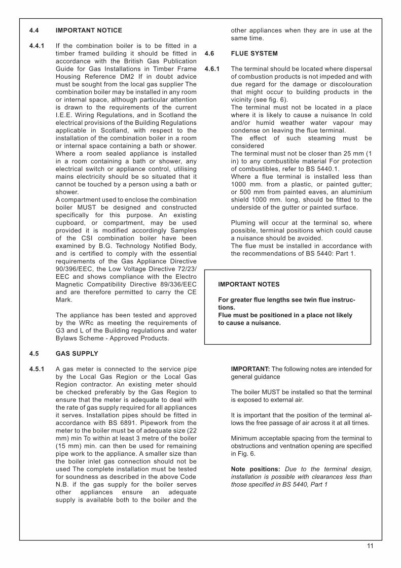
4.4 IMPORTANT NOTICE
4.4.1 If the combination boiler is to be fitted in a timber framed building it should be fitted in accordance with the British Gas Publication Guide for Gas Installations in Timber Frame Housing Reference DM2 If in doubt advice must be sought from the local gas supplier The combination boiler may be installed in any room or internal space, although particular attention is drawn to the requirements of the current I.E.E. Wiring Regulations, and in Scotland the electrical provisions of the Building Regulations applicable in Scotland, with respect to the installation of the combination boiler in a room or internal space containing a bath or shower. Where a room sealed appliance is installed in a room containing a bath or shower, any electrical switch or appliance control, utilising mains electricity should be so situated that it cannot be touched by a person using a bath or shower.
A compartment used to enclose the combination boiler MUST be designed and constructed specifically for this purpose. An existing cupboard, or compartment, may be used provided it is modified accordingly Samples of the CSI combination boiler have been examined by B.G. Technology Notified Body, and is certified to comply with the essential requirements of the Gas Appliance Directive 90/396/EEC, the Low Voltage Directive 72/23/EEC and shows compliance with the Electro Magnetic Compatibility Directive 89/336/EEC and are therefore permitted to carry the CE Mark.
The appliance has been tested and approved by the WRc as meeting the requirements of G3 and L of the Building regulations and water Bylaws Scheme - Approved Products.
4.5 GAS SUPPLY
4.5.1 A gas meter is connected to the service pipe by the Local Gas Region or the Local Gas Region contractor. An existing meter should be checked preferably by the Gas Region to ensure that the meter is adequate to deal with the rate of gas supply required for all appliances it serves. Installation pipes should be fitted in accordance with BS 6891. Pipework from the meter to the boiler must be of adequate size (22 mm) min To within at least 3 metre of the boiler (15 mm) min. can then be used for remaining pipe work to the appliance. A smaller size than the boiler inlet gas connection should not be used The complete installation must be tested for soundness as described in the above Code
N.B. if the gas supply for the boiler serves other appliances ensure an adequate supply is available both to the boiler and the
other appliances when they are in use at the same time.
4.6 FLUE SYSTEM
4.6.1 The terminal should be located where dispersal of combustion products is not impeded and with due regard for the damage or discolouration that might occur to building products in the vicinity (see fig. 6).
The terminal must not be located in a place where it is likely to cause a nuisance In cold and/or humid weather water vapour may condense on leaving the flue terminal.
The effect of such steaming must be considered
The terminal must not be closer than 25 mm (1 in) to any combustible material For protection of combustibles, refer to BS 5440.1.
Where a flue terminal is installed less than 1000 mm. from a plastic, or painted gutter; or 500 mm from painted eaves, an aluminium shield 1000 mm. long, should be fitted to the underside of the gutter or painted surface.
Pluming will occur at the terminal so, where
possible, terminal positions which could cause a nuisance should be avoided.
The flue must be installed in accordance with the recommendations of BS 5440: Part 1.
IMPORTANT NOTES
For greater flue lengths see twin flue instruc-tions.Flue must be positioned in a place not likely to cause a nuisance.
IMPORTANT: The following notes are intended for general guidance
The boiler MUST be installed so that the terminal is exposed to external air.
It is important that the position of the terminal al-lows the free passage of air across it at all tirnes.
Minimum acceptable spacing from the terminal to obstructions and ventnation opening are specified in Fig. 6.
Note positions: Due to the terminal design, installation is possible with clearances less than those specified in BS 5440, Part 1

12
Terminal position for fan assisted boiler(minimum distance) mmA - Directly below an open window or other 300 opening (e.g. air brick)B - Below gutters, soil pipes or drain pipes 25C - Below eaves 25D - Below balconies or car port roof 25E - From vertical drain pipes and soil pipes 25F - From internal or external corners 25G - Above ground or below balcony level 300H - From a surface facing a terminal 600I - From a terminal facing a terminal 1200 J - From an opening in the car port (e.g. door window) into dwelling. 1200K - Vertically from a terminal on the same wall 1500L - Horizontally from a terminal on the same wall 300
NOTE: The flue must be terminated in a place not likely to cause a nuisance.
4.6.2 A concentric vertical flue kit is available for flueing applications up to a maximum height of 4 metres.
For further details see vertical flue installation instructions.
4.7 AIR SUPPLY
4.7.1 The following notes are intended for general guidance.
The room sealed fan flued boiler does not require a permanent air vent for combustion air supply.
Where installed in a cupboard or compartment ventilation is not required.
4.8 WATER CIRCULATION (central heating)
4.8.1 Detailed recommendations are given in BS 6798:1987/5449:1990 (for smallbore and microbore central heating systems). The following notes are given for general guidance.
4.8.2 Pipework Copper tubing to BS 2871 1.1.1971 is
recommended for water pipes. Jointing should be either with capillary soldered or with compression fittings.
Where possible pipes should have a gradient to ensure air is carried naturally to air release points and water flows naturally to drain taps. It should be ensured as far as possible that the appliance heat exchanger is not a natural collecting point for air except where providing useful heat, pipes should be insulated to prevent heat loss and to avoid freezing. Particular attention should be paid to pipes passing through ventilated spaces in roofs and under floors.
4.8.3 The water through the appliance heat exchanger circuit must exceed the min. 2.38 gals/min. (650 It/h) when the burner is firing. It is important to ensure that this rate is achieved when sections of the system are shut off either manually or by automatic controls.
Therefore a by-pass must be fitted to the system (15 mm min.) (Fig. 6A).
If the volume of circulating water is too low, the boiler water temperature will rise too rapidly. This could cause noise in the system or even cause the safety thermostat to trip.

13
4.8.4 Draining tap These must be located in accessible positions
to permit the draining of the whole system. The taps must be at least 15 mm nominal size and manufactured in accordance with BS 2870 1980.
4.8.5 Air release points These must be fitted at all high points where
air will naturally collect, and must be sited to facilitate complete filling of the system.
4.8.6 The appliance has an integral sealed expansion vessel to accommodate the increase of water volume when the system is heated.
It can accept up to 6 Its of expansion water. If the appliance is connected to a system with an unusually high water content, calculate the total expansion and add additional sealed expansion capacity as appropriate (Fig. 7). In general, modern systems will present no problem.
4.8.7 Mains water feed: central heating There must be no direct connection to the
mains water supply, even through a nonreturn valve, without the approval of the Local Water Authority.
Figure 1 depicts the requirements of Diagram R24.2a of the Water Supply (Water Fittings) regulations 1999.

14
B) Where fitting of a make up vessel would be difficult, re pressurisation of the system can be done. See section on FILLING. If the capacity of the central heating system should exceed 85 litres, an additional vessel should be installed on the return to the combination boiler from the heating system (Fig. 7). Guidance on vessel sizing is given in Table 3.
Reference should be made to British Gas Publications ,Material and Installation Specifications for Domestic Central Heating and Hot Water». Draining taps should be at least 1/2” in BSP nominal size and be in accordance with BS 2879.
4.8.9 Installation to an existing central heating system
The combination boiler is designed to operate on a sealed system only. Therefore if the existing system is of the open water type it will have to be modified to comply with BS 5376 Part 2.
Before installing a new combination boiler to an existing system, flush out the old system with a recommended descaling agent.
It is most important that the correct concentration of the water treatment product is maintained in accordance with the manufacturers’ instructions.
If the boiler is installed in an existing system any unsuitable additives MUST be removed by thorough cleansing.
BS 7593:1992 details the steps necessary to clean domestic central heating system. Also check pipework and renew any corroded pipework or fittings. Valve glands must be repacked or replaced wherever necessary and any defective controls exchanged.
WATER TREATMENT This boiler has a secondary ALUMINIUM alloy
heat exchanger Ravenheat recommended only the use of FERNOX- COPAL or SENTINEL X100 water treatment products, which must be used in accordance with the manufacturers instructions. For further information contact:
Fernox Manufacturing Co. Ltd. Tel 01799 550811 Sentinel Division Betz Dearborn Ltd. Tel. (0151) 424 5351
Safetyvalve setting (bar) 3.0
Vessel chargepressure (bar) 0.5 1.0 1.5
Initial systempressure (bar) 0.5 1.0 1.5 2.0 1.0 1.5 2.0 1.5 2.0
Total watercontent of system EXPANSION VESSEL VOLUME (LITRES)
Litres
255075100125150175200225250275300325350375400425450475500
2.14.26.38.3
10.412.514.616.718.720.822.925.027.029.131 .233.335.437.539.641.6
3.57.0
10.514.017.521.024.528.031 .535.038.542.045.549.052.556.059.563.066.570.0
6.512.919.425.932.438.845.351 .858.364.771 .277.784.190.697 .1
103.6110.1116.5123.0125.9
13.727.541.355.168.982.696.4110.2124.0137.7151 .5165.3179 .1192.8206.6220.4239.2247.9261 .7275.5
2.75.48.2
10.913.616.319.121.824.527.230.032.735.738 .140.943.646.349.051 .854.5
4.79.5
14.219.023.728.533.238.042.747.552..257.061 .766.571 .276.080.785.590.295.0
10.320.630.941.251.561.872.182.492.7103.0113.3123.6133.9144.2154.5164.8175.1185.4195.7206.0
3.97.8
11.715.619.523.427 .331.235 .139.042.946.850.754.658.562.466.370.274.178.0
8.316.524.833.141.349.657.966.274.5
82.791.099.3
107.6115.8124.1132.4140.7148.9157.2165.5
For system volumesother than those givenabove, multiply thesystem volume bythe factor across
0.0833 0.140 0.259 0.551 0 .109 0.190 0.412 0.156 0.331
SIZING OF ADDITIONAL EXPANSION VESSEL: TABLE 3 Deduct from the value given in the table the 7 litre vessel supplied.
Note: This pressure can be increased up to 1.5 bar to suit high static head situations, see item 10, other appliance components in the SERVICING INSTRUCTIONS.

15
SALAMANDER CURROSION GUARD
Salamander (Eng) Ltd Tel: (0121) 3780952 /4508
4.8.10 Hard water areas If the area of installation is recognized as hard
water, it is recommended that a suitable water treatment device is installed in the mains.
The water hardness can be determined by using the standard test paper or by referring to local water authority.
4.9 DOMESTIC WATER
4.9.1 The domestic hot water must be in accordance with the relevant recommendations of BS 5546. Copper tubing to BS 2871 1 is recommended for water carrying pipework and MUST be used for pipework carrying potable water.
4.10 ELECTRICAL SUPPLY
Warning: this appliance must be earthed
4.10.1 External wiring to the appliance must be carried out by a competent person and be in accordance with the current I.E.E. Regulations and local regulations which apply. The Ravenheat boiler is supplied for connection to a 230 V - 50 Hz single phase supply. The supply must be fused at 3 A.
NOTE. The method of connection to the electricity supply MUST facilitate complete electrical isolation of the appliance, by the use of a fused, double pole isolator, having a contact separation of at least 3 mm in all poles. The point of connection to the electricity supply must be readily accessible and adjacent to the appliance except, where the appliance is installed in a bathroom, this MUST be sited outside the bathroom.
SECTION 5 INSTALLATION
5.1 WARNING
5.1.1 It is MOST IMPORTANT that this appliance is installed in a VERTICAL POSITION, with the flue air duct passing through the wall.
Make sure flue slopes 2.5° down towards the boiler that is 45 mm/m fall per metre of flue length.
16
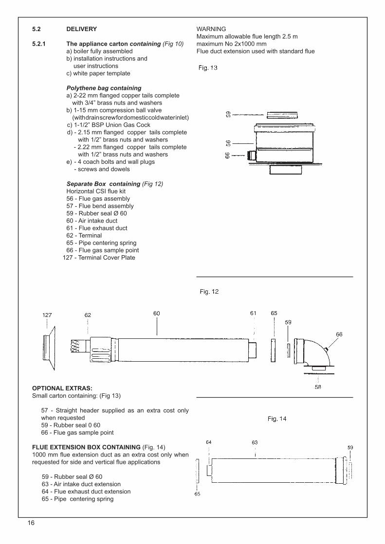
5.2 DELIVERY
5.2.1 The appliance carton containing (Fig 10) a) boiler fully assembled b) installation instructions and user instructions c) white paper template
Polythene bag containing a) 2-22 mm flanged copper tails complete
with 3/4” brass nuts and washers b) 1-15 mm compression ball valve
(with drain screw for domestic cold water inlet) c) 1-1/2” BSP Union Gas Cock
d) - 2.15 mm flanged copper tails complete with 1/2” brass nuts and washers
- 2.22 mm flanged copper tails complete with 1/2” brass nuts and washers
e) - 4 coach bolts and wall plugs - screws and dowels
Separate Box containing (Fig 12) Horizontal CSI flue kit 56 - Flue gas assembly 57 - Flue bend assembly 59 - Rubber seal Ø 60 60 - Air intake duct 61 - Flue exhaust duct 62 - Terminal 65 - Pipe centering spring 66 - Flue gas sample point 127 - Terminal Cover Plate
OPTIONAL EXTRAS:Small carton containing: (Fig 13)
57 - Straight header supplied as an extra cost only when requested59 - Rubber seal 0 6066 - Flue gas sample point
FLUE EXTENSION BOX CONTAINING (Fig. 14) 1000 mm flue extension duct as an extra cost only when requested for side and vertical flue applications
59 - Rubber seal Ø 6063 - Air intake duct extension64 - Flue exhaust duct extension65 - Pipe centering spring
WARNINGMaximum allowable flue length 2.5 mmaximum No 2x1000 mmFlue duct extension used with standard flue

17

18
5.4 POSITIONING OF THE BOILER
5.4.1 - Remove the 2 screws that secure the upper part of the front panel of the casing (Fig 19).
- Carefully slide the front panel a few millimetres up towards the top of the appliance until it is free from its slot, and then lift off (Fig. 20).
5.4.2 Unscrew the 2 screws that fasten the lower grating on the casing and remove it from the sides of the casing (Fig. 22)
5.4.3 Push down the 2 plastic clips that fasten the instrument panel (Fig. 23).
5.4.4 Lower the instrument panel down by rotating it on its own hinges (Fig. 25)
Unscrew the two screws fastening panels (Fig. 21).
5.4.5 Remove the two sides of the casing by slightly lifting them and carefully sliding towards the top of the appliance, to release them from their upper suspension hooks (Fig. 26-27)
5.4.6 Make sure the casing and screws are put to one side in a safe place.
5.5 INSTALLING THE APPLIANCE FOR REAR FLUE OUTLET
5.5.1 Use adhesive tape to attach the template to the wall, making sure that the centre line is vertical.- Mark the four boiler fastening holes on the
wall as well as the centre of the flue duct- Detach the template from the wall.- Use a 10 mm. dia drill to make the 4 boiler
securing holes. Insert the plastic expansion plugs.
- Cut or core drill a 105 mm. dia hole for inserting the flue duct- Screw in the two upper coach bolts leaving
them about 10 mm. out from the wall to enable the boiler to be located on the wall
Fit the elbow header positioning it towards therequired direction (Fig 30). IMPORTANT: Make sure that the elbow’s dia. 60 mm duct is inserted into the fan, the rubber seal and orifice (F2) have been correctly fitted.
19
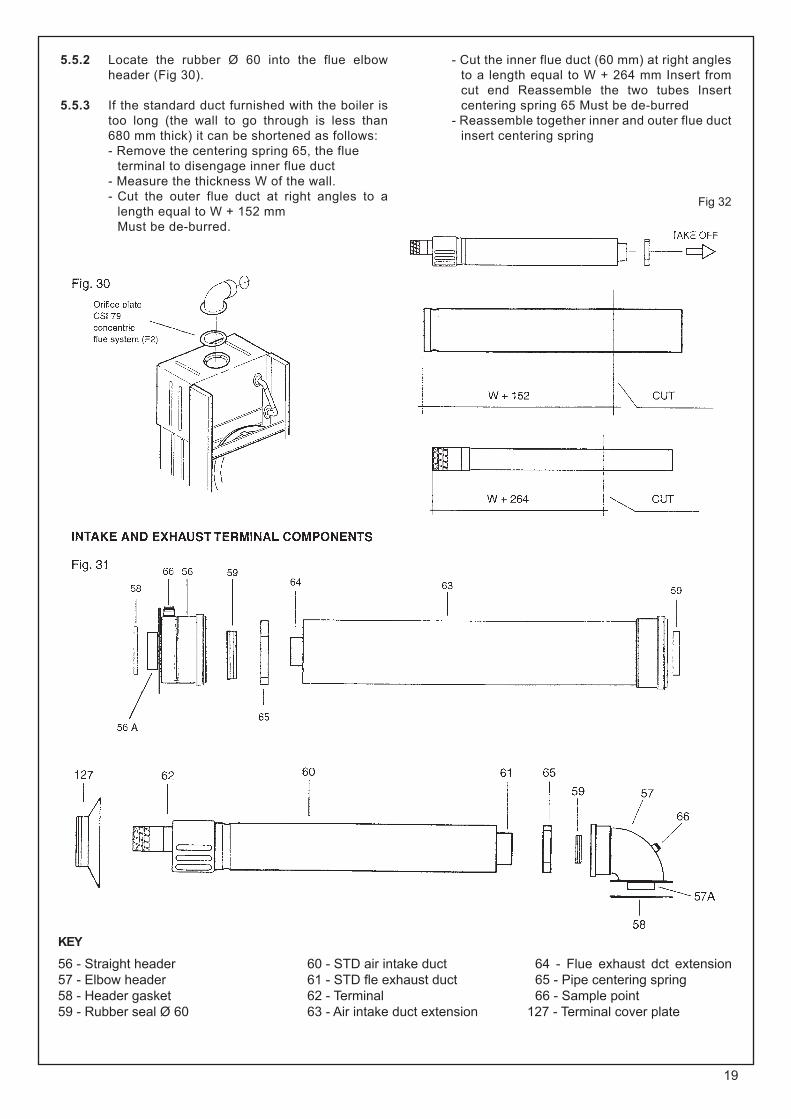
5.5.2 Locate the rubber Ø 60 into the flue elbow header (Fig 30).
5.5.3 If the standard duct furnished with the boiler is too long (the wall to go through is less than 680 mm thick) it can be shortened as follows:
- Remove the centering spring 65, the flueterminal to disengage inner flue duct
- Measure the thickness W of the wall.- Cut the outer flue duct at right angles to a
length equal to W + 152 mm Must be de-burred.
- Cut the inner flue duct (60 mm) at right angles to a length equal to W + 264 mm Insert from cut end Reassemble the two tubes Insert centering spring 65 Must be de-burred
- Reassemble together inner and outer flue duct insert centering spring
KEY
56 - Straight header57 - Elbow header58 - Header gasket59 - Rubber seal Ø 60
60 - STD air intake duct61 - STD fle exhaust duct62 - Terminal63 - Air intake duct extension
64 - Flue exhaust dct extension65 - Pipe centering spring66 - Sample point
127 - Terminal cover plate
Fig 32

20
5.5.4 Insert the flue assembly into the wall, being careful to make sure that the outer air duct comes flush to the inner surface of the wall
5.5.5 Lift the boiler on to the wall (Fig 34), locating onto the top coach bolts Fit the two lower coach bolts and tighten all four securing bolts.
5.5.6 Working above the boiler pull the flue exhaust duct towards the boiler in order to engage tube 61 into its header 57A. Position flue into elbow header and push so as to locate inner and outer flue correctly ensuring good seal is made with o rings.
5.5.4 Insert the flue assembly into the wall, being careful to make sure that the outer air duct comes flush to the inner surface of the wall
5.5.5 Lift the boiler on to the wall (Fig 34), locating onto the top coach bolts Fit the two lower coach bolts and tighten all four securing bolts.

21
5.5.10 Each extension length extends the pipe by approximately 1000 mm long up to a maximum of two extensions
Pipeline length can be established using the instructions in section 5.5 for rear flue outlets and section 5.7 for side flue outlets. Extensions must be installed with the widened end of the air intake pipe and the tapered end of the flue pipe aimed towards the exhaust terminal. Extensions must be joined together with the standard terminal pipe, and inserted in each other as far as they can go
If an extension must be shortened, this must be done from the straight end, and not from the widened or tapered end. To measure the pipeline properly all components must be assembled and total length measured before cutting. The straight end of the extension connects to the boiler. The flue output pipe fits into the boiler header until it stops. The air intake pipe should be located approximately 2 mm. from the boiler header (Fig. 31).
When cutting both inner and outer ducts of the extension, always ensure that the reduced end (male) of the inner duct is longer than the outer duct.
All joints must be sealed with the rubber seals supplied.
It is important to put the centering spacer, supplied with the unit, inside between the two pipes, from the side opposite the extension’s straight end.
NOTE: a suitable support bracket is available from Ravenheat Manufacturing and should be used to support flue length at least every 1.8 metre preferably at each joint this bracket should be secured to wall and flue duct.
5.5.11 INLINE FLUE BEND Measure the distance between the flue bends or
the flue/terminal assembly. The measurements should be taken from the outer edge of the flue and bend (Fig. 39B).
IMPORTANT: inline flue bend - 1680 mm must be deducted from overall length for each 900 bend. Obtuse flue bend - 1680 mm must be deducted from overall length for each 135° bend (Fig. 39B).
5.6 COMPLETING BOILER INSTALLATION
5.6.1 Reasscmbte the outer casing (sect 5.4) proceeding in this order 1)Fit the two sides.2)Refit the instrument panel in reverse order as insect. 5.4.4.3)Refit the lower grating (sect. 5.4)
5.7 INSTALLING THE APPLIANCE FOR SIDE FLUE OUTLET (Fig. 39)
5.7.1 - Attach the template to the wall with adhesive tape, making sure that the centre line is
vertical and that the distance from the centre line to the nearest side wall is not less than measurement in table 6.
- Mark the four boiler securing holes on the walland extend the axis of the flue duct hole to the side wall ensuring it is horizontal.
- Trace the centre of the flue duct hole measure distance F (table 6). From the corner of the wall (Fig. 28), measure the distance Y between the centre of flue duct hole to the corner Detach the template from wall.
- Use a dia. 10 mm. drill to make the 4 holes for securing the boiler. Insert the plastic expansion plugs. Core drill a 105 mm dia. hole in the side wall for inserting the flue duct.
TABLE 6
CSI
F = 200 mm G = 275 mm

22
5.7.2 Positioning the elbow towards the required direction (Fig. 30).
5.7.3 Locate the Ø 60 into the elbow (Fig. 30).
5.7.5 - If the standard duct furnished with the boiler is too long (position of the boiler from the wall to go through as illustrated in the drawing and wall thicknesses less than what was specified above) it can be shortened as follows: Fig 28-29-31-32 - Remove the centering spring 65, pull the flue terminal disengage inner flue duct. - Measure the thickness W of the wall.- Cut the outer air duct (100 mm. dia.) at right angles and to a length equal to W+Y - 47 mm. (Fig. 32) - Cut the inner flue duct (60 mm dia.) at right angles and to a length equal to W+Y + 65 mm.- Outer air duct and inner flue duct must be de-burred.
- Reassemble the two tubes. Insert centering spring 65.
5.7.6 Insert the flue assembly into the wall, making sure it will not interfere when fixing the boiler on the wall.
5.7.7 Lift the boiler on the wall. Locate onto the top coach bolts. Fit the lower coach bolts and tighten all four securing bolts.
5.7.8 Working above the boiler pull the flue duct towards the elbow in order to engage tube into its header (Fig. 35). Position flue into straight header and push so as to locate inner and outer flue correctly. Ensuring good seal is made with o.rings.
5.7.10 IMPORTANT: Terminal rubber must be fitted (Fig. 37).
5.7.11 Extension kits are available on order for flue extension of up to 2.5 metres total length (Fig. 31). For further details see sect 5.5.10.

23
5.7.12 VERTICAL FLUE INSTRUCTION ONLY
INLINE FLUE BEND - 1680 MM MUST BE DEDUCTED FROM OVERALL LENGTH FOR EACH 90° BEND OBTUSE FLUE BEND - 1680 MM MUST BE DEDUCTED FROM OVERALL LENGTH FOR EACH 135° BEND
The vertical flue kit is intended for use where a horizontal flue outlet is not possible or desired The vertical flue can be used either with a flat roof or a pitched roof (maximum pitch 60°) Where a straight vertical flue is not possible or desired, an offset vertical flue can be used in conjunction with a side horizontal flue extension piece and an inline 135°/90° flue bend (Fig. 41).
IMPORTANT NOTESFor greater flue lengths see
twin flue leaflet
POSITION MIN. DISTANCE mm
N above roof level (to base of terminal) 300P from adjacent wall to flue 300Q from internal corner to flue 300S from facing terminal 1,200 M horizontally from a vertical terminal to a wall 300
Before proceeding with installation check the contents of the RAVENHEAT VERTICAL FLUE KIT, comprising of the following pieces:
- 1 RAVENHEAT VERTICAL FLUE complete with terminal assembly (for vertical flue application).- Additional 1000 mm (approx) Flue Extension pieces as necessary, each extension is provided with flue centering bracket.- One box containing straight header with inlet and outlet sealing rings.
Proceed with installation as detailed in section 5 up to 5.5.1., ignoring all references to horizontal flue installations.
Use adhesive tape to attach the template to the wall, making sure that the centre line is vertical and that the flue centre line is virtually below the point at which the flue will exit the roof.
- Ensure that the maximum permissible flue length is not exceeded (Fig. 42).
- Mark the four boiler fastening holes on the wall.
- Detach the template from the wall.
- Use a 10 mm dia. drill to make the 4 boiler securing holes. Insert plastic expansion plugs (Fig. 29).
- Screw in the two upper coach bolts leaving them about 10 mm out from the wall to enable the boiler to be located on the wall.
- Position the straight header on the top of the appliance (Fig. 43) item 6, and ensure that the gasket is correctly fitted.
Important: Make sure that the flue header dia 60 mm duct is inserted.

24
Cut a 105 mm diameter hole through the ceiling and/or roof, at the point previously marked.
Fit a roof flashing sleeve (7 Fig. 43) to the roof, available from Ravenheat Manufacturing.
Insert the Vertical Flue terminal assembly through the flashing plate from the outside
Fix the appliance to the wall, locating onto the top coach bolts. Fit the two lower coach bolts and tighten all four securing bolts.
Measure the vertical distance between the top of the flue (Fig. 42) and the bottom of the flue terminal assembly (Fig. 41). The measurements should be taken from the outer diameter of the flue.NOTE: Where this length does not match any standard combination of the extensions, extension can be cut to the required length (Fig. 44).
When cutting both inner and outer ducts of the extension, always cut on spigot side, and they must be de-burred.
Starting at the appliance end, assemble the extension duct sections, making each inner and outer (flue) joint by inserting the spigot end into the socket end of the next tube, making sure the seal rings are correctly located (Fig. 44). Make sure that the entire flue is adequately supported Use at least one bracket for each extension used.
Ensure that all inner flue connections have a good fit/seal, and that the space clips in each extension are correctly positioned.
5.8 REASSEMBLE BOILER AS PER (sect. 5.6.1)
5.8.1 Fitting valve packRemove plastic caps from boiler connection and fit flanged copper tail and valves as per Fig. 46 using washers provided.
5.9 GAS CONNECTION (Fig. 46)
5.9.1 A minimum working gas pressure of 20 mbar (8 in w.g.) must be available at the boiler inlet at full flow rate (37 mbar for propane, 29 mbar for butane).
5.9.2 Fit gas service cock to the boiler via the union nut and connect gas pipe. Do not overtighten and use another spanner as a counter force to avoid straining internal connections.Important consult (sect 4.5.1). _
5.10 CENTRAL HEATING CONNECTION (Fig. 46)
5.10.1 Before any central heating connections are made to the boiler all system valves should be opened and the system thoroughly flushed out with cold water. - Connect the central heating return pipe
to the isolating cock marked CHR.- Connect the central heating flow pipe to
the isolating cock marked CHF- Pipe dimensions and positions are
marked on template supplied and fig. 45.

25
5.11 DOMESTIC HOT WATER (Fig. 46)
5.11.1 The domestic hot water circuit does not need a safety valve but it is essential to ensure that the pressure of the cold water supply does not exceed 10 bar. If in doubt it is advisable to install a pressure reducing valve The minimum pressure needed to operate the domestic hot water system is 0 5 bar with a flow of approx 3 Us per min. The regulator screw on the cold water outlet of the diverter valve may be adjusted to prevent excess volume flow (Fig. 53 COMMISSIONING SECTION) Flush out all foreign matter from the supply pipe before connecting to the appliance. - Connect the 15 mm. cold water pipe to the
stop cock to the appliance inlet marked DCW.
- Connect the 15 mm. hot water pipe with a suitable connection.
5.12 SAFETY VALVE DISCHARGE
5.12.1 The safety valve is located near the pump. It has a threaded outlet RC 1/2” (to 15 mm copper) to permit a discharge pipe to be connected. When connecting ensure the discharge pipe does not restrict access. The discharge should terminate facing downward exterior to the building in a position where discharging (possibly boiling water & steam) will not create danger or nuisance, in easily visible position, and not to cause damage to electrical components or wiring.
The discharge must not be over an entrance or a window or any other type of access
5.13 ELECTRICAL CONNECTIONS
5.13.1 IMPORTANT: Electricity supply must be as specified in clause (sect. 4 10)- When controls external to the appliance
are required, design of the external electrical circuits should be undertaken by a competent person. In accordance with the IEE wiring regulations.
It is essential that all external controls must be volt free.
Factory fitted internal wiring must not be disturbed when wiring external controls
- To gain access to the electrical box remove the front panel of the case as described in clauses (sect. 5.4.1) and the instrument panel as described in clauses (sect. 5.4.3).
- The terminals are easily visible on the front of the electronic control board (Fig. 48).
- Heat resistant flexible cable is fitted between the isolator and the terminal block A 3 core cable of 0.75 mm’ (24x0,2 mm) to BS 6500.
Make sure all wires to the appliance are routed away from sharp edges and hot surfaces.
The cable must be fastened with its cord anchorage and connected so that should the cable slip from the anchorage the current carrying conductors become taut before the earthing conductor. Securely tighten all terminal screws and arrange the cable with slack between the cord anchorage and the terminal block WARNING: If the supply cord is damaged, it must be replaced by a service engineer (supply cord available from Ravenheat Manufacturing Ltd).
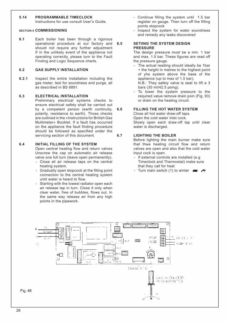
5.14 PROGRAMMABLE TIMECLOCK Instructions for use consult User’s Guide.
SECTION 6 COMMISSIONING
6.1 Each boiler has been through a rigorous operational procedure at our factory and should not require any further adjustment If in the unlikely event of the appliance not operating correctly, please turn to the Fault Finding and Logic Sequence charts.
6.2 GAS SUPPLY INSTALLATION
6.2.1 Inspect the entire installation including the gas meter, test for soundness and purge, all as described in BS 6891.
6.3 ELECTRICAL INSTALLATION Preliminary electrical systems checks to
ensure electrical safety shall be carried out by a competent person (earth continuity, polarity, resistance to earth). Those checks are outlined in the «Instructions for British Gas Multimeter» Booklet. If a fault has occurred on the appliance the fault finding procedure should be followed as specified under the servicing section of this document.
6.4 INITIAL FILLING OF THE SYSTEM Open central heating flow and return valves
Unscrew the cap on automatic air release valve one full turn (leave open permanently). - Close all air release taps on the central
heating system. - Gradually open stopcock at the filling point
connection to the central heating system until water is heard to flow.
- Starting with the lowest radiator open each air release tap in turn. Close it only when clear water, free of bubbles, flows out. In the same way release air from any high points in the pipework.
- Continue filling the system until 1.5 bar register on gauge. Then turn off the filling points stopcock
- Inspect the system for water soundness and remedy any leaks discovered
6.5 SETIING THE SYSTEM DESIGN PRESSURE
The design pressure must be a min. 1 bar and max. 1.5 bar. These figures are read off the pressure gauge.- The actual reading should ideally be 1bar
+ the height in metres to the highest point of yhe system above the base of the appliance (up to max of 1.5 bar).
N.B.: They safety valve is seat to lift a 3 bars (30 mt/42.5 psing).
- To lower the system pressure to the required value remove drain poin (Fig. 93) or drain on the heating circuit.
6.6 FILLING THE HOT WATER SYSTEM Close all hot water draw-off taps. Open the cold water inlet cock. Slowly open each draw-off tap until clear
water is discharged.
6.7 LIGHTING THE BOILER Before lighting the main burner make sure
that thwe heating circuit flow and return valves are open and also that the cold water input cock is open.- If external controls are installed (e.g
Timeclock and Thermostat) make sure that they call for heat
- Turn main switch (1) to winter
26
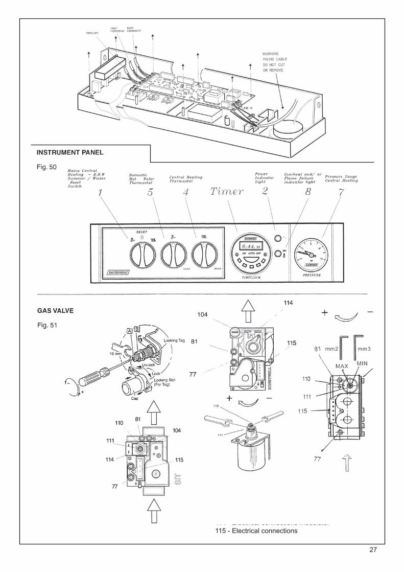
27
KEY77 - Upstream pressure inlet 81 - Downstream pressure outlet
104 - Gas valve modulator 110 - Max. regulator nut111 - Min. regulator nut 114 - Electrical connections modulator 115 - Electrical connections
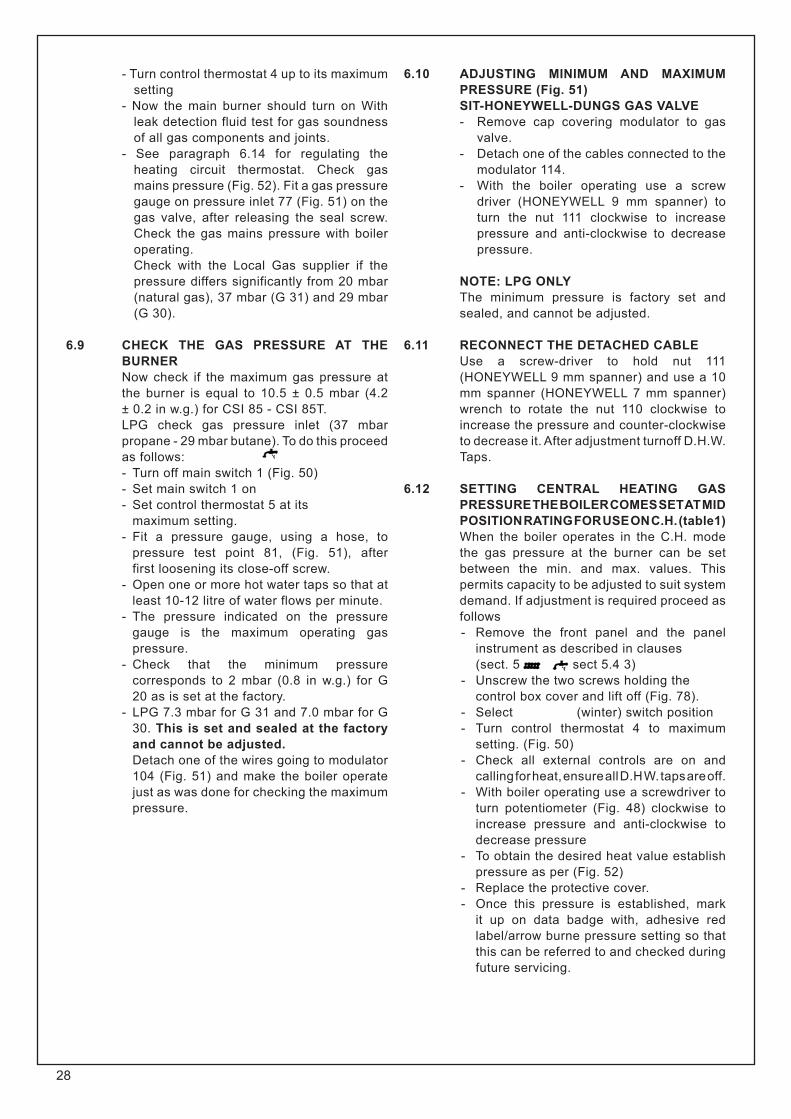
- Turn control thermostat 4 up to its maximum setting
- Now the main burner should turn on With leak detection fluid test for gas soundness of all gas components and joints.
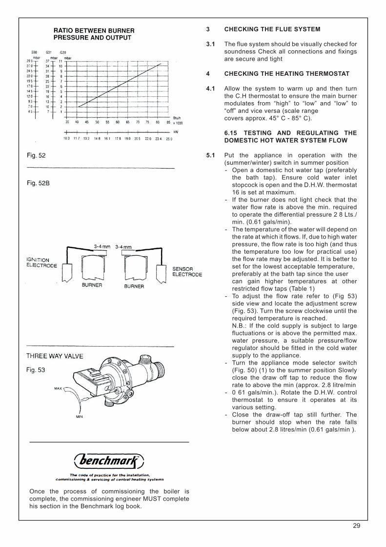
- See paragraph 6.14 for regulating the heating circuit thermostat. Check gas mains pressure (Fig. 52). Fit a gas pressure gauge on pressure inlet 77 (Fig. 51) on the gas valve, after releasing the seal screw. Check the gas mains pressure with boiler operating.
Check with the Local Gas supplier if the pressure differs significantly from 20 mbar (natural gas), 37 mbar (G 31) and 29 mbar (G 30).
6.9 CHECK THE GAS PRESSURE AT THE BURNER
Now check if the maximum gas pressure at the burner is equal to 10.5 ± 0.5 mbar (4.2 ± 0.2 in w.g.) for CSI 85 - CSI 85T.
LPG check gas pressure inlet (37 mbar propane - 29 mbar butane). To do this proceed as follows: - Turn off main switch 1 (Fig. 50)- Set main switch 1 on- Set control thermostat 5 at its maximum setting.- Fit a pressure gauge, using a hose, to
pressure test point 81, (Fig. 51), after first loosening its close-off screw.
- Open one or more hot water taps so that at least 10-12 litre of water flows per minute.
- The pressure indicated on the pressure gauge is the maximum operating gas pressure.
- Check that the minimum pressure corresponds to 2 mbar (0.8 in w.g.) for G 20 as is set at the factory.
- LPG 7.3 mbar for G 31 and 7.0 mbar for G 30. This is set and sealed at the factory and cannot be adjusted.
Detach one of the wires going to modulator 104 (Fig. 51) and make the boiler operate just as was done for checking the maximum pressure.
6.10 ADJUSTING MINIMUM AND MAXIMUM PRESSURE (Fig. 51)
SIT-HONEYWELL-DUNGS GAS VALVE- Remove cap covering modulator to gas
valve.- Detach one of the cables connected to the
modulator 114.- With the boiler operating use a screw
driver (HONEYWELL 9 mm spanner) to turn the nut 111 clockwise to increase pressure and anti-clockwise to decrease pressure.
NOTE: LPG ONLY The minimum pressure is factory set and
sealed, and cannot be adjusted.
6.11 RECONNECT THE DETACHED CABLE Use a screw-driver to hold nut 111
(HONEYWELL 9 mm spanner) and use a 10 mm spanner (HONEYWELL 7 mm spanner) wrench to rotate the nut 110 clockwise to increase the pressure and counter-clockwise to decrease it. After adjustment turnoff D.H.W. Taps.
6.12 SETTING CENTRAL HEATING GAS PRESSURE THE BOILER COMES SET AT MID POSITION RATING FOR USE ON C.H. (table1)
When the boiler operates in the C.H. mode the gas pressure at the burner can be set between the min. and max. values. This permits capacity to be adjusted to suit system demand. If adjustment is required proceed as follows- Remove the front panel and the panel
instrument as described in clauses (sect. 5.4.1 and sect 5.4 3)- Unscrew the two screws holding the control box cover and lift off (Fig. 78).- Select (winter) switch position - Turn control thermostat 4 to maximum
setting. (Fig. 50)- Check all external controls are on and
calling for heat, ensure all D.H W. taps are off.- With boiler operating use a screwdriver to
turn potentiometer (Fig. 48) clockwise to increase pressure and anti-clockwise to decrease pressure
- To obtain the desired heat value establish pressure as per (Fig. 52)
- Replace the protective cover.- Once this pressure is established, mark
it up on data badge with, adhesive red label/arrow burne pressure setting so that this can be referred to and checked during future servicing.
28
6.13 CHECKING THE FLUE SYSTEM
6.13.1 The flue system should be visually checked for soundness Check all connections and fixings are secure and tight
6.14 CHECKING THE HEATING THERMOSTAT
6.14.1 Allow the system to warm up and then turn the C.H thermostat to ensure the main burner modulates from “high” to “low” and “low” to “off” and vice versa (scale range
covers approx. 45° C - 85° C).
6.15 TESTING AND REGULATING THE DOMESTIC HOT WATER SYSTEM FLOW
6.15.1 Put the appliance in operation with the (summer/winter) switch in summer position- Open a domestic hot water tap (preferably
the bath tap). Ensure cold water inlet stopcock is open and the D.H.W. thermostat 16 is set at maximum.
- If the burner does not light check that the water flow rate is above the min. required to operate the differential pressure 2 8 Lts./min. (0.61 gals/min).
- The temperature of the water will depend on the rate at which it flows. If, due to high water pressure, the flow rate is too high (and thus the temperature too low for practical use) the flow rate may be adjusted. It is better to set for the lowest acceptable temperature,
preferably at the bath tap since the user can gain higher temperatures at other
restricted flow taps (Table 1)- To adjust the flow rate refer to (Fig 53)
side view and locate the adjustment screw (Fig. 53). Turn the screw clockwise until the required temperature is reached.
N.B.: If the cold supply is subject to large fluctuations or is above the permitted max. water pressure, a suitable pressure/flow regulator should be fitted in the cold water supply to the appliance.
- Turn the appliance mode selector switch (Fig. 50) (1) to the summer position Slowly close the draw off tap to reduce the flow rate to above the min (approx. 2.8 litre/min
- 0 61 gals/min.). Rotate the D.H.W. control thermostat to ensure it operates at its various setting.
- Close the draw-off tap still further. The burner should stop when the rate falls below about 2.8 litres/min (0.61 gals/min ).
Once the process of commissioning the boiler is complete, the commissioning engineer MUST complete his section in the Benchmark log book.
29

30
KEY
2 - Plenum chamber cover6 - Combustion chamber7 - Flue restriction ring8 - Flue gas exhaust hood
15 - Connection pipe 18 - Heat exchanger 24 - Burner
27 - Auto air vent valve 28 - Pressure switch 29 - Seal 31 - Seal 42- Sight glass 44 - Fan 46 - Header gasket 50 - Flue gas exhaust hood cover
53 - Connection tube 54 - Connection tube 58 - Ceramic insulation 61 - Condensing heat exchanger 80 - Plenum chamber 83 - Burner centering pin 84 - Seal
31
6.16 HANDING OVER TO THE USER
6.16.1 After completion of installation and commissioning of the system, the installer should hand over to the Householder by taking the following actions:
- Hand the “User’s Instructions” to the Householder and explain His/Her responsibilities under the “Gas Safety Regulations 2000”.- Explain and demonstrate the lighting and
shutting down procedures.- The operation of the boiler including the use
and adjustment of ALL system controls which should be fully explained to the Householder. This then ensures the greatest possible fuel economy consistent with household requirements of both heating and hot water consumptions.
Advise the User of the precautions necessary to prevent damage to the system, and to the building, in the event of the system remaining inoperative during frost conditions
- Explain the function and the use of the boiler it only/ (Summer/Winter)
and ON/OFF switch.- Explain and demonstrate the function of
time and temperature controls, neon lights radiator valves etc for the economic use of the system.
- If an optional time clock is fitted, then draw attention to the time clock User’s Instructions and hand them to the Householder
- Stress importance of regular servicing by a qualified Heating Engineer and that a comprehensive service should be carried out AT LEAST ONCE A YEAR
- Fill in the Benchmark log book and leave completed with the customer.
SECTION 7 SERVICING INSTRUCTIONS
Ravenheat are a member of the Benchmark initiative and fully supports the aims of the programme. Benchmark has instructed to improve the standards of installation and commissioning of central heating systems in the UK and to encourage in the regular servicing of all central heating systems to ensure safety and efficiency.
7.1 SERVICING
7.1.1 To ensure continued efficient operation of the appliance it is necessary to carry out servicing and cleaning at regular intervals.
The frequency of cleaning will depend upon the particular installation conditions and usage but in general, once year should be adequate.
WARNINGBefore the start of any servicing orreplacement of components alwaysisolate electricity supply to the applianceand always turn off the appliance gassupply at the gas service cock.
Data badge position-lower left hand sub frame.- The following notes apply to the appliance
and its controls but it should be remembered that attention must also be paid to the heating and hot water circuits with special attention to radiator valves, thermostats, clocks, leaking hot water taps etc.
- Where it is necessary to replace a gasket that relies on adhesive for securing - this adhesive will be supplied with the gasket as a spare item.
- In all cases prior to servicing, remove the outer case (sect. 5.4). Operate the appliance by turning the hot water services on to a high water flow, and observe the main burner.
- Check that the flame covers all the flame ports and is of a light blue colour. Yellow flames and excessive lifting of flames indicate poor combustion.
- IMPORTANT: After completing any servicing or replacement of gas carrying components it is essential that a test for gas soundness is always carried out along with functional checks in operation
7.2 TO INSPECT AND CLEAN THE APPLIANCE
7.2.1 Before carrying out cleaning operation, cover the electrical control panel with a piece of waterproof material to protect it from debris
7.2.2 Inspect the heat exchanger for any blockage. Deposits of any material should be brushed away using a soft brush.
NOTE: Do not use brushes with metallic bristles
7.2.3 Examine internal pipe-work connections and automatic air vent for any water leaks Rectify if necessary
7.2.4 Examine the combustion chamber insulating material and renew if damaged (sect 7 9)
7.2.5 Remove and examine the burner injector clean or renew, as necessary (sec. 7.12 & 7.14)
7.2.5.1 Inspect the burner and remove any deposit with a soft brush Check the electrodes for damage or deterioration, clean or renew as necessary Ensure that the spark gaps are correct to dimensions specified in sec. 7.15.

7.2.6 Inspect the secondary condensate heat exchanger. Deposits can be cleared by removing and flushing out the exchanger Inspect the siphonic condensate trap for a blockage Any deposits should be flushed out (Fig. 90)
7.2.6.1 To remove condensate trap (sect. 5.4). Pull forward the trap (Fig. 90)
Unscrew the earth wire, and the sensor. Replace in reverse order.
7.2.7 Examine the fan for any mechanical damage, check to ensure free running of the fan wheel. Clean the wheel if necessary with a soft brush. Check sealing gasket and renew if damaged (sect. 7.6).
7.2.8 Examine flue duct and flue hood and ensure that there is no obstruction. Examine the gasket at the entry into the flue duct.
7.2.9 It is essential that a good seal is made at the outlet to the fan, renew this gasket if there is any sign of damage or deterioration.
7.3 TO REMOVE/REPLACE THE FRONT PANEL OF THE CASING (Fig. 19 & 20)
7.3.1 Remove the 2 screws that secure the upper part of the front panel of the casing.
Lift the front panel few millimeters to the top, until it is free from the slot and remove panel
7.4 TO REMOVE/REPLACE THE COMBUSTION CHAMBER COVER
7.4.1 Remove the front casing panel (sect. 7.3).
7.4.2 Unscrew all the screws that fasten the cover to the chamber body and put them into a container so that they don’t get lost.
7.4.3 Detach the cover, being careful not to damage the seal.
7.4.4 Reassemble in reverse order. Ensure good seal of cover when
replacing.
7.6 TO REMOVE/REPLACE THE FAN ASSEMBLY (Fig. 58)
7.6.1 Remove front casing (sect. 7.3). Remove combustion chamber front cover
as in (sect. 7.4).
7.6.2 Disconnect the electrical connections from the fan motor.
7.6.4 Support the fan and remove the two fixing screws and bracket from the front of the flue hood. Carefully withdraw from condensing heat
exchanger then from the appliance.Place in a safe place until required Reassemble in reverse order. Ensure wires are connected correctly (Fig. 94)
7.6.5 TO REMOVE/REPLACE CONDENSING HEAT EXCHANGER FIG. 54-55
7.6.5.1 Remove front casing (sect. 7.3). Remove combustion chamber front cover
as in (sect 7.4). Remove lower grating by unscrewing the two screws (Fig. 21).
7.6.5.2 Close the ON/OFF valves for the heating. Drain the heating system from the drain point mounted system (Fig. 93).
7.6.5.3 Remove the fan (sect.? 6)
7.6.5.4 Disconnect 4 unions for the heating water pipelines (Fig. 54) and remove the two short pipes.
7.6.5.5 Remove screw holding heat exchanger to chamber. Disconnect condensing discharge pipe by pulling off the pushfit connector at top rear of boiler (Fig. 54).
7.6.5.6 Pull the heat exchanger down and slightly forward until it comes out of the connection from chamber (Fig. 55).
7.6.5.7 Replace in reverse order. Taking care to refit discharge pipe at rear.
IMPORTANT: When replacing heat exchanger new seals must be used.
7.7 TO REMOVE/REPLACE THE FLUE HOOD (FIG. 60)
7.7.1 Remove front casing (sect. 7.3). Remove combustion chamber front cover
as in (sect. 7.4).7.7.2 Remove the fan (sect. 7.6)
7.8.11 Remove condensing heat exchanger (sect. 7.6.5)
7.7.3 Remove the three screws on the front that fasten hood to the combustion chamber.
7.7.4 Remove the two screws at the rear of hood.
7.7.6 Replace in reverse order
7.8 TO REMOVE THE HEAT EXCHANGER (FIG. 62-63-64)
7.8.1 Remove front casing (sect 7.3). Remove combustion chamber front cover
as in (sect. 7;4). Remove the lower grating (sect.5.4.2)
Lower the instrument panel (sect. 5.4 3 & 4).
32

33
7.8.2 Remove the two sides of the casing by slightly lifting them and sliding them towards the top of the appliance, to release them from their upper suspension hooks
7.8.4 Remove the fan (sect. 7.6).
7.8.5 Remove condensing heat exchanger (sect. 7.6.5).
7.8.6 Remove the flue hood (sect. 7.7).
7.8.8 Remove the automatic air vent (Fig. 92).
7.8.9 Disconnect unions for two heating (right side of boiler) water pipelines (Fig. 62).
7.8.10 Unscrew the rings that fasten the heat exchanger to the combustion chamber.
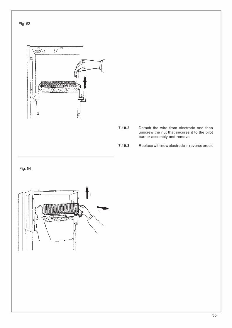
7.8.11 Remove the two side insulation panels at top of heat exchanger (Fig. 63).
7.8.12 Pull the heat exchanger up until its flow connections come out from the combustion chamber and then remove it (Fig. 64).
7.8.13 Replace in reverse order. Ensure correct wire position (Fig. 94).
IMPORTANT: When replacing a heat exchanger new seals must be used.
7.9 TO REMOVE/REPLACE COMBUSTION CHAMBER INSULATION PANELS
(Fig.63).
7.9.1 Remove casing front panel (sect. 7.3). Remove combustion chamber front cover
(sect. 7.4).
7.9.2 Remove fan (sect. 7.6).
7.9.3 Remove condensing heat exchanger (sect. 7.6.5).
7.9.4 Remove the flue hood (sect. 7.7).
7.9.5 Remove main burner (sect. 7.15). Remove top insulation pieces at sides.
Remove 2 screws securing combustion chamber to rear of boiler.
Lower chamber carefully remove all insulation panels.
7.9.6 Replace in reverse order.

34
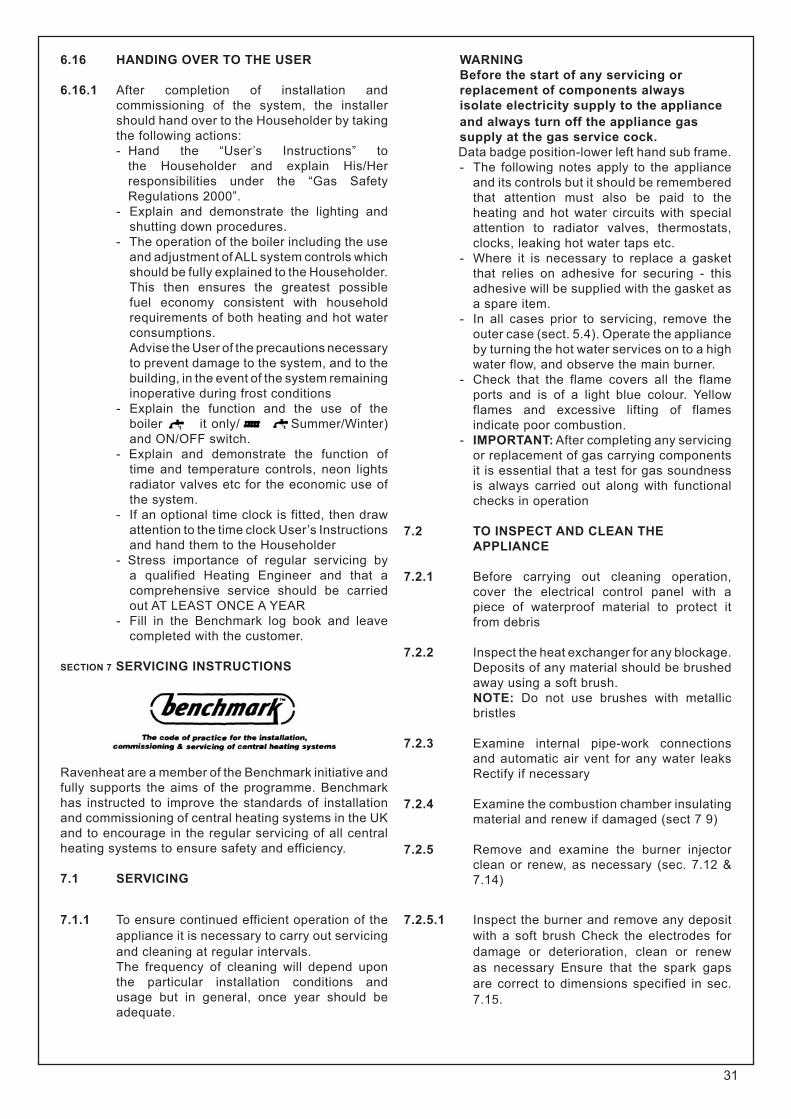
7.10 TO REPLACE THE ELECTRODE (Fig.52B)
7.10.1 Remove front casing (sect 7.3) Remove combustion chamber from cover
(sect 7.4)
35
7.10.2 Detach the wire from electrode and then unscrew the nut that secures it to the pilot burner assembly and remove
7.10.3 Replace with new electrode in reverse order.
36
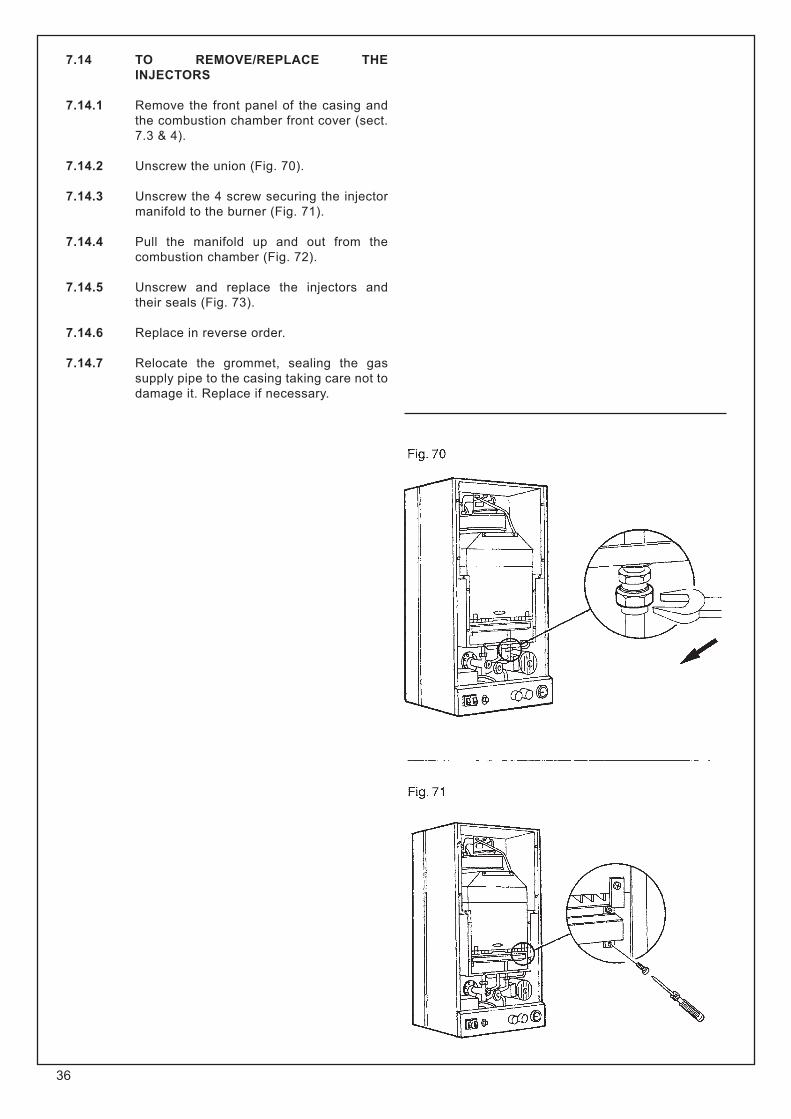
7.14 TO REMOVE/REPLACE THE INJECTORS
7.14.1 Remove the front panel of the casing and the combustion chamber front cover (sect. 7.3 & 4).
7.14.2 Unscrew the union (Fig. 70).
7.14.3 Unscrew the 4 screw securing the injector manifold to the burner (Fig. 71).
7.14.4 Pull the manifold up and out from the combustion chamber (Fig. 72).
7.14.5 Unscrew and replace the injectors and their seals (Fig. 73).
7.14.6 Replace in reverse order.
7.14.7 Relocate the grommet, sealing the gas supply pipe to the casing taking care not to damage it. Replace if necessary.
37
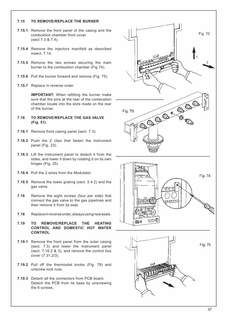
7.15 TO REMOVE/REPLACE THE BURNER
7.15.1 Remove the front panel of the casing and the combustion chamber front cover (sect 7.3 & 7.4).
7.15.4 Remove the injectors manifold as described insect. 7.14.
7.15.5 Remove the two screws securing the main burner to the combustion chamber (Fig 74).
7.15.6 Pull the burner forward and remove (Fig. 75).
7.15.7 Replace in reverse order.
IMPORTANT: When refitting the burner make sure that the pins at the rear of the combustion chamber locate into the slots made on the rear of the burner.
7.16 TO REMOVE/REPLACE THE GAS VALVE (Fig. 51)
7.16.1 Remove front casing panel (sect. 7 3).
7.16.2 Push the 2 clips that fasten the instrument panel (Fig. 23).
7.16.3 Lift the instrument panel to detach it from the sides, and lower it down by rotating it on its own hinges (Fig. 25)
7.16.4 Pull the 2 wires from the Modulator.
7.16.5 Remove the lower grating (sect. 5.4.2) and the gas valve.
7.16 Remove the eight screws (four per side) that connect the gas valve to the gas pipelines and then remove it from its seat.
7.16 Replace in reverse order, always using new seals.
7.19 TO REMOVE/REPLACE THE HEATING CONTROL AND DOMESTIC HOT WATER CONTROL
7.19.1 Remove the front panel from the outer casing (sect. 7.3) and lower the instrument panel (sect. 7.16.2 & 3), and remove the control box cover (7.31.2/3).
7.19.2 Pull off the thermostat knobs (Fig. 78) and unscrew lock nuts.
7.19.3 Detach all the connectors from PCB board. Detach the PCB from its base by unscrewing the 6 screws.

38
7.19.6 Replace in reverse order.
7.20 TO REMOVE/REPLACE THE MAIN SWITCH (Fig. 82).
7.20 Remove the front panel from the outer casing (sect. 7.3) and lower the instrument panel (sect. 7.16.2 & 3), and remove the control box cover (7.31.2/3).
7.20.2 Pull off the switch knob. Remove the switch out from the instrument panel by pressing the clamp springs (Fig. 82).
7.20.3 Detach the wires that connect to the switc make sure that these wires are later reconnected to the same poles (Fig. 94)
7.20.4 Replace in reverse order
7.21 TO REMOVE/REPLACE THE WATER PRESSURE GAUGE (Fig. 83).
7.21.1 Remove the front panel from the outer casing (sect. 7.3) and lower the instrument panel (sect. 7.16.2 & 3). Remove the lower grating (sect. 5.4.2).
7.21.2 Close the heating system on/off valves and drain the water from the drain point on the heating system (Fig 93).
7.21.3 Unscrew the fitting that secures the pressure gauge probe.
7.21.4 Remove the gauge from the instrument panel by pressing its fastening springs.
7.21.5 Replace in reverse order.
7.22 TO REMOVE/REPLACE THE OVERHEAT THERMOSTAT
7.22.1 Remove the front panel from the outer casing (sect 7.3).
7.22.4 Remove the two wires that connect to the overheat thermostat-making sure that these wires will subsequently be reconnected to the same poles (Fig. 94).
7.22.3 Replace in reverse order
7.23 TO REMOVE/REPLACE THE ELECTRIC CONTROL AND IGNITION BOARD
7.23.1 Remove the front panel from the outer casing (sect. 7.3) and lower the instrument panel
(sect. 1.16.2 & 3)
7.23.2 Unscrew the 2 screws holding the control box cover and remove.
Disconnect mains cables and any other connections (room thermostat and frost thermostat if fitted).
7.23.3 Detach the connectors from the board
7.23.5 Replace in reverse order (ensure all electrical connections are made correctly)
7.24 TO REMOVE/REPLACE THE DIFFERENTIAL PRESSURE SWITCH (Fig. 87).
7.24.1 Remove the front panel from the outer casing and the combustion chamber front cover (sect. 7.3 & 4).
7.24.2 Detach the wires that connect to the pressure switch, make sure that these wires are later reconnected to the same poles (Fig. 94).
7.24.3 Unscrew the two screws that fasten the pressure switch to the back of combustion chamber.
7.24.4 Remove the two silicone tubes.
7.24.5 Ensure tubes are connected correctly (Fig. 87) avoiding kinks.
7.24.6 Replace in reverse order ensuring that the tapping is connected to the tube terminating inside the case and the + tapping is connected to the tube terminating at flue ring
(Fig. 87 and 94)
7.25 TO REMOVE/REPLACE THE PUMP (Fig. 88)
7.25.1 Remove the front panel from the outer casing (sect. 7.3) and lower the instrument panel
(sect. 7.16.2 & 3)
7.25.2 Remove lower grill right side of the casing (sect. 5.4 2 & 5), lower the electric box
(sect. 7.16.2 & 3).

39
7.25.3 Close the on/off valves on the heating circuit and drain at drain point water from the boiler (Fig. 93).
7.25.4 Remove the wires that connect the pump (fig. 93).
7.25.5 Unscrew the two hexagonal nuts that fasten the pump to its pipes and remove the pump.
NOTE: It may be necessary to loosen the flow pipe at the heat exchanger to replace the pump gaskets.
7.25.6 Always use new seals when re-fitting the new pump.
7.25.7 Replace in reverse order
IMPORTANT:7.25.8 Make sure that the arrow that indicates the
direction of flow aims from the bottom upwards
7.25.10 Refill the heating system as described in the sect. 6.4 & 5 and check for leaks
7.26 TO REMOVE/REPLACE THE DIVERTER VALVE (Fig. 89)
7.26.1 Remove the front panel from the outer casing, lower the instrument panel (sect. 7.16 2 & 3).
Remove lower grating (sect. 5.4.2).
7.26.2 Close the on/off valves for the heating circuit and the hot water circuit. Drain the boiler at drain point (Fig. 93) and drain hot water from the lowest hot water tap and drain point on DHW inlet cock (Fig. 46).
7.26.4 Unscrew the five nuts that connect the diverter valve and pull it out from boiler being careful not to damage the wires.
7.26.5 Pull off circlip securing microswitches to divert-er valve
7.26.6 If replacing microswitch assembly use a screw-driver to prise off the protective cover of the microswitches.
7.26.7 Detach the wires that are connected to this. Remember that they must subsequently be reconnected to the same terminals (Fig. 94).
7.26.8 Replace in reverse order. Always use new seals.
7.26.9 Fill the boiler as described in (sect. 6.4 & 5) and check for leaks.
7.27 TO REMOVE/REPLACE THE CENTRAL HEATING AND/OR HOT WATER CONTROL THERMISTOR
7.27.1 Remove the front panel from theouter-cas-ing (sect. 7.3) and lower the instrument panel (sect. 7.16.2).
7.27.2 Remove left/right side of casing (sect. 5.4).
7.27.3 Remove the wires that connect the thermistor (Fig. 81).
7.27.4 Close the on/off valves for the heating circuit and the hot water circuit. Drain the boiler at drain point (Fig. 93) and drain hot water from the lowest hot water tap and drain point on DHW inlet cock (Fig. 46).

40
7.27.5 Undo the nut and withdraw the sensor (Fig. 81) from is pocket.)
7.27.6 Replace in reverse order.
7.28 TO REMOVE/REPLACE THE CENTRAL HEATING EXPANSION VESSEL
In the unlikely event of failure of the central heating expansion vessel it is recommended a suitable expansion vessel be fitted exter-nal to the boiler. It should be positioned on the return pipe and as close to the boiler as possible (Fig. 7). However, if it is necessary to replace the central heating expansion vessel the boiler must be removed from the wall as follows.
7.28.1 Remove the front panel from the outer casing (sect. 7.3) and lower the instrument panel (sect. 7.16.2 & 3) and remove the con-trol box cover (sect. 7.31.2/3). Remove the lower grating (sect. 5.4.2). Remove the two sides of the casing (sect. 5.4.5).
7.28.2 Close the on/off valve on the domestic cold water, central heating and gas supply.
7.28.3 Drain domestic water from the lowest hot wa-ter tap and drain point on DHW inlet cock (Fig. 46).
7.28.4 Drain the boiler (Fig. 93).
7.28.5 Disconnect all pipework connected to boiler.
7.28.7 Disconnect mains cables and any other con-nections (room thermostat, programming clock).
7.28.8 Remove the duct proceeding in reverse order as described in (sect. 5.5 or 5.7)
7.28.9 Remove the 2 lower coach bolts and release 2 top coach bolts then remove boiler from the wall.
7.28.10 Unscrew the nut that connects the expansion vessel and remove it (Fig. 91)
7.28.11 Remove the screw supporting expansion ves sel (Fig. 91).
7.28.12 Remove the expansion vessel.
7.28.13 Replace all the components in reverse order using new seals.
7.28.14 Fill the system as described in the sect. 6 and check for leaks.
7.29 TO REMOVE/REPLACE THE AUTOMATIC AIR VENT (Fig. 92)
7.29.1 Remove the front panel from the outer cas-ing and the combustion chamber front cover (sect. 7.3 & 4).
7.29.2 Remove the lower grating (sect. 5.4.2)
7.29.3 Remove the fan assembly and the flue hood (sect. 7.6 & 7 7).

41
7.29.4 Close the on/off valves for the central heating circuit and drain the water from the boiler drain point (Fig 93).
7.29.5 Unscerw and remove the plastic cap that protects the valve vent hole
7.29.6 Disconnect the unions 1 (Fig 92) slightly turn and remove auto air vent
7.29.7 Replace in reverse order, using new seals.
7.29.8 Fill the system as described in the sec. 6.4&5 and check for leaks
7.30 TO REMOVE/REPLACE THE PRESSURE RELIEF VALVE (Fig. 93)
7.30.1 Remove the front panel (sect. 7.3) and the lower grating (sect. 5.4.2) from the outer casing, lower the instrument panel (sect. 7.16.23) Remove right side of the casing (sect. 5.4.5)
7.30.2 Close the on/off valves for the heating system and drain the water from the drain point
7.30.3 Unscrew the screw from its body, clean or replace. Replace in reverse order
7.30.4 Fill the system as described in the (sect. 6.4 & 6.5)
7.31 TO REMOVE TIME CLOCK (Fig.88/A)
7.31.1 Remove the front panel from the outer casing (sect. 7.16.2 and 3).
7.31.2 Remove control box cover (Sect. 7.23.2).
7.31.3 Remove control board (Sect. 7.23.2) from panel
7.31.4 Remove two clips securing the timer.
7.31.5 Carefully remove the four wires connecting timer by pulling spade connectors from timer.
7.31.6 Replace in reverse order (ensure all electrical connections are made correctly)
(Fig. 88/A)
7.32 Replace in reverse order (ensure all electrical) connections are made correctly.

42
7.33 TO REMOVE / REPLACE D.H.W. HEAT EXCHANGER
7.33.1 Remove the front panel from the outer casing and lower the instrument panel (sect. 7.16.2 & 3)
7.33.2 Close the on/off valve may have to be remove for easier acces.
7.33.4 Unscrew the four nuts that connect the DHW heat exchanger and pull it out from boiler
7.33.5 If necessary the pipes from the diverter valve may have to be remove for easier access.
7.33.6 Repleace in reverse order Always use new seals.
7.33.7 Fill the boilers as described in (sect. 6.4 & 5) and check for leaks.

43

44
Is fan Running at
Maximum speed
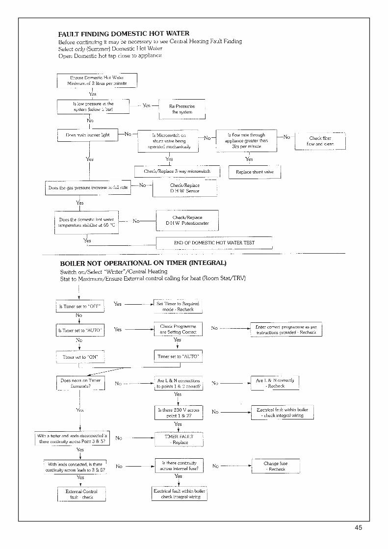
45

46
ETolleranze generali di lavorazione: UNI ISO 2768mk
DDENOMINAZIONE
CO
LLEG
AM
ENTO
ELE
TTR
ICO
CIR
CU
ITO
TEC
HN
OSY
STEM
P
ER
CA
LDA
IA C
SI8
5 M
OD
ULA
NTE
00
12IM
P06
006/
0C B A
CODICE
IMP
0600
6TAVOLA
GERBER
RV
DATA
MODIFICA
FIRMA
DISEGNATO TARGA
CONTROLLATO DURANTE
PAGINA
MATERIALE
SCALA
NOTE
0012
IMP
0600
6/0
DATA 06
/05/
2005

47
INSTALLATION iNSTRUCTION FOR TWIN FLUE PIPE (ECCENTRIC FLUE DUCT SYSTEM)
IMPORTANT These instructions must be read in conjunction with the main installation and servicing instructions
As with all flues the kits must be installed taking due account of the current issue of BS 5440 parts 1 & 2 and timber frame housing REF DM2 Also note that the requirements will vary depending upon the kit being installed. Guidance is provided but unless otherwise stated, always comply with the recommendations of the relevant codes of practice
8.1 TWIN FLUE INSTRUCTIONS This part of the installation manual covers the installation and fixing instructions of the twin flue eccentric flue duct systems only When ordering twin flue it must be stated for CSI range. Typical installation procedures are illustrated by drawings
IMPORTANTCorrect F1 orifice must be fitted.
Supplied with the CSI twin flue header is a F1 orifice plate along with supplementary depression sealBefore fixing the twin flue system the existing orifice plate must be replaced with F1 also ensuring supplementary seal has been fitted
Remove the 13 screws securing the depres-sion front panel item 2 figure 53A to expose front edge of depression chamber (Twin flue instructions figure 1 adjacent) Using adhesi-ve sponge supplied with CSI twin flue header, carefully attach to depression chamber so as to create a softer sealTaking care not to damage the new seal, carefully re-fit the depression chamber front cover in reverse order
Take out the 4 temporarily fitted securing screws, lifting our the gasket and orifice plate disconnecting it from the venturi tube.Discard this orifice plate and re-fit the F1 ori-fice plate ensuring that the venturi tube has been re-fitted, making sure this is securely lo-cated into the locating peg.
10 - air intake bend 90°
10 - flue exhaust bend 90°
11 - air inlet terminal
12 - flue exhaust terminal
13- 45° air intake bend duct
13 - 45° flue exhaust bend
14 - flue exhaust duct
14 - air intake duct
15 - two-way flue gas header
16 - vertical eccentric flue exhaust duct

48
Locate the sealing washer fixing the twin flue header as illustrated making sure that the ou-tlet spigot Make sure that the screws are satis- factorily located through the gasket seal.
Locate the 2 x 80 mm ‘O’ rings in the twin flue header.
Figures show the versatility of this flueing system. Measurements and bends must be calculated correctly so as not to oversize maximum flue len-gths.
All located ‘O’ rings must be lubricated with a silicone grease to ensure easy, snug fit.
NOTE: Exhaust flue must slope 2° down towards the boiler 35 mm fall per metre.
Spacing ClipsSpacing Clips are available on request should they be required.NOTE: for eccentric vertical flue a 125 mm (5 in) diameter flashing plate will be required.
Exhaust/suction system with concentric pipes for flat or sloping roofs. Extensions with two separate pipes.
Maximum distance = I + E + T = 2 Metre + 2 Metre + 1 Metre = 12 Metre maximum (pipe + terminal). Minimum distance D = T = 2 metre.
Exhaust terminal must not be cut
NOTE- The pressure loss for each elbow fitted is:
900 slow bend less 3 metre of pipe for each one fitted.135° bend less 1.5 metre of pipe for each one fitted.
NOTE:If bends are used in the exhaust flue then horizontal sections must be avoided and there must be a 2° slope towards the boiler 35 mm fall per metre.
IMPORTANT: See Fig. 42 for terminal clearances.
E = EXHAUST I = INLET T= TERMINAL
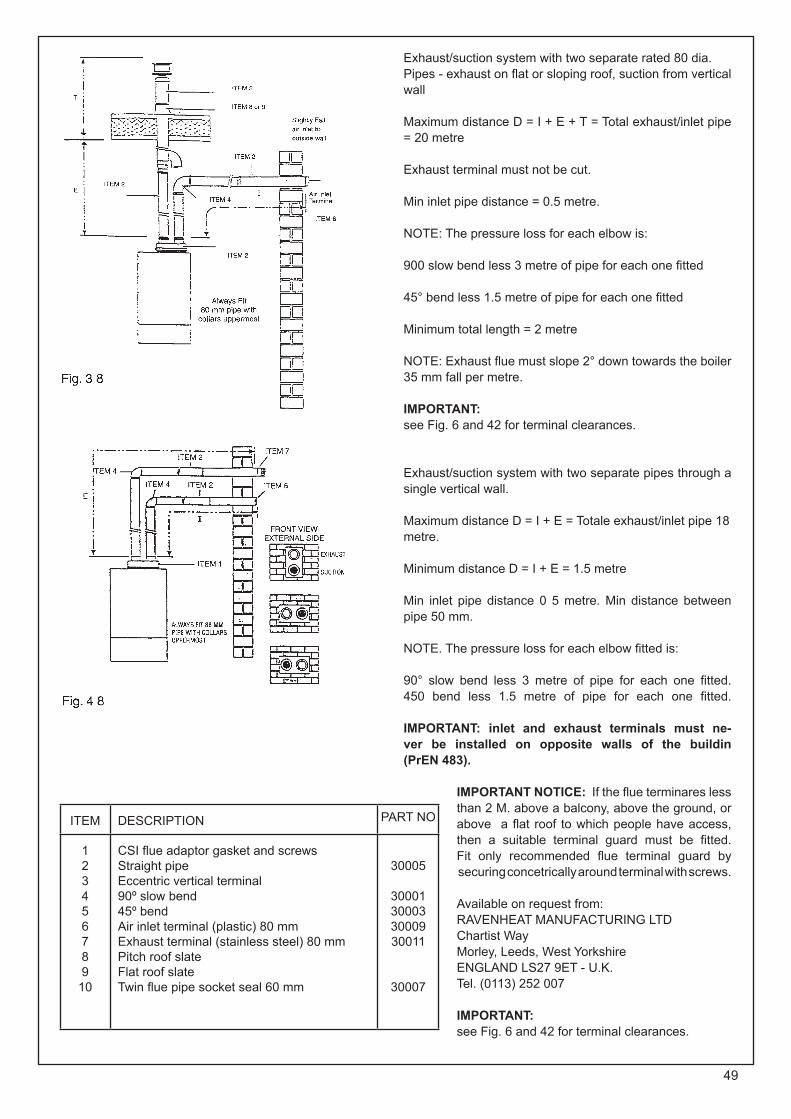
49
Exhaust/suction system with two separate rated 80 dia. Pipes - exhaust on flat or sloping roof, suction from vertical wall
Maximum distance D = I + E + T = Total exhaust/inlet pipe = 20 metre
Exhaust terminal must not be cut.
Min inlet pipe distance = 0.5 metre.
NOTE: The pressure loss for each elbow is:
900 slow bend less 3 metre of pipe for each one fitted
45° bend less 1.5 metre of pipe for each one fitted
Minimum total length = 2 metre
NOTE: Exhaust flue must slope 2° down towards the boiler 35 mm fall per metre.
IMPORTANT:see Fig. 6 and 42 for terminal clearances.
Exhaust/suction system with two separate pipes through a single vertical wall.
Maximum distance D = I + E = Totale exhaust/inlet pipe 18 metre.
Minimum distance D = I + E = 1.5 metre
Min inlet pipe distance 0 5 metre. Min distance between pipe 50 mm.
NOTE. The pressure loss for each elbow fitted is:
90° slow bend less 3 metre of pipe for each one fitted. 450 bend less 1.5 metre of pipe for each one fitted.
IMPORTANT: inlet and exhaust terminals must ne-ver be installed on opposite walls of the buildin(PrEN 483).
IMPORTANT NOTICE: If the flue terminares less than 2 M. above a balcony, above the ground, or above a flat roof to which people have access, then a suitable terminal guard must be fitted.Fit only recommended flue terminal guard by securing concetrically around terminal with screws.
Available on request from:RAVENHEAT MANUFACTURING LTDChartist WayMorley, Leeds, West Yorkshire ENGLAND LS27 9ET - U.K.Tel. (0113) 252 007
IMPORTANT:see Fig. 6 and 42 for terminal clearances.
ITEM DESCRIPTION PART NO
123456789
10
CSI flue adaptor gasket and screwsStraight pipeEccentric vertical terminal90º slow bend45º bendAir inlet terminal (plastic) 80 mmExhaust terminal (stainless steel) 80 mmPitch roof slateFlat roof slateTwin flue pipe socket seal 60 mm
30005
30001300033000930011
30007

50
15

51
RAVENHEAT CSI 85 - CSI 85 CONDENSING FANNED COMBI BOILER
SHORT LIST OF SPARE PARTS
Ravenheat G.C.Pos. Part. No. Part. No. Description
1 0014FR006005/2 Instrument panel - TIMER MODEL2 0012COM06005/0 E23-712 Main switch4 0012POT05010/0 E23-729 D.H.W. / C.H. Potentiometer5 0007TER08010/0 Overheat thermostat6 0001 CAM06005/0 E23-732 Combustion chamber7 0001 DIA06005/0 E23-730 Flue restriction ring 79CSI (F2)8 5027055 372842 Water gauge9 0007TER05005/0 E23-715 D.H.W. Sensor9.1 0007TER05006/0 CHSensor10 0014SPI09005/0 SIight glass11 0010TUB05041/0 Depression chamber gas pipe13 0001 CAP06005/0 E23-733 Flue gas exhaust hood15 0012CIR06010/0 FanControl Board16 0012CIR05010/2 Printed ignition control board17 0014MAN06015/0 E23-718 Knob21 0001C0P01010/0 Combustion chamber cover22 0008VAL09015/0 Dungs valve gas26 0002SCA06010/0 E23-731 Heat exchanger27 0014RAC06005/0 E23-735 Condensing trap28 0014REGO1005/0 371271 Water flow regulator29 0010TUB06050/1 Connecting pipe to air purge30 0008VAL01011/0 Air purge valve31 5018025 372851 Gasket 18.5 x 11.6 x 232 5018030 372867 Gasket 24 x 15 x 233 0012VEN03005/1 Fan36 5018046 378864 Gasket 30 x 22 x 237 1015PAN06005/0 E23-737 Insulation pads set 39 0012FUS05015/0 E23-720 Internal fuse 2A45 372855 46 0014GUA01020/0 371277 Flue gasket

52
Ravenheat G.C. Pos. Part. No. Part. No. Description 47 0001 CAM06010/0 Depression chamber50 0012CAN09005/2 Ignition-sensing electrode51 001 2CAV08020/0 Cable for spark-sensing electrode61 0002SCA06006/0 Condensing heat exchanger62 0003UGE03005/0 371297 Nozzle Ø 1,25 for natural gas62.1 0003UGE01011 /0 E23-755 Nozzle DM 0.75 LPG64 0001TEL08005/0 Frame65 5018046 372864 Seal67 0010TUB06020/1 Connecting pipe D.H.W. outlet24 0003BRU06016/0 Burner natural gas24.1 0003BRU06017/0 Burner LPG69 0008VAL06010/0 372-895 3-way valve70 0013GUA03035/0 371273 Gasket 32 x 32 x 2 gas valve79 0005PRE05010/0 371310 Low water pressure switch80 0009CIR01011/1 Circulation pump82 0011COL01005/2 Brass manifold83 0008VAL01018/1 Safety relief valve (3 bar)87 5021312 372875 Nylon tubes from pressure switch89 0005PRE06006/0 Pressure switch93 0019CUR06005/1 Elbow header95 0019PR005005/0 Flue extension duct complete97 0019TER06005/1 Flue duct and terminal complete100 0004VAS06010/0 Expansion tank105 TM6192 371258 Digital Timer106 0019TER06010/0 E23-753 Vertical Flue Terminal Complete110 0001 MAN05005/1 Bottom panel 112 0011RIV06007/0 Condensate blockage113 0012CAV06015/0 Earth wire114 0014GUA06010/0 Flue gasket dm 100115 0014GUA06005/0 Flue gasket dm 60116 0014GUA06015/0 Flue gasket dm 80117 0019SDO06005/0 Twin header118 0002SCA06015/1 Heat exchanger for D.H.W. water02 5012051 371257 Diaphragm for 3-way valve05 5012052 372899 Microswitch for 3-way valve
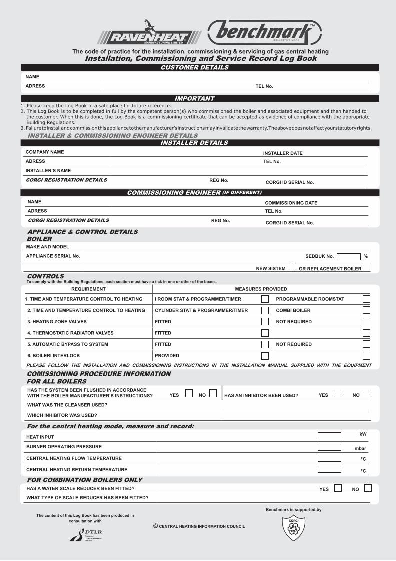
The code of practice for the installation, commissioning & servicing of gas central heatingInstallation, Commissioning and Service Record Log Book
NAME
ADRESS TEL No.
CUSTOMER DETAILS
IMPORTANT
COMPANY NAME INSTALLER DATEADRESS TEL No.
INSTALLER’S NAME
CORGI REGISTRATION DETAILS REG No. CORGI ID SERIAL No.
INSTALLER & COMMISSIONING ENGINEER DETAILS
NAME COMMISSIONING DATEADRESS TEL No.
CORGI REGISTRATION DETAILS REG No.
COMMISSIONING ENGINEER (IF DIFFERENT)
CORGI ID SERIAL No.
LOCATION
APPLIANCE & CONTROL DETAILS
%
MAKE AND MODEL APPLIANCE SERIAL No. SEDBUK No. %
BOILER
NEW SISTEM OR REPLACEMENT BOILER
For the central heating mode, measure and record:HEAT INPUT kW
BURNER OPERATING PRESSURE mbar
CENTRAL HEATING FLOW TEMPERATURE °C
CENTRAL HEATING RETURN TEMPERATURE °C
HAS A WATER SCALE REDUCER BEEN FITTED? YES NO
WHAT TYPE OF SCALE REDUCER HAS BEEN FITTED?
FOR COMBINATION BOILERS ONLY
HAS THE SYSTEM BEEN FLUSHED IN ACCORDANCEWITH THE BOILER MANUFACTURER’S INSTRUCTIONS? HAS AN INHIBITOR BEEN USED?
WHAT WAS THE CLEANSER USED?
WHICH INHIBITOR WAS USED?
FOR ALL BOILERS
YES NO YES NO
CONTROLSTo comply with the Building Regulations, each section must have a tick in one or other of the boxes.
REQUIREMENT MEASURES PROVIDED
1. TIME AND TEMPERATURE CONTROL TO HEATING I ROOM STAT & PROGRAMMER/TIMER PROGRAMMABLE ROOMSTAT
2. TIME AND TEMPERATURE CONTROL TO HEATING CYLINDER STAT & PROGRAMMER/TIMER COMBI BOILER
3. HEATING ZONE VALVES FITTED NOT REQUIRED
4. THERMOSTATIC RADIATOR VALVES FITTED
5. AUTOMATIC BYPASS TO SYSTEM FITTED NOT REQUIRED
6. BOILERI INTERLOCK PROVIDED
PLEASE FOLLOW THE INSTALLATION AND COMMISSIONING INSTRUCTIONS IN THE INSTALLATION MANUAL SUPPLIED WITH THE EQUIPMENT
The content of this Log Book has been produced in consultation with
© CENTRAL HEATING INFORMATION COUNCIL
COMISSIONING PROCEDURE INFORMATION
INSTALLER DETAILS
1. Please keep the Log Book in a safe place for future reference.2. This Log Book is to be completed in full by the competent person(s) who commissioned the boiler and associated equipment and then handed to
the customer. When this is done, the Log Book is a commissioning certificate that can be accepted as evidence of compliance with the appropriate Building Regulations.
3. Failure to install and commission this appliance to the manufacturer’s instructions may invalidate the warranty.The above does not affect your statutory rights.
Benchmark is supported by

GBLB
Sec
ond E
ditio
n
01.0
3.0
2
For the central hot water, measure and record:
HEAT INPUT kW
MAXIMUM BURNER OPERATING PRESSURE mbar
MAXIMUM OPERATING WATER PRESSURE bar
COLD WATER INLET TEMPERATURE °C
HOT WATER OUTLET TEMPERATURE °C
WATER FLOW RATE AT MAXIMUM SETTING Its/min
FOR CONDENSING BOILERS ONLYHAS THE CONDENSATE DRAIN BEEN INSTALLED IN ACCORDANCE WITH THE MANUFACTURER’S INSTRUCTIONS? YES NO
DOES THE HEATING AND HOT WATER SYSTEM COMPLY WITH THE APPROPRIATE BUILDING REGULATIONS?HAS APPLIANCE AND ASSOCIATED EQUIPMENT BEEN INSTALLED AND COMMISSIONED IN ACCORDANCE WITH THE MANUFACTURER’S INSTRUCTIONS?
HAVE YOU DEMONSTRATED THE OPERATION OF THE APPLIANCE AND SYSTEM CONTROLS TO THE CUSTOMER?
HAVE YOU LEFT ALL THE MANUFACTURER’S LITERATURE WITH THE CUSTOMER?
COMPETENT PERSON’S SIGNATURE CUSTOMER’S SIGNATURE
(To confirm demonstrations of equipment and receipt of appliance instructions)
FOR ALL INSTALLATION
SERVICE 4 DATE:ENGINEER NAME COMPANY NAME TEL No.CORGI ID CARD SERIAL No.COMMENTS
SIGNATURE
SERVICE 3 DATE:ENGINEER NAME COMPANY NAME TEL No.CORGI ID CARD SERIAL No.COMMENTS
SIGNATURE
SERVICE 2 DATE:ENGINEER NAME COMPANY NAME TEL No.CORGI ID CARD SERIAL No.COMMENTS
SIGNATURE
SERVICE 1 DATE:ENGINEER NAME COMPANY NAME TEL No.CORGI ID CARD SERIAL No.COMMENTS
SIGNATURE
SERVICE 5 DATE:ENGINEER NAME COMPANY NAME TEL No.CORGI ID CARD SERIAL No.COMMENTS
SIGNATURE
SERVICE 9 DATE:ENGINEER NAME COMPANY NAME TEL No.CORGI ID CARD SERIAL No.COMMENTS
SIGNATURE
SERVICE 8 DATE:ENGINEER NAME COMPANY NAME TEL No.CORGI ID CARD SERIAL No.COMMENTS
SIGNATURE
SERVICE 7 DATE:ENGINEER NAME COMPANY NAME TEL No.CORGI ID CARD SERIAL No.COMMENTS
SIGNATURE
SERVICE 6 DATE:ENGINEER NAME COMPANY NAME TEL No.CORGI ID CARD SERIAL No.COMMENTS
SIGNATURE
SERVICE 10 DATE:ENGINEER NAME COMPANY NAME TEL No.CORGI ID CARD SERIAL No.COMMENTS
SIGNATURE
SERVICE INTERVAL RECORDIt is recommended that your heating system is serviced regularly and that your service
engineer completes the appropriate Service Interval Record below.SERVICE PROVIDER
Before completing the appropriate Service Interval Record below, please ensure you have carried out the service as described in the boiler manufacturer’s instructions
and in compliance with The Gas Safety Regulations. Always use the appliance manufacturer’s specified spare part when replacing gas controls.
When all of the above services have been completed, please contact your Service Engineer for an additional service Interval record sheet.


COD 0017LIB06006/0 - 06/2005