COMSOL Multiphysics® Based Inductance Estimation for Modeling Transformer … · 2019-12-17 ·...
5
COMSOL Multiphysics® Based Inductance Estimation for Modeling Transformer Winding Faults in EMTP Hemanth Kumar Vemprala and Bruce A. Mork Dept. of Electrical and Computer Engineering, Michigan Technological University, Houghton, MI, USA Abstract- This work illustrates the modeling work performed to accurately estimate the parameters of Transformer leakage reactances used for analyzing transformer inner-winding faults. Internal faults such as Turn-to-Turn (T2T) and Turn-to-Ground (T2G) have been attributed to most transformer failures. The estimation of this faulted winding reactance using an analytical based approach is very intricate and the best parameter estimation was obtained from FEA. Using COMSOL Multiphysics® and internal modules, the estimated values for a range of fault location are analyzed and derived. These values are represented in the form of empirical curves which are then imported and processed in MATLAB to generate a user-defined library file for inclusion in EMTP simulation model. 1. Introduction Power Transformers are the most important element of power systems and protection from failures, especially from internal faults, has been a major challenge. The internal faults such as Turn-to- Turn (T2T) and Turn-to-Ground (T2G) have been attributed to most transformer failures. These faults typically evolve from a small winding fault to a full- blown large-magnitude fault current. Conventionally to study the transformer behavior under faulted condition, an EMTP environment is utilized. The leakage inductances for transformers are typically estimated using simplified approximation from traditional formula-based approaches but in the case of either T2T or T2G condition, the estimation becomes more tedious. The empirical curves generated from Derived Values are used to produce the inverse inductance matrix using Matlab scripts. These output library files are then exported to ATPDraw template of Hybrid transformer and used for studies in the EMTP environment such as energization, fault disturbance and cases for relay testing. The finite element model built for healthy and faulted (T2T or T2G) can be coupled with the electric circuit to simulate the comprehensive electric connection to validate the model in the FEM environment and to investigate the transformer model. The main objective of the work is to demonstrate that using COMSOL Multiphysics®, FEM based method can be implemented to build hybrid transformer models [3] with internal faults and overcome some of the serious limitations observed from the analytical approaches. The location of the faulted coil, configuration and number of turns are defined under Parameters node (Pi), Global definitions which plays a very vital role in automating the complex procedure. The Parametric Sweep in the Study node is also performed in continuity for studying the sensitivity of the coil inductance for a range of fault position on a certain coil. 2. Application of COMSOL Multiphysics ® The transformer model is built using the COMSOL Multiphysics® and an AC/DC module product. This module includes Maxwell’s formulations to solve AC and DC electromagnetics in either two or a three-dimensional workspace. Electric Currents (ec) and Magnetic Fields (mf) physics interface provide sufficient ability to realize the current goal. This section presents the case study for the need of FEA in the study and followed by the modeling approach for representing the transformer in healthy and under faulty condition. 2.1 Significance of FEA based approach Figure 1 presents the COMSOL simulation of the coil carrying 1A and the magnetic flux density and normalized magnetic field plotted. Figure 2 demonstrates a case of inductances estimated using different analytical approaches [1][2] for an air-core coil of varying breadth. The self-inductance of the coil is obtained from the global evaluation of the coil parameter mf.LCoil_1. Each of the analytical approach provide varying estimates for coil inductances as breadth of the coil varies. The case under study demonstrated is for an air core but for core with a ferromagnetic material, the approximation formula is much more intricate [7]. Excerpt from the Proceedings of the 2019 COMSOL Conference in Boston
Transcript of COMSOL Multiphysics® Based Inductance Estimation for Modeling Transformer … · 2019-12-17 ·...
COMSOL Multiphysics® Based Inductance Estimation for Modeling Transformer Winding Faults in EMTP
Hemanth Kumar Vemprala and Bruce A. Mork
Dept. of Electrical and Computer Engineering, Michigan Technological University,
Houghton, MI, USA Abstract-
This work illustrates the modeling work performed to accurately estimate the parameters of Transformer leakage reactances used for analyzing transformer inner-winding faults. Internal faults such as Turn-to-Turn (T2T) and Turn-to-Ground (T2G) have been attributed to most transformer failures. The estimation of this faulted winding reactance using an analytical based approach is very intricate and the best parameter estimation was obtained from FEA. Using COMSOL Multiphysics® and internal modules, the estimated values for a range of fault location are analyzed and derived. These values are represented in the form of empirical curves which are then imported and processed in MATLAB to generate a user-defined library file for inclusion in EMTP simulation model. 1. Introduction
Power Transformers are the most important element of power systems and protection from failures, especially from internal faults, has been a major challenge. The internal faults such as Turn-to-Turn (T2T) and Turn-to-Ground (T2G) have been attributed to most transformer failures. These faults typically evolve from a small winding fault to a full-blown large-magnitude fault current. Conventionally to study the transformer behavior under faulted condition, an EMTP environment is utilized. The leakage inductances for transformers are typically estimated using simplified approximation from traditional formula-based approaches but in the case of either T2T or T2G condition, the estimation becomes more tedious.
The empirical curves generated from Derived Values are used to produce the inverse inductance matrix using Matlab scripts. These output library files are then exported to ATPDraw template of Hybrid transformer and used for studies in the EMTP environment such as energization, fault disturbance and cases for relay testing. The finite element model built for healthy and faulted (T2T or T2G) can be coupled with the electric circuit to simulate the comprehensive electric connection to validate the model in the FEM environment and to investigate the
transformer model. The main objective of the work is to demonstrate that using COMSOL Multiphysics®, FEM based method can be implemented to build hybrid transformer models [3] with internal faults and overcome some of the serious limitations observed from the analytical approaches. The location of the faulted coil, configuration and number of turns are defined under Parameters node (Pi), Global definitions which plays a very vital role in automating the complex procedure. The Parametric Sweep in the Study node is also performed in continuity for studying the sensitivity of the coil inductance for a range of fault position on a certain coil.
2. Application of COMSOL Multiphysics ® The transformer model is built using the
COMSOL Multiphysics® and an AC/DC module product. This module includes Maxwell’s formulations to solve AC and DC electromagnetics in either two or a three-dimensional workspace. Electric Currents (ec) and Magnetic Fields (mf) physics interface provide sufficient ability to realize the current goal. This section presents the case study for the need of FEA in the study and followed by the modeling approach for representing the transformer in healthy and under faulty condition.
2.1 Significance of FEA based approach
Figure 1 presents the COMSOL simulation of the coil carrying 1A and the magnetic flux density and normalized magnetic field plotted. Figure 2 demonstrates a case of inductances estimated using different analytical approaches [1][2] for an air-core coil of varying breadth. The self-inductance of the coil is obtained from the global evaluation of the coil parameter mf.LCoil_1. Each of the analytical approach provide varying estimates for coil inductances as breadth of the coil varies. The case under study demonstrated is for an air core but for core with a ferromagnetic material, the approximation formula is much more intricate [7].
Excerpt from the Proceedings of the 2019 COMSOL Conference in Boston
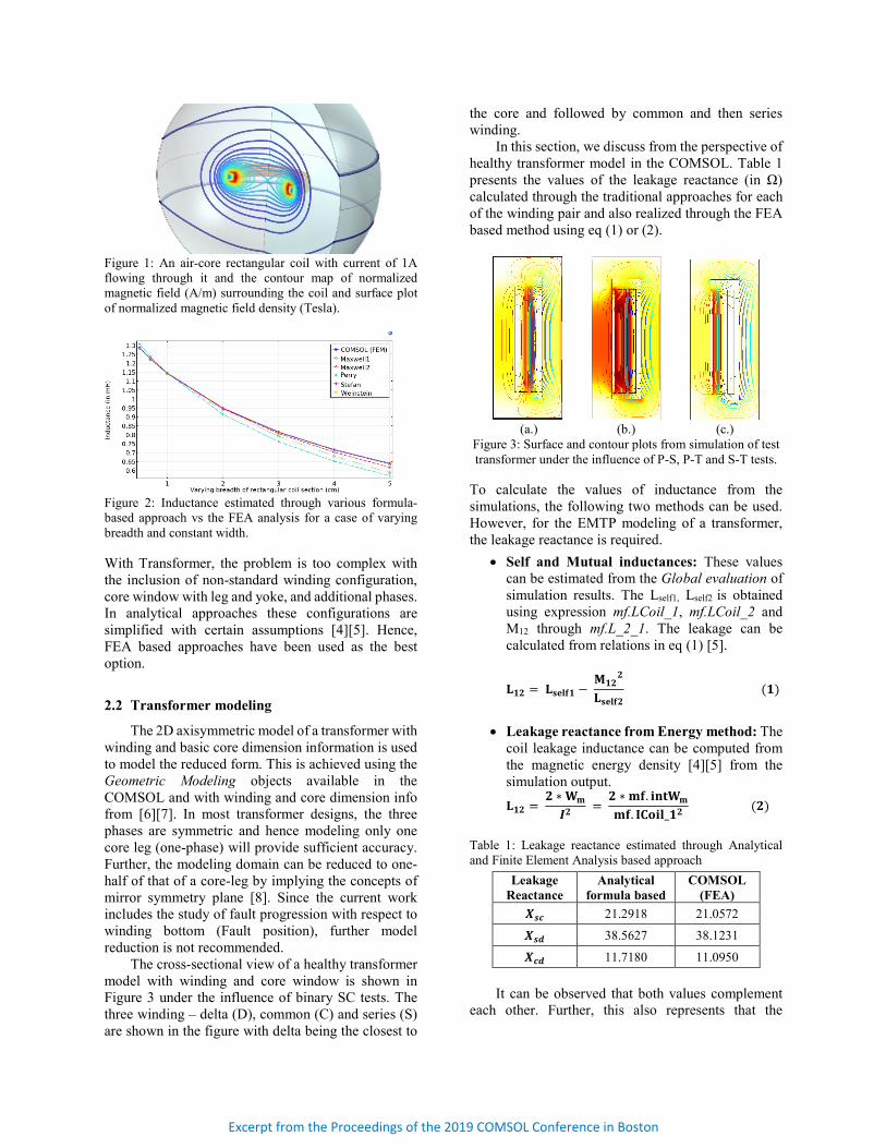
Figure 1: An air-core rectangular coil with current of 1A flowing through it and the contour map of normalized magnetic field (A/m) surrounding the coil and surface plot of normalized magnetic field density (Tesla).
Figure 2: Inductance estimated through various formula-based approach vs the FEA analysis for a case of varying breadth and constant width.
With Transformer, the problem is too complex with the inclusion of non-standard winding configuration, core window with leg and yoke, and additional phases. In analytical approaches these configurations are simplified with certain assumptions [4][5]. Hence, FEA based approaches have been used as the best option.
2.2 Transformer modeling
The 2D axisymmetric model of a transformer with winding and basic core dimension information is used to model the reduced form. This is achieved using the Geometric Modeling objects available in the COMSOL and with winding and core dimension info from [6][7]. In most transformer designs, the three phases are symmetric and hence modeling only one core leg (one-phase) will provide sufficient accuracy. Further, the modeling domain can be reduced to one-half of that of a core-leg by implying the concepts of mirror symmetry plane [8]. Since the current work includes the study of fault progression with respect to winding bottom (Fault position), further model reduction is not recommended.
The cross-sectional view of a healthy transformer model with winding and core window is shown in Figure 3 under the influence of binary SC tests. The three winding – delta (D), common (C) and series (S) are shown in the figure with delta being the closest to
the core and followed by common and then series winding.
In this section, we discuss from the perspective of healthy transformer model in the COMSOL. Table 1 presents the values of the leakage reactance (in Ω) calculated through the traditional approaches for each of the winding pair and also realized through the FEA based method using eq (1) or (2).
(a.)
(b.)
(c.)
Figure 3: Surface and contour plots from simulation of test transformer under the influence of P-S, P-T and S-T tests.
To calculate the values of inductance from the simulations, the following two methods can be used. However, for the EMTP modeling of a transformer, the leakage reactance is required.
• Self and Mutual inductances: These values can be estimated from the Global evaluation of simulation results. The Lself1, Lself2 is obtained using expression mf.LCoil_1, mf.LCoil_2 and M12 through mf.L_2_1. The leakage can be calculated from relations in eq (1) [5].
𝐋𝐋𝟏𝟏𝟏𝟏 = 𝐋𝐋𝐬𝐬𝐬𝐬𝐬𝐬𝐬𝐬𝟏𝟏 − 𝐌𝐌𝟏𝟏𝟏𝟏
𝟏𝟏
𝐋𝐋𝐬𝐬𝐬𝐬𝐬𝐬𝐬𝐬𝟏𝟏 (𝟏𝟏)
• Leakage reactance from Energy method: The
coil leakage inductance can be computed from the magnetic energy density [4][5] from the simulation output.
𝐋𝐋𝟏𝟏𝟏𝟏 = 𝟏𝟏 ∗𝐖𝐖𝐦𝐦
𝑰𝑰𝟏𝟏 = 𝟏𝟏 ∗ 𝐦𝐦𝐬𝐬. 𝐢𝐢𝐢𝐢𝐢𝐢𝐖𝐖𝐦𝐦
𝐦𝐦𝐬𝐬. 𝐈𝐈𝐈𝐈𝐈𝐈𝐢𝐢𝐬𝐬_𝟏𝟏𝟏𝟏 (𝟏𝟏) Table 1: Leakage reactance estimated through Analytical and Finite Element Analysis based approach
Leakage Reactance
Analytical formula based
COMSOL (FEA)
𝑿𝑿𝒔𝒔𝒔𝒔 21.2918 21.0572
𝑿𝑿𝒔𝒔𝒔𝒔 38.5627 38.1231
𝑿𝑿𝒔𝒔𝒔𝒔 11.7180 11.0950 It can be observed that both values complement
each other. Further, this also represents that the
Excerpt from the Proceedings of the 2019 COMSOL Conference in Boston
modeling approximation using the Axisymmetric method characterize the transformer pretty well.
2.3 Inner-winding fault simulations
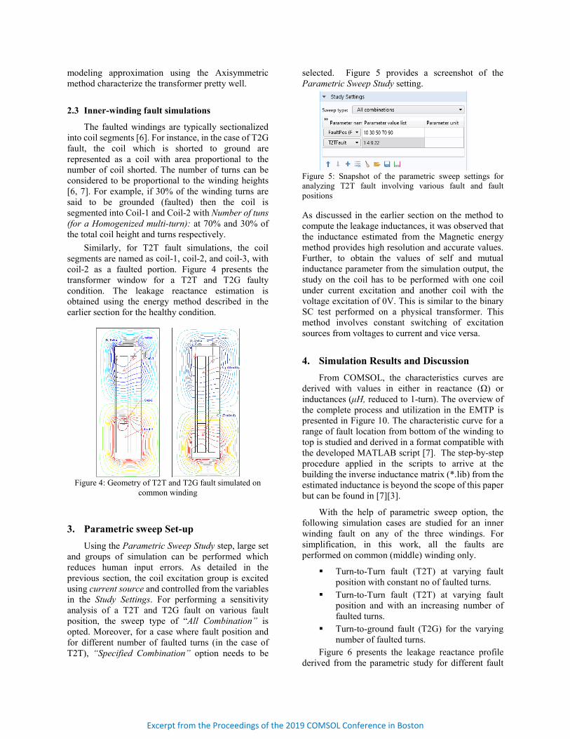
The faulted windings are typically sectionalized into coil segments [6]. For instance, in the case of T2G fault, the coil which is shorted to ground are represented as a coil with area proportional to the number of coil shorted. The number of turns can be considered to be proportional to the winding heights [6, 7]. For example, if 30% of the winding turns are said to be grounded (faulted) then the coil is segmented into Coil-1 and Coil-2 with Number of tuns (for a Homogenized multi-turn): at 70% and 30% of the total coil height and turns respectively.
Similarly, for T2T fault simulations, the coil segments are named as coil-1, coil-2, and coil-3, with coil-2 as a faulted portion. Figure 4 presents the transformer window for a T2T and T2G faulty condition. The leakage reactance estimation is obtained using the energy method described in the earlier section for the healthy condition.
Figure 4: Geometry of T2T and T2G fault simulated on
common winding
3. Parametric sweep Set-up Using the Parametric Sweep Study step, large set
and groups of simulation can be performed which reduces human input errors. As detailed in the previous section, the coil excitation group is excited using current source and controlled from the variables in the Study Settings. For performing a sensitivity analysis of a T2T and T2G fault on various fault position, the sweep type of “All Combination” is opted. Moreover, for a case where fault position and for different number of faulted turns (in the case of T2T), “Specified Combination” option needs to be
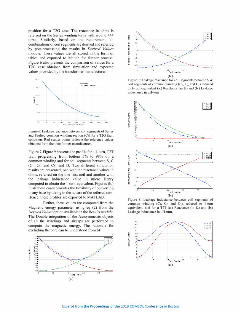
selected. Figure 5 provides a screenshot of the Parametric Sweep Study setting.
Figure 5: Snapshot of the parametric sweep settings for analyzing T2T fault involving various fault and fault positions
As discussed in the earlier section on the method to compute the leakage inductances, it was observed that the inductance estimated from the Magnetic energy method provides high resolution and accurate values. Further, to obtain the values of self and mutual inductance parameter from the simulation output, the study on the coil has to be performed with one coil under current excitation and another coil with the voltage excitation of 0V. This is similar to the binary SC test performed on a physical transformer. This method involves constant switching of excitation sources from voltages to current and vice versa.
4. Simulation Results and Discussion From COMSOL, the characteristics curves are
derived with values in either in reactance (Ω) or inductances (μH, reduced to 1-turn). The overview of the complete process and utilization in the EMTP is presented in Figure 10. The characteristic curve for a range of fault location from bottom of the winding to top is studied and derived in a format compatible with the developed MATLAB script [7]. The step-by-step procedure applied in the scripts to arrive at the building the inverse inductance matrix (*.lib) from the estimated inductance is beyond the scope of this paper but can be found in [7][3].
With the help of parametric sweep option, the following simulation cases are studied for an inner winding fault on any of the three windings. For simplification, in this work, all the faults are performed on common (middle) winding only.
Turn-to-Turn fault (T2T) at varying fault position with constant no of faulted turns.
Turn-to-Turn fault (T2T) at varying fault position and with an increasing number of faulted turns.
Turn-to-ground fault (T2G) for the varying number of faulted turns.
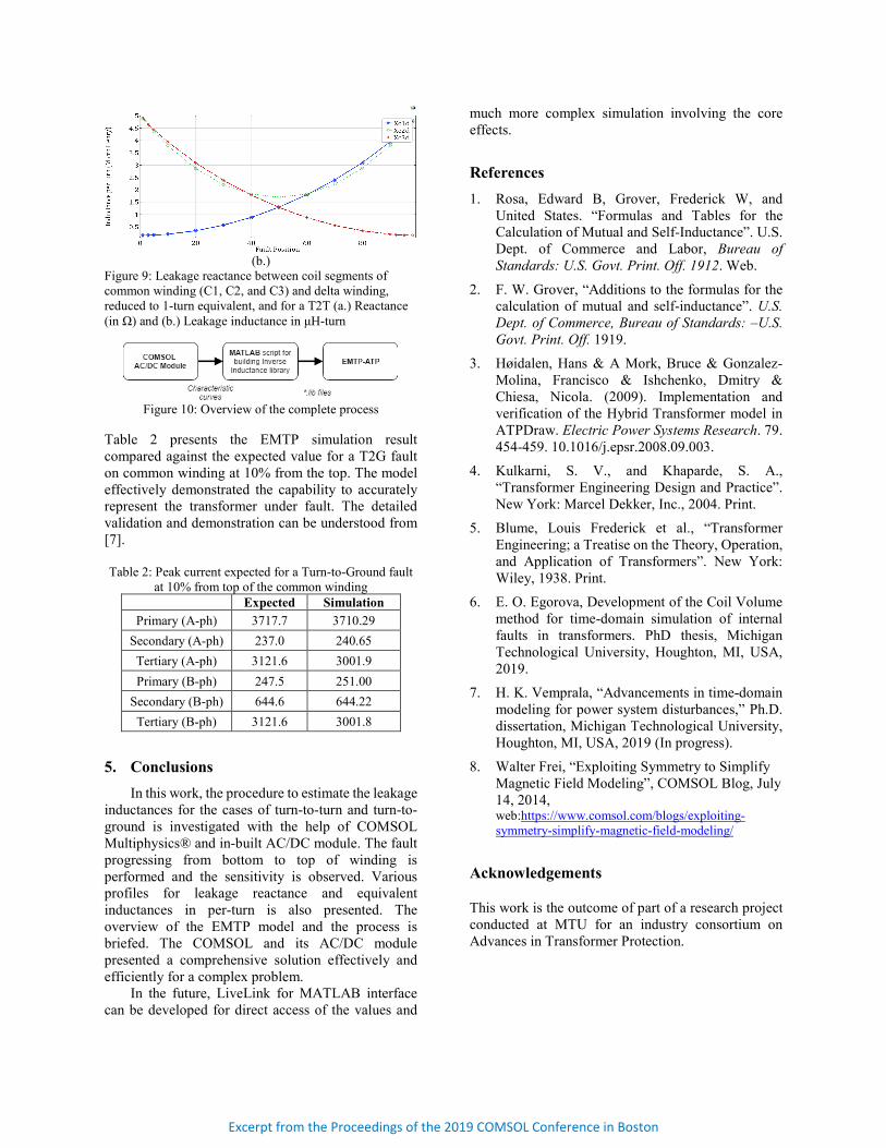
Figure 6 presents the leakage reactance profile derived from the parametric study for different fault
Excerpt from the Proceedings of the 2019 COMSOL Conference in Boston
position for a T2G case. The reactance in ohms is referred on the Series winding turns with around 444 turns. Similarly, based on the requirement, all combinations of coil segments are derived and referred by post-processing the results in Derived Values module. These values are all stored in the form of tables and exported to Matlab for further process. Figure 6 also presents the comparison of values for a T2G case obtained from simulation and expected values provided by the transformer manufacturer.
Figure 6: Leakage reactance between coil segments of Series and Faulted common winding section (C2) for a T2G fault condition. Red scatter points indicate the reference values obtained from the transformer manufacturer.
Figure 7-Figure 9 presents the profile for a 1-turn, T2T fault progressing from bottom 5% to 98% on a common winding and for coil segments between S, C (C1, C2, and C3) and D. Two different simulation results are presented, one with the reactance values in ohms, referred on the one first coil and another with the leakage inductance value in micro Henry computed to obtain the 1-turn equivalent. Figures (b.) in all these cases provides the flexibility of converting to any base by taking in the square of the referred turn. Hence, these profiles are exported to MATLAB.
Further, these values are computed from the Magnetic energy parameter using eq (2) from the Derived Values option available in the Results module. The Double integration of the Axisymmetric objects of all the windings and airgaps are performed to compute the magnetic energy. The rationale for excluding the core can be understood from [4].
(a.)
(b.)
Figure 7: Leakage reactance for coil segments between S & coil segments of common winding (C1, C2, and C3) reduced to 1-turn equivalent (a.) Reactance (in Ω) and (b.) Leakage inductance in μH-turn
(a.)
(b.)
Figure 8: Leakage inductance between coil segments of common winding (C1, C2, and C3), reduced to 1-turn equivalent, and for a T2T (a.) Reactance (in Ω) and (b.) Leakage inductance in μH-turn.
(a.)
Excerpt from the Proceedings of the 2019 COMSOL Conference in Boston
(b.)
Figure 9: Leakage reactance between coil segments of common winding (C1, C2, and C3) and delta winding, reduced to 1-turn equivalent, and for a T2T (a.) Reactance (in Ω) and (b.) Leakage inductance in μH-turn
Figure 10: Overview of the complete process
Table 2 presents the EMTP simulation result compared against the expected value for a T2G fault on common winding at 10% from the top. The model effectively demonstrated the capability to accurately represent the transformer under fault. The detailed validation and demonstration can be understood from [7]. Table 2: Peak current expected for a Turn-to-Ground fault
at 10% from top of the common winding Expected Simulation
Primary (A-ph) 3717.7 3710.29 Secondary (A-ph) 237.0 240.65 Tertiary (A-ph) 3121.6 3001.9 Primary (B-ph) 247.5 251.00
Secondary (B-ph) 644.6 644.22 Tertiary (B-ph) 3121.6 3001.8
5. Conclusions In this work, the procedure to estimate the leakage
inductances for the cases of turn-to-turn and turn-to-ground is investigated with the help of COMSOL Multiphysics® and in-built AC/DC module. The fault progressing from bottom to top of winding is performed and the sensitivity is observed. Various profiles for leakage reactance and equivalent inductances in per-turn is also presented. The overview of the EMTP model and the process is briefed. The COMSOL and its AC/DC module presented a comprehensive solution effectively and efficiently for a complex problem.
In the future, LiveLink for MATLAB interface can be developed for direct access of the values and
much more complex simulation involving the core effects.
References 1. Rosa, Edward B, Grover, Frederick W, and
United States. “Formulas and Tables for the Calculation of Mutual and Self-Inductance”. U.S. Dept. of Commerce and Labor, Bureau of Standards: U.S. Govt. Print. Off. 1912. Web.
2. F. W. Grover, “Additions to the formulas for the calculation of mutual and self-inductance”. U.S. Dept. of Commerce, Bureau of Standards: –U.S. Govt. Print. Off. 1919.
3. Høidalen, Hans & A Mork, Bruce & Gonzalez-Molina, Francisco & Ishchenko, Dmitry & Chiesa, Nicola. (2009). Implementation and verification of the Hybrid Transformer model in ATPDraw. Electric Power Systems Research. 79. 454-459. 10.1016/j.epsr.2008.09.003.
4. Kulkarni, S. V., and Khaparde, S. A., “Transformer Engineering Design and Practice”. New York: Marcel Dekker, Inc., 2004. Print.
5. Blume, Louis Frederick et al., “Transformer Engineering; a Treatise on the Theory, Operation, and Application of Transformers”. New York: Wiley, 1938. Print.
6. E. O. Egorova, Development of the Coil Volume method for time-domain simulation of internal faults in transformers. PhD thesis, Michigan Technological University, Houghton, MI, USA, 2019.
7. H. K. Vemprala, “Advancements in time-domain modeling for power system disturbances,” Ph.D. dissertation, Michigan Technological University, Houghton, MI, USA, 2019 (In progress).
8. Walter Frei, “Exploiting Symmetry to Simplify Magnetic Field Modeling”, COMSOL Blog, July 14, 2014, web:https://www.comsol.com/blogs/exploiting-symmetry-simplify-magnetic-field-modeling/
Acknowledgements
This work is the outcome of part of a research project conducted at MTU for an industry consortium on Advances in Transformer Protection.
Excerpt from the Proceedings of the 2019 COMSOL Conference in Boston