Computation of gaze orientation under unrestrained head movements · Computation of gaze...
12
Journal of Neuroscience Methods 159 (2007) 158–169 Computation of gaze orientation under unrestrained head movements Renaud Ronsse a,∗ , Olivier White b,c , Philippe Lef` evre c,d a Department of Electrical Engineering and Computer Science (Montefiore Institute), Universit´ e de Li` ege, Grande Traverse 10 (B28), B-4000 Li` ege, Belgium b Unit´ e de R´ eadaptation et de m´ edecine physique, Universit´ e catholique de Louvain, Avenue Mounier 53, B-1200 Bruxelles, Belgium c Centre for Systems Engineering and Applied Mechanics (CESAME), Universit´ e catholique de Louvain, Avenue Georges Lemaˆ ıtre 4, B-1348 Louvain-la-Neuve, Belgium d Laboratory of Neurophysiology, Universit´ e catholique de Louvain, Avenue Hippocrate 54, B-1200 Bruxelles, Belgium Received 12 March 2006; received in revised form 7 June 2006; accepted 22 June 2006 Abstract Given the high relevance of visual input to human behavior, it is often important to precisely monitor the spatial orientation of the visual axis. One popular and accurate technique for measuring gaze orientation is based on the dual search coil. This technique does not allow for very large displacements of the subject, however, and is not robust with respect to translations of the head. More recently, less invasive procedures have been developed that record eye movements with camera-based systems attached to a helmet worn by the subject. Computational algorithms have also been developed that can calibrate eye orientation when the head’s position is fixed. Given that camera-based systems measure the eye’s position in its orbit, however, the reconstruction of gaze orientation is not as straightforward when the head is allowed to move. In this paper, we propose a new algorithm and calibration method to compute gaze orientation under unrestrained head conditions. Our method requires only the accurate measurement of orbital eye position (for instance, with a camera-based system), and the position of three points on the head. The calculations are expressed in terms of linear algebra, so can easily be interpreted and related to the geometry of the human body. Our calibration method has been tested experimentally and validated against independent data, proving that is it robust even under large translations, rotations, and torsions of the head. © 2006 Elsevier B.V. All rights reserved. Keywords: Eye–head coordination; Gaze orientation; Gaze measurement; Calibration; Unrestrained head 1. Introduction The accurate measurement of eye movements is crucial to oculomotor research. These movements are commonly expressed in terms of their horizontal, vertical, and torsional components, assuming a ball-in-socket model for the eye with 3 degrees of freedom (DOF). There is an enormous body of litera- ture investigating eye movements under the head fixed condition, and describing accurate methods of measuring these rotations. Such methods are mainly based on either the dual search coil technique (Robinson, 1963; Collewijn et al., 1985) or video image processing devices (e.g., Nakayama, 1974; Haslwanter, 1995; Moore et al., 1996). Both coil- and video-based techniques are widely used by the oculomotor community in behavioral and clinical studies (e.g., Orban de Xivry et al., 2006; Yuksel et al., 2005). ∗ Corresponding author. Tel.: +32 4 366 26 97; fax: +32 4 366 29 89. E-mail address: [email protected] (R. Ronsse). The dual search coil technique is based on the measurement of electric fields induced in a coil placed directly on the sub- ject’s eye. The intensity of the electric field in the coil depends on the orientation of the coil (i.e., of the eye) with respect to an alternating magnetic field. Video image processing devices are designed to measure eye movements with camera-based sys- tems. These techniques are more difficult to apply, however, when gaze orientation arises from a combination of head and eye movements. Video-based systems are usually based on pro- cessing images from a camera fixed to the head. It follows that they do not capture any head movement, but only the eye-in- head component of gaze orientation. The coil technique captures the true eye-in-space orientation, on the other hand, but cannot cope with translations of the head since the magnetic field in the recording chamber is uniform. In addition, rotations of the head always induce a translation of the eye center that is not captured by search coil algorithms. This induces a non-linear bias in the computed signals. In this study, we measure the eye-in-head and head-in-space positions independently. Our technique is therefore valid for 0165-0270/$ – see front matter © 2006 Elsevier B.V. All rights reserved. doi:10.1016/j.jneumeth.2006.06.016
Transcript of Computation of gaze orientation under unrestrained head movements · Computation of gaze...

A
Oddbiameth©
K
1
tecdtaSti1ac2
0d
Journal of Neuroscience Methods 159 (2007) 158–169
Computation of gaze orientation under unrestrained head movements
Renaud Ronsse a,∗, Olivier White b,c, Philippe Lefevre c,d
a Department of Electrical Engineering and Computer Science (Montefiore Institute), Universite de Liege, Grande Traverse 10 (B28), B-4000 Liege, Belgiumb Unite de Readaptation et de medecine physique, Universite catholique de Louvain, Avenue Mounier 53, B-1200 Bruxelles, Belgium
c Centre for Systems Engineering and Applied Mechanics (CESAME), Universite catholique de Louvain,Avenue Georges Lemaıtre 4, B-1348 Louvain-la-Neuve, Belgium
d Laboratory of Neurophysiology, Universite catholique de Louvain, Avenue Hippocrate 54, B-1200 Bruxelles, Belgium
Received 12 March 2006; received in revised form 7 June 2006; accepted 22 June 2006
bstract
Given the high relevance of visual input to human behavior, it is often important to precisely monitor the spatial orientation of the visual axis.ne popular and accurate technique for measuring gaze orientation is based on the dual search coil. This technique does not allow for very largeisplacements of the subject, however, and is not robust with respect to translations of the head. More recently, less invasive procedures have beeneveloped that record eye movements with camera-based systems attached to a helmet worn by the subject. Computational algorithms have alsoeen developed that can calibrate eye orientation when the head’s position is fixed. Given that camera-based systems measure the eye’s positionn its orbit, however, the reconstruction of gaze orientation is not as straightforward when the head is allowed to move. In this paper, we proposenew algorithm and calibration method to compute gaze orientation under unrestrained head conditions. Our method requires only the accurate
easurement of orbital eye position (for instance, with a camera-based system), and the position of three points on the head. The calculations arexpressed in terms of linear algebra, so can easily be interpreted and related to the geometry of the human body. Our calibration method has beenested experimentally and validated against independent data, proving that is it robust even under large translations, rotations, and torsions of theead.
2006 Elsevier B.V. All rights reserved.
ratio
ojoadtwectht
eywords: Eye–head coordination; Gaze orientation; Gaze measurement; Calib
. Introduction
The accurate measurement of eye movements is crucialo oculomotor research. These movements are commonlyxpressed in terms of their horizontal, vertical, and torsionalomponents, assuming a ball-in-socket model for the eye with 3egrees of freedom (DOF). There is an enormous body of litera-ure investigating eye movements under the head fixed condition,nd describing accurate methods of measuring these rotations.uch methods are mainly based on either the dual search coil
echnique (Robinson, 1963; Collewijn et al., 1985) or videomage processing devices (e.g., Nakayama, 1974; Haslwanter,995; Moore et al., 1996). Both coil- and video-based techniques
re widely used by the oculomotor community in behavioral andlinical studies (e.g., Orban de Xivry et al., 2006; Yuksel et al.,005).∗ Corresponding author. Tel.: +32 4 366 26 97; fax: +32 4 366 29 89.E-mail address: [email protected] (R. Ronsse).
crabc
p
165-0270/$ – see front matter © 2006 Elsevier B.V. All rights reserved.oi:10.1016/j.jneumeth.2006.06.016
n; Unrestrained head
The dual search coil technique is based on the measurementf electric fields induced in a coil placed directly on the sub-ect’s eye. The intensity of the electric field in the coil dependsn the orientation of the coil (i.e., of the eye) with respect to anlternating magnetic field. Video image processing devices areesigned to measure eye movements with camera-based sys-ems. These techniques are more difficult to apply, however,hen gaze orientation arises from a combination of head and
ye movements. Video-based systems are usually based on pro-essing images from a camera fixed to the head. It follows thathey do not capture any head movement, but only the eye-in-ead component of gaze orientation. The coil technique captureshe true eye-in-space orientation, on the other hand, but cannotope with translations of the head since the magnetic field in theecording chamber is uniform. In addition, rotations of the headlways induce a translation of the eye center that is not captured
y search coil algorithms. This induces a non-linear bias in theomputed signals.In this study, we measure the eye-in-head and head-in-spaceositions independently. Our technique is therefore valid for

scien
vUtipi
csotahbahserqtiw1prt(eio
asakc
lessrptoso
(
(
d
emttam
2
2
hThmtnac
ctteovaaa
2.1.1. Eye position through image processingAccording to Moore et al. (1996), the vertical and horizontal
Fick angles of eye-in-head orientation as measured by a video-
R. Ronsse et al. / Journal of Neuro
ery large head movements, or even displacements of the body.sing the coil technique with an unrestrained head would require
he measurement of head position, and the integration of thisnformation using an algorithm similar to that presented in thisaper. This study provides a robust geometrical basis for comput-ng the gaze orientation with no restrictions on head movement.
The mathematical developments of this paper are based onommon linear algebra operations. Head rotations are repre-ented as a 3 × 3 matrix, according to the well-known sequencef Fick angles (Fick, 1874; Haslwanter, 1995), and head transla-ions as a 3 × 1 position vector. The combination of head positionnd orientation, hereafter referred to as the head pose, thereforeas 6 DOF. The eye-in-head orientation is similarly representedy a 3 × 3 matrix with 3 DOF, since the center of the eye isssumed to be fixed with respect to the head. Similar formalismsave been used by Allison et al. (1996) in testing the vestibularystem, and by Wang and Sung (2002) to estimate gaze ori-ntation in front of a computer screen. These translations andotations could be represented in other ways, e.g. dual-numberuaternions. There are even some papers dedicated to comparinghese methods, originally from the perspective of robot kinemat-cs (e.g., the survey by Aspragathos and Dimitros, 1998) and laterith respect to the computation of eye rotations (Tweed et al.,990; Haslwanter, 1995). Note that for the sake of simplicity thisaper does not take into account eye-in-head torsion, which cor-esponds to the third Fick angle and captures eye rotation aroundhe optical axis. This angle can be measured by both search coile.g. Tweed et al., 1990) and video-based devices (e.g. Mooret al., 1996), however, and can easily be integrated into the eye-n-head orientation matrix. Eye torsion does not change the linef sight.
This paper also addresses the issue of calibration. We presentn efficient calibration protocol based on gaze fixation duringelf-paced, smooth head movements. This protocol can be easilydapted to a broad range of environments, since it only requiresnowing the location of the fixation target in a 3D, ground-basedoordinate system.
We will particularly stress the algorithmic sequence fol-owed in computing gaze orientation from the head-in-space andye-in-head components, via translations and rotations that areimply described using linear algebra. The method is thereforeimple, robust, and computationally efficient. Its main hardwareequirement is a device that can measure the position of threeoints on the subject’s head in a ground-based coordinate sys-em. This paper also describes experimental results validatingur algorithm, obtained by using a video-based device to mea-ure the eye-in-head position. The method essentially consistsf two steps:
1) determining the eye orientation in the head coordinate sys-tem;
2) rotating the eye orientation vector into a ground-based coor-dinate system, using information on the head orientation
provided by the head measurement device.The rest of this paper is organized as follows. Section 2.1escribes the geometrical relationships required to compute the
FHF
ce Methods 159 (2007) 158–169 159
ye-in-head and head components of gaze, and describes theirutual interaction. Section 2.2 discusses the calibration required
o integrate measurements from both acquisition devices. Sec-ion 2.3 describes the validation tasks. The results of validationre summarized in Section 3, and the characteristics of this newethod are discussed in Section 4.
. Materials and methods
.1. Geometrical developments
A geometric basis for measurement of eye position under theead fixed condition have been derived by Moore et al. (1996).he center of the eye is assumed to be fixed with respect to theead throughout the task. This section explains how Moore’sethod can be extended to unrestrained head conditions, when
he subject’s head is free to move without constraint. This tech-ique provides separate signals for the head and eye orientations,nd therefore distinguishes the relative contributions of eachomponent to gaze orientation.
Gaze is treated as a vector in space, with its origin at the eyeenter and its direction following from both the head’s orienta-ion in space and the eye’s orientation in the head. According tohis method, gaze orientation has to be derived independently forach eye. This paper therefore focuses on derivations involvingne eye, except for a short section dedicated to the calculation ofergence (Section 2.1.4). In the following discussion, matricesre represented by bold uppercase characters (e.g. R), vectorsnd points in 3D space by normal uppercase characters (e.g. P),nd scalar quantities by lowercase italic characters (e.g. x).
ig. 1. Diagram of the eye’s orientation in the head coordinate system [H1, H2,
3]. P denotes the pupil center, and (θeih, φeih) are the horizontal and verticalick angles of the eye’s orientation.

1 scien
b
φ
θ
w(c
at
2
lGmbrptmp
Ftbtdm
to
cid
Hvbe
H
Tf
θ
φ
60 R. Ronsse et al. / Journal of Neuro
ased device are given by
eih = arcsin (−a′21x− a′
22y − a′23) (1)
eih = arcsin
(a′
11x+ a′12y + a′
13
cos (φeih)
), (2)
here the coefficients (‘gains’) a′ij are determined by calibration
see Section 2.2) and (x, y) are the coordinates of the pupil’senter in the camera image. Both angles are depicted in Fig. 1.
The main geometrical developments of Moore et al. (1996)re summarized in Appendix A. The eye orientation vector inhe head coordinate system follows directly from (A.6).
.1.2. Head pose through image processingHead pose is defined in terms of a ground-based (i.e., motion-
ess with respect to the laboratory) coordinate system [G1, G2,3] (see Fig. 2). To efficiently compute the head pose one musteasure the position of three points on the head, which must not
e collinear. Let us denote these points byTa,Tb andTc. They areepresented by grey dots in Figs. 2 and A.1, and define a plane
arallel to the frontal plane H2–H3. Since the head is assumedo be a rigid body, the position of these points completely deter-ines the head pose. It is of particular interest to determine theosition of the eye center, i.e., the origin of the gaze. We assume
ig. 2. Diagram of the whole body. This figure emphasizes the components ofhe gaze orientation: the head component is due to the head pose in the ground-ased coordinate system [G1, G2, G3], and the eye-in-head component is dueo the eye’s orientation in the head coordinate system [H1, H2, H3]. The greyots denote the points Ta, Tb and Tc (see Fig. A.1 for more details), which areeasured to determine the head pose.
w
cmarnGo⎛⎜⎝
Gtv
ψ
2
atsoPt
ce Methods 159 (2007) 158–169
hat the position of this point can be deduced from the positionsf T{a,b,c} and prior knowledge of the head’s anthropomorphic
haracteristics. The position of the eye center, E = (e1, e2, e3)T,s taken as the origin of the [H1, H2, H3] coordinate system asepicted in Fig. 2.
The head orientation is defined as the orientation of the vector1 with respect to the coordinate system [G1, G2, G3]. This unitector is computed using the cross product (hereafter denotedy ×) of two vectors between different pairs of points in T{a,b,c},.g.
1 = (Tc − Ta) × (Tb − Ta)
|(Tc − Ta) × (Tb − Ta)|. (3)
he head orientation angles follow from this vector in a straight-orward manner:
h = arctan
(h12
h11
)(4)
h = −arcsin (h13), (5)
here (h11, h12, h13)T = H1.The torsional component of the head orientation must also be
omputed. This does not influence the line of sight, but it doesodify the relationship between the eye-in-head [H1, H2, H3]
nd ground-based [G1, G2, G3] coordinate systems. The headotation must be computed to know how the two gaze compo-ents should be combined. The head axis H1 is made parallel to1 by left-multiplying the vectors T with the following orthog-
nal rotation matrix:
cos (θh) cos (φh) −sin (θh) cos (θh) sin (φh)
sin (θh) cos (φh) cos (θh) sin (θh) sin (φh)
−sin (φh) 0 cos (φh)
⎞⎟⎠
−1
=
⎛⎜⎝
cos (θh) cos (φh) −sin (θh) cos (θh) sin (φh)
sin (θh) cos (φh) cos (θh) sin (θh) sin (φh)
−sin (φh) 0 cos (φh)
⎞⎟⎠
T
. (6)
eometrically, head torsion corresponds to the angle betweenhis rotated vector (Tc Tb), hereafter referred to as the foreheadector F = (f1, f2, f3)T, and the G2 axis. This angle is equal to
h = arctan
⎛⎜⎜⎜⎝
cos (θh) sin (φh)f1
+sin (θh) sin (φh)f2 + cos (φh)f3
−sin (φh)f1 + cos (θh)f2
⎞⎟⎟⎟⎠ . (7)
.1.3. The gaze in spaceThis section integrates the previously defined eye-in-head
nd head components of the gaze orientation into a single vec-or giving the gaze orientation in the [G1, G2, G3] coordinate
ystem. The origin of this vector is the center of the eye E. Therientation vector follows directly from the eye-in-head vector, and can be obtained by substituting (1) and (2) into (A.6),hen applying three rotations to the result: first by the horizontal

scien
at
P
⎛⎜⎝
1
0
0
s (ψ
s (ψ
)
Pc
2
ddtoekpItp
P
w
s
s
P
2
ttp
(
2
atfibsp
ew1Hoh
R. Ronsse et al. / Journal of Neuro
ngle θh, then by the “meridian” angle φh, and finally by theorsional angle ψh obtained from (4), (5) and (7) respectively:
G =
⎛⎜⎝
cos (θh) −sin (θh) 0
sin (θh) cos (θh) 0
0 0 1
⎞⎟⎠⎛⎜⎝
cos (φh) 0 sin (φh)
0 1 0
−sin (φh) 0 cos (φh)
⎞⎟⎠
=
⎛⎜⎝
cos (θh) cos (φh) cos (θh) sin (φh) sin (ψh) − sin (θh) co
sin (θh) cos (φh) sin (θh) sin (φh) sin (ψh) + cos (θh) co
−sin (φh) cos (φh) sin (ψh)
G therefore denotes the vector from E to P in the ground-basedoordinate system, and defines the orientation of the line of sight.
.1.4. VergenceIn general, the lines of sight of both eyes intersect at a specific
istance from the subject called the depth of focus. The angleefining the difference between the two lines of sight is calledhe vergence. This point of intersection is easily determined withur method, since the origins (El and Er, for the left and rightyes respectively) and directions (PGl and PGr) of both lines arenown. While the two lines of sight should belong to a commonlane, measurement noise may skew their apparent orientations.n this case, the best approximation to their point of intersec-ion is halfway along the segment connecting their two closestoints.1 This point, denoted PGv, is equal to (Goldman, 1990)
Gv =(El + PGlsl + Er + PGrsr)
2, (9)
here sl and sr are given by
l =det (Er − El,PGr,PGl × PGr)
|PGl × PGr|2(10)
r =det (Er − El,PGl,PGl × PGr)
|PGl × PGr|2. (11)
Gv can therefore be interpreted as the subject’s point of interest.
.1.5. Summary of the procedureAfter calibration (see Section 2.2) it is possible to compute
he angular orientation of the eye in space, given the position ofhe pupil center (x, y)T in the head coordinate system and theositions of the points T, as follows:
(i) The head orientation angles θh, φh, and ψh are computed
from the positions of Ta, Tb and Tc using Eqs. (4), (5) and(7).(ii) The position of the eye center E is computed from thepositions of Ta, Tb and Tc and known anthropomorphicparameters.
1 Geometrically, this segment is orthogonal to both lines of sight.
tcdait
i
ce Methods 159 (2007) 158–169 161
0 0
cos (ψh) −sin (ψh)
sin (ψh) cos (ψh)
⎞⎟⎠P
h) cos (θh) sin (φh) cos (ψh) + sin (θh) sin (ψh)
h) sin (θh) sin (φh) cos (ψh) − cos (θh) sin (ψh)
cos (φh) cos (ψh)
⎞⎟⎠P = RhP
(8
(iii) Vertical and horizontal eye angles are computed from (1)and (2), using coefficients determined through calibration.
(iv) The eye-in-head orientation vector P is then determinedfrom these angles and (A.6).
(v) The eye orientation vector is expressed in terms of theground coordinate system by applying the rotation matrix(8).
(vi) Optionally, the eye-in-space horizontal and vertical Fickangles of the gaze are computed by the equations
θG = arctan
(pG2
pG1
)(12)
φG = −arcsin(pG3), (13)
where (pG1, pG2 , pG3)T = PG.vii) The point of intersection between the lines of sight and the
angle of vergence can also be computed, according to theequations derived in Section 2.1.4.
.2. Calibration method
As addressed earlier, the points T fixed to the head aressumed to be measured in the ground-based coordinate sys-em. We also assume that they define a plane parallel to therontal plane, such that θh =φh =ψh = 0 when the subject is look-ng straight ahead (the primary position). If the points T cannote accurately fixed with respect to the subject’s head, they cantill be calibrated to ensure that θh =φh =ψh = 0 in the primaryosition by a method outlined in Appendix B.
Calibration protocols for the measurement of eye-in-head ori-ntation via pupil detection by image processing devices areell documented in the literature (e.g., Haslwanter and Moore,995; Moore et al., 1996; Clarke et al., 2002; Schreiber andaslwanter, 2004). They are generally based on a small numberf fixations at known horizontal and vertical Fick angles in theead coordinate system. The objective of calibration is to iden-ify the unknown coefficients a′
ij in (1) and (2). The torsionalomponent does not need to be calibrated for image processingevices, since the polar cross-correlation technique provides anngular measurement directly. It is only necessary to define an
ral reference signature indicating the eye’s primary position inhe orbit.This paper considers tasks in a framework where the heads unrestrained, and it is inconvenient to ask a subject to keep

1 scien
tttwimppv[
t
θ
φ
w
(
it(or⎛⎜⎝
ccsghhbiv
gtIna
2
upv
hi
(
(
st“ftsr
2
farAtiwC
ttIFatoPiPa
62 R. Ronsse et al. / Journal of Neuro
heir head fixed during calibration. The identification of fixationargets at known horizontal and vertical positions with respecto the head coordinate system is therefore impractical. To copeith these restrictions, we propose a calibration protocol that
ntegrates the head pose measurement. The subject is asked toove their head while keeping their gaze fixed on a specific
oint. The results of the calibration have to match the eye dis-lacements generated by this procedure, given the horizontal andertical Fick angles of the target in the head coordinate systemH1, H2, H3] (Fig. 2).
In the head coordinate system, the Fick angles of the fixationarget C vary with head position as follows:
tar = arctan
(cf2
cf1
)(14)
tar = −arcsin (cf3), (15)
here
cf1, cf2, cf3)T = Cf = RTh (C − E) (16)
s the position of C in the head coordinate system whose origin ishe eye center. The calibration is performed by inverting (1) and2), and adding a third equation that represents the translationffset (see Maxwell, 1951; Denavit and Hartenberg, 1955, foreferences about general homogeneous coordinates):
sin (θtar) cos (φtar)
−sin (φtar)
1
⎞⎟⎠
= A
⎛⎜⎝x
y
1
⎞⎟⎠ =
⎛⎜⎝a′
11 a′12 a′
13
a′21 a′
22 a′23
a′31 a′
32 a′33
⎞⎟⎠⎛⎜⎝x
y
1
⎞⎟⎠ . (17)
The best “gain” matrix A for this overdetermined systeman be determined by any numerical processing software. Theomputation gives the best-fitting solution matrix, in the leastquares sense, to the series of eye signals (x, y, 1)T and tar-et signals (sin (θtar) cos (φtar), −sin (φtar), l)T generated by theead movements. This problem is well-conditioned, since theorizontal and vertical eye positions generated during the cali-ration task are highly independent. The gains a′
31 and a′32 are
dentified to zero, and a′33 to 1, to agree with the form of the
ectors used in (17).The subjects we tested reported no difficulty in maintaining
aze fixation during the calibration task, since the velocity ofheir head displacements was only about 25◦ s−1 on average.n this range the gain of smooth pursuit is very close to 1 withegligible phase lag (see Lisberger et al., 1981), validating theccuracy of gaze fixation for the expected behavior.
.2.1. Summary of the procedure
To calibrate the eye-in-head orientation with a video-basednit, the subject is asked to maintain gaze fixation on a knownoint (C) while moving their head first horizontally and thenertically. A series of pupil center displacements (x, y)T and
csat
ce Methods 159 (2007) 158–169
ead pose movements are thereby generated. The gain matrix As obtained through the following procedure:
(i) If necessary, the points T are artificially corrected suchthat θh =φh =ψh = 0 in the primary position by asking thesubject to maintain this position for a few seconds. Thisprocedure is detailed in Appendix B.
(ii) The head Fick angles θh, φh andψh are calculated from theT positions and Eqs. (4), (5) and (7).
iii) The position of the eye center E is computed from thepositions of Ta, Tb and Tc and known anthropomorphicparameters.
(iv) The target position in the head coordinate system is com-puted from (16).
(v) The Fick angles of the target in the head coordinate systemare computed by (14) and (15).
vi) The components a′ij of (17) are calculated, using θtar and
φtar from the previous step and (x, y)T values from the eye-in-head measurement device.
This calibration method could be easily adapted to clinicaltudies of patients with oculomotor disorders who are not ableo maintain gaze fixation while moving the head. In this case, adiscretized” version of the calibration task could be proposed:or several steady head positions, the patient would be askedo stabilize their gaze towards the calibration target C. Onlyteady eye-head orientations could be used to compute the linearegression (17).
.3. Experimental validation
Data have been collected on five human subjects (S1 isemale, and S2–S5 are male) between 24 and 27 years ofge (mean 25.4). They provided informed written consent, andeported no history of neurological or musculoskeletal disorder.ll had normal vision, either natural or corrected. One subject is
he first author of this paper, while the others were naive regard-ng the goals of the experiment. All the procedures conductedere approved by the Universite catholique de Louvain Ethicsommittee, in compliance with the Helsinki declaration.
A sketch of the experimental setup is given in Fig. 3. Ini-ially, the subject was asked to stand upon a cross, marked onhe ground (point A). He or she had to keep their gaze fixed on anRED marker (point C) placed on a camera tripod 1.3 m away.ollowing the method described in Section 2.2, each subject wassked to move their head first with a pure horizontal movement,hen with a pure vertical movement (Pattern 1 on Fig. 3). Twother patterns were used to validate the calibration so obtained.attern 2 consisted of a circular head motion, and was used to val-
date the coupling between horizontal and vertical components.attern 3 consisted of a ∞-shaped head motion, the subject beingsked to generate significant head torsion. The robustness of the
alibration to lateral displacement was evaluated by asking theubject to repeat these patterns while standing on positions Bnd C (0.5 m to the right and left of point A). The robustness ofhe calibration to distance was evaluated by repeating the proce-
scien
dtoivcotppm
evVtewptt2vwcahalfiaT
FBC∞
tctgeoepCe2
3
Svd
3
tpkttp
R. Ronsse et al. / Journal of Neuro
ure at position D (0.5 m in front of point A). The task was easyo perform under all conditions, resulting in unambiguous gazerientations. Except for pattern 1 on position A, which was usedn calibration, every other pattern and position was used only toalidate the method. The method’s accuracy is determined byomparing the computed gaze orientation to the actual positionf C. The subjects went through the following sequence of pat-erns: position A, pattern 1 (calibration) then patterns 2 and 3;osition B, patterns 1, 2 and 3; position C, patterns 1, 2 and 3;osition D, patterns 1, 2 and 3; finally position A, pattern 1 onceore for a second calibration.Two-dimensional (horizontal and vertical) recordings of both
yes were made simultaneously using a Chronos head-mounted,ideo-based eye tracker (Clarke et al., 2003, CHRONOSISION GmbH, Berlin, Germany). The calculation of eye posi-
ions was based on determination of the pupil center (see Zhut al., 1999, and references therein). The recording frame rateas 200 Hz. The system is linear in the horizontal and verticallanes for deflections up to ±20◦, and has a resolution betterhan 5′. System noise was measured to be 0.11◦ for the horizon-al plane and 0.09◦ for the vertical plane (Clarke et al., 2002,003). A bite-bar was mounted on the helmet frame to pre-ent slippage between the head and the helmet. This bite-baras not mandatory, however, and could be removed for subject
omfort. In this case the calibration task would be performedt regular intervals to compensate for any slippage between theead and the helmet. The second video-based device used was3D position measurement system. The positions of infrared
ight-emitting diodes (IREDs) on the Chronos helmet and at thexation target (the four grey dots on Fig. 3) were measured usingn OptoTrak 3020 system (Northern Digital, Ontario, Canada).he OptoTrak was mounted on the ceiling about 3 m in front of
ig. 3. Experimental setup. Standing on one of the fixed positions (crosses A,, C and D), the subject is asked to maintain gaze fixation on the grey spot (point) while moving their head in a cross pattern (1), a circular pattern (2), or an-shaped pattern (3).
E
f
E
f
poticutla
poascesr
a
ce Methods 159 (2007) 158–169 163
he subject. The positions of the IREDs were rotated so that theyould be expressed in a coordinate system with axes parallel tohe floor and centered on the fixation target. The axes G’s of thisround coordinate system are shown in Fig. 2. The position ofach IRED was sampled with a frequency of 200 Hz and res-lution of about 0.1 mm within this working environment. Theye signals and IRED signals were filtered at 48 Hz by a zero-hased digital filter (autoregressive, forward and backward). Thehronos eye tracker and the OptoTrak were synchronized by anxternal computer. Each pattern was executed over a period of0 s, and its data recorded in a separate file.
. Results
Experimental results are presented in two separate sections.ection 3.1 describes the calibration results, and Section 3.2alidates the calibration matrices using data from the patternsescribed in Section 2.3.
.1. Calibration
Calibration of the eye-in-head measurement device relies onhe algorithm described in Section 2.2. It assumes that the eyeosition E is known perfectly with respect to the points T. Toeep the method as simple as possible, we assume that this dis-ance is similar for all subjects. Empirical observations of allhe subjects wearing the helmet allow us to estimate the eyeositions as
=2BT + Tc
3− 0.09 m H1 + 0.01 m F (18)
or the left eye, and
=2BT + Tb
3− 0.09 m H1 − 0.01 m F (19)
or the right eye. In these equations BT is the barycenter of the
oints T (see Appendix B), which gives an interocular distancef about 0.07 m. Note that any errors induced by this approxima-ion are corrected to the zeroth and first order by the linear gainsn (17) during the calibration procedure. A more complicatedalibration algorithm could treat these distances as additionalnknown parameters to be determined. In this case the calibra-ion would become non-linear, however, and in addition to beingess robust would require a more complicated and computation-lly costly implementation.
To calibrate the helmet unit, the subject executed pattern 1 inosition A (see Fig. 3). From the E position computed by (18)r (19), the target Fick angles are computed according to (14)nd (15). The overall motion is slow enough to assume that theubjects maintained a permanent fixation on the point C. In thealibration data (a 20 s recording) the experimenter manuallyxcluded eye blinks, small saccades, and eye movements out-
ide the detection range to reduce signal distortion in the linearegression (17).The real target angles and eye-in-head angles are comparedfter calibration in Fig. 4 (left eye, S2). This diagram empha-
164 R. Ronsse et al. / Journal of Neuroscience Methods 159 (2007) 158–169
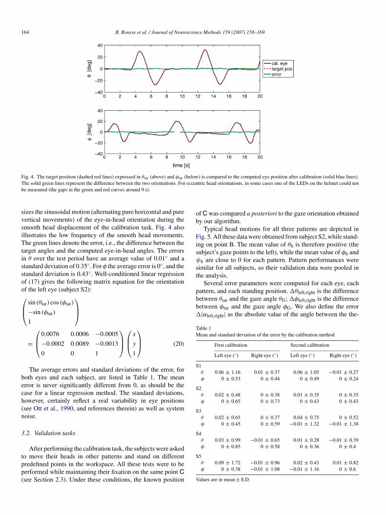
Fig. 4. The target position (dashed red lines) expressed in θtar (above) and φtar (below) is compared to the computed eye position after calibration (solid blue lines).T eccenb
svsiTtissoo⎛⎜⎝
bech(n
3
tpp(
ob
Fisψ
st
pattern, and each standing position. �θleft,right is the differencebetween θtar and the gaze angle θG; �φleft,right is the differencebetween φtar and the gaze angle φG. We also define the error�|αleft,right| as the absolute value of the angle between the the-
Table 1Mean and standard deviation of the error by the calibration method
First calibration Second calibration
Left eye (◦) Right eye (◦) Left eye (◦) Right eye (◦)
S1θ 0.06 ± 1.16 0.01 ± 0.37 0.06 ± 1.05 −0.01 ± 0.27φ 0 ± 0.53 0 ± 0.44 0 ± 0.49 0 ± 0.24
S2θ 0.02 ± 0.48 0 ± 0.38 0.01 ± 0.35 0 ± 0.35φ 0 ± 0.65 0 ± 0.73 0 ± 0.43 0 ± 0.43
S3θ 0.02 ± 0.65 0 ± 0.37 0.04 ± 0.75 0 ± 0.52φ 0 ± 0.45 0 ± 0.59 −0.01 ± 1.32 −0.01 ± 1.38
S4θ 0.03 ± 0.99 −0.01 ± 0.65 0.01 ± 0.28 −0.01 ± 0.39φ 0 ± 0.85 0 ± 0.58 0 ± 0.36 0 ± 0.4
he solid green lines represent the difference between the two orientations. Fore measured (the gaps in the green and red curves around 9 s).
izes the sinusoidal motion (alternating pure horizontal and pureertical movements) of the eye-in-head orientation during themooth head displacement of the calibration task. Fig. 4 alsollustrates the low frequency of the smooth head movements.he green lines denote the error, i.e., the difference between the
arget angles and the computed eye-in-head angles. The errorsn θ over the test period have an average value of 0.01◦ and atandard deviation of 0.35◦. For φ the average error is 0◦, and thetandard deviation is 0.43◦. Well-conditioned linear regressionf (17) gives the following matrix equation for the orientationf the left eye (subject S2):
sin (θtar) cos (φtar)
−sin (φtar)
1
⎞⎟⎠
=
⎛⎜⎝
0.0076 0.0006 −0.0005
−0.0002 0.0089 −0.0013
0 0 1
⎞⎟⎠⎛⎜⎝x
y
1
⎞⎟⎠ (20)
The average errors and standard deviations of the error, foroth eyes and each subject, are listed in Table 1. The meanrror is never significantly different from 0, as should be thease for a linear regression method. The standard deviations,owever, certainly reflect a real variability in eye positionssee Ott et al., 1990, and references therein) as well as systemoise.
.2. Validation tasks
After performing the calibration task, the subjects were asked
o move their heads in other patterns and stand on differentredefined points in the workspace. All these tests were to beerformed while maintaining their fixation on the same point Csee Section 2.3). Under these conditions, the known positionS
V
tric head orientations, in some cases one of the LEDs on the helmet could not
f C was compared a posteriori to the gaze orientation obtainedy our algorithm.
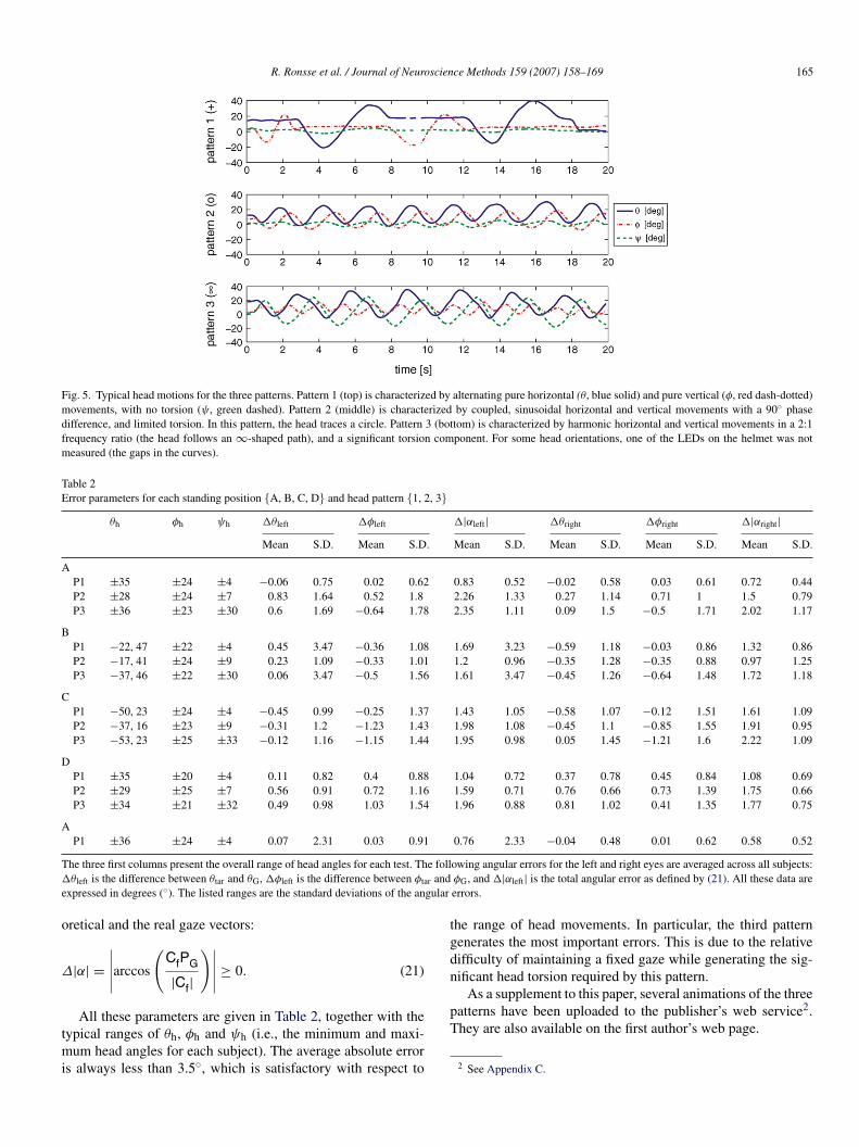
Typical head motions for all three patterns are depicted inig. 5. All these data were obtained from subject S2, while stand-
ng on point B. The mean value of θh is therefore positive (theubject’s gaze points to the left), while the mean value of φh andh are close to 0 for each pattern. Pattern performances were
imilar for all subjects, so their validation data were pooled inhe analysis.
Several error parameters were computed for each eye, each
5θ 0.09 ± 1.72 −0.01 ± 0.96 0.02 ± 0.43 0.01 ± 0.82φ 0 ± 0.38 −0.01 ± 1.08 −0.01 ± 1.16 0 ± 0.6
alues are in mean ± S.D.
R. Ronsse et al. / Journal of Neuroscience Methods 159 (2007) 158–169 165
Fig. 5. Typical head motions for the three patterns. Pattern 1 (top) is characterized by alternating pure horizontal (θ, blue solid) and pure vertical (φ, red dash-dotted)movements, with no torsion (ψ, green dashed). Pattern 2 (middle) is characterized by coupled, sinusoidal horizontal and vertical movements with a 90◦ phasedifference, and limited torsion. In this pattern, the head traces a circle. Pattern 3 (bottom) is characterized by harmonic horizontal and vertical movements in a 2:1frequency ratio (the head follows an ∞-shaped path), and a significant torsion component. For some head orientations, one of the LEDs on the helmet was notmeasured (the gaps in the curves).
Table 2Error parameters for each standing position {A, B, C, D} and head pattern {1, 2, 3}
θh φh ψh �θleft �φleft �|αleft| �θright �φright �|αright|Mean S.D. Mean S.D. Mean S.D. Mean S.D. Mean S.D. Mean S.D.
AP1 ±35 ±24 ±4 −0.06 0.75 0.02 0.62 0.83 0.52 −0.02 0.58 0.03 0.61 0.72 0.44P2 ±28 ±24 ±7 0.83 1.64 0.52 1.8 2.26 1.33 0.27 1.14 0.71 1 1.5 0.79P3 ±36 ±23 ±30 0.6 1.69 −0.64 1.78 2.35 1.11 0.09 1.5 −0.5 1.71 2.02 1.17
BP1 −22, 47 ±22 ±4 0.45 3.47 −0.36 1.08 1.69 3.23 −0.59 1.18 −0.03 0.86 1.32 0.86P2 −17, 41 ±24 ±9 0.23 1.09 −0.33 1.01 1.2 0.96 −0.35 1.28 −0.35 0.88 0.97 1.25P3 −37, 46 ±22 ±30 0.06 3.47 −0.5 1.56 1.61 3.47 −0.45 1.26 −0.64 1.48 1.72 1.18
CP1 −50, 23 ±24 ±4 −0.45 0.99 −0.25 1.37 1.43 1.05 −0.58 1.07 −0.12 1.51 1.61 1.09P2 −37, 16 ±23 ±9 −0.31 1.2 −1.23 1.43 1.98 1.08 −0.45 1.1 −0.85 1.55 1.91 0.95P3 −53, 23 ±25 ±33 −0.12 1.16 −1.15 1.44 1.95 0.98 0.05 1.45 −1.21 1.6 2.22 1.09
DP1 ±35 ±20 ±4 0.11 0.82 0.4 0.88 1.04 0.72 0.37 0.78 0.45 0.84 1.08 0.69P2 ±29 ±25 ±7 0.56 0.91 0.72 1.16 1.59 0.71 0.76 0.66 0.73 1.39 1.75 0.66P3 ±34 ±21 ±32 0.49 0.98 1.03 1.54 1.96 0.88 0.81 1.02 0.41 1.35 1.77 0.75
AP1 ±36 ±24 ±4 0.07 2.31 0.03 0.91 0.76 2.33 −0.04 0.48 0.01 0.62 0.58 0.52
T e foll� r ande gular
o
Δ
tmi
tgdifficulty of maintaining a fixed gaze while generating the sig-nificant head torsion required by this pattern.
As a supplement to this paper, several animations of the three
he three first columns present the overall range of head angles for each test. Thθleft is the difference between θtar and θG, �φleft is the difference between φta
xpressed in degrees (◦). The listed ranges are the standard deviations of the an
retical and the real gaze vectors:
|α| =∣∣∣∣∣arccos
(CfPG
|Cf|
)∣∣∣∣∣ ≥ 0. (21)
All these parameters are given in Table 2, together with theypical ranges of θh, φh and ψh (i.e., the minimum and maxi-
um head angles for each subject). The average absolute errors always less than 3.5◦, which is satisfactory with respect to
pT
owing angular errors for the left and right eyes are averaged across all subjects:φG, and �|αleft| is the total angular error as defined by (21). All these data areerrors.
he range of head movements. In particular, the third patternenerates the most important errors. This is due to the relative
atterns have been uploaded to the publisher’s web service2.hey are also available on the first author’s web page.
2 See Appendix C.

1 scien
4
tttpbc
amIwiweFcmaH
mccaeabcitrWachcprai
etTHe1b1icaeM
tiprmirtocrhnfo
aeosfbmhaTiacElvmto(iamAaVlpTiets
screen, our method allows not only large head movements butalso subject displacements as long as the head markers T remain
66 R. Ronsse et al. / Journal of Neuro
. Discussion
This paper investigates the geometry of human gaze orienta-ions. To compute gaze orientation in a behavioral context wherehe head has complete freedom of movement, not only head rota-ions but also head translations must be taken into account. Thisaper provides a simple calibration protocol that can integrateoth eye-in-head and head-in-space orientations into a singleoordinate system.
Our method rests on separate measurements of the head posend the eye-in-head position. The head pose is determined byeasuring the positions of three markers fixed to the head.
n the present experiment the eye-in-head position is recordedith a video-based device, but any other classical eye record-
ng method (corneal reflection methods, EOG, etc.) will do asell. The availability of independent head and eye-in-head ori-
ntation signals invites further investigation of their interaction.or example, if a search coil is used then eye-in-space angularomponents are recorded directly but a contribution due to headotion must be subtracted from this signal (see, e.g. Crawford
nd Vilis, 1991; Crawford et al., 1999, 2003; Harris et al., 2001;an et al., 2005).Dual search coil and video-based devices are equally popular
ethods of measuring eye orientation, and each has its spe-ific advantages and drawbacks. On the one hand, dual searchoils (Robinson, 1963; Collewijn et al., 1985) are expensivend fragile. They are also invasive, since a human subject canndure the presence of a coil on their eye for at most 40 min,nd require the supervision of an ophthalmologist. Moreover,ecause the coil measures eye orientation in a ground-basedoordinate system it is not straightforward to isolate the eye-n-head component of the gaze orientation. The main advan-ages of the search coil technique are its excellent spatial accu-acy and the high sampling frequencies that can be obtained.
ith horizontal, vertical, and torsional gaze orientations avail-ble in real time, it is easy to implement closed loop proto-ols. On the other hand, recent video image processing devicesave been able to accurately measure eye movements usingamera-based systems (see the paper by Clarke et al., 2003, thatresents the device used in this study). These techniques are cur-ently approaching the search coil technique in terms of spatialnd temporal accuracy. Most importantly, they are much lessnvasive.
With the development of more advanced hardware, a math-matical formalism based on 3D rotations has been establishedo relate facial images to gaze orientation (Nakayama, 1974;weed and Vilis, 1987; Tweed et al., 1990; Van Opstal, 1993;aslwanter, 1995). Horizontal and vertical displacements of the
ye are computed by tracking the pupil center (see Zhu et al.,999, and references therein). Torsion may be computed eithery tracking natural or artificial landmarks on the eye (Nakayama,974; Parker et al., 1985; Ott et al., 1990), or by tracking theral intensity along a circular sampling path (the polar cross-
orrelation method) (Hatamian and Anderson, 1983; Vievillend Masse, 1987; Tweed et al., 1990; Clarke et al., 1991; Mooret al., 1991, 1996; Haslwanter, 1995, 2000; Haslwanter andoore, 1995; Schreiber and Haslwanter, 2004).i
ce Methods 159 (2007) 158–169
The main limitation of video-based acquisition systems ishat they do not capture head motions, since the cameras record-ng eye motion are fixed to a helmet worn by the subject. Thisaper proposes a method of integrating both translations andotations of the head into any video-based system, based on theeasurement of three points on the subject’s head. This extra
nformation allows the gaze orientation to be calculated accu-ately in a ground-based coordinate system. The first part ofhis paper (Section 2.1) covered the geometrical developmentsf our method. Eye-in-head orientation is first computed usinglassical techniques (Moore et al., 1996), then translated andotated into the ground coordinate system once the head poseas been computed. For the sake of simplicity, this paper didot summarize the existing methods of computing eye torsionrom video-based devices. Eye torsion does not modify the linef sight, so is not a critical issue in this paper.
In addition to the accurate video-based devices describedbove, we would like to discuss another fruitful aspect of gazestimation in the literature. Several methods have been devel-ped to estimate the gaze orientation of a head before a computercreen. The goal of such studies is to use gaze as part of the inter-ace between humans and computerized devices, for applicationsoth clinical and otherwise. The main difference between theseethods and the technique described in this paper lies in the
ardware; the cameras that track the eye pupil must be fixed toground-based coordinate system instead of the subject’s head.his has the advantage of measuring gaze orientation directly
n the ground-based coordinate system. On the other hand, itlso requires continuous monitoring of the distance between theamera and the eye, which is not easy to measure accurately.ven though the most recent of these methods take head trans-
ations into account, they cannot compute gaze orientation forery large head displacements (for example, about 1 m). Further-ore, these techniques do not achieve the level of spatial and
emporal resolutions required in oculomotor research. Papersf interest in this field of study include that of Newman et al.2000), which proposes a method of reconstructing the head posen real time (30 Hz) by tracking typical features of the head;nd that of Wang and Sung (2002), which presents a similarethod based on linear algebra with homogeneous coordinates.n overview of this topic can be found in recent papers (Shih
nd Liu, 2004; Yoo and Chung, 2005), as well as the “Computerision Bibliography” web page which refers extensively to this
iterature 3. Finally, an alternative approach to determining theoint of gaze has been developed by Yu and Eizenman (2004).his method is based on the detection of corresponding points
n an image from a head-mounted scene camera and a refer-nce image. This method is not designed to accurately locatehe head and other objects in a 3D ground-based coordinateystem.
In contrast with the restricted workspace of a computer
n the recording space.
3 http://iris.use.edu/Vision-Notes/bibliography/people911.html.

scien
vaito
f
•
•
•
•
•
•
mrpdve
mdpgaeATalttipa(2
pdvr
A
vPtitA
A
neHfeoctc
dsP
P
wmatrix relating the head coordinate system to the camera coor-dinate system. Angular positions of the eye are expressed interms of Fick angles (Fick, 1874; Haslwanter, 1995), which arecommonly used in oculomotor research. If the space around the
R. Ronsse et al. / Journal of Neuro
In Section 2.2, we detailed an algorithm for calibrating aideo-based eye tracker unit by converting pixel outputs intongular displacements. The mathematical operations involvedn this calibration rest on the rotation and translation of vec-ors and matrices, as was the case for computation of the gazerientation.
The main advantages of our method can be summarized asollows:
it is non-invasive for the subjects, since a video-based deviceis used to compute eye-in-head orientation;its algorithm is expressed in terms of linear algebra, and istherefore computationally efficient;it separates the eye-in-head and the head-in-space compo-nents of gaze, thus allowing the study of their mutual interac-tion;it can be used with a wide variety of acquisition devices,provided that the 3D positions of three points on the head canbe independently measured;it is based on the geometry of the body, so is easy to understandand implement;it is robust under challenging experimental conditions;a preliminary version of this method has already beentested in parabolic flight campaigns by the European SpaceAgency.
Future improvements to our method mainly concern algorith-ic issues: nonlinear estimation of the eye center position with
espect to the head markers (this would, however, greatly com-licate the calibration algorithm), more accurate pupil centeretection (see Zhu et al., 1999), decoupling the horizontal andertical axes of eye rotation (Schreiber and Haslwanter, 2004),tc.
Section 3 was devoted to the experimental validation of ourethod. The calibration process has been strongly validated by
ata from five different human subjects, confirming that theroposed linear algorithm accurately reflects the dynamics ofaze orientation. Using the calibration matrices so obtained, welso performed other validation tasks. As expected, the small-st angular errors were measured for the first pattern in position; i.e., for the data using in computing the calibration matrix.he errors remained within reasonable bounds, however, forll head patterns and standing positions. In general, the angu-ar errors obtained in the validation tasks compared favorablyo the natural variability of gaze orientation in typical fixationasks (see Ott et al., 1990, and references therein). The errorsncurred by this method are also similar to those obtained byrevious experiments comparing the accuracy of video-basednd search coil eye tracking techniques in human experimentse.g., Ott et al., 1990; Moore et al., 1996; Clarke et al., 2002,003).
This paper therefore provides a computationally efficientrocedure for computing eye orientation in a ground-based coor-inate system. This method can be implemented rapidly in aariety of settings, since it is based on linear transformationselated to the actual body configuration.
FfiTa
ce Methods 159 (2007) 158–169 167
cknowledgements
This work was supported by the Belgian Program on Interuni-ersity Attraction Poles, initiated by the Belgian Federal Scienceolicy Office; the ‘Fonds National de la Recherche Scientifique’;
he ‘Fondation pour la Recherche Scientifique Medicale’; annternal research grant (‘Fonds Speciaux de Recherche’) fromhe ‘Universite catholique de Louvain’; the European Spacegency; and PRODEX (Belgium).
ppendix A. Eye-in-head orientation
We define an orthogonal, right-handed, head-based coordi-ate system [H1, H2, H3] with its origin at the center of theyeball. The H2 axis is parallel to the interaural axis, and the2 H3 plane is parallel to the frontal plane. The H1 axis there-
ore points out of the face from the occiput (see Fig. A.1). Theye’s primary position is defined as the position where its linef sight corresponds to the H1 axis. We also define a cameraoordinate system [C1, C2, C3], where C2 and C3 lie withinhe image plane and C1 corresponds to the optical axis of theamera.
According to the definition of Moore et al. (1996), the coor-inates of the pupil center with respect to the head coordinateystem P = (p1, p2, p3)T and the the camera coordinate system′ = (p′
1, p′2, p
′3)T are related by
′ = RcamP + Tcam, (A.1)
here Tcam and Rcam are the translation vector and rotation
ig. A.1. Diagram of the head in space. The coordinate system [H1, H2, H3] isxed to the head, with its origin at the center of the (arbitrarily chosen) left eye.his point is also the origin of the gaze orientation vector. The points T{a,b,c}re fixed on the head, and discussed in Section 2.1.2.

1 scien
etfvtef
vcota
P
wiclMp
P
waaec
p
p
waabd
(tp
P
i
φ
θ
T
A
T(tsTcybTf
toe
c
(sv
a
F(av
To
R
T
(
bs
(
68 R. Ronsse et al. / Journal of Neuro
ye is viewed as a sphere marked with parallels and meridians,hen the sequence of Fick angles defining an orientation is asollows: first a horizontal rotation θ along the equator, then aertical rotation φ along a meridian, and finally a torsional rota-ion ψ about the optical axis. According to the right-hand rule,ye movements to the left, down, and clockwise are positiverom the subject’s point of view.
Moore et al. (1996) showed that the horizontal (θcam) andertical (φcam) components of the offset matrix Rcam can beaptured by calibration gains and do not influence the accuracyf measurement if they remain bounded within 5◦. This assump-ion is reasonable, provided the camera is properly fixed to thecquiring device. Eq. (A.1) therefore reduces to
′ =
⎛⎜⎝
1 0 0
0 cos (ψcam) −sin (ψcam)
0 sin (ψcam) cos (ψcam)
⎞⎟⎠P + Tcam, (A.2)
here ψcam denotes an offset rotation of the camera aroundts optical axis. If the distance between the lens plane and theenter of the eye is large compared to the distance between theens plane and the image plane of the camera (Nakayama, 1974;
oore et al., 1996), then the projection P′′ of P′ onto the imagelane is given by
′ =
⎛⎜⎝
0
x
y
⎞⎟⎠ = k
⎛⎜⎝
0
p′2
p′3
⎞⎟⎠ (A.3)
here k is a scaling factor related to the image magnificationnd p′
i are the individual components of P′. By inverting (A.2)nd (A.3), we find the following relation between the actualye position P and the pupil center (x, y)T as measured by theamera:
2 = a11x+ a12y + a13 (A.4)
3 = a21x+ a22y + a23, (A.5)
here the coefficients a11 = a22 = cos(ψcam)/k,12 = −a21 = sin(ψcam)/k, a13 = −cos (ψcam)t2 − sin(ψcam)t3,nd a23 = sin(ψcam)t2 − cos(ψcam)t3 all have to be determinedy an appropriate calibration. The scalar variables pi (ti, etc.)enote the individual components of P (Tcam, etc.) respectively.
The pupil center P follows from applying the Fick rotationθeih, φeih) to the eye’s primary position (rp,0,0)T, where rp ishe distance between the center of the eye and the center of theupil.
=
⎛⎜⎝
cos (θeih) cos (φeih) −sin (θeih) cos (θeih) sin (φeih)
sin (θeih) cos (φeih) cos (θeih) sin (θeih) sin (φeih)
−sin (φeih) 0 cos (φeih)
⎞⎟⎠
⎛ ⎞
⎜⎝rp0
0
⎟⎠ (A.6)
fz
ce Methods 159 (2007) 158–169
These rotations are depicted in Fig. 1. Substituting this resultnto (A.4) and (A.5), we arrive at the eye-in-head orientation:
eih = arcsin
(−a21x+ a22y + a23
rp
)(A.7)
eih = arcsin
(a11x+ a12y + a13
rp cos (φeih)
)(A.8)
his result gives (1) and (2), which define a′ij � aij/rp.
ppendix B. Calibration of the points T
Our gaze estimation method rests on the fact that the points
{a,b,c} define a plane parallel to the frontal plane H2 H3
Fig. A.1), while the forehead vector F = (Tb Tc) is parallelo H2. In theory this ensures that θh =φh =ψh = 0 whenever theubject stands up and looks straight ahead (the primary position).he placement of these points on the subject’s head, however,annot be accurate enough to validate this assumption. Offsetaw (θoff), pitch (φoff); and torsion (ψoff) angles must thereforee measured while a subject is maintaining the primary position.his appendix describes a calibration protocol that compensates
or these errors by virtually moving the points T.Prior to the calibration pattern, the subject is asked to maintain
he primary position by looking straight ahead while their headrientation angles, i.e. the offset angles, are recorded. In this ref-rence posture, the real points T{a,b,c} are related to the so-called
orrected pointsT′{a,b,c} by the transformation (Ta,Tb,Tc) = Roff
T′a,T
′b,T
′c), where Roff is a rotation matrix with exactly the
ame structure as Rh in (8). However, this last relation is onlyalid when the Fick angles of T
′{a,b,c} are equal to zero. To put it
nother way, when the pointsT{a,b,c} are such that their measured
ick angles are equal to zero, we have (T′a,T
′b,T
′c) = R−off
Ta, Tb, Tc). In this case, R−off is the Fick rotation matrix withngles −θoff, −φoff and −ψoff. In order to make this relationalid for any head orientation, the sets of points T{a,b,c} and′{a,b,c} must be pre-multiplied by R
−1h = R
Th (Rh is an orthog-
nal rotation matrix):
Th (T
′a,T
′b,T
′c) = R−offR
Th (Ta,Tb,Tc). (B.1)
he new set of head points is therefore
T′a,T
′b,T
′c) = RhR−offR
Th (Ta,Tb,Tc). (B.2)
Finally, for convenience this rotation is applied around thearycenter BT of T{a,b,c}, ((Ta +Tb +Tc)/3) which is then con-erved.
T′a,T
′b,T
′c) = RhR−offR
Th (Ta − BT,Tb − BT,Tc − BT)
+ (BT,BT,BT) (B.3)
In summary, the set of points T′{a,b,c} can be simply derived
rom the measured points T{a,b,c}. Their Fick angles are equal toero when the subject is in the primary position; the plane they

scien
dtutu
A
i
R
A
A
C
C
C
C
C
C
C
D
F
G
H
H
H
H
H
H
L
M
M
M
N
N
O
O
P
R
S
S
T
T
V
V
W
Y
Y
R. Ronsse et al. / Journal of Neuro
efine is parallel to H2 H3, and the forehead vector F is parallelo H2. The real Fick angles for other head poses are computedsing these corrected points, according to (4), (5) and (7). Forhe sake of simplicity, however, the notation (′) specifying these of corrected points is not used elsewhere in this paper.
ppendix C. Supplementary data
Supplementary data associated with this article can be found,n the online version, at doi:10.1016/j.jneumeth.2006.06.016.
eferences
llison RS, Eizenman M, Cheung BSK. Combined head and eye tracking sys-tem for dynamic testing of the vestibular system. IEEE Trans Biomed Eng1996;43(11):1073–82.
spragathos NA, Dimitros JK. A comparative study of three methods forrobot kinematics. IEEE Trans Syst Man Cybern B Cybern 1998;28(2):135–45.
larke AH, Ditterich J, Druen K, Schonfeld U, Steineke C. Using high framerate cmos sensors for three-dimensional eye tracking. Behav Res MethodsInstrum Comput 2002;34(4):549–60.
larke, AH, Ditterich, J, Druen, K, Schonfeld, U, Steineke, C. The chronos eyetracker: description and verification study; 2003.
larke AH, Teiwes W, Schrerer H. Videooculography—an alternative methodfor measurement of three-dimensional eye movements. In: Schmid R, Zam-barbieri D, editors. Oculomotor control and cognitive processes. Amsterdam:Elsevier; 1991. p. 431–43.
ollewijn H, Van der Steen J, Ferman L, Jansen TC. Human ocular counterroll:assessment of static and dynamic properties from electromagnetic scleralcoil recordings. Exp Brain Res 1985;59(1):185–96.
rawford JD, Ceylan MZ, Klier EM, Guitton D. Three-dimensional eye-head coordination during gaze saccades in the primate. J Neurophysiol1999;81(4):1760–82.
rawford JD, Martinez-Trujillo J, Klier EM. Neural control of three-dimensionaleye and head movements. Curr Opin Neurobiol 2003;13(6):655–62.
rawford JD, Vilis T. Axes of eye rotation and listing’s law during rotations ofthe head. J Neurophysiol 1991;65(3):407–23.
enavit J, Hartenberg RS. A kinematic notation for the lower-pair mechanismbased on matrices. ASME J Appl Mech 1955:215–21.
ick A. Die bewegungen des menschlichen augapfels. Zeitschrift fur rationelleMedizin 1874;4:109–28.
oldman R. Intersection of two lines in three-space. In: Glassner AS, edi-tor. Graphics Gems, vol. I. San Diego: San Diego Academic Press; 1990.p. 304.
an YH, Kumar AN, Reschke MF, Somers JT, Dell’Osso LF, Leigh RJ.Vestibular and non-vestibular contributions to eye movements that com-pensate for head rotations during viewing of near targets. Exp Brain Res2005;165(3):294–304.
arris L, Beykirch K, Fetter M. The visual consequences of deviations in theorientation of the axis of rotation of the human vestibulo-ocular reflex. Vision
Res 2001;41(25–26):3271–81.aslwanter T. Mathematics of three-dimensional eye rotations. Vision Res1995;35(12):1727–39.
aslwanter, T. Computational and experimental aspects of rotatory eye move-ments in three dimensions. Habilitationsschrift; 2000.
Y
Z
ce Methods 159 (2007) 158–169 169
aslwanter T, Moore ST. A theoretical analysis of three-dimensional eye posi-tion measurement using polar cross-correlation. IEEE Trans Biomed Eng1995;42(11):1053–61.
atamian M, Anderson DJ. Design considerations for a real-time ocular coun-terroll instrument. IEEE Trans Biomed Eng 1983;30(5):278–88.
isberger SG, Evinger C, Johanson GW, Fuchs AF. Relationship between eyeacceleration and retinal image velocity during foveal smooth pursuit in manand monkey. J Neurophysiol 1981;46(2):229–49.
axwell EA. General homogeneous coordinates in space of three dimensions.Cambridge, UK: Cambridge University Press; 1951.
oore ST, Curthoys IS, McCoy SG. Vtm-an image-processing systemfor measuring ocular torsion. Comput Methods Programs Biomed1991;35(3):219–30.
oore ST, Haslwanter T, Curthoys IS, Smith ST. A geometric basis for mea-surement of three-dimensional eye position using image processing. VisionRes 1996;36(3):445–59.
akayama K. Photographic determination of the rotational state of the eye usingmatrices. Am J Optom Physiol Opt 1974;51(10):736–42.
ewman R, Matsumoto Y, Rougeaux S, Zelinsky A. Real-time stereo track-ing for head pose and gaze estimation. In: Crowley JL, editor. 4thIEEE international conference on automatic face and gesture recognition;2000.
rban de Xivry JJ, Bennett SJ, Lefevre P, Barnes GR. Evidence for synergybetween saccades and smooth pursuit during transient target disappearance.J Neurophysiol 2006;95(1):418–27.
tt D, Gehle F, Eckmiller R. Video-oculographic measurement of 3-dimensionaleye rotations. J Neurosci Methods 1990;35(3):229–34.
arker JA, Kenyon RV, Young LR. Measurement of torsion from multitemporalimages of the eye using digital signal processing techniques. IEEE TransBiomed Eng 1985;32(1):28–36.
obinson DA. A method of measuring eye movement using a scleral search coilin a magnetic field. IEEE Trans Biomed Eng 1963;10:137–45.
chreiber K, Haslwanter T. Improving calibration of 3-d video oculographysystems. IEEE Trans Biomed Eng 2004;51(4):676–9.
hih SW, Liu J. A novel approach to 3-d gaze tracking using stereo cameras.IEEE Trans Syst Man Cybern B Cybern 2004;34(1):234–45.
weed D, Cadera W, Vilis T. Computing three-dimensional eye posi-tion quaternions and eye velocity from search coil signals. Vision Res1990;30(1):97–110.
weed D, Vilis T. Implications of rotational kinematics for the oculomotor sys-tem in three dimensions. J Neurophysiol 1987;58(4):832–49.
an Opstal J. Representation of eye position in three dimensions. In: Berthoz A,editor. Multisensory control of movement. Oxford: Oxford University Press;1993. p. 27–41.
ieville T, Masse D. Ocular counter-rolling during active head tilting in humans.Acta Otolaryngol 1987;103(3–4):280–90.
ang JG, Sung E. Study on eye gaze estimation. IEEE Trans Syst Man CybernB Cybern 2002;32(3):332–50.
oo DH, Chung MJ. A novel non-intrusive eye gaze estimation usingcross-ratio under large head motion. Comput Vision Image Understand2005;98(1):25–51.
u LH, Eizenman M. A new methodology for determining point-of-gaze in head-mounted eye tracking systems. IEEE Trans Biomed Eng2004;51(10):1765–73.
uksel D, Optican LM, Lefevre P. Properties of saccades in duane retractionsyndrome. Invest Ophthalmol Vis Sci 2005;46(9):3144–51.
hu D, Moore ST, Raphan T. Robust pupil center detection using a cur-vature algorithm. Comput Methods Programs Biomed 1999;59(3):145–57.