COMPLETE MV-BPL COMMUNICATIONS SOLUTION FOR LARGE …
5
24 th International Conference on Electricity Distribution Glasgow, 12-15 June 2017 Paper 0933 CIRED 2017 1/5 COMPLETE MV-BPL COMMUNICATIONS SOLUTION FOR LARGE AMI AND GRID AUTOMATION DEPLOYMENTS Jon AGUIRRE VALPARIS Aitor AMEZUA Juan Antonio SANCHEZ Ormazabal - Spain Ormazabal - Spain Ormazabal - Spain [email protected] [email protected] [email protected] Alberto SENDIN Javier SIMON Stephen DOMINIAK Iberdrola – Spain Iberdrola – Spain HSLU - Switzerland [email protected] [email protected] [email protected] ABSTRACT This paper presents a comprehensive solution for broadband backbone communications systems over the medium voltage power lines (MV-BPL) for large AMI and grid automation deployments. Roll out experience, materials, monitoring and control systems will be outlined together with the on-going research activities. INTRODUCTION All over the world, regulators are pushing for improved power quality and supply continuity (SAIDI, SAIFI) and the implementation of energy efficiency measures. The electricity distribution network is undergoing a deep transformation towards its digitalisation, where secondary transformer substations are affected by many of these innovations. Today, medium voltage grid is responsible for almost 85% of supply continuity problems suffered by end customers [1]. Therefore, investments in medium voltage grid automation equipment are defined as strategical to help improving power quality and supply continuity. The use of accurate medium voltage measurements (V, I, P, Q, E) has allowed to improve grid state estimation together with the reliability of fault detector indicators enabling control systems ready for automatic grid recovery [2]. These functionalities have increased dramatically the number of data collected per installation, demanding more and better communication services to Remote Terminal Units. Contrary to the medium voltage equipment, where the evolution of the systems has been progressive, in the low voltage side the irruption of SmartMeters has produced a disruptive change in the design and implementation of new infrastructures related to measurement and billing of energy consumers, so called Advanced Metering Infrastructure or AMI. These changes have influenced deeply the communication technologies and especially those that provide the capillarity the electricity network demands. Backbone connection from the consumers to the head end systems [3] is critical to support all the services. Many technologies are available in the market and not a single one does comply with all technical and economical requirements. Best solution is the combination of a variety of technologies (MV-BPL, 2G/3G/4G mobile, fibre optics, digital radio…) which enable the larger number of services and cover practically all the distribution network with a proper balance between private and commercial solutions. Two key aspects must be borne in mind when selecting the communications technology to be deployed: - Ensure proper operation: the applications demand many services (IP communications, cybersecurity protocols, support distribution protocols, communication network management services, devices’ firmware upgrades…) and large amount data (meter readings data for millions of clients, monitoring data for tens of thousands of substations…) to be exchanged between the head end systems and the devices in the field, with high reliability and availability standards. - Seamless deployment: network planning, system engineering, procurement, installation, commissioning operation and maintenance must be as simple as possible to keep overhead cost, CAPEX and OPEX low. Compared to other mature technologies Medium Voltage Broadband PowerLine communications (MV-BPL) is a technology which has been developed to provide broadband and low latency IP connectivity between transformer substations by means of the MV cables and lines [4]. For the deployment to be successful, it is important to observe a minimum set of rules that will be defined in the paper. The materials needed for a complete working solution will also be described, from the BPL modem to the MV couplers to inject the signal in GIS and AIS substations. The need of a Network Management System (NMS) to monitor, control, operate and maintain large quantity of devices will also be pointed out, along with troubleshooting of real cases and good practice guidelines. The result of the proposed system is a private network that is fully owned and operated by the DSO/DNO. At present, the system is being rolled out and successfully operating in 10,000+ transformer substations in 24kV and 36kV underground networks. Finally, on-going research activities will be presented. With the aim of being able to deploy the technology in any medium voltage grid, scenarios containing overhead lines are being evaluated. A successful proof of concept project has been completed and first pilot installations will be installed in locations where a favourable regulation exists.
Transcript of COMPLETE MV-BPL COMMUNICATIONS SOLUTION FOR LARGE …

24th International Conference on Electricity Distribution Glasgow, 12-15 June 2017
Paper 0933
CIRED 2017 1/5
COMPLETE MV-BPL COMMUNICATIONS SOLUTION FOR LARGE AMI AND GRID
AUTOMATION DEPLOYMENTS
Jon AGUIRRE VALPARIS Aitor AMEZUA Juan Antonio SANCHEZ
Ormazabal - Spain Ormazabal - Spain Ormazabal - Spain
[email protected] [email protected] [email protected]
Alberto SENDIN Javier SIMON Stephen DOMINIAK
Iberdrola – Spain Iberdrola – Spain HSLU - Switzerland
[email protected] [email protected] [email protected]
ABSTRACT
This paper presents a comprehensive solution for
broadband backbone communications systems over the
medium voltage power lines (MV-BPL) for large AMI
and grid automation deployments. Roll out experience,
materials, monitoring and control systems will be
outlined together with the on-going research activities.
INTRODUCTION
All over the world, regulators are pushing for improved power quality and supply continuity (SAIDI, SAIFI) and the implementation of energy efficiency measures. The electricity distribution network is undergoing a deep transformation towards its digitalisation, where secondary transformer substations are affected by many of these innovations.
Today, medium voltage grid is responsible for almost 85% of supply continuity problems suffered by end customers [1]. Therefore, investments in medium voltage grid automation equipment are defined as strategical to help improving power quality and supply continuity. The use of accurate medium voltage measurements (V, I, P, Q, E) has allowed to improve grid state estimation together with the reliability of fault detector indicators enabling control systems ready for automatic grid recovery [2]. These functionalities have increased dramatically the number of data collected per installation, demanding more and better communication services to Remote Terminal Units.
Contrary to the medium voltage equipment, where the evolution of the systems has been progressive, in the low voltage side the irruption of SmartMeters has produced a disruptive change in the design and implementation of new infrastructures related to measurement and billing of energy consumers, so called Advanced Metering Infrastructure or AMI. These changes have influenced deeply the communication technologies and especially those that provide the capillarity the electricity network demands. Backbone connection from the consumers to the head end systems [3] is critical to support all the services.
Many technologies are available in the market and not a single one does comply with all technical and economical requirements. Best solution is the combination of a variety of technologies (MV-BPL, 2G/3G/4G mobile,
fibre optics, digital radio…) which enable the larger number of services and cover practically all the distribution network with a proper balance between private and commercial solutions.
Two key aspects must be borne in mind when selecting the communications technology to be deployed:
- Ensure proper operation: the applications demand many services (IP communications, cybersecurity protocols, support distribution protocols, communication network management services, devices’ firmware upgrades…) and large amount data (meter readings data for millions of clients, monitoring data for tens of thousands of substations…) to be exchanged between the head end systems and the devices in the field, with high reliability and availability standards. - Seamless deployment: network planning, system engineering, procurement, installation, commissioning operation and maintenance must be as simple as possible to keep overhead cost, CAPEX and OPEX low.
Compared to other mature technologies Medium Voltage Broadband PowerLine communications (MV-BPL) is a technology which has been developed to provide broadband and low latency IP connectivity between transformer substations by means of the MV cables and lines [4].
For the deployment to be successful, it is important to observe a minimum set of rules that will be defined in the paper. The materials needed for a complete working solution will also be described, from the BPL modem to the MV couplers to inject the signal in GIS and AIS substations. The need of a Network Management System (NMS) to monitor, control, operate and maintain large quantity of devices will also be pointed out, along with troubleshooting of real cases and good practice guidelines.
The result of the proposed system is a private network that is fully owned and operated by the DSO/DNO. At present, the system is being rolled out and successfully operating in 10,000+ transformer substations in 24kV and 36kV underground networks.
Finally, on-going research activities will be presented. With the aim of being able to deploy the technology in any medium voltage grid, scenarios containing overhead lines are being evaluated. A successful proof of concept project has been completed and first pilot installations will be installed in locations where a favourable regulation exists.

24th International Conference on Electricity Distribution Glasgow, 12-15 June 2017
Paper 0933
CIRED 2017 2/5
MV-BPL TECHNOLOGY
This broadband communication solution, offers the
possibility to extend an access point (or more than one for
high availability features [5]) to a number of secondary
transformer substations through PLC technology over the
Medium Voltage network.
Figure 1: MV-BPL cluster example
For this purpose, PLC communication equipment shall be
installed in various neighbouring secondary substations.
The group of installations will result in an IP based
communication network where an access point should be
provided (2G/3G/4G, Fiber Optics, xDSL …) to connect
the created Local Area Network or cluster to the
backbone communications network.
Architecture and deployment rules
With more than 10.000 MV-BPL communication devices
deployed, the following architecture and conservative
deployment rules are defined to ensure a successful
communication service in large deployments, avoiding
previous onsite assessment.
The architecture of the medium voltage installations
connected can support daisy chained or star topologies,
but it is not recommended to install clusters with more
than 15 nodes in a row or 20 in total.
The cluster is managed by a device defined as Master,
being the rest of the devices named Repeaters. The
backbone or access point could be installed in any of the
nodes, but it is recommended to place it in the the Master.
Technically, the technology allows to use a bandwidth
from 2 to 34MHz with a bit rate of 200 Mbps. Experience
has shown that as Medium Voltage cables were not
conceived as a communication channel, the attenuation of
the cables does not allow the use of high frequencies for
reasonable cable lengths, i.e. communication distances.
During the development of PLC products for Medium
Voltage networks, intensive field tests were performed to
achieve the deployment rules for massive roll-outs
(conservative enough to guarantee the operation) and
search the limits of the technology. Reaching to an
optimal point where 2 frequency bands are used: 2-7MHz
and 8-18MHz.
To understand this conclusion, it has to be taken into
account that the higher the frequency, the greater the
attenuation in the cable. On the contrary, the lower the
frequency the more complicated is to guarantee the
proper coupling of the signal to the medium voltage as a
bigger capacitive coupler is required to obtain lower
insertion losses for low frequencies. These constraints
and the necessity to have more than one frequency mode
of operation to allow the installation of adjacent clusters,
results in the selected 2 frequency modes of operation.
In addition to frequency band or cable distances, cable
types also need to be taken into consideration. The
following table summarizes the deployment conditions:
MODE: 2-7MHz MODE: 8-18MHz
Lead-Oil cable 500m 350m
PE cable 1.000m 700m
Table 1: Distance between two adjacent nodes
These are the deployment rules for a single cluster, when
a second cluster wants to be deployed, the second
frequency mode should be used to avoid interferences.
If a third cluster has to be deployed in the vicinity, one of
the frequency modes has to be repeated, as a
consequence, a guard distance has to be kept.
MODE: 2-7MHz MODE: 8-18MHz
Lead-Oil cable 1.300m 900m
PE cable 2.000m 1.500m
Table 2: Distance between same frequency clusters
Underline that these are conservative distances that
ensure operation in large roll-outs. For links with longer
distances, link viability should be validated, which
negatively affects flexibility and roll out speed when
deploying the solution.
Figure 2: Deployed clusters example
24th International Conference on Electricity Distribution Glasgow, 12-15 June 2017
Paper 0933
CIRED 2017 3/5
MV-BPL solution
There are various technologies available to inject MHz
signals into the medium voltage, mainly capacitive or
inductive couplers. In order to be independent of the
status of the switchgear to provide a permanent
communication infrastructure, PLC couplers are installed
before the switchgear (cable side)
Figure 3: Secondary Substation with MV-BPL solution
Experience has shown that even if inductive couplers
have the benefit of an easy installation, minimum
performance is not assured with open switches.
Therefore, the communication solution presented in this
paper only shows the use of capacitive couplers, which is
considered a robust element of predictable behaviour.
It should be taken into account that the coupler will be
installed mainly in secondary substations with very
limited space. Thus, for SF6 insulated cabinets, T
connectors (type C) are used for EN-50181 or
ANSI/IEEE 386 bushings.
Additionally, the couplers can be combined with MV
voltage sensors in the same device what gives a higher
value to the solution, provided that grid automation IEDs
also use of these compact electronic sensors due to its
comparable accuracy with conventional voltage
transformers. This medium voltage measurement is being
used to send voltage, power and energy measurement
information to the DMS and OMS. Fault indicators are
also using these sensors to implement especially
directional fault detection methods.
About technical requirements, couplers must be certified
according to the insulation tests defined for the electrical
sector, being IEC-60044-7 the reference for partial
discharges, power frequency and lightning impulse tests.
Additionally, it must be guaranteed that signal insertion
losses to the medium voltage will be below 4dB for all
frequencies (2-34MHz).
Resolved the signal injection to the medium voltage, the
device in charge of generating the signal and managing
the communication infrastructure is the MV-BPL Modem
to be installed in every connected secondary substation.
The characteristics of the Modem can be divided into
those strictly related to PLC functionality and those
related to access, configuration and associated services.
The Modem uses OFDM modulation with up to 1.536
carriers in configurable frequencies from 2 to 34 MHz
with a maximum output power of 24dBm. As it has been
stated in the deployment section, the main modes of use
are 2-7 MHz and 8-18 MHz, so the Modem has
integrated analogue filters to select the band in use. The
PLC communication will be managed by a Modem
defined as Master who will control the access to the
medium of all the devices in the cluster. In addition to
PLC features, the device is able to manage VLANs for
network segregation, RSTP for redundant link
management and QoS for traffic prioritization.
Regarding device access characteristics, cybersecurity is
a mandatory feature for communication devices, granting
device access through TACACS+, secure web page
communications with HTTPS, remote login secured with
SSH and file transfer with FTPS. The following chapter
will deal with deployed device management software
using SNMPv3 protocol.
The last to take into account for large-scale deployments
is the cabinet where the devices will be housed, which
will include the power supply and battery charger to
ensure the communication of the PLC cluster even in
cases of voltage outages, Figure 3.
Device monitoring through Network
Management Systems
When the number of deployed devices is very high, it is
not very practical to monitor each of them separately, so
for the monitoring of communication equipment,
management software called NMS (Network
Management System) are used to discover deployed
devices and work on Fault, Configuration, Accounting,
Performance and Security (FCAPS).
The management software is web based, with a central
server which facilitates the simultaneous access from
several locations and users. The data collected of the
communication network will be available in real time and
also stored in a database to be accessible in a later stage.
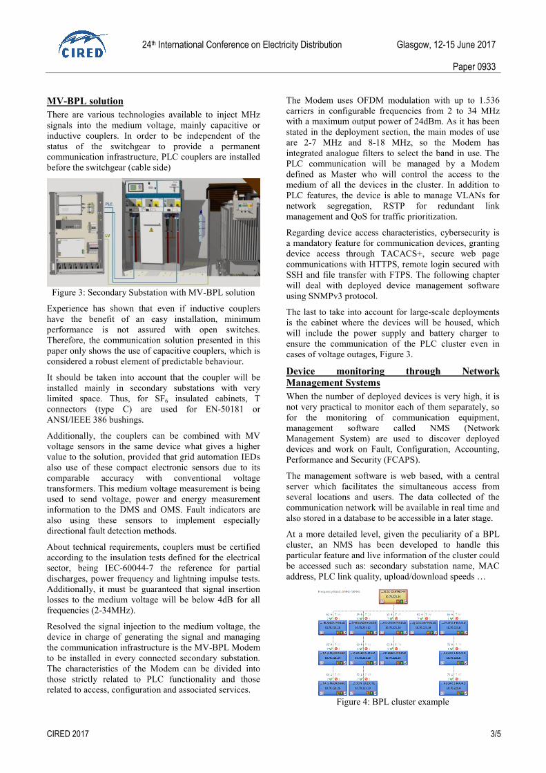
At a more detailed level, given the peculiarity of a BPL
cluster, an NMS has been developed to handle this
particular feature and live information of the cluster could
be accessed such as: secondary substation name, MAC
address, PLC link quality, upload/download speeds …
Figure 4: BPL cluster example

24th International Conference on Electricity Distribution Glasgow, 12-15 June 2017
Paper 0933
CIRED 2017 4/5
MV-BPL ROLL OUT EXPERIENCE
Deployment good practices
The following sequence is the installation process of a
BPL link between two secondary substations:
• De-energization of the MV cable: depending on the
coupling method and the switch gear type, the
installation could be done without de-energization,
but normally it is necessary to do so for safety
reasons.
• Phase identification: establish a method to identify
that both ends of the MV line in which the couplers
are installed, correspond with the same cable.
• Installation of couplers and BPL communication
devices, following the installation recommendations
of the manufacturers.
• Connection between BPL device and the coupler
through RG58 coaxial cable. It is important to test
that the coaxial cable is properly done.
• Perform first connectivity verification of the BPL
link. A conservative recommendation should be to
obtain at least minimum physical speed of 10Mbps
Tx and Rx in all positions of the MV circuit breaker
(normally equivalent to SNR >15dB in both
directions).
Following the deployment rules and if the installation is
properly done, the BPL link should show good
performance.
Operation and maintenance
After commissioning of a new BPL cluster in the
network, the NMS will help to supervise the BPL devices
in its life-cycle in the network. But the grid is not static,
and the boundary conditions could change over time.
This might suppose that an operating BPL link becomes
non-operating. This is due to new factors originally non
present during installation phase:
• BPL device becomes unavailable due to
miscellaneous hardware or software factors (such us
high temperature, component degradation,
misconfiguration, …). Certainly in BPL equipment
this means a very low percentage of problems
compared to other types of telecommunication
technologies that are installed in the secondary
substations. This is due to the fact that in a native
way and by design, the BPL equipment was
conceived to be installed in electrical environments.
• Unexpected noise source or BPL interference
(producing low SNR): most common noises in real
deployments were produced by other electronic
devices installed in secondary substations such as
battery chargers, RTUs, relays or metering devices.
This can be solved by simply replacing the damaged
components or applying filtering methods.
• BPL Link degradation/fault due to: increase of
attenuation (new splice), medium voltage cable cut-
off, coupler unit fault or degradation, coaxial cabling
or connectors degradation due to miscellaneous
factors (humidity, ..) leading to impedance mismatch.
This might imply revision and optimization of the
cabling and the coupler installation.
• For new secondary substation created in the
electrical grid that affects the BPL topology, review
of BPL planning would be needed.
Troubleshooting strategies
Despite planning efforts, a few BPL links considered
feasible in theory, might show throughput values below
expected thresholds. The most common cases found and
the typical solutions are shown in the following table [6]:
Table 3: Typical situations in BPL links to troubleshoot
ON-GOING RESEARCH TOPICS
In addition to continued cybersecurity developments to
ensure secure communications when managing remotely
the devices and high availability solutions to provide a set
of mechanisms intended to solve the different fault cases
that might occur, the main on-going research topic deals
with overhead lines.
Category Symptoms Solution
Impedance
mismatch • Low received power
levels (OFDM
carriers)
• Asymmetrical (both
ends) received power
levels (OFDM
carriers)
• Cabling
(connectors)
problem solving
• Coupling unit
installation
improvement
(cable distance
shortening)
Saturation • Short MV cables
distance
• Low performance
(throughput)
• Reception automatic
gain control, 0
• Attenuation by
software
• Attenuation using
external hardware
High
Attenuatio
n
• High MV cables
distance
• Low performance
(throughput)
• Low SNR
• Reception automatic
gain control,
maximum
• Cabling and
coupling units
connection
improvement
• MV cable phase
change
Noise • Low performance
(throughput)
• Low SNR
• Reception automatic
gain control,
maximum
• Abnormal BPL
received signal
spectrum
• Cabling and
coupling units
connection
improvement
• Noise filtering
(e.g., mains)

24th International Conference on Electricity Distribution Glasgow, 12-15 June 2017
Paper 0933
CIRED 2017 5/5
MV-BPL through overhead lines
The paper has presented MV-BPL communication
solution as a mature technology for deployments on
underground cables, where a set of rules is defined that
ensures a communication service with no previous onsite
assessment.
However, in order to enable a more widespread
deployment of the BPL technology also for sub-urban
and rural environments, it will be necessary to apply the
technology to overhead wires. Within an initial pilot
project, extensive point to point measurements,
channel/noise modelling and a pilot installation test have
been performed to validate the analysis.
Figure 5: Overhead point to point measurements
Up to 65 point to point channel, noise and throughput
(Mbit/s) measurements have been performed on a mixed
medium voltage network which included underground
cables and overhead wires as well as underground to
overhead transitions. Throughput results can be
summarized in Figure 6 and channel and noise
measurements have been mathematically modelled to
calculate recommended maximum distances.
Figure 6: Throughput Vs Distance
A very summarized analysis of the 65 measurements
compiled in Figure 6, would be that in the best scenario
communication was possible up to about 6 km and in the
worst case around 2.5 km. As we are targeting the
definition of conservative deployment rules without any
prior assessment, it is not realistic to think and promote
that the technology reaches up to 6 km but to conclude
that we are able to cope with overhead links up to 2km no
matter the amount of branches on the overhead line. A
further important result is that the transition point from
underground to overhead provides very little additional
attenuation of the BPL signal.
As channel attenuation and noise were also measured and
modelled mathematically, a model of the Signal to Noise
Ratio (SNR) versus distance and frequency could also be
developed. The SNR model was then used together with a
model of the underlying BPL technology in order to
determine the maximum theoretical achievable distances
given the following assumptions:
1. Desired minimum PHY data rate: 10 Mbps
2. Transmit Modem PSD: -50 dBm/Hz
The results of the analysis for the different BPL channels
are shown in Table 4. As can be seen the results are very
similar to the results of the throughput measurements
shown above.
Maximum distance for mode 2-7MHz 2.3 km
Maximum distance for mode 8-18MHz 2.3 km
Table 4: Maximum theoretical distances
These assumptions were validated in a field trial with a
complete BPL cluster and it is expected to keep installing
devices according to these deployment rules.
CONCLUSION
A communications infrastructure has been presented that
brings together information from several neighboring
secondary substations, showing the conditions and
necessary elements that have facilitated the deployment
of thousands of installations for AMI and grid automation
in underground networks.
In order to cover all types of electrical networks, the
feasibility of using MV-BPL technology has been
demonstrated for future deployments that may include
mixed and overhead networks.
REFERENCES
[1] H. BAROJA, J. A. SANCHEZ, I. MARTIN, “Nuevos
conceptos para automatización de centros de
transformación MT/BT. Soluciones: Funciones y
productos”, CLADE 2012.
[2] J. MARTI, C. RICHTER, E. GABRIEL, “Automatic Grid
Recovery (AGR/ARA), the virtual operator”, CIRED2015.
[3] G. AMANN, L. ANDERSSON, A. AMEZUA,
“Resultados experimentales de tecnologías de
comunicaciones para Smart Grid”, CIDEL 2014.
[4] A. AMEZUA, M. MAURER, L. ANDERSON, A.
SENDIN, J. SIMON, M. SOLAZ, “MVBPL – Reliable,
future proof and cost efficient”, CIRED 2015.
[5] M. SOLAZ, J. SIMON, A. SENDIN, L ANDERSSON, M.
MAURER, "High Availability Solution for MV-BPL
Communication Networks",IEEE ISPLC 2014.
[6] A. SENDIN, M. SANCHEZ-FORNIE, I BERGANZA, J.
SIMON, I. URRUTIA, "Telecommunication Networks for
the Smart Grid ", Artech House, 2016.