Comparison of Powertrain Configuration Options for Plug … - Papers/powertrain/SAE...
12
Page 1 of 12 SAE 2012-01-1027 Comparison of Powertrain Configuration Options for Plug-in HEVs from a Fuel Economy Perspective Namdoo Kim, Jason Kwon, and Aymeric Rousseau Argonne National Laboratory Copyright © 2012 SAE International ABSTRACT The first commercially available plug-in hybrid electric vehicle (PHEV), the General Motors (GM) Volt, was introduced into the market in mid-December 2010. The Volt uses a series-split powertrain architecture, which provides benefits over the series architecture that typically has been considered for use in electric-range extended vehicles (EREVs). A specialized EREV powertrain, called the Voltec, drives the Volt through its entire range of speed and acceleration with battery power alone and within the limit of battery energy, thereby displacing more fuel with electricity than a PHEV, which characteristically blends electric and engine power together during driving. This paper assesses the benefits and drawbacks of these two different plug-in hybrid electric architectures (series versus series-split) by comparing component sizes, system efficiency, and fuel consumption over urban and highway drive cycles. Based on dynamic models, a detailed component control algorithm was developed for each PHEV. In particular, for the GM Voltec, a control algorithm was proposed for both electric machines to achieve optimal engine operation. The powertrain components were sized to meet all-electric-range, performance, and grade capacity requirements. This paper presents and compares the impact of these two different powertrain configurations on component size and fuel consumption. INTRODUCTION Plug-in hybrid vehicles (PHEVs) combine an internal combustion engine (ICE) and an electrical energy/power source that is composed of a battery and one or two electric machines. Compared with the common hybrid electric vehicle (HEV), a PHEV has greater potential to improve fuel efficiency and reduce emissions, since it allows full electric driving and can obtain electric power easily from the home electricity grid [1]. The PHEV is also competent for long-distance driving with its HEV function. The Volt is manufactured by the Chevrolet division of General Motors (GM). This sedan-type PHEV was rated in model-year 2011 by the U.S. Environmental Protection Agency. According to GM, the Volt can travel 20 to 50 miles on its lithium-ion battery of 16 kWh. The GM Voltec powertrain architecture provides four modes of operation, including two that are unique and maximize the Volt’s efficiency and performance. The electric transaxle has been specially designed to enable patented operating modes both to improve the electric driving range when operating as a battery electric vehicle and to reduce fuel consumption when extending the range by operating with an ICE. The Voltec powertrain introduces a unique, two-motor electric vehicle (EV) driving mode that allows both the driving motor and the generator to provide tractive effort while simultaneously reducing electric motor speeds and the total associated electric motor losses. For HEV operation, the Voltec transaxle uses the same hardware that enables one-motor and two-motor operation to provide the completely decoupled action of a pure series hybrid, as well as a more efficient flow of power with decoupled action for driving at light load and high vehicle speed [2, 3]. When designing a vehicle for a specific application, the goal is to select the powertrain configuration that maximizes the fuel displaced and yet minimizes the sizes of components. The power-split system is the most commonly used system in currently available hybrid vehicles. However, the design of the power-split system for the PHEV is based on the blended strategy, and it has a relatively short electric driving range [4]. The series configuration for the PHEV, on the other hand, is often considered to be closer to a pure electric vehicle when compared with a split configuration. In this study, a comparative analysis is conducted on the Voltec and a pure series for the PHEV. Two vehicle powertrain configurations are sized to achieve similar performance for all-electric range (AER) approaches based on midsize vehicle applications. The component sizes and the fuel economy of each option are examined.
Transcript of Comparison of Powertrain Configuration Options for Plug … - Papers/powertrain/SAE...

Page 1 of 12
SAE 2012-01-1027
Comparison of Powertrain Configuration Options for Plug-in HEVs
from a Fuel Economy Perspective
Namdoo Kim, Jason Kwon, and Aymeric Rousseau Argonne National Laboratory
Copyright © 2012 SAE International
ABSTRACT
The first commercially available plug-in hybrid electric vehicle (PHEV), the General Motors (GM) Volt, was introduced into the
market in mid-December 2010. The Volt uses a series-split powertrain architecture, which provides benefits over the series
architecture that typically has been considered for use in electric-range extended vehicles (EREVs). A specialized EREV powertrain,
called the Voltec, drives the Volt through its entire range of speed and acceleration with battery power alone and within the limit of
battery energy, thereby displacing more fuel with electricity than a PHEV, which characteristically blends electric and engine power
together during driving. This paper assesses the benefits and drawbacks of these two different plug-in hybrid electric architectures
(series versus series-split) by comparing component sizes, system efficiency, and fuel consumption over urban and highway drive
cycles. Based on dynamic models, a detailed component control algorithm was developed for each PHEV. In particular, for the GM
Voltec, a control algorithm was proposed for both electric machines to achieve optimal engine operation. The powertrain components
were sized to meet all-electric-range, performance, and grade capacity requirements. This paper presents and compares the impact of
these two different powertrain configurations on component size and fuel consumption.
INTRODUCTION
Plug-in hybrid vehicles (PHEVs) combine an internal combustion engine (ICE) and an electrical energy/power source that is
composed of a battery and one or two electric machines. Compared with the common hybrid electric vehicle (HEV), a PHEV has
greater potential to improve fuel efficiency and reduce emissions, since it allows full electric driving and can obtain electric power
easily from the home electricity grid [1]. The PHEV is also competent for long-distance driving with its HEV function.
The Volt is manufactured by the Chevrolet division of General Motors (GM). This sedan-type PHEV was rated in model-year 2011 by
the U.S. Environmental Protection Agency. According to GM, the Volt can travel 20 to 50 miles on its lithium-ion battery of 16 kWh.
The GM Voltec powertrain architecture provides four modes of operation, including two that are unique and maximize the Volt’s
efficiency and performance. The electric transaxle has been specially designed to enable patented operating modes both to improve the
electric driving range when operating as a battery electric vehicle and to reduce fuel consumption when extending the range by
operating with an ICE. The Voltec powertrain introduces a unique, two-motor electric vehicle (EV) driving mode that allows both the
driving motor and the generator to provide tractive effort while simultaneously reducing electric motor speeds and the total associated
electric motor losses. For HEV operation, the Voltec transaxle uses the same hardware that enables one-motor and two-motor
operation to provide the completely decoupled action of a pure series hybrid, as well as a more efficient flow of power with decoupled
action for driving at light load and high vehicle speed [2, 3].
When designing a vehicle for a specific application, the goal is to select the powertrain configuration that maximizes the fuel
displaced and yet minimizes the sizes of components. The power-split system is the most commonly used system in currently
available hybrid vehicles. However, the design of the power-split system for the PHEV is based on the blended strategy, and it has a
relatively short electric driving range [4]. The series configuration for the PHEV, on the other hand, is often considered to be closer to
a pure electric vehicle when compared with a split configuration. In this study, a comparative analysis is conducted on the Voltec and
a pure series for the PHEV. Two vehicle powertrain configurations are sized to achieve similar performance for all-electric range
(AER) approaches based on midsize vehicle applications. The component sizes and the fuel economy of each option are examined.
Page 2 of 12
DESCRIPTION OF THE POWERTRAIN SYSTEM
PLUG-IN SERIES POWERTRAIN SYSTEM
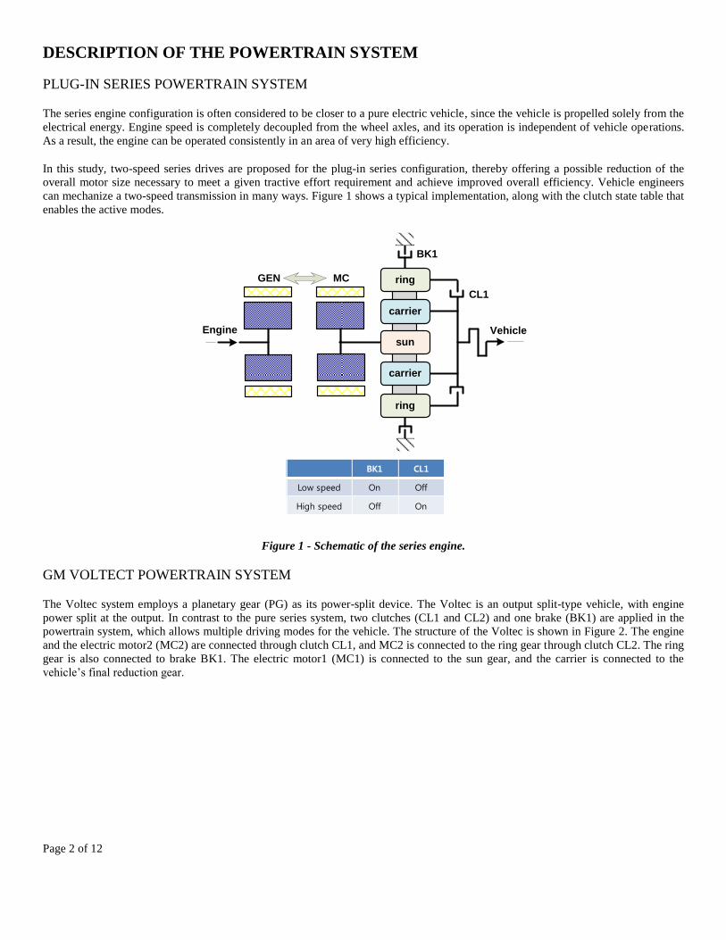
The series engine configuration is often considered to be closer to a pure electric vehicle, since the vehicle is propelled solely from the
electrical energy. Engine speed is completely decoupled from the wheel axles, and its operation is independent of vehicle operations.
As a result, the engine can be operated consistently in an area of very high efficiency.
In this study, two-speed series drives are proposed for the plug-in series configuration, thereby offering a possible reduction of the
overall motor size necessary to meet a given tractive effort requirement and achieve improved overall efficiency. Vehicle engineers
can mechanize a two-speed transmission in many ways. Figure 1 shows a typical implementation, along with the clutch state table that
enables the active modes.
Figure 1 - Schematic of the series engine.
GM VOLTECT POWERTRAIN SYSTEM
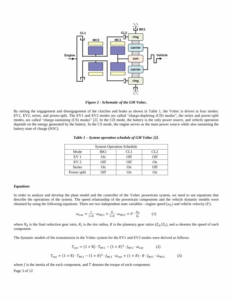
The Voltec system employs a planetary gear (PG) as its power-split device. The Voltec is an output split-type vehicle, with engine
power split at the output. In contrast to the pure series system, two clutches (CL1 and CL2) and one brake (BK1) are applied in the
powertrain system, which allows multiple driving modes for the vehicle. The structure of the Voltec is shown in Figure 2. The engine
and the electric motor2 (MC2) are connected through clutch CL1, and MC2 is connected to the ring gear through clutch CL2. The ring
gear is also connected to brake BK1. The electric motor1 (MC1) is connected to the sun gear, and the carrier is connected to the
vehicle’s final reduction gear.
BK1 CL1
Low speed On Off
High speed Off On
GEN MC
CL1
BK1
VehicleEnginesun
carrier
carrier
ring
ring
Page 3 of 12
Figure 2 - Schematic of the GM Voltec.
By setting the engagement and disengagement of the clutches and brake as shown in Table 1, the Voltec is driven in four modes:
EV1, EV2, series, and power-split. The EV1 and EV2 modes are called “charge-depleting (CD) modes”, the series and power-split
modes, are called “charge-sustaining (CS) modes” [2]. In the CD mode, the battery is the only power source, and vehicle operation
depends on the energy generated by the battery. In the CS mode, the engine serves as the main power source while also sustaining the
battery state of charge (SOC).
Table 1 – System operation schedule of GM Voltec [2].
System Operation Schedule
Mode BK1 CL1 CL2
EV 1 On Off Off
EV 2 Off Off On
Series On On Off
Power split Off On On
Equations
In order to analyze and develop the plant model and the controller of the Voltec powertrain system, we need to use equations that
describe the operations of the system. The speed relationship of the powertrain components and the vehicle dynamic models were
obtained by using the following equations. There are two independent state variables - engine speed ( ) and vehicle velocity ( ).
(1)
where is the final reduction gear ratio, is the tire radius, is the planetary gear ratios ( ), and denotes the speed of each
component.
The dynamic models of the transmission in the Voltec system for the EV1 and EV2 modes were derived as follows:
(2)
(3)
where is the inertia of the each component, and denotes the torque of each component.
MC2 MC1
CL2BK1
Engine
CL1
sun
carrier
carrier
ring
ring
Vehicle
Page 4 of 12
In the series mode, the dynamic equation of MC1 was the same as that shown in equation (2), and the dynamic equation of the engine
and MC2 was obtained as follows:
(4)
In the power split mode, the dynamic equation of MC1 was the same as that shown in equation (3), and the dynamic equation was
derived as:
(5)
Analysis of power-flow
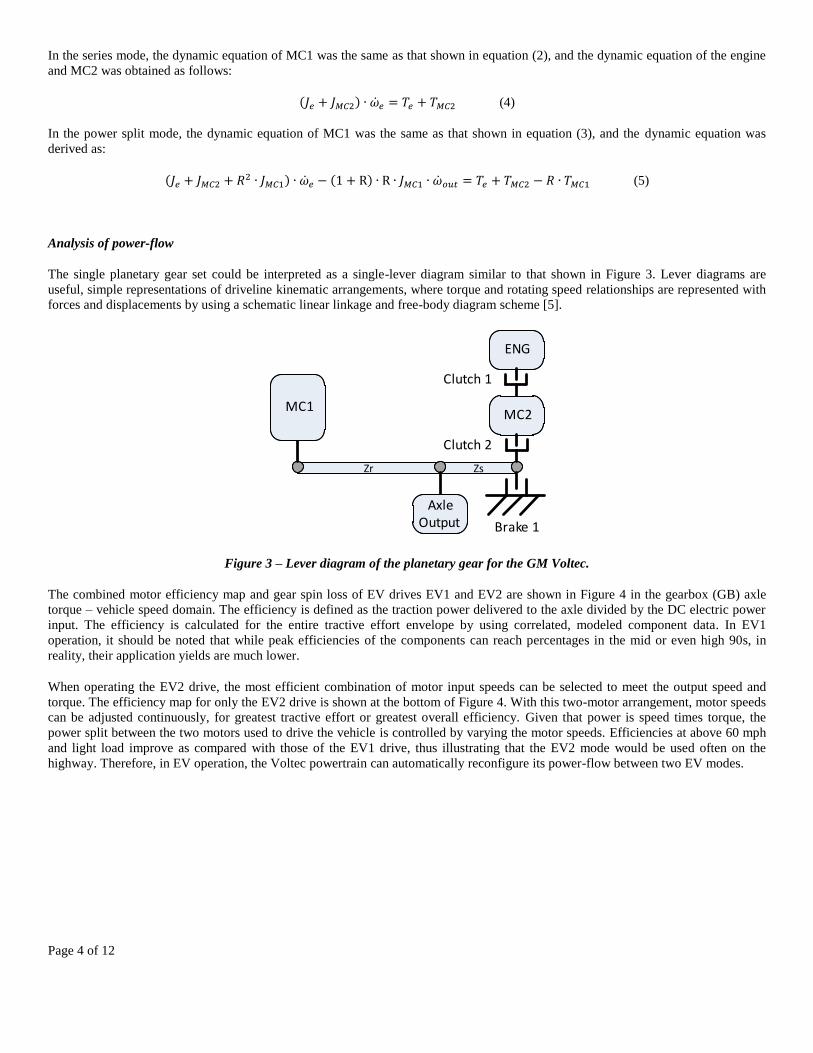
The single planetary gear set could be interpreted as a single-lever diagram similar to that shown in Figure 3. Lever diagrams are
useful, simple representations of driveline kinematic arrangements, where torque and rotating speed relationships are represented with
forces and displacements by using a schematic linear linkage and free-body diagram scheme [5].
Figure 3 – Lever diagram of the planetary gear for the GM Voltec.
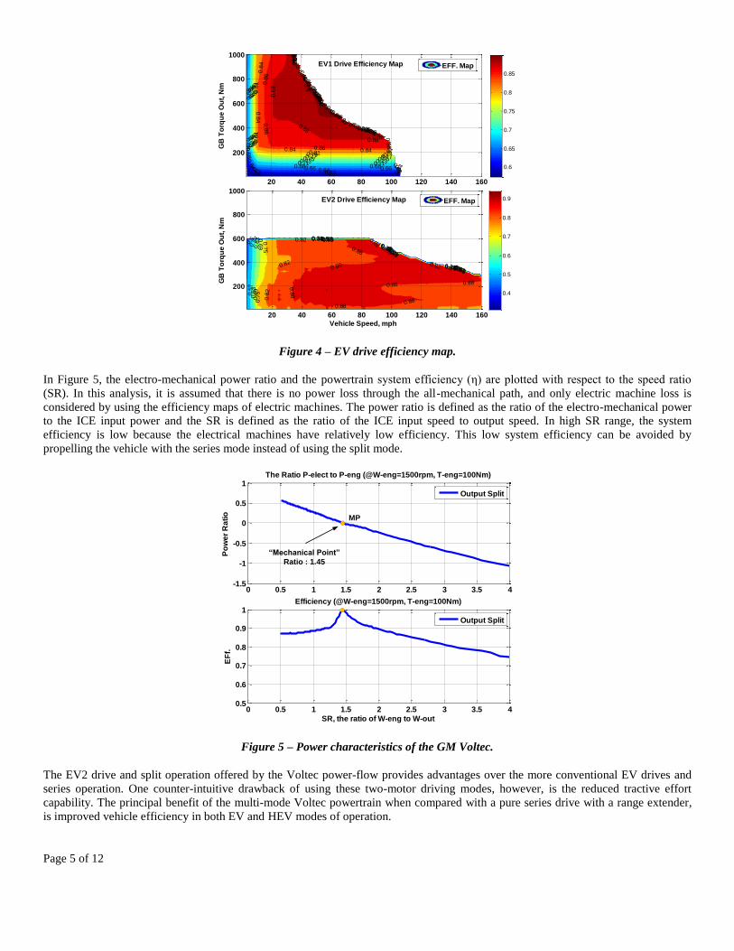
The combined motor efficiency map and gear spin loss of EV drives EV1 and EV2 are shown in Figure 4 in the gearbox (GB) axle
torque – vehicle speed domain. The efficiency is defined as the traction power delivered to the axle divided by the DC electric power
input. The efficiency is calculated for the entire tractive effort envelope by using correlated, modeled component data. In EV1
operation, it should be noted that while peak efficiencies of the components can reach percentages in the mid or even high 90s, in
reality, their application yields are much lower.
When operating the EV2 drive, the most efficient combination of motor input speeds can be selected to meet the output speed and
torque. The efficiency map for only the EV2 drive is shown at the bottom of Figure 4. With this two-motor arrangement, motor speeds
can be adjusted continuously, for greatest tractive effort or greatest overall efficiency. Given that power is speed times torque, the
power split between the two motors used to drive the vehicle is controlled by varying the motor speeds. Efficiencies at above 60 mph
and light load improve as compared with those of the EV1 drive, thus illustrating that the EV2 mode would be used often on the
highway. Therefore, in EV operation, the Voltec powertrain can automatically reconfigure its power-flow between two EV modes.
MC1MC2
ENG
AxleOutput
Clutch 1
Clutch 2
Brake 1
ZsZr
Page 5 of 12
Figure 4 – EV drive efficiency map.
In Figure 5, the electro-mechanical power ratio and the powertrain system efficiency (η) are plotted with respect to the speed ratio
(SR). In this analysis, it is assumed that there is no power loss through the all-mechanical path, and only electric machine loss is
considered by using the efficiency maps of electric machines. The power ratio is defined as the ratio of the electro-mechanical power
to the ICE input power and the SR is defined as the ratio of the ICE input speed to output speed. In high SR range, the system
efficiency is low because the electrical machines have relatively low efficiency. This low system efficiency can be avoided by
propelling the vehicle with the series mode instead of using the split mode.
Figure 5 – Power characteristics of the GM Voltec.
The EV2 drive and split operation offered by the Voltec power-flow provides advantages over the more conventional EV drives and
series operation. One counter-intuitive drawback of using these two-motor driving modes, however, is the reduced tractive effort
capability. The principal benefit of the multi-mode Voltec powertrain when compared with a pure series drive with a range extender,
is improved vehicle efficiency in both EV and HEV modes of operation.
0.6
0.6
0.6
0.6
0.60.6
0.6
2
0.62
0.62
0.62
0.620.62
0.6
4
0.6
4
0.64
0.640.64
0.64
0.6
6
0.6
6
0.66
0.660.66
0.6
6
0.68
0.68
0.68
0.680.68
0.6
8
0.6
8
0.7
1
0.7
1
0.71
0.710.71
0.7
1
0.7
1
0.7
3
0.73
0.73
0.730.73
0.7
3
0.7
3
0.75
0.7
5
0.75
0.750.75
0.7
5
0.7
5
0.7
7
0.7
7
0.77
0.770.77
0.7
70.7
7
0.7
9
0.79
0.790.79
0.7
90.7
9
0.81
0.810.
810.81
0.8
10.8
1
0.84
0.8
4
0.84
0.840.84
0.8
4
0.8
4
0.86
0.86
0.8
6
0.86
0.8
6
0.8
6
0.8
8
0.8
8
0.88
0.88
0.88
0.8
8
0.9
0.9
EV1 Drive Efficiency Map
GB
To
rqu
e O
ut,
Nm
20 40 60 80 100 120 140 160
200
400
600
800
1000
EFF. Map
0.6
0.65
0.7
0.75
0.8
0.85
0.310.31
0.31
0.380.38
0.38
0.44
0.44
0.44
0.5 0.5
0.5
0.5
0.5
70.
57 0.57
0.57
0.57
0.6
30.6
3 0.63
0.63
0.63
0.6
9
0.6
9
0.69
0.69
0.69
0.7
5
0.7
5
0.75
0.75
0.750.82
0.82 0.82
0.820.8
20.88
0.880.88
0.88
0.880.88
0.880.88
0.8
8
EV2 Drive Efficiency Map
Vehicle Speed, mph
GB
To
rqu
e O
ut,
Nm
20 40 60 80 100 120 140 160
200
400
600
800
1000
EFF. Map
0.4
0.5
0.6
0.7
0.8
0.9
0 0.5 1 1.5 2 2.5 3 3.5 4-1.5
-1
-0.5
0
0.5
1
Po
we
r R
ati
o
The Ratio P-elect to P-eng (@W-eng=1500rpm, T-eng=100Nm)
Output Split
0 0.5 1 1.5 2 2.5 3 3.5 40.5
0.6
0.7
0.8
0.9
1
SR, the ratio of W-eng to W-out
EF
f.
Efficiency (@W-eng=1500rpm, T-eng=100Nm)
Output Split
MP
“Mechanical Point”
Ratio : 1.45
Page 6 of 12
COMPONENT SIZING
MODELING THE VEHICLE IN AUTONOMIE
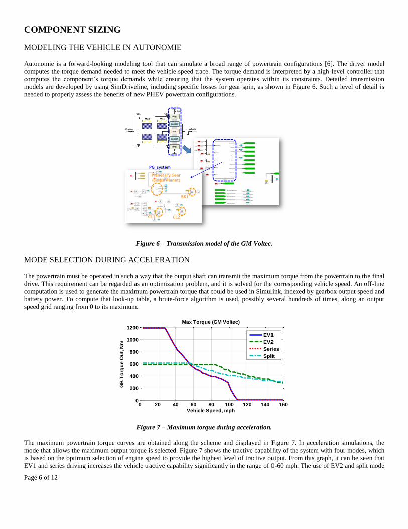
Autonomie is a forward-looking modeling tool that can simulate a broad range of powertrain configurations [6]. The driver model
computes the torque demand needed to meet the vehicle speed trace. The torque demand is interpreted by a high-level controller that
computes the component’s torque demands while ensuring that the system operates within its constraints. Detailed transmission
models are developed by using SimDriveline, including specific losses for gear spin, as shown in Figure 6. Such a level of detail is
needed to properly assess the benefits of new PHEV powertrain configurations.
Figure 6 – Transmission model of the GM Voltec.
MODE SELECTION DURING ACCELERATION
The powertrain must be operated in such a way that the output shaft can transmit the maximum torque from the powertrain to the final
drive. This requirement can be regarded as an optimization problem, and it is solved for the corresponding vehicle speed. An off-line
computation is used to generate the maximum powertrain torque that could be used in Simulink, indexed by gearbox output speed and
battery power. To compute that look-up table, a brute-force algorithm is used, possibly several hundreds of times, along an output
speed grid ranging from 0 to its maximum.
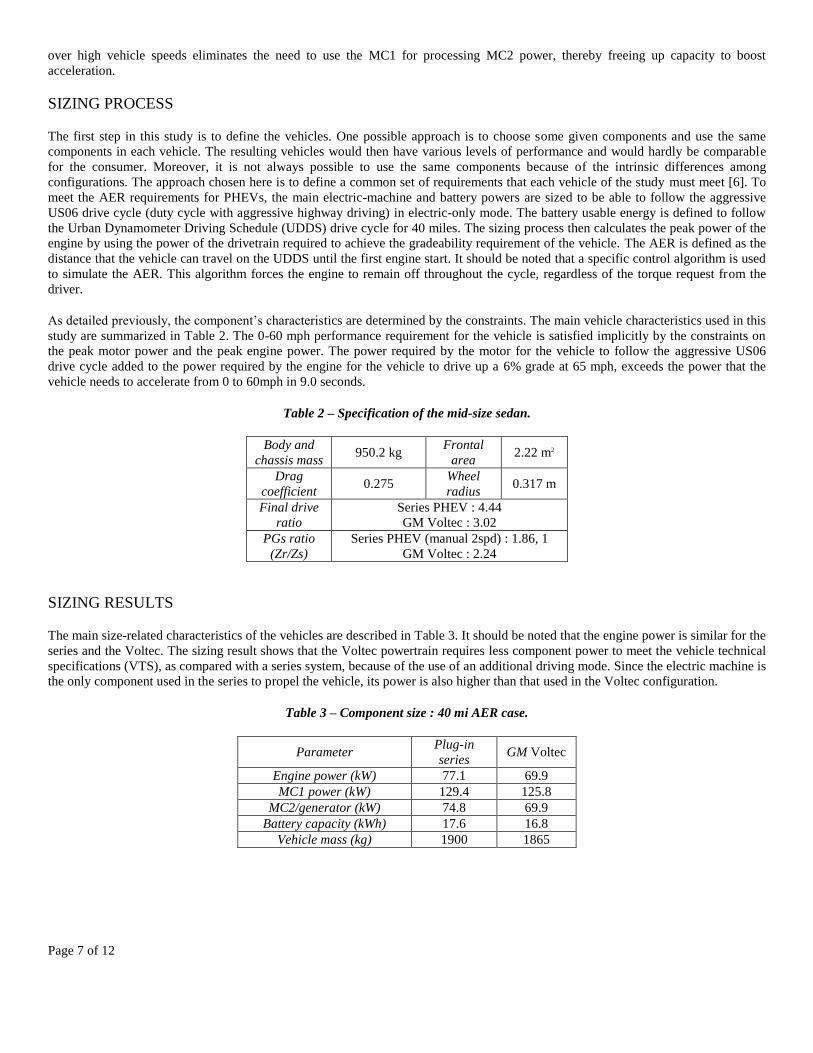
Figure 7 – Maximum torque during acceleration.
The maximum powertrain torque curves are obtained along the scheme and displayed in Figure 7. In acceleration simulations, the
mode that allows the maximum output torque is selected. Figure 7 shows the tractive capability of the system with four modes, which
is based on the optimum selection of engine speed to provide the highest level of tractive output. From this graph, it can be seen that
EV1 and series driving increases the vehicle tractive capability significantly in the range of 0-60 mph. The use of EV2 and split mode
MC2 MC1
CL2BK1
Engine
CL1
sun
carrier
carrier
ring
ring
Vehicle
PG_system
CL1
Planetary Gear
(Single Planet)
CL2
BK1
0 20 40 60 80 100 120 140 1600
200
400
600
800
1000
1200
Vehicle Speed, mph
GB
To
rqu
e O
ut,
Nm
Max Torque (GM Voltec)
EV1
EV2
Series
Split
Page 7 of 12
over high vehicle speeds eliminates the need to use the MC1 for processing MC2 power, thereby freeing up capacity to boost
acceleration.
SIZING PROCESS
The first step in this study is to define the vehicles. One possible approach is to choose some given components and use the same
components in each vehicle. The resulting vehicles would then have various levels of performance and would hardly be comparable
for the consumer. Moreover, it is not always possible to use the same components because of the intrinsic differences among
configurations. The approach chosen here is to define a common set of requirements that each vehicle of the study must meet [6]. To
meet the AER requirements for PHEVs, the main electric-machine and battery powers are sized to be able to follow the aggressive
US06 drive cycle (duty cycle with aggressive highway driving) in electric-only mode. The battery usable energy is defined to follow
the Urban Dynamometer Driving Schedule (UDDS) drive cycle for 40 miles. The sizing process then calculates the peak power of the
engine by using the power of the drivetrain required to achieve the gradeability requirement of the vehicle. The AER is defined as the
distance that the vehicle can travel on the UDDS until the first engine start. It should be noted that a specific control algorithm is used
to simulate the AER. This algorithm forces the engine to remain off throughout the cycle, regardless of the torque request from the
driver.
As detailed previously, the component’s characteristics are determined by the constraints. The main vehicle characteristics used in this
study are summarized in Table 2. The 0-60 mph performance requirement for the vehicle is satisfied implicitly by the constraints on
the peak motor power and the peak engine power. The power required by the motor for the vehicle to follow the aggressive US06
drive cycle added to the power required by the engine for the vehicle to drive up a 6% grade at 65 mph, exceeds the power that the
vehicle needs to accelerate from 0 to 60mph in 9.0 seconds.
Table 2 – Specification of the mid-size sedan.
Body and
chassis mass 950.2 kg
Frontal
area 2.22 m2
Drag
coefficient 0.275
Wheel
radius 0.317 m
Final drive
ratio
Series PHEV : 4.44
GM Voltec : 3.02
PGs ratio
(Zr/Zs)
Series PHEV (manual 2spd) : 1.86, 1
GM Voltec : 2.24
SIZING RESULTS
The main size-related characteristics of the vehicles are described in Table 3. It should be noted that the engine power is similar for the
series and the Voltec. The sizing result shows that the Voltec powertrain requires less component power to meet the vehicle technical
specifications (VTS), as compared with a series system, because of the use of an additional driving mode. Since the electric machine is
the only component used in the series to propel the vehicle, its power is also higher than that used in the Voltec configuration.
Table 3 – Component size : 40 mi AER case.
Parameter Plug-in
series GM Voltec
Engine power (kW) 77.1 69.9
MC1 power (kW) 129.4 125.8
MC2/generator (kW) 74.8 69.9
Battery capacity (kWh) 17.6 16.8
Vehicle mass (kg) 1900 1865
Page 8 of 12
CONTROL STRATEGY
MODE SHIFT STRATEGY
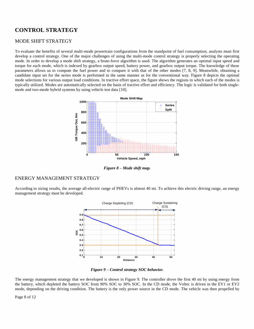
To evaluate the benefits of several multi-mode powertrain configurations from the standpoint of fuel consumption, analysts must first
develop a control strategy. One of the major challenges of using the multi-mode control strategy is properly selecting the operating
mode. In order to develop a mode shift strategy, a brute-force algorithm is used. The algorithm generates an optimal input speed and
torque for each mode, which is indexed by gearbox output speed, battery power, and gearbox output torque. The knowledge of these
parameters allows us to compute the fuel power and to compare it with that of the other modes [7, 8, 9]. Meanwhile, obtaining a
candidate input set for the series mode is performed in the same manner as for the conventional way. Figure 8 depicts the optimal
mode selections for various output load conditions. In tractive effort space, the figure shows the regions in which each of the modes is
typically utilized. Modes are automatically selected on the basis of tractive effort and efficiency. The logic is validated for both single-
mode and two-mode hybrid systems by using vehicle test data [10].
Figure 8 – Mode shift map.
ENERGY MANAGEMENT STRATEGY
According to sizing results, the average all-electric range of PHEVs is almost 40 mi. To achieve this electric driving range, an energy
management strategy must be developed.
Figure 9 – Control strategy SOC behavior.
The energy management strategy that we developed is shown in Figure 9. The controller drove the first 40 mi by using energy from
the battery, which depleted the battery SOC from 90% SOC to 30% SOC. In the CD mode, the Voltec is driven in the EV1 or EV2
mode, depending on the driving condition. The battery is the only power source in the CD mode. The vehicle was then propelled by
0 50 100 150
200
400
600
800
1000Mode Shift Map
Vehicle Speed, mph
GB
To
rqu
e O
ut,
Nm
Series
Split
0 10 20 30 40 500.1
0.2
0.3
0.4
0.5
0.6
0.7
0.8
0.9
Distance
SO
C
Charge Depleting (CD) Charge Sustaining
(CS)
Page 9 of 12
using a combination of the engine and battery while the SOC was maintained. This is the CS operation of the strategy. By using this
algorithm, we obtain better fuel efficiency by consuming as much electric energy as possible.
For the Voltec configuration, the driving mode is an integral part of the energy management strategy. As discussed previously, the
transmission efficiency map of the EV1 and EV2 modes can be calculated by considering the motor efficiency and transmission loss.
On the basis of the efficiency map, the shift map can also be constructed for the CD mode. As a result, the EV1 or EV2 mode can be
selected by the battery SOC, vehicle velocity, and drive demand torque.
SIMULATION RESULTS
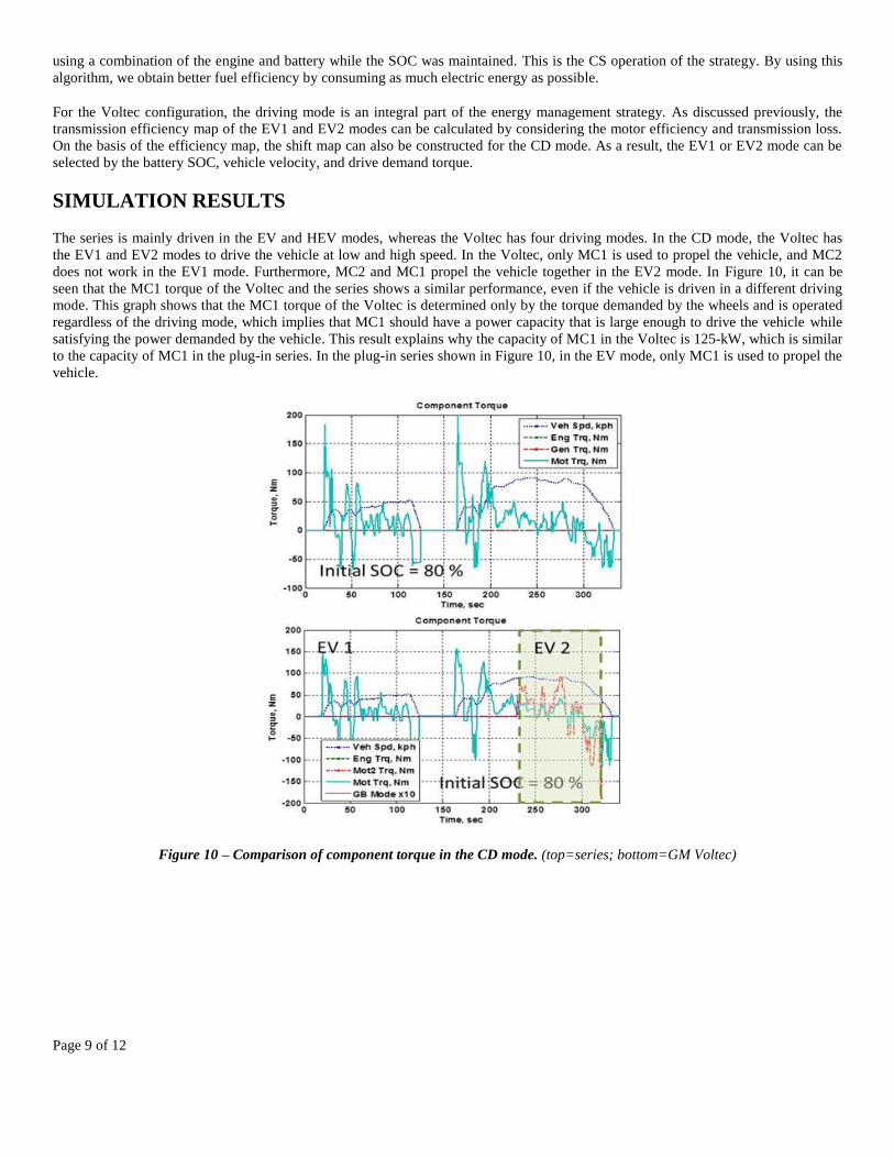
The series is mainly driven in the EV and HEV modes, whereas the Voltec has four driving modes. In the CD mode, the Voltec has
the EV1 and EV2 modes to drive the vehicle at low and high speed. In the Voltec, only MC1 is used to propel the vehicle, and MC2
does not work in the EV1 mode. Furthermore, MC2 and MC1 propel the vehicle together in the EV2 mode. In Figure 10, it can be
seen that the MC1 torque of the Voltec and the series shows a similar performance, even if the vehicle is driven in a different driving
mode. This graph shows that the MC1 torque of the Voltec is determined only by the torque demanded by the wheels and is operated
regardless of the driving mode, which implies that MC1 should have a power capacity that is large enough to drive the vehicle while
satisfying the power demanded by the vehicle. This result explains why the capacity of MC1 in the Voltec is 125-kW, which is similar
to the capacity of MC1 in the plug-in series. In the plug-in series shown in Figure 10, in the EV mode, only MC1 is used to propel the
vehicle.
Figure 10 – Comparison of component torque in the CD mode. (top=series; bottom=GM Voltec)
Page 10 of 12
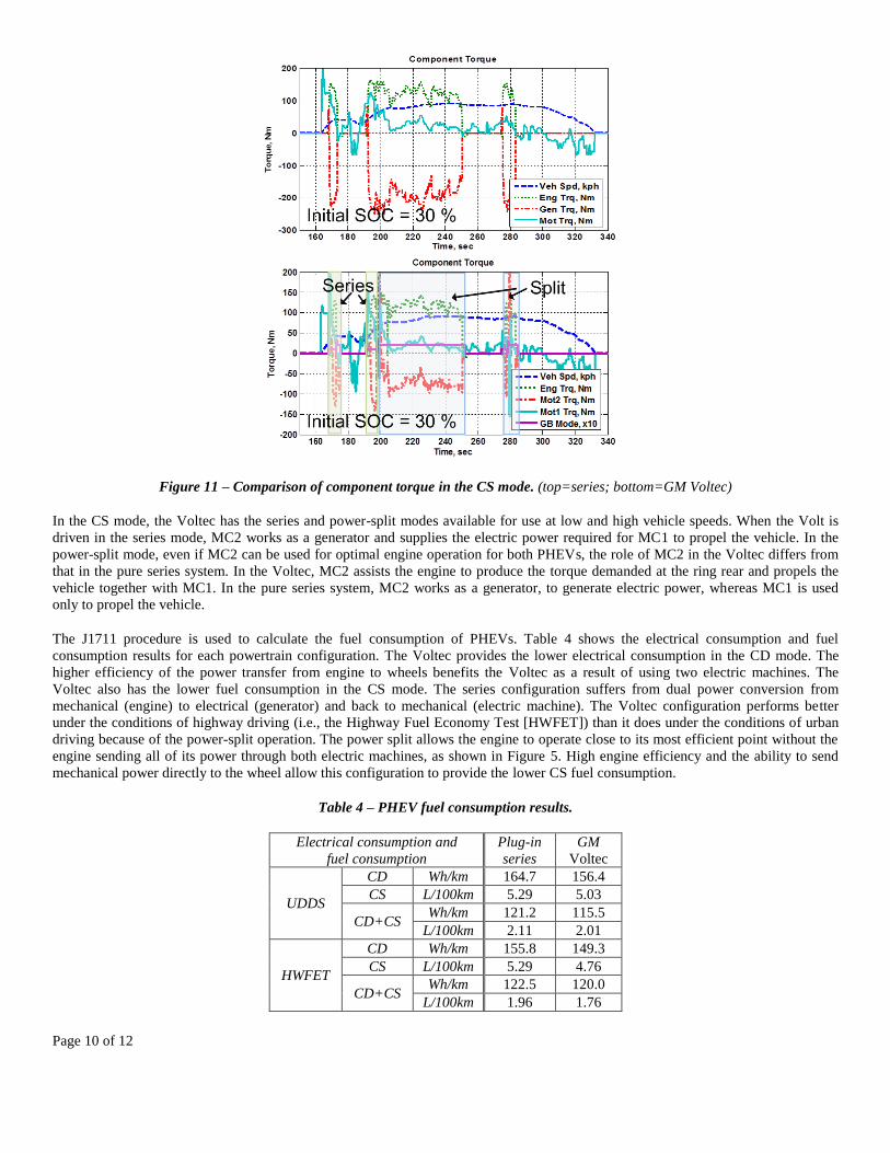
Figure 11 – Comparison of component torque in the CS mode. (top=series; bottom=GM Voltec)
In the CS mode, the Voltec has the series and power-split modes available for use at low and high vehicle speeds. When the Volt is
driven in the series mode, MC2 works as a generator and supplies the electric power required for MC1 to propel the vehicle. In the
power-split mode, even if MC2 can be used for optimal engine operation for both PHEVs, the role of MC2 in the Voltec differs from
that in the pure series system. In the Voltec, MC2 assists the engine to produce the torque demanded at the ring rear and propels the
vehicle together with MC1. In the pure series system, MC2 works as a generator, to generate electric power, whereas MC1 is used
only to propel the vehicle.
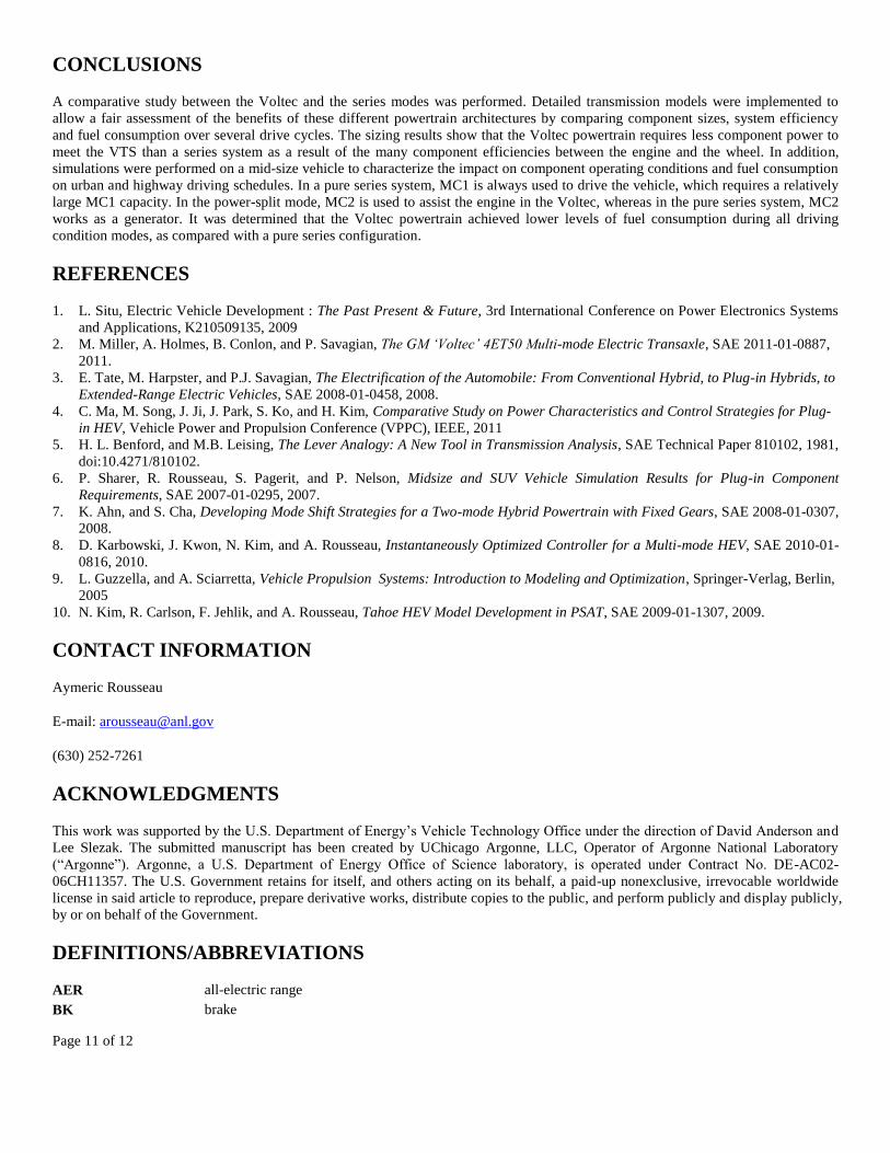
The J1711 procedure is used to calculate the fuel consumption of PHEVs. Table 4 shows the electrical consumption and fuel
consumption results for each powertrain configuration. The Voltec provides the lower electrical consumption in the CD mode. The
higher efficiency of the power transfer from engine to wheels benefits the Voltec as a result of using two electric machines. The
Voltec also has the lower fuel consumption in the CS mode. The series configuration suffers from dual power conversion from
mechanical (engine) to electrical (generator) and back to mechanical (electric machine). The Voltec configuration performs better
under the conditions of highway driving (i.e., the Highway Fuel Economy Test [HWFET]) than it does under the conditions of urban
driving because of the power-split operation. The power split allows the engine to operate close to its most efficient point without the
engine sending all of its power through both electric machines, as shown in Figure 5. High engine efficiency and the ability to send
mechanical power directly to the wheel allow this configuration to provide the lower CS fuel consumption.
Table 4 – PHEV fuel consumption results.
Electrical consumption and
fuel consumption
Plug-in
series
GM
Voltec
UDDS
CD Wh/km 164.7 156.4
CS L/100km 5.29 5.03
CD+CS Wh/km 121.2 115.5
L/100km 2.11 2.01
HWFET
CD Wh/km 155.8 149.3
CS L/100km 5.29 4.76
CD+CS Wh/km 122.5 120.0
L/100km 1.96 1.76
Page 11 of 12
CONCLUSIONS
A comparative study between the Voltec and the series modes was performed. Detailed transmission models were implemented to
allow a fair assessment of the benefits of these different powertrain architectures by comparing component sizes, system efficiency
and fuel consumption over several drive cycles. The sizing results show that the Voltec powertrain requires less component power to
meet the VTS than a series system as a result of the many component efficiencies between the engine and the wheel. In addition,
simulations were performed on a mid-size vehicle to characterize the impact on component operating conditions and fuel consumption
on urban and highway driving schedules. In a pure series system, MC1 is always used to drive the vehicle, which requires a relatively
large MC1 capacity. In the power-split mode, MC2 is used to assist the engine in the Voltec, whereas in the pure series system, MC2
works as a generator. It was determined that the Voltec powertrain achieved lower levels of fuel consumption during all driving
condition modes, as compared with a pure series configuration.
REFERENCES
1. L. Situ, Electric Vehicle Development : The Past Present & Future, 3rd International Conference on Power Electronics Systems
and Applications, K210509135, 2009
2. M. Miller, A. Holmes, B. Conlon, and P. Savagian, The GM ‘Voltec’ 4ET50 Multi-mode Electric Transaxle, SAE 2011-01-0887,
2011.
3. E. Tate, M. Harpster, and P.J. Savagian, The Electrification of the Automobile: From Conventional Hybrid, to Plug-in Hybrids, to
Extended-Range Electric Vehicles, SAE 2008-01-0458, 2008.
4. C. Ma, M. Song, J. Ji, J. Park, S. Ko, and H. Kim, Comparative Study on Power Characteristics and Control Strategies for Plug-
in HEV, Vehicle Power and Propulsion Conference (VPPC), IEEE, 2011
5. H. L. Benford, and M.B. Leising, The Lever Analogy: A New Tool in Transmission Analysis, SAE Technical Paper 810102, 1981,
doi:10.4271/810102.
6. P. Sharer, R. Rousseau, S. Pagerit, and P. Nelson, Midsize and SUV Vehicle Simulation Results for Plug-in Component
Requirements, SAE 2007-01-0295, 2007.
7. K. Ahn, and S. Cha, Developing Mode Shift Strategies for a Two-mode Hybrid Powertrain with Fixed Gears, SAE 2008-01-0307,
2008.
8. D. Karbowski, J. Kwon, N. Kim, and A. Rousseau, Instantaneously Optimized Controller for a Multi-mode HEV, SAE 2010-01-
0816, 2010.
9. L. Guzzella, and A. Sciarretta, Vehicle Propulsion Systems: Introduction to Modeling and Optimization, Springer-Verlag, Berlin,
2005
10. N. Kim, R. Carlson, F. Jehlik, and A. Rousseau, Tahoe HEV Model Development in PSAT, SAE 2009-01-1307, 2009.
CONTACT INFORMATION
Aymeric Rousseau
E-mail: [email protected]
(630) 252-7261
ACKNOWLEDGMENTS
This work was supported by the U.S. Department of Energy’s Vehicle Technology Office under the direction of David Anderson and
Lee Slezak. The submitted manuscript has been created by UChicago Argonne, LLC, Operator of Argonne National Laboratory
(“Argonne”). Argonne, a U.S. Department of Energy Office of Science laboratory, is operated under Contract No. DE-AC02-
06CH11357. The U.S. Government retains for itself, and others acting on its behalf, a paid-up nonexclusive, irrevocable worldwide
license in said article to reproduce, prepare derivative works, distribute copies to the public, and perform publicly and display publicly,
by or on behalf of the Government.
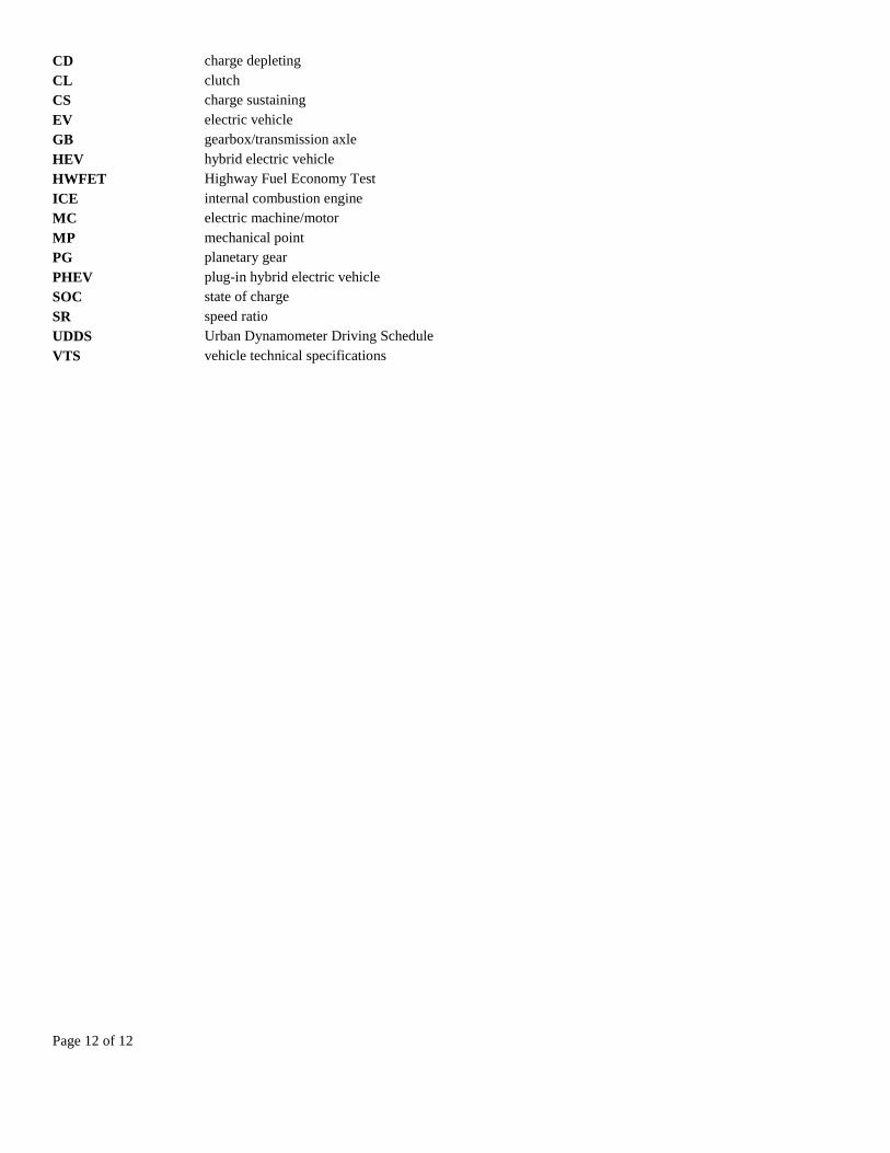
DEFINITIONS/ABBREVIATIONS
AER all-electric range
BK brake
Page 12 of 12
CD charge depleting
CL clutch
CS charge sustaining
EV electric vehicle
GB gearbox/transmission axle
HEV hybrid electric vehicle
HWFET Highway Fuel Economy Test
ICE internal combustion engine
MC electric machine/motor
MP mechanical point
PG planetary gear
PHEV plug-in hybrid electric vehicle
SOC state of charge
SR speed ratio
UDDS Urban Dynamometer Driving Schedule
VTS vehicle technical specifications