COMPARISON OF BASELOAD LIQUEFACTION PROCESSES
15
3.6–1 COMPARISON OF BASELOAD LIQUEFACTION PROCESSES COMPARAISON DES PROCEDES DE LIQUEFACTION DES USINES DE GRANDE CAPACITE K.J. Vink R. Klein Nagelvoort Shell International Oil Products, B.V. PO box 451, 2501 CM The Hague, The Netherlands ABSTRACT This paper summarises a recent comparison of five baseload LNG processes. The range of technology encompasses the Propane/MR process, a Cascade process, a version of the Dual Mixed Refrigerant process, a simple Single Mixed Refrigerant process and a pre-cooled Nitrogen expansion process. Each process was assessed on the basis of specific costs, specific power and fuel efficiency for a nominal 2 train liquefaction plant. The conclusions are: • The Propane/MR process appears to be the best choice within the premises of this comparison study, viz. large capacity LNG trains, employing air cooling in a tropical climate. Other promising processes are the Dual Mixed Refrigerant process and the Single Mixed refrigerant process. • The Cascade process appears to be relatively expensive, partly disadvantaged as it is by the study premises. Under colder conditions (arctic, water cooling), the costs and power requirements come closer to the Propane/MR process. • The pre-cooled Nitrogen Expansion process is not an economic choice for a large onshore application. It may be an alternative for smaller scale offshore applications. RESUME Cet article résume une récente comparaison de cinq procédés à GNL de base. La gamme de technologies inclut le procédé à propane/Réfrigérant Mélangé (RM), un procédé à cascade, une version du procédé à réfrigérant double mélangé, un procédé à réfrigérant unique mélangé et un procédé à expansion d’azote pré-réfroidi. Chaque procédé a fait l’objet d’une évaluation basée sure les coûts spécifiques, l’énergie spécifique et la rentabilité de carburant pour une usine de liquéfaction de 2 chaînes nominales.
Transcript of COMPARISON OF BASELOAD LIQUEFACTION PROCESSES

3.6–1
COMPARISON OF BASELOADLIQUEFACTION PROCESSES
COMPARAISON DES PROCEDES DE LIQUEFACTIONDES USINES DE GRANDE CAPACITE
K.J. VinkR. Klein Nagelvoort
Shell International Oil Products, B.V.PO box 451, 2501 CM
The Hague, The Netherlands
ABSTRACT
This paper summarises a recent comparison of five baseload LNG processes. Therange of technology encompasses the Propane/MR process, a Cascade process, a versionof the Dual Mixed Refrigerant process, a simple Single Mixed Refrigerant process and apre-cooled Nitrogen expansion process. Each process was assessed on the basis of specificcosts, specific power and fuel efficiency for a nominal 2 train liquefaction plant.
The conclusions are:
• The Propane/MR process appears to be the best choice within the premises of thiscomparison study, viz. large capacity LNG trains, employing air cooling in a tropicalclimate. Other promising processes are the Dual Mixed Refrigerant process and theSingle Mixed refrigerant process.
• The Cascade process appears to be relatively expensive, partly disadvantaged as it is bythe study premises. Under colder conditions (arctic, water cooling), the costs andpower requirements come closer to the Propane/MR process.
• The pre-cooled Nitrogen Expansion process is not an economic choice for a largeonshore application. It may be an alternative for smaller scale offshore applications.
RESUME
Cet article résume une récente comparaison de cinq procédés à GNL de base. Lagamme de technologies inclut le procédé à propane/Réfrigérant Mélangé (RM), unprocédé à cascade, une version du procédé à réfrigérant double mélangé, un procédé àréfrigérant unique mélangé et un procédé à expansion d’azote pré-réfroidi. Chaqueprocédé a fait l’objet d’une évaluation basée sure les coûts spécifiques, l’énergie spécifiqueet la rentabilité de carburant pour une usine de liquéfaction de 2 chaînes nominales.

3.6–2
Les conclusions sont:
• Le procédé à propane/RM s’est révèlé la meilleure alternative dans le cadre de l’étudecomparative, c’est-a-dire des chaînes de GNL de grande capacité, employant lerefroidissement par air sous un climat tropical. Les autres procédés prometteurs sont leprocédé à réfrigérant double mélangé et le procédé à réfrigérant unique mélangé.
• Le procédé à cascade se révèle relativement coûteux, en partie désavantagé comme telpar le cadre de l’étude. Dans les conditions plus froides (zone arctiques,refroidissement par eau), les coûts et les besoins en énergie se rapprochent de ceux deprocédé à propane/RM.
• Le procédé à expansion d’azote pré-réfroidi n’est pas une alternative économique pourune grande installation côtière mais il peut l’être pour des installations offshore dedimensions plus petites.

3.6–3
COMPARISON OF BASELOADLIQUEFACTION PROCESSES
INTRODUCTION
The liquefaction unit accounts for approximately 50 % of the total capital costs of 1-2billion US$ for a baseload LNG plant. The type of liquefaction process, in combinationwith the rotating equipment and ambient cooling system, affects the capacity andavailability of the entire LNG system so it is essential that the best process is selected.
The world of baseload LNG processes is dominated by the propane pre-cooled/mixedrefrigerant (C3/MR) process, introduced by Air Products and Chemicals, Inc. in the earlyseventies. Nearly 95 % of the word wide LNG production capacity is based on thisprocess in various forms, employing steam turbines, and gas turbines as compressordrivers and water and air cooling for heat rejection. Over the years APCI was able toenlarge its spoolwound main cryogenic heat exchanger and to adopt the C3/MR processfor a wide range of conditions. Shell has further advanced the C3/MR process by theintroduction of large gas turbines/compressors, liquid expanders, air cooling, new gasscrubbing and Nitrogen rejection systems, etc., thus improving the competitiveness of theprocess. Unit sizes up to 4 MTPA are now possible.
The recent upsurge in the LNG industry stimulates new developments and a revival ofold LNG processes, especially for use in smaller schemes, on floaters, concrete gravitystructures, barges, etc. For instance, with the development of the Atlantic LNG project thePhillips optimised Cascade process has received renewed interest. Pritchard has alsoimproved the power efficiency of its Single Mixed Refrigerant (SMR) based PRICOprocess and now proposes it for applications onshore and offshore. A new developmentoriginating from LNG peak shaving is the Compact LNG or CLNG process developed byBHP Petroleum and Linde AG of Germany for an offshore application (Bayu-Undan in theTimor Sea). The CLNG process is based on a pre-cooled (chilled water) nitrogenrefrigeration system and it utilises a Linde spoolwound heat exchanger.
It is therefore timely that a comparison is conducted to assess the latest processdevelopments.
BASIS FOR COMPARISON
A “like-for-like” comparison of the different process is difficult to achieve in practicebecause the technical content is not available in the public domain. Shell has thereforeconducted a comprehensive study comparing an optimised C3/MR process with the bestof four alternative processes, starting from basics and using the same conditions likecooling medium, feedgas, standards and cost basis. The processes are:
• The Propane/Mixed Refrigerant process• The Cascade process• A version of the Dual Mixed Refrigerant (DMR) process

3.6–4
• A version of the Single Mixed Refrigerant (SMR) process• The pre-cooled Nitrogen Expansion process.
It is realised that for each of these processes several options exist in the configurationof the process that will influence the capacity and overall attractiveness. This variationwithin a process results from the hardware selected and the particular gas turbine driversand cryogenic heat exchangers.
This study focused on large liquefaction units with a capacity in the range of 3-4MTPA, installed onshore in a tropical location. For each process an optimum capacity hasbeen assessed within this capacity range. Air cooling is used for heat rejection, minimisingpre-investments for water cooling systems.
The differences in capacity, refrigerant make-up, power consumption, etc. of thevarious liquefaction units are also reflected in the fractionation and utility requirements. Itwas therefore decided to extend the scope of the study to include all process facilities andrelated utilities in a combined liquefaction package. Each package consists of 2 completeLNG trains with a common fractionation/refrigerant make-up unit and utilities likeelectrical power, process heat, etc. Such a liquefaction package can be added to anexisting LNG plant or form the heart of a new LNG plant.
For consistency of comparison the LNG trains have a similar pre-treating line-up, i.e. aSulfinol (Shell licence) unit for acid gas removal, molecular sieve dryers, a mercuryremoval bed and a simple scrubbing system for removal of heavy hydrocarbons. Thepremises of the study are:
1. Gas feed available at 60 bara and 25 °C; gas composition as shown in Table 1.
2. Average ambient air temperature 27 °C
3. LPGs recovered are re-injected into the LNG.
4. All processes are fully air cooled. The air cooler banks govern to a large extent thetotal train plot area. For comparison the process conditions are selected such thatthe air cooler banks and train plot areas are approximately equal.
5. LNG storage and loading facilities and general facilities are outside the scope of thestudy.
Table 1. Feed gas composition
Component mol %N2 1.5
CO2 2.2C1 85.1C2 6.5C3 3.0C4 1.2
C5plus 0.5Total 100

3.6–5
THE ALTERNATIVE PROCESSES
The flow schemes of the five liquefaction processes are shown in Figures 1, 2, 3, 4,and 5 below.
Figure 1. Simplified flowscheme of the propane/MR process
A recently developed C3/MR process is used as the reference case in this comparisonstudy. The process uses propane as pre-cooling medium and a mixed refrigerant (nitrogen,methane, ethane and propane) as liquefaction medium. A GE-7EA driven compressiontrain pumps around MR, which is partly condensed against air and four stages of propanecooling. The vapour and liquid refrigerant fraction as subsequently auto-cooled andexpanded, such as to achieve matching cooling curves in a spoolwound main cryogenicheat exchanger of maximum proven size. The natural gas is liquefied in this heatexchanger. A four-stage propane cycle provides the pre-cooling for the MR and thenatural gas. The propane compressor is also driven by a GE-7EA gas turbine. Moreover,to further enhance LNG production a Shell patented endflash system has been used.
Within the scope of this study, two of such LNG trains require two electricitygeneration gas turbines of 20 MWe to sustain operation. A relatively low electrical powerconsumption is achieved because excess power from the C3 compressor gas turbine istransferred to the MR compression gas turbine through an electric coupling. Hereby thestarter motor of the first gas turbine acts as a generator supplying electricity to the helpermotor of the second gas turbine. This part of the process is covered by a Shell patent.

3.6–6
Figure 2. Simplified flowscheme of the Cascade cycle
The Cascade process is a multiple refrigerant system wherein the lowest boilingtemperature stage of each refrigerant is used in turn to condense the next refrigerant. Theprocess in this comparison study uses pure refrigerants in the consecutive cooling steps,viz. propane and ethylene, both in closed, three stage cycles and finally methane in a fourstage open cycle. Core-in-kettle type heat exchangers and plate-fin heat exchangers areused for cooling of the natural gas and for cold recovery. The use of these exchangertypes allows very low temperature approaches.
To limit the compression ratio of the methane compressor the LNG rundown is aboveatmospheric conditions and runs flashing into the LNG tank. Hence boil-off gascompression forms part of the methane cycle. In order to limit the build-up of nitrogen inthe methane cycle fuel is taken from the methane compressor.
Six GE-5C gas turbines are used as compressor driver, distributed in pairs over thethree refrigerant loops. Each gas turbine drives one compressor. The gas turbines drivingthe propane compressors are equipped with 7 MW electrical helper motors to allowbalancing the loads over the ethylene and methane cycles. The methane compressor israther complex, requiring three casings.
Two Cascade LNG trains require in total three electricity generation gas turbines of 20MWe for power supply, and separate ethylene storage/loading facilities. It is assumed thatethylene needs to be brought in by ship.

3.6–7
Figure 3. Simplified flowscheme of the Dual Mixed Refrigerant process
The Dual mixed Refrigerant process uses a mixture of methane, ethane, propane andbutane as precooling medium. The compressed mixture is fully condensed against air andsubsequently auto-cooled and expanded to provide refrigeration duty. The expansion canbe performed at one, two or three pressure levels. In the comparison study a three stagepre-cooling cycle was selected. A GE-7EA type driver plus 6 MW helper power and twomaximum size spoolwound heat exchangers are used in the pre-cooling circuit.Alternatively plate-fin heat exchangers in cold boxes can be used. The liquefaction circuitand nitrogen rejection system resemble to a large extent the liquefaction circuit of theC3/MR process.
Two DMR type LNG trains require in total three electricity generation gas turbines of20 MWe for power supply.
3.6–8
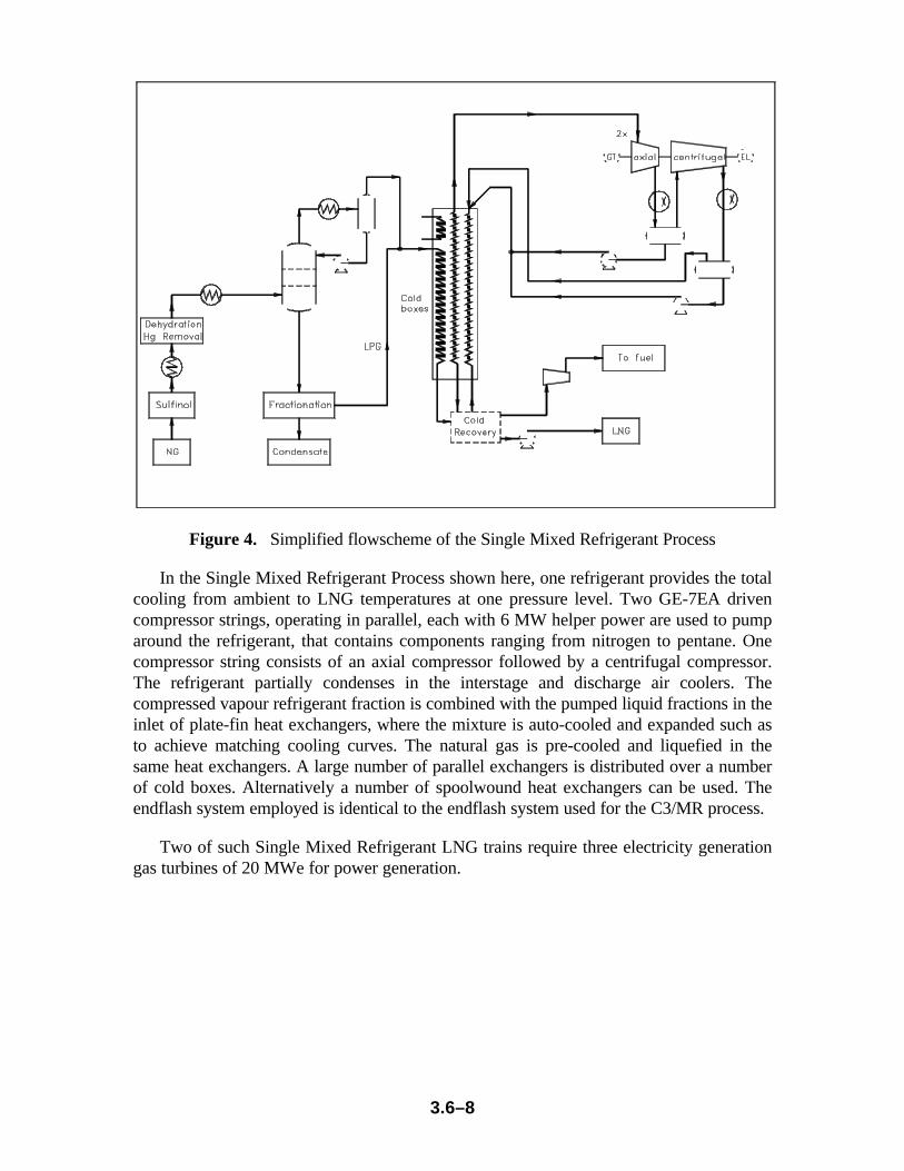
Figure 4. Simplified flowscheme of the Single Mixed Refrigerant Process
In the Single Mixed Refrigerant Process shown here, one refrigerant provides the totalcooling from ambient to LNG temperatures at one pressure level. Two GE-7EA drivencompressor strings, operating in parallel, each with 6 MW helper power are used to pumparound the refrigerant, that contains components ranging from nitrogen to pentane. Onecompressor string consists of an axial compressor followed by a centrifugal compressor.The refrigerant partially condenses in the interstage and discharge air coolers. Thecompressed vapour refrigerant fraction is combined with the pumped liquid fractions in theinlet of plate-fin heat exchangers, where the mixture is auto-cooled and expanded such asto achieve matching cooling curves. The natural gas is pre-cooled and liquefied in thesame heat exchangers. A large number of parallel exchangers is distributed over a numberof cold boxes. Alternatively a number of spoolwound heat exchangers can be used. Theendflash system employed is identical to the endflash system used for the C3/MR process.
Two of such Single Mixed Refrigerant LNG trains require three electricity generationgas turbines of 20 MWe for power generation.

3.6–9
Figure 5. Simplified flowscheme of the Nitrogen Expansion process
The Nitrogen Expansion process uses Propane as precooling medium and Nitrogen asliquefaction refrigerant. A GE-7EA driven axial compressor pumps around Nitrogen thatis pre-cooled against propane. The nitrogen is subsequently auto-cooled and expanded viathree turbo-expander sets, such as to achieve a good match of the cooling curves in thecryogenic heat exchangers. A plate-fin type was selected here, but a spoolwound heatexchanger could have been used as well. A four-stage propane cycle provides theprecooling for the nitrogen and the natural gas. A GE-5C gas turbine to drives thiscompressor with a helper motor. An advanced nitrogen rejection system, identical to theone used for C3/MR is used.
Two of such Nitrogen Expansion LNG trains require a total of three electricitygeneration gas turbines of 20 MWe for power generation.
HARDWARE CONSIDERATIONS
Rotating Equipment
The gas turbines driving the refrigerant compressors are of the heavy industrial type,either the GE-5C (dual shaft, variable speed) or the GE-7EA (single shaft, fixed speed),both from General Electric. These gas turbines have a track record in the LNG industryand have low specific power costs. Each process is optimised such that it utilises as far aspossible the available powers, supplemented by helper motors where economical. Themulti-stage compressors in pre-cooling and in the Cascade process are of the centrifugaltype, in some cases stretched to the maximum flow and head limits. High efficiency axialcompressors are used for the first stage of mixed refrigerant compression and for nitrogen

3.6–10
compression. The selection is based on in-house experience and feedback from rotatingequipment vendors. Electric motors are used as starter/helper and for driving the endflashcompressor. A summary of the rotating equipment used is given in Table 2.
Table 2. Summary of main rotating equipment.
Process C3/MR Cascade DMR SMR N2expansion
PrecoolingGas turbine
GE-7EA (+generator)
2 * GE-5C(+ helper)
GE-7EA (+helper)
N/A GE-5C (+helper)
Precoolingcompressor
4 stagecentrifugal
2 * 3 stagecentrifugal
3 stagecentrifugal
N/A 4 stagecentrifugal
Liquefactiongas turbine
GE-7EA (+helper)
4 * GE-5C GE-7EA (+helper)
2 * GE-7EA(+helper)
GE-7EA (+helper)
Liquefactioncompressor
Axial plus 2stagecentrifugal intandem
Ethylene: 2* 3 stagecentrifugalMethane: 2* 4 stagecentrifugal, 3casings
Axial plus 2stagecentrifugalin tandem
2 * Axialplus singlestagecentrifugalin tandem.
AxialNitrogencompressor;Threeexpander/compressorsets
Heat Exchangers
The cryogenic heat exchangers are of the aluminium spoolwound design, plate-fin orcore-in-kettle type, the selection being based on operating experience, coolingcharacteristics and feedback (including sizes and costs) from vendors. A summary of thecryogenic heat exchanger selection is found in Table 2.
Table 3. Summary of main cryogenic heat exchange equipment
Process C3/MR Cascade DMR SMR N2expansion
Precoolingexchangers
Kettle Core-in-kettle
Spoolwound Plate-Fin Kettle
Liquefactionexchangers
Spoolwound Core-in-kettle/ Plate-Fin
Spoolwound Plate-Fin Plate-Fin
Table 4 below summarises the minimum number of 20 MW turbo-generators requiredfor the different process options (excluding sparing)

3.6–11
Table 4. Summary of electricity generation requirements
Process C3/MR cascade DMR SMR N2expansion
Number of 20 MWturbo-generators
2 3 3 3 3
PROCESS COMPARISON
LNG Production
The process calculations were aimed at maximisation of LNG production within a setof equipment constraints such as available gas turbine power, approach temperatures onair coolers, maximum spoolwound heat exchanger size, etc.
Optimisation of the five processes resulted in the LNG production figures shown inTable 5.
Table 5. Daily LNG production for the five processes(per LNG train, in t/d, excluding process margin)
Process C3/MR Cascade DMR SMR N2expansion
LNG production 11900 10000 13100 11300 6540
The processes have production rates within the target range with the exception of thenitrogen expansion process. The low production of this process is due to the low coldpotential of expanded nitrogen (sensitive heat rather than latent heat) and the lowerpowers installed.
Specific Power
A crude yardstick for cost and efficiency comparison is the specific power of aprocess. This is the ratio of total compressor shaft power absorbed (including allrefrigerant compressors and the endflash compressor, excluding contributions from liquidor gas expanders) over the LNG rundown in t/d. The result is shown in Table 6.
Table 6. Specific power of the five processes.
Process C3/MR Cascade DMR SMR N2expansion
Specific power(kW/(t/d LNGrundown))
12.2 14.1 12.5 14.5 15.6
Inspection of table 6 shows that the C3/MR and the DMR process have comparablelow specific powers, indicating a high degree of optimisation for an air cooled process.

3.6–12
The Cascade process appears to suffer disproportionally from the high ambient coolingtemperatures. It proved to be possible to fully load all gas turbines, albeit that the propanecompressor drivers had to be equipped with sizeable helper motors. Due to the nature ofthe process no liquid expanders can be used in the LNG and refrigerant streams to boostproduction. Furthermore the smaller compressors in the Cascade process tend to havelower efficiencies than the large centrifugal and axial machines in the C3/MR and DMRprocess.
It is also noted that the Cascade process, employing pure components, afteroptimisation for one point of operation, contains no longer any degree of freedom, exceptthe speed of the gas turbines. On the other hand, the C3/MR, DMR, and also the SMRprocess do contain process variables that enable optimisation of process performanceoutside the exact design point.
The SMR specific power of 14.5 kW/t/d, albeit high as compared to C3/MR, is a goodachievement for such a single pressure process.
Train Efficiency
Each liquefaction train provides for its own fuel, mainly endflash gas, and a proportionof the fuel required in the utility area.
The Train efficiency of the processes is defined as the total HHV of valuable products(LNG and condensate) divided by the total HHV of the feed; hence this covers bothprocess efficiency and the efficiency of the gas turbines. It is hereby assumed that wasteheat of the gas turbines is only used for providing process heat and not for steam/powergeneration. Such a kind of combined cycle operation would improve total efficienciesfurther, if this can be justified. The train efficiencies of the liquefaction processes areshown below in Table 7.
Table 7. Train efficiencies of the LNG processes
Process C3/MR Cascade DMR SMR N2expansion
Fuel efficiency (%) 92.9 91.2 92.7 91.6 90.4
Table 7 clearly shows the high train efficiency of the DMR, C3/MR and the SMRprocesses. This is not surprising since these processes use large drivers with a relativelyhigh fuel efficiency of some 31 %. The Cascade process uses gas turbines with a lowerfuel efficiency (25 %). This process has 6 gas turbines and therefore does not lend itselfvery well for full waste heat recovery, should this be required. The Nitrogen expansionprocess has the lowest fuel efficiency, mainly due to the low process efficiency.
Plant Capex
Detailed cost estimates were prepared for two complete liquefaction trains andassociated common utilities, using vendor quotes where applicable. The results arepresented in Table 8 below in an indexed format to exclude local cost factors, C3/MRbeing indexed to 100 %.

3.6–13
Table 8. Indexed Capex comparison
Process C3/MR Cascade DMR SMR N2expansion
Indexed Capex 100 119 116 97 95
The Cascade process is more expensive because of the paralleling of the refrigerantcycles and the large number of equipment items required. Each liquefaction unit has 6refrigerant compressors with a total of 20 pressure stages, etc. Variable speed drives aremandatory for the air cooled process to sustain a minimum degree of operability. Atpresent, variable speed gas turbines of the heavy industrial or aircraft derivative type, arelimited to some 20-25 MW site rating. Larger new machines like the GE LM6000 and theRR Trent 800 (35-45 MW range) offer prospects for a simpler line-up, albeit that thesegas turbines must yet be proven for mechanical drive applications.
The costs of the DMR process appear high as compared to the C3/MR and the SMRprocess. This can be attributed largely to the high costs assumed for the three spoolwoundheat exchangers in the DMR LNG train.
Plant Availability/Annual Capacity
To arrive at annual production volumes the availability of the different processesshould be taken into account. As a first approximation it is assumed that the feed gas isalways available and that there are no restrictions in LNG storage and shipping. Withinthis limited scope, the plant availability was broken down in scheduled unavailability(maintenance, inspections, gas turbine overhauls, etc.), and unscheduled unavailability(equipment failure, nuisance trips, operational mistakes, etc.). The scheduled unavail-ability was averaged over a six years maintenance cycle, dictated by gas turbine majoroverhauls. Differences are small here because all processes employ industrial type gasturbines. For the unscheduled unavailability differences in robustness between spool-wound heat exchangers and plate-fin heat exchangers were addressed as well.
The average annual stream day numbers and annual productions are summarised inTable 9 below.
Table 9. Plant Availability and annual Capacity - 2 LNG trains
Process C3/MR Cascade DMR SMR N2expansion
Plant availability(sd/a)
340 336 340 338 335
Annualproduction(MTPA)
7.9 6.6 8.7 7.4 4.3
N.B: The annual production includes a 2.5 % process margin.
3.6–14
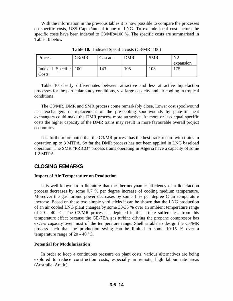
With the information in the previous tables it is now possible to compare the processeson specific costs, US$ Capex/annual tonne of LNG. To exclude local cost factors thespecific costs have been indexed to C3/MR=100 %. The specific costs are summarised inTable 10 below.
Table 10. Indexed Specific costs (C3/MR=100)
Process C3/MR Cascade DMR SMR N2expansion
Indexed SpecificCosts
100 143 105 103 175
Table 10 clearly differentiates between attractive and less attractive liquefactionprocesses for the particular study conditions, viz. large capacity and air cooling in tropicalconditions
The C3/MR, DMR and SMR process come remarkably close. Lower cost spoolwoundheat exchangers or replacement of the pre-cooling spoolwounds by plate-fin heatexchangers could make the DMR process more attractive. At more or less equal specificcosts the higher capacity of the DMR trains may result in more favourable overall projecteconomics.
It is furthermore noted that the C3/MR process has the best track record with trains inoperation up to 3 MTPA. So far the DMR process has not been applied in LNG baseloadoperation. The SMR “PRICO” process trains operating in Algeria have a capacity of some1.2 MTPA.
CLOSING REMARKS
Impact of Air Temperature on Production
It is well known from literature that the thermodynamic efficiency of a liquefactionprocess decreases by some 0.7 % per degree increase of cooling medium temperature.Moreover the gas turbine power decreases by some 1 % per degree C air temperatureincrease. Based on these two simple yard sticks it can be shown that the LNG productionof an air cooled LNG plant changes by some 30-35 % over an ambient temperature rangeof 20 - 40 °C. The C3/MR process as depicted in this article suffers less from thistemperature effect because the GE-7EA gas turbine driving the propane compressor hasexcess capacity over most of the temperature range. Shell is able to design the C3/MRprocess such that the production swing can be limited to some 10-15 % over atemperature range of 20 - 40 °C.
Potential for Modularisation
In order to keep a continuous pressure on plant costs, various alternatives are beingexplored to reduce construction costs, especially in remote, high labour rate areas(Australia, Arctic).

3.6–15
Modularised construction of the LNG plant is one of these ideas. The concept is todivide the process and utility units in large self-supported modules (say 1000 tonnes permodule) and to fabricate these in an area with relatively high productivity and low labourrates. The modules are subsequently shipped to the plant site and welded together.
Another idea is to build an entire LNG train on a concrete gravity structure (CGS) andto transport this to an inshore location near the gas supply. Water cooling would then bethe logical choice as ambient cooling medium. BHP goes as far as proposing an entireLNG plant on an offshore GCS. Since chilled water is used for pre-cooling the Nitrogencycle, the hydrocarbon inventory in the entire process is at a minimum. This concept isoutside the scope of this comparison study.
All processes studied can be modularised in this way, albeit that cost savings are moremodest than generally assumed. The extra costs for pre-ordering, early detailedengineering, extra structural steel, transport, etc., offset to a large extent the savings ingoing to lower cost construction yards.
The two processes that seem most suitable for modularised construction are the SMRprocess and the Nitrogen expansion process. The SMR process combines a rather highLNG production with a minimum of equipment. To a lesser extent (moreexpander/compressors, etc.) the same applies for the Nitrogen expansion process. Theother processes have either a lot of equipment needing more modules or less equipmentbut with considerable height that cannot be transported vertically (spoolwound heatexchangers). These equipment items can be pre-fabricated, i.e. dressed up with platforms,etc., to reduce local construction.
CONCLUSIONS
The Propane/MR process appears to be the best choice within the premises of thiscomparison study, viz. large capacity LNG trains, employing air cooling in a tropicalclimate. Other promising processes are the Dual Mixed Refrigerant process and the SingleMixed refrigerant process. Shell is further investigating several variations of these threeprocesses.
The Cascade process appears to be relatively expensive, partly disadvantaged as it isby the study premises. Under colder conditions (arctic, water cooling) the capacity comescloser to the C3/MR capacity.
The pre-cooled Nitrogen Expansion process is not an economic choice for a large,onshore application. It may be an alternative for smaller scale offshore applications(absence of hydrocarbon refrigerants).