Comparison between FEBio and Abaqus for biphasic …eprints.whiterose.ac.uk/76912/1/Meng_IMECHE_Part...
13
This is a repository copy of Comparison between FEBio and Abaqus for biphasic contact problems.. White Rose Research Online URL for this paper: http://eprints.whiterose.ac.uk/76912/ Article: Meng, Q, Jin, Z, Fisher, J et al. (1 more author) (2013) Comparison between FEBio and Abaqus for biphasic contact problems. Proceedings of the Institution of Mechanical Engineers, Part H: Journal of Engineering in Medicine, 227 (9). 1009 - 1019. ISSN 0954-4119 https://doi.org/10.1177/0954411913483537 [email protected] https://eprints.whiterose.ac.uk/ Reuse Unless indicated otherwise, fulltext items are protected by copyright with all rights reserved. The copyright exception in section 29 of the Copyright, Designs and Patents Act 1988 allows the making of a single copy solely for the purpose of non-commercial research or private study within the limits of fair dealing. The publisher or other rights-holder may allow further reproduction and re-use of this version - refer to the White Rose Research Online record for this item. Where records identify the publisher as the copyright holder, users can verify any specific terms of use on the publisher’s website. Takedown If you consider content in White Rose Research Online to be in breach of UK law, please notify us by emailing [email protected] including the URL of the record and the reason for the withdrawal request.
Transcript of Comparison between FEBio and Abaqus for biphasic …eprints.whiterose.ac.uk/76912/1/Meng_IMECHE_Part...

This is a repository copy of Comparison between FEBio and Abaqus for biphasic contact problems..
White Rose Research Online URL for this paper:http://eprints.whiterose.ac.uk/76912/
Article:
Meng, Q, Jin, Z, Fisher, J et al. (1 more author) (2013) Comparison between FEBio and Abaqus for biphasic contact problems. Proceedings of the Institution of Mechanical Engineers, Part H: Journal of Engineering in Medicine, 227 (9). 1009 - 1019. ISSN 0954-4119
https://doi.org/10.1177/0954411913483537
[email protected]://eprints.whiterose.ac.uk/
Reuse
Unless indicated otherwise, fulltext items are protected by copyright with all rights reserved. The copyright exception in section 29 of the Copyright, Designs and Patents Act 1988 allows the making of a single copy solely for the purpose of non-commercial research or private study within the limits of fair dealing. The publisher or other rights-holder may allow further reproduction and re-use of this version - refer to the White Rose Research Online record for this item. Where records identify the publisher as the copyright holder, users can verify any specific terms of use on the publisher’s website.
Takedown
If you consider content in White Rose Research Online to be in breach of UK law, please notify us by emailing [email protected] including the URL of the record and the reason for the withdrawal request.

http://pih.sagepub.com/Medicine
Engineers, Part H: Journal of Engineering in Proceedings of the Institution of Mechanical
http://pih.sagepub.com/content/227/9/1009The online version of this article can be found at:
DOI: 10.1177/0954411913483537
originally published online 26 June 2013 2013 227: 1009Proceedings of the Institution of Mechanical Engineers, Part H: Journal of Engineering in Medicine
Qingen Meng, Zhongmin Jin, John Fisher and Ruth WilcoxComparison between FEBio and Abaqus for biphasic contact problems
Published by:
http://www.sagepublications.com
On behalf of:
Institution of Mechanical Engineers
can be found at:Proceedings of the Institution of Mechanical Engineers, Part H: Journal of Engineering in MedicineAdditional services and information for
Immediate free access via SAGE ChoiceOpen Access:
http://pih.sagepub.com/cgi/alertsEmail Alerts:
http://pih.sagepub.com/subscriptionsSubscriptions:
http://www.sagepub.com/journalsReprints.navReprints:
http://www.sagepub.com/journalsPermissions.navPermissions:
http://pih.sagepub.com/content/227/9/1009.refs.htmlCitations:
What is This?
- Jun 26, 2013OnlineFirst Version of Record
- Aug 9, 2013Version of Record >>
at University of Leeds on November 1, 2013pih.sagepub.comDownloaded from at University of Leeds on November 1, 2013pih.sagepub.comDownloaded from at University of Leeds on November 1, 2013pih.sagepub.comDownloaded from at University of Leeds on November 1, 2013pih.sagepub.comDownloaded from at University of Leeds on November 1, 2013pih.sagepub.comDownloaded from at University of Leeds on November 1, 2013pih.sagepub.comDownloaded from at University of Leeds on November 1, 2013pih.sagepub.comDownloaded from at University of Leeds on November 1, 2013pih.sagepub.comDownloaded from at University of Leeds on November 1, 2013pih.sagepub.comDownloaded from at University of Leeds on November 1, 2013pih.sagepub.comDownloaded from at University of Leeds on November 1, 2013pih.sagepub.comDownloaded from at University of Leeds on November 1, 2013pih.sagepub.comDownloaded from

Original Article
Proc IMechE Part H:
J Engineering in Medicine
227(9) 1009–1019
� IMechE 2013
Reprints and permissions:
sagepub.co.uk/journalsPermissions.nav
DOI: 10.1177/0954411913483537
pih.sagepub.com
Comparison between FEBio andAbaqus for biphasic contact problems
Qingen Meng1, Zhongmin Jin1,2, John Fisher1 and Ruth Wilcox1
Abstract
Articular cartilage plays an important role in the function of diarthrodial joints. Computational methods have been used
to study the biphasic mechanics of cartilage, and Abaqus has been one of the most widely used commercial software
packages for this purpose. A newly developed open-source finite element solver, FEBio, has been developed specificallyfor biomechanical applications. The aim of this study was to undertake a direct comparison between FEBio and Abaqus
for some practical contact problems involving cartilage. Three model types, representing a porous flat-ended indentation
test, a spherical-ended indentation test, and a conceptual natural joint contact model, were compared. In addition, aparameter sensitivity study was also performed for the spherical-ended indentation test to investigate the effects of
changes in the input material properties on the model outputs, using both FEBio and Abaqus. Excellent agreement was
found between FEBio and Abaqus for all of the model types and across the range of material properties that wereinvestigated.
Keywords
Articular cartilage, biphasic model, finite element, Abaqus, FEBio
Date received: 15 October 2012; accepted: 28 February 2013
Introduction
Articular cartilage (AC) plays an important role in the
function of diarthrodial joints. It helps to distribute the
loads between opposing bones over a large contact area
and minimize the contact stress. The biphasic nature of
AC and in particular load carriage by the fluid phase
provides a bearing surface with low friction and wear
over a life span. It is important to understand the
mechanical behavior of cartilage in order to develop
effective treatments for damaged or diseased joints. It
is generally accepted that for a correct description of
the mechanical behavior of AC, at least a biphasic
model1 should be used. Analytical solutions can be
found for only a limited number of idealized biphasic
problems, such as confined and unconfined compres-
sion tests. For problems with complex geometry and
under realistic conditions, it is necessary to use numeri-
cal approximation techniques, such as the finite ele-
ment method.
Abaqus (Dassault Systemes, Waltham, MA, USA) is
a commonly used commercial finite element program.
Finite element models that include cartilage compo-
nents can be solved using the soil consolidation theory
within Abaqus, and it has been one of the most widely
used programs to study the biphasic mechanics of
cartilage since the 1990s. Studies that employ Abaqus
have been extended from those that evaluate its feasibil-
ity to analyze biphasic soft tissues2,3 to practical appli-
cations where cartilage is simulated within a realistic
problem.4–9 Recently, a freely available, open-source
nonlinear finite element solver, FEBio (Musculoskeletal
Research Laboratories, University of Utah, Salt Lake
City, UT, USA), was developed specifically for biome-
chanical applications.10,11 Porous media problems, such
as the biphasic mechanics of cartilage, can be solved by
FEBio using the biphasic material model embedded
within the code. A finite element contact implementa-
tion for biphasic materials is available in the code. This
implementation is able to accommodate finite deforma-
tion and large sliding.11
The comparison between different codes is impor-
tant for verification, especially for practical problems
1Institute of Medical and Biological Engineering, School of Mechanical
Engineering, University of Leeds, Leeds, UK2School of Mechanical Engineering, Xi’an Jiaotong University, Xi’an, China
Corresponding author:
Qingen Meng, Institute of Medical and Biological Engineering, School of
Mechanical Engineering, University of Leeds, Leeds, LS2 9JT, UK.
Email: [email protected]; [email protected]
where no analytical solutions exist. In biomechanical
analyses, it is common practice to compare the solu-
tions of the same problem produced by different codes,
especially for newly developed software or new applica-
tions of existing algorithms. Previously, comparisons
have been made between other software packages for a
confined compression problem to examine the feasibil-
ity of available soil mechanic codes to analyze biphasic
tissue mechanics.12 Comparisons have also been
made between the commercial package COMSOL
Multiphysics (COMSOL, Inc., Burlington, MA, USA)
and previous codes to validate the implementation of
augmented Lagrangian method in COMSOL
Multiphysics.13 The direct comparison between Abaqus
and FEBio is particularly important since FEBio has
been developed recently, and Abaqus is one of the most
established finite element packages in the field. A wide
range of comparative tests have been undertaken to
examine the performance of FEBio relative to Abaqus
for different material models, geometry, and condi-
tions.10 However, no biphasic problems have been
included in these comparisons. Therefore, the aim of
this study was to undertake a direct comparison
between FEBio and Abaqus for three practical biphasic
problems involving cartilage.
Methods
Three cartilage models were solved using both Abaqus
(Version 6.9-EF1) and FEBio (Version 1.5.0). The first
two represented standard experimental characterization
procedures using a porous flat-ended indentation test
and a solid spherical-ended indentation test. The third
represented contact between two conforming cartilage
surfaces as is present in the diarthrodial joints. Since
both displacement and load controls are commonly
employed in such problems, displacement control was
used in the porous flat-ended indentation test and load
control was applied to the spherical-ended indentation
test.
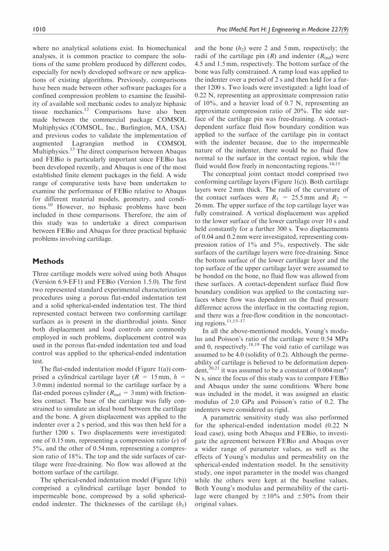
The flat-ended indentation model (Figure 1(a)) com-
prised a cylindrical cartilage layer (R = 15mm, h =
3.0mm) indented normal to the cartilage surface by a
flat-ended porous cylinder (Rind = 3mm) with friction-
less contact. The base of the cartilage was fully con-
strained to simulate an ideal bond between the cartilage
and the bone. A given displacement was applied to the
indenter over a 2 s period, and this was then held for a
further 1200 s. Two displacements were investigated:
one of 0.15mm, representing a compression ratio (e) of
5%, and the other of 0.54mm, representing a compres-
sion ratio of 18%. The top and the side surfaces of car-
tilage were free-draining. No flow was allowed at the
bottom surface of the cartilage.
The spherical-ended indentation model (Figure 1(b))
comprised a cylindrical cartilage layer bonded to
impermeable bone, compressed by a solid spherical-
ended indenter. The thicknesses of the cartilage (h1)
and the bone (h2) were 2 and 5mm, respectively; the
radii of the cartilage pin (R) and indenter (Rind) were
4.5 and 1.5mm, respectively. The bottom surface of the
bone was fully constrained. A ramp load was applied to
the indenter over a period of 2 s and then held for a fur-
ther 1200 s. Two loads were investigated: a light load of
0.22 N, representing an approximate compression ratio
of 10%, and a heavier load of 0.7 N, representing an
approximate compression ratio of 20%. The side sur-
face of the cartilage pin was free-draining. A contact-
dependent surface fluid flow boundary condition was
applied to the surface of the cartilage pin in contact
with the indenter because, due to the impermeable
nature of the indenter, there would be no fluid flow
normal to the surface in the contact region, while the
fluid would flow freely in noncontacting regions.14,15
The conceptual joint contact model comprised two
conforming cartilage layers (Figure 1(c)). Both cartilage
layers were 2mm thick. The radii of the curvature of
the contact surfaces were R1 = 25.5mm and R2 =
26mm. The upper surface of the top cartilage layer was
fully constrained. A vertical displacement was applied
to the lower surface of the lower cartilage over 10 s and
held constantly for a further 300 s. Two displacements
of 0.04 and 0.2mm were investigated, representing com-
pression ratios of 1% and 5%, respectively. The side
surfaces of the cartilage layers were free-draining. Since
the bottom surface of the lower cartilage layer and the
top surface of the upper cartilage layer were assumed to
be bonded on the bone, no fluid flow was allowed from
these surfaces. A contact-dependent surface fluid flow
boundary condition was applied to the contacting sur-
faces where flow was dependent on the fluid pressure
difference across the interface in the contacting region,
and there was a free-flow condition in the noncontact-
ing regions.11,15–17
In all the above-mentioned models, Young’s modu-
lus and Poisson’s ratio of the cartilage were 0.54 MPa
and 0, respectively.18,19 The void ratio of cartilage was
assumed to be 4.0 (solidity of 0.2). Although the perme-
ability of cartilage is believed to be deformation depen-
dent,20,21 it was assumed to be a constant of 0.004mm4/
N s, since the focus of this study was to compare FEBio
and Abaqus under the same conditions. Where bone
was included in the model, it was assigned an elastic
modulus of 2.0 GPa and Poisson’s ratio of 0.2. The
indenters were considered as rigid.
A parametric sensitivity study was also performed
for the spherical-ended indentation model (0.22 N
load case), using both Abaqus and FEBio, to investi-
gate the agreement between FEBio and Abaqus over
a wider range of parameter values, as well as the
effects of Young’s modulus and permeability on the
spherical-ended indentation model. In the sensitivity
study, one input parameter in the model was changed
while the others were kept at the baseline values.
Both Young’s modulus and permeability of the carti-
lage were changed by 610% and 650% from their
original values.
1010 Proc IMechE Part H: J Engineering in Medicine 227(9)
Since all the problems considered in this study were
axisymmetric, for computational efficiency and to
avoid the convergence difficulties of solving three-
dimensional (3D) biphasic models in Abaqus, axisym-
metric models were developed and solved in Abaqus.
In FEBio, where there was no axisymmetric stress state
option in Version 1.5.0, a quarter of each model was
solved by applying appropriate symmetry boundary
conditions. The mesh densities adopted for each model
were determined after a mesh convergence study. The
changes in the peak fluid pressure caused by doubling
the meshes used in the present study were less than 1%
for all models. The number of elements for the cartilage
in each model is summarized in Table 1.
In the Abaqus models, the cartilage region was dis-
cretized with CAX4P (four-node bilinear displacement
and pore pressure) elements. Where the bone was
included (the spherical-ended indentation model), it
was discretized with CAX4 (four-node bilinear stress/
displacement axisymmetric) elements. The soils, consoli-
dation analysis procedure was used to solve the models.
The cartilage permeability was converted into that
required for the poroelastic model by multiplying it by
the volume weight of the interstitial fluid.3 Automatic
time incrementation was employed for each model by
specifying an appropriate value for UTOL that was less
than 8% of the maximum pore pressure.2 Linear elastic
material was used for the solid phase of the cartilage.
The NLGEOM parameter was used to account for the
finite deformation so that comparisons could be made
with FEBio, which is based on finite deformation
theory.10,11Surface-to-surface contact discretization and
a finite sliding tracking approach were used for all the
models. Therefore, by default, a penalty method was
used as the constraint enforcement method. For all the
models, flow was not permitted across the axis of
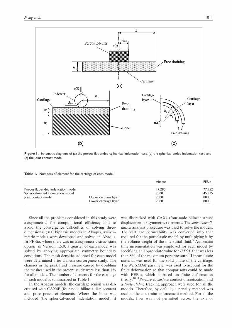
Figure 1. Schematic diagrams of (a) the porous flat-ended cylindrical indentation test, (b) the spherical-ended indentation test, and
(c) the joint contact model.
Table 1. Numbers of element for the cartilage of each model.
Abaqus FEBio
Porous flat-ended indentation model 17,280 77,952Spherical-ended indentation model 2000 45,375Joint contact model Upper cartilage layer 2880 8000
Lower cartilage layer 2880 8000
Meng et al. 1011

symmetry. Free-draining boundary conditions were
specified by giving a zero value to the pore pressure of
the nodes on these surfaces. The contact-dependent
flow boundary conditions were achieved using user-
developed subroutines.15–16 To examine the effect of
the contact-dependency subroutine, the spherical-ended
indentation model and the conceptual joint contact
model were also solved using the default fluid flow
boundary conditions in Abaqus (i.e. by removing the
applied subroutine, such that the enforced relation
between fluid flow and fluid pressure difference at the
contact area and the free-draining outside the contact
region were eliminated).
Before the 3D finite element models were
solved using FEBio, solid models were created and
meshed using Preview 1.7 (Musculoskeletal Research
Laboratories) or NX-IDEAS 6.1 (Siemens Product
Lifecycle Management (PLM) Software Inc., Plano,
TX, USA). Eight-node hexahedral or six-node hexa-
hedral solid elements were used to discretize the mod-
els. Neo-Hookean was used as the solid-phase
material of the cartilage to account for the finite
deformation. It should be noted that prior to this
study, a uniaxial analysis on the elastic materials in
FEBio and Abaqus was performed. The results
showed that under finite deformation, the Neo-
Hookean material in FEBio and the linear elastic
material in Abaqus predicted almost identical stress
values for applied strains up to 20% when the mate-
rial properties used in this study were applied. The
biphasic analysis step was used to solve these biphasic
contact problems. The sliding2 implementation,
which by default uses facet-to-facet discretization and
takes large sliding into account, was defined as the
contact interface. The penalty method was used to
enforce the contact constraints. The auto-penalty was
applied for all models to calculate a suitable initial
value for the penalty factor. Flow was prevented from
the symmetric surfaces of cartilage of each model.
Similar to Abaqus, free-draining boundary conditions
were specified by giving zero pore pressure. The
contact-dependent surface fluid flow boundary condi-
tions were satisfied automatically.11
The average difference, Rv, in the examined variables
was used to estimate the agreement between FEBio and
Abaqus, which was defined as
Rv =1
n
X
n
i=1
vAbaqusi � vFEBioi
�
�
�
�
�
�
vFEBioi
0
@
1
A ð1Þ
where vi is the examined variable, such as reaction
force, fluid pressure, or displacement, at time step i,
and n is the total number of time steps.
Results
For the porous flat-ended indenter model, the predicted
fluid pressure distribution at 2 and 1200 s was found to
be very similar in Abaqus and FEBio, as shown in
Figure 2, although there were some minor local differ-
ences. For both displacements, the reaction force acting
on the indenter and the fluid pressure in the cartilage at
a reference node (under the contact center and at the
Figure 2. Fluid pressure distribution in the cartilage of the porous flat-ended indentation model subjected to a displacement of
0.15mm, at 2 s, obtained by (a) Abaqus and (b) FEBio and for the same model at 1200 s, obtained by (c) Abaqus and (d) FEBio. POR
stands for the pore pressure in Abaqus.
1012 Proc IMechE Part H: J Engineering in Medicine 227(9)
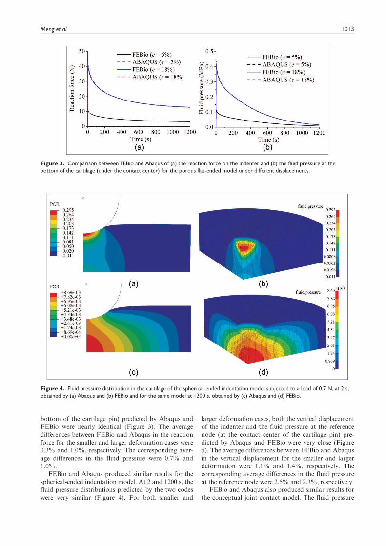
bottom of the cartilage pin) predicted by Abaqus and
FEBio were nearly identical (Figure 3). The average
differences between FEBio and Abaqus in the reaction
force for the smaller and larger deformation cases were
0.3% and 1.0%, respectively. The corresponding aver-
age differences in the fluid pressure were 0.7% and
1.0%.
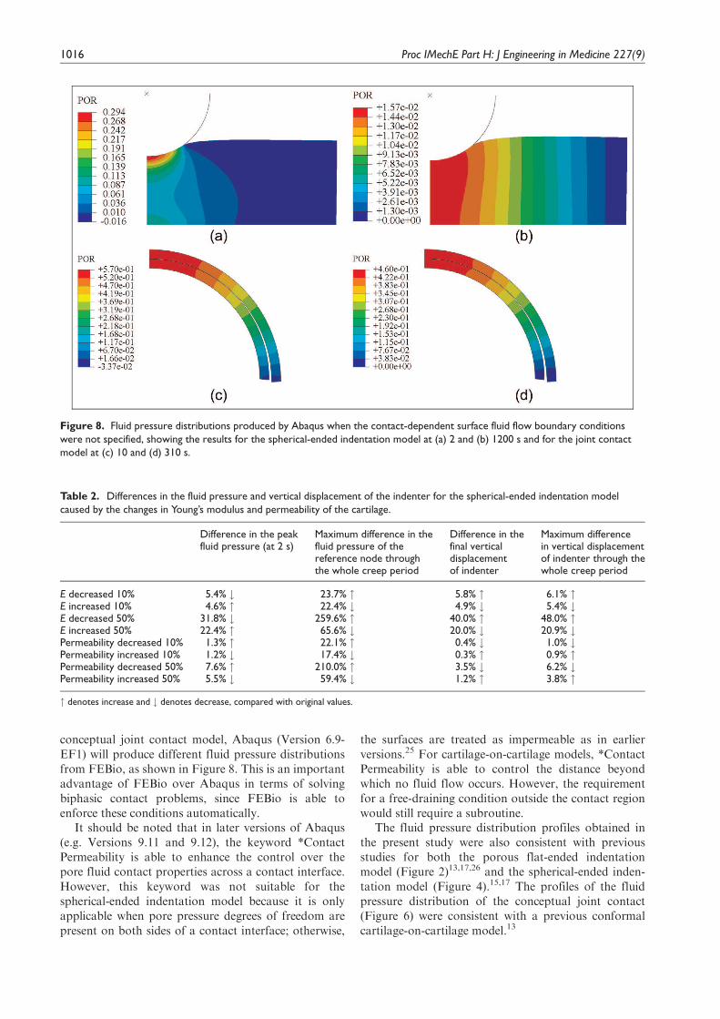
FEBio and Abaqus produced similar results for the
spherical-ended indentation model. At 2 and 1200 s, the
fluid pressure distributions predicted by the two codes
were very similar (Figure 4). For both smaller and
larger deformation cases, both the vertical displacement
of the indenter and the fluid pressure at the reference
node (at the contact center of the cartilage pin) pre-
dicted by Abaqus and FEBio were very close (Figure
5). The average differences between FEBio and Abaqus
in the vertical displacement for the smaller and larger
deformation were 1.1% and 1.4%, respectively. The
corresponding average differences in the fluid pressure
at the reference node were 2.5% and 2.3%, respectively.
FEBio and Abaqus also produced similar results for
the conceptual joint contact model. The fluid pressure
Figure 3. Comparison between FEBio and Abaqus of (a) the reaction force on the indenter and (b) the fluid pressure at the
bottom of the cartilage (under the contact center) for the porous flat-ended model under different displacements.
Figure 4. Fluid pressure distribution in the cartilage of the spherical-ended indentation model subjected to a load of 0.7 N, at 2 s,
obtained by (a) Abaqus and (b) FEBio and for the same model at 1200 s, obtained by (c) Abaqus and (d) FEBio.
Meng et al. 1013

distributions predicted by FEBio and Abaqus closely
matched at both 10 and 300 s (Figure 6). For both the
0.04 and 0.2mm displacement cases, the fluid pressure
and the contact pressure at the reference node (at the
contact center) predicted by Abaqus and FEBio were
very similar (Figure 7). The average differences in fluid
pressure between FEBio and Abaqus for cases of e =
1% and 5% were 2.0% and 5.4%, respectively. The
corresponding average differences in the contact pres-
sure were 7.0% and 7.6%, respectively.
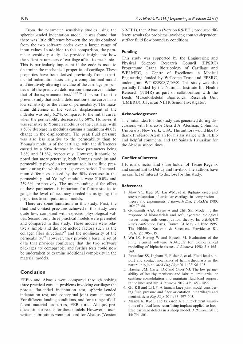
The fluid pressure distributions of the models solved
using Abaqus with the default fluid flow boundary con-
ditions (i.e. without specifying the contact-dependent
surface fluid flow boundary conditions using subrou-
tines) are shown in Figure 8. Notably, fluid pressuriza-
tion was seen to occur at noncontacting areas. The fluid
pressure distribution of the spherical-ended indentation
model at 1200 s was clearly different from those shown
in Figure 4(c) and (d). The fluid pressure distributions
of the joint contact model at 10 and 310 s were also dif-
ferent from those shown in Figure 6.
For the wide range of material properties investi-
gated for the spherical-ended indentation model, FEBio
and Abaqus agreed well (Figures 9 and 10). The maxi-
mum average differences between Abaqus and FEBio
in the fluid pressure for the cases presented in Figures 9
and 10 were 3.1%, and the maximum average differ-
ences in the vertical displacement were 1.4%. The varia-
tion in Young’s modulus of the cartilage had three
notable effects on its mechanical behavior. A smaller
Young’s modulus reduced the peak fluid pressure, pro-
longed the time to approach the equilibrium condition,
and produced a larger equilibrium deformation (Figure
9). The model predictions were less sensitive to the var-
iation in the permeability of the cartilage. A smaller
permeability slightly increased the peak fluid pressure
and took longer time to reduce the fluid pressure to
zero (Figure 10). The differences in the peak fluid pres-
sure (at 2 s) and the final vertical displacement, along
with the maximum differences in the fluid pressure of
the reference node (at the contact center of the cartilage
pin) and the displacement of the indenter during the
whole creep process, caused by all the investigated
changes in Young’s modulus and permeability of carti-
lage, are summarized in Table 2. In all cases, the 50%
decrease in Young’s modulus and the 50% decrease in
the permeability caused the maximum differences in the
four criteria, as shown in Table 2.
Discussion
Abaqus is a commonly used software package. Biphasic
models are solved in Abaqus using the soil consolida-
tion theory.2,21 FEBio is based on biphasic theory that
is derived from mixture theory of porous media.10
When the solid and fluid phases are assumed intrinsi-
cally incompressible, the fluid is assumed as inviscid
and the inertial effects are neglected, as considered for
cartilage, and the soil consolidation theory and biphasic
theory are equivalent.22,23 They are therefore expected
to produce similar solutions for the same biphasic prob-
lem. However, few direct comparisons have been per-
formed for cartilage biphasic problems in the literature,
particularly for practical applications or more complex
geometry. The present study provided evidence for this
theoretical agreement by solving the same models using
both FEBio and Abaqus.
In the present study, three practical biphasic models,
the porous flat-ended indentation test, the spherical-
ended indentation test, and the cartilage-on-cartilage
model, were compared under different levels of defor-
mation. Moreover, a wide range of material properties
was also considered for the spherical-ended indentation
test. For all the cases investigated, FEBio and Abaqus
produced similar solutions (Figures 2–7, 9, and 10).
It should be noted that there are also some differ-
ences in the contact interface methods employed by the
two software packages. For example, for the rigid-on-
cartilage models, if the contact-dependent surface fluid
flow boundary conditions are not specified in Abaqus
Figure 5. Comparison between FEBio and Abaqus of (a) the displacement of the indenter and (b) the fluid pressure at the contact
center for the spherical-ended model under different forces.
1014 Proc IMechE Part H: J Engineering in Medicine 227(9)

(Version 6.9-EF1) models, the contacting surface of
cartilage is sealed by default.21,24 For cartilage-on-
cartilage models, in the transient analysis of Abaqus
(Version 6.9-EF1), by default, the fluid flowing into the
interface is balanced with the rate of separation of the
two surfaces (i.e. fluid also flows into the contacting
surfaces at the noncontacting regions).21 Therefore, if
the contact-dependent surface fluid flow boundary con-
ditions were not satisfied using user-written subroutines
for the spherical-ended indentation model and the
Figure 6. Fluid pressure distribution for the joint contact model subjected to displacement of 0.04mm, at 10 s, obtained by (a)
Abaqus and (b) FEBio and for the same model, at 310 s, obtained by (c) Abaqus and (d) FEBio.
Figure 7. Comparison between FEBio and Abaqus of (a) the fluid pressure and (b) the contact pressure at the contact center of
the joint contact model under different displacements.
Meng et al. 1015
conceptual joint contact model, Abaqus (Version 6.9-
EF1) will produce different fluid pressure distributions
from FEBio, as shown in Figure 8. This is an important
advantage of FEBio over Abaqus in terms of solving
biphasic contact problems, since FEBio is able to
enforce these conditions automatically.
It should be noted that in later versions of Abaqus
(e.g. Versions 9.11 and 9.12), the keyword *Contact
Permeability is able to enhance the control over the
pore fluid contact properties across a contact interface.
However, this keyword was not suitable for the
spherical-ended indentation model because it is only
applicable when pore pressure degrees of freedom are
present on both sides of a contact interface; otherwise,
the surfaces are treated as impermeable as in earlier
versions.25 For cartilage-on-cartilage models, *Contact
Permeability is able to control the distance beyond
which no fluid flow occurs. However, the requirement
for a free-draining condition outside the contact region
would still require a subroutine.
The fluid pressure distribution profiles obtained in
the present study were also consistent with previous
studies for both the porous flat-ended indentation
model (Figure 2)13,17,26 and the spherical-ended inden-
tation model (Figure 4).15,17 The profiles of the fluid
pressure distribution of the conceptual joint contact
(Figure 6) were consistent with a previous conformal
cartilage-on-cartilage model.13
Figure 8. Fluid pressure distributions produced by Abaqus when the contact-dependent surface fluid flow boundary conditions
were not specified, showing the results for the spherical-ended indentation model at (a) 2 and (b) 1200 s and for the joint contact
model at (c) 10 and (d) 310 s.
Table 2. Differences in the fluid pressure and vertical displacement of the indenter for the spherical-ended indentation model
caused by the changes in Young’s modulus and permeability of the cartilage.
Difference in the peakfluid pressure (at 2 s)
Maximum difference in thefluid pressure of thereference node throughthe whole creep period
Difference in thefinal verticaldisplacementof indenter
Maximum differencein vertical displacementof indenter through thewhole creep period
E decreased 10% 5.4% # 23.7% " 5.8% " 6.1% "E increased 10% 4.6% " 22.4% # 4.9% # 5.4% #E decreased 50% 31.8% # 259.6% " 40.0% " 48.0% "E increased 50% 22.4% " 65.6% # 20.0% # 20.9% #Permeability decreased 10% 1.3% " 22.1% " 0.4% # 1.0% #Permeability increased 10% 1.2% # 17.4% # 0.3% " 0.9% "Permeability decreased 50% 7.6% " 210.0% " 3.5% # 6.2% #Permeability increased 50% 5.5% # 59.4% # 1.2% " 3.8% "
" denotes increase and # denotes decrease, compared with original values.
1016 Proc IMechE Part H: J Engineering in Medicine 227(9)

Figure 9. Effect of changes in the elastic modulus of the cartilage on (a, b) the fluid pressure and (c, d) the vertical displacement of
the indenter for the spherical-ended indentation test, calculated by both FEBio and Abaqus.
Figure 10. Effect of changes in the permeability on (a, b) the fluid pressure and (c, d) the vertical displacement of the indenter for
the spherical-ended indentation test, calculated by both FEBio and Abaqus.
Meng et al. 1017
From the parameter sensitivity studies using the
spherical-ended indentation model, it was found that
there was little difference between the results obtained
from the two software codes over a larger range of
input values. In addition to this comparison, the para-
meter sensitivity study also provided insight into how
the salient parameters of cartilage affect its mechanics.
This is particularly important if the code is used to
determine the mechanical properties of cartilage. These
properties have been derived previously from experi-
mental indentation tests using a computational model
and iteratively altering the value of the cartilage proper-
ties until the predicted deformation–time curve matches
that of the experimental test.18,27,26 It is clear from the
present study that such a deformation–time curve has a
low sensitivity to the value of permeability. The maxi-
mum difference in the vertical displacement of the
indenter was only 6.2%, compared to the initial curve,
when the permeability decreased by 50%. However, it
was sensitive to Young’s modulus of the cartilage, with
a 50% decrease in modulus causing a maximum 48.0%
change in the displacement. The peak fluid pressure
was also less sensitive to the permeability than to
Young’s modulus of the cartilage, with the differences
caused by a 50% decrease in these parameters being
7.6% and 31.8%, respectively. However, it should be
noted that more generally, both Young’s modulus and
permeability played an important role in the fluid pres-
sure, during the whole cartilage creep period. The maxi-
mum differences caused by the 50% decrease in the
permeability and Young’s modulus were 210.0% and
259.6%, respectively. The understanding of the effect
of these parameters is important for future studies to
gauge the level of accuracy needed in assigning the
properties to computational models.
There are some limitations in this study. First, the
fluid and contact pressures achieved in this study were
quite low, compared with expected physiological val-
ues. Second, only three practical models were presented
and compared in this study. These models were rela-
tively simple and did not include factors such as the
collagen fiber directions29 and the nonlinearity of the
permeability.19 However, they provide a baseline set of
data that provides confidence that the two software
packages are comparable, and further tests could now
be undertaken to examine additional complexity in the
material models.
Conclusion
FEBio and Abaqus were compared through solving
three practical contact problems involving cartilage: the
porous flat-ended indentation test, spherical-ended
indentation test, and conceptual joint contact model.
For different loading conditions, and for a range of dif-
ferent material properties, FEBio and Abaqus pro-
duced similar results for these models. However, if user-
written subroutines were not used for Abaqus (Version
6.9-EF1), then Abaqus (Version 6.9-EF1) produced dif-
ferent results for problems involving contact-dependent
surface fluid flow boundary conditions.
Funding
This study was supported by the Engineering and
Physical Sciences Research Council (EPSRC)
Programme Grant Biotribology of Cartilage and
WELMEC, a Centre of Excellence in Medical
Engineering funded by Wellcome Trust and EPSRC,
under grant WT 088908/Z/09/Z. This study was also
partially funded by the National Institute for Health
Research (NIHR) as part of collaboration with the
Leeds Musculoskeletal Biomedical Research Unit
(LMBRU). J.F. is an NIHR Senior Investigator.
Acknowledgement
The initial idea for this study was generated during dis-
cussions with Professor Gerard A. Ateshian, Columbia
University, New York, USA. The authors would like to
thank Professor Ateshian for his assistance with FEBio
and helpful comments and Dr Sainath Pawaskar for
the Abaqus subroutines.
Conflict of Interest
J.F. is a director and share holder of Tissue Regenix
and consultant to DePuy and Invibio. The authors have
no conflict of interest to disclose for this study.
References
1. Mow VC, Kuei SC, Lai WM, et al. Biphasic creep and
stress relaxation of articular cartilage in compression—
theory and experiments. J Biomech Eng: T ASME 1980;
102: 73–84.
2. Goldsmith AAJ, Hayes A and Clift SE. Modelling the
response of biomaterials and soft, hydrated biological
tissues using soils consolidation theory. In: ABAQUS
user’s conference, Paris, France, 31 May - 2 June 1995.
The Hibbitt, Karlsson & Sorensen, Providence RI,
USA, pp.305–319.
3. Wu JZ, Herzog W and Epstein M. Evaluation of the
finite element software ABAQUS for biomechanical
modelling of biphasic tissues. J Biomech 1998; 31: 165–
169.
4. Pawaskar SS, Ingham E, Fisher J, et al. Fluid load sup-
port and contact mechanics of hemiarthroplasty in the
natural hip joint. Med Eng Phys 2011; 33: 96–105.
5. Haemer JM, Carter DR and Giori NJ. The low perme-
ability of healthy meniscus and labrum limit articular
cartilage consolidation and maintain fluid load support
in the knee and hip. J Biomech 2012; 45: 1450–1456.
6. Gu KB and Li LP. A human knee joint model consider-
ing fluid pressure and fiber orientation in cartilages and
menisci. Med Eng Phys 2011; 33: 497–503.
7. Manda K, Ryd L and Eriksson A. Finite element simula-
tions of a focal knee resurfacing implant applied to loca-
lized cartilage defects in a sheep model. J Biomech 2011;
44: 794–801.
1018 Proc IMechE Part H: J Engineering in Medicine 227(9)
8. Kazemi M, Li LP, Savard P, et al. Creep behavior of the
intact and meniscectomy knee joints. J Mech Behav
Biomed 2011; 4: 1351–1358.
9. Pawaskar SS, Jin ZM and Fisher J. Modelling of fluid sup-
port inside articular cartilage during sliding. Proc IMechE,
Part H: J Engineering Tribology 2007; 221: 165–174.
10. Maas SA, Ellis BJ, Ateshian GA, et al. FEBio: finite ele-
ments for biomechanics. J Biomech Eng: T ASME 2012;
134: 011005.
11. Ateshian GA, Maas S and Weiss JA. Finite element algo-
rithm for frictionless contact of porous permeable media
under finite deformation and sliding. J Biomech Eng: T
ASME 2010; 132: 061006.
12. Prendergast PJ, van Driel WD and Kuiper JH. A com-
parison of finite element codes for the solution of biphasic
poroelastic problems. Proc IMechE, Part H: J Engineer-
ing in Medicine 1996; 210: 131–136.
13. Guo H and Spilker RL. Biphasic finite element modeling
of hydrated soft tissue contact using an augmented
Lagrangian method. J Biomech Eng: T ASME 2011; 133:
111001.
14. Hou JS, Holmes MH, Lai WM, et al. Boundary condi-
tions at the cartilage-synovial fluid interface for joint
lubrication and theoretical verifications. J Biomech Eng:
T ASME 1989; 111: 78–87.
15. Pawaskar SS, Fisher J and Jin ZM. Robust and general
method for determining surface fluid flow boundary con-
ditions in articular cartilage contact mechanics modeling.
J Biomech Eng: T ASME 2010; 132: 031001.
16. Federico S, Herzog W and Wu JZ. Effect of fluid bound-
ary conditions on joint contact mechanics and applica-
tions to the modelling of osteoarthritic joints J Biomech
Eng: T ASME 2004; 126: 220–225 (Erratum in J Biomech
Eng: T ASME 2005; 127: 208–209).
17. Warner MD, Taylor WR and Clift SE. Finite element
biphasic indentation of cartilage: a comparison of experi-
mental indenter and physiological contact geometries.
Proc IMechE, Part H: J Engineering in Medicine 2001;
215: 487–496.
18. Abd Latif MJ, Jin Z and Wilcox RK. Biomechanical
characterisation of ovine spinal facet joint cartilage. J
Biomech 2012; 45: 1346–1352.
19. Holmes MH. Finite deformation of soft tissue: analysis
of a mixture model in uni-axial compression. J Biomech
Eng: T ASME 1986; 108: 372–381.
20. Wu JZ and Herzog W. Finite element simulation of loca-
tion- and time-dependent mechanical behavior of chon-
drocytes in unconfined compression tests. Ann Biomed
Eng 2000; 28: 318–330.
21. ABAQUS. ABAQUS manuals, version 6.9-EF1. Provi-
dence, RI: Dassault Systemes Simulia Corp., 2009.
22. Simon B. Multiphasic poroelastic finite element models for
soft tissue structures. Appl Mech Rev 1992; 45: 191–218.
23. Schanz M and Diebels S. A comparative study of Biot’s
theory and the linear theory of porous media for wave
propagation problems. Acta Mech 2003; 161: 213–235.
24. Federico S, Grillo A, La Rosa G, et al. A transversely
isotropic, transversely homogeneous microstructural-
statistical model of articular cartilage. J Biomech 2005;
38: 2008–2018.
25. ABAQUS. ABAQUS manuals, version 6.12. Providence,
RI: Dassault Systemes Simulia Corp., 2012.
26. Suh JK and Spilker RL. Indentation analysis of biphasic
articular cartilage: nonlinear phenomena under finite
deformation. J Biomech Eng: T ASME 1994; 116: 1–9.
27. Lei F and Szeri AZ. Inverse analysis of constitutive mod-
els: biological soft tissues. J Biomech 2007; 40: 936–940.
28. Taylor SD, Tsiridis E, Ingham E, et al. Comparison of
human and animal femoral head chondral properties and
geometries. Proc IMechE, Part H: J Engineering in Medi-
cine 2012; 226: 55–62.
29. Li LP, Cheung JTM and Herzog W. Three-dimensional
fibril-reinforced finite element model of articular carti-
lage. Med Biol Eng Comput 2009; 47: 607–615.
Meng et al. 1019