COMPARATIVE STUDY OF LIGHT STEEL FRAMING, HOT- ROLLED ...
210
ACIV - Associação para o Desenvolvimento da Engenharia Civil - UNIVERSIDADE DE COIMBRA – NIF 505448173 Departament of Civil Engineering - FCTUC * Rua Luís Reis Santos | Pólo II da Univ. Coimbra | 3030-788 COIMBRA ISISE UC – Institute for Sustainability and Innovation in Structural Engineering RE2019.0513 1|210 COMPARATIVE STUDY OF LIGHT STEEL FRAMING, HOT- ROLLED STEEL, REINFORCED CONCRETE AND TIMBER RESIDENTIAL SOLUTIONS – STRUCTURAL, FIRE AND ACOUSTIC PERFORMANCE, CONSTRUCTION PLANNING AND COST ESTIMATION Final Report – Case study FORCATECH Building A July 2019
Transcript of COMPARATIVE STUDY OF LIGHT STEEL FRAMING, HOT- ROLLED ...

ACIV - Associação para o Desenvolvimento da Engenharia Civil - UNIVERSIDADE DE COIMBRA – NIF 505448173
Departament of Civil Engineering - FCTUC * Rua Luís Reis Santos | Pólo II da Univ. Coimbra | 3030-788 COIMBRA
ISISE UC – Institute for Sustainability and Innovation in Structural Engineering
RE2019.0513
1|210
COMPARATIVE STUDY OF LIGHT STEEL FRAMING, HOT-ROLLED STEEL, REINFORCED CONCRETE AND TIMBER RESIDENTIAL SOLUTIONS – STRUCTURAL, FIRE AND ACOUSTIC PERFORMANCE, CONSTRUCTION PLANNING AND COST ESTIMATION
Final Report – Case study FORCATECH Building A
July 2019

ACIV - Associação para o Desenvolvimento da Engenharia Civil - UNIVERSIDADE DE COIMBRA – NIF 505448173
Departament of Civil Engineering - FCTUC * Rua Luís Reis Santos | Pólo II da Univ. Coimbra | 3030-788 COIMBRA
ISISE UC – Institute for Sustainability and Innovation in Structural Engineering
RE2019.0513
2|210
The World Steel Association (worldsteel) represents approximately 160 steel producers (including 9 of the world’s 10 largest steel companies), national and regional steel industry associations, and steel research institutes. worldsteel members represent around 85% of world steel production.
FRAMECAD is dedicated to providing a complete design and build system that is innovative, cost-effective, suitable for residential and commercial construction, and fast to construct with in developed and developing markets worldwide. The company stands behind the quality and reliability of the FRAMECAD System products and services. All this is backed by the in-depth knowledge and rapid response of a multi-lingual, global customer support team.
Saint-Gobain is present in 67 countries with more than 179 000 employees. The Group mobilizes its companies’ expertise and provides a range of solutions for buildings that are comfortable, more energy efficient and more pleasant to live every day. Its high-performance materials are also found on industrial and consumer markets, such as the automotive, aeronautical, health and energy industries.
The University of Coimbra University of Coimbra (UC) is a reference in higher education and R&D in Portugal, due to the quality of the courses taught at its eight colleges and to the advances achieved in pure and applied research in various scientific domains and on technology related areas. ISISE is a Research, Development & Innovation Unit formed in 2007 and involving the Structural Groups from the Civil Engineering Departments of the Universities of Coimbra and Minho. In the 2014 Research Assessment Exercise (2008-2014), ISISE was rated as Excellent

ACIV - Associação para o Desenvolvimento da Engenharia Civil - UNIVERSIDADE DE COIMBRA – NIF 505448173
Departament of Civil Engineering - FCTUC * Rua Luís Reis Santos | Pólo II da Univ. Coimbra | 3030-788 COIMBRA
ISISE UC – Institute for Sustainability and Innovation in Structural Engineering
RE2019.0513
3|210
EXECUTIVE SUMMARY
This report aims to provide unbiased information and resources to all stakeholders involved in the construction sector, identifying the strong and weak points of various structural solutions using different structural materials within the scope of low-rise (up to 4 storeys) multi-storey residential buildings, allowing them to make informed choices when selecting the structural material for their buildings.
The main goal of this study is to compare five different structural solutions using different structural materials, assessing their performance, based on a reference case study, the FORCATECH Building – A, provided by the Worldsteel Association. The reference solution is a residential, four storey building adopting a light steel framing solution, built in Luanda, Angola, modified as appropriate to match European requirements and design practice. The project consists of a four-storey residential building with a footprint of approximately 364 m2. The benchmark study will compare the light steel framing solution with hot-rolled steel, reinforced concrete frame, reinforced concrete shear wall and timber solutions for residential buildings, all designed according to the relevant Eurocodes. Some scenarios were also defined in terms of seismicity levels, in order to assess its overall impact on all tested structural solutions. Simultaneously, constructive solutions for facades and for internal partitioning systems were detailed and prescribed, considering three climatic regions and two levels of performance, namely standard and high performance. The selected solutions are suitable for all different structural systems investigated and aim to tackle requirements related to thermal and acoustic comfort as well as requirements in terms of fire protection. With respect to the acoustic comfort, it should be noted that the requirements vary between different countries, even within Europe. In order to achieve good or excellent performance, improvement measures were introduced in relation to reference basic solutions, which consisted mainly in introducing antivibration supports in suspended ceilings, increasing the number of layers of plasterboard, varying the positioning of studs within partitions, and considering resilient membranes under the floor coverings.
The light steel framing building comprises load bearing walls, fabricated using lipped channel profiles, and truss floor joist evenly spaced and a steel hot-rolled central core. The wall studs are spaced at 600 mm. For seismic regions only (medium to high seismicity), at specific positions, the cold-formed steel structure is strengthened with small one-span hot-rolled steel frames to help resist lateral loading. A composite floor with profiled steel deck was selected for this building with a thickness of 80 mm. The adopted cold-formed steel truss girders used are also spaced at 406 mm. A raft foundation was adopted for this building. Additionally, an alternative solution was tested, by replacing the hot-rolled steel core and strengthening hot-rolled steel frames by a reinforced concrete core specifically designed to resist the lateral loading.

ACIV - Associação para o Desenvolvimento da Engenharia Civil - UNIVERSIDADE DE COIMBRA – NIF 505448173
Departament of Civil Engineering - FCTUC * Rua Luís Reis Santos | Pólo II da Univ. Coimbra | 3030-788 COIMBRA
ISISE UC – Institute for Sustainability and Innovation in Structural Engineering
RE2019.0513
4|210
The hot-rolled solution is a moment-resisting system comprising standard steel sections. This structural system allowed to fully address the architectural constraints of the reference building, mainly due to the large number of openings in the external facades. The solution consists of a composite floor system supported on hot-rolled steel frames. The thickness of the adopted composite slab is 140 mm. The considered spans are larger but limited by architectural constraints, and consequently the number of steel columns and footings is smaller. For the foundations, isolated pad footings with lintels were adopted. Additionally, an alternative solution was tested, by replacing the hot-rolled steel core by a reinforced concrete one.
The reinforced concrete solution consists of reinforced concrete flat slabs (180 or 200 mm thick, depending on the seismic level considered) with perimeter beams, supported by square columns and a reinforced concrete core in the central part of the building (shear walls). The average span is smaller than the one adopted for the hot-rolled steel building, hence the larger number of columns and footings. For the foundation, isolated pad footings with lintels was selected, just like for the hot-rolled steel solution.
The timber building adopted a similar structural system to the cold-formed steel one. Hence, the timber framing solution comprises timber beams/joists and posts spaced evenly. For the floor, a composite concrete-timber slab was selected. The lateral load resisting system comprises a reinforced concrete core (shear walls) in the central part of the building and frames near the entrance of the building. A raft foundation was selected.
The fifth structural system considered in this study was the reinforced concrete shear wall system. This system is characterized by cast-in-place, load-bearing, reinforced concrete shear walls in both principal directions. The lateral load resisting system is composed by the reinforced concrete shear walls that provide adequate stiffness and strength. The reinforced concrete slabs act as a rigid diaphragm. For all seismicity levels the adopted thickness for the shear walls was 130 mm and the slab height was 140 mm. The selected thicknesses aimed to minimize or eliminate the need to use specific protection solutions for fire resistance, both in terms of load bearing capacity and compartmentation. For this building a raft foundation was adopted.
For the specific case study and for the established scenarios it was observed that the reinforced concrete structural solution was, by far, the heaviest one. The overall structural weight of the reinforced concrete building was about 120% higher than the cold-formed steel, 72% higher than the hot-rolled steel building and 76% higher than the timber building, for the reference situation with no-seismic action. Generally, the weight of the foundations and floors has a significant influence on the total weight of the structure. Hence, in some comparisons, these weights were neglected.
Generally, concerning the total weight of the superstructure, the seismicity level had some significant influence on the different buildings investigated. Depending on the structural system selected the overall impact varied. For instance, for the cold-formed steel and timber buildings,
ACIV - Associação para o Desenvolvimento da Engenharia Civil - UNIVERSIDADE DE COIMBRA – NIF 505448173
Departament of Civil Engineering - FCTUC * Rua Luís Reis Santos | Pólo II da Univ. Coimbra | 3030-788 COIMBRA
ISISE UC – Institute for Sustainability and Innovation in Structural Engineering
RE2019.0513
5|210
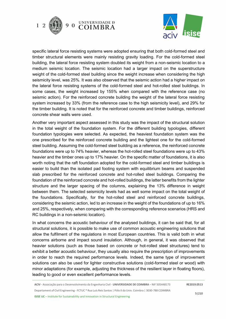
specific lateral force resisting systems were adopted ensuring that both cold-formed steel and timber structural elements were mainly resisting gravity loading. For the cold-formed steel building, the lateral force resisting system doubled its weight from a non-seismic location to a medium seismic location. The seismic location had a larger impact on the superstructure weight of the cold-formed steel building since the weight increase when considering the high seismicity level, was 25%. It was also observed that the seismic action had a higher impact on the lateral force resisting systems of the cold-formed steel and hot-rolled steel buildings. In some cases, the weight increased by 155% when compared with the reference case (no seismic action). For the reinforced concrete building the weight of the lateral force resisting system increased by 33% (from the reference case to the high seismicity level), and 29% for the timber building. It is noted that for the reinforced concrete and timber buildings, reinforced concrete shear walls were used.
Another very important aspect assessed in this study was the impact of the structural solution in the total weight of the foundation system. For the different building typologies, different foundation typologies were selected. As expected, the heaviest foundation system was the one prescribed for the reinforced concrete building and the lightest one for the cold-formed steel building. Assuming the cold-formed steel building as a reference, the reinforced concrete foundations were up to 74% heavier, whereas the hot-rolled steel foundations were up to 43% heavier and the timber ones up to 17% heavier. On the specific matter of foundations, it is also worth noting that the raft foundation adopted for the cold-formed steel and timber buildings is easier to build than the isolated pad footing system with equilibrium beams and suspended slab prescribed for the reinforced concrete and hot-rolled steel buildings. Comparing the foundation of the reinforced concrete and hot-rolled buildings, the latter benefits from the lighter structure and the larger spacing of the columns, explaining the 13% difference in weight between them. The selected seismicity levels had as well some impact on the total weight of the foundations. Specifically, for the hot-rolled steel and reinforced concrete buildings, considering the seismic action, led to an increase in the weight of the foundations of up to 16% and 25%, respectively, when comparing with the corresponding reference scenarios (HRS and RC buildings in a non-seismic location).
In what concerns the acoustic behaviour of the analysed buildings, it can be said that, for all structural solutions, it is possible to make use of common acoustic engineering solutions that allow the fulfilment of the regulations in most European countries. This is valid both in what concerns airborne and impact sound insulation. Although, in general, it was observed that heavier solutions (such as those based on concrete or hot-rolled steel structures) tend to exhibit a better acoustic behaviour, they usually also require the prescription of improvements in order to reach the required performance levels. Indeed, the same type of improvement solutions can also be used for lighter constructive solutions (cold-formed steel or wood) with minor adaptations (for example, adjusting the thickness of the resilient layer in floating floors), leading to good or even excellent performance levels.

ACIV - Associação para o Desenvolvimento da Engenharia Civil - UNIVERSIDADE DE COIMBRA – NIF 505448173
Departament of Civil Engineering - FCTUC * Rua Luís Reis Santos | Pólo II da Univ. Coimbra | 3030-788 COIMBRA
ISISE UC – Institute for Sustainability and Innovation in Structural Engineering
RE2019.0513
6|210
It should be noted that, in what concerns the acoustic performance, the predicted results are calculated considering proper execution conditions. However, it must be stressed that the final result (in situ) is strongly dependent on the constructive process and on specific details. The achievement of adequate acoustic insulation conditions in buildings is not only due to the adoption of appropriate constructive solutions, as it was intended to value in this study, but also by the compatibility with the other project specialities involved, their detailing and the correct on-site execution. A solution of predictable high acoustic performance can result in failure even if very small execution errors are made (such as the application of electrical outlets on both sides of lightweight partition walls). It is worth emphasizing the advantages of prefabrication in the building construction industry. Prefabricated solutions will have a lower impact on the construction site and its surroundings, reducing waste. Moreover, these solutions present higher potential and inherent added value in terms of versatility, adaptability and expansion of the building. Lightweight solutions with faster construction schedules may bring additional cost savings in different construction operations. For instance, the reduced number of onsite works will lead to lower waste and lower disposal costs, as well as to increased safety levels for the workers, whereas the reduced construction schedules will lead to reduced costs and usage of elevation equipment.
Regarding the fire resistance of the tested solutions, as expected, the steel ones require passive fire protection for the structural elements due to their high section factor and high thermal conductivity of steel. Since all walls are loadbearing in the CFS solution, this solution will require the larger quantity of passive fire protection, however it is worth mentioning that the steel solutions are non-combustible, hence they do not contribute to increase the fire load of the building.
For the studied cases, a detailed construction schedule was conducted, assessing the competitiveness of each framing solution in terms of the duration of the construction. A detailed analysis was undertaken, ensuring that practical erection sequence and simplicity of assembly are taken into consideration. The construction schedule is a very important factor in the decision process. Faster construction schedules will lead to lower costs and potentially earlier income for the owner, depending on the business model established. From the conducted analysis, clearly, the prefabricated cold-formed steel solution is more competitive in terms of the overall duration, bearing in mind that the off-site time for preparation was not considered in this analysis. It was assumed that with proper planning the off-site time for preparation of the pre-fabricated solutions will not influence the on-site construction duration. Comparing the reinforced concrete with the cold-formed steel framing solution, the construction times can be reduced by about 23% for the reference case and 22% for the high seismic case for this specific building. Comparing the reinforced concrete with the hot-rolled steel framing solution, the construction times can be reduced by about 8.8% for the reference case and 8.7% for the high seismic case. Comparing the reinforced concrete with the timber framing solution, the construction times can be reduced by about 7% for the reference case and 10% for the high

ACIV - Associação para o Desenvolvimento da Engenharia Civil - UNIVERSIDADE DE COIMBRA – NIF 505448173
Departament of Civil Engineering - FCTUC * Rua Luís Reis Santos | Pólo II da Univ. Coimbra | 3030-788 COIMBRA
ISISE UC – Institute for Sustainability and Innovation in Structural Engineering
RE2019.0513
7|210
seismic case. In terms of the estimated total cost (based on labor, material and transportation costs, foundations and structural system, cladding, finishes, etc.) (estimation based on the current best practice in Portugal) the solutions are found very similar with variation about 10% in price of the different systems. However, significant differences were found in terms of transportation requirements, where he Reinforced Concrete solutions need almost two times more trucks coming onsite.
As a final note, it is worth mentioning that the outcome of this study is valid for the type of building studied, with a similar utilization, volume and built at the selected locations with the corresponding environmental and accidental actions. This study was conducted trying to optimize different structural solutions for a fixed architectural layout that did not allow to fully exploit some key advantages of some of the structural solutions (e.g., steel-framed solution with large free spans using cellular beams). However, this is a common situation in many real estate developments throughout Europe, where there is little freedom to implement the necessary adjustments to the architectural project to be able to optimize the full project. Hence, if other types of buildings are considered, the conclusions may be slightly different. For this reason, a broader study may be needed, covering a larger sample of residential buildings in order to assess the achieve more general conclusions and best practice guidance. Nevertheless, the type of information produced may be of outmost relevance not only for the civil engineering community but as well for owners and all stakeholders involved in the building construction industry. Finally, it is also noted that the life-cycle assessment is not included in this report, so that the overall competitiveness of the studied structural solutions for low to medium-rise residential buildings may vary if sustainability aspects are considered.
ACIV - Associação para o Desenvolvimento da Engenharia Civil - UNIVERSIDADE DE COIMBRA – NIF 505448173
Departament of Civil Engineering - FCTUC * Rua Luís Reis Santos | Pólo II da Univ. Coimbra | 3030-788 COIMBRA
ISISE UC – Institute for Sustainability and Innovation in Structural Engineering
RE2019.0513
8|210
TABLE OF CONTENTS
EXECUTIVE SUMMARY ......................................................................................... 3
1. SCOPE ............................................................................................................ 24
1.1 INTRODUCTION ................................................................................................ 24
1.2 MAIN ASSUMPTIONS ....................................................................................... 25
2. CASE STUDY – FORCATECH BUILDING - A ............................................... 32
3. FACADES AND INTERNAL PARTITIONS ..................................................... 36
4. CONCEPTUAL DESIGN ................................................................................. 39
4.1 GENERAL CONSIDERATIONS ......................................................................... 39
4.2 COLD-FORMED STEEL .................................................................................... 41
4.2.1 Description of the structural system I – Hot-rolled steel lateral load resisting system 41
4.2.2 Description of the structural system II – Reinforced concrete lateral load resisting system ........................................................................................................ 44
4.2.3 Foundations .................................................................................................. 45
4.3 HOT-ROLLED STEEL ........................................................................................ 45
4.3.1 Description of the structural system I – Hot-rolled steel moment resisting frames as lateral load resisting system ................................................................................. 45
4.3.2 Description of the structural system II – Reinforced concrete core as lateral load resisting system ........................................................................................................ 46
4.3.3 Foundations .................................................................................................. 48
4.4 REINFORCED CONCRETE ............................................................................... 48
4.4.1 Description of the structural system ............................................................... 48
4.4.2 Foundations .................................................................................................. 49
4.5 TIMBER ............................................................................................................. 50
4.5.1 Description of the structural system ............................................................... 50
4.5.2 Foundations .................................................................................................. 51
4.6 REINFORCED CONCRETE SHEAR WALL SYSTEM ....................................... 51
4.6.1 Description of the structural system ............................................................... 51
ACIV - Associação para o Desenvolvimento da Engenharia Civil - UNIVERSIDADE DE COIMBRA – NIF 505448173
Departament of Civil Engineering - FCTUC * Rua Luís Reis Santos | Pólo II da Univ. Coimbra | 3030-788 COIMBRA
ISISE UC – Institute for Sustainability and Innovation in Structural Engineering
RE2019.0513
9|210
4.6.2 Structural fire design ..................................................................................... 52
4.6.3 Foundations .................................................................................................. 52
4.7 SUMMARY ......................................................................................................... 52
5. COMPARATIVE STUDY ................................................................................. 54
5.1 BILL OF MATERIALS ......................................................................................... 54
5.1.1 Light-steel framing solution ............................................................................ 54
5.1.2 Hot-Rolled Solution ....................................................................................... 58
5.1.3 Reinforced Concrete Solution ........................................................................ 61
5.1.4 Timber solution .............................................................................................. 63
5.1.5 Reinforced concrete shear wall system ......................................................... 65
5.1.6 Weight comparison ........................................................................................ 66
5.2 INFLUENCE OF THE SEISMICITY LEVEL ........................................................ 71
5.2.1 Introduction ................................................................................................... 71
5.2.2 CFS solution .................................................................................................. 71
5.2.3 HRS solution ................................................................................................. 75
5.2.4 Reinforced concrete solution ......................................................................... 80
5.2.5 Timber solution .............................................................................................. 83
5.2.6 Reinforced Concrete Shear Wall System ....................................................... 85
5.2.7 Comparison between all different structural solutions .................................... 86
5.3 IMPACT ON FOUNDATIONS ............................................................................ 95
5.4 CONCRETE CONSUMPTION ......................................................................... 101
5.5 ACOUSTIC PERFORMANCE .......................................................................... 103
5.5.1 Cold-Formed Steel ...................................................................................... 103
5.5.2 Hot-Rolled Steel .......................................................................................... 111
5.5.3 Reinforced Concrete ................................................................................... 115
5.5.4 Timber ......................................................................................................... 119
5.5.5 Reinforced Concrete Shear Wall System ..................................................... 119
5.5.6 Comparison Between the Proposed Solutions ............................................. 124
5.5.7 Summary ..................................................................................................... 130

ACIV - Associação para o Desenvolvimento da Engenharia Civil - UNIVERSIDADE DE COIMBRA – NIF 505448173
Departament of Civil Engineering - FCTUC * Rua Luís Reis Santos | Pólo II da Univ. Coimbra | 3030-788 COIMBRA
ISISE UC – Institute for Sustainability and Innovation in Structural Engineering
RE2019.0513
10|210
5.6 STRUCTURAL FIRE DESIGN ......................................................................... 132
5.6.1 General Considerations ............................................................................... 132
5.6.2 Cold-Formed Steel ...................................................................................... 133
5.6.3 Hot-Rolled Steel .......................................................................................... 135
5.6.4 Reinforced Concrete ................................................................................... 139
5.6.5 Timber ......................................................................................................... 140
5.6.6 Comparison Between the Proposed Solutions ............................................. 141
6. CONSTRUCTION SCHEDULE ..................................................................... 143
6.1 INTRODUCTION .............................................................................................. 143
6.2 COMPARISON OF THE CONSTRUCTION SCHEDULES ............................... 145
6.3 SITE PLANNING .............................................................................................. 151
6.3.1 Organization of the construction site and technology of execution ............... 151
6.3.2 Cold-formed steel solution ........................................................................... 151
6.3.3 Hot-rolled steel solution ............................................................................... 152
6.3.4 Reinforced concrete solution ....................................................................... 153
6.3.5 Timber solution ............................................................................................ 155
6.3.6 Comparison of the on-site craning costs for all solutions ............................. 156
6.4 TRANSPORTATION ........................................................................................ 157
6.5 TOTAL COSTS ................................................................................................ 159
6.6 FINAL REMARKS ............................................................................................ 162
7. CONCLUSIONS ............................................................................................ 164
8. REFERENCES .............................................................................................. 169
ANNEX A. FACADES AND INTERNAL PARTITIONS ................................................. 172
A1. FACADE SYSTEM ................................................................................................. 172
A2. ELEVATORS AND STAIRS .................................................................................... 173
A3. INTERNAL PARTITIONING ................................................................................... 175
ANNEX B. ACTIONS AND LOAD COMBINATIONS ................................................... 180
B1. GENERAL SAFETY CRITERIA, ACTIONS AND COMBINATION OF ACTIONS ... 180
B2. PERMANENT ACTIONS ........................................................................................ 180
ACIV - Associação para o Desenvolvimento da Engenharia Civil - UNIVERSIDADE DE COIMBRA – NIF 505448173
Departament of Civil Engineering - FCTUC * Rua Luís Reis Santos | Pólo II da Univ. Coimbra | 3030-788 COIMBRA
ISISE UC – Institute for Sustainability and Innovation in Structural Engineering
RE2019.0513
11|210
B3. IMPOSED LOADS .................................................................................................. 180
B4. WIND ACTIONS ..................................................................................................... 181
B3.5. Calculation of mean wind velocity 𝑣𝑚(𝑧) .................................................. 185
B3.6. Calculation of the turbulence intensity 𝐼𝑣 .................................................. 186
B3.7. Calculation of external and internal pressures ......................................... 186
B5. SEISMIC ACTIONS ................................................................................................ 187
B4.1. Introduction .................................................................................................... 187
B4.2. Medium seismicity area ............................................................................... 189
B4.3. High seismicity area ..................................................................................... 189
B6. LOAD COMBINATIONS ......................................................................................... 193
ANNEX C. LIGHT STEEL FRAMING ........................................................................... 194
C1. SUPERSTRUCTURE - REFERENCE CASE.......................................................... 194
C2. SUPERSTRUCTURE - MEDIUM SEISMICITY LEVEL ........................................... 195
C3. SUPERSTRUCTURE - HIGH SEISMICITY LEVEL ................................................ 196
C4. FOUNDATIONS – REFERENCE ............................................................................ 197
ANNEX D. HOT-ROLLED STEEL SOLUTION ............................................................. 198
D1. SUPERSTRUCTURE - REFERENCE .................................................................... 198
D2. SUPERSTRUCTURE - MEDIUM SEISMICITY LEVEL ........................................... 199
D3. SUPERSTRUCTURE - HIGH SEISMICITY LEVEL ................................................ 200
D4. FOUNDATIONS – REFERENCE ............................................................................ 201
D5. FOUNDATIONS – MEDIUM / HIGH SEISMICITY LEVEL ...................................... 202
ANNEX E. REINFORCED CONCRETE SOLUTION .................................................... 203
E1. SUPERSTRUCTURE - REFERENCE .................................................................... 203
E2. SUPERSTRUCTURE - MEDIUM SEISMICITY LEVEL ........................................... 204
E3. SUPERSTRUCTURE - HIGH SEISMICITY LEVEL ................................................ 205
E4. FOUNDATIONS – REFERENCE ............................................................................ 206
E5. FOUNDATIONS – MEDIUM / HIGH SEISMICITY LEVELS .................................... 207
ANNEX F. TIMBER SOLUTION ................................................................................... 208
F1. SUPERSTRUCTURE - REFERENCE .................................................................... 208

ACIV - Associação para o Desenvolvimento da Engenharia Civil - UNIVERSIDADE DE COIMBRA – NIF 505448173
Departament of Civil Engineering - FCTUC * Rua Luís Reis Santos | Pólo II da Univ. Coimbra | 3030-788 COIMBRA
ISISE UC – Institute for Sustainability and Innovation in Structural Engineering
RE2019.0513
12|210
F2. SUPERSTRUCTURE – MEDIUM / HIGH SEISMICITY LEVEL .............................. 209
F3. FOUNDATIONS ..................................................................................................... 210

ACIV - Associação para o Desenvolvimento da Engenharia Civil - UNIVERSIDADE DE COIMBRA – NIF 505448173
Departament of Civil Engineering - FCTUC * Rua Luís Reis Santos | Pólo II da Univ. Coimbra | 3030-788 COIMBRA
ISISE UC – Institute for Sustainability and Innovation in Structural Engineering
RE2019.0513
13|210
LIST OF FIGURES
Figure 1.1. Adopted case study - FORCATECH BUILDING – A. ......................................... 25
Figure 2.1. Comparison between the original and modified ground floor configuration. ........ 33
Figure 2.2. Anchor bolts and Simpson holdown devices. ..................................................... 34
Figure 2.3. Floor joists and composite floor. ......................................................................... 34
Figure 2.4. Details on the foundations for the reference building. a) Raft foundation at an external load bearing wall. b) Raft foundation at an internal load bearing wall...................... 35
Figure 3.1. Koppen-Geiger climate classification for Europe. (Peel et al. (2007)) ................. 36
Figure 3.2. Partitioning solutions to be adopted. .................................................................. 37
Figure 4.1. Design concepts according to EN 1998-1 [17] ................................................... 39
Figure 4.2. Structural layout for the light-steel framing building [12]. .................................... 42
Figure 4.3. Structural layout for the light-steel framing building [25]. .................................... 42
Figure 4.4. Structural layout for the light-steel framing building. ........................................... 43
Figure 4.5. Structural layout for the light-steel framing building with reinforced concrete shear walls for the reference scenario. .......................................................................................... 44
Figure 4.6. Hot-rolled steel structural layout. ........................................................................ 46
Figure 4.7 New hot-rolled steel structural layout considering a reinforced concrete core and for the reference situation. ........................................................................................................ 47
Figure 4.8. Reinforced concrete with flat slabs structural layout. .......................................... 49
Figure 4.9. Timber with shear walls structural layout. ........................................................... 50
Figure 5.1. Total weight comparison between the initial structural solutions, for the reference case (without seismic action). .............................................................................................. 67
Figure 5.2. Total weight comparison between all tested structural solutions, for the reference case (without seismic action). .............................................................................................. 68
Figure 5.3. Total weight (per sqm) comparison between the initial structural solutions, for the reference case (without seismic action). .............................................................................. 69
Figure 5.4. Total weight (per sqm) comparison between all tested structural solutions, for the reference case (without seismic action). .............................................................................. 70
Figure 5.5. Total weight comparison between all tested seismic scenarios (G550). ............. 72
Figure 5.6. The weight of the superstructure for the different seismic scenarios (G550). ..... 72

ACIV - Associação para o Desenvolvimento da Engenharia Civil - UNIVERSIDADE DE COIMBRA – NIF 505448173
Departament of Civil Engineering - FCTUC * Rua Luís Reis Santos | Pólo II da Univ. Coimbra | 3030-788 COIMBRA
ISISE UC – Institute for Sustainability and Innovation in Structural Engineering
RE2019.0513
14|210
Figure 5.7. Total weight comparison between all tested seismic scenarios (G550) with RC core. ............................................................................................................................................ 73
Figure 5.8 - Total weight comparison between all tested seismic scenarios (S320). ............ 73
Figure 5.9 - Weight of the superstructure for the different seismic scenarios (S320). ........... 74
Figure 5.10. Total weight comparison between all tested seismic scenarios (S320GD+Z) with RC core. .............................................................................................................................. 75
Figure 5.11. Total weight comparison between all tested seismic scenarios, considering the S355 steel. ........................................................................................................................... 75
Figure 5.12. Total weight comparison between all tested seismic scenarios, considering the S460 steel. ........................................................................................................................... 76
Figure 5.13. Total weight comparison between tested seismicity levels, considering both S355 and S460 steels. .................................................................................................................. 76
Figure 5.14. Hot-rolled steel weight comparison for the tested scenarios, considering both DCM and DCH, with the correspondent behaviour factors q=4 and q=6.5. .......................... 77
Figure 5.15. Weight comparisons for all tested cases – Hot-Rolled Steel building [kg/m2], considering the S355 steel. .................................................................................................. 78
Figure 5.16. Weight comparisons for all tested cases – Hot-Rolled Steel building [kg/m2], considering the S460 steel ................................................................................................... 78
Figure 5.17. Total weight comparison between all tested seismic scenarios, considering the S355 steel and a reinforced concrete core. .......................................................................... 79
Figure 5.18. Total weight comparison between all tested seismic scenarios, considering the S460 steel and a reinforced concrete core. .......................................................................... 79
Figure 5.19. Total weight comparison between all tested scenarios for the reinforced concrete building. ............................................................................................................................... 80
Figure 5.20. Comparison between all tested scenarios for the superstructure and flat slabs. ............................................................................................................................................ 81
Figure 5.21. Comparison between all tested scenarios for the superstructure. .................... 81
Figure 5.22. Weight comparisons for all tested cases – Reinforced concrete building [kg/m2]. ............................................................................................................................................ 82
Figure 5.23. Reinforced concrete weight comparison for the tested scenarios, considering DCM, with the following behaviour factors q=3 and q=3.9. ................................................... 83
Figure 5.24. Total weight comparison between all tested seismic scenarios. ....................... 83
Figure 5.25. Total weight of the superstructure for all tested seismic scenarios. .................. 84

ACIV - Associação para o Desenvolvimento da Engenharia Civil - UNIVERSIDADE DE COIMBRA – NIF 505448173
Departament of Civil Engineering - FCTUC * Rua Luís Reis Santos | Pólo II da Univ. Coimbra | 3030-788 COIMBRA
ISISE UC – Institute for Sustainability and Innovation in Structural Engineering
RE2019.0513
15|210
Figure 5.26. Weight per square meter of the superstructure for all tested seismic scenarios. ............................................................................................................................................ 85
Figure 5.27. Total weight comparison between all tested seismic scenarios. ....................... 85
Figure 5.28. Total weight comparison between initially tested structural solutions. .............. 86
Figure 5.29. Total weight comparison between all tested structural solutions. ..................... 88
Figure 5.30. Total weight comparison for the superstructure elements between the initially tested structural solutions. ................................................................................................... 89
Figure 5.31. Total weight comparison for the superstructure elements between the all tested structural solutions. .............................................................................................................. 89
Figure 5.32. Comparison of the superstructure elements between initially tested structural solutions. ............................................................................................................................. 90
Figure 5.33. Comparison of the superstructure elements between all tested structural solutions. ............................................................................................................................. 90
Figure 5.34. Comparison of the individualized superstructure elements between all tested structural solutions. .............................................................................................................. 91
Figure 5.35. Total weight per sqm comparison between initially tested structural solutions. . 91
Figure 5.36. Total weight per sqm comparison between all tested structural solutions. ........ 92
Figure 5.37. Frames and walls´ weight increase in % between the initially tested structural solutions. ............................................................................................................................. 93
Figure 5.38. Frames and walls´ weight increase in % between all tested structural solutions. ............................................................................................................................................ 94
Figure 5.39. Total base reaction in the X direction. .............................................................. 95
Figure 5.40 - Total base reaction in the Y direction. ............................................................. 96
Figure 5.41. Total base reaction in the Z direction. .............................................................. 96
Figure 5.42. Weight comparison for the different foundation systems adopted for initially defined type of buildings as a function of the seismicity level. .............................................. 98
Figure 5.43. Weight comparison for the different foundation systems adopted for all buildings as a function of the seismicity level. ..................................................................................... 98
Figure 5.44. Comparison between the different foundation systems adopted for each type of building as a function of the seismicity level. ........................................................................ 99
Figure 5.45. Comparison between the different foundation systems adopted for all types of buildings investigated as a function of the seismicity level. .................................................. 99

ACIV - Associação para o Desenvolvimento da Engenharia Civil - UNIVERSIDADE DE COIMBRA – NIF 505448173
Departament of Civil Engineering - FCTUC * Rua Luís Reis Santos | Pólo II da Univ. Coimbra | 3030-788 COIMBRA
ISISE UC – Institute for Sustainability and Innovation in Structural Engineering
RE2019.0513
16|210
Figure 5.46. Variation of the weight of the foundations for the initially studied scenarios. ... 100
Figure 5.47. Variation of the weight of the foundations for all studied scenarios. ................ 100
Figure 5.48. Concrete weight per building type and weight of the materials in the concrete mix for the reference cases. ..................................................................................................... 101
Figure 5.49. Concrete weight per building type and weight of the materials in the concrete mix for the high seismic cases. ................................................................................................. 102
Figure 5.50. Improvement solutions for slab floor coverings of solution “Cold-Formed Steel”: a) Floating floor covering 1 (8mm); b) Flooring platform. ........................................................ 105
Figure 5.51. Improvement solutions for suspended ceilings under the slab: a) Basic ceiling (with rigid suspension); b) High performance ceiling 1; c) High performance ceiling 2. ...... 105
Figure 5.52. Direct partition walls (between apartments or between circulation zones and apartments): a) Basic lightweight partition; b) High performance partition; c) Lightweight partition with reinforced structure. ...................................................................................... 106
Figure 5.53. Internal partition walls considered (inside each apartment): a) Basic lightweight partition; b) High performance partition. ............................................................................. 110
Figure 5.54. Improvement solutions for slab floor coverings of solution “Hot-Rolled Steel”: a) Floating floor covering 2 (4mm); b) Flooring platform. ........................................................ 111
Figure 5.55 Comparison between expected results of the airborne sound insulation of the façade, for the three types of façades evaluated. ............................................................... 124
Figure 5.56 Comparison between airborne sound insulation between rooms on the same floor, considering base false ceiling and floating floor covering. .................................................. 125
Figure 5.57 Comparison of airborne sound insulation between bedrooms on the same floor, considering the basic suspended ceiling and the floor system through a floating platform. 125
Figure 5.58 Comparison of airborne sound insulation of floors between adjacent bedrooms, considering the floating floor covering and three types of false ceilings. ............................ 126
Figure 5.59 Comparison of airborne sound insulation of floors between adjacent bedrooms, considering the floating floor platform and two types of suspended ceilings (extreme situations). ......................................................................................................................... 127
Figure 5.60 Comparison between results of the impact noise transmission between bedrooms on the same floor, considering the basic suspended ceiling and the basic partition. .......... 127
Figure 5.61 Comparison between results of the impact noise transmission, between bedrooms of different floors, considering the basic partition. .............................................................. 128
ACIV - Associação para o Desenvolvimento da Engenharia Civil - UNIVERSIDADE DE COIMBRA – NIF 505448173
Departament of Civil Engineering - FCTUC * Rua Luís Reis Santos | Pólo II da Univ. Coimbra | 3030-788 COIMBRA
ISISE UC – Institute for Sustainability and Innovation in Structural Engineering
RE2019.0513
17|210
Figure 5.62 Comparison of airborne sound insulation between common circulation areas and adjacent living rooms, considering the basic partition and suspended ceiling, for two types of doors and two types of floor improvement solutions. .......................................................... 129
Figure 5.63 Comparison between results of the transmission of impact noise, between common circulation zones and adjacent living rooms, considering the basic suspended ceiling and the basic partition configuration. .................................................................................. 129
Figure 5.64 Comparison between airborne sound insulation between rooms of the same apartment, considering the basic suspended ceiling, for two types of partitions and two types of floor improvement solutions. .......................................................................................... 130
Figure 5.65 Comparison between results of impact noise transmission between rooms of the same apartment, considering the basic partition and suspended ceiling. ........................... 130
Figure 5.66 Structural fire behavior of a CFS member in compression and exposed to fire during 60 minutes: a) temperature distribution; b and c) deformed configuration; d) axial displacement as a function of time. .................................................................................... 134
Figure 5.67 Estimated quantities of gypsum boards from Saint-Gobain for the commonly used CFS solution ...................................................................................................................... 135
Figure 5.68 Estimated quantities of gypsum boards from Saint-Gobain for the high performance CFS solution ................................................................................................. 135
Figure 5.69 Estimated quantities of gypsum boards from Saint-Gobain for the commonly used HRS solution ...................................................................................................................... 137
Figure 5.70 Estimated quantities of gypsum boards from Saint-Gobain for the high performance HRS solution ................................................................................................. 137
Figure 5.71 Estimated quantities of gypsum boards from Saint-Gobain for the commonly used HRS solution ...................................................................................................................... 138
Figure 5.72 Structural fire behavior of a composite slab under fire during 60 minutes (MACS+ software) ............................................................................................................................ 138
Figure 5.73 - Estimated quantities of gypsum boards from Saint-Gobain for the commonly used RC solution ........................................................................................................................ 139
Figure 5.74 - Estimated quantities of gypsum boards from Saint-Gobain for the high performance RC solution ................................................................................................... 140
Figure 5.75 - Estimated quantities of gypsum boards from Saint-Gobain for the commonly used T solution ........................................................................................................................... 141
Figure 5.76 - Estimated quantities of gypsum boards from Saint-Gobain for the high performance T solution ...................................................................................................... 141

ACIV - Associação para o Desenvolvimento da Engenharia Civil - UNIVERSIDADE DE COIMBRA – NIF 505448173
Departament of Civil Engineering - FCTUC * Rua Luís Reis Santos | Pólo II da Univ. Coimbra | 3030-788 COIMBRA
ISISE UC – Institute for Sustainability and Innovation in Structural Engineering
RE2019.0513
18|210
Figure 6.1.Representative construction schedule. .............................................................. 145
Figure 6.2. Comparison of the construction schedule per activity, for the reference case. . 146
Figure 6.3. Comparison of the construction schedule per activity, for the high seismic case. .......................................................................................................................................... 146
Figure 6.4. Estimated total duration for the execution programme for all framing solutions and reference case. .................................................................................................................. 150
Figure 6.5. Estimated total duration for the execution programme for all framing solutions and high seismic case. ............................................................................................................. 150
Figure 6.6. Construction site planning – CFS solution ........................................................ 152
Figure 6.7. Construction site planning – HRS solution ....................................................... 153
Figure 6.8. Construction site planning – RC solution .......................................................... 154
Figure 6.9. Construction site planning – Timber solution .................................................... 155
Figure 6.10. On-site craning costs reference solution ........................................................ 156
Figure 6.11. On-site craning costs HS ............................................................................... 157
Figure 6.12. Total number of trucks – ref ........................................................................... 157
Figure 6.13. Total number of trucks – HS ........................................................................... 158
Figure 6.14. Number of trucks per category – Ref .............................................................. 159
Figure 6.15. Number of trucks per category – HS .............................................................. 159
Figure 6.16. Total construction costs – reference case ...................................................... 160
Figure 6.17. Total construction costs – HS ......................................................................... 160
Figure 6.18. Total construction costs – Ref ........................................................................ 161
Figure 6.19. Total construction costs – HS ......................................................................... 161
Figure A.1. Schematic representation of the Direct render (a)) and ETICS system (b)). ..... 172
Figure A.2. Schematic representation of the Double external wall with Direct Render System (a)) and the Double External wall with ETICS system (b)). ................................................. 173
Figure A.3. Schematic representation of the External wall with Cladding system (Glasroc ® X). .......................................................................................................................................... 173
Figure B.1. Velocity pressure distribution on face D (𝜃 = 0º, 𝜃 = 90º). ............................... 182
Figure B.2. Pressure zones for wind direction θ=0⁰ ............................................................ 183
ACIV - Associação para o Desenvolvimento da Engenharia Civil - UNIVERSIDADE DE COIMBRA – NIF 505448173
Departament of Civil Engineering - FCTUC * Rua Luís Reis Santos | Pólo II da Univ. Coimbra | 3030-788 COIMBRA
ISISE UC – Institute for Sustainability and Innovation in Structural Engineering
RE2019.0513
19|210
Figure B.3. Pressure zones for wind direction θ=90⁰. ......................................................... 183
Figure B.4. External and internal coefficients. .................................................................... 184
Figure B.5. Wind pressures (kN/m2) on walls, for a) θ=0⁰ and b) θ=90⁰. ............................ 187
Figure B.6. Design concepts according to EN 1998-1. ....................................................... 189
Figure B.7. Type of ground classification via the Tc spectrum period, National Annex P100/1-2013 .................................................................................................................................. 190
Figure B.8. The design ground acceleration 𝑎𝑔 for an event with MRI=225 years and an exceeding probability of 20% ............................................................................................. 191
Figure B.9. Normalised elastic response spectrum 𝛽(𝑡) for corner periods TB, TC and TD 192
ACIV - Associação para o Desenvolvimento da Engenharia Civil - UNIVERSIDADE DE COIMBRA – NIF 505448173
Departament of Civil Engineering - FCTUC * Rua Luís Reis Santos | Pólo II da Univ. Coimbra | 3030-788 COIMBRA
ISISE UC – Institute for Sustainability and Innovation in Structural Engineering
RE2019.0513
20|210
LIST OF TABLES
Table 1.1. The density of different materials used in the concrete mix. ................................ 26
Table 1.2. The composition of the concrete mix considered. ................................................ 26
Table 1.3. Summary of the construction options tested. ....................................................... 27
Table 1.4 Typical acoustic performance requirements in European countries (between apartments in a multi-storey building) [13]. ........................................................................... 29
Table 1.5 Acoustic performance requirements proposed, taking into account the requirements in different European countries, and considering two performance levels. ........................... 30
Table 2.1. Relevant physical characteristics. ....................................................................... 32
Table 4.1. Behaviour factors q. ............................................................................................ 40
Table 5.1. Bill of structural materials – cold-formed steel solution (G550) with HRS core. .... 55
Table 5.2. Bill of structural materials – cold-formed steel solution (G550) with RC core. ...... 55
Table 5.3. Bill of structural materials (ton) according to the defined categories – cold-formed steel solution (G550) . .......................................................................................................... 56
Table 5.4. Bill of structural materials – cold-formed steel solution (S320). ............................ 56
Table 5.5. Bill of structural materials – cold-formed steel solution (S320) with RC core. ...... 57
Table 5.6. Bill of structural materials (ton) according to the defined categories – cold-formed steel solution (S320) with hot-rolled steel core and strengthening frames. ........................... 57
Table 5.7. Estimated quantities based on the C30/37 concrete composition for the original solutions with hot-rolled steel lateral load resisting system. .................................................. 58
Table 5.8. Estimated quantities based on the C30/37 concrete composition for the CFS building with reinforced concrete core. ................................................................................. 58
Table 5.9. Bill of structure materials - HRS solution (S355). ................................................. 59
Table 5.10. Bill of structural materials according to the defined categories – HRS solution. . 60
Table 5.11. Bill of materials for the structure – HRS solution (S355) with reinforced concrete core. .................................................................................................................................... 60
Table 5.12. Bill of structure materials - HRS solution (S460). ............................................... 60
Table 5.13. Bill of materials for the structure – HRS solution (S355) with reinforced concrete core. .................................................................................................................................... 61
Table 5.14. Estimated quantities based on the C30/37 concrete composition for the situation with a hot-rolled lateral force resisting system. ..................................................................... 61
ACIV - Associação para o Desenvolvimento da Engenharia Civil - UNIVERSIDADE DE COIMBRA – NIF 505448173
Departament of Civil Engineering - FCTUC * Rua Luís Reis Santos | Pólo II da Univ. Coimbra | 3030-788 COIMBRA
ISISE UC – Institute for Sustainability and Innovation in Structural Engineering
RE2019.0513
21|210
Table 5.15. Dimensions of the structural elements. .............................................................. 62
Table 5.16. Bill of structure materials - RC solution .............................................................. 63
Table 5.17. Estimated quantities based on the C30/37 concrete composition. ..................... 63
Table 5.18. Bill of structure materials – timber building. ....................................................... 64
Table 5.19. Estimated quantities based on the C30/37 concrete composition. ..................... 64
Table 5.20. Bill of structure materials – RC shear walls solution .......................................... 65
Table 5.21. Estimated quantities based on the C30/37 concrete composition. ..................... 66
Table 5.22. Comparison of total structural materials weight. ................................................ 67
Table 5.23. Comparison of structural materials weight per sqm. .......................................... 69
Table 5.24. Comparison of the total structural materials weight. .......................................... 87
Table 5.25. Comparison of structural materials weight per sqm. .......................................... 92
Table 5.26. Weight estimation for the foundations according to the investigated scenarios. 97
Table 5.27. Airborne sound insulation results between the exterior and rooms or kitchens (for the most unfavourable situations). ..................................................................................... 103
Table 5.28.Sound insulation results between bedrooms or between living rooms of different apartments of the same floor. ............................................................................................ 106
Table 5.29. Sound insulation results between rooms or between rooms of different apartments of different floors. ............................................................................................................... 108
Table 5.30. Sound insulation results between common areas and adjacent rooms (living rooms or bedrooms), with two types of entrance doors to the apartments. ................................... 109
Table 5.31 Sound insulation results between rooms in the same apartment – Cold formed steel structure. ............................................................................................................................ 110
Table 5.32. Sound insulation results between bedrooms or between living rooms of different apartments of the same floor - Hot-Rolled Steel. ................................................................ 112
Table 5.33. Sound insulation results between rooms or between rooms of different apartments of different floors - Hot-Rolled Steel. .................................................................................. 113
Table 5.34. Sound insulation results between common areas and adjacent rooms (living rooms or bedrooms), with two types of entrance doors to the apartments - Hot-Rolled Steel........ 114
Table 5.35 Sound insulation results between rooms in the same dwelling - Hot-Rolled Steel. .......................................................................................................................................... 115
Table 5.36. Results of sound insulation between bedrooms or between living rooms of different apartments of the same floor - Reinforced Concrete. ......................................................... 116

ACIV - Associação para o Desenvolvimento da Engenharia Civil - UNIVERSIDADE DE COIMBRA – NIF 505448173
Departament of Civil Engineering - FCTUC * Rua Luís Reis Santos | Pólo II da Univ. Coimbra | 3030-788 COIMBRA
ISISE UC – Institute for Sustainability and Innovation in Structural Engineering
RE2019.0513
22|210
Table 5.37. Results of sound insulation between bedrooms or between living rooms of apartments on different floors - Reinforced Concrete. ........................................................ 117
Table 5.38 Results of sound insulation between common circulation areas and adjacent rooms, with two types of access doors to dwellings - Reinforced Concrete. ................................... 118
Table 5.39 Sound insulation results between rooms in the same dwelling - Reinforced Concrete. ........................................................................................................................... 118
Table 5.40 Results of airborne sound insulation between the exterior and rooms or kitchens (for the most unfavourable situations) - Reinforced concrete with concrete walls ............... 120
Table 5.41. Results of sound insulation between rooms or between rooms of different apartments of the same floor - Reinforced concrete with concrete walls. ........................... 121
Table 5.42. Results of sound insulation between bedrooms or between living rooms of apartments of different floors - Reinforced concrete with concrete walls. ........................... 121
Table 5.43. Results of sound isolation between common circulation zones and adjacent rooms, with two types of access doors to the apartments- Reinforced concrete with concrete walls. .......................................................................................................................................... 122
Table 5.44. Sound insulation results between rooms in the same apartment – Reinforced concrete with concrete walls. ............................................................................................. 123
Table 6.1. Detailed construction schedule for all tested framing solutions and the reference situation. ............................................................................................................................ 145
Table 6.2. Detailed construction schedule for all tested framing solutions and high seismic situation. ............................................................................................................................ 145
Table 6.3. Percentage of reduction/increase in the construction time for each framing type considering the reinforced concrete solution.as reference – Reference case - no seismic action. ................................................................................................................................ 147
Table 6.4. Percentage of reduction/increase in the construction time for each framing type considering the reinforced concrete solution.as reference – High Seismicity location. ....... 147
Table 6.5. Execution programme for the reference case and for the high seismic one for all tested framing systems. ..................................................................................................... 149
Table A.1. Facade solutions adopted according to climatic areas and performance level. . 172
Table A.2. Definition of the most relevant properties of the ShaftWall partitioning system .. 174
Table A.3. Definition of the most relevant properties of the Stairs partitioning system. ....... 175
ACIV - Associação para o Desenvolvimento da Engenharia Civil - UNIVERSIDADE DE COIMBRA – NIF 505448173
Departament of Civil Engineering - FCTUC * Rua Luís Reis Santos | Pólo II da Univ. Coimbra | 3030-788 COIMBRA
ISISE UC – Institute for Sustainability and Innovation in Structural Engineering
RE2019.0513
23|210
Table A.4. Definition of the most relevant properties of the partitioning system between apartments and apartments and common areas. ............................................................... 176
Table A.5. Definition of the most relevant properties of the partitioning system between dry areas. ................................................................................................................................ 176
Table A.6. Definition of the most relevant properties of the partitioning system between dry and wet areas. .......................................................................................................................... 177
Table A.7. Definition of the most relevant properties of the partitioning system between wet areas. ................................................................................................................................ 178
Table A.8. Definition of the most relevant properties of the false ceiling systems for both dry and wet areas. ................................................................................................................... 179
Table B.1. Permanent loads considered. ........................................................................... 180
Table B.2. Imposed loads .................................................................................................. 181
Table B.3. External pressure coefficients 𝑐𝑝𝑒 ..................................................................... 183
Table B.4. External and internal pressures. ....................................................................... 186
Table B.5. EC8 recommended values of the parameters describing both Type 1 and Type 2 elastic response spectra .................................................................................................... 188
Table B.6. The corner periods TB, TC and TD ...................................................................... 191
Table B.7. The reduction factors Ψ .................................................................................... 193
ACIV - Associação para o Desenvolvimento da Engenharia Civil - UNIVERSIDADE DE COIMBRA – NIF 505448173
Departament of Civil Engineering - FCTUC * Rua Luís Reis Santos | Pólo II da Univ. Coimbra | 3030-788 COIMBRA
ISISE UC – Institute for Sustainability and Innovation in Structural Engineering
RE2019.0513
24|210
1. SCOPE
1.1 INTRODUCTION
The selection of the most adequate structural material has always been the subject of debate in the construction industry. Hence, comparing the merits of each of the most common structural solutions is crucial to provide to all stakeholders with relevant and reliable information concerning each structural material, therefore contributing to an informed decision. To achieve this objective, it was decided to carry out a comparative study of different structural solutions for a four-storey residential building. In this report, a light steel framing solution for multi-storey residential buildings is compared with other structural systems using different structural materials, namely hot-rolled steel, reinforced concrete and timber.
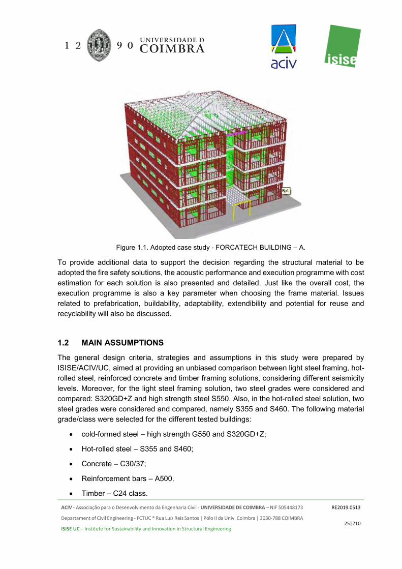
The purpose of this study is to design a reference building and compare the resulting structural solutions for subsequent life-cycle assessment in the framework of the ISO standards ISO 14040 and 14044 and the CEN standards from TC 350. The chosen reference case study is a light steel framed building, the FORCATECH BUILDING-A (Figure 1.1), originally located in Luanda, Angola, modified as appropriate to match European requirements and design practice. The structural design is carried out according to the relevant structural Eurocodes thus ensuring adequate performance levels for each solution. In this report, all comparisons are carried out on the basis of the structural weight of the different materials. Moreover, detailed analyses were conducted to assess the thermal and acoustic performance, fire safety and detailed construction planning and cost estimation for the tested structural systems. It is emphasized that this study is followed by a full life-cycle assessment of all solutions, including life-cycle costing (LCC), whereby a proper cost assessment will be carried out since material costs are not representative of the total cost of a structure.
In order to achieve a representative coverage of Europe, geographically-dependent conditions had to be considered. Hence, besides the reference building located in a non-seismic region, different seismicity levels are also considered, corresponding to medium and high seismicity levels. Also, some variations within some of the structural materials are contemplated, namely the use of high strength steel, for the case of the cold-formed and hot-rolled steel buildings. Moreover, some hybrid solutions are also considered where, for instance, cold-formed steel structures are combined with hot-rolled steel ones in order to reduce the overall impact of the seismic action on the lightweight cold-formed steel structure.
ACIV - Associação para o Desenvolvimento da Engenharia Civil - UNIVERSIDADE DE COIMBRA – NIF 505448173
Departament of Civil Engineering - FCTUC * Rua Luís Reis Santos | Pólo II da Univ. Coimbra | 3030-788 COIMBRA
ISISE UC – Institute for Sustainability and Innovation in Structural Engineering
RE2019.0513
25|210
Figure 1.1. Adopted case study - FORCATECH BUILDING – A.
To provide additional data to support the decision regarding the structural material to be adopted the fire safety solutions, the acoustic performance and execution programme with cost estimation for each solution is also presented and detailed. Just like the overall cost, the execution programme is also a key parameter when choosing the frame material. Issues related to prefabrication, buildability, adaptability, extendibility and potential for reuse and recyclability will also be discussed.
1.2 MAIN ASSUMPTIONS
The general design criteria, strategies and assumptions in this study were prepared by ISISE/ACIV/UC, aimed at providing an unbiased comparison between light steel framing, hot-rolled steel, reinforced concrete and timber framing solutions, considering different seismicity levels. Moreover, for the light steel framing solution, two steel grades were considered and compared: S320GD+Z and high strength steel S550. Also, in the hot-rolled steel solution, two steel grades were considered and compared, namely S355 and S460. The following material grade/class were selected for the different tested buildings:
• cold-formed steel – high strength G550 and S320GD+Z;
• Hot-rolled steel – S355 and S460;
• Concrete – C30/37;
• Reinforcement bars – A500.
• Timber – C24 class.

ACIV - Associação para o Desenvolvimento da Engenharia Civil - UNIVERSIDADE DE COIMBRA – NIF 505448173
Departament of Civil Engineering - FCTUC * Rua Luís Reis Santos | Pólo II da Univ. Coimbra | 3030-788 COIMBRA
ISISE UC – Institute for Sustainability and Innovation in Structural Engineering
RE2019.0513
26|210
Regarding concrete, a specific mix was assumed to provide additional details regarding material consumption. In Table 1.1 some details of the involved materials are presented.
Table 1.1. The density of different materials used in the concrete mix. Materials used in the mix Density - 𝝆 [𝒌𝒈 𝒎𝟑]⁄
Cement Type I 32.5R [CEM] 3100 Aggregate 1 (12 to 18 mm) [A1] 2700 Aggregate 2 (5 to 12 mm) [A2] 2700
Sand (S) 2700 Filler [F] 2700
Fine sand (FS) 2600 Plasticizer (SP) 1030
Water (W) 1000
The considered concrete mix is presented in Table 1.2. In the estimation of all quantities, for the different studied buildings, a waste of 5% was considered.
Table 1.2. The composition of the concrete mix considered. CEM [kg] SP [kg] A1 [kg] A2 [kg] S [kg] FS [kg] F [kg] W/C
C30/37 400 11.6 600 321 470 230 200 0.4
The designs were based on the relevant Eurocodes taking into account the site-specific location for the building, to determine appropriate design loads and ultimately the bill of materials. The following locations were considered:
• Bucharest, Romania – High seismicity zone;
• Faro, Portugal – Medium seismicity zone;
The scope of this study includes the structural framing, passive fire protection materials where applicable and foundations. The design did not include details for all connections or similar items. To estimate the material weights, allowances based on typical conditions and on some details assessed in this study were considered. Within this framework, four different structural solutions were modelled, representing the most common building materials, namely, cold-formed steel, hot-rolled steel, reinforced concrete and timber. For each structural system, different seismicity scenarios will be considered. Based on the same architectural layout 3D structural modelling and analysis have been performed by SAP2000. In this study, the bill of materials for each structural solution was determined, providing data related to the competitiveness of each material for the structural framing for residential buildings. The competitiveness was assessed basically in terms of the overall weight estimation and then in terms of the construction durations.
As a global overview, a summary of the construction options tested is presented in Table 1.3. Each structural solution will be further detailed in Chapter 3.

ACIV - Associação para o Desenvolvimento da Engenharia Civil - UNIVERSIDADE DE COIMBRA – NIF 505448173
Departament of Civil Engineering - FCTUC * Rua Luís Reis Santos | Pólo II da Univ. Coimbra | 3030-788 COIMBRA
ISISE UC – Institute for Sustainability and Innovation in Structural Engineering
RE2019.0513
27|210
Table 1.3. Summary of the construction options tested.
Option Floor System Framing Lateral load-resisting system
Light Steel Framing
Composite slab with steel deck (80 mm)
Cold-formed steel wall panels and CFS truss girders + Hot-rolled
steel profiles
CFS wall panels and hot-rolled steel braced frame
Hot-Rolled Steel Framing
Composite slab with steel deck (140 mm)
Hot-rolled steel sections
Moment resisting frames
Reinforced Concrete
Flat slab (180 or 200 mm)
Reinforced concrete beams and columns
Moment resisting frames and shear walls
Timber
Composite slab with timber panel and
reinforced concrete (80 mm)
LVL sections Plywood or CLT shear walls in
both directions + reinforced concrete shear walls
Reinforced Concrete Shear
Walls
Reinforced concrete flat slabs (140 mm)
Reinforced concrete shear walls (130 mm)
Reinforced concrete shear walls (130 mm)
For the foundations, different solutions were also considered for the different types of buildings as follows:
• raft foundation with strengthening protruding beams – Cold-Formed Steel and Timber buildings;
• Isolated pad foundations with equilibrium beams and suspended ground floor – Hot-Rolled Steel and Reinforced Concrete buildings;
Cladding solutions are also proposed for both wall facades and internal partitioning, considering the different type of use of each compartment in the building and also different climatic areas and different levels of performance. The proposed solutions are versatile and consequently may be used in all tested buildings. In Chapter 3 the assumptions considered are presented and in Annex A the specific range of products is detailed.
In what concerns the acoustic study presented in the scope of this report, the main objective is the proposal of acoustic conditioning solutions, which are determinant so that the building presents adequate acoustic performance according to regulations, but also takes into account the constraints related to the other engineering projects, namely Architecture, Stability and Technical Installations. The nomenclature and definition of the used technical terms generally correspond to the applicable standardization (International Standards), in particular EN ISO 10140 (parts 1,2, 3, 4 and 5); ISO 16283 (parts 1,2 and 3); ISO 717 (parts 1 and 2); ISO 3382 (part 2); and EN 12354 (parts 1 and 2) [1-12].

ACIV - Associação para o Desenvolvimento da Engenharia Civil - UNIVERSIDADE DE COIMBRA – NIF 505448173
Departament of Civil Engineering - FCTUC * Rua Luís Reis Santos | Pólo II da Univ. Coimbra | 3030-788 COIMBRA
ISISE UC – Institute for Sustainability and Innovation in Structural Engineering
RE2019.0513
28|210
In general, all developed countries have specific legislation where they define noise prevention and control policies with a view to safeguarding the health and well-being of populations. On the other hand, with respect to the technical and functional requirements of buildings, there are also regulated acoustic requirements for the buildings and installed technical systems. In the case of residential buildings, treated here in this study, these requirements are essentially of three types, concerning: the insulation to airborne sounds between compartments; the insulation to airborne sounds in relation to the exterior (facades and roofs); the impact noise insulation; and the minimization of noise produced by technical equipment and installations of the building.
In this work, the following calculation principles were generically used: • Calculation of airborne sound insulation, both between interior and exterior
compartments, through the Standard ISO 12354-1, using the software “Acoubat Sound”.
• Calculation of impact sound insulation, following standard ISO 12354-2, using the software “Acoubat Sound”.
• The performance of each constructive element indicated for the various alternatives adopted in the building under consideration, either airborne sound insulation (frequency curves [R, ΔR, Ln; ΔL] and single values [Rw, ΔRw, Ln, ΔLw]), considered in the two previous methodologies, was obtained through the software “INSUL”, with some adjustments taking into account experimental results obtained in laboratory measurements, for similar solutions. In specific cases, when the experimental results for similar solutions were known, those results were directly considered.
• The single values Rw, ΔRw and the spectral adaptation terms C and Ctr were determined according to ISO-717-1. The single values Ln,w and ΔLw and the spectral adaptation term CI were determined according to ISO-717-2.
Although the type of requirement does not vary greatly from country to country, the specific used parameters and the corresponding regulatory limits are significantly different. As an example, the required acoustic performance between residential units in several European countries are presented below. Since the acoustic requirements are very variable both within and outside of Europe, the acoustic requirements between residential units of multi-storey buildings in several European countries are listed on the Table 1.4.

ACIV - Associação para o Desenvolvimento da Engenharia Civil - UNIVERSIDADE DE COIMBRA – NIF 505448173
Departament of Civil Engineering - FCTUC * Rua Luís Reis Santos | Pólo II da Univ. Coimbra | 3030-788 COIMBRA
ISISE UC – Institute for Sustainability and Innovation in Structural Engineering
RE2019.0513
29|210
Table 1.4 Typical acoustic performance requirements in European countries (between apartments in a multi-storey building) [13]. Airborne
Sound Insulation
Impact
Sound Insulation
Country Descriptor Req. [dB]
Descriptor Req. [dB]
Austria DnT,w ≥ 55 L’nT,w ≤ 48 Belgium DnT,w ≥ 54 L’nT,w ≤ 58 Bulgaria R’w ≥ 53 L’n,w ≤ 53 Croatia R’w ≥ 52 L’w ≤ 68 Czech Rep. R’w ≥ 53 L’n,w ≤ 55 Denmark R’w ≥ 55 L’n,w ≤ 53 England & Wales
DnT,w + Ctr ≥ 45 L’nT,w ≤ 62
Estonia R’w ≥ 55 L’n,w ≤ 53 Finland R’w ≥ 55 L’n,w ≤ 53 France DnT,w + C ≥ 53 L’nT,w ≤ 58 Germany R’w ≥ 53 (4) L’n,w ≤ 53 Greece R’w ≥ (50) L’n,w ≤ (60) Hungary R’w + C ≥ 51 L’n,w ≤ 55 Iceland R’w ≥ 55 L’n,w ≤ 53 Ireland DnT,w ≥ 53 (4) L’nT,w ≤ 62 Italy R’w ≥ 50 L’n,w ≤ 63 Latvia R’w ≥ 54 L’n,w ≤ 54 Lithuania DnT,w or R’w ≥ 55 L’n,w ≤ 53 Netherlands R’w + C ≥ 52 L’nT,w + CI ≤ 54 Norway R’w ≥ 55 L’n,w ≤ 53 Poland R’w + C ≥ 50 L’n,w ≤ 58 Portugal DnT,w ≥ 50 L’nT,w ≤ 60 Romania R’w ≥ 51 L’n,w ≤ 59 Scotland DnT,w ≥ 56 L’nT,w ≤ 56 Serbia R’w ≥ 52 L’n,w ≤ 68 Slovakia R’w or DnT,w ≥ 53 L’n,w or L’nT,w ≤ 55
Slovenia R’w ≥ 52 L’n,w ≤ 58 Spain DnT,A ≈ DnT,w+ C ≥ 50 L’nT,w ≤ 65
Sweden R’w + C50-3150 ≥ 53 L’n,w + CI,50-2500 ≤ 56 Switzerland DnT,w + C ≥ 52 L’nT,w + CI ≤ 53
As shown in the table, the performance indicators used can also vary between countries, for different levels of performance, and may include the terms for spectral adaptation (C, Ctr and

ACIV - Associação para o Desenvolvimento da Engenharia Civil - UNIVERSIDADE DE COIMBRA – NIF 505448173
Departament of Civil Engineering - FCTUC * Rua Luís Reis Santos | Pólo II da Univ. Coimbra | 3030-788 COIMBRA
ISISE UC – Institute for Sustainability and Innovation in Structural Engineering
RE2019.0513
30|210
CI). The following calculation formulas, which allow converting between different parameters from the presented results, are indicated.
𝐷𝑛,𝑤 = 𝐷𝑛𝑇,𝑤 − 10 ∗ 𝐿𝑜𝑔(0,032𝑉)
𝐷2𝑚,𝑛,𝑤 = 𝐷2𝑚,𝑛𝑇,𝑤 − 10 ∗ 𝐿𝑜𝑔(0,032𝑉)
𝐿′𝑛,𝑤 = 𝐿′𝑛𝑇,𝑤 + 10 ∗ 𝐿𝑜𝑔(0,032𝑉)
𝑅′𝑤 = 𝐷𝑛𝑇,𝑤 − 10 ∗ 𝐿𝑜𝑔 (0,32𝑉
𝑆)
• V – Volume of the receiving space; • S – Area of the partition elements between receiving and emitting spaces.
Based on the requirements of the European countries and taking into account the required minimum requirements, specific acoustic requirements are proposed for the different types of separation elements in the building under consideration. For the case of acoustic performance, due to the very high requirements that exist in some countries (such as Austria or Scotland) three performance levels were considered: "Sufficient", “Good" and “Excellent”. The acoustic assessment presented in this report is based on the requirements presented in Table 1.5.
Table 1.5 Acoustic performance requirements proposed, taking into account the requirements in different European countries, and considering two performance levels.
Emitting compartment
Receiving compartment
Requirements for “Sufficient”
performance level
Requirements for “Good” performance
level
Requirements for “Excellent”
performance level
Compartment of a different
apartment
Bedroom or living room of adjacent
apartment
DnT,w ≥ 50 dB L’nT,w ≤ 60 dB
DnT,w ≥ 55 dB L’nT,w ≤ 52 dB
DnT,w ≥ 60 dB L’nT,w ≤ 46 dB
Common public hall or access
communal stairway
Living room of adjacent
apartment
DnT,w ≥ 48 dB L’nT,w ≤ 60 dB
DnT,w ≥ 51 dB L’nT,w ≤ 55 dB
DnT,w ≥ 54 dB L’nT,w ≤ 48 dB
Common public hall or access
communal stairway
Bedroom of adjacent
apartment
DnT,w ≥ 50 dB L’nT,w ≤ 60 dB
DnT,w ≥ 54 dB L’nT,w ≤ 52 dB
DnT,w ≥ 58 dB L’nT,w ≤ 46 dB
Bedroom, living room and kitchen
Bedroom or living room from the
same apartment
DnT,w ≥ 38 dB L’nT,w ≤ 70 dB
DnT,w ≥ 45 dB L’nT,w ≤ 65 dB
DnT,w ≥ 50 dB L’nT,w ≤ 60 dB
Exterior Bedroom, living room or kitchen
D2m,nT,w + Ctr ≥ 33 dB
D2m,nT,w + Ctr ≥ 38 dB
D2m,nT,w + Ctr ≥ 42 dB
Exterior Kitchen D2m,nT,w + Ctr ≥ 30 dB
D2m,nT,w + Ctr ≥ 35 dB
D2m,nT,w + Ctr ≥ 40 dB

ACIV - Associação para o Desenvolvimento da Engenharia Civil - UNIVERSIDADE DE COIMBRA – NIF 505448173
Departament of Civil Engineering - FCTUC * Rua Luís Reis Santos | Pólo II da Univ. Coimbra | 3030-788 COIMBRA
ISISE UC – Institute for Sustainability and Innovation in Structural Engineering
RE2019.0513
31|210
It should be noted that, for countries with more demanding requirements, some of the solutions studied, and here classified as "Sufficient", may not be viable to fulfil the required performance. This can be particularly important in what concerns the most demanding situation, which corresponds to the separation between independent fractions of dwellings. It should also be stated that the parameters used in this report correspond to those most commonly used.

ACIV - Associação para o Desenvolvimento da Engenharia Civil - UNIVERSIDADE DE COIMBRA – NIF 505448173
Departament of Civil Engineering - FCTUC * Rua Luís Reis Santos | Pólo II da Univ. Coimbra | 3030-788 COIMBRA
ISISE UC – Institute for Sustainability and Innovation in Structural Engineering
RE2019.0513
32|210
2. CASE STUDY – FORCATECH BUILDING - A
The reference case consists of a four-storey residential building, the FORCATECH BUILDING – A, located in Luanda, Angola, with a footprint of approximately 364 m2, fabricated with cold-formed steel and a hot-rolled steel core for the stairs area. Hence, this is a hybrid building, combining both cold-formed steel and hot-rolled steel structural materials. The building comprises four two-bedrooms apartments per each floor level, an interior hall and stairs. In the original building, no elevators were considered. The reference case was located in Luanda, Angola, and regarding the seismic data, the corresponding importance factor (I) is equal to 1 according to IBC 2009 [14]. The structure was designed to withstand gravity loading (self-weight plus imposed) and the predominant wind loads. The total height of the building is 15.19 m with a 3.2 m storey height. The clear finished floor to ceiling height is 2.6 m. The building used a panellised system, comprising load bearing walls distributed in both directions and a floor system comprising truss beams and composite floor with profiled steel sheets and concrete (minimum concrete strength of fc=20 MPa according to ACI 318-05 code), corresponding to C20/25.
A small change was introduced to the reference case, allowing for the incorporation of two elevators, fulfilling European requirements for this type of buildings. Moreover, for all tested solutions, it was assumed a flat roof. However, no changes were introduced to the overall dimensions of the building. In Figure 2.1, the original groundfloor footprints for the original case and for the modified building are depicted.
The most relevant physical characteristics are detailed in Table 2.1.
Table 2.1. Relevant physical characteristics. Building width 19.996 m Building length 17.750 m
Wall height 3.2 m Wall stud spacing (LBW) 0.406 m
Wall stud spacing (NLBW) 0.610 m Floor joist spacing 0.406 m

ACIV - Associação para o Desenvolvimento da Engenharia Civil - UNIVERSIDADE DE COIMBRA – NIF 505448173
Departament of Civil Engineering - FCTUC * Rua Luís Reis Santos | Pólo II da Univ. Coimbra | 3030-788 COIMBRA
ISISE UC – Institute for Sustainability and Innovation in Structural Engineering
RE2019.0513
33|210
Figure 2.1. Comparison between the original and modified ground floor configuration.
The building consisted of wall framing solution made of high strength cold-formed steel (G550). The external and internal load bearing walls consisted of 150×41×11 studs with 1.15 mm thick and 12 mm or 9 mm fiber cement boards on each side for external and internal walls, respectively. Cold-formed steel straps were used as cross-bracing for the wall panels. To fix the load bearing and non-load bearing walls, anchor bolts and Simpson holdown devices were used as depicted in Figure 2.2. It is worth mentioning that double studs were used at each of the holdown device location (Figure 2.2).
The floor framing comprises truss joists spaced at 0.406 m and aligned with the load bearing wall panels. The floor joists were 300 mm deep and fabricated with lipped channels 89×41×11 profiles with a thickness of 1.15 mm. The composite slab was 80 mm thick (Figure 2.3) made of normal strength concrete.

ACIV - Associação para o Desenvolvimento da Engenharia Civil - UNIVERSIDADE DE COIMBRA – NIF 505448173
Departament of Civil Engineering - FCTUC * Rua Luís Reis Santos | Pólo II da Univ. Coimbra | 3030-788 COIMBRA
ISISE UC – Institute for Sustainability and Innovation in Structural Engineering
RE2019.0513
34|210
Figure 2.2. Anchor bolts and Simpson holdown devices.
Figure 2.3. Floor joists and composite floor.
At the entrance of the building and in the stairs zone hot-rolled steel profiles were used. In order to accommodate the elevators in the modified version of the building, hot-rolled steel frames were also considered in that area (Figure 2.1).

ACIV - Associação para o Desenvolvimento da Engenharia Civil - UNIVERSIDADE DE COIMBRA – NIF 505448173
Departament of Civil Engineering - FCTUC * Rua Luís Reis Santos | Pólo II da Univ. Coimbra | 3030-788 COIMBRA
ISISE UC – Institute for Sustainability and Innovation in Structural Engineering
RE2019.0513
35|210
For the foundations, a mat foundation was adopted, considering different thicknesses for the external load bearing walls (perimeter of the concrete slab) and for internal load bearing walls (entrance and stairs area of the building). The minimum height of the concrete slab is 250 mm and the maximum height is 600 mm in the external load bearing walls and 650 mm at the internal load bearing walls. For the external perimeter of the slab, a thickness of 350 mm was considered, whereas for the internal load bearing wall a thickness of 400 mm was adopted. In Figure 2.4 some details are depicted.
Figure 2.4. Details on the foundations for the reference building. a) Raft foundation at an external load
bearing wall. b) Raft foundation at an internal load bearing wall.
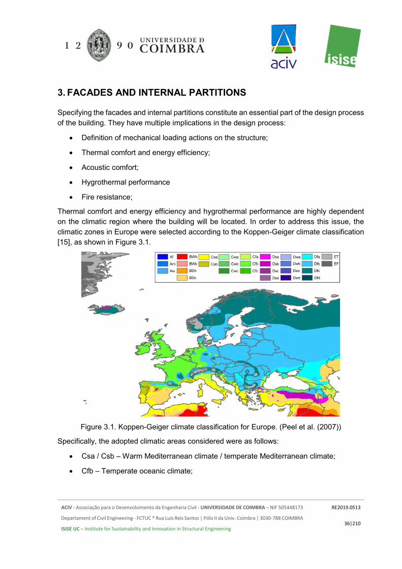
ACIV - Associação para o Desenvolvimento da Engenharia Civil - UNIVERSIDADE DE COIMBRA – NIF 505448173
Departament of Civil Engineering - FCTUC * Rua Luís Reis Santos | Pólo II da Univ. Coimbra | 3030-788 COIMBRA
ISISE UC – Institute for Sustainability and Innovation in Structural Engineering
RE2019.0513
36|210
3. FACADES AND INTERNAL PARTITIONS
Specifying the facades and internal partitions constitute an essential part of the design process of the building. They have multiple implications in the design process:
• Definition of mechanical loading actions on the structure;
• Thermal comfort and energy efficiency;
• Acoustic comfort;
• Hygrothermal performance
• Fire resistance;
Thermal comfort and energy efficiency and hygrothermal performance are highly dependent on the climatic region where the building will be located. In order to address this issue, the climatic zones in Europe were selected according to the Koppen-Geiger climate classification [15], as shown in Figure 3.1.
Figure 3.1. Koppen-Geiger climate classification for Europe. (Peel et al. (2007))
Specifically, the adopted climatic areas considered were as follows:
• Csa / Csb – Warm Mediterranean climate / temperate Mediterranean climate;
• Cfb – Temperate oceanic climate;
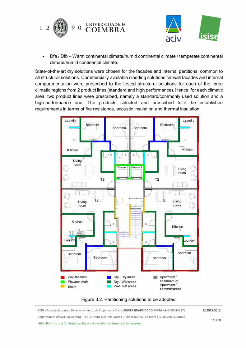
ACIV - Associação para o Desenvolvimento da Engenharia Civil - UNIVERSIDADE DE COIMBRA – NIF 505448173
Departament of Civil Engineering - FCTUC * Rua Luís Reis Santos | Pólo II da Univ. Coimbra | 3030-788 COIMBRA
ISISE UC – Institute for Sustainability and Innovation in Structural Engineering
RE2019.0513
37|210
• Dfa / Dfb – Warm continental climate/humid continental climate / temperate continental climate/humid continental climate.
State-of-the-art dry solutions were chosen for the facades and internal partitions, common to all structural solutions. Commercially available cladding solutions for wall facades and internal compartmentation were prescribed to the tested structural solutions for each of the three climatic regions from 2 product lines (standard and high performance). Hence, for each climatic area, two product lines were prescribed, namely a standard/commonly used solution and a high-performance one. The products selected and prescribed fulfil the established requirements in terms of fire resistance, acoustic insulation and thermal insulation.
Figure 3.2. Partitioning solutions to be adopted.

ACIV - Associação para o Desenvolvimento da Engenharia Civil - UNIVERSIDADE DE COIMBRA – NIF 505448173
Departament of Civil Engineering - FCTUC * Rua Luís Reis Santos | Pólo II da Univ. Coimbra | 3030-788 COIMBRA
ISISE UC – Institute for Sustainability and Innovation in Structural Engineering
RE2019.0513
38|210
Based on the architectural layout of the building, each compartment was analysed, and the most adequate cladding solution was selected, considering two performance levels. In Figure 3.2, the adopted partitioning solutions are detailed for each compartment and external facades. In Annex A all solutions prescribed for wall facades and internal partitioning are prescribed and detailed based on the partitioning requirements defined in Figure 3.2.
It is worth mentioning that for the cold-formed steel and timber buildings the cladding solutions are fastened directly to the structural member (steel studs and joists, and timber posts and beams), excluding the need to use the metal profiles to hold the different panels. The spacing of the steel studs and timber posts is identical to the spacing used for the metal profiles in a cold-formed steel wall assembly. This represents an advantage for these types of buildings since the overall weight associated with the cladding solutions will be lower. The sheathing solutions, specifically for the cold-formed steel and timber buildings also contribute to the lateral resistance of the buildings provided that fixation is adequately prescribed, ensuring a spacing for the fasteners of 100 mm.

ACIV - Associação para o Desenvolvimento da Engenharia Civil - UNIVERSIDADE DE COIMBRA – NIF 505448173
Departament of Civil Engineering - FCTUC * Rua Luís Reis Santos | Pólo II da Univ. Coimbra | 3030-788 COIMBRA
ISISE UC – Institute for Sustainability and Innovation in Structural Engineering
RE2019.0513
39|210
4. CONCEPTUAL DESIGN
4.1 GENERAL CONSIDERATIONS
In this chapter, the conceptual design of the different alternatives considered is briefly summarized. Their structural design incorporates the interaction between the architectural requirements/constraints and the structural engineering capabilities. Hence, based on the initial reference case, the studied structural solutions were designed to ensure the structural functionality conforming to the architectural and structural constraints imposed by the reference case.
The structural model was implemented in software SAP2000 v.20.0.0 [16]. All the beams and columns were modelled with beam elements; the shear walls were modelled with shell elements. The slabs were modelled using a layered thin shell that considers also the steel sheet. At each floor, a rigid diaphragm was considered. The seismic action is included in the analysis by a response spectrum analysis. A static linear analysis was employed considering the fundamental group of combinations.
Concerning seismic design, a crucial issue is to define the design concept and the value of the behaviour factor q. The design concepts, Low-dissipative structural behaviour or Dissipative structural behaviour, are illustrated in Figure 4.1.
Figure 4.1. Design concepts according to EN 1998-1 [17]
In concept a), the action effects may be calculated on the basis of an elastic global analysis neglecting the non-linear behaviour, because a low dissipative structure does not fulfil the conditions to apply a plastic design for predominantly static loading. In this case, the behaviour factor assumed in the calculation must be less than 2. This is the case of the LSF solution and the timber solution, while for the HRS solution and the RC solution dissipative structural behaviour may be considered. In this case, the behaviour factor q depends on the structural

ACIV - Associação para o Desenvolvimento da Engenharia Civil - UNIVERSIDADE DE COIMBRA – NIF 505448173
Departament of Civil Engineering - FCTUC * Rua Luís Reis Santos | Pólo II da Univ. Coimbra | 3030-788 COIMBRA
ISISE UC – Institute for Sustainability and Innovation in Structural Engineering
RE2019.0513
40|210
system according to the relevant ductility classes considered by EC8-1 [17]. For the reinforced concrete solution Ductility Class Medium was selected whereas for the hot-rolled steel solution adopted ductility class was the Ductility Class High. Table 4.1 summarizes the adopted behaviour factors for the 4 structural solutions. Complementary, some additional cases were studied for some structural solutions, namely hot-rolled steel and reinforced concrete. A low seismic location was selected, Coimbra, in Portugal, and different behaviour factors were investigated. For the reinforced concrete the behaviour factor q=3 was also considered and for the hot-rolled steel, the Ductility Class Medium with a behaviour factor of q=4 was also investigated. Specifically, for these cases, only the impact on the superstructure was assessed.
Table 4.1. Behaviour factors q. LSF HRS RC TS
2 (DCL) 6.5 (DCH) 3.9 (DCM) 2
Another very important aspect of this study is the assessment of the overall impact of the adopted structural solution on the foundations of the buildings. Foundations are the major part of the building's substructure. For each structural solution, specific foundation solutions were prescribed and designed. The following types of foundations were adopted for the different structural solutions:
• Cold-formed steel building – Raft foundation incorporating stiffening beams in the perimeter of the building and internal core;
• Hot-rolled steel building – Pad footings with suspended ground floor slab; • Reinforced concrete building – Pad footings with suspended ground floor slab; • Timber building – Raft foundation incorporating stiffening beams in the perimeter of the
building and internal core.
Regarding the fire safety of the studied buildings different and tailored solutions have to be prescribed to each one of the buildings. Firstly, it is necessary to define clearly what are the requirements that the residential building with four storeys must fulfil in terms of load bearing capacity (R), integrity (E) and insulation (I). For the definition of the fire resistance requirements, the Portuguese legislation was adopted. Hence, according to the law, DL n.º 220/2008 [18] and Law n.º 1532/2008 [19] the risk category of the studied building is assessed considering the height of the building and the number of floors below the ground level. The height of the building corresponds to the height of the last floor susceptible to have a permanent use. Consequently, the height of the building for the definition of the category risk is 9.6 m, and according to the Portuguese legislation, the requirement in terms of fire resistance is R 60 for load bearing elements, REI 60 for loadbearing and compartmentation elements and EI 60 com compartmentation elements. The structural fire design is conducted according to the relevant Eurocodes, namely EN 1991-1-2 [20], EN 1992-1-2 [21], EN 1993-1-2 [22], EN
ACIV - Associação para o Desenvolvimento da Engenharia Civil - UNIVERSIDADE DE COIMBRA – NIF 505448173
Departament of Civil Engineering - FCTUC * Rua Luís Reis Santos | Pólo II da Univ. Coimbra | 3030-788 COIMBRA
ISISE UC – Institute for Sustainability and Innovation in Structural Engineering
RE2019.0513
41|210
1994-1-2 [23] and EN 1995-1-2 [24]. It is worth mentioning that for all structural solutions the adopted cladding solutions present inherent fire resistance characteristics both in terms of load bearing capacity (for the cold-formed steel and timber buildings) and compartmentation. The presented solutions in Annex A were tested and certified according to the European standards for fire resistance.
In the following sections, the key aspects of the structural design for each solution are summarized.
4.2 COLD-FORMED STEEL
4.2.1 Description of the structural system I – Hot-rolled steel lateral load resisting system
The structural solution in LSF closely follows the details provided in the reference case. However, since the Forcatech Building was not fitted with lifts neither it was designed for a seismically active area, some necessary structural modifications were implemented. Moreover, and as previously mentioned a flat roof solution was assumed for all buildings. Just like for the reference case, a hybrid solution was adopted for this building, combining both cold-formed steel and hot-rolled steel structural materials.
In the LSF solution, composite slabs were used for the floor system as in the real building. It was assumed that the floors were able to act as a rigid diaphragm, transferring the loads to the vertical load-bearing system. Cold-formed steel truss joists spaced from 406 mm were considered. The height of the truss joists is 400 mm. The composite slab with profiled steel sheeting is 80 mm deep.
The traditional light steel framing structural system comprises two basic types of walls [25]: loadbearing walls, for interior and exterior, and non-loadbearing walls (interior for partition). Structural lipped channel section, "C" steel profiles, are the most used shape. In case of loadbearing walls, the main structure is made by vertical studs spaced usually at 600mm, in line with floor joists, and fastened at each end to wall tracks, that have the function of distributing loads among the studs (see Figure 4.2). Sometimes, supplementary lipped channel profiles are installed to strengthen the stud along the height.

ACIV - Associação para o Desenvolvimento da Engenharia Civil - UNIVERSIDADE DE COIMBRA – NIF 505448173
Departament of Civil Engineering - FCTUC * Rua Luís Reis Santos | Pólo II da Univ. Coimbra | 3030-788 COIMBRA
ISISE UC – Institute for Sustainability and Innovation in Structural Engineering
RE2019.0513
42|210
Figure 4.2. Structural layout for the light-steel framing building [12].
The loadbearing walls should be designed to carry vertical loads transferred from upper floors and roof and they have to resist to horizontal loads (normal and in the plane of the wall) as wind and seismic actions. A typical light-framed shear wall transfers lateral loads, in the plane of the wall, through the mechanically attached sheathing, and into the framing members. The in-plane shear loads are transferred from the wall to the floor framing or foundation along the length of the bottom horizontal member (bottom track). The induced overturning forces are transferred through the vertical boundary members (end studs) and over-turning restraint system (hold-downs) at the ends of the wall. In particular, the ability to resist to horizontal in-plane actions can be achieved by different systems: a) X bracing; b) installing horizontal steel structural sheathing on one or both wall sides; c) fastening structural sheathing boards (OSB) on one or both studs sides, d) mixed solution a-b-c (see Figure 4.3). In particular, structural sheathings have to be installed with the long direction parallel to the studs and have to cover the full height.
Figure 4.3. Structural layout for the light-steel framing building [25].
Wall thickness can be varied to meet the structural and insulation requirements of the building. Exterior rigid insulation is applied to the walls to minimize thermal bridging and comply with building code requirements. The result is a sandwich construction where each panel can undertake perpendicular pressure on its surface as well as horizontal in-plane loads. The internal wall cavity is ideal for inserting cables, pipes and make easy to add equipment.

ACIV - Associação para o Desenvolvimento da Engenharia Civil - UNIVERSIDADE DE COIMBRA – NIF 505448173
Departament of Civil Engineering - FCTUC * Rua Luís Reis Santos | Pólo II da Univ. Coimbra | 3030-788 COIMBRA
ISISE UC – Institute for Sustainability and Innovation in Structural Engineering
RE2019.0513
43|210
Hence, the load bearing system wall system is executed with cold-formed steel studs in order to assure the building resistance against vertical loads, as well as wind and seismic actions. In addition, steel bracings with steel straps for the diagonals were used to achieve appropriate in-plane resistance. The cold-formed steel load bearing wall panels are fixed using anchor bolts and Simpson connectors preventing up-lift of the walls.
The structural layout is shown in Figure 4.4. Moreover, hot-rolled steel moment resisting frames (painted in red in Figure 4.4) located on axes 4-6, B and F were considered in order to provide an inner rigid core for the lifts and the stairs and also to provide additional stiffness for the seismic action. Hence, a major part of the horizontal loads is resisted by these frames allowing for a lighter cold-form steel solution. For the seismic design of the structure, the moment resisting frames are assumed as Ductility Class Low with a behaviour factor q=2.
Figure 4.4. Structural layout for the light-steel framing building.

ACIV - Associação para o Desenvolvimento da Engenharia Civil - UNIVERSIDADE DE COIMBRA – NIF 505448173
Departament of Civil Engineering - FCTUC * Rua Luís Reis Santos | Pólo II da Univ. Coimbra | 3030-788 COIMBRA
ISISE UC – Institute for Sustainability and Innovation in Structural Engineering
RE2019.0513
44|210
4.2.2 Description of the structural system II – Reinforced concrete lateral load resisting system
Complementary, an additional alternative was studied for the CFS building. Instead of using a hot-rolled steel core and strengthening frames, a reinforced concrete core and strengthening reinforced concrete shear walls were considered. Hence, in this situation the lateral loading resisting system was the RC core and RC strengthening shear walls in specific locations of the envelope walls of the CFS building (Figure 4.5). Hence, and has previously assumed for the main solutions tested the CFS load bearing walls were designed to resist mainly the gravity loading.
Figure 4.5. Structural layout for the light-steel framing building with reinforced concrete shear walls for
the reference scenario.

ACIV - Associação para o Desenvolvimento da Engenharia Civil - UNIVERSIDADE DE COIMBRA – NIF 505448173
Departament of Civil Engineering - FCTUC * Rua Luís Reis Santos | Pólo II da Univ. Coimbra | 3030-788 COIMBRA
ISISE UC – Institute for Sustainability and Innovation in Structural Engineering
RE2019.0513
45|210
4.2.3 Foundations
The overall reduced weight of the cold-formed steel structure allows the use of a shallow reinforced concrete raft foundation. Hence, the forces are transmitted to the soil by means of a reinforced concrete slab. In the perimeter and in the core area of the building a thickening of the slab is prescribed, forming strengthening beams in the more heavily loaded zones. A minimum thickness of 250 mm is necessary for the anchor bolts that are used to fix the load bearing walls to the ground floor slab.
In terms of design the adopted raft foundation, strengthened with protruding beams in the more heavily loaded areas, is designed assuming that the slab spans in two directions and that the beam and slab act as inverted beams and slab floor.
The geotechnical design for raft foundations is conducted according to the section 6 of the EN 1997-1 [26]. For this particular study it was assumed a non-cohesive soil, namely a medium gravel or medium gravel and sand with an allowable bearing pressure of 200 kPa.
4.3 HOT-ROLLED STEEL
4.3.1 Description of the structural system I – Hot-rolled steel moment resisting frames as lateral load resisting system
The second structural solution is a moment-resisting structural system composed of hot-rolled steel sections, which are commonly used in residential and office buildings. A typical plan of the structural layout is shown in Figure 4.6. The structural solution consists of a composite floor system, supported on steel frames. The floors are designed with profiled steel sheeting filled with reinforced concrete. In order to guarantee the composite action, a sufficient number of shear studs connecting the steel sheeting to the beams was considered.
Due to the architectural restrictions, it is not possible to use vertical bracing against lateral loads, for that moment resisting frames in both major directions are considered, namely the frames on axes A, B, F, G, 4 and 6, which are pained in red in Figure 4.6.
For the seismic design of the structure, the moment resisting frames are assumed as Ductility Class High with a behaviour factor of q=6.5 for a moment resisting steel framed structure [14]. A solution considering Ductility Class Medium with a behaviour factor of q=4 was also tested for comparison purposes.

ACIV - Associação para o Desenvolvimento da Engenharia Civil - UNIVERSIDADE DE COIMBRA – NIF 505448173
Departament of Civil Engineering - FCTUC * Rua Luís Reis Santos | Pólo II da Univ. Coimbra | 3030-788 COIMBRA
ISISE UC – Institute for Sustainability and Innovation in Structural Engineering
RE2019.0513
46|210
Figure 4.6. Hot-rolled steel structural layout.
4.3.2 Description of the structural system II – Reinforced concrete core as lateral load resisting system
Complementary, an additional alternative was studied for the HRS building. Instead of using a hot-rolled steel core and moment resisting frames, a reinforced concrete core was adopted. Comparing with the solution presented in 4.3.1 this new version has additional changes in the adopted structural layout. Aiming to further optimize the structural solution, the structural layout was slightly modified, eliminating some columns and increasing the spans of some beams. The new structural layout is depicted in Figure 4.7.
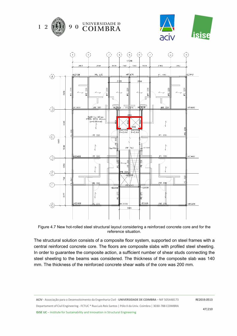
ACIV - Associação para o Desenvolvimento da Engenharia Civil - UNIVERSIDADE DE COIMBRA – NIF 505448173
Departament of Civil Engineering - FCTUC * Rua Luís Reis Santos | Pólo II da Univ. Coimbra | 3030-788 COIMBRA
ISISE UC – Institute for Sustainability and Innovation in Structural Engineering
RE2019.0513
47|210
Figure 4.7 New hot-rolled steel structural layout considering a reinforced concrete core and for the
reference situation.
The structural solution consists of a composite floor system, supported on steel frames with a central reinforced concrete core. The floors are composite slabs with profiled steel sheeting. In order to guarantee the composite action, a sufficient number of shear studs connecting the steel sheeting to the beams was considered. The thickness of the composite slab was 140 mm. The thickness of the reinforced concrete shear walls of the core was 200 mm.
ACIV - Associação para o Desenvolvimento da Engenharia Civil - UNIVERSIDADE DE COIMBRA – NIF 505448173
Departament of Civil Engineering - FCTUC * Rua Luís Reis Santos | Pólo II da Univ. Coimbra | 3030-788 COIMBRA
ISISE UC – Institute for Sustainability and Innovation in Structural Engineering
RE2019.0513
48|210
4.3.3 Foundations
For the hot-rolled steel building, the columns carry larger axial loads than in CFS buildings, at fewer supports. Due to this structural solution, it was assumed a foundation composed of rectangular concrete footings connected with concrete lintels, that are also responsible for supporting ground floor slabs. It is worth noting that the same type of solution was adopted for the foundations of the different investigated situations (HRS core or RC core). As expected, the solution with a HRS core has a higher number of pad footings than the solution with a RC core.
Axial loads from the columns are transmitted to the soil by the rectangular footings. The lintels are designed to resist bending moments from columns, support ground floor slabs and to work as a tie-beam, providing enough stiffness to uniformly transmit the localized actions received from the superstructure to the ground.
The geotechnical design for these foundations is also conducted according to the section 6 of the EN 1997-1 [13]. It was also assumed a non-cohesive soil, namely a medium gravel or medium gravel and sand with an allowable bearing pressure of 200 kPa.
4.4 REINFORCED CONCRETE
4.4.1 Description of the structural system
As a very common solution in practice, a reinforced concrete structure was also considered in this comparative study. The typical plan view is presented in Figure 4.8. The structure consists of reinforced concrete flat slabs supported by square RC columns and shear walls. On the outer perimeter of each floor, RC beams were introduced to release the critical verification of punching shear at the slab edges.
As commonly assumed, the RC flat slab is expected to have sufficient in-plane stiffness in order to provide a rigid floor diaphragm at each floor. This action allows for the smooth transfer of lateral loads to the vertical load bearing system. In the RCS case, the lateral loads are resisted by the core located in between axes 4-6 and B-C; the shear walls on axes 4-6 and F; moment resisting frames along axes A and G; and additionally, the participation of all RC columns was also accounted for in the structural analysis. All members were designed assuming Ductility Class Medium with a behaviour factor q=3.9 for an RC structure with shear walls and RC frames.

ACIV - Associação para o Desenvolvimento da Engenharia Civil - UNIVERSIDADE DE COIMBRA – NIF 505448173
Departament of Civil Engineering - FCTUC * Rua Luís Reis Santos | Pólo II da Univ. Coimbra | 3030-788 COIMBRA
ISISE UC – Institute for Sustainability and Innovation in Structural Engineering
RE2019.0513
49|210
Figure 4.8. Reinforced concrete with flat slabs structural layout.
4.4.2 Foundations
Foundations for RC building are similar than assumed for HRS Buildings. Rectangular footings and lintels have different cross sections, as the loads applied, and spans are different.
For the geotechnical design, the same characteristics were assumed for the soil.

ACIV - Associação para o Desenvolvimento da Engenharia Civil - UNIVERSIDADE DE COIMBRA – NIF 505448173
Departament of Civil Engineering - FCTUC * Rua Luís Reis Santos | Pólo II da Univ. Coimbra | 3030-788 COIMBRA
ISISE UC – Institute for Sustainability and Innovation in Structural Engineering
RE2019.0513
50|210
4.5 TIMBER
4.5.1 Description of the structural system
A timber building system can also be considered as a viable alternative for residential buildings and was also in this study. Timber residential buildings are very common in central and northern Europe as well as in the United States. The proposed solution for the timber building comprises a composite timber-concrete floor and a light frame system similar to the one adopted for the cold-formed steel building. Hence, the framing system will comprise timber beam/joists and posts spaced evenly. The structural layout is depicted in Figure 4.9
Figure 4.9. Timber with shear walls structural layout.

ACIV - Associação para o Desenvolvimento da Engenharia Civil - UNIVERSIDADE DE COIMBRA – NIF 505448173
Departament of Civil Engineering - FCTUC * Rua Luís Reis Santos | Pólo II da Univ. Coimbra | 3030-788 COIMBRA
ISISE UC – Institute for Sustainability and Innovation in Structural Engineering
RE2019.0513
51|210
Just as for cold-formed steel structures on the most relevant structural issues is the stabilization against horizontal loading (wind and earthquakes). Due to architectural restraints, the use of diagonal bracing is not considered. Hence, for the timber building a reinforced concrete shear wall or concrete frame system and if needed additional shear walls (using, for example, wood-based panels or gypsum boards) was considered to resist horizontal loads.
4.5.2 Foundations
Foundations for the timber building are similar than assumed for CFS Buildings, as the reactions on supports have the same magnitude. However, for the concrete core, rectangular footings were included, as the reaction forces on the walls are higher.
For the geotechnical design, the same characteristics were assumed for the soil.
4.6 REINFORCED CONCRETE SHEAR WALL SYSTEM
4.6.1 Description of the structural system
The reinforced concrete shear wall building is an additional solution tested in the scope of this study. This is a cast-in-situ reinforced concrete solution that has been widely used in buildings regular in plan and in elevation for residential use and in seismic regions. It is recognized as an industrialized building system using tailored steel formwork solutions that can be reused multiple times. Meshed reinforcement is used and in specific locations where strengthening is needed ordinary reinforcement bars are used. The lateral and gravity load-resisting system comprises reinforced concrete shear walls and reinforced concrete slabs, where the shear walls resist both the gravity loading and the lateral loading. Specifically, for the 4 storey residential building the adopted wall thickness was 130 mm and the slab thickness was 140 mm. The reinforced concrete shear walls of the building are continuous throughout the building height.
This type of structural solution is usually characterized by reduced construction times since it is possible to erect one floor level in about one week using cast-in-situ concrete and the large formwork panels. Due to the industrialized construction process the erection and dismantling of the formworks is fast. This is usually a very strong, rigid and durable solution with low maintenance costs for the structural part. However, this type of solution is not future proof since they may present severe limitations in terms of re-adaptation, reshaping and reuse. Moreover, this may not be a very competitive solution in terms of sustainability, since its recyclability potential may be reduced.
The building, considering the reinforced concrete shear wall structural solution was designed for the reference location (with no seismic action) and for the high seismic location (Bucharest).

ACIV - Associação para o Desenvolvimento da Engenharia Civil - UNIVERSIDADE DE COIMBRA – NIF 505448173
Departament of Civil Engineering - FCTUC * Rua Luís Reis Santos | Pólo II da Univ. Coimbra | 3030-788 COIMBRA
ISISE UC – Institute for Sustainability and Innovation in Structural Engineering
RE2019.0513
52|210
All shear walls were designed assuming Ductility Class Medium with a behaviour factor q=3.6 for an RC structure with shear walls.
4.6.2 Structural fire design
Just like it was previously mentioned for the traditional reinforced concrete framing solution, this new solution has an inherent good structural fire resistance, both in terms of load bearing capacity, integrity and insulation, hence if the required reinforcement coverings are met no additional protection is needed for the designed solution. When comparing with the RC framing solution there is no need to prescribe the complete Saint-Gobain compartmentation solutions. Specifically, for this solution there is no need to use fire gypsum boards. This can be an advantage in terms of costs and construction planning.
4.6.3 Foundations
Usually, for this type of building two main types of foundations are prescribed, namely strip or mat foundations. Due to the floor plan area and internal distribution of shear walls it was decided to use a mat foundation.
4.7 SUMMARY
The structural solutions presented in the previous sections were designed in accordance with the Structural Eurocodes. The loads are determined in accordance with EN 1991 [28] for the gravity loads and EN 1998-1 [4] for the seismic action. Additional information can be consulted in Annex B of this document. The design of the studied structural solutions is performed following the recommendations of:
• EN 1990 for the basis of structural design [29];
• EN 1991-1 for the definition of the actions on structures [28];
• EN 1992-1-1 for the design of reinforced concrete structures [30];
• EN 1992-1-2 for the structural fire design of concrete structures [21];
• EN 1993-1-1 for the design of the hot-rolled steel solution [31];
• EN 1993-1-3 for the design of the cold-formed structure [32];
• EN 1993-1-2 for the structural fire design of steel structures [22];
• EN 1994-1-1 for the structural design of composite structural members [33];
• EN 1994-1-2 for the structural fire design of composite structural elements [23];
• EN 1995-1-1 for the timber structure [34];

ACIV - Associação para o Desenvolvimento da Engenharia Civil - UNIVERSIDADE DE COIMBRA – NIF 505448173
Departament of Civil Engineering - FCTUC * Rua Luís Reis Santos | Pólo II da Univ. Coimbra | 3030-788 COIMBRA
ISISE UC – Institute for Sustainability and Innovation in Structural Engineering
RE2019.0513
53|210
• EN 1995-1-2 for the structural fire design of timber structures [24];
• EN 1997-1-1 for the geotechnical design [26];
• EN 1998-1-1 (CEN, 2004) for the design of structures under seismic action [17];
• EN 1998-5 for the design of structures for earthquake resistance, namely foundations [35].
As a major objective here, the optimum dimensions for each structural solution were sought. Nevertheless, the specifics of the different materials were taken into account as they are usually applied in practice.
Each structure was designed assuming the three different levels of seismic action considered in this study, namely no seismic action, low, medium and high seismic action.

ACIV - Associação para o Desenvolvimento da Engenharia Civil - UNIVERSIDADE DE COIMBRA – NIF 505448173
Departament of Civil Engineering - FCTUC * Rua Luís Reis Santos | Pólo II da Univ. Coimbra | 3030-788 COIMBRA
ISISE UC – Institute for Sustainability and Innovation in Structural Engineering
RE2019.0513
54|210
5. COMPARATIVE STUDY
5.1 BILL OF MATERIALS
In the following, the summary of the results obtained for the various structural solutions is presented. They are presented as a Bill of Materials (BoM). The comparison is based solely on the load bearing members, such as columns, beams, walls, floor systems, roof materials and foundations. The BoM does not include non-structural items such as internal finishes, doors, windows, etc, as their quantities do not vary between the cases and are not influenced by loads applied to the structure.
The overall weight of the buildings was grouped into different categories, namely, superstructure, foundations, roof and floor, allowing for a clearer comparison between all tested solutions.
The structural area per floor is approximately 364 m2.
Greater attention is paid to how the light steel framing solution compares to the more traditional structural solutions such as hot-rolled steel, reinforced concrete timber and reinforced concrete shear walls system. In the following sub-sections, a brief summary of the results obtained for each alternative is presented.
5.1.1 Light-steel framing solution
The structural analysis was based on the conceptual design presented in Section 4.2. For the other cases studied (medium and high seismic zones), the concrete slab and steel deck weight were not affected. The initial case studies comprised the previously described solutions where different seismicity levels were considered. For these particular situations a hybrid solution was considered, where the hot-rolled steel frames were designed to resist the lateral loading and the cold-formed steel load-bearing elements were designed to resist gravity loading. Additionally, to further expand the study the original lateral force resisting system was replaced by a reinforced concrete one.
In order to have a similar basis of comparison, the quantities are divided into the following categories:
• Cold-formed steel: includes the quantities of all cold-formed profiles needed for the load-bearing system (vertical and horizontal)
• Hot-rolled steel: includes the quantities of the hot-rolled profiles required for the moment resisting frames;
• Concrete: includes the concrete for the composite slabs at each floor and for the foundations and in some investigated cases for the core;
• Reinforcement: includes the reinforcement used in the foundations;

ACIV - Associação para o Desenvolvimento da Engenharia Civil - UNIVERSIDADE DE COIMBRA – NIF 505448173
Departament of Civil Engineering - FCTUC * Rua Luís Reis Santos | Pólo II da Univ. Coimbra | 3030-788 COIMBRA
ISISE UC – Institute for Sustainability and Innovation in Structural Engineering
RE2019.0513
55|210
• Steel deck: includes the quantity of steel sheeting required for the composite slabs at each floor.
Table 5.1 summarizes the BoM per material for the CFS solution with high strength steel (G550) and hot-rolled steel (HRS) core and strengthening frames for the all seismicity level cases studied considering the initial modifications to meet European requirements. The differences to the reference case are due to the consideration of the seismic action in this comparison.
Table 5.1. Bill of structural materials – cold-formed steel solution (G550) with HRS core.
Category Seismicity Level Reference Medium Seismic High Seismic
Cold-Formed Steel 45.5 55.2 55.2 Hot-Rolled Steel 6.4 12.3 15.5 Concrete (slabs) 226.1 226.1 226.1
Reinforcement (slabs) 6.1 6.1 6.1 Concrete (foundations) 296.3 296.3 296.3
Reinforcement (foundations) 8.9 8.9 8.9 Steel Deck 12.9 12.9 12.9 Simpson 0.6 0.8 0.8
Total 602.8 618.6 621.8
In Table 5.2 the BoM for the CFS solution with high strength steel and reinforced concrete core is detailed. Comparing the obtained results, it is clear that the use of a reinforced concrete core did not significantly influence the overall weight of the CFS part of the building. Comparing the overall weight, as expected a significant increase was observed of about 90 ton.
Table 5.2. Bill of structural materials – cold-formed steel solution (G550) with RC core.
Category Seismicity Level Reference High Seismic
Cold-Formed Steel 44.41 55.2 Hot-Rolled Steel 1.61 1.61 Concrete (slabs) 226.1 226.1
Reinforcement (slabs) 6.1 6.1 Concrete (foundations) 296.3 296.3
Reinforcement (foundations) 8.9 8.9 Concrete (core) 91.5 117.2
Reinforcement (core) 5.1 8.8 Steel Deck 12.9 12.9 Simpson 0.6 0.8
Total [ton] 693.5 733.9

ACIV - Associação para o Desenvolvimento da Engenharia Civil - UNIVERSIDADE DE COIMBRA – NIF 505448173
Departament of Civil Engineering - FCTUC * Rua Luís Reis Santos | Pólo II da Univ. Coimbra | 3030-788 COIMBRA
ISISE UC – Institute for Sustainability and Innovation in Structural Engineering
RE2019.0513
56|210
Table 5.3 summarizes the BoM per group (superstructure, foundation, floors, roof) for the CFS solution for all seismicity levels tested.
Table 5.3. Bill of structural materials (ton) according to the defined categories – cold-formed steel solution (G550) .
Category Seismicity Level Reference Medium Seismic High Seismic
Superstructure 52.5 68.3 71.5 Foundations 305.2 305.2 305.2
Floors 181.0 181.0 181.0 Roof 64.1 64.1 64.1 Total 602.8 618.6 621.8
In Table 5.4 the bill of materials for the cold-formed steel solution with S320GD+Z steel is presented. Increasing the seismicity level was followed by an increase in the weight of the superstructure. For the cold-formed steel building no modifications were required for the foundations or floors due to the seismic levels considered.
In Table 5.5 the BoM for the cold-formed steel solution with S320GD+Z steel and reinforced concrete core is presented. Comparing with the solution with hot-rolled steel core and strengthening frames there are no significant savings for the CFS part of the building. For the reference case using a reinforced concrete lateral resisting system the observed savings in terms of cold-formed steel consumption was about 1.6 ton. For the high seismic location no savings were observed for the cold-formed steel part. However, the overall weight of the building increased significantly, by about 90 ton, as expected for a solution with reinforced concrete core.
Table 5.4. Bill of structural materials – cold-formed steel solution (S320).
Category Seismicity Level Reference Medium Seismic High Seismic
Cold-Formed Steel 52.5 62.1 62.1 Hot-Rolled Steel 6.4 12.3 15.5 Concrete (slabs) 226.1 226.1 226.1
Reinforcement (slabs) 6.1 6.1 6.1 Concrete (foundations) 296.3 296.3 296.3
Reinforcement (foundations) 8.9 8.9 8.9 Steel Deck 12.9 12.9 12.9 Simpson 0.6 0.8 0.8
Total 609.8 625.5 628.7

ACIV - Associação para o Desenvolvimento da Engenharia Civil - UNIVERSIDADE DE COIMBRA – NIF 505448173
Departament of Civil Engineering - FCTUC * Rua Luís Reis Santos | Pólo II da Univ. Coimbra | 3030-788 COIMBRA
ISISE UC – Institute for Sustainability and Innovation in Structural Engineering
RE2019.0513
57|210
Table 5.5. Bill of structural materials – cold-formed steel solution (S320) with RC core.
Category Seismicity Level Reference [ton] High Seismic [ton]
Cold-Formed Steel 50.9 62.1 Hot-Rolled Steel 1.53 1.53 Concrete (slabs) 226.1 226.1
Reinforcement (slabs) 6.1 6.1 Concrete (foundations) 296.3 296.3
Reinforcement (foundations) 8.9 8.9 Concrete (core) 91.6 117.3
Reinforcement (core) 5.06 8.83 Steel Deck 12.9 12.9 Simpson 0.6 0.8
Total [ton] 699.9 740.6
Analysing the obtained results, it was observed that the adoption of a reinforced concrete core led to an increase in the overall weight of about 15% for both tested steel grades, namely S320GD+Z and G550, when comparing with the original solution with a hot-rolled steel lateral resisting system. Comparing the total weight of the structural system for the tested seismic scenarios (Reference and High Seismic) the weight increase was about 5.8%.
Table 5.6 summarizes the BoM per group (superstructure, foundation, floors, roof) for the CFS solution for all seismicity levels tested for the S320GD+Z steel with the hot-rolled steel core and strengthening frames.
Table 5.6. Bill of structural materials (ton) according to the defined categories – cold-formed steel solution (S320) with hot-rolled steel core and strengthening frames.
Category Seismicity Level Reference Medium Seismic High Seismic
Superstructure 59.4 75.1 78.4 Foundations 305.2 305.2 305.2
Floors 181.0 181.0 181.0 Roof 64.1 64.1 64.1
Total [ton] 609.8 625.5 628.7
The adopted concrete was the C30/37 for both foundations and composite slabs with steel deck. Based on the selected concrete composition (see Table 1.2) it is possible to estimate the quantities for each one of the materials. In Table 5.7 and Table 5.8 the estimated quantities are presented, assuming a 5% waste. The same overall concrete quantity was used for both steel grades considered.

ACIV - Associação para o Desenvolvimento da Engenharia Civil - UNIVERSIDADE DE COIMBRA – NIF 505448173
Departament of Civil Engineering - FCTUC * Rua Luís Reis Santos | Pólo II da Univ. Coimbra | 3030-788 COIMBRA
ISISE UC – Institute for Sustainability and Innovation in Structural Engineering
RE2019.0513
58|210
Table 5.7. Estimated quantities based on the C30/37 concrete composition for the original solutions with hot-rolled steel lateral load resisting system.
Ref [ton] MS [ton] HS [ton] Concrete C30/37 548.5 548.5 548.5
Cement 91.6 91.6 91.6 Plasticizer 2.6 2.6 2.6 Aggregate1 137.5 137.5 137.5 Aggregate2 73.5 73.5 73.5
Sand 107.7 107.7 107.7 Fine Sand 52.7 52.7 52.7
Filler 45.8 45.8 45.8 Water 36.6 36.6 36.6
Table 5.8. Estimated quantities based on the C30/37 concrete composition for the CFS building with reinforced concrete core.
Ref [ton] HS [ton] Concrete C30/37 644.6 671.6
Cement 107.8 112.3 Plasticizer 3.1 3.3 Aggregate1 161.6 168.4 Aggregate2 86.5 90.1
Sand 126.6 131.9 Fine Sand 62.0 64.6
Filler 53.9 56.1 Water 43.1 44.9
As expected, the adoption of a reinforced concrete core had a significant impact in the overall weight of the building and in the reinforced concrete consumption.
5.1.2 Hot-Rolled Solution
The structural analysis was based on the conceptual design presented in Section 4.3. The sizes of the profiles vary depending on the initial assumptions for the loading. For columns, the selected cross-sections ranged from a HEB 200 to a HEB 450. For beams, the selected cross-sections ranged from IPE 220 to IPE 450. For the tested cases the selected steel grades were the S355 and S460. The height of the composite slab is 140 mm.
Additional information regarding all cross-sections used, including its length and number of pieces is available in Annex D for the different seismicity levels.
In order to have a similar basis of comparison, the quantities are divided into the following materials:

ACIV - Associação para o Desenvolvimento da Engenharia Civil - UNIVERSIDADE DE COIMBRA – NIF 505448173
Departament of Civil Engineering - FCTUC * Rua Luís Reis Santos | Pólo II da Univ. Coimbra | 3030-788 COIMBRA
ISISE UC – Institute for Sustainability and Innovation in Structural Engineering
RE2019.0513
59|210
• Hot-rolled steel: includes the quantities of the hot-rolled profiles required for the moment resisting frames;
• Concrete: includes the concrete for the composite slabs at each floor and the concrete of the foundations;
• Reinforcement: includes the reinforcement of the foundations and composite slabs.
• Steel deck: includes the quantity of steel sheeting required for the composite slabs at each floor.
The design did not include details for all connections or similar items.
Table 5.9 summarizes the BoM per material for the HRS solution for the all seismicity levels and for the S355 steel.
Table 5.9. Bill of structure materials - HRS solution (S355).
Material Structural Weight [tons] Ref. MS_q=6.5 HS_q=6.5
Hot-rolled steel 54.7 59.6 64.1 Concrete (Foundations) 365.8 425.8 425.8
Reinforcement (Foundations) 9.2 9.6 9.6 Concrete (slabs) 332.0 332.0 332.0
Reinforcement (slabs) 4.0 4.0 4.0 Steel deck 12.9 12.9 12.9
Total 778.6 843.9 848.4
Analysing the obtained results, the weight increased 8.4% and 8.9%, respectively for the medium and high seismicity levels, when comparing with the reference case. The seismic action had a significant impact not only in the superstructure but also on the substructure. The weight of the hot-rolled steel elements (both gravity and lateral resisting force systems) increased 9.3% and 17.2%, respectively for the medium and high seismicity levels, when comparing with the reference case. For the foundations the total weight increase was 16.1% when comparing with the reference case. The composite slabs were the same for all tested scenarios.
Table 5.10 summarizes the BoM per group (superstructure, foundation, floors, roof) for the HRS solution for all seismicity levels tested.

ACIV - Associação para o Desenvolvimento da Engenharia Civil - UNIVERSIDADE DE COIMBRA – NIF 505448173
Departament of Civil Engineering - FCTUC * Rua Luís Reis Santos | Pólo II da Univ. Coimbra | 3030-788 COIMBRA
ISISE UC – Institute for Sustainability and Innovation in Structural Engineering
RE2019.0513
60|210
Table 5.10. Bill of structural materials according to the defined categories – HRS solution.
Category Structural Weight [tons] Ref. MS_q=4 HS_q=6.5
Superstructure 54.7 59.6 64.1 Foundations 375.0 435.4 435.4
Floors 257.2 257.2 257.2 Roof 91.7 91.7 91.7 Total 778.6 843.9 848.4
As presented in 4.3.2 an alternative solution considering a reinforced concrete core was also tested. This new solution was also tested for the two steel grades already considered. In Table 5.11 the data regarding the HRS building with reinforced concrete core is presented.
Table 5.11. Bill of materials for the structure – HRS solution (S355) with reinforced concrete core.
Material Structural Weight [tons] Ref. HS_q=6.5
Hot-rolled steel 51.75 53.72 Concrete (Foundations) 355.25 411.25
Reinforcement (Foundations) 8.8 10.0 Concrete (Core) 71.3 71.3
Reinforcement (Core) 3.9 5.4 Concrete (slabs) 332.0 332.0
Reinforcement (slabs) 4.0 4.0 Steel deck 12.9 12.9
Total 840 900.6
Table 5.12. Bill of structure materials - HRS solution (S460).
Material Structural Weight [tons] Ref. MS_q=6.5 HS_q=6.5
Hot-rolled steel 48.1 51.7 52.2 Concrete (Foundations) 365.8 425.8 425.8
Reinforcement (Foundations) 9.2 9.6 9.6 Concrete (slabs) 332.0 332.0 332.0
Reinforcement (slabs) 4.0 4.0 4.0 Steel deck 12.9 12.9 12.9
Total 772.0 836.0 836.5
The adoption of a reinforced concrete core led to an increase in the total weight of the building of about 7.8% and 6.2%, respectively for the reference case and for the high seismic scenario for the hot-rolled steel building with S355 steel.
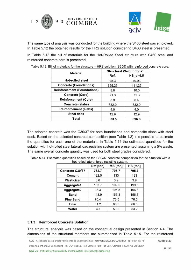
ACIV - Associação para o Desenvolvimento da Engenharia Civil - UNIVERSIDADE DE COIMBRA – NIF 505448173
Departament of Civil Engineering - FCTUC * Rua Luís Reis Santos | Pólo II da Univ. Coimbra | 3030-788 COIMBRA
ISISE UC – Institute for Sustainability and Innovation in Structural Engineering
RE2019.0513
61|210
The same type of analysis was conducted for the building where the S460 steel was employed. In Table 5.12 the obtained results for the HRS solution considering S460 steel is presented.
In Table 5.13 the bill of materials for the Hot-Rolled Steel structure with S460 steel and reinforced concrete core is presented.
Table 5.13. Bill of materials for the structure – HRS solution (S355) with reinforced concrete core.
Material Structural Weight [tons] Ref. HS_q=6.5
Hot-rolled steel 45.3 49.93 Concrete (Foundations) 355.25 411.25
Reinforcement (Foundations) 8.8 10.0 Concrete (Core) 71.3 71.3
Reinforcement (Core) 3.9 5.4 Concrete (slabs) 332.0 332.0
Reinforcement (slabs) 4.0 4.0 Steel deck 12.9 12.9
Total 833.5 896.8
The adopted concrete was the C30/37 for both foundations and composite slabs with steel deck. Based on the selected concrete composition (see Table 1.2) it is possible to estimate the quantities for each one of the materials. In Table 5.14 the estimated quantities for the solution with hot-rolled steel lateral load resisting system are presented, assuming a 5% waste. The same overall concrete quantity was used for both steel grades considered.
Table 5.14. Estimated quantities based on the C30/37 concrete composition for the situation with a hot-rolled lateral force resisting system. Ref [ton] MS [ton] HS [ton]
Concrete C30/37 732.7 795.7 795.7 Cement 122.5 133 133
Plasticizer 3.6 3.9 3.9 Aggregate1 183.7 199.5 199.5 Aggregate2 98.3 106.8 106.8
Sand 143.9 156.3 156.3 Fine Sand 70.4 76.5 76.5
Filler 61.2 66.5 66.5 Water 49 53.2 53.2
5.1.3 Reinforced Concrete Solution
The structural analysis was based on the conceptual design presented in Section 4.4. The dimensions of the structural members are summarized in Table 5.15. For the reinforced
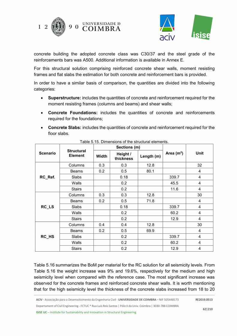
ACIV - Associação para o Desenvolvimento da Engenharia Civil - UNIVERSIDADE DE COIMBRA – NIF 505448173
Departament of Civil Engineering - FCTUC * Rua Luís Reis Santos | Pólo II da Univ. Coimbra | 3030-788 COIMBRA
ISISE UC – Institute for Sustainability and Innovation in Structural Engineering
RE2019.0513
62|210
concrete building the adopted concrete class was C30/37 and the steel grade of the reinforcements bars was A500. Additional information is available in Annex E.
For this structural solution comprising reinforced concrete shear walls, moment resisting frames and flat slabs the estimation for both concrete and reinforcement bars is provided.
In order to have a similar basis of comparison, the quantities are divided into the following categories:
• Superstructure: includes the quantities of concrete and reinforcement required for the moment resisting frames (columns and beams) and shear walls;
• Concrete Foundations: includes the quantities of concrete and reinforcements required for the foundations;
• Concrete Slabs: includes the quantities of concrete and reinforcement required for the floor slabs.
Table 5.15. Dimensions of the structural elements.
Scenario Structural Element
Sections (m) Area (m2) Unit
Width Height / thickness Length (m)
RC_Ref.
Columns 0.3 0.3 12.8 32 Beams 0.2 0.5 80.1 4 Slabs 0.18 339.7 4 Walls 0.2 45.5 4 Stairs 0.2 11.6 4
RC_LS
Columns 0.3 0.3 12.8 30 Beams 0.2 0.5 71.8 4 Slabs 0.18 339.7 4 Walls 0.2 60.2 4 Stairs 0.2 12.9 4
RC_HS
Columns 0.4 0.4 12.8 30 Beams 0.2 0.5 69.9 4 Slabs 0.2 339.7 4 Walls 0.2 60.2 4 Stairs 0.2 12.9 4
Table 5.16 summarizes the BoM per material for the RC solution for all seismicity levels. From Table 5.16 the weight increase was 9% and 19.6%, respectively for the medium and high seismicity level when compared with the reference case. The most significant increase was observed for the concrete frames and reinforced concrete shear walls. It is worth mentioning that for the high seismicity level the thickness of the concrete slabs increased from 18 to 20

ACIV - Associação para o Desenvolvimento da Engenharia Civil - UNIVERSIDADE DE COIMBRA – NIF 505448173
Departament of Civil Engineering - FCTUC * Rua Luís Reis Santos | Pólo II da Univ. Coimbra | 3030-788 COIMBRA
ISISE UC – Institute for Sustainability and Innovation in Structural Engineering
RE2019.0513
63|210
cm. Hence, the weight increase was about 11% for the reinforced concrete flat slabs when comparing the high seismicity level scenario with the medium seismicity and reference scenarios. The impact on the foundations is also worth noting. When considering the seismic action, the total weight of the foundations (concrete plus reinforcement) increased by 24.5%.
Table 5.16. Bill of structure materials - RC solution
Material Structural Weight [tons] Reference Medium Seismic High Seismic
Concrete Frames 205.8 191.5 264.0 Concrete Shear Walls 95.0 125.1 126.3
Concrete (Foundations) 419.5 523.2 523.3 Reinforcement (Foundations) 5.7 6.3 6.3
Concrete (slabs) 584.4 584.4 649.3 Reinforcement (slabs) 18.3 18.3 20.2
Total 1328.7 1448.8 1589.4
Table 5.17. Estimated quantities based on the C30/37 concrete composition. Ref [ton] MS [ton] HS [ton]
Concrete C30/37 1360.8 1486.1 1626.9 Cement 227.5 248.4 271.9
Plasticizer 6.65 7.2 7.9 Aggregate1 341.2 372.6 4077.9 Aggregate2 182.5 199.4 218.3
Sand 267.3 291.9 319.5 FineSand 130.8 142.8 156.4
Filler 113.7 124.2 135.9 Water 91 99.3 108.7
The adopted concrete was the C30/37 for both substructure and superstructure. Based on the selected concrete composition (see Table 1.2) it is possible to estimate the material quantities. In Table 5.17 the estimated quantities are presented, assuming a 5% waste.
5.1.4 Timber solution
For this structural solution, a C24 timber was selected. For the timber posts the cross-section selected was 150 × 150 mm and for the timber joists, the section was 150 × 250 mm. The timber framing was designed to resist the gravity loading, whereas the reinforced concrete walls were designed to resists the lateral forces. For the reference case, the thickness of the shear walls was 15 cm whereas for the medium and high seismicity cases the thickness was 20 cm. The concrete class considered for the shear walls was the C30/37 and the steel grade for the reinforcement bars was A500.

ACIV - Associação para o Desenvolvimento da Engenharia Civil - UNIVERSIDADE DE COIMBRA – NIF 505448173
Departament of Civil Engineering - FCTUC * Rua Luís Reis Santos | Pólo II da Univ. Coimbra | 3030-788 COIMBRA
ISISE UC – Institute for Sustainability and Innovation in Structural Engineering
RE2019.0513
64|210
In Table 5.18 the bill of materials for the timber building considering a high seismicity value is presented.
Table 5.18. Bill of structure materials – timber building.
Category Structure weight [ton] Reference Medium Seismic High Seismic
Timber 69.3 69.3 69.3 Shear Walls 53.1 67.4 68.7
Composite slab 203.2 203.2 203.2 Roof 72.5 72.5 72.5
Foundation 357.5 357.5 357.5 Total 755.6 769.9 771.2
Analysing the obtained results presented in Table 5.18 it is clear that no impact on the timber structure was observed when considering different seismic scenarios. The Timber building was designed using the similar principle adopted for the cold-formed steel building. Hence, the timber framing was designed to resist the gravity loading whereas the reinforced concrete shear walls were designed to resist the lateral forces. This strategy proved to be very efficient since the seismic action had no significant impact on the timber framing system. Considering the high seismicity level led to an increase of about 30% in the weight of the reinforced concrete shear walls when comparing with the reference case (no seismic action). Comparing the overall weight of the timber buildings designed, the increase was about 1.9% and 2.1%, respectively for the medium and high seismicity level, when comparing with the reference case.
The adopted concrete was the C30/37 for both the foundations and composite slabs. Based on the selected concrete composition (see Table 1.2) it is possible to estimate the quantities for each one of the materials. In Table 5.19 the estimated quantities are presented, assuming a 2% waste.
Table 5.19. Estimated quantities based on the C30/37 concrete composition. Ref [ton] MS [ton] HS [ton]
Concrete C30/37 635.6 635.6 614.9 Cement 106.3 106.3 106.3
Plasticizer 3.0 3.0 3.0 Aggregate1 159.4 159.4 159.4 Aggregate2 85.3 85.3 85.3
Sand 124.8 124.8 124.8 FineSand 61.1 61.1 61.1
Filler 53.1 53.1 53.1 Water 42.5 42.5 42.5

ACIV - Associação para o Desenvolvimento da Engenharia Civil - UNIVERSIDADE DE COIMBRA – NIF 505448173
Departament of Civil Engineering - FCTUC * Rua Luís Reis Santos | Pólo II da Univ. Coimbra | 3030-788 COIMBRA
ISISE UC – Institute for Sustainability and Innovation in Structural Engineering
RE2019.0513
65|210
5.1.5 Reinforced concrete shear wall system
The structural analysis was based on the conceptual design presented in section 4.6. The adopted thickness for the shear walls was 130 mm and the thickness of the floor slabs was 140 mm. For the reinforced concrete shear wall building the adopted concrete class was C30/37 and the steel grade of the reinforcements bars was A500.
For this structural solution the estimation for both concrete and reinforcement bars is provided.
In order to have a similar basis of comparison, the quantities are divided into the following categories:
• Superstructure: includes the quantities of concrete and reinforcement required for the shear walls;
• Concrete Foundations: mat foundation includes the quantities of concrete and reinforcements required for the foundations;
• Concrete Slabs: includes the quantities of concrete and reinforcement required for the floor slabs.
Table 5.20 summarizes the BoM per material for the RC shear walls solution for the studied seismicity levels.
From Table 5.16 the weight increase was 9% and 19.6%, respectively for the medium and high seismicity level when compared with the reference case. The most significant increase was observed for the concrete frames and reinforced concrete shear walls. It is worth mentioning that for the high seismicity level the thickness of the concrete slabs increased from 18 to 20 cm. Hence, the weight increase was about 11% for the reinforced concrete flat slabs when comparing the high seismicity level scenario with the medium seismicity and reference scenarios. The impact on the foundations is also worth noting. When considering the seismic action, the total weight of the foundations (concrete plus reinforcement) increased by 24.5%.
Table 5.20. Bill of structure materials – RC shear walls solution
Material Structural Weight [tons] Reference Medium Seismic High Seismic
Concrete Shear Walls 888.5 888.5 888.5 Reinforcement (Shear Walls) 6.125 10.021 10.021
Concrete (Foundations) 273.5 328.0 328.0 Reinforcement (Foundations) 8.54 10.280 10.280
Concrete (slabs) 452.25 452.25 452.25 Reinforcement (slabs) 8.570 8.570 8.570
Total 1637.5 1697.6 1697.6

ACIV - Associação para o Desenvolvimento da Engenharia Civil - UNIVERSIDADE DE COIMBRA – NIF 505448173
Departament of Civil Engineering - FCTUC * Rua Luís Reis Santos | Pólo II da Univ. Coimbra | 3030-788 COIMBRA
ISISE UC – Institute for Sustainability and Innovation in Structural Engineering
RE2019.0513
66|210
The adopted concrete was the C30/37 for both the RC shear walls building. Based on the selected concrete composition (see Table 1.2) it is possible to estimate the quantities for each one of the materials. In Table 5.21 the estimated quantities are presented, assuming a 5% waste.
Table 5.21. Estimated quantities based on the C30/37 concrete composition. Ref [ton] MS [ton] HS [ton]
Concrete C30/37 1694.9 1752.2 1752.2 Cement 283.4 292.9 292.9
Plasticizer 8.2 8.5 8.5 Aggregate1 425.1 439.4 439.4 Aggregate2 227.4 235.1 235.1
Sand 332.9 344.2 344.2 FineSand 162.9 168.4 168.4
Filler 141.6 146.5 146.5 Water 113.3 117.1 117.1
5.1.6 Weight comparison
In summary, a weight comparison for the assessed structural alternatives is proposed. In this section, it is solely based on the weights obtained for the reference cases, i.e. without the consideration of seismic action. Its impact is discussed in a separate paragraph (see Section 5.2).
The comparison, analysis and discussion are conducted on the basis of the results obtained from the structural analysis. The total weight estimated and the total weight per square meter for each structural solution is summarized in Table 5.22 and Table 5.23 and graphically in Figure 5.1. For the estimation of the weight of the materials an area of 1384 m2 was considered.
From the analysis of Figure 5.1 it is clear that the total weight of the reinforced concrete building is 2.21, 2.18, 1.71, 1.72 and 1.76 times (120.7%, 118.2%, 71.4%, 72.15 and 75.8%) higher than the weight of the cold-formed steel (G550 and S320GD+Z), hot-rolled steel (S355 and S460) and timber buildings, respectively. The estimations presented are only for the structural elements of the building.
Cold-formed steel buildings are the lightest, however, it worth mentioning their hybrid character since the lateral force resisting system was mainly based on hot-rolled steel frames or on a reinforced concrete frame.

ACIV - Associação para o Desenvolvimento da Engenharia Civil - UNIVERSIDADE DE COIMBRA – NIF 505448173
Departament of Civil Engineering - FCTUC * Rua Luís Reis Santos | Pólo II da Univ. Coimbra | 3030-788 COIMBRA
ISISE UC – Institute for Sustainability and Innovation in Structural Engineering
RE2019.0513
67|210
Table 5.22. Comparison of total structural materials weight.
Structural solution
Superstructure
Found. [ton]
Slabs Gravitational loads resisting elements
Lateral resisting elements
CFS [ton]
HRS [ton]
RC [ton] T [ton] MRF/shear
walls [ton] Slabs [ton]
Steel Deck [ton]
CFS_Ref_G550I 46 0.5 5.9 305.2 231.2 12.9
CFS_Ref_G550II 44.4 1.6 96.6 305.2 231.2 12.9 CFS_Ref_S320I 52 0.5 5.9 305.2 231.2 12.9 CFS_Ref_S320II 50.9 1.6 96.6 305.2 231.1 12.9 HRS_S355I_Ref 45.4 9.3 375 336.0 12.9 HRS_S355II_Ref 51.7 75.2 364.0 336.0 12.9 HRS_S460I_Ref 39.8 8.3 375 336.0 12.9 HRS_S460II_Ref 45.3 75.2 364.0 336.0 12.9
RC_Ref. 205.8 95.0 425.2 602.7
T_Ref. 69.3 53.1 357.5 275.7
RC_SW_Ref 859.1 271.1 442.7
For the foundations, and once again taking advantage of the reduced weight of the superstructure the lightest ones are the ones for the cold-formed steel buildings. For the reference case, the weight of the foundations of the reinforced concrete building is 39.1%, 13.4% and 18.9% higher than the weight of the foundations for the cold-formed steel, hot-rolled steel and timber buildings.
Figure 5.1. Total weight comparison between the initial structural solutions, for the reference case
(without seismic action).

ACIV - Associação para o Desenvolvimento da Engenharia Civil - UNIVERSIDADE DE COIMBRA – NIF 505448173
Departament of Civil Engineering - FCTUC * Rua Luís Reis Santos | Pólo II da Univ. Coimbra | 3030-788 COIMBRA
ISISE UC – Institute for Sustainability and Innovation in Structural Engineering
RE2019.0513
68|210
In order to further expand the number of possible solutions for the studied building, additional solutions were tested and compared. Specifically, for the reference scenario, the use of a reinforced concrete core for the steel solutions and the use of a reinforced concrete shear walls system were investigated. In Figure 5.2 all studied cases are presented.
Figure 5.2. Total weight comparison between all tested structural solutions, for the reference case
(without seismic action).
As expected and based on the depicted results in Figure 5.2 the heaviest structural solution is the one using reinforced concrete shear walls (RC_SW_Ref). Comparing with reinforced concrete framed solution (RC_Ref) the weight increase was about 23%. However, due to the construction system and despite the weight increase, this solution may present some advantages in terms of execution times since its construction process requires lower periods of time when comparing with the more traditional reinforced concrete framed solution.
It is worth mentioning that for all buildings the overall weight of the floors and foundations represent a significant part of its weight. Consequently, in some of the following comparisons, the different structural categories will be individualized, and the more relevant ones compared, so that the overall impacts on the weight estimations may be clearly assessed. In Figure 5.3 the total weight per square meter is presented for the original solutions.

ACIV - Associação para o Desenvolvimento da Engenharia Civil - UNIVERSIDADE DE COIMBRA – NIF 505448173
Departament of Civil Engineering - FCTUC * Rua Luís Reis Santos | Pólo II da Univ. Coimbra | 3030-788 COIMBRA
ISISE UC – Institute for Sustainability and Innovation in Structural Engineering
RE2019.0513
69|210
Table 5.23. Comparison of structural materials weight per sqm.
Structural solution
Superstructure
Found. [kg/m2]
Slabs Gravitational loads resisting elements
Lateral resisting elements
CFS [kg/m2]
HRS [kg/m2]
RC [kg/m2]
T [kg/m2]
MRF/shear walls [kg/m2]
Slabs [kg/m2]
Steel Deck
[kg/m2]
CFS_Ref._G550I 32.9 0.3 4.3 220.5 167.7 9.3 CFS_Ref._G550II 39.9 1.2 91.5 220.5 167.8 9.3 CFS_Ref._S320I 37.9 0.3 4.3 220.5 167.7 9.3 CFS_Ref._S320II 44.8 1.2 91.1 220.5 167.8 9.3 HRS_S355_RefI 32.8 6.7 270.9 242.8 9.3 HRS_S355_RefII 37.4 54.4 263.0 242.8 9.3 HRS_S460_RefI 28.7 6.0 270.9 242.8 9.3 HRS_S460_RefII 32.7 54.4 263.0 242.8 9.3
RC_Ref. 148.7 68.6 307.2 435.5 T_Ref. 50.1 38.4 258.3 199.2
RC_SW_Ref. 646.4 203.8 333.0
Figure 5.3. Total weight (per sqm) comparison between the initial structural solutions, for the reference
case (without seismic action).
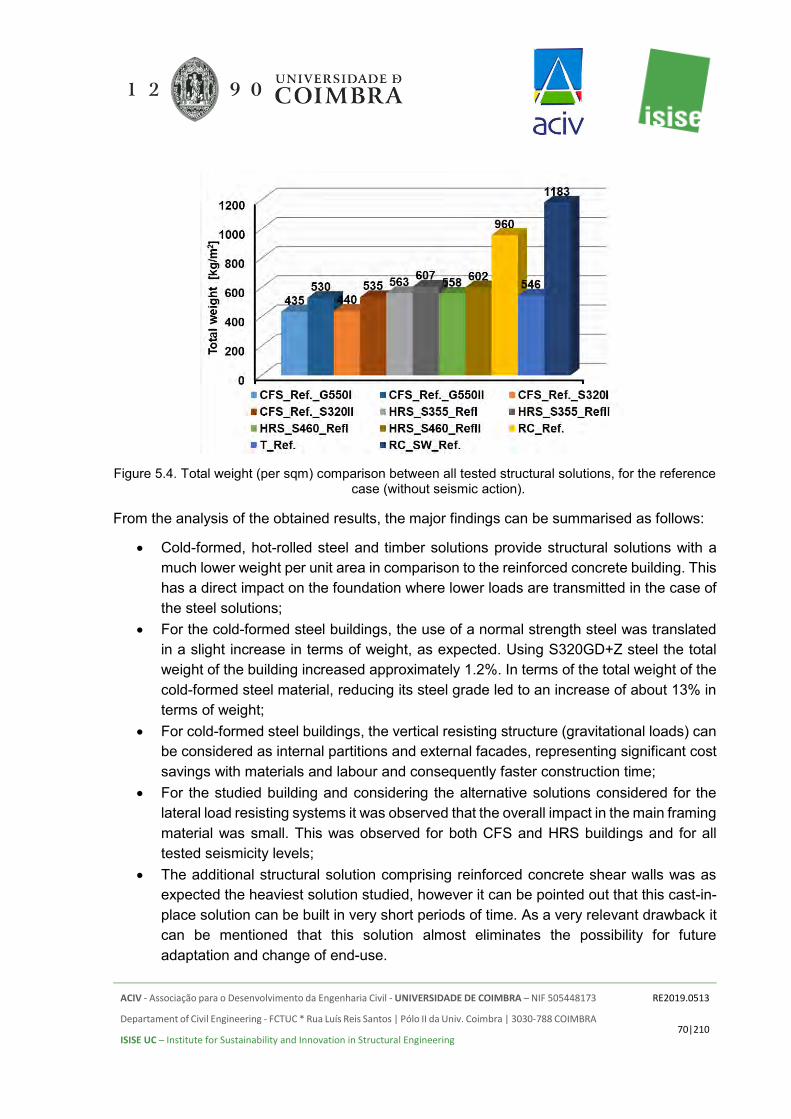
ACIV - Associação para o Desenvolvimento da Engenharia Civil - UNIVERSIDADE DE COIMBRA – NIF 505448173
Departament of Civil Engineering - FCTUC * Rua Luís Reis Santos | Pólo II da Univ. Coimbra | 3030-788 COIMBRA
ISISE UC – Institute for Sustainability and Innovation in Structural Engineering
RE2019.0513
70|210
Figure 5.4. Total weight (per sqm) comparison between all tested structural solutions, for the reference
case (without seismic action).
From the analysis of the obtained results, the major findings can be summarised as follows:
• Cold-formed, hot-rolled steel and timber solutions provide structural solutions with a much lower weight per unit area in comparison to the reinforced concrete building. This has a direct impact on the foundation where lower loads are transmitted in the case of the steel solutions;
• For the cold-formed steel buildings, the use of a normal strength steel was translated in a slight increase in terms of weight, as expected. Using S320GD+Z steel the total weight of the building increased approximately 1.2%. In terms of the total weight of the cold-formed steel material, reducing its steel grade led to an increase of about 13% in terms of weight;
• For cold-formed steel buildings, the vertical resisting structure (gravitational loads) can be considered as internal partitions and external facades, representing significant cost savings with materials and labour and consequently faster construction time;
• For the studied building and considering the alternative solutions considered for the lateral load resisting systems it was observed that the overall impact in the main framing material was small. This was observed for both CFS and HRS buildings and for all tested seismicity levels;
• The additional structural solution comprising reinforced concrete shear walls was as expected the heaviest solution studied, however it can be pointed out that this cast-in-place solution can be built in very short periods of time. As a very relevant drawback it can be mentioned that this solution almost eliminates the possibility for future adaptation and change of end-use.

ACIV - Associação para o Desenvolvimento da Engenharia Civil - UNIVERSIDADE DE COIMBRA – NIF 505448173
Departament of Civil Engineering - FCTUC * Rua Luís Reis Santos | Pólo II da Univ. Coimbra | 3030-788 COIMBRA
ISISE UC – Institute for Sustainability and Innovation in Structural Engineering
RE2019.0513
71|210
5.2 INFLUENCE OF THE SEISMICITY LEVEL
5.2.1 Introduction
In this section, the different seismicity levels are assessed. The different structural solutions are firstly compared separately, which is followed by a global comparison between the various alternatives.
In the assessment, it was assumed that the building is situated in two different locations:
• Medium Seismicity level (MS) – Faro, Portugal • High Seismicity level (HS) – Bucharest, Romania.
In addition, for some cases, a Low Seismicity (LS) location was also considered: Low seismicity level – Coimbra, Portugal. Moreover, different behaviour factors were also considered in this study for the reinforced concrete building (q=3 and q=3.9) and for the hot-rolled steel building (q=4 and q=6.5).
In the previous section, it was shown that the concrete slabs are responsible for more than 80% of the total structural weight. Although this is a major part, it is not affected by the seismic loads. Following the objectives of this section, the weight of the slabs is not included in the comparisons of this section. It is noted that the RC solution has increased the slab width for the HS level.
5.2.2 CFS solution
In Figure 5.5 a comparison is established between the overall weight estimation for the Cold-Formed steel building, considering the high strength steel G550, for the different seismicity levels considered. The materials used are compared. This is a hybrid building, incorporating cold-formed steel strengthened in specific areas by hot-rolled steel frames which resisted the lateral loading (wind and seismic action).
It is clear that the weight of the foundations and slabs/roof is very significant when compared with the weight of the cold-formed steel members. Consequently, in Figure 5.6 only the cold-formed and hot-rolled steel are presented and compared. The hot-rolled steel frames were used to resist the horizontal loading, ensuring that the cold-formed steel structure can resist only the gravity loading.

ACIV - Associação para o Desenvolvimento da Engenharia Civil - UNIVERSIDADE DE COIMBRA – NIF 505448173
Departament of Civil Engineering - FCTUC * Rua Luís Reis Santos | Pólo II da Univ. Coimbra | 3030-788 COIMBRA
ISISE UC – Institute for Sustainability and Innovation in Structural Engineering
RE2019.0513
72|210
Figure 5.5. Total weight comparison between all tested seismic scenarios (G550).
Observing the obtained results, the total weight increase from the reference situation to a medium seismic location was about 2.5%, whereas comparing the reference case with the high seismicity scenario the weight increase was 3.12%. Regarding the hot-rolled steel (lateral resisting frames) the weight increased by 100% when comparing the reference case with the medium seismicity level and 166% when comparing the reference case with the high seismicity level. The results show clearly that the hybrid solution considered is effective and that each framing system is performing correctly and as expected. Based on the results presented in Figure 5.6 the weight of the cold-formed steel structural elements increased approximately 21% when comparing the reference situation with the medium and high seismic scenario. Comparing the medium and high seismicity the impact was only observed in the lateral force resisting elements.
Figure 5.6. The weight of the superstructure for the different seismic scenarios (G550).
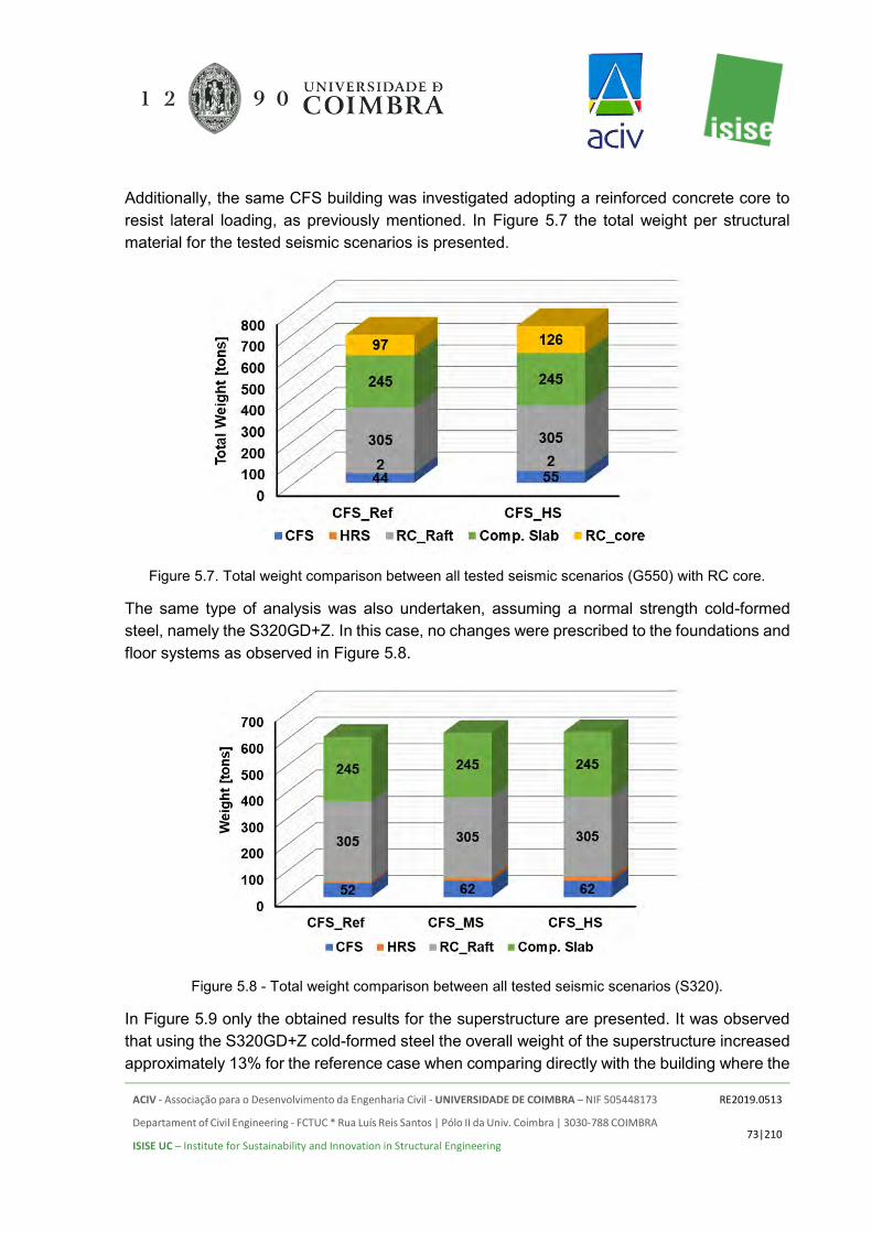
ACIV - Associação para o Desenvolvimento da Engenharia Civil - UNIVERSIDADE DE COIMBRA – NIF 505448173
Departament of Civil Engineering - FCTUC * Rua Luís Reis Santos | Pólo II da Univ. Coimbra | 3030-788 COIMBRA
ISISE UC – Institute for Sustainability and Innovation in Structural Engineering
RE2019.0513
73|210
Additionally, the same CFS building was investigated adopting a reinforced concrete core to resist lateral loading, as previously mentioned. In Figure 5.7 the total weight per structural material for the tested seismic scenarios is presented.
Figure 5.7. Total weight comparison between all tested seismic scenarios (G550) with RC core.
The same type of analysis was also undertaken, assuming a normal strength cold-formed steel, namely the S320GD+Z. In this case, no changes were prescribed to the foundations and floor systems as observed in Figure 5.8.
Figure 5.8 - Total weight comparison between all tested seismic scenarios (S320).
In Figure 5.9 only the obtained results for the superstructure are presented. It was observed that using the S320GD+Z cold-formed steel the overall weight of the superstructure increased approximately 13% for the reference case when comparing directly with the building where the

ACIV - Associação para o Desenvolvimento da Engenharia Civil - UNIVERSIDADE DE COIMBRA – NIF 505448173
Departament of Civil Engineering - FCTUC * Rua Luís Reis Santos | Pólo II da Univ. Coimbra | 3030-788 COIMBRA
ISISE UC – Institute for Sustainability and Innovation in Structural Engineering
RE2019.0513
74|210
high strength G550 steel was used. Establishing a comparison between the different seismicity levels tested it was found that the superstructure weight increased 26.2% and 31.7%, respectively for the medium and high seismicity levels, when compared with the reference case.
Figure 5.9 - Weight of the superstructure for the different seismic scenarios (S320).
From Figure 5.9 the weight increase of the lateral force resisting system is significant when the seismicity level increases. For the medium seismicity level, the weight of the lateral force resisting system increased 92.4% and for the high seismicity level, it has increased by 143.5% when compared with the reference case. From the medium to the high seismicity level no significant weight increase was observed for the cold-formed steel structure. Hence, the hot-rolled steel structure can withstand all the lateral forces and the cold-formed steel resists the gravity loading.
Additionally, the same CFS building was investigated adopting a reinforced concrete core to resist lateral loading, as previously mentioned. In Figure 5.10 the total weight per structural material for the tested seismic scenarios is presented. Adopting a reinforced concrete core as lateral resisting system did not impact significantly the overall weight of the cold-formed steel part of the building.
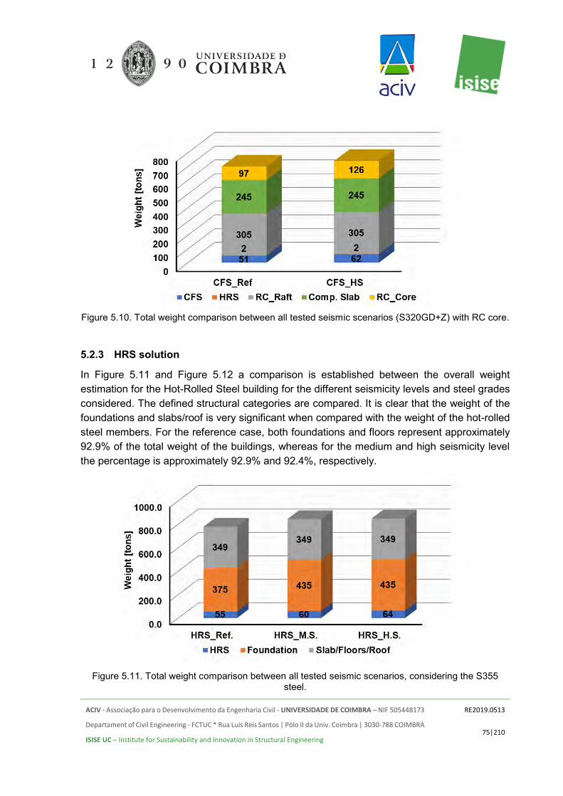
ACIV - Associação para o Desenvolvimento da Engenharia Civil - UNIVERSIDADE DE COIMBRA – NIF 505448173
Departament of Civil Engineering - FCTUC * Rua Luís Reis Santos | Pólo II da Univ. Coimbra | 3030-788 COIMBRA
ISISE UC – Institute for Sustainability and Innovation in Structural Engineering
RE2019.0513
75|210
Figure 5.10. Total weight comparison between all tested seismic scenarios (S320GD+Z) with RC core.
5.2.3 HRS solution
In Figure 5.11 and Figure 5.12 a comparison is established between the overall weight estimation for the Hot-Rolled Steel building for the different seismicity levels and steel grades considered. The defined structural categories are compared. It is clear that the weight of the foundations and slabs/roof is very significant when compared with the weight of the hot-rolled steel members. For the reference case, both foundations and floors represent approximately 92.9% of the total weight of the buildings, whereas for the medium and high seismicity level the percentage is approximately 92.9% and 92.4%, respectively.
Figure 5.11. Total weight comparison between all tested seismic scenarios, considering the S355
steel.

ACIV - Associação para o Desenvolvimento da Engenharia Civil - UNIVERSIDADE DE COIMBRA – NIF 505448173
Departament of Civil Engineering - FCTUC * Rua Luís Reis Santos | Pólo II da Univ. Coimbra | 3030-788 COIMBRA
ISISE UC – Institute for Sustainability and Innovation in Structural Engineering
RE2019.0513
76|210
Figure 5.12. Total weight comparison between all tested seismic scenarios, considering the S460 steel.
To overcome this limitation a new comparison is presented, detailing the hot-rolled steel weight for each tested condition (Figure 5.13). Observing the obtained results, the weight increase is clear with increasing seismicity level. For instance, comparing the reference building (no seismic location) with the same building in a Medium Seismic location (MS) the HRS weight increase was 8.9%, whereas for the High Seismic location (HS) the weight increase was 17.2%.
Figure 5.13. Total weight comparison between tested seismicity levels, considering both S355 and
S460 steels.

ACIV - Associação para o Desenvolvimento da Engenharia Civil - UNIVERSIDADE DE COIMBRA – NIF 505448173
Departament of Civil Engineering - FCTUC * Rua Luís Reis Santos | Pólo II da Univ. Coimbra | 3030-788 COIMBRA
ISISE UC – Institute for Sustainability and Innovation in Structural Engineering
RE2019.0513
77|210
Comparing the results depicted in Figure 5.13, increasing the steel grade led to a reduction of the steel weight used in the superstructure. For the reference case, the reduction was 12.7%, whereas for the medium and high seismicity levels the reduction was 13.3% and 18.75%, respectively.
Complementary, some additional studies were undertaken only considering the S355 steel, focusing mainly on the overall impact of the seismic action on the total weight of the hot-rolled steel superstructure. To do this, an additional seismic location was selected, namely Coimbra, which is a low seismic location, and two behaviour factors were considered, namely q=4 (Ductility Class Medium - DCM) and q=6.5 (Ductility Class High - DCH). In Figure 5.14 the obtained results for the hot-rolled steel superstructure are depicted. Analyzing the obtained results, the weight increase is clear for the hot-rolled steel superstructure with increasing seismicity level. For this specific building, it is clear that considering a DCH may provide some benefits for the high seismicity level, whereas for the low seismicity level the need to consider Class 1 cross-section led to an increase in terms of weight when comparing with the DCM situation.
Figure 5.14. Hot-rolled steel weight comparison for the tested scenarios, considering both DCM and
DCH, with the correspondent behaviour factors q=4 and q=6.5.
In Figure 5.15 and Figure 5.16 the structural weight per square meter for the superstructure are presented. Specifically, the superstructure elements responsible for resisting the lateral loads and the ones responsible for resisting the gravitational loads are individualized.

ACIV - Associação para o Desenvolvimento da Engenharia Civil - UNIVERSIDADE DE COIMBRA – NIF 505448173
Departament of Civil Engineering - FCTUC * Rua Luís Reis Santos | Pólo II da Univ. Coimbra | 3030-788 COIMBRA
ISISE UC – Institute for Sustainability and Innovation in Structural Engineering
RE2019.0513
78|210
Figure 5.15. Weight comparisons for all tested cases – Hot-Rolled Steel building [kg/m2], considering
the S355 steel.
Figure 5.16. Weight comparisons for all tested cases – Hot-Rolled Steel building [kg/m2], considering
the S460 steel
In order to further extend the investigated alternatives for the Hot-Rolled Steel building solution an additional case was considered, as previously mentioned and detailed in section 4.3.2. In this new case the hot-rolled steel core was replaced by a reinforced concrete one. This new solution was tested for both steel grades considered (S355 and S460) and for two scenarios, namely the reference (no seismic action) and high seismic scenario. In Figure 5.17 and Figure 5.18 the BoM per category is presented for both steel grades considered in this study.
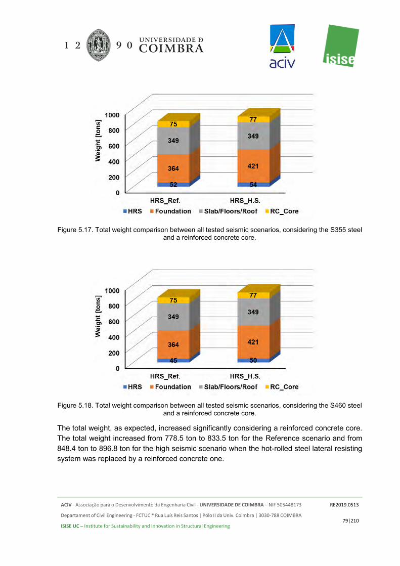
ACIV - Associação para o Desenvolvimento da Engenharia Civil - UNIVERSIDADE DE COIMBRA – NIF 505448173
Departament of Civil Engineering - FCTUC * Rua Luís Reis Santos | Pólo II da Univ. Coimbra | 3030-788 COIMBRA
ISISE UC – Institute for Sustainability and Innovation in Structural Engineering
RE2019.0513
79|210
Figure 5.17. Total weight comparison between all tested seismic scenarios, considering the S355 steel
and a reinforced concrete core.
Figure 5.18. Total weight comparison between all tested seismic scenarios, considering the S460 steel
and a reinforced concrete core.
The total weight, as expected, increased significantly considering a reinforced concrete core. The total weight increased from 778.5 ton to 833.5 ton for the Reference scenario and from 848.4 ton to 896.8 ton for the high seismic scenario when the hot-rolled steel lateral resisting system was replaced by a reinforced concrete one.

ACIV - Associação para o Desenvolvimento da Engenharia Civil - UNIVERSIDADE DE COIMBRA – NIF 505448173
Departament of Civil Engineering - FCTUC * Rua Luís Reis Santos | Pólo II da Univ. Coimbra | 3030-788 COIMBRA
ISISE UC – Institute for Sustainability and Innovation in Structural Engineering
RE2019.0513
80|210
5.2.4 Reinforced concrete solution
In Figure 5.19 a comparison is established between the overall weight estimation for the Reinforced Concrete building for the different seismicity levels considered. The defined structural categories are compared. It is clear that the weight of the slabs/roof is very significant when compared with the weight of the reinforced concrete columns and beams.
Figure 5.19. Total weight comparison between all tested scenarios for the reinforced concrete building.
For the investigated scenarios the foundations and floors represent approximately 77.4%, 78.2% and 75.5% of the total weight, respectively for the reference case, medium seismic and high seismic location. Comparing the obtained results, the building located in a high seismic area weighs approximately 19.6% more than the reinforced concrete building in a non-seismic location.
In Figure 5.20 a comparison is established between all tested solutions for the superstructure and slabs, in order to assess the impact of the considered seismicity levels in the reinforced concrete structure. For the High Seismicity level, the total weight of the slabs also increased since its thickness increased from 18 to 20 cm. The weight increase was approximately 11%.
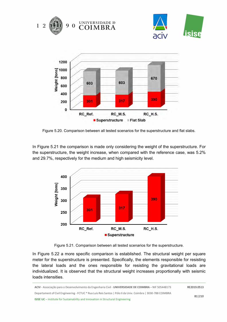
ACIV - Associação para o Desenvolvimento da Engenharia Civil - UNIVERSIDADE DE COIMBRA – NIF 505448173
Departament of Civil Engineering - FCTUC * Rua Luís Reis Santos | Pólo II da Univ. Coimbra | 3030-788 COIMBRA
ISISE UC – Institute for Sustainability and Innovation in Structural Engineering
RE2019.0513
81|210
Figure 5.20. Comparison between all tested scenarios for the superstructure and flat slabs.
In Figure 5.21 the comparison is made only considering the weight of the superstructure. For the superstructure, the weight increase, when compared with the reference case, was 5.2% and 29.7%, respectively for the medium and high seismicity level.
Figure 5.21. Comparison between all tested scenarios for the superstructure.
In Figure 5.22 a more specific comparison is established. The structural weight per square meter for the superstructure is presented. Specifically, the elements responsible for resisting the lateral loads and the ones responsible for resisting the gravitational loads are individualized. It is observed that the structural weight increases proportionally with seismic loads intensities.

ACIV - Associação para o Desenvolvimento da Engenharia Civil - UNIVERSIDADE DE COIMBRA – NIF 505448173
Departament of Civil Engineering - FCTUC * Rua Luís Reis Santos | Pólo II da Univ. Coimbra | 3030-788 COIMBRA
ISISE UC – Institute for Sustainability and Innovation in Structural Engineering
RE2019.0513
82|210
Figure 5.22. Weight comparisons for all tested cases – Reinforced concrete building [kg/m2].
As mentioned earlier, for the HS level, the columns sections and slab thickness increased due to the higher demand of punching shear resistance.
Complementary, some additional studies were undertaken, focusing mainly on the overall impact of the seismic action on the total weight of the reinforced concrete superstructure. In Figure 5.23 the obtained results for the reinforced concrete superstructure are depicted. To do this, an additional seismic location was selected, namely Coimbra, which is a low seismic location, and two behaviour factors were considered, namely q=3 and q=3.9 (Ductility Class Medium – DCM).
Analyzing the obtained results, the weight increase is only significant for the High Seismicity level scenario. The behaviour factors selected for comparison did not influence significantly the weight of the superstructure of the reinforced concrete buildings for the tested seismic locations. For instance, for the low seismic location, comparing the adopted behaviour factors it was found that weight increases 1.13% when the behaviour factor was reduced from 3.9 to 3. For the high seismic location, the obtained difference between the adopted behaviour factors is negligible.

ACIV - Associação para o Desenvolvimento da Engenharia Civil - UNIVERSIDADE DE COIMBRA – NIF 505448173
Departament of Civil Engineering - FCTUC * Rua Luís Reis Santos | Pólo II da Univ. Coimbra | 3030-788 COIMBRA
ISISE UC – Institute for Sustainability and Innovation in Structural Engineering
RE2019.0513
83|210
Figure 5.23. Reinforced concrete weight comparison for the tested scenarios, considering DCM, with
the following behaviour factors q=3 and q=3.9.
5.2.5 Timber solution
In Figure 5.24 a comparison is established between the overall weight estimation for the Timber building for the different seismicity levels considered. The defined structural categories are compared. It is clear that the weight of the slabs/roof and foundations is very significant when compared with the weight of the superstructure elements.
Figure 5.24. Total weight comparison between all tested seismic scenarios.
In a more detailed comparison, the superstructure weight is compared for the tested seismic levels, as depicted in Figure 5.25. Just like as for the cold-formed steel building a hybrid
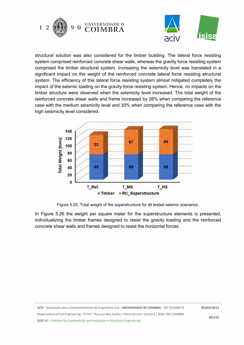
ACIV - Associação para o Desenvolvimento da Engenharia Civil - UNIVERSIDADE DE COIMBRA – NIF 505448173
Departament of Civil Engineering - FCTUC * Rua Luís Reis Santos | Pólo II da Univ. Coimbra | 3030-788 COIMBRA
ISISE UC – Institute for Sustainability and Innovation in Structural Engineering
RE2019.0513
84|210
structural solution was also considered for the timber building. The lateral force resisting system comprised reinforced concrete shear walls, whereas the gravity force resisting system comprised the timber structural system. Increasing the seismicity level was translated in a significant impact on the weight of the reinforced concrete lateral force resisting structural system. The efficiency of this lateral force resisting system almost mitigated completely the impact of the seismic loading on the gravity force resisting system. Hence, no impacts on the timber structure were observed when the seismicity level increased. The total weight of the reinforced concrete shear walls and frame increased by 26% when comparing the reference case with the medium seismicity level and 30% when comparing the reference case with the high seismicity level considered.
Figure 5.25. Total weight of the superstructure for all tested seismic scenarios.
In Figure 5.26 the weight per square meter for the superstructure elements is presented, individualizing the timber frames designed to resist the gravity loading and the reinforced concrete shear walls and frames designed to resist the horizontal forces.

ACIV - Associação para o Desenvolvimento da Engenharia Civil - UNIVERSIDADE DE COIMBRA – NIF 505448173
Departament of Civil Engineering - FCTUC * Rua Luís Reis Santos | Pólo II da Univ. Coimbra | 3030-788 COIMBRA
ISISE UC – Institute for Sustainability and Innovation in Structural Engineering
RE2019.0513
85|210
Figure 5.26. Weight per square meter of the superstructure for all tested seismic scenarios.
As previously mentioned, the impact of the seismic action on the gravity resisting frame was eliminated. The weight of the lateral force resisting system increased proportionally, according to the seismicity level considered.
5.2.6 Reinforced Concrete Shear Wall System
In Figure 5.27 a comparison is established between the overall weight estimation for the Reinforced Concrete Shear Wall building for the different seismicity levels considered. The defined structural categories are compared.
Figure 5.27. Total weight comparison between all tested seismic scenarios.

ACIV - Associação para o Desenvolvimento da Engenharia Civil - UNIVERSIDADE DE COIMBRA – NIF 505448173
Departament of Civil Engineering - FCTUC * Rua Luís Reis Santos | Pólo II da Univ. Coimbra | 3030-788 COIMBRA
ISISE UC – Institute for Sustainability and Innovation in Structural Engineering
RE2019.0513
86|210
Specifically, for this building type the lateral load and gravity load resisting systems are the reinforced concrete shear walls. Consequently, the shear walls are the heaviest element of the building.
5.2.7 Comparison between all different structural solutions
Finally, in this section comparison between the structural alternatives is carried out on the basis of increasing level of the seismic action. The comparison, analysis and discussion are conducted on the basis of the results obtained from the structural analysis.
Seismic loads are directly related to some factors. The two main factors that impact its intensity are the mobilized mass (that depends directly on the structural weight as other masses remain constant in all cases) and the structural behaviour factor. Regarding the first aspect, cold-formed steel has advantages as its weight is usually much lower than other structural solutions.
After analysis of all structural systems considering the established seismic scenarios, some variations were observed in terms of the seismic loads.
In Table 5.24 the total weight estimated for all studied scenarios, as a function of the used materials and structural function is presented. Graphically, in Figure 5.28 all the information, for the initially investigated scenarios, is depicted. The impact of the seismic location was more relevant for the total weight of the reinforced concrete buildings.
Figure 5.28. Total weight comparison between initially tested structural solutions.

ACIV - Associação para o Desenvolvimento da Engenharia Civil - UNIVERSIDADE DE COIMBRA – NIF 505448173
Departament of Civil Engineering - FCTUC * Rua Luís Reis Santos | Pólo II da Univ. Coimbra | 3030-788 COIMBRA
ISISE UC – Institute for Sustainability and Innovation in Structural Engineering
RE2019.0513
87|210
Table 5.24. Comparison of the total structural materials weight.
Structural solution
Superstructure
Found. [tons]
Slabs Gravitational loads resisting elements
Lateral resisting elements
Light-Steel
framing [tons]
Hot-rolled steel [tons]
Concrete Frames [tons]
Timber [tons]
MRF or shear walls [tons]
Slabs [tons]
Steel Deck [tons]
CFS_Ref._G550I 46 0.5 5.9 305.2 232.2 12.92 CFS_Ref._G550II 44 1.6 96.6 305.2 232.2 12.92 CFS_MS_G550 55 0.5 11.8 305.2 232.2 12.92 CFS_HS_G550I 55 0.5 15.1 305.2 232.2 12.92 CFS_HS_G550II 55 1.6 126.6 305.2 232.2 12.92 CFS_Ref._S320I 52 0.5 5.9 305.2 232.2 12.92 CFS_Ref._S320II 51 1.6 96.6 305.2 232.2 12.92 CFS_MS_S320 62 0.5 11.8 305.2 232.2 12.92 CFS_HS_S320I 62 0.5 15.1 305.2 232.2 12.92 CFS_HS_S320II 62 1.6 126.1 305.2 232.2 12.92 HRS_S355_RefI 45.4 9.3 375.0 336.0 12.92 HRS_S355_RefII 51.8 75.3 364.0 336.0 12.92 HRS_S355_MS 46.7 12.9 435.4 336.0 12.92 HRS_S355_HSI 48.9 15.2 435.4 336.0 12.92 HRS_S355_HSII 53.7 76.7 421.3 336.0 12.92 HRS_S460_RefI 39.8 8.3 375.0 336.0 12.92 HRS_S460_RefII 45.3 75.3 364.0 336.0 12.92 HRS_S460_MS 42.4 9.3 435.4 336.0 12.92 HRS_S460_HSI 42.3 9.9 435.4 336.0 12.92 HRS_S460_HSII 49.9 76.7 421.3 336.0 12.92
RC_Ref. 205.8 95.0 425.2 602.7 RC_MS 191.5 125.1 529.5 602.7 RC_HS 264.0 126.3 529.5 669.5 T_Ref. 69.3 53.1 357.5 275.7 T_MS 69.3 67.4 357.5 275.7 T_HS 69.3 68.7 357.5 275.7
RC_SW_Ref 894.6 282.0 460.8 RC_SW_MS 898.5 338.3 460.8 RC_SW_HS 898.5 338.3 460.8
CFS_Ref – Light steel framing building subject to wind loading; CFS_MS / HS – Light steel framing building subject to low seismic action / high seismic action;

ACIV - Associação para o Desenvolvimento da Engenharia Civil - UNIVERSIDADE DE COIMBRA – NIF 505448173
Departament of Civil Engineering - FCTUC * Rua Luís Reis Santos | Pólo II da Univ. Coimbra | 3030-788 COIMBRA
ISISE UC – Institute for Sustainability and Innovation in Structural Engineering
RE2019.0513
88|210
Structural solution
Superstructure
Found. [tons]
Slabs Gravitational loads resisting elements
Lateral resisting elements
Light-Steel
framing [tons]
Hot-rolled steel [tons]
Concrete Frames [tons]
Timber [tons]
MRF or shear walls [tons]
Slabs [tons]
Steel Deck [tons]
HRS_LS / MS / HS – Hot-rolled steel building subject to low seismic action / high seismic action; RC_LS / MS / HS – Reinforced concrete building subject to low seismic action / high seismic action; T_LS / HS – Timber building subject to low seismic action / high seismic action. RC_SW_MS / HS – Reinforced concrete shear walls building subject to medium seismic action / high seismic action.
Figure 5.29. Total weight comparison between all tested structural solutions.
Since the weight of the foundations and slabs represent a significant part of the overall weight a new comparison is established. In Figure 5.30 only for the vertical superstructure elements, disregarding the weight of the foundations and slabs.
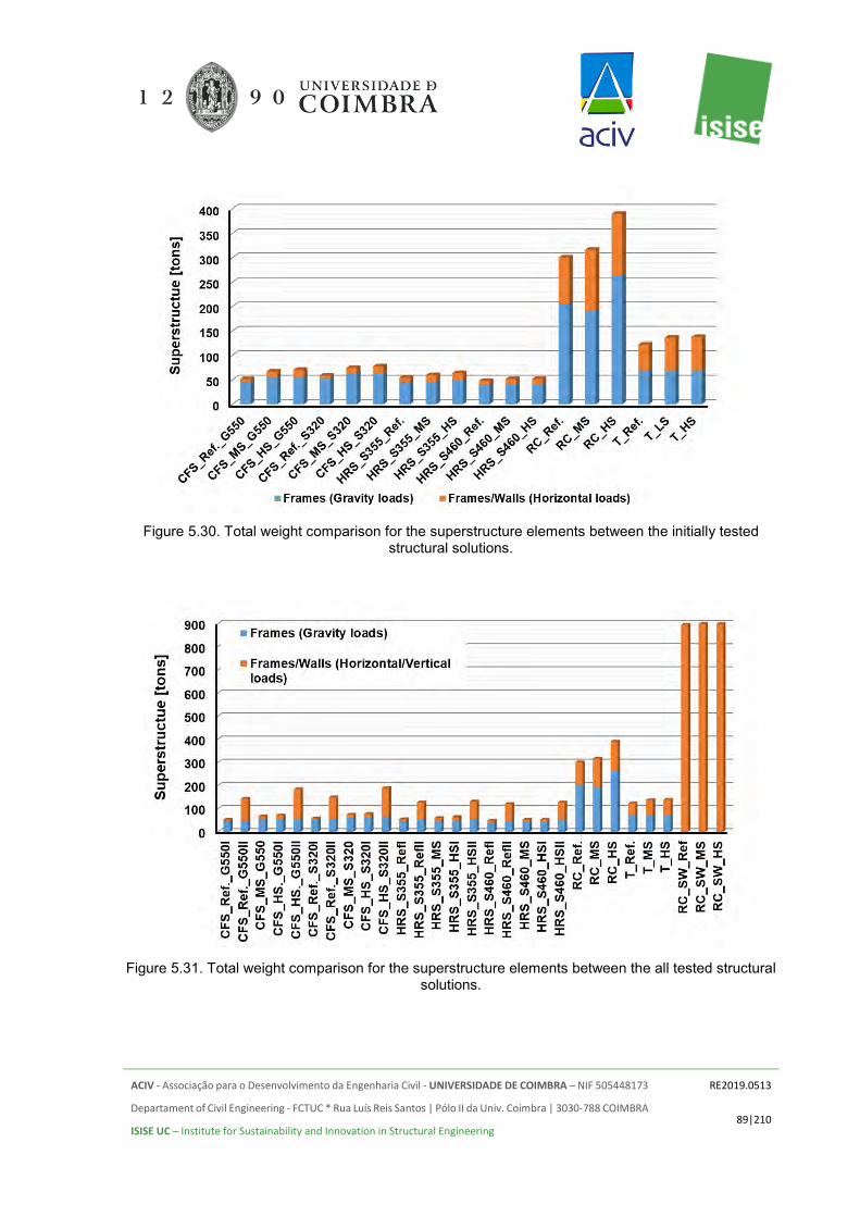
ACIV - Associação para o Desenvolvimento da Engenharia Civil - UNIVERSIDADE DE COIMBRA – NIF 505448173
Departament of Civil Engineering - FCTUC * Rua Luís Reis Santos | Pólo II da Univ. Coimbra | 3030-788 COIMBRA
ISISE UC – Institute for Sustainability and Innovation in Structural Engineering
RE2019.0513
89|210
Figure 5.30. Total weight comparison for the superstructure elements between the initially tested
structural solutions.
Figure 5.31. Total weight comparison for the superstructure elements between the all tested structural
solutions.
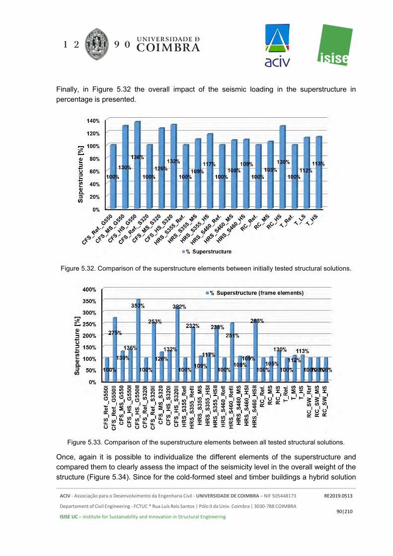
ACIV - Associação para o Desenvolvimento da Engenharia Civil - UNIVERSIDADE DE COIMBRA – NIF 505448173
Departament of Civil Engineering - FCTUC * Rua Luís Reis Santos | Pólo II da Univ. Coimbra | 3030-788 COIMBRA
ISISE UC – Institute for Sustainability and Innovation in Structural Engineering
RE2019.0513
90|210
Finally, in Figure 5.32 the overall impact of the seismic loading in the superstructure in percentage is presented.
Figure 5.32. Comparison of the superstructure elements between initially tested structural solutions.
Figure 5.33. Comparison of the superstructure elements between all tested structural solutions.
Once, again it is possible to individualize the different elements of the superstructure and compared them to clearly assess the impact of the seismicity level in the overall weight of the structure (Figure 5.34). Since for the cold-formed steel and timber buildings a hybrid solution

ACIV - Associação para o Desenvolvimento da Engenharia Civil - UNIVERSIDADE DE COIMBRA – NIF 505448173
Departament of Civil Engineering - FCTUC * Rua Luís Reis Santos | Pólo II da Univ. Coimbra | 3030-788 COIMBRA
ISISE UC – Institute for Sustainability and Innovation in Structural Engineering
RE2019.0513
91|210
was adopted it is important to clearly understand if the lateral force resisting systems work adequately.
Figure 5.34. Comparison of the individualized superstructure elements between all tested structural
solutions.
Observing the obtained results, the impact of the seismicity level is clear on the lateral force resisting systems. For instance, for the cold-formed steel building, the impact on the lateral force resisting system is high, but it is worth noting that the actual weight of the hot-rolled lateral force resisting system is relatively low.
Furthermore, the estimated total weight per square meter (total area of 1384 m2) for each structural solution is summarized in Table 5.25 and graphically in Figure 5.35.
Figure 5.35. Total weight per sqm comparison between initially tested structural solutions.
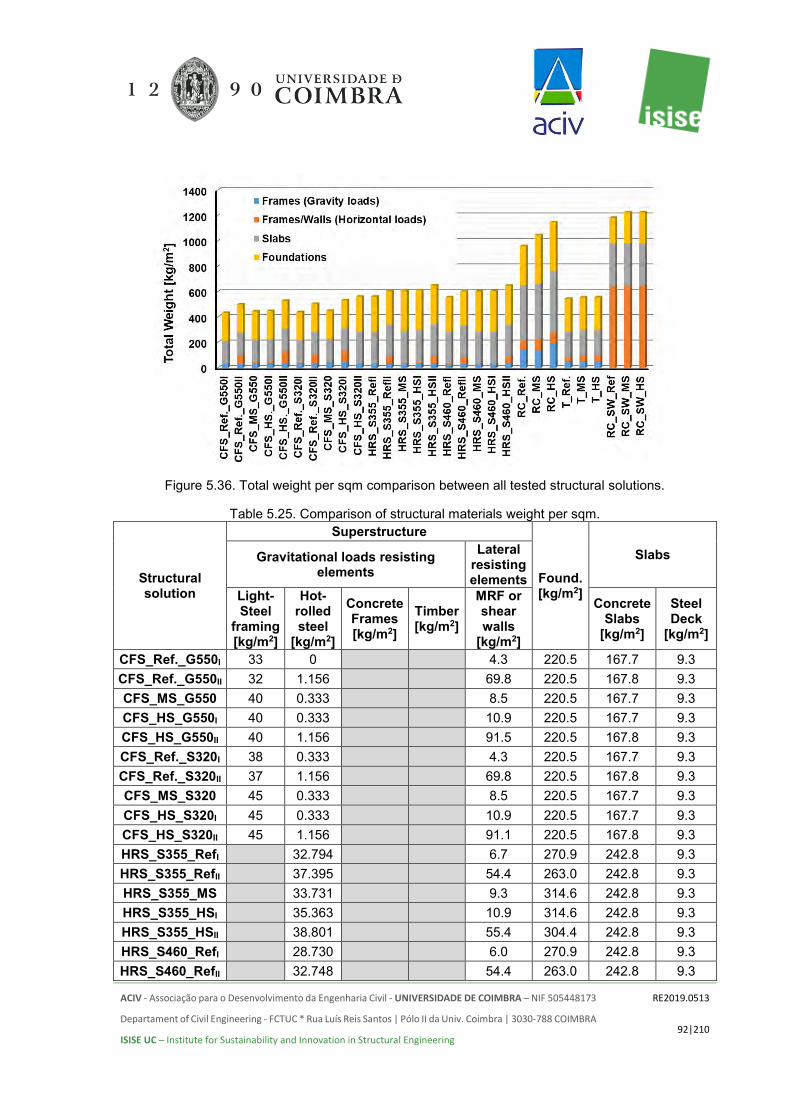
ACIV - Associação para o Desenvolvimento da Engenharia Civil - UNIVERSIDADE DE COIMBRA – NIF 505448173
Departament of Civil Engineering - FCTUC * Rua Luís Reis Santos | Pólo II da Univ. Coimbra | 3030-788 COIMBRA
ISISE UC – Institute for Sustainability and Innovation in Structural Engineering
RE2019.0513
92|210
Figure 5.36. Total weight per sqm comparison between all tested structural solutions.
Table 5.25. Comparison of structural materials weight per sqm.
Structural solution
Superstructure
Found. [kg/m2]
Slabs Gravitational loads resisting elements
Lateral resisting elements
Light-Steel
framing [kg/m2]
Hot-rolled steel
[kg/m2]
Concrete Frames [kg/m2]
Timber [kg/m2]
MRF or shear walls
[kg/m2]
Concrete Slabs
[kg/m2]
Steel Deck
[kg/m2]
CFS_Ref._G550I 33 0 4.3 220.5 167.7 9.3 CFS_Ref._G550II 32 1.156 69.8 220.5 167.8 9.3 CFS_MS_G550 40 0.333 8.5 220.5 167.7 9.3 CFS_HS_G550I 40 0.333 10.9 220.5 167.7 9.3 CFS_HS_G550II 40 1.156 91.5 220.5 167.8 9.3 CFS_Ref._S320I 38 0.333 4.3 220.5 167.7 9.3 CFS_Ref._S320II 37 1.156 69.8 220.5 167.8 9.3 CFS_MS_S320 45 0.333 8.5 220.5 167.7 9.3 CFS_HS_S320I 45 0.333 10.9 220.5 167.7 9.3 CFS_HS_S320II 45 1.156 91.1 220.5 167.8 9.3 HRS_S355_RefI 32.794 6.7 270.9 242.8 9.3 HRS_S355_RefII 37.395 54.4 263.0 242.8 9.3 HRS_S355_MS 33.731 9.3 314.6 242.8 9.3 HRS_S355_HSI 35.363 10.9 314.6 242.8 9.3 HRS_S355_HSII 38.801 55.4 304.4 242.8 9.3 HRS_S460_RefI 28.730 6.0 270.9 242.8 9.3 HRS_S460_RefII 32.748 54.4 263.0 242.8 9.3

ACIV - Associação para o Desenvolvimento da Engenharia Civil - UNIVERSIDADE DE COIMBRA – NIF 505448173
Departament of Civil Engineering - FCTUC * Rua Luís Reis Santos | Pólo II da Univ. Coimbra | 3030-788 COIMBRA
ISISE UC – Institute for Sustainability and Innovation in Structural Engineering
RE2019.0513
93|210
HRS_S460_MS 30.646 6.7 314.6 242.8 9.3 HRS_S460_HSI 30.591 7.1 314.6 242.8 9.3 HRS_S460_HSII 36.082 55.4 304.4 242.8 9.3
RC_Ref. 148.7 68.6 307.2 435.5
RC_MS 138.4 90.4 382.6 435.5
RC_HS 190.8 91.2 382.6 483.8
T_Ref. 50.1 38.4 258.3 199.2
T_MS 50.1 48.7 258.3 199.2
T_HS 50.1 49.6 258.3 199.2
RC_SW_Ref 646.4 203.8 333.0
RC_SW_MS 649.2 244.4 333.0
RC_SW_HS 649.2 244.4 333.0
CFS_Wind – Light steel framing building subject to wind loading; CFS_MS / HS – Light steel frmaing building subject to low seismic action / high seismic action; HRS_LS / MS / HS – Hot-rolled steel building subject to low seismic action / high seismic action; RC_LS / MS / HS – Reinforced concrete building subject to low seismic action / high seismic action; T_LS / HS – Timber building subject to low seismic action / high seismic action.
Further comparison is shown in Figure 5.37, where the weight of the slabs is disregarded in order to show the direct impact of the weight increase of the vertical structural members. Here, only the superstructure elements are used for comparison purposes.
Figure 5.37. Frames and walls´ weight increase in % between the initially tested structural solutions.

ACIV - Associação para o Desenvolvimento da Engenharia Civil - UNIVERSIDADE DE COIMBRA – NIF 505448173
Departament of Civil Engineering - FCTUC * Rua Luís Reis Santos | Pólo II da Univ. Coimbra | 3030-788 COIMBRA
ISISE UC – Institute for Sustainability and Innovation in Structural Engineering
RE2019.0513
94|210
Figure 5.38. Frames and walls´ weight increase in % between all tested structural solutions.
From the analysis of the results the following conclusions may be drawn as follows:
• Cold-formed and hot-rolled steel solutions present much lower structural weight per square meter comparing to reinforced concrete buildings. This has a direct impact on the design of the foundations;
• For cold-formed steel buildings, the vertical resisting structure (gravity loads) can be considered as internal partitions and external facades, representing cost savings with materials and labour and faster construction time.
• For the hot-rolled steel solutions, the central core is responsible for resisting a great portion of horizontal loads, what was expected. The hot-rolled steel profiles weight from core had increased by more than 100% related to reference building, without seismic loads. On the other hand, the weight of other columns and beams remained the same, as they were designed to resist basically vertical loads.
• For the reinforced concrete solution, the percentage weight increase for locations with seismic hazards was higher than other solutions. This is due to the fact that this solution has a much higher mass, besides greater rigidity, which increases the seismic load applied to the base. In addition, concrete solutions have generally lower behavior factor than steel solutions, i.e., less capacity to absorb energy. Thus, this type of solution presents disadvantages in locations with high seismicity levels.
• It can be observed that the horizontal base reactions vary depending on several factors, such as the total seismic mass and the rigidity of the building. Considering this aspect,

ACIV - Associação para o Desenvolvimento da Engenharia Civil - UNIVERSIDADE DE COIMBRA – NIF 505448173
Departament of Civil Engineering - FCTUC * Rua Luís Reis Santos | Pólo II da Univ. Coimbra | 3030-788 COIMBRA
ISISE UC – Institute for Sustainability and Innovation in Structural Engineering
RE2019.0513
95|210
light steel framing has some advantages over the other solutions, since they have much lower mass.
• Hot-rolled steel building does not require formwork or a significant amount of shoring but has extra costs with secondary structures for facades and internal walls.
• The reinforced concrete building has additional costs with formwork, shoring, reinforcement processing (cutting and folding), a secondary structure for facades and internal walls
• The comparison in terms of material costs is not relevant. This should be analysed using a life-cycle cost assessment.
5.3 IMPACT ON FOUNDATIONS
The different structural schemes tested, and the seismicity levels considered influenced significantly the overall design of the foundations. The impact of the structural system on the foundations was assessed and compared between all tested structural solutions and seismicity levels.
Foundations shall be checked against failure by sliding and against bearing capacity failure. Failure by sliding shall be resisted trough friction and lateral earth pressure. For the bearing capacity failure, load inclination and eccentricity arising from the inertia forces in the structure as well as the possible effects of the inertia forces in supporting soil itself shall be taken into account.
Figure 5.39. Total base reaction in the X direction.
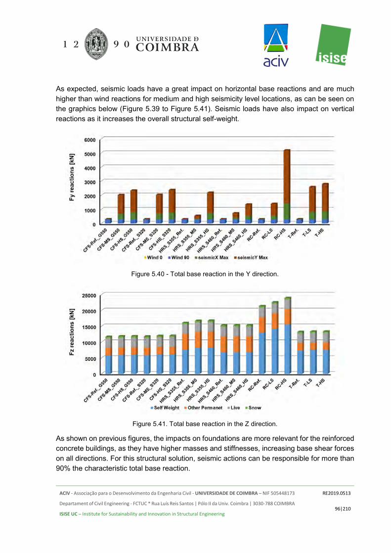
ACIV - Associação para o Desenvolvimento da Engenharia Civil - UNIVERSIDADE DE COIMBRA – NIF 505448173
Departament of Civil Engineering - FCTUC * Rua Luís Reis Santos | Pólo II da Univ. Coimbra | 3030-788 COIMBRA
ISISE UC – Institute for Sustainability and Innovation in Structural Engineering
RE2019.0513
96|210
As expected, seismic loads have a great impact on horizontal base reactions and are much higher than wind reactions for medium and high seismicity level locations, as can be seen on the graphics below (Figure 5.39 to Figure 5.41). Seismic loads have also impact on vertical reactions as it increases the overall structural self-weight.
Figure 5.40 - Total base reaction in the Y direction.
Figure 5.41. Total base reaction in the Z direction.
As shown on previous figures, the impacts on foundations are more relevant for the reinforced concrete buildings, as they have higher masses and stiffnesses, increasing base shear forces on all directions. For this structural solution, seismic actions can be responsible for more than 90% the characteristic total base reaction.

ACIV - Associação para o Desenvolvimento da Engenharia Civil - UNIVERSIDADE DE COIMBRA – NIF 505448173
Departament of Civil Engineering - FCTUC * Rua Luís Reis Santos | Pólo II da Univ. Coimbra | 3030-788 COIMBRA
ISISE UC – Institute for Sustainability and Innovation in Structural Engineering
RE2019.0513
97|210
Lightweight solutions, such as cold-formed steel and hot-rolled steel buildings, have advantages related to this aspect, as they mobilize lower seismic masses and have better response under these scenarios. These advantages become more significant as the seismicity level of the construction site increase.
Another important factor that must be taken into account is that steel structures, generally, can have a higher behaviour factor in seismic scenarios, as their energy dissipative capacity is often greater than concrete structures. This fact leads to lower design seismic actions applied to these solutions.
Regarding the adopted foundation systems for each one of the structural solutions, the estimated weights for the foundations are presented in Table 5.26 and depicted in Figure 5.42 as a function of the seismicity levels investigated. As expected, the foundations for the cold-formed steel and timber buildings are the lightest, and the foundations for the reinforced concrete solution the heaviest. It is worth noting, and as previously mentioned, that in this comparison different foundation systems were adopted. For both cold-formed steel and timber buildings, a raft foundation was adopted whereas for the hot-rolled steel and reinforced concrete buildings a pad foundation system with equilibrium beams and suspended ground floor slab was adopted.
Table 5.26. Weight estimation for the foundations according to the investigated scenarios. Structural solution Foundation [ton] Structural solution Foundation [ton]
CFS_Ref._G550I 305.2 HRS_S460_RefI 375.0 CFS_Ref._G550II 305.2 HRS_S460_RefII 364.0 CFS_MS_G550 305.2 HRS_S460_MS 435.4 CFS_HS_G550I 305.2 HRS_S460_HSI 435.4 CFS_HS_G550II 305.2 HRS_S460_HSII 421.3 CFS_Ref._S320I 305.2 RC_Ref. 425.2 CFS_Ref._S320II 305.2 RC_MS 529.5 CFS_MS_S320 305.2 RC_HS 529.5 CFS_HS_S320 305.2 T_Ref. 357.5 HRS_S355_RefI 375.0 T_MS 357.5 HRS_S355_RefII 364.0 T_HS 357.5 HRS_S355_MS 435.4 RC_SW_Ref 282.0 HRS_S355_HSI 435.4 RC_SW_MS 338.3 HRS_S355_HSII 421.3 RC_SW_HS 338.3

ACIV - Associação para o Desenvolvimento da Engenharia Civil - UNIVERSIDADE DE COIMBRA – NIF 505448173
Departament of Civil Engineering - FCTUC * Rua Luís Reis Santos | Pólo II da Univ. Coimbra | 3030-788 COIMBRA
ISISE UC – Institute for Sustainability and Innovation in Structural Engineering
RE2019.0513
98|210
Figure 5.42. Weight comparison for the different foundation systems adopted for initially defined type
of buildings as a function of the seismicity level.
Figure 5.43. Weight comparison for the different foundation systems adopted for all buildings as a
function of the seismicity level.
In Figure 5.44 a comparison in terms of percentage is established using as base value the weight of the foundation for the reference building for each structural material.

ACIV - Associação para o Desenvolvimento da Engenharia Civil - UNIVERSIDADE DE COIMBRA – NIF 505448173
Departament of Civil Engineering - FCTUC * Rua Luís Reis Santos | Pólo II da Univ. Coimbra | 3030-788 COIMBRA
ISISE UC – Institute for Sustainability and Innovation in Structural Engineering
RE2019.0513
99|210
Figure 5.44. Comparison between the different foundation systems adopted for each type of building
as a function of the seismicity level.
Figure 5.45. Comparison between the different foundation systems adopted for all types of buildings
investigated as a function of the seismicity level.
In Figure 5.46 a more global comparison is established. For this specific comparison, the lightest foundation was used as a reference to assess the weight increase for the others. The

ACIV - Associação para o Desenvolvimento da Engenharia Civil - UNIVERSIDADE DE COIMBRA – NIF 505448173
Departament of Civil Engineering - FCTUC * Rua Luís Reis Santos | Pólo II da Univ. Coimbra | 3030-788 COIMBRA
ISISE UC – Institute for Sustainability and Innovation in Structural Engineering
RE2019.0513
100|210
lightest solution is the one used for the cold-formed steel buildings (100%). Observing the obtained results, it can be stated that the foundation's weight is about 39% higher for the reference reinforced concrete building when compared with the reference cold-formed steel building, and 23% higher for the hot-rolled steel building when compared with the cold-formed steel building.
Figure 5.46. Variation of the weight of the foundations for the initially studied scenarios.
Figure 5.47. Variation of the weight of the foundations for all studied scenarios.

ACIV - Associação para o Desenvolvimento da Engenharia Civil - UNIVERSIDADE DE COIMBRA – NIF 505448173
Departament of Civil Engineering - FCTUC * Rua Luís Reis Santos | Pólo II da Univ. Coimbra | 3030-788 COIMBRA
ISISE UC – Institute for Sustainability and Innovation in Structural Engineering
RE2019.0513
101|210
As some global comments, it was observed that the weight of the foundations for the reinforced concrete solution was 39% higher than the cold-formed steel building and 13% higher than the hot-rolled steel foundations for the reference case (without seismic action). For the high seismic location, the overall impact is even greater, since for the reinforced concrete the weight of the foundation was 74% higher than the cold-formed steel building and 22% higher than the hot-rolled steel building. The weight of the timber foundation is 17% higher than the weight of the cold-formed steel foundation.
5.4 CONCRETE CONSUMPTION
Concrete is still one of the most used materials in construction, however, it is recognized that despite all the undertaken efforts in the last few years is still considered an environmentally unfriendly material. In this Section, a comparison is established between all tested solutions in terms of concrete consumption. As previously mentioned, the adopted concrete class was the C30/37, and an appropriate concrete composition was prescribed, detailing all the materials involved in the mix as well as the corresponding quantities.
In this study, it was assumed that all studied solutions would incorporate concrete foundations and slabs (flat reinforced concrete slabs and composite slabs comprising steel deck or timber deck and reinforced concrete). In Figure 5.48 the concrete weight and the weight of the materials in the concrete mix are presented for each one of the studied structural solutions for the reference situation (no-seismic action).
Figure 5.48. Concrete weight per building type and weight of the materials in the concrete mix for the
reference cases.

ACIV - Associação para o Desenvolvimento da Engenharia Civil - UNIVERSIDADE DE COIMBRA – NIF 505448173
Departament of Civil Engineering - FCTUC * Rua Luís Reis Santos | Pólo II da Univ. Coimbra | 3030-788 COIMBRA
ISISE UC – Institute for Sustainability and Innovation in Structural Engineering
RE2019.0513
102|210
For the reference, case studied and for each one of the framing solutions, the reduction in concrete consumption was assessed. Comparing reinforced concrete and hot-rolled steel cases the reduction in concrete consumption is 46.1%. Comparing the reinforced concrete solution with the cold-formed steel one, the concrete consumption decreased 59.7%, and comparing the reinforced concrete solution with the timber one, the reduction in concrete consumption is 53.3%.
In Figure 5.49 the concrete weight and the weight of the materials in the concrete mix are presented for each one of the studied structural solutions for the high seismic situation.
Figure 5.49. Concrete weight per building type and weight of the materials in the concrete mix for the
high seismic cases.
For the high seismicity level and for each one of the framing solutions, the reduction in concrete consumption was assessed. Comparing reinforced concrete and hot-rolled steel cases the reduction in concrete consumption is 51.1%. Comparing the reinforced concrete solution with the cold-formed steel one, the concrete consumption decreased 66.2%, and comparing the reinforced concrete solution with the timber one, the reduction in concrete consumption is 60.9%. The consumption reduction of the materials selected for the concrete mix is the same. For instance, the reduction of water consumption, when comparing the reinforced concrete framing solution with the cold-formed steel framing solution is 66.2%
The higher concrete quantity used in the reinforced concrete solutions will be translated as well in higher waste (excess material). The presented values and comparisons don’t include waste allowance. Usually, waste (excess material) for foundations is assumed as 5% and for superstructure as 2%. The excess material shall be properly handled, and proper planning is required to tackle this problem, hence while planning the construction programme the possibility of reuse the excess of concrete or recycle the excess material should be considered.

ACIV - Associação para o Desenvolvimento da Engenharia Civil - UNIVERSIDADE DE COIMBRA – NIF 505448173
Departament of Civil Engineering - FCTUC * Rua Luís Reis Santos | Pólo II da Univ. Coimbra | 3030-788 COIMBRA
ISISE UC – Institute for Sustainability and Innovation in Structural Engineering
RE2019.0513
103|210
5.5 ACOUSTIC PERFORMANCE
5.5.1 Cold-Formed Steel
In Table 5.27 the results obtained for the sound insulation from the outside (facade insulation) are shown, taking into account the two types of lightweight facades shown above (with and without insulation from the outside - ETICS). As can be seen from the presented results, and as it would be expected, the airborne sound insulation depends mainly on the lower performance of the facade elements, which usually correspond to the windows (glass, frame and any additional elements, namely shutter boxes and vents). These results are shown using two types of windows with different performances.
Table 5.27. Airborne sound insulation results between the exterior and rooms or kitchens (for the most unfavourable situations).
Facade solution Window type Compartment Global insulation parameters
Qualitative evaluation
Without ETICS
With window Rw + Ctr = 29
dB
Bedroom D2m, nT, w (C; Ctr) = 42 (-2; -6) dB Sufficient
Living room D2m, nT, w (C Ctr) 44 = (-2, -5) dB Good
Kitchen D2m, nT, w (C; Ctr) = 42 (-2; -6) dB Good
With window Rw + Ctr = 34
dB
Bedroom D2m, nT, w (C Ctr) 45 = (-2, -5) dB Good
Living room D2m, nT, w (C; Ctr) = 47 (-1; -5) dB Excellent
Kitchen D2m, nT, w (C Ctr) 45 = (-2, -5) dB Excellent
With window Rw + Ctr = 38
dB
Bedroom D2m, nT, w (C; Ctr) = 48 (-2; -6) dB Excellent
Living room D2m, nT, w (C; Ctr) = 50 (-1; -5) dB Excellent
Kitchen D2m, nT, w (C Ctr) 48 = (-2, -5) dB Excellent
With window Rw + Ctr = 29
dB
Bedroom D2m, nT, w (C; Ctr) = 43 (-3, -6) dB Sufficient
Living room D2m, nT, w (C; Ctr) = 45 (-3, -6) dB Good
Kitchen D2m, nT, w (C; Ctr) = 43 (-3, -6) dB Good

ACIV - Associação para o Desenvolvimento da Engenharia Civil - UNIVERSIDADE DE COIMBRA – NIF 505448173
Departament of Civil Engineering - FCTUC * Rua Luís Reis Santos | Pólo II da Univ. Coimbra | 3030-788 COIMBRA
ISISE UC – Institute for Sustainability and Innovation in Structural Engineering
RE2019.0513
104|210
Facade solution Window type Compartment Global insulation parameters
Qualitative evaluation
With ETICS
With window Rw + Ctr = 34
dB
Bedroom D2m, nT, w (C Ctr) 45 = (-2, -5) dB Good
Living room D2m, nT, w (C Ctr) 48 = (-2, -5) dB Excellent
Kitchen D2m, nT, w (C Ctr) =45 (-2, -5) dB Excellent
With window Rw + Ctr =
38 dB
Bedroom D2m, nT, w (C Ctr) = 49 (-2, -5) dB Excellent
Living room D2m, nT, w (C; Ctr) = 51 (-1; -4) dB Excellent
Kitchen D2m, nT, w (C Ctr) =49 (-2, -5) dB Excellent
In the following paragraphs, the results obtained for the airborne acoustic insulation between interior compartments of the building are presented. In the case of partitions, simulations were performed for standard plasterboard panels (STD). If different plasterboard panels are used, acoustic performance differences may be reduced, particularly for higher densities. For example, for plasterboard with a density increase of the order of 15 to 20% from the STD solution, for a straight partition element, the increase in airborne sound insulation indices can be of about 1 dB.
Since the airborne sound insulation between compartments depends not only on the direct separation elements, but also on the marginal elements, and in order to meet the necessary acoustic requirements, improvements were needed for the basic solutions evaluated in other areas of expertise in this report, at the level of the partitions, and especially at the level of the floors and ceilings. In Figure 5.50 the improvement solutions are presented in what concerns the floors. In Figure 5.51, the suspended ceiling solutions are represented, including the basic solution and two improvement solutions. Finally, in Figure 5.52, the solutions of direct partition wall between apartments or between circulation zones and apartments are presented.
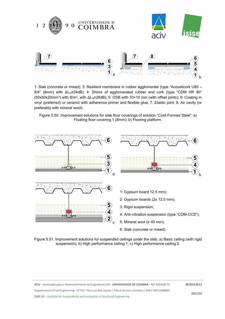
ACIV - Associação para o Desenvolvimento da Engenharia Civil - UNIVERSIDADE DE COIMBRA – NIF 505448173
Departament of Civil Engineering - FCTUC * Rua Luís Reis Santos | Pólo II da Univ. Coimbra | 3030-788 COIMBRA
ISISE UC – Institute for Sustainability and Innovation in Structural Engineering
RE2019.0513
105|210
a b
1: Slab (concrete or mixed); 3: Resilient membrane in rubber agglomerate (type “Acousticork U85 – 8/4” (8mm) with ΔLw≥24dB); 4: Shims of agglomerated rubber and cork (type “CDM HR 80” (50x50x20mm3) with 8/m2, with ΔLw≥28dB); 5: OSB with 10+10 mm (with offset joints); 6: Coating in vinyl (preferred) or ceramic with adherence primer and flexible glue; 7: Elastic joint; 8: Air cavity (or preferably with mineral wool).
Figure 5.50. Improvement solutions for slab floor coverings of solution “Cold-Formed Steel”: a) Floating floor covering 1 (8mm); b) Flooring platform.
a b
c
1: Gypsum board 12.5 mm);
2: Gypsum boards (2x 12.5 mm);
3: Rigid suspension;
4: Anti-vibration suspension (type “CDM-CCS”);
5: Mineral wool (≥ 40 mm);
6: Slab (concrete or mixed).
Figure 5.51. Improvement solutions for suspended ceilings under the slab: a) Basic ceiling (with rigid suspension); b) High performance ceiling 1; c) High performance ceiling 2.
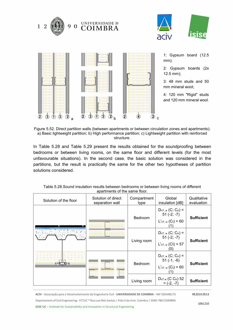
ACIV - Associação para o Desenvolvimento da Engenharia Civil - UNIVERSIDADE DE COIMBRA – NIF 505448173
Departament of Civil Engineering - FCTUC * Rua Luís Reis Santos | Pólo II da Univ. Coimbra | 3030-788 COIMBRA
ISISE UC – Institute for Sustainability and Innovation in Structural Engineering
RE2019.0513
106|210
a b c
1: Gypsum board (12.5 mm);
2: Gypsum boards (2x 12.5 mm);
3: 48 mm studs and 50 mm mineral wool;
4: 120 mm "Rigid" studs and 120 mm mineral wool.
Figure 5.52. Direct partition walls (between apartments or between circulation zones and apartments): a) Basic lightweight partition; b) High performance partition; c) Lightweight partition with reinforced
structure.
In Table 5.28 and Table 5.29 present the results obtained for the soundproofing between bedrooms or between living rooms, on the same floor and different levels (for the most unfavourable situations). In the second case, the basic solution was considered in the partitions, but the result is practically the same for the other two hypotheses of partition solutions considered.
Table 5.28.Sound insulation results between bedrooms or between living rooms of different apartments of the same floor.
Solution of the floor Solution of direct separation wall
Compartment type
Global insulation [dB]
Qualitative evaluation
Bedroom
DnT, w (C; Ctr) = 51 (-2; -7)
L'nT, w (CI) = 60 (1)
Sufficient
Living room
DnT, w (C; Ctr) = 51 (-2; -7)
L'nT, w (CI) = 57 (0)
Sufficient
Bedroom
DnT, w (C; Ctr) = 51 (-1, -6)
L'nT, w (CI) = 60 (1)
Sufficient
Living room DnT w (C Ctr) 52 = (-2, -7) Sufficient

ACIV - Associação para o Desenvolvimento da Engenharia Civil - UNIVERSIDADE DE COIMBRA – NIF 505448173
Departament of Civil Engineering - FCTUC * Rua Luís Reis Santos | Pólo II da Univ. Coimbra | 3030-788 COIMBRA
ISISE UC – Institute for Sustainability and Innovation in Structural Engineering
RE2019.0513
107|210
Solution of the floor Solution of direct separation wall
Compartment type
Global insulation [dB]
Qualitative evaluation
L'nT, w (CI) = 57 (0)
Bedroom
DnT, w (C; Ctr) = 50 (-2; -6) *
L'nT, w (CI) = 60 (1)
Sufficient
Living room
DnT, w (C; Ctr) = 50 (-1, -5) *
L'nT, w (CI) = 57 (0)
Sufficient
Bedroom
DnT, w (C; Ctr) = 56 (-4, -11)
L'nT, w (CI) = 51 (6)
Good
Living room
DnT, w (C; Ctr) = 57 (-5, -12)
L'nT, w (CI) = 48 (6)
Good
bedroom
DnT, w (C; Ctr) = 60 (-5, -13) **
L'nT, w (CI) = 51 (6)
Excellent
Living room
DnT, w (C; Ctr) = 60 (-6, -13)
L'nT, w (CI) = 48 (6)
Excellent
( *) Estimated values if a " Tecsound BAND 50 - Texsa " type elastomeric band (2.5 mm) is applied to the tops of the stud, between the stud and the plasterboard. If this band is not applied a reduction in the value of DnT,w of 1 dB is expected. (* *) Predicted values with suspended ceiling solution with resilient supports ( Best Ceiling 1). With the rigid suspension system a reduction of 1 dB in the value of DnT,w shall occur.

ACIV - Associação para o Desenvolvimento da Engenharia Civil - UNIVERSIDADE DE COIMBRA – NIF 505448173
Departament of Civil Engineering - FCTUC * Rua Luís Reis Santos | Pólo II da Univ. Coimbra | 3030-788 COIMBRA
ISISE UC – Institute for Sustainability and Innovation in Structural Engineering
RE2019.0513
108|210
Table 5.29. Sound insulation results between rooms or between rooms of different apartments of different floors.
Solution of floor covering Suspended ceiling solution Compartment Global isolation
parameters [dB] Qualitative evaluation
Bedroom DnT, w (C; Ctr) = 54
(-1, -6)
L'nT, w (CI) = 55 (3) Sufficient
Living room DnT, w (C; Ctr) = 55
(-1, -6)
L'nT, w (CI) = 52 (3) Good
Bedroom DnT, w (C; Ctr) = 57
(-2; -7)
L'nT, w (CI) = 51 (4) Good
Living room DnT, w (C; Ctr) = 58
(-2; -7)
L'nT, w (CI) = 48 (3) Good
Bedroom DnT, w (C; Ctr) = 57
(-1, -6)
L'nT, w (CI) = 48 (3) Good
Living room DnT, w (C; Ctr) = 59
(-2; -7)
L'nT, w (CI) = 45 (3) Good
Bedroom DnT, w (C; Ctr) = 60
(-4, -10)
L'nT, w (CI) = 49 (8) Excellent
Living room DnT, w (C; Ctr) = 61
(-4, -10)
L'nT, w (CI) = 46 (7) Excellent
Bedroom DnT, w (C; Ctr) = 61
(-3, -9)
L'nT, w (CI) = 43 (7) Excellent
Living room DnT, w (C; Ctr) = 62
(-3, -9)
L'nT, w (CI) = 40 (7) Excellent
In Table 5.30 the results obtained for acoustic insulation between circulation zones and adjacent rooms are presented, with two types of access doors to the dwellings (for the most unfavourable situations). In the second case, the basic solution was considered in the

ACIV - Associação para o Desenvolvimento da Engenharia Civil - UNIVERSIDADE DE COIMBRA – NIF 505448173
Departament of Civil Engineering - FCTUC * Rua Luís Reis Santos | Pólo II da Univ. Coimbra | 3030-788 COIMBRA
ISISE UC – Institute for Sustainability and Innovation in Structural Engineering
RE2019.0513
109|210
partitions, but the result is practically the same for the other two hypotheses of partition solutions considered.
Table 5.30. Sound insulation results between common areas and adjacent rooms (living rooms or bedrooms), with two types of entrance doors to the apartments.
Solution of the floor Solution in direct separation wall Door Type Global insulation
[dB] Qualitative evaluation
Rw=40 dB DnT w (C Ctr) 49 =
(-2, -5)
L'nT, w (CI) = 58 (0) Sufficient
Rw=45 dB DnT, w (C; Ctr) = 52
(-1, -6)
L'nT, w (CI) = 58 (0) Sufficient
Rw=40 dB DnT, w (C; Ctr) = 48
(-1, -4)
L'nT, w (CI) = 58 (0) Sufficient
Rw=45 dB DnT, w (C; Ctr) = 51
(-1, -5)
L'nT, w (CI) = 58 (0) Sufficient
Rw=40 dB DnT, w (C; Ctr) = 49
(-1, -5)
L'nT, w (CI) = 49 (6) Sufficient
Rw=45 dB DnT w (C Ctr) 54 =
(-2, -7)
L'nT, w (CI) = 49 (6) Excellent
In Table 5.31, the results obtained for the acoustic insulation between rooms of the same dwelling (for the most unfavourable situations) are presented. For this case, two solutions of internal partition walls were considered, as outlined in Figure 5.53.

ACIV - Associação para o Desenvolvimento da Engenharia Civil - UNIVERSIDADE DE COIMBRA – NIF 505448173
Departament of Civil Engineering - FCTUC * Rua Luís Reis Santos | Pólo II da Univ. Coimbra | 3030-788 COIMBRA
ISISE UC – Institute for Sustainability and Innovation in Structural Engineering
RE2019.0513
110|210
a b
1: Gypsum board 15 mm;
2: Gypsum boards (2x 12.5 mm);
3: 70 mm studs and 60 mm mineral wool.
Figure 5.53. Internal partition walls considered (inside each apartment): a) Basic lightweight partition; b) High performance partition.
Table 5.31 Sound insulation results between rooms in the same apartment – Cold formed steel structure.
Solution of the floor Solution of direct separation wall
Global insulation parameters [dB]
Qualitative evaluation
DnT, w (C; Ctr) =
44 (-2, -8)
L'nT, w (CI) = 61 (0)
Sufficient
DnT, w (C; Ctr) =
48 (-1, -6)
L'nT, w (CI) = 61 (0)
Good
DnT, w (C; Ctr) =
45 (-2, -8)
L'nT, w (CI) = 52 (6)
Good

ACIV - Associação para o Desenvolvimento da Engenharia Civil - UNIVERSIDADE DE COIMBRA – NIF 505448173
Departament of Civil Engineering - FCTUC * Rua Luís Reis Santos | Pólo II da Univ. Coimbra | 3030-788 COIMBRA
ISISE UC – Institute for Sustainability and Innovation in Structural Engineering
RE2019.0513
111|210
Solution of the floor Solution of direct separation wall
Global insulation parameters [dB]
Qualitative evaluation
DnT, w (C; Ctr) =
50 (-1, -7)
L'nT, w (CI) = 52 (6)
Excellent
5.5.2 Hot-Rolled Steel
For the "Hot-Rolled Steel" structural solution, if the same facade solutions in the previous section are maintained, lightweight walls with and without ETICS, the results remain the same as those presented in the previous section (see Figure 5.54)
a b
1: Slab (concrete or mixed); 2: Resilient membrane in rubber agglomerate (type “Acousticork U85 – 4” (4mm) with ΔLw≥19dB); 4: Shims of agglomerated rubber and cork (type “CDM HR 80” (50x50x20mm3) with 8/m2, with ΔLw≥28dB); 5: OSB with 10+10 mm (with offset joints); 6: Coating in vinyl (preferred) or ceramic with adherence primer and flexible glue; 7: Elastic joint; 8: Air cavity (or preferably with mineral wool).
Figure 5.54. Improvement solutions for slab floor coverings of solution “Hot-Rolled Steel”: a) Floating floor covering 2 (4mm); b) Flooring platform.
Similarly, to the Cold-Formed Steel structures, the results were obtained for standard plasterboard (STD) panels. If different plasterboard panels are used, acoustic performance differences may be reduced, particularly for higher densities. For example, for plasterboard with a density increase of the order of 15 to 20% from the STD solution, for a straight partition element, the increase in the airborne sound insulation indices can be approximately of 1 dB. In this case, improvement measures are also considered, at both the levels of walls and of floors. However, in the floors, since the slab is more favourable than that of the Cold-Formed Steel solution, the resilient material under the floor covering in the basic solution has a smaller

ACIV - Associação para o Desenvolvimento da Engenharia Civil - UNIVERSIDADE DE COIMBRA – NIF 505448173
Departament of Civil Engineering - FCTUC * Rua Luís Reis Santos | Pólo II da Univ. Coimbra | 3030-788 COIMBRA
ISISE UC – Institute for Sustainability and Innovation in Structural Engineering
RE2019.0513
112|210
thickness (4 mm instead of 8 mm), according to Figure 5.54. The solutions of suspended ceiling and partition walls studied are the same as those considered in the previous section.
In Table 5.32 and Table 5.33 the results obtained for acoustic insulation between bedrooms or between living rooms, within the same floor and between different floors (for the most unfavourable situations) are presented. In the second case, the basic solution was considered in the partitions, but the result is practically the same for the other two hypotheses of partition solutions considered.
Table 5.32. Sound insulation results between bedrooms or between living rooms of different apartments of the same floor - Hot-Rolled Steel.
Solution of the floor Solution of direct separation wall
Compartment type
Global insulation [dB]
Qualitative evaluation
Bedroom DnT,w (C;Ctr) =
52(-3;-9)
L’nT,w (CI)=57(1) Sufficient
Living room DnT,w (C;Ctr) =
53(-3;-10)
L’nT,w (CI)=54(0) Sufficient
Bedroom DnT,w (C;Ctr) =
53(-3;-9)
L’nT,w (CI)=57(1) Sufficient
Living room DnT,w (C;Ctr) =
54(-3;-9)
L’nT,w (CI)=54(0) Sufficient
Bedroom DnT,w (C;Ctr) =
55(-4;-11)
L’nT,w (CI)=43(4) Good
Living room DnT,w (C;Ctr) =
56(-4;-11)
L’nT,w (CI)=39(4) Good
Bedroom DnT,w (C;Ctr) = 60(-4;-11) *
L’nT,w (CI)=43(4) Excellent
Living room DnT,w (C;Ctr) = 61(-4;-11) *
L’nT,w (CI)=39(4) Excellent
( *) Estimated values if a " Tecsound BAND 50 - Texsa " type elastomeric band (2.5 mm) is applied to the tops of the stud, between the stud and the plasterboard. If this band is not applied a reduction in the value of DnT,w of 2 dB is expected.

ACIV - Associação para o Desenvolvimento da Engenharia Civil - UNIVERSIDADE DE COIMBRA – NIF 505448173
Departament of Civil Engineering - FCTUC * Rua Luís Reis Santos | Pólo II da Univ. Coimbra | 3030-788 COIMBRA
ISISE UC – Institute for Sustainability and Innovation in Structural Engineering
RE2019.0513
113|210
Table 5.33. Sound insulation results between rooms or between rooms of different apartments of different floors - Hot-Rolled Steel.
Solution of floor covering Suspended ceiling solution
Compartment
Global isolation parameters [dB]
Qualitative evaluation
Bedroom DnT,w (C;Ctr) =
56(-2;-7)
L’nT,w (CI)=58(0) Sufficient
Living room DnT,w (C;Ctr) =
57(-2;-8)
L’nT,w (CI)=55(0) Good
Bedroom DnT,w (C;Ctr) =
61(-3;-9)
L’nT,w (CI)=53(0) Good
Living room DnT,w (C;Ctr) =
62(-3;-9)
L’nT,w (CI)= 49(0) Good
Bedroom DnT,w (C;Ctr) =
63(-3;-9)
L’nT,w (CI)=47(0) Good
Living room DnT,w (C;Ctr) =
64(-3;-9)
L’nT,w (CI)=45(0) Excellent
Bedroom DnT,w (C;Ctr) =
63(-4;-10)
L’nT,w (CI)=48(2) Excellent
Living room DnT,w (C;Ctr) =
63(-3;-9)
L’nT,w (CI)=45(2) Excellent
Bedroom DnT,w (C;Ctr) =
67(-3;-10)
L’nT,w (CI)=39(3) Excellent
Living room DnT,w (C;Ctr) =
68(-3;-10)
L’nT,w (CI)=36(3) Excellent
In Table 5.34 the results obtained for acoustic insulation between circulation zones and adjacent rooms are presented, with two types of access doors to the dwellings (for the most unfavourable situations). In the second case, the basic solution was considered in the

ACIV - Associação para o Desenvolvimento da Engenharia Civil - UNIVERSIDADE DE COIMBRA – NIF 505448173
Departament of Civil Engineering - FCTUC * Rua Luís Reis Santos | Pólo II da Univ. Coimbra | 3030-788 COIMBRA
ISISE UC – Institute for Sustainability and Innovation in Structural Engineering
RE2019.0513
114|210
partitions, but the result remains practically unchanged for the other two hypotheses of partition solutions considered.
Table 5.34. Sound insulation results between common areas and adjacent rooms (living rooms or bedrooms), with two types of entrance doors to the apartments - Hot-Rolled Steel.
Solution of the floor Solution in direct separation wall Door Type Global
insulation [dB] Qualitative evaluation
Rw=40dB DnT,w (C;Ctr) =
49(-2;-6)
L’nT,w (CI)=55(0) Sufficient
Rw=45dB DnT,w (C;Ctr) =
53(-2;-7)
L’nT,w (CI)=55(0) Good
Rw=40dB DnT,w (C;Ctr) =
48(-1;-5)
L’nT,w (CI)=55(0) Sufficient
Rw=45dB DnT,w (C;Ctr) =
51(-1;-5)
L’nT,w (CI)=55(0) Good
Rw=40dB DnT,w (C;Ctr) =
49(-1;-5)
L’nT,w (CI)=43(4) Sufficient
Rw=45dB DnT,w (C;Ctr) =
54(-2;-7)
L’nT,w (CI)=43(4) Excellent
In Table 5.35, the results obtained for the acoustic insulation between rooms of the same dwelling (for the most unfavourable situations) are presented. For this case, the same two solutions of internal partitions described in the previous section were considered.

ACIV - Associação para o Desenvolvimento da Engenharia Civil - UNIVERSIDADE DE COIMBRA – NIF 505448173
Departament of Civil Engineering - FCTUC * Rua Luís Reis Santos | Pólo II da Univ. Coimbra | 3030-788 COIMBRA
ISISE UC – Institute for Sustainability and Innovation in Structural Engineering
RE2019.0513
115|210
Table 5.35 Sound insulation results between rooms in the same dwelling - Hot-Rolled Steel.
Solution of the floor Solution of direct separation wall
Global insulation parameters [dB]
Qualitative evaluation
DnT,w (C;Ctr) =
45(-3;-9)
L’nT,w (CI)=54(0)
Good
DnT,w (C;Ctr) =
49(-2;-7)
L’nT,w (CI)=54(0)
Good
DnT,w (C;Ctr) =
45(-2;-8)
L’nT,w (CI)=43(4)
Good
DnT,w (C;Ctr) =
51(-2;-8)
L’nT,w (CI)=43(4)
Excellent
5.5.3 Reinforced Concrete
For the "Reinforced Concrete" structural solution, if the same facade solutions considered in the previous sections are maintained (lightweight facades with and without ETICS) the expected result is the same already presented.
As in the previous situations, for the case of floors and partition walls the results presented were obtained for standard gypsum board (STD) panels. If denser panels are applied, a slight improvement can occur, which can be of the order of 1 dB for gypsum panels with a density of 15 to 20% higher than the density of the STD gypsum.
For the present “Reinforced Concrete” structure, improvement measures are also considered, both for the walls and for the floors. As with the "Hot-Rolled Steel" structure, to minimize the transmission of impact noise, it is recommended to apply a floating floor covering with a 4 mm resilient membrane or, possibly, a floating floor platform (similar to that proposed in the "Hot-Rolled Steel" system). The solutions of suspended ceiling and partitions studied are the same as those described in the previous structural systems.
In Table 5.36 and Table 5.37 the results obtained for acoustic insulation between bedrooms or between living rooms, within the same floor or on different floors (for the most unfavourable situations) are presented.

ACIV - Associação para o Desenvolvimento da Engenharia Civil - UNIVERSIDADE DE COIMBRA – NIF 505448173
Departament of Civil Engineering - FCTUC * Rua Luís Reis Santos | Pólo II da Univ. Coimbra | 3030-788 COIMBRA
ISISE UC – Institute for Sustainability and Innovation in Structural Engineering
RE2019.0513
116|210
Table 5.36. Results of sound insulation between bedrooms or between living rooms of different apartments of the same floor - Reinforced Concrete.
Solution of floor covering False ceiling solution Compartment
Global isolation parameters [dB]
Qualitative evaluation
Bedroom DnT,w (C;Ctr) =
54(-3;-10)
L’nT,w (CI)=52(0) Sufficient
Living room DnT,w (C;Ctr) =
55(-4;-10)
L’nT,w (CI)=49(0) Good
Bedroom DnT,w (C;Ctr) =
55(-3;-9)
L’nT,w (CI)=52(0) Good
Living room DnT,w (C;Ctr) =
56(-4;-10)
L’nT,w (CI)=49(0) Good
Bedroom DnT,w (C;Ctr) =
56(-4;-11)
L’nT,w (CI)=39(5) Good
Living room DnT,w (C;Ctr) =
57(-4;-11)
L’nT,w (CI)=36(5) Good
Bedroom DnT,w (C;Ctr) = 60(-4;-11) *
L’nT,w (CI)=39(5) Excellent
Living room DnT,w (C;Ctr) = 61(-4;-11) *
L’nT,w (CI)=36(5) Excellent
(*) Expected values if a "Tecsound BAND 50 - Texsa" type elastomeric band (2.5 mm) is applied between the metal studs and the plasterboard. If this band is not applied a reduction in the value of DnT,w of 2 dB is expected.

ACIV - Associação para o Desenvolvimento da Engenharia Civil - UNIVERSIDADE DE COIMBRA – NIF 505448173
Departament of Civil Engineering - FCTUC * Rua Luís Reis Santos | Pólo II da Univ. Coimbra | 3030-788 COIMBRA
ISISE UC – Institute for Sustainability and Innovation in Structural Engineering
RE2019.0513
117|210
Table 5.37. Results of sound insulation between bedrooms or between living rooms of apartments on different floors - Reinforced Concrete.
Solution of floor covering Suspended ceiling solution
Compartment Global isolation parameters [dB]
Qualitative evaluation
Bedroom DnT,w (C;Ctr) =
60(-1;-7)
L’nT,w (CI)=53(0) Good
Living room DnT,w (C;Ctr) =
60(-1;-6)
L’nT,w (CI)=50(0) Good
Bedroom DnT,w (C;Ctr) =
64(-3;-8)
L’nT,w (CI)=50(0) Good
Living room DnT,w (C;Ctr) =
64(-2;-8)
L’nT,w (CI)= 47(0) Good
Bedroom DnT,w (C;Ctr) =
68(-3;-9)
L’nT,w (CI)=44(0) Excellent
Living room DnT,w (C;Ctr) =
68(-3;-9)
L’nT,w (CI)=42(0) Excellent
Bedroom DnT,w (C;Ctr) =
66(-2;-8)
L’nT,w (CI)=45(2) Good
Living room DnT,w (C;Ctr) =
67(-3;-9)
L’nT,w (CI)=41(3) Excellent
Bedroom DnT,w (C;Ctr) =
72(-3;-10)
L’nT,w (CI)=38(3) Excellent
Living room DnT,w (C;Ctr) =
73(-4;-11)
L’nT,w (CI)=34(4) Excellent
In Table 5.38 the results obtained for the acoustic insulation between common circulation zones and adjacent rooms are presented, with two types of access doors to the apartments being considered (for the most unfavourable situations).

ACIV - Associação para o Desenvolvimento da Engenharia Civil - UNIVERSIDADE DE COIMBRA – NIF 505448173
Departament of Civil Engineering - FCTUC * Rua Luís Reis Santos | Pólo II da Univ. Coimbra | 3030-788 COIMBRA
ISISE UC – Institute for Sustainability and Innovation in Structural Engineering
RE2019.0513
118|210
Table 5.38 Results of sound insulation between common circulation areas and adjacent rooms, with two types of access doors to dwellings - Reinforced Concrete.
Solution of the floor Solution in direct separation wall Door Type Global insulation
[dB] Qualitative evaluation
Rw=40dB DnT,w (C;Ctr) =
49(-1;-5)
L’nT,w (CI)=50(0) Sufficient
Rw=45dB DnT,w (C;Ctr) =
53(-2;-6)
L’nT,w (CI)=50(0) Good
Rw=40dB DnT,w (C;Ctr) =
49(-1;-5)
L’nT,w (CI)=37(5) Sufficient
Rw=45dB DnT,w (C;Ctr) =
54(-2;-7)
L’nT,w (CI)=37(5) Excellent
Table 5.39 Sound insulation results between rooms in the same dwelling - Reinforced Concrete. shows the results obtained for the acoustic insulation between rooms of the same dwelling (for the most unfavourable situations), for the two solutions of internal partition walls, as already considered in the previous section.
Table 5.39 Sound insulation results between rooms in the same dwelling - Reinforced Concrete.
Solution of the floor Solution of direct separation wall
Global insulation parameters [dB]
Qualitative evaluation
DnT,w (C;Ctr) =
45(-2;-8)
L’nT,w (CI)=53(0)
Good
DnT,w (C;Ctr) =
50(-2;-7)
L’nT,w (CI)=53(0)
Excellent
DnT,w (C;Ctr) =
45(-2;-8)
L’nT,w (CI)=40(5)
Good

ACIV - Associação para o Desenvolvimento da Engenharia Civil - UNIVERSIDADE DE COIMBRA – NIF 505448173
Departament of Civil Engineering - FCTUC * Rua Luís Reis Santos | Pólo II da Univ. Coimbra | 3030-788 COIMBRA
ISISE UC – Institute for Sustainability and Innovation in Structural Engineering
RE2019.0513
119|210
Solution of the floor Solution of direct separation wall
Global insulation parameters [dB]
Qualitative evaluation
DnT,w (C;Ctr) =
51(-2;-7)
L’nT,w (CI)=40(5)
Excellent
5.5.4 Timber
For the "Timber" structural solution, if the same facade and internal partitioning solutions are maintained, the expected sound insulation results for the various types of separations are the same as those given in section 5.5.3 for "Cold-Formed Steel" structures.
5.5.5 Reinforced Concrete Shear Wall System
In Table 5.40 the results obtained for the airborne acoustic insulation in relation to the exterior (façade insulation) for the structural solution "Reinforced concrete with concrete walls" are presented. Also, in this case, the insulation depends mainly on the elements of lower performance in a facade, which usually correspond to the glazed spans. It should be noted that, in this building, all partition elements are massive, and so this effect is even more pronounced. In the performed calculations, two types of windows with different performances were adopted.
As in the previous structural solutions, the results presented herein were obtained for standard gypsum board (STD) panels. If denser panels are applied, a slight improvement can occur, which can be of the order of 1 dB for gypsum panels with a density of 15 to 20% higher than the density of the STD gypsum. In this case, improvement measures are also considered, both at the level of walls and at the floor level. As with the "Hot-Rolled Steel" structure, to minimize the transmission of impact noise, the application of a floating floor covering with a 4 mm resilient membrane is recommended or, possibly, of a floating floor platform (similar to that proposed in the "Hot-Rolled Steel" system). The solutions of suspended ceiling and partition walls studied are the same as those considered in the previous structural systems.

ACIV - Associação para o Desenvolvimento da Engenharia Civil - UNIVERSIDADE DE COIMBRA – NIF 505448173
Departament of Civil Engineering - FCTUC * Rua Luís Reis Santos | Pólo II da Univ. Coimbra | 3030-788 COIMBRA
ISISE UC – Institute for Sustainability and Innovation in Structural Engineering
RE2019.0513
120|210
Table 5.40 Results of airborne sound insulation between the exterior and rooms or kitchens (for the most unfavourable situations) - Reinforced concrete with concrete walls
Façade solution Window type
Compartment Global insulation parameters [dB]
Qualitative evaluation
With window
Rw + Ctr = 29 dB
Bedroom D2m,nT,w (C;Ctr) = 42(-2;-5) dB Sufficient
Living room D2m,nT,w (C;Ctr) = 44(-2;-5) dB Good
Kitchen D2m,nT,w (C;Ctr) = 42(-2;-5) dB Good
With window
Rw + Ctr = 34 dB
Bedroom D2m,nT,w (C;Ctr) = 45(-1;-4)dB Good
Living room D2m,nT,w (C;Ctr) = 48(-2;-4) dB Excellent
Kitchen D2m,nT,w (C;Ctr) = 45(-1;-4)dB Excellent
With window
Rw + Ctr = 38 dB
Bedroom D2m,nT,w (C;Ctr) = 49(-2;-5)dB Excellent
Living room D2m,nT,w (C;Ctr) = 51(-1;-4) dB Excellent
Kitchen D2m,nT,w (C;Ctr) = 49(-2;-5)dB Excellent
In Table 5.41 and Table 5.42 the results obtained for acoustic insulation between bedrooms or between living rooms, considering compartments in the same floor and in different floors (for the most unfavourable situations) are presented. In the second case, the basic solution was considered for the partition walls, but the result remains practically unchanged for the other two partition solutions considered.
In Table 5.43 the results obtained for the acoustic insulation between common circulation zones and adjacent rooms are presented, for two types of access doors to the apartments (for the most unfavourable situations). As before, the most demanding effect is related to the door itself, and not to the partition wall or structural solution.
In Table 5.44 the results obtained for acoustic insulation between rooms within the same apartment (for the most unfavourable situations) are presented, using also concrete partition walls, with a plasterboard cover.

ACIV - Associação para o Desenvolvimento da Engenharia Civil - UNIVERSIDADE DE COIMBRA – NIF 505448173
Departament of Civil Engineering - FCTUC * Rua Luís Reis Santos | Pólo II da Univ. Coimbra | 3030-788 COIMBRA
ISISE UC – Institute for Sustainability and Innovation in Structural Engineering
RE2019.0513
121|210
Table 5.41. Results of sound insulation between rooms or between rooms of different apartments of the same floor - Reinforced concrete with concrete walls.
Solution of the floor Solution of direct separation wall
Compartment type
Global insulation [dB]
Qualitative evaluation
Bedroom DnT,w (C;Ctr) =
52(-2;-7)
L’nT,w (CI)=57(0) Sufficient
Living room DnT,w (C;Ctr) =
53(-2;-7)
L’nT,w (CI)=53(0) Sufficient
Bedroom DnT,w (C;Ctr) =
52(-1;-7)
L’nT,w (CI)=46(4) Sufficient
Living room DnT,w (C;Ctr) =
53(-2;-7)
L’nT,w (CI)=43(4) Sufficient
Table 5.42. Results of sound insulation between bedrooms or between living rooms of apartments of different floors - Reinforced concrete with concrete walls.
Solution of the floor Suspended ceiling Compartment type
Global insulation [dB]
Qualitative evaluation
Bedroom DnT,w (C;Ctr) = 54(-
2;-7)
L’nT,w (CI)=60(0) Sufficient
Living room DnT,w (C;Ctr) = 55(-
2;-7)
L’nT,w (CI)=56(0) Sufficient
Bedroom DnT,w (C;Ctr) = 55(-
2;-7)
L’nT,w (CI)=58(0) Sufficient
Living room DnT,w (C;Ctr) = 57(-
2;-8)
L’nT,w (CI)= 54(0) Good

ACIV - Associação para o Desenvolvimento da Engenharia Civil - UNIVERSIDADE DE COIMBRA – NIF 505448173
Departament of Civil Engineering - FCTUC * Rua Luís Reis Santos | Pólo II da Univ. Coimbra | 3030-788 COIMBRA
ISISE UC – Institute for Sustainability and Innovation in Structural Engineering
RE2019.0513
122|210
Solution of the floor Suspended ceiling Compartment type
Global insulation [dB]
Qualitative evaluation
Bedroom DnT,w (C;Ctr) = 57(-
2;-8)
L’nT,w (CI)=55(0) Good
Living room DnT,w (C;Ctr) = 57(-
2;-7)
L’nT,w (CI)=53(0) Good
Bedroom DnT,w (C;Ctr) = 57(-
2;-8)
L’nT,w (CI)=50(3) Good
Living room DnT,w (C;Ctr) = 58(-
2;-8)
L’nT,w (CI)=46(3) Good
Bedroom DnT,w (C;Ctr) = 58(-
2;-8)
L’nT,w (CI)=48(3) Good
Living room DnT,w (C;Ctr) = 59(-
2;-8)
L’nT,w (CI)=44(3) Good
Table 5.43. Results of sound isolation between common circulation zones and adjacent rooms, with two types of access doors to the apartments- Reinforced concrete with concrete walls.
Solution of the floor Solution in
direct separation wall
Door Type Global insulation [dB]
Qualitative evaluation
Rw = 40dB DnT,w (C;Ctr) =
49(-2;-5)
L’nT,w (CI)=51(0) Sufficient
Rw = 45dB DnT,w (C;Ctr) =
52(-1;-5)
L’nT,w (CI)=51(0) Good
Rw = 40dB DnT,w (C;Ctr) =
49(-2;-5)
L’nT,w (CI)=40(4) Sufficient

ACIV - Associação para o Desenvolvimento da Engenharia Civil - UNIVERSIDADE DE COIMBRA – NIF 505448173
Departament of Civil Engineering - FCTUC * Rua Luís Reis Santos | Pólo II da Univ. Coimbra | 3030-788 COIMBRA
ISISE UC – Institute for Sustainability and Innovation in Structural Engineering
RE2019.0513
123|210
Solution of the floor Solution in
direct separation wall
Door Type Global insulation [dB]
Qualitative evaluation
Rw = 45dB DnT,w (C;Ctr) =
54(-2;-6)
L’nT,w (CI)=40(4) Excellent
Table 5.44. Sound insulation results between rooms in the same apartment – Reinforced concrete
with concrete walls.
Solution of the floor Solution of direct separation wall
Global insulation parameters [dB]
Qualitative evaluation
DnT,w (C;Ctr) =
52(-2;-7)
L’nT,w (CI)=57(0)
Excellent
DnT,w (C;Ctr) =
52(-2;-7)
L’nT,w (CI)=46(4)
Excellent

ACIV - Associação para o Desenvolvimento da Engenharia Civil - UNIVERSIDADE DE COIMBRA – NIF 505448173
Departament of Civil Engineering - FCTUC * Rua Luís Reis Santos | Pólo II da Univ. Coimbra | 3030-788 COIMBRA
ISISE UC – Institute for Sustainability and Innovation in Structural Engineering
RE2019.0513
124|210
5.5.6 Comparison Between the Proposed Solutions
Based on the constructive solutions defined in section 4, a comparison between the acoustic performance of the different types of buildings was performed. In what follows, the façade airborne sound insulation, the airborne and impact sound insulation between apartments and within each apartment will be compared for the different buildings.
In what concerns the airborne sound insulation with respect to the exterior of the buildings (sound insulation of the façade), the expected results depend, in particular, on the lower performance factors, which are usually the windows (glass, frames and any additional elements such as ventilation grilles). In Figure 5.55, a comparison between the expected results for the most unfavourable bedrooms, considering the three types of façades evaluated, is depicted. The type of slab and of the structural system, although it can in some specific cases influence the result, does not lead to significant changes. In the living rooms and kitchens, the comparison of results between facade solutions is similar.
Figure 5.55 Comparison between expected results of the airborne sound insulation of the façade, for
the three types of façades evaluated.
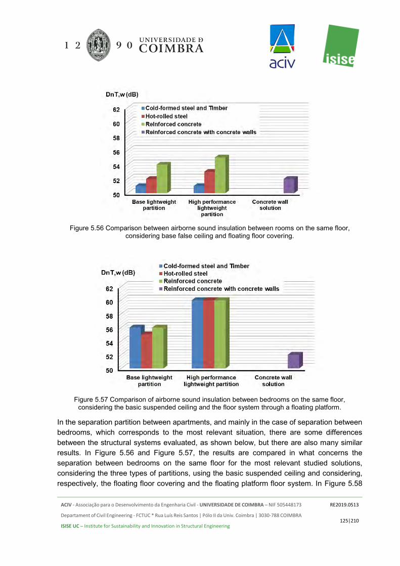
ACIV - Associação para o Desenvolvimento da Engenharia Civil - UNIVERSIDADE DE COIMBRA – NIF 505448173
Departament of Civil Engineering - FCTUC * Rua Luís Reis Santos | Pólo II da Univ. Coimbra | 3030-788 COIMBRA
ISISE UC – Institute for Sustainability and Innovation in Structural Engineering
RE2019.0513
125|210
Figure 5.56 Comparison between airborne sound insulation between rooms on the same floor,
considering base false ceiling and floating floor covering.
Figure 5.57 Comparison of airborne sound insulation between bedrooms on the same floor,
considering the basic suspended ceiling and the floor system through a floating platform.
In the separation partition between apartments, and mainly in the case of separation between bedrooms, which corresponds to the most relevant situation, there are some differences between the structural systems evaluated, as shown below, but there are also many similar results. In Figure 5.56 and Figure 5.57, the results are compared in what concerns the separation between bedrooms on the same floor for the most relevant studied solutions, considering the three types of partitions, using the basic suspended ceiling and considering, respectively, the floating floor covering and the floating platform floor system. In Figure 5.58

ACIV - Associação para o Desenvolvimento da Engenharia Civil - UNIVERSIDADE DE COIMBRA – NIF 505448173
Departament of Civil Engineering - FCTUC * Rua Luís Reis Santos | Pólo II da Univ. Coimbra | 3030-788 COIMBRA
ISISE UC – Institute for Sustainability and Innovation in Structural Engineering
RE2019.0513
126|210
and Figure 5.59, results of the same type are presented, but now considering the separation between adjacent bedrooms of different floors (for the three types of false ceilings).
Figure 5.58 Comparison of airborne sound insulation of floors between adjacent bedrooms,
considering the floating floor covering and three types of false ceilings.
With respect to the transmission of impact noise, and considering the separation between apartments of the same floor, the result depends essentially on the base (resilient material) of the floor covering. In the vertical transmission from an upper floor to a lower floor, the result depends mainly on the resilient material of the floor covering and on the type of suspended ceiling adopted. In Figure 5.60, results are compared for the separation between rooms on the same floor for the most relevant studied solutions, considering the basic partition and the simpler suspended ceiling, and varying the floor base types (in the case of floating floor the solution of layer of 8 mm thickness was considered in all cases). In Figures Figure 5.61, similar results are presented, but now for the separation between adjacent bedrooms of different floors (for the simpler and for the best suspended ceiling solution).

ACIV - Associação para o Desenvolvimento da Engenharia Civil - UNIVERSIDADE DE COIMBRA – NIF 505448173
Departament of Civil Engineering - FCTUC * Rua Luís Reis Santos | Pólo II da Univ. Coimbra | 3030-788 COIMBRA
ISISE UC – Institute for Sustainability and Innovation in Structural Engineering
RE2019.0513
127|210
Figure 5.59 Comparison of airborne sound insulation of floors between adjacent bedrooms,
considering the floating floor platform and two types of suspended ceilings (extreme situations).
Figure 5.60 Comparison between results of the impact noise transmission between bedrooms on the
same floor, considering the basic suspended ceiling and the basic partition.

ACIV - Associação para o Desenvolvimento da Engenharia Civil - UNIVERSIDADE DE COIMBRA – NIF 505448173
Departament of Civil Engineering - FCTUC * Rua Luís Reis Santos | Pólo II da Univ. Coimbra | 3030-788 COIMBRA
ISISE UC – Institute for Sustainability and Innovation in Structural Engineering
RE2019.0513
128|210
Figure 5.61 Comparison between results of the impact noise transmission, between bedrooms of
different floors, considering the basic partition.
In the separation between common circulation zones and the adjacent rooms the results depend heavily on the access doors, and not so much on the structural building solution, as shown in the results presented in the Figure 5.62. Although for the door with higher performance some slight differences can be seen (approximately. 1 dB), it should be noted that for the door with Rw = 40 dB, the acoustic performance is always limited to 49 dB, since the door itself is the limiting factor. Although these results were obtained for the basic partition and for the basic suspended ceiling, no significant changes occur if these elements are improved.
For the transmission of impact noise, and for the separation between common circulation zones and living rooms, the acoustic performance also depends essentially on the resilient solution used under the floor covering, as can be seen in Figure 5.63 (for the basic partition and suspended ceiling solutions). Since two different resilient layer thicknesses were considered (4 and 8 mm), results for these two thicknesses are evaluated. In the presented plot, it can be seen that the lighter structures lead to a somewhat worse performance; this behaviour was expected, since the slabs used in those structures are thinner and lighter. However, it should be noted that it is relatively simple to achieve good performance by adopting improvement measures for all analysed structures.
In what concerns the transmission of impact noise between compartments of the same apartment, the result also depends essentially on the base resilient material used under the floor covering, as can be seen in Figure 5.65 (for the basic suspended ceiling solution).

ACIV - Associação para o Desenvolvimento da Engenharia Civil - UNIVERSIDADE DE COIMBRA – NIF 505448173
Departament of Civil Engineering - FCTUC * Rua Luís Reis Santos | Pólo II da Univ. Coimbra | 3030-788 COIMBRA
ISISE UC – Institute for Sustainability and Innovation in Structural Engineering
RE2019.0513
129|210
Figure 5.62 Comparison of airborne sound insulation between common circulation areas and adjacent
living rooms, considering the basic partition and suspended ceiling, for two types of doors and two types of floor improvement solutions.
Figure 5.63 Comparison between results of the transmission of impact noise, between common
circulation zones and adjacent living rooms, considering the basic suspended ceiling and the basic partition configuration.
In the interior wall partitions of each apartment, in general, it is possible to obtain good performance in any of the evaluated solutions, but there are still some differences among the analysed solutions, as shown in Figure 5.64.
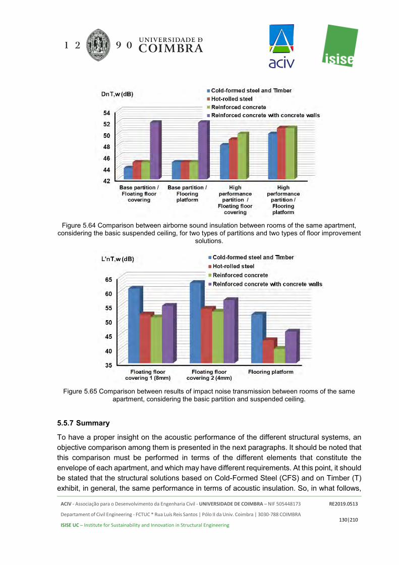
ACIV - Associação para o Desenvolvimento da Engenharia Civil - UNIVERSIDADE DE COIMBRA – NIF 505448173
Departament of Civil Engineering - FCTUC * Rua Luís Reis Santos | Pólo II da Univ. Coimbra | 3030-788 COIMBRA
ISISE UC – Institute for Sustainability and Innovation in Structural Engineering
RE2019.0513
130|210
Figure 5.64 Comparison between airborne sound insulation between rooms of the same apartment,
considering the basic suspended ceiling, for two types of partitions and two types of floor improvement solutions.
Figure 5.65 Comparison between results of impact noise transmission between rooms of the same
apartment, considering the basic partition and suspended ceiling.
5.5.7 Summary
To have a proper insight on the acoustic performance of the different structural systems, an objective comparison among them is presented in the next paragraphs. It should be noted that this comparison must be performed in terms of the different elements that constitute the envelope of each apartment, and which may have different requirements. At this point, it should be stated that the structural solutions based on Cold-Formed Steel (CFS) and on Timber (T) exhibit, in general, the same performance in terms of acoustic insulation. So, in what follows,

ACIV - Associação para o Desenvolvimento da Engenharia Civil - UNIVERSIDADE DE COIMBRA – NIF 505448173
Departament of Civil Engineering - FCTUC * Rua Luís Reis Santos | Pólo II da Univ. Coimbra | 3030-788 COIMBRA
ISISE UC – Institute for Sustainability and Innovation in Structural Engineering
RE2019.0513
131|210
only the CFS solution will be mentioned, being the conclusions for this system also valid for the Timber solution.
Regarding the façade, the final performance depends essentially on the performance of the windows, being almost independent of the type of structure and only slightly dependent of the type of façade wall. For windows with an index Rw + Ctr ≥ 34 dB, which can be achieved with an adequate frame (i.e. presenting a low air permeability behaviour) and with a double glazing, for example one laminated glass with thickness 8.8 mm (of type 44.2), air gap with thickness not bellow 14 mm and second glass with thickness above 6 mm, it is possible to achieve a global insulation D2m, nT, w + Ctr of at least 40 dB in the rooms (worst case scenario).
In what concerns the separation between rooms on the same floor, it was possible to conclude that only in the case in which basic solutions are used for the floating floor and suspended ceiling some differences are observed. Indeed, for that case, a small advantage is registered for the Reinforced Concrete (RC) solution, with slightly smaller sound insulation being registered for the CFS although still reaching a “Sufficient” level. If a platform solution is applied to the floor, the variation of results between the different types of structures is very small, with all of them achieving an "Excellent" performance level if high performance partition solutions are used between rooms.
For the separation between rooms of different floors, the very high mass of the slabs used in the RC solution and even in the Hot-Rolled Steel (HRS) solution present some advantages, both in terms of the airborne and impact sound insulation, particularly when only basic solutions are used for the floor and ceiling; even for that case, the adoption of those basic solutions allows the CFS to clearly exceed the “Sufficient” performance level. Making use of a flooring platform can, again, clearly improve the performance of all solutions, allowing all of them to reach an “Excellent” performance even if a basic ceiling is used.
In the separation between common areas and living rooms, as the airborne sound insulation also depends essentially on the type of door used, the results obtained are almost the same for all types of structures. In what concerns the insulation to impact noise, once again the high mass of the RC structure allows this solution to have a better performance if only basic solutions are used. However, the use of a flooring platform makes it possible to achieve an "Excellent" performance level for any of the analysed structural systems. It should be noted that the CFS solution is much lighter, with thinner slabs, than the other tested solutions; although the bare structure does not reveal the same level of insulation, it is quite simple to improve its performance using standard solutions.
Between compartments of the same housing, the final result depends essentially on the partition and the type of floor covering, and it is not very much influenced by the type of structure. Using high performance partitions or concrete partitions (in the case of Reinforced concrete with concrete walls - RCW), it is possible to reach a Good performance level, or even

ACIV - Associação para o Desenvolvimento da Engenharia Civil - UNIVERSIDADE DE COIMBRA – NIF 505448173
Departament of Civil Engineering - FCTUC * Rua Luís Reis Santos | Pólo II da Univ. Coimbra | 3030-788 COIMBRA
ISISE UC – Institute for Sustainability and Innovation in Structural Engineering
RE2019.0513
132|210
an "Excellent" level (usually with a flooring platform), although with a much lighter and more versatile solution in the first case.
Overall, it becomes evident that the much heavier RC and even the HRS structures may present some advantages in terms of bare structure performance, when no other additional constructive solutions are used. However, it must be stated that this does not correspond to a realistic situation, and indeed that would not allow fulfilling the lowest comfort requirements for building users. In fact, when constructive solutions related to the implementation of suspended ceilings or to floating floors are considered (which are nowadays widespread solutions in many residential buildings), all solutions can reach satisfactory performance levels. Simple and common acoustic engineering solutions can even allow the different configurations to reach excellent performance levels, and it can be said that the most lightweight solutions (particularly CFS) allow excellent insulation levels to be obtained, with a globally much lower mass.
5.6 STRUCTURAL FIRE DESIGN
5.6.1 General Considerations
Fire safety engineering is a key topic in the overall safety of the built environment providing technological solutions capable of minimizing risks and improving safety in case of fire. Protecting a building involves both active and passive protection systems. The passive protection systems are deeply connected to the selection of the building materials, dimensions of the building components, compartmentation and finally to the selected fire protection materials. The passive protection system will control the fire spread and will ensure adequate fire resistance endurance, preventing loss of structural stability.
Structural fire safety design has received greater attention in the past few decades due to continuous loss of properties and in the worst-case scenario loss of lives. This specific area is vital to guarantee adequate evacuation times, minimum safety conditions to firefighters, as well as to minimize property, economic and live losses.
Specifically, for the current case study all structural solutions tested are assessed in terms of its fire resistance, in order to comply with the legislation requirements. For a residential 4 storey building the performance requirement to be fulfilled in terms of fire resistance is 60 minutes both in terms of load bearing capacity for the structural members and thermal insulation and integrity for compartmentation purposes. For compartmentation the 60 minutes of fire resistance (Integrity and Insulation), must be satisfied in the wall facades, between floor levels, between apartments, between the apartments and vertical and horizontal escape routes and in the elevator shaft.

ACIV - Associação para o Desenvolvimento da Engenharia Civil - UNIVERSIDADE DE COIMBRA – NIF 505448173
Departament of Civil Engineering - FCTUC * Rua Luís Reis Santos | Pólo II da Univ. Coimbra | 3030-788 COIMBRA
ISISE UC – Institute for Sustainability and Innovation in Structural Engineering
RE2019.0513
133|210
In the following sub-chapters, the adopted solutions to satisfy the REI 60 criteria for each one of the structural systems investigated will be detailed. Additional comparisons will be established between all of them, identifying the protection needs for each one the solutions.
5.6.2 Cold-Formed Steel
It is well accepted that the fire resistance of unprotected CFS members is very low due to high section factor and high thermal conductivity of steel. Hence, in light steel framing (LSF) fire resistant plasterboards are usually used to protect structural members. Therefore, lightweight steel framing solutions, using cold-formed steel profiles usually present a good fire resistance since passive fire protection is always used considering a few layers of gypsum boards or calcium silicate boards, depending on their thickness and thermal conductivity, which are able to provide fire resistance periods of more than 60 minutes. Many different cladding solutions with fire resistant properties can be prescribed for this type of construction, including PPF BA, STD BA HBT and GLASROC X gypsum boards from Saint-Gobain, for instance. In Annex A some solutions are presented for both facades and internal partitions. Since all walls have load bearing function and considering the target of 60 minutes of fire resistance, two 12.5 mm gypsum boards should be used, as it can be checked by Figure 5.66. Taking advantage of advance calculation tools (Finite Element Method) it is possible to assess the structural fire behavior of a protected cold-formed steel member in fire situation. Sequential heat transfers and structural analysis were undertaken, considering the ISO 834 standard fire curve. As it can be observed two 12.5 mm gypsum boards are enough to fulfill the fire resistance requirement of 60 minutes. For suspended floor ceilings, two 12.5 mm boards should also be used.
It is worth mentioning that based on the commercially available products it is possible to select gypsum boards for general building applications and fire protection (e.g.: Glasroc F Multiboard) or specific gypsum boards for fire protection purposes (e.g.: Glasroc X Sheathing Board and Glasroc F firecase). If the Glasroc X Sheathing Board is selected two 12.5 mm gypsum boards should be used, whereas if the Glasroc F Firecase is selected it is possible to adopt a single board, since these are manufactured in thicknesses ranging from 15 to 30 mm. Hence, a 25 mm single board can be prescribed, minimizing labour and execution times.
In Figure 5.67 and Figure 5.68 all quantities required for fire protection (to satisfy the REI 60 criteria) of such building solution with gypsum boards from Saint-Gobain are presented, both for the commonly used system, CUS (Figure 5.67), and for the high performance system, HPS (Figure 5.68). Specifically, for the cold-formed steel building and since all external and internal walls are load bearing all fire resistance criteria must be satisfied (REI) by the implemented solution.

ACIV - Associação para o Desenvolvimento da Engenharia Civil - UNIVERSIDADE DE COIMBRA – NIF 505448173
Departament of Civil Engineering - FCTUC * Rua Luís Reis Santos | Pólo II da Univ. Coimbra | 3030-788 COIMBRA
ISISE UC – Institute for Sustainability and Innovation in Structural Engineering
RE2019.0513
134|210
Figure 5.66 Structural fire behavior of a CFS member in compression and exposed to fire during 60 minutes: a) temperature distribution; b and c) deformed configuration; d) axial displacement as a
function of time.
Despite the need of passive fire protection lightweight steel frame construction still presents some relevant advantages over other types of construction. For instance, comparing directly with timber framed solutions, steel is non-combustible and does not add fire load to the building, consequently, does not contribute to the fire spread. Moreover, it can be stated that framing solutions using steel are safer during the construction stage, since it is a non-combustible material, and in case of small fires (typical situation in residential buildings) repairs are usually much easier and inexpensive.

ACIV - Associação para o Desenvolvimento da Engenharia Civil - UNIVERSIDADE DE COIMBRA – NIF 505448173
Departament of Civil Engineering - FCTUC * Rua Luís Reis Santos | Pólo II da Univ. Coimbra | 3030-788 COIMBRA
ISISE UC – Institute for Sustainability and Innovation in Structural Engineering
RE2019.0513
135|210
Figure 5.67 Estimated quantities of gypsum boards from Saint-Gobain for the commonly used CFS solution
Figure 5.68 Estimated quantities of gypsum boards from Saint-Gobain for the high performance CFS solution
5.6.3 Hot-Rolled Steel
Steel has high thermal conductivity and specific heat, meaning that the temperature will rise very fast in a cross-section. Moreover, the mechanical properties of steel degrade with temperature increase. For instance, at 600ºC the reduction of the yield strength of the steel is more than 50%, whereas the modulus of elasticity reduced by 70%.

ACIV - Associação para o Desenvolvimento da Engenharia Civil - UNIVERSIDADE DE COIMBRA – NIF 505448173
Departament of Civil Engineering - FCTUC * Rua Luís Reis Santos | Pólo II da Univ. Coimbra | 3030-788 COIMBRA
ISISE UC – Institute for Sustainability and Innovation in Structural Engineering
RE2019.0513
136|210
Nowadays, the most common solution to protect steel structures is the use of intumescent paints applied on-site or in the workshop. In this case, the beams and columns obtained from structural analysis at ambient temperature, an intumescent coating with a dry film thickness of 1000 𝜇𝑚 should be used for 60 minutes of fire resistance, since their section factors range from 150 to 200 𝑚−1.
However, for the current case study, and considering the type of partitioning solutions, Saint Gobain products were selected to protect the steel structural elements. For the hot-rolled steel building the structural elements (columns and beams) and compartmentation walls must be protected. For compartmentation purposes (Integrity and Insulation (EI)) and just like for the cold-formed steel building the same areas must be adequately protected, specifically between floor levels, in the facades, between apartments, between apartments and the elevator shafts and between apartments and horizontal and vertical escape routes. In terms of load bearing capacity (R) the steel columns and beams will also be protected considering a box protection using gypsum boards.
For the steel structural elements (columns and beams) the encasement is achieved by using 15 mm gypsum boards, specifically Glasroc F Firecase. For the beams only three sides are protected, since the composite slab is positioned on the top flange of the beam.
For compartmentation, for facades, between apartments, between floors, and between apartments and horizontal and vertical escape routes, two 12.5 mm gypsum boards may be used or alternatively, one Glasroc F Firecase with 25 mm (acoustic performance were also considered here). Adopting a single board may lead to a reduction in the execution time. For the composite slabs no specific protection is needed in terms of integrity and insulation (EI).
Figure 5.69 and Figure 5.70 include the quantities required for fire protection of such building solution with gypsum boards from Saint-Gobain, both for the commonly used system, CUS (Figure 5.69), and for the high-performance system, HPS (Figure 5.70). Figure 5.71 Estimated quantities of gypsum boards from Saint-Gobain for the commonly used HRS solution still shows the reduction of the gypsum boards if intumescent paint is used on the beams.
On the other hand, if tensile membrane action is taken into account in the composite slabs, the beams 1E-4E, 1F-4F, 6E-9E, 6F-9F, 2A-2B and 8A-8B (Figure 4.6) do not need fire protection. However, the minimum required slab thickness is 14 cm, so that the thermal insulation separating function is checked (Figure 5.72).

ACIV - Associação para o Desenvolvimento da Engenharia Civil - UNIVERSIDADE DE COIMBRA – NIF 505448173
Departament of Civil Engineering - FCTUC * Rua Luís Reis Santos | Pólo II da Univ. Coimbra | 3030-788 COIMBRA
ISISE UC – Institute for Sustainability and Innovation in Structural Engineering
RE2019.0513
137|210
Figure 5.69 Estimated quantities of gypsum boards from Saint-Gobain for the commonly used HRS solution
Figure 5.70 Estimated quantities of gypsum boards from Saint-Gobain for the high performance HRS solution

ACIV - Associação para o Desenvolvimento da Engenharia Civil - UNIVERSIDADE DE COIMBRA – NIF 505448173
Departament of Civil Engineering - FCTUC * Rua Luís Reis Santos | Pólo II da Univ. Coimbra | 3030-788 COIMBRA
ISISE UC – Institute for Sustainability and Innovation in Structural Engineering
RE2019.0513
138|210
Figure 5.71 Estimated quantities of gypsum boards from Saint-Gobain for the commonly used HRS solution
Figure 5.72 Structural fire behavior of a composite slab under fire during 60 minutes (MACS+ software)

ACIV - Associação para o Desenvolvimento da Engenharia Civil - UNIVERSIDADE DE COIMBRA – NIF 505448173
Departament of Civil Engineering - FCTUC * Rua Luís Reis Santos | Pólo II da Univ. Coimbra | 3030-788 COIMBRA
ISISE UC – Institute for Sustainability and Innovation in Structural Engineering
RE2019.0513
139|210
5.6.4 Reinforced Concrete
Reinforced concrete has very good behavior when exposed to fire. Just like steel is non-combustible and does not contribute to fire spread, however, unlike steel, has high section factor, and low thermal conductivity. This will significantly slow down the rate of temperature increase in a reinforced concrete cross-section. To meet the required fire resistance of R60 for the studied building simplified calculation methods and tabulated data were used to check the safety of the different structural elements. The tabulated data is based on empirical data, combined with evaluation of test results. The tabulated data provide minimal dimensions of the cross-section and minimum distance of the reinforcement until the concrete surface on the safe side. Reinforced concrete solutions presented in this study will not require additional fire protection to meet the 60 minutes requirements in terms of load bearing capacity (R). However, for compartmentation purposes, the wall systems prescribed for this solution and detailed in 8.ANNEX A were used, just like for the other framing solutions (Figure 5.73 and Figure 5.74).
Figure 5.73 - Estimated quantities of gypsum boards from Saint-Gobain for the commonly used RC solution

ACIV - Associação para o Desenvolvimento da Engenharia Civil - UNIVERSIDADE DE COIMBRA – NIF 505448173
Departament of Civil Engineering - FCTUC * Rua Luís Reis Santos | Pólo II da Univ. Coimbra | 3030-788 COIMBRA
ISISE UC – Institute for Sustainability and Innovation in Structural Engineering
RE2019.0513
140|210
Figure 5.74 - Estimated quantities of gypsum boards from Saint-Gobain for the high performance RC solution
5.6.5 Timber
Fire resistance is one of the most important requirements to address for a structure. Just like for the other framing solutions the required fire resistance for the studied building is 60 minutes, both in terms of load bearing capacity (R), integrity (E) and thermal insulation (I). Timber is actually a material with good fire resistance since it burns in a controlled way and dependent on the charring rate which generally can be considered as 0.7-0.8 mm/min for solid timber members. For large cross-sections, the slow charring rate can ensure that the required fire resistance is met. However, for the studied building the cross-sections are relatively small, consequently, to meet the required 60 minutes of fire resistance, only one 12.5 mm gypsum board shall be used in terms of load bearing capacity in all members (columns and floors). However, for the facades and internal partitioning walls the same wall system proposed by Saint-Gobain should be used to ensure that the structure is able to fulfil the requirements in terms of fire resistance (REI60). Hence, Figure 5.75 and Figure 5.76 include the quantities required for fire protection of such building solution with gypsum boards from Saint-Gobain, both for the commonly used system, CUS (Figure 5.75), and for the high performance system, HPS (Figure 5.76). The fire protection system is almost identical to the one prescribed to the cold-formed steel building, however the thickness of the protection material can be reduced.

ACIV - Associação para o Desenvolvimento da Engenharia Civil - UNIVERSIDADE DE COIMBRA – NIF 505448173
Departament of Civil Engineering - FCTUC * Rua Luís Reis Santos | Pólo II da Univ. Coimbra | 3030-788 COIMBRA
ISISE UC – Institute for Sustainability and Innovation in Structural Engineering
RE2019.0513
141|210
Figure 5.75 - Estimated quantities of gypsum boards from Saint-Gobain for the commonly used T solution
Figure 5.76 - Estimated quantities of gypsum boards from Saint-Gobain for the high performance T solution
5.6.6 Comparison Between the Proposed Solutions
As expected, the solution with less fire protection material is the reinforced concrete one, followed by the hot-rolled steel, timber and finally the cold-formed steel (CFS) solution, hence the reinforced concrete solution is the best solution when the fire resistance criteria is being assessed.

ACIV - Associação para o Desenvolvimento da Engenharia Civil - UNIVERSIDADE DE COIMBRA – NIF 505448173
Departament of Civil Engineering - FCTUC * Rua Luís Reis Santos | Pólo II da Univ. Coimbra | 3030-788 COIMBRA
ISISE UC – Institute for Sustainability and Innovation in Structural Engineering
RE2019.0513
142|210
Comparing to the light steel framing building, a reduction of 32, 56 and 62% in the amount of gypsum boards can be achieved respectively for the fire protection of the timber, hot-rolled steel and reinforced concrete structural solutions (Figure 5.77).
Figure 5.77 - Estimated quantities of gypsum boards from Saint-Gobain for all type of solutions
The differences in terms of passive protection needs are mainly due to the fact that the structural elements must be protected in order to fulfill the fire resistance requirements for this building. For compartmentation purposes the protection needs are quite similar for the reinforced concrete and hot-rolled steel building, since similar partitioning solutions are considered. For the hot-rolled steel building additional protection is required for the structural elements (columns and beams).
For the cold-formed steel building all internal and external walls are load bearing, consequently all walls are protected so that the load bearing criteria (R60) may be satisfied. For the timber building the total amount of passive protection is smaller than for the cold-formed steel building because only one board is required to fulfill the R60 criteria, and in some internal walls the EI60 criteria is not required.
Despite the fact the extra weight in fire protection it is worth mentioning that the cold-formed steel building is able to fulfill all the fire resistance requirements. Moreover, the amount of combustible material is much lower than in timber buildings. Safe solutions can be defined using passive fire protection and at some extent it can be added that in the internal partitions additional safety levels may be achieved since all partitions ensure fire resistance in terms of load-bearing capacity (R), integrity (E) and insulation (I). Hence, cold-formed steel framing solutions provide great safety levels.

ACIV - Associação para o Desenvolvimento da Engenharia Civil - UNIVERSIDADE DE COIMBRA – NIF 505448173
Departament of Civil Engineering - FCTUC * Rua Luís Reis Santos | Pólo II da Univ. Coimbra | 3030-788 COIMBRA
ISISE UC – Institute for Sustainability and Innovation in Structural Engineering
RE2019.0513
143|210
6. CONSTRUCTION SCHEDULE
6.1 INTRODUCTION
The construction schedule is a very important parameter that may influence the selection of the framing material to be adopted. Faster construction programmes will lead to an earlier use/exploitation of the building which can be translated into earlier use/rental income. A detailed analysis of each framing option was undertaken, aiming to establish a comparison between the estimated construction durations for the different structural materials. In this assessment, both frame and whole building construction durations were considered. In this analysis, the construction schedule is not dependent on-site location.
For the cold-formed, hot-rolled steel and timber solutions it is assumed that all parts to be fabricated in a workshop will be available in the construction site as soon as needed. Hence, with proper planning, the fabrication in a workshop of the structural elements for the cold-formed, hot-rolled and timber building will not impact the planning of the construction site. The possibility of pre-fabrication brings some inherent advantages, such as:
• prefabrication techniques will allow the development of more technologically advanced solutions (depending on the workshop equipment and manpower);
• industrialization of the fabrication process will ensure faster execution times and safer working conditions (depending on the workshop equipment and manpower);
• increased productivity using prefabricated elements; • higher overall quality of the final product (quality control is easier to implement in a
controlled environment such as a workshop); • reduction of site activities for frame erection, increasing safety levels; • lower on-site work is translated into lower on-site construction waste, and even some
of the steel waste can be recycled and reused; • prefabricated solutions such as steel and timber buildings, generates flexible solutions,
and specifically for residential buildings, the possibility to easily reshape the interior of the building can be an important advantage;
• Prefabricated solutions and specifically the cold-formed and hot-rolled steel ones may present an enhanced future-proofing (longer life for the building) due to its better adaptability and possibility for expansion which allow for easier changes in the future in order to address new service requirements;
• Greater possibility of disassembly, re-use and relocation of the building; • within the prefabricated solutions (cold-formed, hot-rolled steel and timber) steel
presents some advantages when comparing with timber, namely, non-combustibility, termite-proof and rot proof, straightness, the accuracy of cutting and profiles. Steel will not shrink, split, warp, crack and creep;
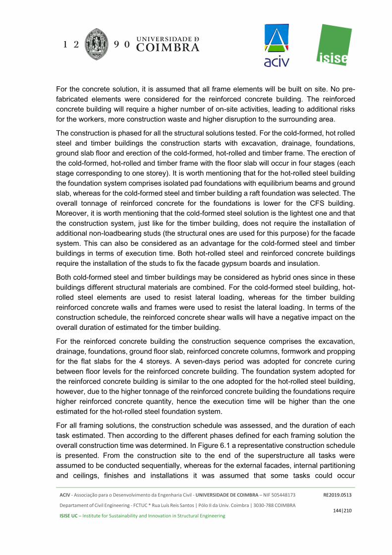
ACIV - Associação para o Desenvolvimento da Engenharia Civil - UNIVERSIDADE DE COIMBRA – NIF 505448173
Departament of Civil Engineering - FCTUC * Rua Luís Reis Santos | Pólo II da Univ. Coimbra | 3030-788 COIMBRA
ISISE UC – Institute for Sustainability and Innovation in Structural Engineering
RE2019.0513
144|210
For the concrete solution, it is assumed that all frame elements will be built on site. No pre-fabricated elements were considered for the reinforced concrete building. The reinforced concrete building will require a higher number of on-site activities, leading to additional risks for the workers, more construction waste and higher disruption to the surrounding area.
The construction is phased for all the structural solutions tested. For the cold-formed, hot rolled steel and timber buildings the construction starts with excavation, drainage, foundations, ground slab floor and erection of the cold-formed, hot-rolled and timber frame. The erection of the cold-formed, hot-rolled and timber frame with the floor slab will occur in four stages (each stage corresponding to one storey). It is worth mentioning that for the hot-rolled steel building the foundation system comprises isolated pad foundations with equilibrium beams and ground slab, whereas for the cold-formed steel and timber building a raft foundation was selected. The overall tonnage of reinforced concrete for the foundations is lower for the CFS building. Moreover, it is worth mentioning that the cold-formed steel solution is the lightest one and that the construction system, just like for the timber building, does not require the installation of additional non-loadbearing studs (the structural ones are used for this purpose) for the facade system. This can also be considered as an advantage for the cold-formed steel and timber buildings in terms of execution time. Both hot-rolled steel and reinforced concrete buildings require the installation of the studs to fix the facade gypsum boards and insulation.
Both cold-formed steel and timber buildings may be considered as hybrid ones since in these buildings different structural materials are combined. For the cold-formed steel building, hot-rolled steel elements are used to resist lateral loading, whereas for the timber building reinforced concrete walls and frames were used to resist the lateral loading. In terms of the construction schedule, the reinforced concrete shear walls will have a negative impact on the overall duration of estimated for the timber building.
For the reinforced concrete building the construction sequence comprises the excavation, drainage, foundations, ground floor slab, reinforced concrete columns, formwork and propping for the flat slabs for the 4 storeys. A seven-days period was adopted for concrete curing between floor levels for the reinforced concrete building. The foundation system adopted for the reinforced concrete building is similar to the one adopted for the hot-rolled steel building, however, due to the higher tonnage of the reinforced concrete building the foundations require higher reinforced concrete quantity, hence the execution time will be higher than the one estimated for the hot-rolled steel foundation system.
For all framing solutions, the construction schedule was assessed, and the duration of each task estimated. Then according to the different phases defined for each framing solution the overall construction time was determined. In Figure 6.1 a representative construction schedule is presented. From the construction site to the end of the superstructure all tasks were assumed to be conducted sequentially, whereas for the external facades, internal partitioning and ceilings, finishes and installations it was assumed that some tasks could occur

ACIV - Associação para o Desenvolvimento da Engenharia Civil - UNIVERSIDADE DE COIMBRA – NIF 505448173
Departament of Civil Engineering - FCTUC * Rua Luís Reis Santos | Pólo II da Univ. Coimbra | 3030-788 COIMBRA
ISISE UC – Institute for Sustainability and Innovation in Structural Engineering
RE2019.0513
145|210
simultaneously but in different levels in the building. For instance, fitting the internal partitions will start when the external facades are fitted up to the third storey of the building. The same assumption was adopted for the remaining tasks and for all framing solutions investigated. Hence, it is assumed that overlapping activities will not be advantageous for any of the tested solutions.
Figure 6.1.Representative construction schedule.
6.2 COMPARISON OF THE CONSTRUCTION SCHEDULES
To understand and detail the main differences between the 7 tested framing solutions the estimated execution programmes were compared by activity. As depicted in Figure 6.1 the construction schedule was divided into 7 main activities, namely: (i) construction site; (ii) groundworks, foundations and ground slab; (iii) superstructure and roof; (iv) external facades; (v) internal partitioning and ceilings; (vi) finishes; and (vii) installations. In Table 6.1 and Table 6.2 the estimated construction schedules are compared for each major activity. Graphically the obtained results are presented in Figure 6.2 and Figure 6.3.
Table 6.1. Detailed construction schedule for all tested framing solutions and the reference situation. Reference case
Activity RC HRS CFS Timber HRS CFS RC Construction site [days] 15 8 8 8 8 8 15
Foundation [days] 32 28 18 19 28 18 18 Superstructure [days] 99 76 67 112 84 71 87
External facades [days] 62 62 41 46 62 41 47 Internal partitioning +
ceilings [days] 94 94 64 76 94 64 54
Installations [days] 60 60 60 60 60 60 60 Finishes [days] 65 65 65 65 65 65 65
Table 6.2. Detailed construction schedule for all tested framing solutions and high seismic situation.
Total duration [weeks]Activity
Construction siteGroundworks, foundations and ground slabSuperstructure + roof worksExternal facadesInternal partitioningInstallationsFinishes
Building type8035 40 45 50 55 605 10 15 20 25 30 65 70 75

ACIV - Associação para o Desenvolvimento da Engenharia Civil - UNIVERSIDADE DE COIMBRA – NIF 505448173
Departament of Civil Engineering - FCTUC * Rua Luís Reis Santos | Pólo II da Univ. Coimbra | 3030-788 COIMBRA
ISISE UC – Institute for Sustainability and Innovation in Structural Engineering
RE2019.0513
146|210
High-Seismic case Activity RC HRS CFS Timber HRS CFS RC
Construction site [days] 15 8 8 8 8 8 15 Foundation [days] 34 31 18 19 31 18 19
Superstructure [days] 111 86 84 114 87 72 90 External facades [days] 62 62 41 46 62 41 47 Internal partitioning +
ceilings [days] 94 94 64 76 94 64 54
Installations [days] 60 60 60 60 60 60 60 Finishes [days] 65 65 65 65 65 65 65
Figure 6.2. Comparison of the construction schedule per activity, for the reference case.
Figure 6.3. Comparison of the construction schedule per activity, for the high seismic case.
In terms of percentage, the obtained results are detailed in Table 6.3 and Table 6.4.
0
25
50
75
100
125
Dur
atio
n [d
ays]
Construction site FoundationSuperstructure External facadesInternal partitioning + ceilings InstallationsFinishes
0
25
50
75
100
125
Dur
atio
n [d
ays]
Construction site FoundationSuperstructure External facadesInternal partitioning + ceilings InstallationsFinishes

ACIV - Associação para o Desenvolvimento da Engenharia Civil - UNIVERSIDADE DE COIMBRA – NIF 505448173
Departament of Civil Engineering - FCTUC * Rua Luís Reis Santos | Pólo II da Univ. Coimbra | 3030-788 COIMBRA
ISISE UC – Institute for Sustainability and Innovation in Structural Engineering
RE2019.0513
147|210
Table 6.3. Percentage of reduction/increase in the construction time for each framing type considering the reinforced concrete solution.as reference – Reference case - no seismic action.
Reference case
Activity RC / HRS
[%] RC / CFS
[%]
RC / Timber
[%]
RC_SW / HRS_RC
[%]
RC_SW / CFS_RC
[%] Construction site 47 47 47 47 47
Foundation 13 44 41 -56 0 Superstructure 23 32 -12 3 18
External facades 0 34 26 -32 13 Internal partitioning + ceilings 0 32 19 -74 -19
Finishes 0 0 0 0 0 Installations 0 0 0 0 0
Table 6.4. Percentage of reduction/increase in the construction time for each framing type considering the reinforced concrete solution.as reference – High Seismicity location.
Reference case
Activity RC / HRS
[%] RC / CFS
[%]
RC / Timber
[%]
RC_SW / HRS_RC
[%]
RC_SW / CFS_RC
[%] Construction site 47 47 47 47 47
Foundation 9 47 44 -63 5 Superstructure 23 24 -3 3 20
External facades 0 34 26 -32 13 Internal partitioning + ceilings 0 32 19 -74 -19
Finishes 0 0 0 0 0 Installations 0 0 0 0 0
Comparing the reinforced concrete framing solution with the hot-rolled steel one (Ref. – no-seismic action; HS – high seismicity level) it was found that:
• the foundation system for the HRS building takes 13% (9% for the high seismic case) less time to be built;
• The foundation of the RC solution with concrete walls takes much shorter due to the difference of the foundation system
• the superstructure for the HRS building takes 23% (23% for the high seismic case) less time to be built.
• the internal partitioning and façade walls in the RC solution with concrete is now faster due to the existence of the walls which only need finishes, unlike the HRS solution where the structure of the walls needs to be constructed first.

ACIV - Associação para o Desenvolvimento da Engenharia Civil - UNIVERSIDADE DE COIMBRA – NIF 505448173
Departament of Civil Engineering - FCTUC * Rua Luís Reis Santos | Pólo II da Univ. Coimbra | 3030-788 COIMBRA
ISISE UC – Institute for Sustainability and Innovation in Structural Engineering
RE2019.0513
148|210
Comparing the reinforced concrete framing solution with the cold-formed steel one (Ref. – no-seismic action; HS – high seismicity level) it was found that:
• the foundation system for the CFS building takes 44% (47% for the high seismic case) less time to be built;
• The foundation of the RC solution with shear wall is equivalent to the CFS and therefore the only difference was found in the high seismic case where the RC solution is heavier;
• the superstructure for the CFS building takes 32% (24% for the high seismic case) less time to be built;
• the external facades for the CFS building take 34% (34% for the high seismic case) less time to be installed;
• the internal partitioning for the CFS building takes 32% (32% for the high seismic case) less time to be installed.
Comparing the reinforced concrete framing solution with the timber one (Ref. – no-seismic action; HS – high seismicity level) it was found that:
• the foundation system for the timber building takes 41% (44% for the high seismic case) less time to be built;
• the superstructure for the timber building takes 12% (3% for the high seismic case) more time to be built;
• the external facades for the timber building take 26% (26% for the high seismic case) less time to be installed;
• the internal partitioning for the timber building takes 19% (19% for the high seismic case) less time to be installed.
Analysing the obtained results, it is clear that for the reference case (no seismic action) the longer construction time estimated for the reinforced concrete building is mainly due to the extra time needed to build the foundations, superstructure, facades and internal partitioning. The extra time needed for the foundations and superstructure is mainly due to the higher weight of the elements as well as due to the extra time required for curing purposes. It is worth mentioning that the construction of the superstructure of the timber building takes longer than the superstructure of the reinforced concrete solution. This is due to the hybrid character of the building (consideration of reinforced concrete shear walls and frames), which also impacts negatively on the overall duration of the construction of the superstructure. Moreover, it was assumed that erection of timber elements takes longer than the erection of steel ones.
The lack of prefabrication leads to a high volume of works in the construction site. Regarding the external facades and internal partitioning, the extra time, just as for the hot-rolled steel solution, is due to the fact that the non-loadbearing wall studs must be positioned first, whereas for the cold-formed steel and timber solutions the load bearing wall studs are also used to fix the wall panels.

ACIV - Associação para o Desenvolvimento da Engenharia Civil - UNIVERSIDADE DE COIMBRA – NIF 505448173
Departament of Civil Engineering - FCTUC * Rua Luís Reis Santos | Pólo II da Univ. Coimbra | 3030-788 COIMBRA
ISISE UC – Institute for Sustainability and Innovation in Structural Engineering
RE2019.0513
149|210
The longer construction schedule was obtained for the reinforced concrete building using frame system, followed by the timber building and hot-rolled steel building while the reinforced concrete solution with concrete walls is compatible in time with the hot-rolled steel and timber solutions. The shortest execution time was obtained for the cold-formed steel building. For each one of the tested cases, the impact of the high seismic action on the execution programmes led to a small increase in the overall time, basically due to the higher quantities of structural materials for both foundations and frames. In Table 6.5 the total duration estimated for the construction schedule is presented for both reference and high seismic situation.
Table 6.5. Execution programme for the reference case and for the high seismic one for all tested framing systems. Reference case
RC HRS CFS Timber HRS_RC CFS_RC RC_SW Duration
[days] 385 351 294 357
359
298
340 High-Seismic case
Duration [days] 399 364 311 359
364
299
344
In this study, the estimated duration for the reinforced concrete building was 77 weeks (385 days) and 68 weeks (340 days) if all walls are executed in concrete, for the hot-rolled steel building was 71 weeks (351 days) and 72 weeks (359 days) with RC core, for the cold-formed steel 59 weeks (294 days) and 60 weeks with RC core (298 days) and for the timber building 73 weeks (357 days). The hot-rolled steel building programme is reduced by 8.8%, the cold-formed steel programme is reduced by 23.6% and the timber building programme is reduced by 7.2% when compared with the reinforced concrete building programme. The RC solution with walls is 5.3% faster than the hot-rolled solution with concrete core and 12.3% slower than the cold-formed building with concrete core.
For the case where the buildings were located in a high seismic area the obtained duration for the reinforced concrete was 80 weeks (399 working days) and 69 weeks (344 days) if all walls are executed in concrete, for the hot-rolled steel was 73 weeks (364 days) and 73 weeks (364 days) with RC core, for the cold-formed steel was 62 weeks (311 days) and 60 weeks with RC core (299 days) and for the timber 72 weeks (359 days). The hot-rolled steel building schedule is reduced by 8.7%, the cold-formed steel programme is reduced by 22% and the timber building programme is reduced by 10% when compared with the reinforced concrete building schedule. The RC solution with walls is 7.0% faster than the hot-rolled solution with concrete core and 12.1% slower than the cold-formed building with concrete core.

ACIV - Associação para o Desenvolvimento da Engenharia Civil - UNIVERSIDADE DE COIMBRA – NIF 505448173
Departament of Civil Engineering - FCTUC * Rua Luís Reis Santos | Pólo II da Univ. Coimbra | 3030-788 COIMBRA
ISISE UC – Institute for Sustainability and Innovation in Structural Engineering
RE2019.0513
150|210
In Figure 6.4 and Figure 6.5 the estimated durations for both reference and high seismic situation are depicted and compared.
Figure 6.4. Estimated total duration for the execution programme for all framing solutions and
reference case.
Figure 6.5. Estimated total duration for the execution programme for all framing solutions and high
seismic case.
For all the tested conditions the use of cold-formed steel for framing always resulted in smaller execution programmes. This is mainly due to the lighter foundations, prefabrication of the elements allowing for a faster superstructure erection, easier and faster wall sheeting assembly, specifically taking into consideration the adopted wall systems.
200
250
300
350
400
450385
351
294
357 359
298340
Dur
atio
n [d
ays]
200
250
300
350
400
450 399364
311
359 364
299
344
Dur
atio
n [d
ays]

ACIV - Associação para o Desenvolvimento da Engenharia Civil - UNIVERSIDADE DE COIMBRA – NIF 505448173
Departament of Civil Engineering - FCTUC * Rua Luís Reis Santos | Pólo II da Univ. Coimbra | 3030-788 COIMBRA
ISISE UC – Institute for Sustainability and Innovation in Structural Engineering
RE2019.0513
151|210
6.3 SITE PLANNING
6.3.1 Organization of the construction site and technology of execution
An important part of the construction process is the planning of the construction site. Since the structures are different, the planning is slightly different for each structural solution. However, in order not to interfere in the final solution the following assumptions were applied:
• Each site will be cleaned and drained before the beginning of the construction; • Each construction site will use tower crane to for lifting of materials during the
construction process; • The crane is installed at the beginning of the construction; • The site has access to the urban road system so that the concreting can be performed
using concrete pump truck and there is sufficient space for the trucks delivering concrete without need of any special permission;
• There is sufficient space for storage;
The chosen arrangements of the construction sites are shown in Figure 6.6 to Figure 6.9 for each structural solution. They all use the same tower crane, the same size of temporary installations, the only difference is found in the storage areas which depend of the size of the stored materials and the duration of the crane and temporary installations renting.
6.3.2 Cold-formed steel solution
The site planning is shown in Figure 6.6. The foundations and floor slabs are executed in concrete and it is assumed that the concreting is performed using a concrete pump truck.
The CFS panels will be delivered on site with dimensions of 3.2 x 1.2 m and mounted on site. The mineral wool and gypsum boards are also mounted on site. For this the CFS construction site will have higher space requirements for storage of the panels. The site needs to be equipped with tower crane which will be used for lifting of the HRS members, CFS panels, steel sheeting, etc.

ACIV - Associação para o Desenvolvimento da Engenharia Civil - UNIVERSIDADE DE COIMBRA – NIF 505448173
Departament of Civil Engineering - FCTUC * Rua Luís Reis Santos | Pólo II da Univ. Coimbra | 3030-788 COIMBRA
ISISE UC – Institute for Sustainability and Innovation in Structural Engineering
RE2019.0513
152|210
Figure 6.6. Construction site planning – CFS solution
6.3.3 Hot-rolled steel solution
The site planning is shown in Figure 6.7. The foundations and floor slabs are executed in concrete and it is assumed that the concreting is performed using a concrete pump truck.
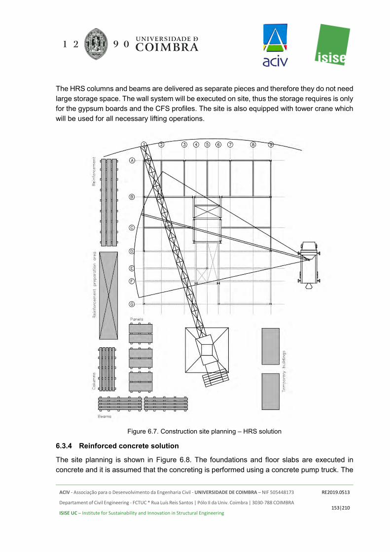
ACIV - Associação para o Desenvolvimento da Engenharia Civil - UNIVERSIDADE DE COIMBRA – NIF 505448173
Departament of Civil Engineering - FCTUC * Rua Luís Reis Santos | Pólo II da Univ. Coimbra | 3030-788 COIMBRA
ISISE UC – Institute for Sustainability and Innovation in Structural Engineering
RE2019.0513
153|210
The HRS columns and beams are delivered as separate pieces and therefore they do not need large storage space. The wall system will be executed on site, thus the storage requires is only for the gypsum boards and the CFS profiles. The site is also equipped with tower crane which will be used for all necessary lifting operations.
Figure 6.7. Construction site planning – HRS solution
6.3.4 Reinforced concrete solution
The site planning is shown in Figure 6.8. The foundations and floor slabs are executed in concrete and it is assumed that the concreting is performed using a concrete pump truck. The
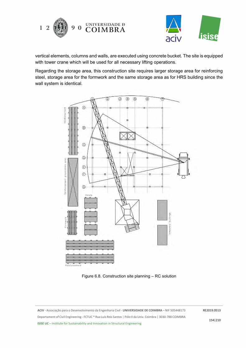
ACIV - Associação para o Desenvolvimento da Engenharia Civil - UNIVERSIDADE DE COIMBRA – NIF 505448173
Departament of Civil Engineering - FCTUC * Rua Luís Reis Santos | Pólo II da Univ. Coimbra | 3030-788 COIMBRA
ISISE UC – Institute for Sustainability and Innovation in Structural Engineering
RE2019.0513
154|210
vertical elements, columns and walls, are executed using concrete bucket. The site is equipped with tower crane which will be used for all necessary lifting operations.
Regarding the storage area, this construction site requires larger storage area for reinforcing steel, storage area for the formwork and the same storage area as for HRS building since the wall system is identical.
Figure 6.8. Construction site planning – RC solution

ACIV - Associação para o Desenvolvimento da Engenharia Civil - UNIVERSIDADE DE COIMBRA – NIF 505448173
Departament of Civil Engineering - FCTUC * Rua Luís Reis Santos | Pólo II da Univ. Coimbra | 3030-788 COIMBRA
ISISE UC – Institute for Sustainability and Innovation in Structural Engineering
RE2019.0513
155|210
6.3.5 Timber solution
The construction site planning is shown in Figure 6.9. The foundations and floor slabs are executed in concrete and it is assumed that the concreting is performed using a concrete pump truck. The vertical elements, columns and walls, are executed using concrete bucket.
Figure 6.9. Construction site planning – Timber solution
The wall panels will be mounted on site together with the mineral wool and gypsum boards. The Timber building construction site will also have higher space requirements for storage of

ACIV - Associação para o Desenvolvimento da Engenharia Civil - UNIVERSIDADE DE COIMBRA – NIF 505448173
Departament of Civil Engineering - FCTUC * Rua Luís Reis Santos | Pólo II da Univ. Coimbra | 3030-788 COIMBRA
ISISE UC – Institute for Sustainability and Innovation in Structural Engineering
RE2019.0513
156|210
the panels. The site needs to be equipped with tower crane which will be used for all necessary lifting operations.
6.3.6 Comparison of the on-site craning costs for all solutions
The on-site craning costs are estimated assuming that the crane will be installed on during the initial set-up of the construction site. Hence the days for site preparation were subtracted from the total construction time.
For the execution of each structural solution it is considered sufficient to use a tower crane with maximum radius of 25.5m and capacity on the tip of 1.5t. The renting cost in Portugal of such crane was estimated to 3000€/month.
The estimated costs are presented in Figure 6.10 for the reference case and in Figure 6.11 for the HS case.
Figure 6.10. On-site craning costs reference solution
The costs are directly proportional to the duration of the construction, and thus the reinforced concrete solutions are generally more expensive than the CFS and HRS solutions. This is also reflected when comparing the reference case and high seismicity case, where higher craning costs will be required due to the longer execution period. Nevertheless, in terms of cost the difference between the reference and HS cases found to be very low, varies between 0 and 6% for the different structural solutions.
0
10000
20000
30000
40000
50000
60000
39 000 €46 773 €50 455 €47 591 €
39 545 €47 864 €44 318 €
Cos
t [€]

ACIV - Associação para o Desenvolvimento da Engenharia Civil - UNIVERSIDADE DE COIMBRA – NIF 505448173
Departament of Civil Engineering - FCTUC * Rua Luís Reis Santos | Pólo II da Univ. Coimbra | 3030-788 COIMBRA
ISISE UC – Institute for Sustainability and Innovation in Structural Engineering
RE2019.0513
157|210
Figure 6.11. On-site craning costs HS
6.4 TRANSPORTATION
The impact of the transportation was also assessed in this study on the basis of number of trucks needed to supply the required materials and support the execution of the structure.
For counting of the trucks, it was assumed that all material will be transported with vehicles which do not need any special requirements for transportation: maximum length of 12m, width of 2.5m and height lower than 3m. The concrete mixing trucks were calculated using 9 m3 capacity. The concrete pump trucks were considered as one per floor level. It is also assumed that each truck needs 8h for transportation, loading and unloading operations.
Figure 6.12. Total number of trucks – ref
0
10000
20000
30000
40000
50000
60000
41 318 €48 545 €52 364 €47 864 €
39 682 €48 545 €44 864 €
Cos
t [€]
020406080
100120140160180
84 93
144
97 91 105146
Num
ber o
f tru
cks

ACIV - Associação para o Desenvolvimento da Engenharia Civil - UNIVERSIDADE DE COIMBRA – NIF 505448173
Departament of Civil Engineering - FCTUC * Rua Luís Reis Santos | Pólo II da Univ. Coimbra | 3030-788 COIMBRA
ISISE UC – Institute for Sustainability and Innovation in Structural Engineering
RE2019.0513
158|210
Figure 6.12 and Figure 6.13 compare the number of trucks needed for the different structural solutions. The increase of weight of the structure, as compared in Section 5, leads to increased transportation needs. The reinforced concrete solutions require about twice the number of trucks calculated for the cold-formed steel solutions. The concrete buildings are also sensitive to the seismicity level due to the increased volume of the structure which can lead to 20% difference in the number of trucks.
The split of transportation needs for the various construction phases is presented in Figure 6.14 and Figure 6.15 for the reference case and the HS case, respectively. The comparison charts clearly show that the difference between the solutions are in the construction site, structure and walls.
It is noted that the transportation requirements for the two groups Carpentry, Finishes & Windows and Electrical, Plumbing & HVAC is the same, since it is assumed that they are independent of the structural system.
Figure 6.13. Total number of trucks – HS
020406080
100120140160180
84 100
171
97 91112
152
Num
ber o
f tru
cks

ACIV - Associação para o Desenvolvimento da Engenharia Civil - UNIVERSIDADE DE COIMBRA – NIF 505448173
Departament of Civil Engineering - FCTUC * Rua Luís Reis Santos | Pólo II da Univ. Coimbra | 3030-788 COIMBRA
ISISE UC – Institute for Sustainability and Innovation in Structural Engineering
RE2019.0513
159|210
Figure 6.14. Number of trucks per category – Ref
Figure 6.15. Number of trucks per category – HS
6.5 TOTAL COSTS
Finally, comparison between the total costs for execution of the building using the different structural solutions was carried out. The total costs include labour, material and transportation
0
30
60
90
120
150
180
5 10 10 5 5 10 1018 22 26 20 1831 208 8 8
8 88
845 45
92
56 5248
1008 8
8
8 88
8Nu
mbe
r of
truc
ks
Electrical, Plumbing & HVAC Foundation & StructureCarpentry, Finishes & Windows Construction siteWalls & Ceilings
0
30
60
90
120
150
180
5 10 10 5 5 10 1018 26 3220 18
35 2388 8
8 88
845
48
113
56 5251
1038
8
8
8 88
8
Num
ber
of tr
ucks
Electrical, Plumbing & HVAC Foundation & StructureCarpentry, Finishes & Windows Construction siteWalls & Ceilings

ACIV - Associação para o Desenvolvimento da Engenharia Civil - UNIVERSIDADE DE COIMBRA – NIF 505448173
Departament of Civil Engineering - FCTUC * Rua Luís Reis Santos | Pólo II da Univ. Coimbra | 3030-788 COIMBRA
ISISE UC – Institute for Sustainability and Innovation in Structural Engineering
RE2019.0513
160|210
costs for the construction site preparation, foundations, structural system, cladding and fixed estimation for all windows, finishes, carpentry, electrical, plumbing and HVAC parts of the building. They were estimated on the current best practice in Portugal.
Figure 6.16 and Figure 6.17 show the total estimation as Figure 6.18 and Figure 6.19 illustrate the percentage difference between the different part as a function of the total.
Figure 6.16. Total construction costs – reference case
Figure 6.17. Total construction costs – HS
€850,000
€900,000
€950,000
€1,000,000
€1,050,000
€1,100,000
€1,150,000
963 882
1 047 7841 016 694 1 008 992
978 013
1 075 0191 125 680
Tota
l cos
ts
€850,000
€900,000
€950,000
€1,000,000
€1,050,000
€1,100,000
€1,150,000
1 031 775
1 091 4651 066 705
1 011 376 1 024 019
1 090 6961 142 457
Tota
l cos
ts
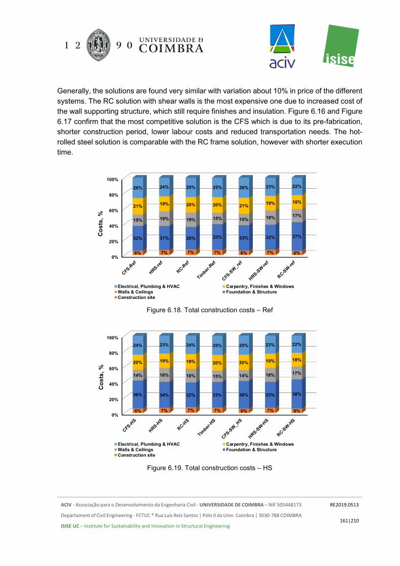
ACIV - Associação para o Desenvolvimento da Engenharia Civil - UNIVERSIDADE DE COIMBRA – NIF 505448173
Departament of Civil Engineering - FCTUC * Rua Luís Reis Santos | Pólo II da Univ. Coimbra | 3030-788 COIMBRA
ISISE UC – Institute for Sustainability and Innovation in Structural Engineering
RE2019.0513
161|210
Generally, the solutions are found very similar with variation about 10% in price of the different systems. The RC solution with shear walls is the most expensive one due to increased cost of the wall supporting structure, which still require finishes and insulation. Figure 6.16 and Figure 6.17 confirm that the most competitive solution is the CFS which is due to its pre-fabrication, shorter construction period, lower labour costs and reduced transportation needs. The hot-rolled steel solution is comparable with the RC frame solution, however with shorter execution time.
Figure 6.18. Total construction costs – Ref
Figure 6.19. Total construction costs – HS
0%
20%
40%
60%
80%
100%
6% 7% 7% 7% 6% 7% 6%
32% 31% 29% 33% 33% 32% 37%
15% 19% 19% 15% 15% 18% 17%
21% 19% 20% 20% 21% 19% 18%
26% 24% 25% 25% 26% 23% 22%
Cos
ts, %
Electrical, Plumbing & HVAC Carpentry, Finishes & WindowsWalls & Ceilings Foundation & StructureConstruction site
0%
20%
40%
60%
80%
100%
6% 7% 7% 7% 6% 7% 6%
36% 34% 32% 33% 36% 33% 38%
14% 18% 18% 15% 14% 18% 17%
20% 19% 19% 20% 20% 19% 18%
24% 23% 24% 25% 25% 23% 22%
Cos
ts, %
Electrical, Plumbing & HVAC Carpentry, Finishes & WindowsWalls & Ceilings Foundation & StructureConstruction site

ACIV - Associação para o Desenvolvimento da Engenharia Civil - UNIVERSIDADE DE COIMBRA – NIF 505448173
Departament of Civil Engineering - FCTUC * Rua Luís Reis Santos | Pólo II da Univ. Coimbra | 3030-788 COIMBRA
ISISE UC – Institute for Sustainability and Innovation in Structural Engineering
RE2019.0513
162|210
Figure 6.18 and Figure 6.19 show the percentage of the different parts in the total structural costs. Together the construction site and structure are responsible for 36% and 43% of the construction costs for the reinforced concrete frame and reinforced concrete shear wall solutions, respectively; 38% for the cold-formed steel solutions, 38% and 39% for the hot-rolled steel solution and 40% for the timber one.
The type of wall system leads to variation of the total costs of the walls and ceilings to vary between 15 and 19% of the construction cost.
6.6 FINAL REMARKS
From the conducted planning it was concluded that the reinforced concrete building is the one with the longer construction times followed by the timber building, hot-rolled steel building and finally the cold-formed steel building. On average (considering the reference and high seismic case) the construction period is reduced by about 89 days (22.2%) when the cold-formed steel framing solution is selected.
Modular construction systems are inherently faster solutions to build/erect. The construction schedule can be significantly reduced when a prefabricated, industrialized modular solution is selected for the structural framing. Reducing the overall number of activities on-site will enhance construction times. The workshop efficiency is higher as well as the accuracy and quality of the final product when compared with on-site fabrication. However, a prefabricated solution, as previously mentioned, requires proper planning ensuring that when needed all prefabricated elements can be delivered on time in the construction site avoiding delays. Hence, the construction schedule of prefabricated solutions can be highly dependent on the lead-in time required from the moment the elements are ordered to the moment they are delivered on-site. In this study, it was assumed that all elements will be delivered to the construction site in due time.
The reduced construction schedule led consequently to significant cost savings when the total construction cost was estimated, enhancing the competitiveness of the cold-formed steel solution in the construction sector. These savings are related with the manpower required, the overall material quantity, and as well with lower rental times for cranes and other types of equipment. It is worth noting that prefabricated solutions, both using steel or timber, will present high levels of precision and overall quality. This added dimension precision will also contribute to lower material waste in the construction site, reducing the overall impact of the construction site in the surrounding environment or area. For the reinforced concrete solutions, the use of the excess material, which also leads to higher transportation requirements, must be carefully planned in order to reduce its impact on the environment.
Another important aspect that must be taken into consideration is the adaptability, and the relocation of the building. Prefabricated modular cold-formed steel solutions are inherently

ACIV - Associação para o Desenvolvimento da Engenharia Civil - UNIVERSIDADE DE COIMBRA – NIF 505448173
Departament of Civil Engineering - FCTUC * Rua Luís Reis Santos | Pólo II da Univ. Coimbra | 3030-788 COIMBRA
ISISE UC – Institute for Sustainability and Innovation in Structural Engineering
RE2019.0513
163|210
highly adaptable solutions allowing the building to be easily modified to address new requirements that may arise during its lifetime. Moreover, if necessary, its modularity allows for future relocation of the building since this type of building is more easily disassembled. Specifically, for the studied cases, relocation will require the construction of new foundations and execution of new composite slabs. The remaining framing system can be reused and relocated. The hot-rolled steel and timber solutions also share this potential for adaptability and relocation. These characteristics may ensure that the lifetime of the structure can be extended if necessary.
Finally, it is worth mentioning that using prefabricated lightweight solutions with faster construction schedules may bring additional cost savings in different construction operations. For instance, the reduced number of on-site works will lead to lower waste and lower disposal costs, as well as to increased safety levels for the workers, whereas the reduced programme will for sure lead to reduced costs and usage of elevation equipment.
ACIV - Associação para o Desenvolvimento da Engenharia Civil - UNIVERSIDADE DE COIMBRA – NIF 505448173
Departament of Civil Engineering - FCTUC * Rua Luís Reis Santos | Pólo II da Univ. Coimbra | 3030-788 COIMBRA
ISISE UC – Institute for Sustainability and Innovation in Structural Engineering
RE2019.0513
164|210
7. CONCLUSIONS
A comparative study of different structural solutions for a four-storey residential building was performed. In this report, a light steel framing solution for multi-storey residential buildings was compared with other structural systems using different structural materials, including hot-rolled steel, reinforced concrete and timber. For each structural system, different seismicity scenarios were considered. Based on the same architectural layout 3D structural modelling and analysis have been performed using the software SAP2000 [3]. In this study, the bill of materials for each structural solution was determined, providing data related to the competitiveness of each material for the structural framing for residential buildings. The following conclusions can be drawn from the observations reported in this work:
(1) As expected, the heaviest structural solutions are the reinforced concrete ones, for all seismicity levels tested. The lightest building is the cold-formed steel one. The weight of the reinforced concrete building is 121% higher than the weight of the G550 cold-formed steel building, 71% higher than the hot-rolled steel building and 76% higher than the timber building (for the reference scenario – no seismic action);
(2) In terms of percentage weight increase, the lateral force resisting system prescribed for the cold-formed steel building is the one where the seismic action has a more significant impact. Increasing the seismicity level, the weight of the lateral force resisting system increases up to 155% when compared with the reference situation. The percentage weight increase was up to 63%, 33% and 29%, respectively for the hot-rolled steel, reinforced concrete and timber buildings (high seismicity level);
(3) The foundations for the cold-formed steel and timber buildings were the lightest, and the foundations for the reinforced concrete solution the heaviest, as expected. The reinforced concrete foundations are 74% heavier than the cold-formed steel ones for the high seismic case;
(4) The seismic location plays a significant role in the estimation of the overall weight of the substructure and superstructure of a building. The weight of the foundations increased up to 25% for the reinforced concrete solution when the high seismicity level was considered;
(5) Hot-rolled steel building does not require formwork or a significant amount of shoring but has extra costs with secondary structures for facades and internal walls. Also, the material may be more expensive. Steel solutions are faster to erect, with higher quality and narrower tolerances. Moreover, steel solutions are highly adaptable, reusable, expandable and recycled.
(6) The reinforced concrete building has additional costs with formwork, shoring, reinforcement processing (cutting and folding), a secondary structure for facades and internal walls. However, the reinforced concrete building is more durable and requires less maintenance.

ACIV - Associação para o Desenvolvimento da Engenharia Civil - UNIVERSIDADE DE COIMBRA – NIF 505448173
Departament of Civil Engineering - FCTUC * Rua Luís Reis Santos | Pólo II da Univ. Coimbra | 3030-788 COIMBRA
ISISE UC – Institute for Sustainability and Innovation in Structural Engineering
RE2019.0513
165|210
(7) The bigger the concrete consumption the bigger the waste (excess material). The excess material shall be properly handled, and proper planning is required to tackle this problem.
(8) In what concerns the acoustic behaviour of the analysed buildings, it can be said that, for all structural solutions, it is possible to define engineering solutions that allow the fulfilment of the regulations in most European countries. This is valid both for airborne and for impact sounds;
(9) Although, in general, heavier solutions (concrete or hot-rolled steel structures) tend to exhibit a better acoustic behaviour, they usually also require the introduction of improvements in order to reach the required performance levels. Indeed, the same type of improvement solutions can also be used for lighter constructive solutions (cold-formed steel or wood) with minor adaptations (for example, adjusting the thickness of resilient layer in floating floors).
(10) In what concerns the fire behaviour, as expected the solution with less fire protection material is the reinforced concrete one, followed by the hot-rolled steel, timber and finally the cold-formed steel (CFS) solution, hence the reinforced concrete solution is the best solution when the fire resistance criteria is being assessed;
(11) Light steel framing (CFS) buildings usually present a good fire resistance but at the expense of fire protection. For this case study two 12.5 mm layers of gypsum boards or calcium silicate boards (for fire resistance rate of 60 minutes) on all walls are required, since all of them have load bearing function and consequently the fire protection material need is higher. Alternatively, only one Glasroc F Firecase with 25 mm can be used, minimizing space, labour and execution times;
(12) Hot-rolled steel structural elements (columns and beams) are protected using one 12.5 mm layer of gypsum board, hence fulfilling the R60 requirement;
(13) Comparing to the light steel framing building, the timber building will just need one layer of gypsum boards (in some internal walls the EI60 criteria is not required) due to the protective charring layer created in the wood members when subjected to high temperatures, whereas for the hot-rolled steel building no gypsum boards are required for the ceilings and internal wall, except for the partitioning system in the facades, between apartments, between apartments and the elevator shafts and between apartments and horizontal and vertical escape routes.
(14) If tensile membrane action is taken into account in the composite slabs for the hot-rolled steel solution, a reduction about 20% in the intumescent paint can be achieved (when it is used as fire protection system to protect the hot-rolled steel beams).
(15) The cold-formed steel solution is the fastest to be erected, taking advantage of its overall lightness and possibility of prefabrication. On average (considering the reference and high seismic case) the construction period is reduced by about 90 days (22.8%) when the cold-formed steel framing solution is selected.

ACIV - Associação para o Desenvolvimento da Engenharia Civil - UNIVERSIDADE DE COIMBRA – NIF 505448173
Departament of Civil Engineering - FCTUC * Rua Luís Reis Santos | Pólo II da Univ. Coimbra | 3030-788 COIMBRA
ISISE UC – Institute for Sustainability and Innovation in Structural Engineering
RE2019.0513
166|210
(16) The most competitive solution in terms of the total cost estimation was the Cold-Formed Steel solution, however it is worth mentioning that the actual difference between all tested solution is about 10%;
(17) The high levels of pre-fabrication presented by the CFS solution contributed to the significantly lower number of trucks coming onsite.
Based on the detailed assessment in terms of the structural behaviour, fire and acoustic performance, construction schedule and total cost, it is possible to highlight the most relevant advantages and disadvantages of each one of the tested solutions from social, environmental and economic perspectives:
(1) Cold-formed steel Building: • CFS solutions use less raw material; • From the cost estimation the CFS solution was the most competitive one, with the
smallest total cost and with the shortest construction schedule. The same conclusion was drawn even when a reinforced concrete core was considered as the lateral force resisting system for the CFS solution;
• The high levels of prefabrication and industrialization are a clear advantage over the other solutions from a technological and economic point of view, ensuring the creation of more cost-effective products and contributing significantly for the shortest construction schedule. Modularity and prefabrication techniques enhance the development of more technologically advanced solutions with significant value creation;
• Reduced cost with labour means that the owner/investor gets a more valuable end product;
• Cold-formed steel solutions are future-proof, with high levels of adaptability and flexibility which will bring additional economic and environmental advantages;
• Reduced logistics and year around construction possibility, with lower construction costs in winter when comparing with RC structures. Dry construction reduces risk of moisture problems;
• CFS buildings provide safer working conditions; • Same levels of comfort, health, wellbeing and safety can be achieved by all solutions
however the CFS one presents economic advantages over the others; • Highly sustainable solution since in the great majority of cases all basic materials
used are 100% recyclable (steel, gypsum, mineral wool). Steel may be recycled continuously;
• Prefabrication and industrialization of the construction process leads to lower waste in the workshop and in the construction site. Moreover, CFS solutions cause minimum disruption around the construction site, making it one of the best solutions for buildings in urban areas;

ACIV - Associação para o Desenvolvimento da Engenharia Civil - UNIVERSIDADE DE COIMBRA – NIF 505448173
Departament of Civil Engineering - FCTUC * Rua Luís Reis Santos | Pólo II da Univ. Coimbra | 3030-788 COIMBRA
ISISE UC – Institute for Sustainability and Innovation in Structural Engineering
RE2019.0513
167|210
• Lower demands in terms of transportation to the construction site, which represent an economic advantage and also a contribution to reduce pollution;
• To ensure the required safety levels CFS solutions require the use of more passive fire protection. Due to very high section factors and high thermal conductivity of the material CFS solutions have higher needs in terms of passive fire protection, mainly to fulfil the load bearing criteria.
(2) Hot-rolled steel Building: • The HRS solution was the 4th best solution in terms of total costs, however
comparing directly with the Reinforced concrete and Timber solutions the construction time is shorter;
• The HRS shares the same advantages of CFS in terms of environmental performance, being 100% recyclable;
• HRS steel solution has a lower level of prefabrication and industrialization when compared with the CFS solutions, but still presents a higher level when comparing with Reinforced Concrete solutions;
• The quality of the products and the overall quality is high, since steel will not warp, slip, crack or creep;
• Due to lower section factor the passive fire protection needs for load bearing capacity are smaller than for the CFS solution.
(3) Reinforced concrete building (both solutions – frames and with shear walls): • The RC solutions were the 3rd and the most expensive solutions, respectively for the
framed building and for the shear wall building, however the construction schedules are significantly longer than the one obtained for the CFS solutions;
• RC solutions are characterized by high consumption of raw materials, approximately two times the weight of the CFS solution;
• Weather dependent type of construction; • Errors are more common in RC structures which may lead to more warranty claims
and unexpected repairs; • RC solutions present very good fire behaviour both in terms of load bearing capacity
(R) (for the framed solution), integrity (E) and insultation (I) (shear wall solution and slabs in both cases);
• RC solutions are the least environmentally friendly solutions since its recyclability is more limited when compared with steel solutions;
• RC solutions present good durability however this type of buildings is not future-proof since it is quite difficult to readapt and change the end-use of the building;
• RC concrete rental costs associated with cranes, scaffolding, formworks and props are higher;
• Shrinkage causes crack development in RC structures, and this solutions are more prone to suffer with moisture problems.

ACIV - Associação para o Desenvolvimento da Engenharia Civil - UNIVERSIDADE DE COIMBRA – NIF 505448173
Departament of Civil Engineering - FCTUC * Rua Luís Reis Santos | Pólo II da Univ. Coimbra | 3030-788 COIMBRA
ISISE UC – Institute for Sustainability and Innovation in Structural Engineering
RE2019.0513
168|210
(4) Timber building: • The Timber solution is the 2nd most competitive one in terms of the total cost
estimated; • Timber is aesthetically pleasing; • Timber solutions usually have good fire resistance; however timber is a highly
combustible material, contributing to the fire load of a building and fire spread. Moreover, some types of treated Timber may emit toxic chemicals;
• Timber is not dimensionally stable since it can shrink and swell and can be destroyed by termites, carpenter bees and ants, since it is an organic material;
• Moist conditions may significantly impact the durability of Timber solutions
ACIV - Associação para o Desenvolvimento da Engenharia Civil - UNIVERSIDADE DE COIMBRA – NIF 505448173
Departament of Civil Engineering - FCTUC * Rua Luís Reis Santos | Pólo II da Univ. Coimbra | 3030-788 COIMBRA
ISISE UC – Institute for Sustainability and Innovation in Structural Engineering
RE2019.0513
169|210
8. REFERENCES
[1] ISO 10140-1:2010 - Acoustics -- Laboratory measurement of sound insulation of building elements -- Part 1: Application rules for specific products
[2] ISO 10140-2:2010 - Acoustics -- Laboratory measurement of sound insulation of building elements -- Part 2: Measurement of airborne sound insulation
[3] ISO 10140-3:2010 - Acoustics -- Laboratory measurement of sound insulation of building elements -- Part 3: Measurement of impact sound insulation
[4] ISO 10140-4:2010 - Acoustics -- Laboratory measurement of sound insulation of building elements -- Part 4: Measurement procedures and requirements
[5] ISO 10140-5:2010 - Acoustics -- Laboratory measurement of sound insulation of building elements -- Part 5: Requirements for test facilities and equipment
[6] ISO 16283-1:2014 - Acoustics -- Field measurement of sound insulation in buildings and of building elements -- Part 1: Airborne sound insulation
[7] ISO 16283-2:2015 - Acoustics -- Field measurement of sound insulation in buildings and of building elements -- Part 2: Impact sound insulation
[8] ISO 717-1:2013 - Acoustics -- Rating of sound insulation in buildings and of building elements -- Part 1: Airborne sound insulation
[9] ISO 717-2:2013 - Acoustics -- Rating of sound insulation in buildings and of building elements -- Part 1: Impact sound insulation
[10] ISO 3382-2:2008 - Acoustics -- Measurement of room acoustic parameters -- Part 2: Reverberation time in ordinary rooms
[11] ISO 12354-1:2017 - Building acoustics -- Estimation of acoustic performance of buildings from the performance of elements -- Part 1: Airborne sound insulation between rooms
[12] ISO 12354-2:2017 - Building acoustics -- Estimation of acoustic performance of buildings from the performance of elements -- Part 2: Impact sound insulation between rooms
[13] Rasmussen, B., Machimbarrena, M. (editors), COST Action TU0901 – Building acoustics throughout Europe. Volume 1: Towards a common framework in building acoustics throughout Europe. DiScript Preimpresion, S. L., 2014.
[14] IBC (2009), International Building Code.
ACIV - Associação para o Desenvolvimento da Engenharia Civil - UNIVERSIDADE DE COIMBRA – NIF 505448173
Departament of Civil Engineering - FCTUC * Rua Luís Reis Santos | Pólo II da Univ. Coimbra | 3030-788 COIMBRA
ISISE UC – Institute for Sustainability and Innovation in Structural Engineering
RE2019.0513
170|210
[15] Peel, M. C., Finlayson, B. L., and McMahon, T. A.: Updated world map of the Köppen-Geiger climate classification, Hydrol. Earth Syst. Sci., 11, 1633-1644, https://doi.org/10.5194/hess-11-1633-2007, 2007.
[16] CSI, Computers & Structures, SAP2000, version v.20.0.0.
[17] CEN (2004), EN 1998-1, Eurocode 8: Design of structure for seismic resistance. CEN, Brussels.
[18] Regime jurídico de segurança contra Incêndios em Edifícios - Decreto-Lei n.º 220/2008, de 12 de Novembro (RJ-SCIE).
[19] Portaria nº 1532/2008 de 29 de Dezembro - Regulamento Técnico de Segurança Contra Incêndio em Edifícios. 2008.
[20] CEN (2004), EN 1991-1-2, Eurocode 1: Actions on structures – Part 1-2: General actions – Actions on structures exposed to fire. CEN, Brussels.
[21] CEN (2004), EN 1992-1-2, Eurocode 2: Design of concrete structures – Part 1-2: General rules – Structural fire design. CEN, Brussels.
[22] CEN (2005), EN 1993-1-2, Eurocode 3: Design of steel structures – Part 1-2: General rules – Structural fire design. CEN, Brussels.
[23] CEN (2005), EN 1994-1-2, Eurocode 4: Design of composite steel and concrete structures – Part 1-2: General rules – Structural fire design. CEN, Brussels.
[24] CEN (2004), EN 1995-1-2, Eurocode 5: Design of timber structures – Part 1-2: General – Structural fire design. CEN, Brussels.
[25] Santos, P., Simões da Silva, L., Ungureanu, (2012). Energy efficiency of light weight steel framed buildings, P129, ECCS, Brussels.
[26] CEN (2004), EN 1997-1, Eurocode 7: Geotechnical design – Part 1: General rules. CEN, Brussles.
[27] Landolfo, R., Mazzolani, F., Dubina, D., Simões da Silva, L., D’Aniello, M. (2017). Design of steel structures for buildings in seismic areas. ECCS Eurocode Design Manuals, ECCS and Wiley, Brussels.
[28] CEN (2002), EN 1991-1-1, Eurocode 1: Actions on structures – Part 1-1: General actions – Densities, self-weight, imposed loads for buildings. CEN, Brussles.
[29] CEN (2005), EN 1990, Eurocode 0: Basis of structural design. CEN, Brussels.

ACIV - Associação para o Desenvolvimento da Engenharia Civil - UNIVERSIDADE DE COIMBRA – NIF 505448173
Departament of Civil Engineering - FCTUC * Rua Luís Reis Santos | Pólo II da Univ. Coimbra | 3030-788 COIMBRA
ISISE UC – Institute for Sustainability and Innovation in Structural Engineering
RE2019.0513
171|210
[30] CEN (2004), EN 1992-1-1, Eurocode 2: Design of concrete structures – Part 1-1: General rules and rules for buildings. CEN, Brussels.
[31] CEN (2005), EN 1993-1-1, Eurocode 3: Design of steel structures – Part 1-1: General rules and rules for buildings. CEN, Brussels.
[32] CEN (2006), EN 1993-1-3, Eurocode 3: Design of steel structures – Part 1-3: General rules – Supplementary rules for cold-formed members and sheeting. CEN, Brussels.
[33] CEN (2005), EN 1994-1-1, Eurocode 4: Design of composite steel and concrete structures – Part 1-1: General rules and rules for buildings. CEN, Brussels.
[34] CEN (2008), EN 1995-1-1, Eurocode 5: Design of timber structures – Part 1-1: General – Common rules and rules for buildings. CEN, Brussels.
[35] CEN (2004), EN 1998-5, Eurocode 8: Design of structures for earthquake resistance – Part 5: Foundations, retaining structures and geotechnical aspects. CEN, Brussels.

ACIV - Associação para o Desenvolvimento da Engenharia Civil - UNIVERSIDADE DE COIMBRA – NIF 505448173
Departament of Civil Engineering - FCTUC * Rua Luís Reis Santos | Pólo II da Univ. Coimbra | 3030-788 COIMBRA
ISISE UC – Institute for Sustainability and Innovation in Structural Engineering
RE2019.0513
172|210
ANNEX A. FACADES AND INTERNAL PARTITIONS A1. FACADE SYSTEM
As previously mentioned, for the external wall facade system three climatic areas were selected as well as two performance levels. The proposed solutions are suitable for residential use and can be adapted for different structural solutions. Table A.1 specifies and details the adopted facade systems.
Table A.1. Facade solutions adopted according to climatic areas and performance level.
Facade system Climatic areas
Csa-Csb Cfb Dfa-Dfb
Standard performance
External wall with Direct Render System
External wall with ETICS system
Double external wall with Direct Render System
High performance External wall with
ETICS system
Double external wall with Direct Render
System
External wall with Cladding system
The wall facade systems are based on the high performance Glasroc X sheathing board specifically designed for external use. The Glasroc X is ideal for external use, with high impact resistance, high fire resistance (up to 120 minutes), Euroclass A1 non-combustible reaction to fire performance and great resistance to mould growth and water penetration.
In Figure A.1 to Figure A.3, a schematic representation of the different external wall systems is depicted.
Figure A.1. Schematic representation of the Direct render (a)) and ETICS system (b)).

ACIV - Associação para o Desenvolvimento da Engenharia Civil - UNIVERSIDADE DE COIMBRA – NIF 505448173
Departament of Civil Engineering - FCTUC * Rua Luís Reis Santos | Pólo II da Univ. Coimbra | 3030-788 COIMBRA
ISISE UC – Institute for Sustainability and Innovation in Structural Engineering
RE2019.0513
173|210
Figure A.2. Schematic representation of the Double external wall with Direct Render System (a)) and the Double External wall with ETICS system (b)).
Figure A.3. Schematic representation of the External wall with Cladding system (Glasroc ® X).
A2. ELEVATORS AND STAIRS
To protect the elevator shaft introduced in the building the ShaftWall special partition system is prescribed for all different building typologies investigated. The ShaftWall system is a lightweight, fire resistant solution to protect elements in confined spaces. As for the external wall systems two performance levels were considered and consequently two product lines will be prescribed. The difference in performance is mainly related with the inherent fire resistance (EI – Integrity and Insulation criteria) and acoustic insulation. Two systems are prescribed, namely the PLACO® ShaftWall EI120 and PLACO® ShaftWall EI180.

ACIV - Associação para o Desenvolvimento da Engenharia Civil - UNIVERSIDADE DE COIMBRA – NIF 505448173
Departament of Civil Engineering - FCTUC * Rua Luís Reis Santos | Pólo II da Univ. Coimbra | 3030-788 COIMBRA
ISISE UC – Institute for Sustainability and Innovation in Structural Engineering
RE2019.0513
174|210
The ShaftWall system comprises a metal framing and two types of gypsum boards, namely the Coreboard ® (19 mm thickness) and a different number of PLACOFLAM ® boards, PPF BA 15 (15 mm thickness), depending on the desired performance level. The PLACOFLAM® is a board used mainly in constructive systems where high fire resistance requirements must be fulfilled. The Coreboard® gypsum board also presents good fire resistance performance, high thermal and acoustic inculation.
In Table A.2 the details of the adopted solutions are presented.
Table A.2. Definition of the most relevant properties of the ShaftWall partitioning system
Schematics Total thickness
Maximum height
Fire resistance
Acoustic insulation
Standard solution
105 mm 4.5 m EI 120 min 53 dB
High performance solution
120 mm 4.5 m EI 180 min 48 dB

ACIV - Associação para o Desenvolvimento da Engenharia Civil - UNIVERSIDADE DE COIMBRA – NIF 505448173
Departament of Civil Engineering - FCTUC * Rua Luís Reis Santos | Pólo II da Univ. Coimbra | 3030-788 COIMBRA
ISISE UC – Institute for Sustainability and Innovation in Structural Engineering
RE2019.0513
175|210
Table A.3. Definition of the most relevant properties of the Stairs partitioning system.
Schematics Weight Thickness Height Fire
Resistance Acoustic insulation
Standard solution
45 kg 98 mm 3.05 m EI 60 min 52 dB
High performance solution
47 kg 98 mm 3.05 m EI 60 min 53 dB
For the stairs the prescribed solutions are presented in Table A.3. The standard solution comprises two PPF 13 gypsum boards and two STD BA 13 gypsum boards. The high-performance solution uses a HABITO® gypsum board, replacing one of the STD BA 13. The HABITO® gypsum boards present enhanced mechanical behaviour with high load bearing capacity, effective acoustic insulation, high thermal insulation, fire reaction classification A2 s1 d0 and resistance to impacts. Both partitioning systems are able to guarantee a 60-minute fire resistance in terms of integrity (E) and insulation (I) criteria. The studs are spaced at 600 mm and PV ACUSTIVER 50 mineral wool is used.
A3. INTERNAL PARTITIONING
For the internal partitioning the architectural layout was carefully analysed and the most adequate solutions proposed. Dry areas, wet areas and compartmentation between different apartments and common areas were identified (see Figure 3.2). Hence, for partitioning according to the type of use of each compartment the solutions were selected. The types of partitioning identified were as follows:
• partitioning between different apartments and apartments to common areas;
• partitioning between dry areas within each one of the apartments;
• partitioning between dry and wet areas within each one of the apartments;
• partitioning between wet and wet areas within each one of the apartments;
• false ceiling for wet and dry areas.
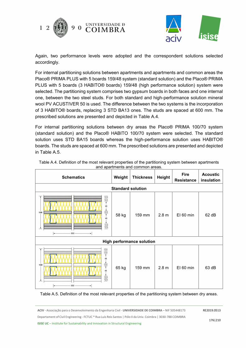
ACIV - Associação para o Desenvolvimento da Engenharia Civil - UNIVERSIDADE DE COIMBRA – NIF 505448173
Departament of Civil Engineering - FCTUC * Rua Luís Reis Santos | Pólo II da Univ. Coimbra | 3030-788 COIMBRA
ISISE UC – Institute for Sustainability and Innovation in Structural Engineering
RE2019.0513
176|210
Again, two performance levels were adopted and the correspondent solutions selected accordingly.
For internal partitioning solutions between apartments and apartments and common areas the Placo® PRIMA PLUS with 5 boards 159/48 system (standard solution) and the Placo® PRIMA PLUS with 5 boards (3 HABITO® boards) 159/48 (high performance solution) system were selected. The partitioning system comprises two gypsum boards in both faces and one internal one, between the two steel studs. For both standard and high-performance solution mineral wool PV ACUSTIVER 50 is used. The difference between the two systems is the incorporation of 3 HABITO® boards, replacing 3 STD BA13 ones. The studs are spaced at 600 mm. The prescribed solutions are presented and depicted in Table A.4.
For internal partitioning solutions between dry areas the Placo® PRIMA 100/70 system (standard solution) and the Placo® HABITO 100/70 system were selected. The standard solution uses STD BA15 boards whereas the high-performance solution uses HABITO® boards. The studs are spaced at 600 mm. The prescribed solutions are presented and depicted in Table A.5.
Table A.4. Definition of the most relevant properties of the partitioning system between apartments and apartments and common areas.
Schematics Weight Thickness Height Fire Resistance
Acoustic insulation
Standard solution
58 kg 159 mm 2.8 m EI 60 min 62 dB
High performance solution
65 kg 159 mm 2.8 m EI 60 min 63 dB
Table A.5. Definition of the most relevant properties of the partitioning system between dry areas.

ACIV - Associação para o Desenvolvimento da Engenharia Civil - UNIVERSIDADE DE COIMBRA – NIF 505448173
Departament of Civil Engineering - FCTUC * Rua Luís Reis Santos | Pólo II da Univ. Coimbra | 3030-788 COIMBRA
ISISE UC – Institute for Sustainability and Innovation in Structural Engineering
RE2019.0513
177|210
Schematics Weight Thickness Height Fire Resistance
Acoustic insulation
Standard solution
29 kg 100 mm 2.8 m EI 45 min 48 dB
High performance solution
33 kg 100 mm 2.8 m EI 60 min 48 dB
For internal partitioning solutions between dry and wet areas the Placo® HYDRO 100/70 system (standard solution) and the Placo® HYDRO with HABITO® gypsum board 100/70 system were selected. Tha standard solution Placo® HYDRO 100/70 comprises a PPM 15 and and STD BA 15 gypsum board. For the high-performance solution, the STD BA15 board is replaced by a HABITO® 15 one. The studs are spaced at 400 mm. For both standard and high-performance solution mineral wool PV ACUSTIVER 60 was used. The prescribed solutions are presented and depicted in Table A.6.
Table A.6. Definition of the most relevant properties of the partitioning system between dry and wet areas.
Schematics Weight Thickness Height Fire
Resistance Acoustic insulation
Standard solution
29 kg 100 mm 2.8 m __ 48 dB
High performance solution
31 kg 100 mm 2.8 m __ 48 dB

ACIV - Associação para o Desenvolvimento da Engenharia Civil - UNIVERSIDADE DE COIMBRA – NIF 505448173
Departament of Civil Engineering - FCTUC * Rua Luís Reis Santos | Pólo II da Univ. Coimbra | 3030-788 COIMBRA
ISISE UC – Institute for Sustainability and Innovation in Structural Engineering
RE2019.0513
178|210
For internal partitioning solutions between wet areas the Placo® HYDRO 100/70 system (standard solution) and the Placo® HYDRO with HABITO® gypsum board 100/70 system were selected. Tha standard solution comprises two PPM 15 gypsum boards, whereas the high performance one comprises two GLASROC® X 13 gypsum boards. The studs are spaced at 400 mm. For both standard and high-performance solution mineral wool PV ACUSTIVER 60 was used. The prescribed solutions are presented and depicted inTable A.7.
Table A.7. Definition of the most relevant properties of the partitioning system between wet areas.
Schematics Weight Thickness Height Fire Resistance
Acoustic insulation
Standard solution
30 kg 100 mm 2.8 m __ 48 dB
High performance solution
27 kg 95 mm 2.8 m __ 48 dB
For the false ceilings the proposed solutions will be used either in dry or wet areas. For both dry and wet areas the Placo® PRIMA F-530 system was selected, however the gypsum board is different. For the dry areas a STD BA 13 4PRO gypsum board was used whereas for wet areas a PPM gypsum board was selected. The prescribed solutions are presented and depicted in Table A.8.

ACIV - Associação para o Desenvolvimento da Engenharia Civil - UNIVERSIDADE DE COIMBRA – NIF 505448173
Departament of Civil Engineering - FCTUC * Rua Luís Reis Santos | Pólo II da Univ. Coimbra | 3030-788 COIMBRA
ISISE UC – Institute for Sustainability and Innovation in Structural Engineering
RE2019.0513
179|210
Table A.8. Definition of the most relevant properties of the false ceiling systems for both dry and wet areas.
Schematics Thickness Fire
Resistance Acoustic
Abs.
Dry areas
41 mm EI 15 min 0.1
Wet areas
41 mm __ 0.1
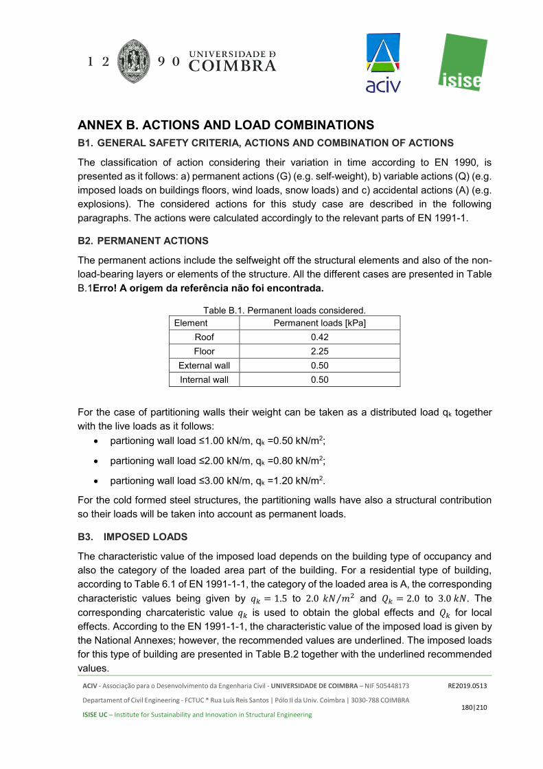
ACIV - Associação para o Desenvolvimento da Engenharia Civil - UNIVERSIDADE DE COIMBRA – NIF 505448173
Departament of Civil Engineering - FCTUC * Rua Luís Reis Santos | Pólo II da Univ. Coimbra | 3030-788 COIMBRA
ISISE UC – Institute for Sustainability and Innovation in Structural Engineering
RE2019.0513
180|210
ANNEX B. ACTIONS AND LOAD COMBINATIONS B1. GENERAL SAFETY CRITERIA, ACTIONS AND COMBINATION OF ACTIONS
The classification of action considering their variation in time according to EN 1990, is presented as it follows: a) permanent actions (G) (e.g. self-weight), b) variable actions (Q) (e.g. imposed loads on buildings floors, wind loads, snow loads) and c) accidental actions (A) (e.g. explosions). The considered actions for this study case are described in the following paragraphs. The actions were calculated accordingly to the relevant parts of EN 1991-1.
B2. PERMANENT ACTIONS
The permanent actions include the selfweight off the structural elements and also of the non-load-bearing layers or elements of the structure. All the different cases are presented in Table B.1Erro! A origem da referência não foi encontrada.
Table B.1. Permanent loads considered. Element Permanent loads [kPa]
Roof 0.42 Floor 2.25
External wall 0.50 Internal wall 0.50
For the case of partitioning walls their weight can be taken as a distributed load qk together with the live loads as it follows:
• partioning wall load ≤1.00 kN/m, qk =0.50 kN/m2;
• partioning wall load ≤2.00 kN/m, qk =0.80 kN/m2;
• partioning wall load ≤3.00 kN/m, qk =1.20 kN/m2.
For the cold formed steel structures, the partitioning walls have also a structural contribution so their loads will be taken into account as permanent loads.
B3. IMPOSED LOADS
The characteristic value of the imposed load depends on the building type of occupancy and also the category of the loaded area part of the building. For a residential type of building, according to Table 6.1 of EN 1991-1-1, the category of the loaded area is A, the corresponding characteristic values being given by 𝑞𝑘 = 1.5 to 2.0 𝑘𝑁 𝑚2⁄ and 𝑄𝑘 = 2.0 to 3.0 𝑘𝑁. The corresponding charcateristic value 𝑞𝑘 is used to obtain the global effects and 𝑄𝑘 for local effects. According to the EN 1991-1-1, the characteristic value of the imposed load is given by the National Annexes; however, the recommended values are underlined. The imposed loads for this type of building are presented in Table B.2 together with the underlined recommended values.
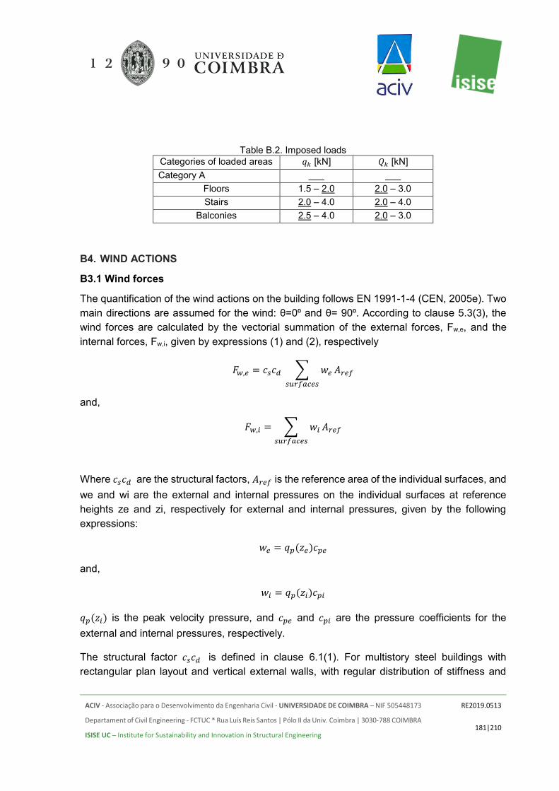
ACIV - Associação para o Desenvolvimento da Engenharia Civil - UNIVERSIDADE DE COIMBRA – NIF 505448173
Departament of Civil Engineering - FCTUC * Rua Luís Reis Santos | Pólo II da Univ. Coimbra | 3030-788 COIMBRA
ISISE UC – Institute for Sustainability and Innovation in Structural Engineering
RE2019.0513
181|210
Table B.2. Imposed loads Categories of loaded areas 𝑞𝑘 [kN] 𝑄𝑘 [kN] Category A ___ ___
Floors 1.5 – 2.0 2.0 – 3.0 Stairs 2.0 – 4.0 2.0 – 4.0
Balconies 2.5 – 4.0 2.0 – 3.0
B4. WIND ACTIONS
B3.1 Wind forces
The quantification of the wind actions on the building follows EN 1991-1-4 (CEN, 2005e). Two main directions are assumed for the wind: θ=0⁰ and θ= 90⁰. According to clause 5.3(3), the wind forces are calculated by the vectorial summation of the external forces, Fw,e, and the internal forces, Fw,i, given by expressions (1) and (2), respectively
𝐹𝑤,𝑒 = 𝑐𝑠𝑐𝑑 ∑ 𝑤𝑒
𝑠𝑢𝑟𝑓𝑎𝑐𝑒𝑠
𝐴𝑟𝑒𝑓
and,
𝐹𝑤,𝑖 = ∑ 𝑤𝑖
𝑠𝑢𝑟𝑓𝑎𝑐𝑒𝑠
𝐴𝑟𝑒𝑓
Where 𝑐𝑠𝑐𝑑 are the structural factors, 𝐴𝑟𝑒𝑓 is the reference area of the individual surfaces, and we and wi are the external and internal pressures on the individual surfaces at reference heights ze and zi, respectively for external and internal pressures, given by the following expressions:
𝑤𝑒 = 𝑞𝑝(𝑧𝑒)𝑐𝑝𝑒
and,
𝑤𝑖 = 𝑞𝑝(𝑧𝑖)𝑐𝑝𝑖
𝑞𝑝(𝑧𝑖) is the peak velocity pressure, and 𝑐𝑝𝑒 and 𝑐𝑝𝑖 are the pressure coefficients for the external and internal pressures, respectively.
The structural factor 𝑐𝑠𝑐𝑑 is defined in clause 6.1(1). For multistory steel buildings with rectangular plan layout and vertical external walls, with regular distribution of stiffness and

ACIV - Associação para o Desenvolvimento da Engenharia Civil - UNIVERSIDADE DE COIMBRA – NIF 505448173
Departament of Civil Engineering - FCTUC * Rua Luís Reis Santos | Pólo II da Univ. Coimbra | 3030-788 COIMBRA
ISISE UC – Institute for Sustainability and Innovation in Structural Engineering
RE2019.0513
182|210
mass, the structural factor 𝑐𝑠𝑐𝑑 , may be taken from Annex D of EN1991-1-4. For h = 12.8 m and b = 19,99 m (θ=0⁰), 𝑐𝑠𝑐𝑑 = 1 for h<15 m, and for b = 17.75 m (θ= 90⁰.), 𝑐𝑠𝑐𝑑 = 1.
B3.2 Reference height
The reference heights, ze, for vertical windward walls of rectangular plan buildings depend on the aspect ratio h/b and are always the upper heights of the different parts of the walls (clause 7.2.2(1)). For θ=0⁰ or 90⁰ (see Figure A.1), h=12.80m ≤ b = 19.99 m respectively h=12.80m ≤ b = 19.99 m therefore the height of the building will be considered in only one part. The resulting shape of the velocity pressure profile is shown in Figure B.1.
Figure B.1. Velocity pressure distribution on face D (𝜃 = 0º, 𝜃 = 90º).
B3.3 Calculation of external and internal pressure coefficients
External and internal pressure coefficients are determined according to clause 7.2 of EN 1991-1-4. Internal and external pressures shall be considered to act at the same time (clause 7.2.9). The worst combination of external and internal pressures shall be considered. According to clause 7.2.2(2), the façades are divided in different pressure zones, defined as a function of e, where e is the lesser of b or 2h.
For wind direction θ=0⁰ (see Figure B.2):
e = min(19.99; 25.60) = 19.99 m > d = 17.75 m
and for wind direction θ=90⁰ (see Figure B.3):
e = min(17.75; 25.6) = 17.75 m < d = 19.99 m

ACIV - Associação para o Desenvolvimento da Engenharia Civil - UNIVERSIDADE DE COIMBRA – NIF 505448173
Departament of Civil Engineering - FCTUC * Rua Luís Reis Santos | Pólo II da Univ. Coimbra | 3030-788 COIMBRA
ISISE UC – Institute for Sustainability and Innovation in Structural Engineering
RE2019.0513
183|210
Figure B.2. Pressure zones for wind direction θ=0⁰
Figure B.3. Pressure zones for wind direction θ=90⁰.
According to clause 7.2.2(3), the lack of correlation of wind pressures between the windward and leeward sides may be taken into account by multiplying the resulting force by a factor, f, that depends on the relation h/d for each case. Therefore, by linear interpolation between f = 1.0 for h/d ≥ 5 and f = 0.85 for h/d ≤ 1, the following factors are obtained: for θ=0⁰, f = 0.83 and for θ=0⁰, f = 0.83.
Table B.3. External pressure coefficients 𝑐𝑝𝑒
zone A B C D E
θ=0⁰ h/d=0.72 -1.2 -0.8 - 0.769 -0.438
θ=90⁰ h/d=0.64 -1.2 -0.8 -0.5 0.757 -0.414
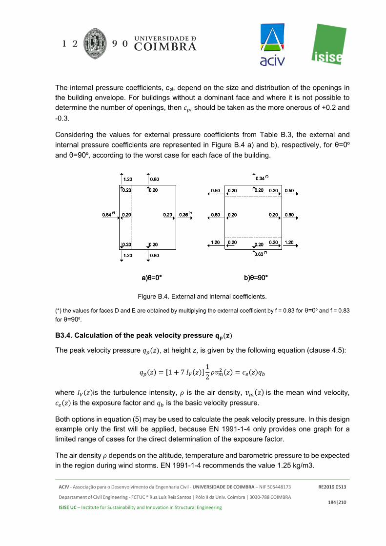
ACIV - Associação para o Desenvolvimento da Engenharia Civil - UNIVERSIDADE DE COIMBRA – NIF 505448173
Departament of Civil Engineering - FCTUC * Rua Luís Reis Santos | Pólo II da Univ. Coimbra | 3030-788 COIMBRA
ISISE UC – Institute for Sustainability and Innovation in Structural Engineering
RE2019.0513
184|210
The internal pressure coefficients, cpi, depend on the size and distribution of the openings in the building envelope. For buildings without a dominant face and where it is not possible to determine the number of openings, then 𝑐𝑝𝑖 should be taken as the more onerous of +0.2 and -0.3.
Considering the values for external pressure coefficients from Table B.3, the external and internal pressure coefficients are represented in Figure B.4 a) and b), respectively, for θ=0⁰
and θ=90⁰, according to the worst case for each face of the building.
Figure B.4. External and internal coefficients.
(*) the values for faces D and E are obtained by multiplying the external coefficient by f = 0.83 for θ=0⁰ and f = 0.83 for θ=90⁰.
B3.4. Calculation of the peak velocity pressure 𝐪𝐩(𝐳)
The peak velocity pressure 𝑞𝑝(𝑧), at height z, is given by the following equation (clause 4.5):
𝑞𝑝(𝑧) = [1 + 7 𝐼𝑉(𝑧)]1
2𝜌𝑣𝑚
2 (𝑧) = 𝑐𝑒(𝑧)𝑞𝑏
where 𝐼𝑉(𝑧)is the turbulence intensity, 𝜌 is the air density, 𝑣𝑚(𝑧) is the mean wind velocity, 𝑐𝑒(𝑧) is the exposure factor and 𝑞𝑏 is the basic velocity pressure.
Both options in equation (5) may be used to calculate the peak velocity pressure. In this design example only the first will be applied, because EN 1991-1-4 only provides one graph for a limited range of cases for the direct determination of the exposure factor.
The air density 𝜌 depends on the altitude, temperature and barometric pressure to be expected in the region during wind storms. EN 1991-1-4 recommends the value 1.25 kg/m3.

ACIV - Associação para o Desenvolvimento da Engenharia Civil - UNIVERSIDADE DE COIMBRA – NIF 505448173
Departament of Civil Engineering - FCTUC * Rua Luís Reis Santos | Pólo II da Univ. Coimbra | 3030-788 COIMBRA
ISISE UC – Institute for Sustainability and Innovation in Structural Engineering
RE2019.0513
185|210
B3.5. Calculation of mean wind velocity 𝒗𝒎(𝒛)
The mean wind velocity is given by (clause 4.3.1),
𝑣𝑚(𝑧) = 𝑐𝑟(𝑧)𝑐𝑜(𝑧)𝑣𝑏
where 𝑐𝑟(𝑧) is the roughness factor and 𝑐𝑜(𝑧) is the orography factor, taken as 1.0 unless otherwise specified in clause 4.3.3, and 𝑣𝑏 is the basic wind velocity. The roughness factor is specified in clause 4.3.2 and is given by:
𝑐𝑟(𝑧) = 𝑘𝑟𝑙𝑛 (𝑧
𝑧0)
⇐ 𝑧𝑚𝑖𝑛 ≤ 𝑧 ≤ 𝑧𝑚𝑎𝑥
𝑐𝑟(𝑧) = 𝑐𝑟(𝑧𝑚𝑖𝑛)
⇐ 𝑧 ≤ 𝑧𝑚𝑖𝑛
zmax may be taken as 200, 𝑧𝑚𝑖𝑛 is the minimum height, 𝑧0 is the roughness length, both defined in Table 4.1 of EN 1991-1-4 as a function of the terrain category, and 𝑘𝑟 is the terrain factor, depending on the roughness length 𝑧0 and given by:
𝑘𝑟 = 0.19 (𝑧0
𝑧0,𝐼𝐼)
0.07
where 𝑧0,𝐼𝐼 = 0.05 𝑚. The basic wind velocity 𝑣𝑏 is calculated from (clause 4.2):
𝑣𝑏 = 𝑐𝑑𝑖𝑟𝑐𝑠𝑒𝑎𝑠𝑜𝑛𝑣𝑏0
where 𝑐𝑑𝑖𝑟 and 𝑐𝑠𝑒𝑎𝑠𝑜𝑛 are directional and seasonal factors, respectively, which may be given by the National Annexes. The recommended value, for each case, is 1.0. The fundamental value of the basic wind velocity, 𝑣𝑏,0, is also given in the National Annexes as a function of the regional wind maps.
Assuming 𝑣𝑏,0= 30 m/s, then 𝑣𝑏 = 𝑣𝑏,0= 30 m/s.
Assuming a terrain of category II (i.e., area with low vegetation and isolated obstacles), from Table 4.1 of EN1991-1-4, 𝑧0 = 𝑧0,𝐼𝐼 = 0.05 and 𝑧𝑚𝑖𝑛 = 2 𝑚, thus 𝑘𝑟 = 0.19. From equations (7), with 𝑧𝑚𝑖𝑛 < 𝑧 = 12.80 𝑚 < 𝑧𝑚𝑎𝑥:
𝑐𝑟(12.80) = 0.19𝑙𝑛 (12.80
0.05) = 1.054
and from equation (6),
𝑣𝑚(𝑧 = 12.80) = 1.054 𝑥 1.00 𝑥 1.00 𝑥 30 = 31.62 𝑚/𝑠

ACIV - Associação para o Desenvolvimento da Engenharia Civil - UNIVERSIDADE DE COIMBRA – NIF 505448173
Departament of Civil Engineering - FCTUC * Rua Luís Reis Santos | Pólo II da Univ. Coimbra | 3030-788 COIMBRA
ISISE UC – Institute for Sustainability and Innovation in Structural Engineering
RE2019.0513
186|210
B3.6. Calculation of the turbulence intensity 𝑰𝒗
The turbulence intensity is given by (clause 4.4(1)):
𝐼𝑣 =𝑘𝐼
𝑐0(𝑧)𝑙𝑛 (𝑧𝑧0
) ⇒ 𝑧𝑚𝑖𝑛 ≤ 𝑧 ≤ 𝑧𝑚𝑎𝑥
𝐼𝑣 = 𝐼𝑣(𝑧𝑚𝑖𝑛)
⇒ 𝑧 < 𝑧𝑚𝑖𝑛
where 𝑘𝐼 is the turbulence factor. The recommended value for 𝑘𝐼 = 1.0, thus for 𝑧𝑚𝑖𝑛 < 𝑧 =
12.8 < 𝑧𝑚𝑎𝑥:
𝐼𝑣 =1
1 × 𝑙𝑛 (12.80.05
)= 0.18
Finally, from equation (5), for 𝑧 = 12.80 𝑚:
𝑞𝑝(𝑧 = 12.80 𝑚) = [1 + 7 × 0.15]1
2× 1.25 × 31.622 = 1281.02 𝑁 𝑚2 = 1.28 𝑘𝑁 𝑚2⁄⁄
B3.7. Calculation of external and internal pressures
The external and internal pressures are obtained from equations (3) and (4) and are indicated in Table B.4. Note that external pressures are already multiplied by the structural factor, 𝑐𝑠𝑐𝑑, from equation (1). In Figure B.5 a) and b) the resulting values are represented for θ=0⁰ and θ=90⁰.
Table B.4. External and internal pressures.
𝑐𝑠𝑐𝑑 A B C D E
θ= 0⁰ cScdwe -1.536 -1.024 - 0.98432 -0.56064
wi 0.256 0.256 - 0.256 0.256
θ= 90⁰ cScdwe -1.536 -1.024 -0.64 0.96896 -0.52992
wi 0.256 0.256 0.256 0.256 0.256

ACIV - Associação para o Desenvolvimento da Engenharia Civil - UNIVERSIDADE DE COIMBRA – NIF 505448173
Departament of Civil Engineering - FCTUC * Rua Luís Reis Santos | Pólo II da Univ. Coimbra | 3030-788 COIMBRA
ISISE UC – Institute for Sustainability and Innovation in Structural Engineering
RE2019.0513
187|210
Figure B.5. Wind pressures (kN/m2) on walls, for a) θ=0⁰ and b) θ=90⁰.
B5. SEISMIC ACTIONS
B4.1. Introduction
The earthquake action was quantified following EN 1998-1 and a response spectrum response analysis was defined accordingly. The building is considered to be Class II of importance.
The design response spectrum is given by the following equations:
0 BT T ( )2 2.5 2
3 3e g
B
TS T a S
T q
= + −
B CT T T ( )2.5
e gS T a Sq
=
C DT T T ( )
2.5 Cg
e
g
Ta S
q TS T
a
=
DT T ( ) 2
2.5 C Dg
e
g
T Ta S
q TS T
a
=
The parameter β is the lower bound factor for the horizontal design spectrum, whose appropriate value should be provided by the National Annexes. EC8 recommends assuming β = 0,2.

ACIV - Associação para o Desenvolvimento da Engenharia Civil - UNIVERSIDADE DE COIMBRA – NIF 505448173
Departament of Civil Engineering - FCTUC * Rua Luís Reis Santos | Pólo II da Univ. Coimbra | 3030-788 COIMBRA
ISISE UC – Institute for Sustainability and Innovation in Structural Engineering
RE2019.0513
188|210
The values to be ascribed to TB, TC, TD and S for each ground type and type (shape) of spectrum (Type 1 or Type 2) to be used in a country may be found in its National Annex. Type 1 corresponds to moderate to large magnitude earthquakes, namely with with surface wave magnitude Ms larger than 5.5. Type 2 corresponds to low magnitude earthquakes with Ms less than 5.5. The recommended values for the spectral parameters are given in
Table B.5.
The behavior factor for steel structures according to EN 1998-1 design concepts is described in Figure B.6. The seismic base shear force formula is presented in (17).
𝐹𝑏 = 𝛾𝐼,𝑒𝑆𝑑(𝑇1)𝑚𝜆
Where: 𝛾𝐼,𝑒 is the importancy coefficient of the building, 𝑆𝑑(𝑇1) is the design response spectrum, 𝑚 is the mass of the structure and 𝜆 is a correction coefficient that takes into account the contributions of the fundamental modal mass.
Table B.5. EC8 recommended values of the parameters describing both Type 1 and Type 2 elastic response spectra
Elastic Response Spectra
Ground Type
S TB (s) TC (s) TD (s)
Type 1
A 1.0 0.15 0.4 2.0
B 1.2 0.15 0.5 2.0
C 1.15 0.20 0.6 2.0
D 1.35 0.20 0.8 2.0
E 1.4 0.15 0.5 2.0
Type 2
A 1.0 0.05 0.25 1.2
B 1.35 0.05 0.25 1.2
C 1.5 0.10 0.25 1.2
D 1.8 0.10 0.30 1.2
E 1.6 0.05 0.25 1.2

ACIV - Associação para o Desenvolvimento da Engenharia Civil - UNIVERSIDADE DE COIMBRA – NIF 505448173
Departament of Civil Engineering - FCTUC * Rua Luís Reis Santos | Pólo II da Univ. Coimbra | 3030-788 COIMBRA
ISISE UC – Institute for Sustainability and Innovation in Structural Engineering
RE2019.0513
189|210
Figure B.6. Design concepts according to EN 1998-1.
B4.2. Medium seismicity area
Faro, in Portugal, was chosen as the representative location for medium seismicity. The corresponding peak ground acceleration agR (m/s2) for Type 1 is 2.0 m/s2 while for Type 2 it equals 1.7 m/s2.
Figure A.9. Seismic zoning in Portugal
B4.3. High seismicity area
Bucharest, in Romania, was chosen as the representative location for high seismicity. In Romania, according to the National Annex of EN 1998-1, the type of ground classification

ACIV - Associação para o Desenvolvimento da Engenharia Civil - UNIVERSIDADE DE COIMBRA – NIF 505448173
Departament of Civil Engineering - FCTUC * Rua Luís Reis Santos | Pólo II da Univ. Coimbra | 3030-788 COIMBRA
ISISE UC – Institute for Sustainability and Innovation in Structural Engineering
RE2019.0513
190|210
(A.B,C,D,E, S1 and S2) from does not take place in the present. For design purposes, the type of ground it is being classified by the Tc spectrum period in three different zones as inFigure B.7. In Figure B.8 the design ground acceleration 𝑎𝑔 map is presented according to the National Annex P100/1-2013:
Figure B.7. Type of ground classification via the Tc spectrum period, National Annex P100/1-2013

ACIV - Associação para o Desenvolvimento da Engenharia Civil - UNIVERSIDADE DE COIMBRA – NIF 505448173
Departament of Civil Engineering - FCTUC * Rua Luís Reis Santos | Pólo II da Univ. Coimbra | 3030-788 COIMBRA
ISISE UC – Institute for Sustainability and Innovation in Structural Engineering
RE2019.0513
191|210
Figure B.8. The design ground acceleration 𝑎𝑔 for an event with MRI=225 years and an exceeding probability of 20%
The normalised elastic response spectrum β(t) for the absolute acceleration of horizontal ground movement are presented in (11-14) and Figure B.9, considering ξ=5% the critical damping and the corner periods TB, TC and TD. The values of the corner periods are displayed in Table B.6.
0 ≤ 𝑇 ≤ 𝑇𝐵 𝛽(𝑇) = 1 + (𝛽0 − 1)
𝑇𝐵 𝑇
𝑇𝐵 ≤ 𝑇 ≤ 𝑇𝐶 𝛽(𝑇) = 𝛽0
𝑇𝐶 ≤ 𝑇 ≤ 𝑇𝐷 𝛽(𝑇) = 𝛽0
𝑇𝐶
𝑇
𝑇𝐷 ≤ 𝑇 ≤ 5𝑠 𝛽(𝑇) = 𝛽0
𝑇𝐶𝑇𝐷
𝑇2
Table B.6. The corner periods TB, TC and TD
TC 0.70 s 1.00 s 1.60 s
TB 0.14 s 0.20 s 0.32 s

ACIV - Associação para o Desenvolvimento da Engenharia Civil - UNIVERSIDADE DE COIMBRA – NIF 505448173
Departament of Civil Engineering - FCTUC * Rua Luís Reis Santos | Pólo II da Univ. Coimbra | 3030-788 COIMBRA
ISISE UC – Institute for Sustainability and Innovation in Structural Engineering
RE2019.0513
192|210
TD 3.00 s 3.00 s 2.00 s
Figure B.9. Normalised elastic response spectrum 𝛽(𝑡) for corner periods TB, TC and TD
The design spectrum as described by P10/1-2013 is defined by a function of the horizontal ground acceleration 𝑎𝑔, the normalised elastic response spectrum 𝛽(𝑡) and the behavior factor q. The relations for the design spectrum are presented in (15-16) as it follows:
0 < 𝑇 ≤ 𝑇𝐵 𝑆𝑑(𝑇) = 𝑎𝑔 (1 +
𝛽0𝑞 − 1
𝑇𝐵𝑇)
𝑇 > 𝑇𝐵 𝑆𝑑(𝑇) = 𝑎𝑔
𝛽(𝑇)
𝑞≥ 0.20𝑎𝑔

ACIV - Associação para o Desenvolvimento da Engenharia Civil - UNIVERSIDADE DE COIMBRA – NIF 505448173
Departament of Civil Engineering - FCTUC * Rua Luís Reis Santos | Pólo II da Univ. Coimbra | 3030-788 COIMBRA
ISISE UC – Institute for Sustainability and Innovation in Structural Engineering
RE2019.0513
193|210
B6. LOAD COMBINATIONS
For the load combinations, the followed rules and methods are given in Annex A1 of EN 1990. According to clause A1.2.2. the following recommended values of the reduction factors ψ for the considered actions are the ones from Table B.7.
Table B.7. The reduction factors Ψ
Type of action Ψ0 Ψ1 Ψ2
Imposed loads in buildings: category A 0.7 0.5 0.3
Wind loads on buildings 0.7 0.2 0
The following combinations were taken into account for all types of buildings:
• Fundamental group of combinations where the predominant load can be the wind or live load:
𝐸𝑑 = 𝛾𝐺𝐺𝑘 + 𝛾𝑄,1𝑄𝑘,1 + 𝛾𝑄,𝑖𝜓0,𝑖𝑄𝑘,𝑖
The characteristic combination is described by (19):
1.35𝐷𝐿 + 1.5𝐿𝐿(𝑊𝐿) + 1.05𝑊𝐿 (𝐿𝐿)
Where: DL is the dead load, LL is the live load and WL is the wind load:
• Special group of combinations where the predominant load is earthquake
𝐸𝑑 = 𝐺𝑘 + 𝜓2,𝑖𝑄𝑘,𝑖 + 𝐴𝐸𝑑
1.00𝐷𝐿 + 0.3𝐿𝐿 + 1.00𝐸𝐿
Where: EL is the earthquake load.

ACIV - Associação para o Desenvolvimento da Engenharia Civil - UNIVERSIDADE DE COIMBRA – NIF 505448173
Departament of Civil Engineering - FCTUC * Rua Luís Reis Santos | Pólo II da Univ. Coimbra | 3030-788 COIMBRA
ISISE UC – Institute for Sustainability and Innovation in Structural Engineering
RE2019.0513
194|210
ANNEX C. LIGHT STEEL FRAMING C1. SUPERSTRUCTURE - REFERENCE CASE

ACIV - Associação para o Desenvolvimento da Engenharia Civil - UNIVERSIDADE DE COIMBRA – NIF 505448173
Departament of Civil Engineering - FCTUC * Rua Luís Reis Santos | Pólo II da Univ. Coimbra | 3030-788 COIMBRA
ISISE UC – Institute for Sustainability and Innovation in Structural Engineering
RE2019.0513
195|210
C2. SUPERSTRUCTURE - MEDIUM SEISMICITY LEVEL

ACIV - Associação para o Desenvolvimento da Engenharia Civil - UNIVERSIDADE DE COIMBRA – NIF 505448173
Departament of Civil Engineering - FCTUC * Rua Luís Reis Santos | Pólo II da Univ. Coimbra | 3030-788 COIMBRA
ISISE UC – Institute for Sustainability and Innovation in Structural Engineering
RE2019.0513
196|210
C3. SUPERSTRUCTURE - HIGH SEISMICITY LEVEL

ACIV - Associação para o Desenvolvimento da Engenharia Civil - UNIVERSIDADE DE COIMBRA – NIF 505448173
Departament of Civil Engineering - FCTUC * Rua Luís Reis Santos | Pólo II da Univ. Coimbra | 3030-788 COIMBRA
ISISE UC – Institute for Sustainability and Innovation in Structural Engineering
RE2019.0513
197|210
C4. FOUNDATIONS – REFERENCE

ACIV - Associação para o Desenvolvimento da Engenharia Civil - UNIVERSIDADE DE COIMBRA – NIF 505448173
Departament of Civil Engineering - FCTUC * Rua Luís Reis Santos | Pólo II da Univ. Coimbra | 3030-788 COIMBRA
ISISE UC – Institute for Sustainability and Innovation in Structural Engineering
RE2019.0513
198|210
ANNEX D. HOT-ROLLED STEEL SOLUTION D1. SUPERSTRUCTURE - REFERENCE
The hot-rolled steel solution consists of a moment-resisting structural system composed of hot-rolled steel sections. A detailed structural layout is presented. The structural solution consists of a composite floor system, supported on steel frames.
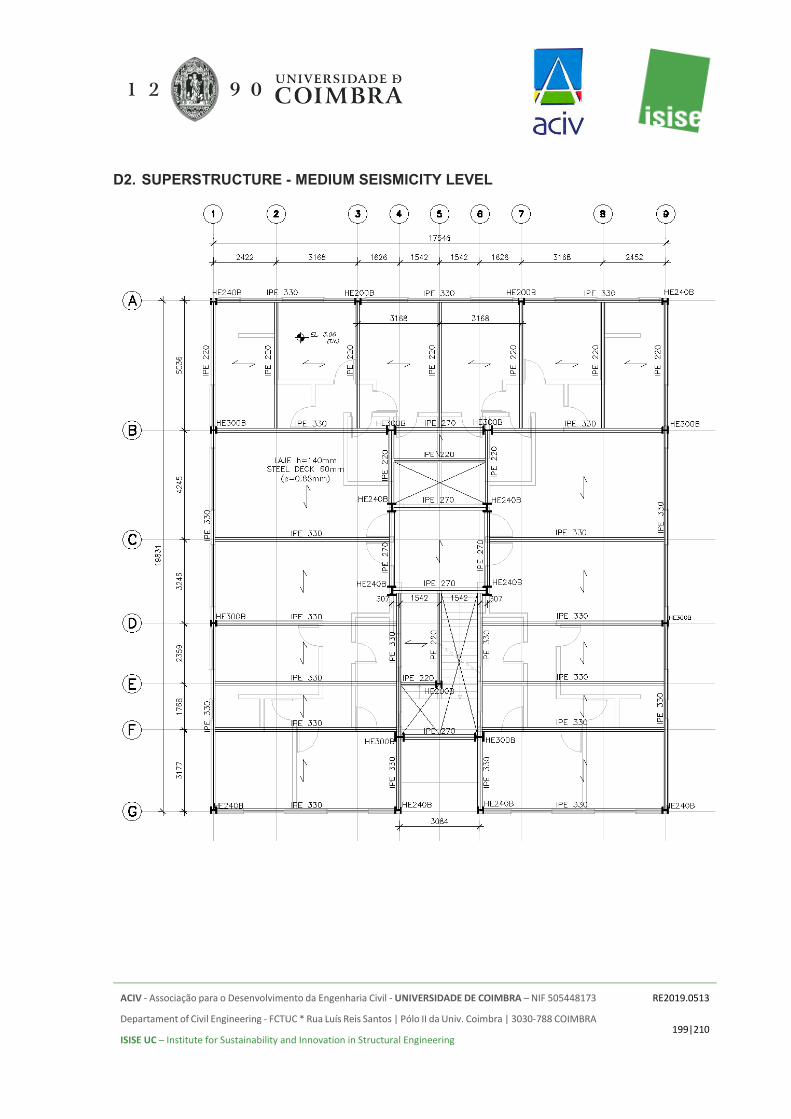
ACIV - Associação para o Desenvolvimento da Engenharia Civil - UNIVERSIDADE DE COIMBRA – NIF 505448173
Departament of Civil Engineering - FCTUC * Rua Luís Reis Santos | Pólo II da Univ. Coimbra | 3030-788 COIMBRA
ISISE UC – Institute for Sustainability and Innovation in Structural Engineering
RE2019.0513
199|210
D2. SUPERSTRUCTURE - MEDIUM SEISMICITY LEVEL

ACIV - Associação para o Desenvolvimento da Engenharia Civil - UNIVERSIDADE DE COIMBRA – NIF 505448173
Departament of Civil Engineering - FCTUC * Rua Luís Reis Santos | Pólo II da Univ. Coimbra | 3030-788 COIMBRA
ISISE UC – Institute for Sustainability and Innovation in Structural Engineering
RE2019.0513
200|210
D3. SUPERSTRUCTURE - HIGH SEISMICITY LEVEL
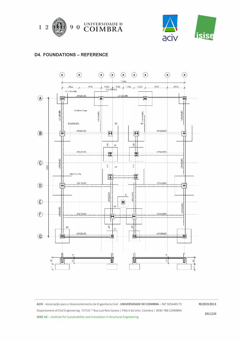
ACIV - Associação para o Desenvolvimento da Engenharia Civil - UNIVERSIDADE DE COIMBRA – NIF 505448173
Departament of Civil Engineering - FCTUC * Rua Luís Reis Santos | Pólo II da Univ. Coimbra | 3030-788 COIMBRA
ISISE UC – Institute for Sustainability and Innovation in Structural Engineering
RE2019.0513
201|210
D4. FOUNDATIONS – REFERENCE
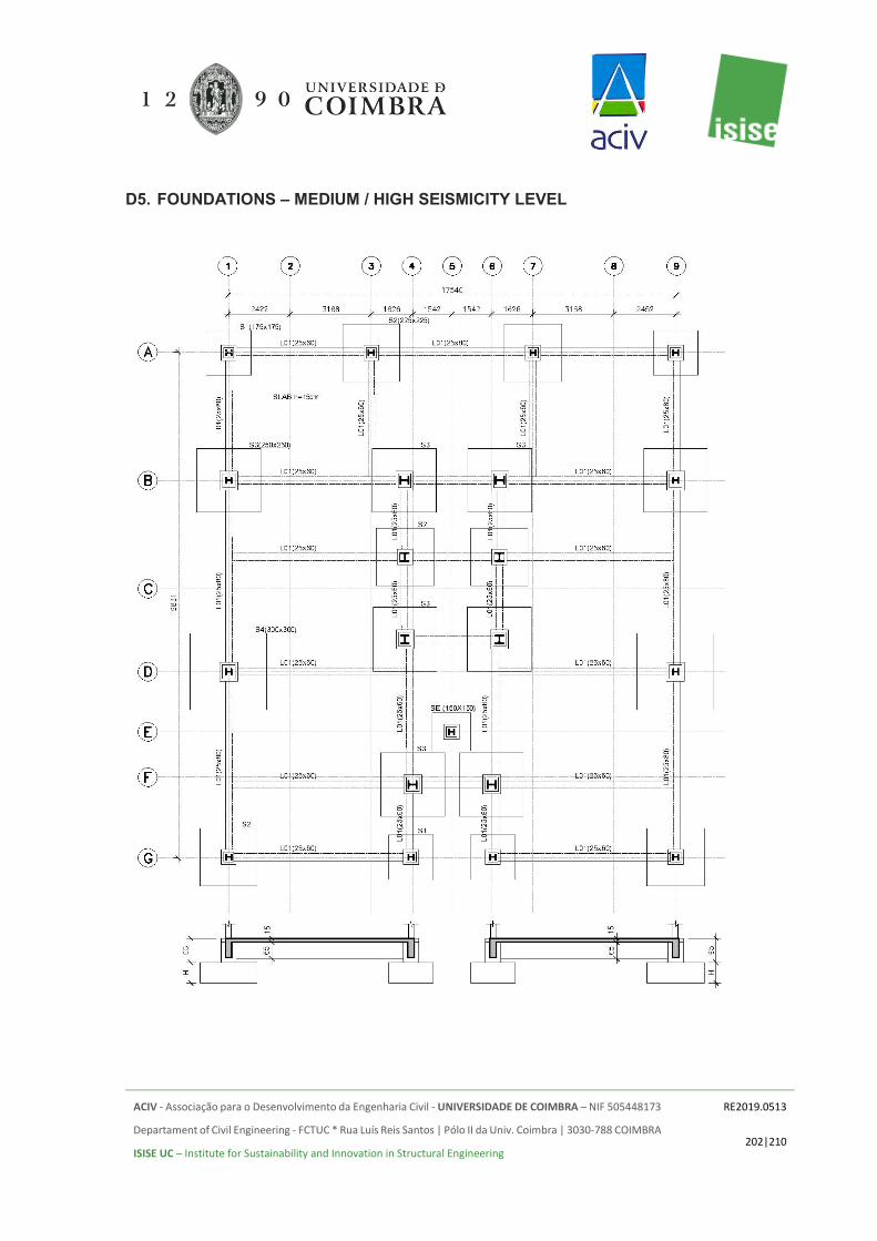
ACIV - Associação para o Desenvolvimento da Engenharia Civil - UNIVERSIDADE DE COIMBRA – NIF 505448173
Departament of Civil Engineering - FCTUC * Rua Luís Reis Santos | Pólo II da Univ. Coimbra | 3030-788 COIMBRA
ISISE UC – Institute for Sustainability and Innovation in Structural Engineering
RE2019.0513
202|210
D5. FOUNDATIONS – MEDIUM / HIGH SEISMICITY LEVEL

ACIV - Associação para o Desenvolvimento da Engenharia Civil - UNIVERSIDADE DE COIMBRA – NIF 505448173
Departament of Civil Engineering - FCTUC * Rua Luís Reis Santos | Pólo II da Univ. Coimbra | 3030-788 COIMBRA
ISISE UC – Institute for Sustainability and Innovation in Structural Engineering
RE2019.0513
203|210
ANNEX E. REINFORCED CONCRETE SOLUTION E1. SUPERSTRUCTURE - REFERENCE

ACIV - Associação para o Desenvolvimento da Engenharia Civil - UNIVERSIDADE DE COIMBRA – NIF 505448173
Departament of Civil Engineering - FCTUC * Rua Luís Reis Santos | Pólo II da Univ. Coimbra | 3030-788 COIMBRA
ISISE UC – Institute for Sustainability and Innovation in Structural Engineering
RE2019.0513
204|210
E2. SUPERSTRUCTURE - MEDIUM SEISMICITY LEVEL

ACIV - Associação para o Desenvolvimento da Engenharia Civil - UNIVERSIDADE DE COIMBRA – NIF 505448173
Departament of Civil Engineering - FCTUC * Rua Luís Reis Santos | Pólo II da Univ. Coimbra | 3030-788 COIMBRA
ISISE UC – Institute for Sustainability and Innovation in Structural Engineering
RE2019.0513
205|210
E3. SUPERSTRUCTURE - HIGH SEISMICITY LEVEL

ACIV - Associação para o Desenvolvimento da Engenharia Civil - UNIVERSIDADE DE COIMBRA – NIF 505448173
Departament of Civil Engineering - FCTUC * Rua Luís Reis Santos | Pólo II da Univ. Coimbra | 3030-788 COIMBRA
ISISE UC – Institute for Sustainability and Innovation in Structural Engineering
RE2019.0513
206|210
E4. FOUNDATIONS – REFERENCE

ACIV - Associação para o Desenvolvimento da Engenharia Civil - UNIVERSIDADE DE COIMBRA – NIF 505448173
Departament of Civil Engineering - FCTUC * Rua Luís Reis Santos | Pólo II da Univ. Coimbra | 3030-788 COIMBRA
ISISE UC – Institute for Sustainability and Innovation in Structural Engineering
RE2019.0513
207|210
E5. FOUNDATIONS – MEDIUM / HIGH SEISMICITY LEVELS

ACIV - Associação para o Desenvolvimento da Engenharia Civil - UNIVERSIDADE DE COIMBRA – NIF 505448173
Departament of Civil Engineering - FCTUC * Rua Luís Reis Santos | Pólo II da Univ. Coimbra | 3030-788 COIMBRA
ISISE UC – Institute for Sustainability and Innovation in Structural Engineering
RE2019.0513
208|210
ANNEX F. TIMBER SOLUTION F1. SUPERSTRUCTURE - REFERENCE
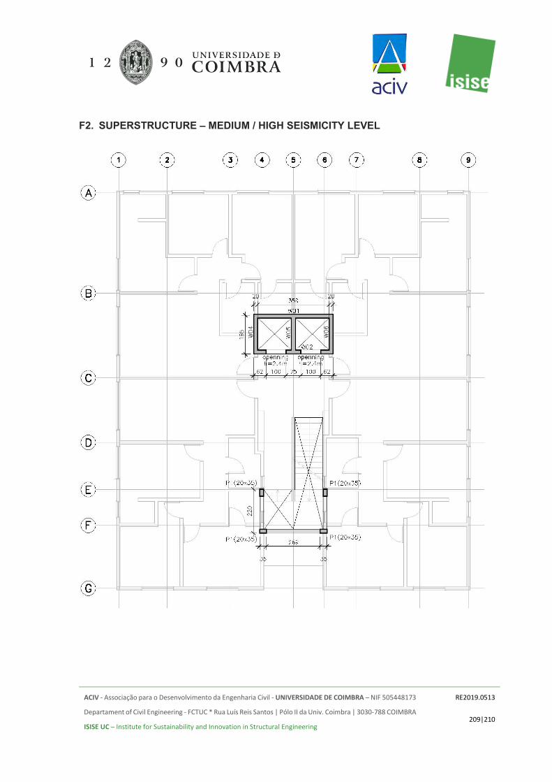
ACIV - Associação para o Desenvolvimento da Engenharia Civil - UNIVERSIDADE DE COIMBRA – NIF 505448173
Departament of Civil Engineering - FCTUC * Rua Luís Reis Santos | Pólo II da Univ. Coimbra | 3030-788 COIMBRA
ISISE UC – Institute for Sustainability and Innovation in Structural Engineering
RE2019.0513
209|210
F2. SUPERSTRUCTURE – MEDIUM / HIGH SEISMICITY LEVEL

ACIV - Associação para o Desenvolvimento da Engenharia Civil - UNIVERSIDADE DE COIMBRA – NIF 505448173
Departament of Civil Engineering - FCTUC * Rua Luís Reis Santos | Pólo II da Univ. Coimbra | 3030-788 COIMBRA
ISISE UC – Institute for Sustainability and Innovation in Structural Engineering
RE2019.0513
210|210
F3. FOUNDATIONS