Compact Switch Module CSM 1277 - Siemens AG Introduction 2 Network topologies 3 Product...
36
1 Introduction 2 Network topologies 3 Product characteristics SIMATIC NET 4 Mounting S7-1200 Compact Switch Module CSM 1277 5 Approvals and markings 6 References Operating Instructions 7 Graphics V. 1.20 A2B00079397B
Transcript of Compact Switch Module CSM 1277 - Siemens AG Introduction 2 Network topologies 3 Product...

1 Introduction
2Network topologies
3Product characteristics
SIMATIC NET
4Mounting
S7-1200 Compact Switch Module CSM 1277
5Approvals and markings
6References
Operating Instructions
7Graphics
V. 1.20 A2B00079397B

Legal information Warning notice system
This manual contains notices you have to observe in order to ensure your personal safety, as well as to prevent damage to property. The notices referring to your personal safety are highlighted in the manual by a safety alert symbol, notices referring only to property damage have no safety alert symbol. These notices shown below are graded according to the degree of danger.
DANGER indicates that death or severe personal injury will result if proper precautions are not taken.
WARNING indicates that death or severe personal injury may result if proper precautions are not taken.
CAUTION with a safety alert symbol, indicates that minor personal injury can result if proper precautions are not taken.
CAUTION without a safety alert symbol, indicates that property damage can result if proper precautions are not taken.
NOTICE indicates that an unintended result or situation can occur if the corresponding information is not taken into account.
If more than one degree of danger is present, the warning notice representing the highest degree of danger will be used. A notice warning of injury to persons with a safety alert symbol may also include a warning relating to property damage.
Qualified Personnel The product/system described in this documentation may be operated only by personnel qualified for the specific task in accordance with the relevant documentation for the specific task, in particular its warning notices and safety instructions. Qualified personnel are those who, based on their training and experience, are capable of identifying risks and avoiding potential hazards when working with these products/systems.
Proper use of Siemens products Note the following:
WARNING Siemens products may only be used for the applications described in the catalog and in the relevant technical documentation. If products and components from other manufacturers are used, these must be recommended or approved by Siemens. Proper transport, storage, installation, assembly, commissioning, operation and maintenance are required to ensure that the products operate safely and without any problems. The permissible ambient conditions must be adhered to. The information in the relevant documentation must be observed.
Trademarks All names identified by ® are registered trademarks of the Siemens AG. The remaining trademarks in this publication may be trademarks whose use by third parties for their own purposes could violate the rights of the owner.
Disclaimer of Liability We have reviewed the contents of this publication to ensure consistency with the hardware and software described. Since variance cannot be precluded entirely, we cannot guarantee full consistency. However, the information in this publication is reviewed regularly and any necessary corrections are included in subsequent editions.
Siemens AG order number: A2B00079397B Copyright © Siemens AG 2009, 2010. Industry Sector Ⓟ 08/2010 Technical data subject to change Postfach 48 48 90026 NÜRNBERG GERMANY

Compact Switch Module CSM 1277 Operating Instructions, V. 1.20, A2B00079397B 3
Table of contents
1 Introduction................................................................................................................................................ 5
1.1 Preface...........................................................................................................................................5 1.2 Introduction ....................................................................................................................................7
2 Network topologies .................................................................................................................................... 9 2.1 Network topologies ........................................................................................................................9
3 Product characteristics ............................................................................................................................ 11 3.1 Components of the product..........................................................................................................11 3.2 Unpacking and checking..............................................................................................................11 3.3 CSM 1277 product characteristics...............................................................................................12 3.4 TP ports........................................................................................................................................13 3.5 Displays........................................................................................................................................15 3.6 Technical specifications ...............................................................................................................16
4 Mounting.................................................................................................................................................. 19 4.1 Installation....................................................................................................................................19 4.2 Fixing onto standard mounting rails.............................................................................................20 4.3 Power supply................................................................................................................................22 4.4 Grounding ....................................................................................................................................23 4.5 Twisted pair cable ........................................................................................................................23 4.6 Fitting the IE FC RJ-45 Plug 180 .................................................................................................24 4.7 Possible sources of problems and how to deal with them...........................................................25
5 Approvals and markings .......................................................................................................................... 27 5.1 Notes on the CE Mark..................................................................................................................27
6 References .............................................................................................................................................. 29 6.1 References...................................................................................................................................29 6.2 Internet .........................................................................................................................................29
7 Graphics .................................................................................................................................................. 31 7.1 Dimension drawings.....................................................................................................................31
Glossary .................................................................................................................................................. 33 Index........................................................................................................................................................ 35

Table of contents
Compact Switch Module CSM 1277 4 Operating Instructions, V. 1.20, A2B00079397B

Compact Switch Module CSM 1277 Operating Instructions, V. 1.20, A2B00079397B 5
Introduction 11.1 Preface
Overview This section provides you with an overview of the functions of the unmanaged compact switch module CSM 1277.
Purpose of the Commissioning Manual This commissioning manual supports you when commissioning networks with the compact switch module CSM 1277.
Validity of this Commissioning Manual This commissioning manual is valid for the following device: CSM 1277 6GK7277-1AA10-0AA0
Further documentation The "SIMATIC NET Industrial Ethernet Twisted Pair and Fiber Optic Networks" manual contains additional information on other SIMATIC NET products that you can operate along with the CSM 1277 switch in an Industrial Ethernet network.
Finding information To help you to find the information you require more quickly, the manual includes not only the table of contents but also the following sections in the Appendix: ● Index ● Glossary
Audience This commissioning manual is intended for personnel involved in the commissioning of networks with the CSM 1277 compact switch module.

Introduction 1.1 Preface
Compact Switch Module CSM 1277 6 Operating Instructions, V. 1.20, A2B00079397B
Standards and approvals The CSM 1277 compact switch module meets the requirements for the CE, UL, C-Tick, FM and ATEX marks. You will find detailed information in the section "Approvals and Markings" in this commissioning manual in the "Approvals" table.
Note The specified approvals apply only when the corresponding mark is printed on the product.

Introduction 1.2 Introduction
Compact Switch Module CSM 1277 Operating Instructions, V. 1.20, A2B00079397B 7
1.2 Introduction
What is possible? The CSM 1277 device allows the cost-effective installation of Industrial Ethernet bus or star structures with switching functionality.
Note It is not possible to use the CSM 1277 switch in a redundant ring because it does not support redundancy.
Note If the CSM 1277 switch is supplied over long 24 V power supply lines or networks, measures are necessary to prevent interference by strong electromagnetic pulses on the supply lines. These can result, for example, due to lightning or switching of large inductive loads. One of the tests used to attest the immunity of the switch to electromagnetic interference was the "surge immunity test" according to EN61000-4-5. This test requires overvoltage protection for the power supply lines. A suitable device is, for example, the Dehn Blitzductor VT AD 24 V type no. 918 402 or comparable protective element. Manufacturer: DEHN+SÖHNE GmbH+Co.KG Hans Dehn Str.1 Postfach 1640 D-92306 Neumarkt, Germany
WARNING When used under hazardous conditions (zone 2), the CSM 1277 switch must be installed in an enclosure. To comply with ATEX 95 (EN 60079-15), this enclosure must be at least IP54 in compliance with EN 60529. WARNING – EXPLOSION HAZARD: DO NOT DISCONNECT EQUIPMENT WHEN A FLAMMABLE OR COMBUSTIBLE ATMOSPHERE IS PRESENT.

Introduction 1.2 Introduction
Compact Switch Module CSM 1277 8 Operating Instructions, V. 1.20, A2B00079397B

Compact Switch Module CSM 1277 Operating Instructions, V. 1.20, A2B00079397B 9
Network topologies 22.1 Network topologies
Switching technology allows extensive networks to be set up with numerous nodes and simplifies network expansion.
Which topologies can be implemented? Linear (bus) and star topologies can be implemented with the compact switch module CSM 1277.
Note Make sure that the maximum permitted cable lengths for the relevant devices are not exceeded. You will find the permitted cable lengths in the technical specifications.
Bus topology
Figure 2-1 Bus topology with the CSM 1277

Network topologies 2.1 Network topologies
Compact Switch Module CSM 1277 10 Operating Instructions, V. 1.20, A2B00079397B
Star topology
Figure 2-2 Star topology. Example with the CSM 1277

Compact Switch Module CSM 1277 Operating Instructions, V. 1.20, A2B00079397B 11
3Product characteristics
3.1 Components of the product The CSM 1277 compact switch module ships with the following: ● 3-pin terminal block (power supply) ● Operating Instructions (on the CD) ● CD
3.2 Unpacking and checking
Unpacking, checking 1. Make sure that the package is complete. 2. Check all the parts for transport damage.
WARNING Do not use any parts that show evidence of damage!

Product characteristics 3.3 CSM 1277 product characteristics
Compact Switch Module CSM 1277 12 Operating Instructions, V. 1.20, A2B00079397B
3.3 CSM 1277 product characteristics
Possible attachments The CSM 1277 has four RJ-45 jacks for the connection of end devices or other network segments.
Figure 3-1 Compact Switch Module CSM 1277

Product characteristics 3.4 TP ports
Compact Switch Module CSM 1277 Operating Instructions, V. 1.20, A2B00079397B 13
3.4 TP ports
Connector pinout On the CSM 1277, the TP ports are implemented as RJ-45 sockets with MDI-X assignment (Medium Dependent Interface–Autocrossover) of a network component.
Figure 3-2 RJ-45 jacks
Figure 3-3 RJ-45 jack
Table 3- 1 Pin assignment of the RJ-45 jack
Pin number Assignment Pin 8 n. c. Pin 7 n. c. Pin 6 TD- Pin 5 n. c. Pin 4 n. c. Pin 3 TD+ Pin 2 RD- Pin 1 RD+

Product characteristics 3.4 TP ports
Compact Switch Module CSM 1277 14 Operating Instructions, V. 1.20, A2B00079397B
NOTICE TP cords or TP-XP cords with a maximum length of 10 m can be connected to the RJ-45 TP port. With the IE FC cables and IE FC RJ-45 plug 180, an overall cable length of up to 100 m is permitted between two devices depending on the cable type.
Autonegotiation Autonegotiation means the automatic detection of the functionality of the port at the opposite end. Using autonegotiation, network components or end devices can detect the functionality available at the port of a partner device allowing automatic configuration of different types of device. With autonegotiation, two components connected to an Ethernet segment can exchange parameters and set themselves to match the supported communication functionality.
Note Devices not supporting autonegotiation must be set to 100 Mbps/ half duplex or 10 Mbps half duplex.
Note The CSM 1277 is a plug-and-play device that does not require settings to be made for commissioning.
Auto polarity exchange If the pair of receiving cables are incorrectly connected (RD+ and RD- swapped over), the polarity is adapted automatically.
MDI /MDIX autocrossover function The advantage of the MDI /MDIX autocrossover function is that straight-through cables can be used throughout and crossover Ethernet cables are unnecessary. This prevents malfunctions resulting from mismatching send and receive wires. This makes installation much easier for the user.
Insulation between the ports There are two port groups: Group1: P1 and P2 Group2: P3 and P4 Between ports of different port groups, an insulation voltage of 1.5 kV is adhered to (corresponds to IEEE802.3 Section 33.4.1.1, Environment B). For example between P1 and P4.
Product characteristics 3.5 Displays
Compact Switch Module CSM 1277 Operating Instructions, V. 1.20, A2B00079397B 15
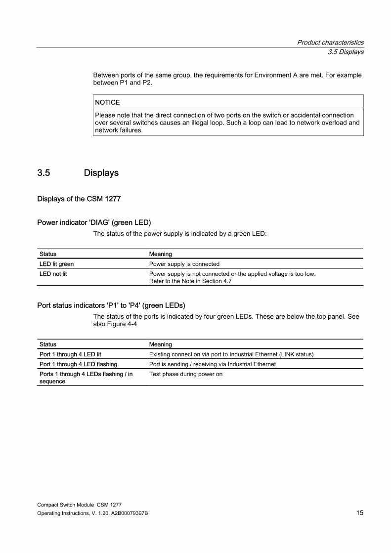
Between ports of the same group, the requirements for Environment A are met. For example between P1 and P2.
NOTICE Please note that the direct connection of two ports on the switch or accidental connection over several switches causes an illegal loop. Such a loop can lead to network overload and network failures.
3.5 Displays
Displays of the CSM 1277
Power indicator 'DIAG' (green LED) The status of the power supply is indicated by a green LED:
Status Meaning LED lit green Power supply is connected LED not lit Power supply is not connected or the applied voltage is too low.
Refer to the Note in Section 4.7
Port status indicators 'P1' to 'P4' (green LEDs) The status of the ports is indicated by four green LEDs. These are below the top panel. See also Figure 4-4
Status Meaning Port 1 through 4 LED lit Existing connection via port to Industrial Ethernet (LINK status) Port 1 through 4 LED flashing Port is sending / receiving via Industrial Ethernet Ports 1 through 4 LEDs flashing / in sequence
Test phase during power on
Product characteristics 3.6 Technical specifications
Compact Switch Module CSM 1277 16 Operating Instructions, V. 1.20, A2B00079397B
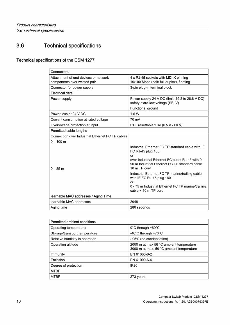
3.6 Technical specifications
Technical specifications of the CSM 1277 Connectors Attachment of end devices or network components over twisted pair
4 x RJ-45 sockets with MDI-X pinning 10/100 Mbps (half/ full duplex), floating
Connector for power supply 3-pin plug-in terminal block Electrical data Power supply Power supply 24 V DC (limit: 19.2 to 28.8 V DC)
safety extra-low voltage (SELV) Functional ground
Power loss at 24 V DC 1.6 W Current consumption at rated voltage 70 mA Overvoltage protection at input PTC resettable fuse (0.5 A / 60 V) Permitted cable lengths Connection over Industrial Ethernet FC TP cables0 – 100 m 0 – 85 m
Industrial Ethernet FC TP standard cable with IE FC RJ-45 plug 180 or over Industrial Ethernet FC outlet RJ-45 with 0 - 90 m Industrial Ethernet FC TP standard cable + 10 m TP cord Industrial Ethernet FC TP marine/trailing cable with IE FC RJ-45 plug 180 or 0 - 75 m Industrial Ethernet FC TP marine/trailing cable + 10 m TP cord
learnable MAC addresses / Aging Time learnable MAC addresses 2048 Aging time 280 seconds
Permitted ambient conditions Operating temperature 0°C through +60°C Storage/transport temperature -40°C through +70°C Relative humidity in operation ‹ 95% (no condensation) Operating altitude 2000 m at max 56 °C ambient temperature
3000 m at max. 50 °C ambient temperature Immunity EN 61000-6-2 Emission EN 61000-6-4 Degree of protection IP20 MTBF MTBF 273 years

Product characteristics 3.6 Technical specifications
Compact Switch Module CSM 1277 Operating Instructions, V. 1.20, A2B00079397B 17
Permitted ambient conditions Construction Dimensions (W x H x D) in mm 45 x 100 x 76 Weight in g 150 Installation options 35 mm DIN rail (DIN EN 60715 TH35)
Order numbers CSM 1277 6GK7277-1AA10-0AA0 "Industrial Ethernet TP and Fiber Optic Networks" manual
6GK1970-1BA10-0AA0
TP Cord RJ-45/RJ-45, 0.5 m 6XV1870-3QE50 TP Cord RJ-45/RJ-45, 1 m 6XV1870-3QH10 TP Cord RJ-45/RJ-45, 2 m 6XV1870-3QH20 TP Cord RJ-45/RJ-45, 6 m 6XV1870-3QH60 TP Cord RJ-45/RJ-45, 10 m 6XV1870-3QN10 IE FC Stripping Tool 6GK1901-1GA00 IE FC blade cassettes 6GK1901-1GB00 IE FC TP standard cable 6XV1840 2AH10 IE FC TP trailing cable 6XV1840-3AH10 IE FC TP marine cable 6XV1840-4AH10 IE FC RJ-45 Plug 180 pack of 1 6GK1 901-1BB10-2AA0 IE FC RJ-45 Plug 180 pack of 10 6GK1 901-1BB10-2AB0 IE FC RJ-45 Plug 180 pack of 50 6GK1 901-1BB10-2AE0
Note The number of connected switches influences the frame delay. When a frame passes through the CSM 1277, it is delayed by the store and forward function of the switch - with a 64 byte frame length by approx. 8 µs (at 100 Mbps) - with a 1500 byte frame length by approx. 125 µs (at 100 Mbps) This means that the more CSM 1277 switches that a frame passes through, the higher the frame delay will be.

Product characteristics 3.6 Technical specifications
Compact Switch Module CSM 1277 18 Operating Instructions, V. 1.20, A2B00079397B

Compact Switch Module CSM 1277 Operating Instructions, V. 1.20, A2B00079397B 19
4Mounting
4.1 Installation
Type of mounting The CSM 1277 compact switch module is intended for mounting on a 35 mm DIN rail. Wall mounting is possible (see S7-1200 System Manual).
Note When installing and operating the device, keep to the installation instructions and safety-related notices as described here and in the manual SIMATIC NET Industrial Ethernet Twisted Pair and Fiber Optic Networks /1/.
Note Provide suitable shade to protect the device against direct sunlight. This avoids unwanted warming of the device and prevents premature aging of the device and cabling.
WARNING If temperatures in excess of 70 °C occur on the cable or at the cable feed-in point, or the temperature at the branching point of the cables exceeds 80 °C, special measures need to be taken. If the equipment is operated at an ambient temperature of 50°C - 60°C, use cables with a permitted ambient temperature of at least 80°C.
WARNING Protective measures must be taken to avoid the rated voltage of the equipment being exceeded by more than 40% by transient overvoltages. This is the case if the equipment is supplied exclusively by SELV circuits.
WARNING If the CSM 1277 is operated in an ambient temperature of more than 55 °C, the temperature of the device housing may be higher than 70 °C. The subject unit must be located in a Restricted Access Location where access can only be gained by SERVICE PERSONNEL or by USERS who have been instructed about the reasons for the restrictions applied to the location and about any precautions that shall be taken when operated in an air ambient in excess of 55 °C.

Mounting 4.2 Fixing onto standard mounting rails
Compact Switch Module CSM 1277 20 Operating Instructions, V. 1.20, A2B00079397B
4.2 Fixing onto standard mounting rails
Installation on a 35 mm DIN rail
Note The CSM 1277 does not have a feedthrough for the backplane bus. It must therefore be mounted either at the start or end of the S7-1200 station!
1. Place the upper guide at the top of the CSM housing in the 35 mm DIN rail (DIN EN 60715 TH35 ).
2. Push in the lower part of the CSM 1277 onto the rail until it locks in place.
Figure 4-1 Mounting the CSM 1277 on a DIN rail

Mounting 4.2 Fixing onto standard mounting rails
Compact Switch Module CSM 1277 Operating Instructions, V. 1.20, A2B00079397B 21
3. Fit the connectors for the power supply. See Figure 4-5 4. Insert the terminal block into the sockets on the device. See Figure 4-4
Figure 4-2 CSM 1277 mounted on a DIN rail
Uninstalling To remove a CSM 1277 compact switch module from the DIN rail: 1. First disconnect all connected cables. 2. Using a screwdriver, lever out the catch on the bottom of the device approximately 5 mm
while pulling the device away from the rail at the same time.
Figure 4-3 Removing the CSM 1277 from the rail

Mounting 4.3 Power supply
Compact Switch Module CSM 1277 22 Operating Instructions, V. 1.20, A2B00079397B
4.3 Power supply
Power supply The power supply is connected using a 3-pin plug-in terminal block. The functional ground can be connected to the grounded DIN rail. It does not need to be connected for problem-free operation. The power supply is non-floating.
Figure 4-4 Connecting the power supply
Figure 4-5 Pin assignment of the terminal block
Table 4- 1 Pin assignment for the power supply
Pin number Assignment Pin 1 L+ (24 V DC) Pin 2 M (chassis ground) Pin 3 Functional ground

Mounting 4.4 Grounding
Compact Switch Module CSM 1277 Operating Instructions, V. 1.20, A2B00079397B 23
NOTICE The previous device CSM 1277 with order number 6GK7277-1AA00-0AA0 had a different pin assignment of the terminal block. Pin 1: Functional grounding, Pin 2: Protective earth, Pin 3: L+. The supply input of the CSM is protected against polarity reversal. A reverse polarity of the supply voltage does not cause any damage but will not result in any function either.
WARNING The device is designed for operation with safety extra-low voltage. This means that only safety extra-low voltages (SELV) complying with IEC 60950-1/EN60950/VDE0805 can be connected to the power supply terminals. The power supply unit for the device power supply must meet NEC Class 2, as described by the National Electrical Code(r) (ANSI/NFPA 70). The power of all connected power supply units must total the equivalent of a power source with limited power (LPS limited power source). Never connect the device to AC voltage. Never operate the device with DC voltage higher than 28.8 V DC.
4.4 Grounding
35 mm DIN rail A functional grounding can be established by connecting a cable from terminal 3 to the DIN rail, , for example. Such a cable should be kept as short as possible. Grounding is, however, not necessary for interference-free operation.
4.5 Twisted pair cable Recommendation ● Cable quality at least CAT 5 ● Standard cables and IE FC RJ-45 Plug 180 connectors that can be assembled in the field
for connection of the S7-1200 station to the LAN, for example over greater distances. ● Preassembled cables such as TP Cord RJ-45 0.5 m for connecting the CSM 1277 to the
CPU etc.

Mounting 4.6 Fitting the IE FC RJ-45 Plug 180
Compact Switch Module CSM 1277 24 Operating Instructions, V. 1.20, A2B00079397B
4.6 Fitting the IE FC RJ-45 Plug 180
IE FC RJ-45 Plug 180 The rugged node connectors with PROFINET-compliant plug-in connectors are designed for industry and provide sure contact.
Assembly of the IE FC RJ-45 Plug 180 on an IE FC standard cable For information on assembling an IE FC RJ-45 Plug 180 on a SIMATIC NET Industrial Ethernet FastConnect cable, please refer to the instructions supplied with the IE FC RJ-45 Plug.
Figure 4-6 IE FC RJ-45 Plug 180
Inserting the IE FC RJ-45 Plug 180 Insert the IE FC RJ-45 Plug 180 into the twisted pair port of the CSM 1277 until it locks in place.
Figure 4-7 Inserting the IE FC RJ-45 Plug 180

Mounting 4.7 Possible sources of problems and how to deal with them
Compact Switch Module CSM 1277 Operating Instructions, V. 1.20, A2B00079397B 25
Removing the IE FC RJ-45 Plug 180 Press the release button of the IE FC RJ-45 Plug 180 and pull it out of the twisted pair port of the CSM 1277.
4.7 Possible sources of problems and how to deal with them
Fuses
Note The CSM 1277 compact switch module has a resettable fuse / PTC. If the fuse triggers (all LEDs are off despite correctly applied power supply), the device should be disconnected from the power supply for approximately 30 minutes before turning it on again.
LED display when voltage is too low If the power supply is too low, then the internal power supply will switch off causing the DIAG-LED and all port LEDs to go off. The functionality of the CSM 1277 is no longer available. A supply voltage of at least 19.2 V is necessary for correct operation.
LED display in case of reverse polarity of the power supply The CSM 1277 is equipped with reverse polarity protection. A reverse polarity of the supply voltage does not cause any damage but will not result in any function either. The DIAG-LED and all port LEDs are off.
Device defective If a fault develops, please send the device to your SIEMENS service center for repair. Repairs on-site are not possible.

Mounting 4.7 Possible sources of problems and how to deal with them
Compact Switch Module CSM 1277 26 Operating Instructions, V. 1.20, A2B00079397B

Compact Switch Module CSM 1277 Operating Instructions, V. 1.20, A2B00079397B 27
Approvals and markings 55.1 Notes on the CE Mark
Product name Compact switch module SIMATIC NET CSM 1277 6GK7277-1AA10-0AA0
EMC directive 89/336/EEC "Electromagnetic Compatibility"
Area of application The product is designed for use in an industrial environment: Area of application Requirements RF interference level Immunity Industrial area EN 61000-6-4: 2007 EN 61000-6-2: 2005
Installation guidelines The product meets the requirements if you keep to the installation instructions and safety-related notices as described here and in the manual "SIMATIC NET Industrial Ethernet Twisted Pair and Fiber Optic Networks" /1/ when installing and operating the device.
Conformity certificates The EC Declaration of Conformity is available for the responsible authorities according to the above-mentioned EC Directive at the following address: Siemens Aktiengesellschaft Industry Sector Industry Automation Division Industrielle Kommunikation (I IA SC IC) Postfach 4848 D-90026 Nürnberg
Notes for the manufacturers of machines This product is not a machine in the sense of the EC Machinery Directive. There is therefore no declaration of conformity relating to the EC Machinery Directive 98/37/EEC for this product.

Approvals and markings 5.1 Notes on the CE Mark
Compact Switch Module CSM 1277 28 Operating Instructions, V. 1.20, A2B00079397B
If the product is part of the equipment of a machine, it must be included in the procedure for obtaining the declaration of conformity by the manufacturer of the machine.
Certifications and approvals
c-UL-us UL 508
CSA C22.2 No. 142 FM1 FM 3611
CL.1, Div.2 GP. A.B.C.D T.. CL.1, Zone 2, GP. IIC, T.. Ta:..
C-TICK AS/NZS 2064 (Class A) CE EN 61000-6-4,
EN 61000-6-2 ATEX Zone 21 EN60079-15:2005
EN60079-0:2006 II 3 G Ex nA II T.. KEMA 08 ATEX 0003 X
1For the temperature code "T.." or the maximum ambient temperature "Ta:..", refer to the type plate.
WARNING Explosion hazard! Replacing components will impair the suitability for class I, category 2.

Compact Switch Module CSM 1277 Operating Instructions, V. 1.20, A2B00079397B 29
References 66.1 References
Sources of information and other documentation 1. SIMATIC NET Industrial Twisted Pair and Fiber-Optic Networks,
Order numbers: 6GK1970-1BA10-0AA0 German 6GK1970-1BA10-0AA1 English 6GK1970-1BA10-0AA2 French 6GK1970-1BA10-0AA4 Italian
2. PROFINET Cabling and Interconnection Technology Guideline Can be ordered from the PROFIBUS User Organization (PNO)
6.2 Internet
Further information on the Internet You will find additional information on SIMATIC NET products in the Internet at http://www.automation.siemens.com/net/index_00.htm

References 6.2 Internet
Compact Switch Module CSM 1277 30 Operating Instructions, V. 1.20, A2B00079397B

Compact Switch Module CSM 1277 Operating Instructions, V. 1.20, A2B00079397B 31
7Graphics
7.1 Dimension drawings
Dimension drawing
Figure 7-1 Dimension drawing, view from above

Graphics 7.1 Dimension drawings
Compact Switch Module CSM 1277 32 Operating Instructions, V. 1.20, A2B00079397B
Figure 7-2 Dimension drawing, view from side

Compact Switch Module CSM 1277 Operating Instructions, V. 1.20, A2B00079397B 33
Glossary
Aging time The aging time is the time after which a learned MAC address is discarded if a CSM 1277 has not received frames with this sender address during this time.
Autocrossover Technique with which a TP port is automatically switched over between MDI and MDI-X assignment to make a connection independent of the port assignment of the device being attached. This means that crossover cables are not required. The autocrossover function can only be used when the port is set to autonegotiation mode.
Autonegotiation Procedure standardized by IEEE 802.3 in which the transmission parameters (for example 10/100 Mbps, full/half duplex) are negotiated automatically between the devices.
CRC Cyclic Redundancy Check. A checksum used in transmission protocols to detect errors in frames.
Multicast A frame with a multicast address is received by all nodes prepared to receive this address.
Segment In the Ethernet bus system, transceivers connected together over the bus cable along with the nodes connected over patch cables form a segment. Several such segments can be connected via repeaters. When using twisted pair and fiber-optic cables, each subsection forms a segment.
Store and forward An entire frame is received, its validity checked (checksum, length etc.) and then buffered. Invalid frames are discarded, in other words, a frame is forwarded only when it is error-free.
TP Twisted Pair

Glossary
Compact Switch Module CSM 1277 34 Operating Instructions, V. 1.20, A2B00079397B
TP port Port with a TP connector (RJ-45 jack)

Compact Switch Module CSM 1277 Operating Instructions, V. 1.20, A2B00079397B 35
Index
A ATEX, 6, 28 ATEX 95, 7 Autonegotiation, 14
C CE mark, 28 Certifications and approvals, 6, 28 Conformity certificates, 27 Connecting up
High temperatures, 19 Connector pinout
TP port, 13 C-Tick mark, 6, 28
D defective, 25 Display, 15, 25
E Error
LED display in case of reverse polarity, 25 LED display when voltage is too low, 25
F FM approval, 6, 28
I Internet, 29
M MDI /MDIX autocrossover function, 14
N Network topology, 9
Star topology, 9, 10
P Possible attachments, 12
R Reduced voltage, 25 Reverse polarity, 25
U UL approval, 6, 28

Index
Compact Switch Module CSM 1277 36 Operating Instructions, V. 1.20, A2B00079397B