
Common Concepts EN12896 – 1 Public Transport Network ... · September 2019 p. 1 Common Concepts...
54
September 2019 p. 1 Common Concepts EN12896 – 1 Public Transport Network EN12896 – 2 Timing Information and Vehicle Scheduling EN12896 – 3 This paper presents in brief the following topics discussed in detail in EN12896-1, EN12896-2 and EN12896-3 1 Model structure ................................................................................................................................. 3 2 Common Concepts........................................................................................................................... 4 2.1 Versions ................................................................................................................................... 4 2.2 Validity Conditions ................................................................................................................... 5 2.3 Responsibility........................................................................................................................... 6 2.4 Generic Framework ............................................................................................................... 10 2.4.1 Points and Links ................................................................................................................ 10 2.4.2 Link Sequences ................................................................................................................. 13 2.4.3 Groupings .......................................................................................................................... 13 2.4.4 Zones ................................................................................................................................. 16 2.4.5 Point and Link Types ......................................................................................................... 17 2.4.6 Complex Objects ............................................................................................................... 19 2.4.7 Layers and Projections ...................................................................................................... 19 2.4.8 Accessibility ....................................................................................................................... 22 2.4.9 Places ................................................................................................................................ 23 2.5 Reusable Components .......................................................................................................... 24
Transcript of Common Concepts EN12896 – 1 Public Transport Network ... · September 2019 p. 1 Common Concepts...

September 2019 p. 1
Common Concepts EN12896 – 1
Public Transport Network EN12896 – 2
Timing Information and Vehicle Scheduling EN12896 – 3
This paper presents in brief the following topics discussed in detail in EN12896-1, EN12896-2 and EN12896-3
1 Model structure ................................................................................................................................. 3
2 Common Concepts ........................................................................................................................... 4
2.1 Versions ................................................................................................................................... 4
2.2 Validity Conditions ................................................................................................................... 5
2.3 Responsibility ........................................................................................................................... 6
2.4 Generic Framework ............................................................................................................... 10
2.4.1 Points and Links ................................................................................................................ 10
2.4.2 Link Sequences ................................................................................................................. 13
2.4.3 Groupings .......................................................................................................................... 13
2.4.4 Zones ................................................................................................................................. 16
2.4.5 Point and Link Types ......................................................................................................... 17
2.4.6 Complex Objects ............................................................................................................... 19
2.4.7 Layers and Projections ...................................................................................................... 19
2.4.8 Accessibility ....................................................................................................................... 22
2.4.9 Places ................................................................................................................................ 23
2.5 Reusable Components .......................................................................................................... 24

September 2019 p. 2
2.5.1 Modes ................................................................................................................................ 24
2.5.2 Calendars .......................................................................................................................... 25
2.5.3 Addresses .......................................................................................................................... 26
2.5.4 Equipment and Facility ...................................................................................................... 26
2.5.5 Vehicle Type and Train ...................................................................................................... 32
3 Public Transport Network Topology ............................................................................................... 35
4 Timing Information .......................................................................................................................... 45
5 Vehicle Scheduling ......................................................................................................................... 53

September 2019 p. 3
1 Model structure
What means “Common Concepts”?
Several concepts are shared by the different functional domains covered by Transmodel. This data domain is called “Common Concepts”.
What types of “Common Concepts” are taken into account?
“”Reference Data Model – Common Concepts” domain incorporates data structures used by all other data domains of Transmodel. It is composed of the following data packages: • Versions and Validity: describes the successive versions of data elements and the conditions to be
attached to elements to precisely know when they should be used; • Responsibility: describes the type of responsibility or role the different organisations may have over
the data; • Generic Framework: describes a number of generic objects and representational mechanisms that
are not specific to transport but which are specialized or used by Transmodel transport related objects.
• Reusable Components: Certain common low-level components, for example TRANSPORT MODE, SERVICE CALENDAR, DAY TYPE, etc. are not specific to any particular functional part of Transmodel but are widely used in several different functional areas.
• Explicit Frames referring to generic data: describes the mechanisms useful to build coherent sets of versioned data. Part 1 presents explicit frames for data referring to the Common Concepts domain.
What aspects of “Network Topology” are represented in Transmodel?
Public Transport Network incorporates data structures which form the network topology description of Transmodel V5.1 and the major part of the fixed objects model of IFOPT. It is composed of three data packages:
Network Description: routes, lines, journey patterns, flexible routes and lines, specific point types;
Fixed Objects: sites, stop places, equipment, parking places; Tactical Planning Components: journey patterns, timing patterns, service patterns, connections,
common sections.
What aspects of “Timing Information” are represented in Transmodel?
Vehicle Journeys , Service Journeys, Coupled Journeys, Flexible Service, Journey Times and Journey Patterns Times, Interchanges and Interchange Rules, Dated Journeys, Timetables Passing Times, Dated Passing Times.
What aspects of “Vehicle Scheduling” are represented in Transmodel?
Based on the Timing Information model, Vehicle service, i.e. the workplan for a vehicle for a whole day, planned for a specific DAY TYPE is described in terms of BLOCKs, i.e. of the work of a vehicle from the time it leaves a PARKING POINT after parking until its next return to park at a PARKING POINT.

September 2019 p. 4
2 Common Concepts
2.1 Versions
How is the evolution of data taken into account?
The concept of VERSION is used for this. A VERSION is a group of operational data instances which share the same VALIDITY CONDITIONs. A version belongs to a unique VERSION FRAME and is characterised by a unique TYPE OF VERSION (which is a classification of VERSIONs, e.g. shareability of ENTITies between several versions). A VERSION FRAME is a set of VERSIONS referring to a same DATA SOURCE and belonging to the same TYPE OF FRAME. A FRAME may be restricted by VALIDITY CONDITIONs.
Figure 1 - Generic Version MODEL
What granularity of evolution is represented?
VERSIONS refer to data instances, as an ENTITY is defined as any data instance to be managed in an operational Version Management System. When several data sources coexist (multimodality and/or interoperability), an ENTITY has to be related to a given DATA SOURCE in which it is defined. However, records of attribute changes may also be managed as shown in the diagram below, where DELTA is a record of the detailed changes of a given ENTITY IN VERSION from one VERSION to the next one. A DELTA contains pairs of attributes' old values - new values.
Figure 2 - Generic Delta MODEL
class TM CC Generic Version MODEL
ENTITY IN VERSION
+ Modification [0..1]
«UID»
+ Id
VERSION
+ Description [0..1]
+ EndDate [0..1]
+ Name [0..1]
+ StartDate [0..1]
+ Status [0..1]
«UID»
+ Id
CC Generic Entity
MODEL::ENTITY CC Generic
Responsibility
MODEL::DATA
SOURCE
Name: TM CC Generic Version MODEL
Author: Transmodel
Version: 1.0
Created: 05/02/2014 11:24:00
Updated: 29/08/2014 14:04:20
TYPE OF VERSION
«UID»
+ Id
+governing
1 +governed by
1..*
+valid instance of
*
+valid
for
1
+parent of
0..1
+deriving
from *
+classification for0..1
+classified as*
+comprising1
+belonging to
*
+parent of
0..1
+deriving from *
+base version for
0..1+compatible with
0..*
class TM CC Generic Delta MODEL
CC Generic Version MODEL::ENTITY IN
VERSION
TRACE
+ ChangedAt
+ ChangedBy [0..1]
+ Description [0..1]
«UID»
+ Id
DELTA
+ DeltaValue
«UID»
+ Id
Name: TM CC Generic Delta MODEL
Author: Transmodel
Version: 1.0
Created: 05/02/2014 11:24:00
Updated: 29/08/2014 14:18:40
+previous value of 1
+from version*
+parent of 0..1
+deriving from *
+document within *
+changed by 1+updated value
1
+to version*

September 2019 p. 5
2.2 Validity Conditions
What types of validity conditions are modelled?
A VALIDITY CONDITION is a condition used in order to characterise a given VERSION of a VERSION FRAME. A VALIDITY CONDITION consists of a parameter (an ENTITY e.g. date, or a VALIDITY TRIGGER i.e. a triggering event, etc.) and its type of application (expressed in the VALIDITY RULE PARAMETER e.g. for, from, until, etc.).
Figure 3 - Generic Validity MODEL
An AVAILABILITY CONDITION is a VALIDITY CONDITION expressed in terms of temporal parameters and referring to DAY TYPEs.
Figure 4 - Availability Condition MODEL
class TM CC Generic Validity MODEL
VALIDITY CONDITION
+ Description [0..1]
+ Name [0..1]
«UID»
+ Id
VALIDITY RULE PARAMETER
+ AttributeName [0..1]
+ AttributeValue [0..1]
+ ComparisonOperator [0..1]
+ IsValid [0..1]
+ Method [0..1]
«UID»
+ Id
VALIDITY TRIGGER
+ PrivateCode [0..1]
«UID»
+ Id
CC Generic Version
MODEL::VERSION
CC Generic Entity MODEL::
ENTITY
Name: TM CC Generic Validity MODEL
Author: Transmodel
Version: 1.0
Created: 05/02/2014 11:24:00
Updated: 29/08/2014 14:17:12
CC Generic
Version Frame
MODEL::VERSION
FRAME
{exclusion}
+parent of
0..1
+deriving
from * +restricted to 1
+defined for
*
+defining 1
+defined by
*
+defining 1
+defined by
*
+characterised
by 0..1
+defined for
*
+providing value for
0..1
+using value of
0..*
+representing
0..1
+represented by
1
+part of
0..*
+including
0..*
+defined for
0..*
+characterised by1
+defining
1
+defined by *
+comprising
1
+belonging to
*
class TM CC Av ailability Condition MODEL
CC Generic Validity MODEL::
VALIDITY CONDITION
AVAILABILITY CONDITION
+ IsAvailable [0..1]
+ FromDate [0..1]
+ ToDate [0..1]
«UID»
+ IdCC Serv ice
Calendar MODEL::
DAY TYPE
CC Serv ice
Calendar
MODEL::
OPERATING DAYCC Serv ice
Calendar
MODEL::TIME
BAND
Name: TM CC Availability Condition MODEL
Author: Transmodel
Version: 1.0
Created: 05/02/2014 11:24:00
Updated: 01/09/2014 14:54:14
CC Serv ice Calendar
MODEL::OPERATING PERIODCC Serv ice
Calendar MODEL::
DAY TYPE
ASSIGNMENT
CC Serv ice Calendar
MODEL::PROPERTY OF
DAY
+valid for
1..*
+characterized
by
0..*
+determining 0..*
+valid for
0..*
+used to describe *
+described by*
+the start day of 1
+starting at0..*
+part of 0..*
+including 0..*
+used to define 0..*
+for
0..*
+specifying
*
+specified by 1
+used to define
1
+for *
+the end of1
+ending at
0..*
+determining 0..*
+valid for
0..*

September 2019 p. 6
2.3 Responsibility
How do I represent the organisational aspects of the data system?
Transmodel data will be used in different environments that can have a complex organisational structure. For instance, information is planned, revised, forwarded, enriched, combined with other plans and forwarded again to the final user at some time. This process often involves several organisations or departments. As different aspects of public transport could be handled by different organisation parts, and sometimes are subcontracted to third parties, it is often useful to describe who is responsible for a specific role, within the delivered data. Examples of RESPONSIBILITY ROLEs are: Data Origination, Data Augmentation, Data Aggregation, Planning, Operation, Control Centre (directive pt-management centre), Monitor Centre (only receiving and collecting data), Data IPR Ownership, Entity Legal Ownership, Scheduler, StopPointManager,, RoadManager, RoadDisplayManager, SubContractor, Travel Information ServiceProvider, etc. (Generic Organisation Model, Responsibility Role Model).
Figure 5 - Generic Organisation MODEL

September 2019 p. 7
Figure 6 - Responsibility Role MODEL
What types of responsibility for data are taken into account?
A RESPONSIBILITY SET is a list of possible responsibilities over one or more ENTITies (IN VERSION), resulting from the process of the assignment of RESPONSIBILITY ROLEs (such as data origination, ownership, etc) on specific data (instances) to ORGANISATIONs or ORGANISATION PARTs. Each RESPONSIBILITY SET can contain one or more RESPONSIBILITY ROLE ASSIGNMENTs that allocate different types of RESPONSIBILITY ROLE to an ORGANISATION or a specific ORGANISATION PART. RESPONSIBILITY SETs may be used at different levels of aggregation. It is possible to specify a different set for each different ENTITY.

September 2019 p. 8
Figure 7 – Responsibility Role MODEL
What types of organisations are taken into account?
The Generic ORGANISATION Model defines abstract ORGANISATION elements that can be used wherever there is a need to describe an organisation. It is extended with AUTHORITY, OPERATOR and other concrete organisation definitions specifically relevant for the transport domain. An ORGANISATION PART of an ORGANISATION acts as an ORGANISATIONAL UNIT responsible for the determination of the PT Services, that need to be delivered in an OPERATIONAL CONTEXT often defined or limited to one TRANSPORT MODE or even to one VEHICLE MODE or SUBMODE of one of its DEPARTMENTs. This defines the actual involved OPERATING DEPARTMENT that will act as the serving OPERATOR directly in charge of operations, and, when a contractual link to an AUTHORITY exists, for the ordered services by the public transport AUTHORITY. The serving OPERATORs can be combined for executing this service in a GROUP OF OPERATORS (Generic Organisation Model, Transport Organisations Model).
class TM CC Responsibility Role MODEL
CC Generic Entity
MODEL::ENTITY
RESPONSIBILITY ROLE
ASSIGNMENT
«UID»
+ Id
RESPONSIBILITY ROLE
«UID»
+ Id
CC Generic
Organisation MODEL:
:ORGANISATION
CC Generic
Version MODEL::
ENTITY IN VERSION
CC Generic
Organisation
MODEL::
ORGANISATION
PART
Data Management Role
Data Origination
Data Augmentation
Data Aggregation
Data Distribution
Data Ownership
Other
Stakeholder Role
Planning
Operation
Control
Data IPR Ownership
Entity Legal Ownership
Other
RESPONSIBILITY SET
«UID»
+ Id
TYPE OF RESPONSIBILITY ROLE
«UID»
+ Id
Name: TM CC Responsibil ity Role MODEL
Author: Transmodel
Version: 1.0
Created: 05/02/2014 11:24:00
Updated: 29/08/2014 14:49:31
Data Management Role
Stakeholder Role
+for*
+concerned by*
+valid instance of *
+valid for
1
+parent of
0..1
+deriving from *
+assigned to
0..* +in charge of 1
+in charge of
0..1
+delegated to0..*
+managed by0..*
+managing
1
+causing
1 +caused by
0..*
+composed of 1
+part of
1..* +delegating
0..*
+delegated to 0..*
+a classification for0..1
+classified as
0..*
+under the responsibil ity of
1..*
+responsible for 0..*
+part of 0..*
+made up of 1

September 2019 p. 9
Figure 8 - Generic Organisation MODEL
Figure 9 – Transport Organisations MODEL
class TM CC Transport Organisation MODEL
GROUP OF OPERATORS
+ Category [0..1]
«UID»
+ Id
OPERATOR
+ PrimaryMode
«UID»
+ Id
AUTHORITY
«UID»
+ Id
CC Generic
Organisation
MODEL::
ORGANISATION
CC Generic Organisation
MODEL::ORGANISATION
PART
OPERATING DEPARTMENT
«UID»
+ Id
CC Generic Organisation
MODEL::ORGANISATIONAL
UNIT
CC Generic Organisation
MODEL::DEPARTMENT
OPERATIONAL CONTEXT
+ Name [0..1]
+ ShortName [0..1]
«UID»
+ Id
exclusion
characterization of
operation related
group of objects,
often linked to the
transport mode. CC Transport Submode
MODEL::SUBMODE
MODE
CC Transport Mode
MODEL::VEHICLE MODE
ADDRESS
CC Topographic
Place MODEL::
POSTAL ADDRESS
CONTROL CENTRE
«UID»
+ Id
{exclusion}
Name: TM CC Transport Organisation MODEL
Author: Transmodel
Version: 1.0
Created: 05/02/2014 11:24:00
Updated: 21/05/2014 23:29:40
+determined by
0..*
+determining
+owner of
1
+owned by 1..*
+part of
1..*+comprising
1
+part of
0..*
+made up of1
+determining1
+determined by0..*
+serving PT for *
+ordering PT service
from
*
+serving PT for 0..*
+ordering PT
service from
*
+determined by
0..*
+determining
+grouping*
+grouped in
1..*
+determining 1
+determined by 0..*
+locating
1
+located at
0..*

September 2019 p. 10
2.4 Generic Framework
2.4.1 Points and Links
What are the basic concepts for network description?
Topological descriptions of the spatial structure of a public transport network are generally built with points. Thus, an entity POINT is defined as the most basic entity of the network model. A POINT represents a 0-dimension node of the network. It marks the location of bus stops, parking places or other types of POINTs. Between two POINTs of any type, a LINK may be defined to store spatial information (e.g. the distance a vehicle will cover crossing this link). LINKs represent 1-dimensional connections between POINTs. There must be no LINKs without one limiting POINT at each end. Two relationships between the POINT and the LINK entity specify the limiting POINTs of a LINK. A LINK is oriented from its start POINT to its end POINT. Transmodel makes it possible to represent the network either as a graph of points or of arcs. An ordered set of POINTs or LINKs is called a LINK SEQUENCE. These are the generic building blocks of the Public Transport network model. Their specialisations represent concrete special Public Transport objects, like scheduled stop points, routes, service links, etc.
Figure 10 – Generic Point and Link Sequence MODEL
How to reference network – related objects in space?
The LOCATION provides a representation of the basic coordinates of those entities that are located in space, for example, POINTs and LINKs and ZONEs. The location is dependent on the LOCATING SYSTEM used. Given a LOCATING SYSTEM, every POINT may be located in this system by a LOCATION. Transmodel uses a subset of the Open Geospatial Consortium’s Geographic Mark-up Language (OGC GML) schema to define coordinates (Location Model). Topological ENTITIES used for describing a transport network can be grouped into different LAYERs i.e. user-defined GROUPs OF ENTITies, specified for a particular functional purpose, associating data referring to one particular LOCATING SYSTEM (Generic Layer Model).
class TM CC Generic Point & Link Sequence MODEL
LINK IN LINK SEQUENCE
+ Order
«UID»
+ Id
GROUP OF LINK SEQUENCES
«UID»
+ Id
CC Generic Point & Link
MODEL::LINK
LINK SEQUENCE
+ Name [0..1]
+ ShortName [0..1]
+ Distance [0..1]
«UID»
+ Id
CC Generic Point &
Link MODEL::POINT
POINT IN LINK SEQUENCE
+ Order
«UID»
+ Id
TYPE OF LINK SEQUENCE
+ Name [0..1]
«UID»
+ Id
Name: TM CC Generic Point & Link Sequence MODEL
Author: Transmodel
Version: 1.0
Created: 05/02/2014 11:24:00
Updated: 29/08/2014 15:47:33
{exclusion}
+to
*
+end of
1
+start of1 +from *
+made up of 1
+in
1..*
+viewed as
1
+a view of *
+made up of
1
+in
1..*
+a classification
for
1
+classified as *
+included
in
1..*+composed of
*
+viewed as 1
+a view of *

September 2019 p. 11
Figure 11 – Location MODEL
Figure 12 – Generic Layer MODEL

September 2019 p. 12
How is the network evolution taken into account?
Network data are submitted to VERSIONs and may be grouped to form coherent sets of data using the VERSION FRAME mechanism. VERSION FRAMEs allow data to be managed and exchanged as a coherent version, that is a set of instances (ENTITies IN VERSION) of different entity types that are consistent and correct as to referential integrity and other business semantics and so are suitable for use without extensive consistency checking, for example, by an importing application (Generic Version Model & Generic Version Frame Model).
Figure 13 – Generic Version MODEL
Figure 14 – Generic Version Frame MODEL

September 2019 p. 13
2.4.2 Link Sequences
How to represent the different paths through the network?
The LINK SEQUENCE Model defines a set of POINTs and/or LINKs making up a path through a network. It allows a path to be described as a sequence of points, a sequence of links, or both; both views are relevant for different use cases. Specialisations of LINK SEQUENCEs are for example ROUTE, JOURNEY PATTERN, TIMING PATTERN etc. and represent concrete Public Transport paths (Point and Link Sequenece Model).
Figure 15 – Point and Link Sequence MODEL
2.4.3 Groupings
What is the use of groupings of objects in Transmodel?
Transmodel defines a generic GROUP OF ENTITIES as a set of ENTITies, grouped together according to a functional purpose (PURPOSE OF GROUPING). A concrete example of a use of such grouping is a STOP AREA, that is a grouping of stops known to the public by a common name (Generic Grouping Model). Other types of sets of entities than groupings are FRAMEs (Generic Version Frame Model) or LAYERs (Generic Layer Model).

September 2019 p. 14
Figure 16 – Generic Grouping MODEL
Figure 17 – Generic Version Frame MODEL

September 2019 p. 15
Figure 18 – Generic Layer MODEL
What groupings of topological objects are defined in Transmodel?
GROUPs OF POINTs, LINKs or LINK SEQUENCEs have a particular importance. A GROUP OF POINTS may be used to describe a central or complex station, consisting of all stops serving the whole area of this station, or any important interchange area. In such a case, the PURPOSE OF GROUPING of the GROUP OF POINTS will limit the grouped POINTs to a certain TYPE OF POINT. This allows one to use classical stop areas to describe limited sets of stops (e.g. a couple of bus stops close to the station). A GROUP OF POINTS may also be used to describe operational clusters, consisting of POINTs of different types, e.g. located close to each other and/or operationally belonging to an object known by a particular name (e.g. train station, from the operational point of view). A GROUP OF LINKs may be all LINKs in a tunnel, all LINKs in an urban area, etc. A concrete GROUP OF LINK SEQUENCEs may be a LINE, i.e. a grouping of ROUTEs that is generally known to the public by a similar name or number (Explicit Grouping Possibilities Model).

September 2019 p. 16
Figure 19 – Explicit Grouping Possibilities MODEL
2.4.4 Zones
How are zones taken into account?
A ZONE is a two-dimension object used in the network description (e.g. administrative area, tariff zone, flexible transport zone). ZONEs are classified according to a TYPE OF ZONE. A ZONE may be defined by a GROUP OF POINTS belonging to the ZONE. For instance, a TARIFF ZONE used to define a zonal fare structure in a zone-counting or zone-matrix system may be composed of a set of stop points.A ZONE may also be defined as a geometric area, bordered by a LINK SEQUENCE (a polygon). In such a case, this LINK SEQUENCE has to be a closed one (i.e. the first and last POINTs IN LINK SEQUENCE must be a view of the same POINT). A ZONE may be recursive, and include other smaller ZONEs (Generic Zone Model).
Figure 20 – Generic Zone MODEL
class TM CC Explicit Grouping Possibilities MODEL
PURPOSE OF GROUPING
«UID»
+ Id
CC Generic Point & Link
Sequence MODEL::GROUP OF
LINK SEQUENCES
CC Generic Point & Link
Sequence MODEL::TYPE OF LINK
SEQUENCE
CC Generic Point & Link
MODEL::GROUP OF LINKS
CC Generic Point & Link
MODEL::TYPE OF LINK
CC Generic Point & Link
MODEL::TYPE OF POINT
CC Generic Point & Link
MODEL::GROUP OF POINTS
Name: TM CC Explicit Grouping Possibil ities MODEL
Author: Transmodel
Version: 1.0
Created: 05/02/2014 11:24:00
Updated: 21/05/2014 19:14:11
+restricted to*
+allowed for
*
+classification for 1
+classified as*
+restricted to*
+allowed for *
+classification for 1
+classified as*
+restricted to *
+allowed for *
+classification for 1
+classified as *

September 2019 p. 17
2.4.5 Point and Link Types
What different types of points taken into account?
A TYPE OF POINT is defined as an entity to describe common roles played by a number of POINTs. Each POINT is functionally classified as being of one or more types, according to the specific information needs of a particular functional domain. Certain TYPEs of POINTs are regarded as important enough to be additionally represented by a separate concept. The most important of these are: the SCHEDULED STOP POINT, TIMING POINT, ROUTE POINT. Other explicitly defined types are specialisations of the TIMING POINT: RELIEF POINT, PARKING POINT, GARAGE POINT (Vehicle & Crew Point Model) or points specifically dedicated to operations control: TRAFFIC CONTROL POINT, ACTIVATION POINT, BEACON POINT (Activation Model).
Figure 21 – Main Network Points and Links MODEL
class NT TP Main Network Points And Links MODEL
NT Timing Pattern
MODEL::TIMING LINK
NT Timing Pattern
MODEL::TIMING POINT
CC Generic Point & Link MODEL::
LINK
CC Generic Point & Link MODEL::
POINT
NT Serv ice Pattern
MODEL::SCHEDULED
STOP POINT
NT Serv ice Pattern MODEL:
:SERVICE LINK
NT Route MODEL:
:ROUTE POINT
NT Route MODEL::ROUTE
LINK
Name: NT TP Main Network Points And Links MODEL
Author: Transmodel
Version: 1.0
Created: 02/04/2014 09:09:12
Updated: 04/06/2014 23:54:29
+start of
1
+from
*
+to
*
+end of
1
+to
*
+end of
1
+start
of
1
+from
*
+start of
1
+from
*
+to
*
+end
of1
+start
of1
+from
*
+to
*
+end
of1

September 2019 p. 18
Figure 22 – Vehicle & Crew Point MODEL
Figure 23 – Activation MODEL
What is the relation between a timing point and a scheduled stop point?
A SCHEDULED STOP POINT is a POINT where passengers can board or alight from vehicles.

September 2019 p. 19
A TIMING POINT is a POINT against which the timing information necessary to build schedules may be recorded. Some operators may want to define run times between any pair of SCHEDULED STOP POINTs (related by a SERVICE LINK). In such a case, probably all SCHEDULED STOP POINTs of the network will also be classified as TIMING POINTs. Other companies will define run times only for a selection of SCHEDULED STOP POINTs: only these will be at the same time TIMING POINTs and SCHEDULED STOP POINTs. The times related to the rest of the stops would then be derived by processing (e.g. interpolation). Some POINTs, such as garage entry or exit points that are TIMING POINTs only.
2.4.6 Complex Objects
How are complex objects represented?
It is often necessary to define a group of objects of different types in a simpler representation, omitting the details. For instance, a train station composed of tracks, platforms, vending machines, etc., or a depot composed of halls, parking areas, lanes, maintenance facilities, etc., are viewed in some layers as single POINTs. This is described by the entity COMPLEX FEATURE (named by analogy with the GDF standard and usual GIS wording).A COMPLEX FEATURE is composed of one or more SIMPLE FEATUREs. A SIMPLE FEATURE is identical to an instance of either a POINT, a LINK, or a ZONE. A COMPLEX FEATURE usually combines elements of different kinds such as POINTs, LINKs, ZONEs (each of them not necessarily of the same type), and even other COMPLEX FEATUREs. It should not be mixed up with a group of elements (e.g. GROUP OF POINTS), combining elements of one single type only, for example one GROUP OF LINKs may be all LINKs in a tunnel, which is not a COMPLEX FEATURE (Generic Feature Model).
Figure 24 – Generic Feature MODEL
2.4.7 Layers and Projections
How to define network topology in a coherent way?
Topological ENTITIES used for describing a transport network can be grouped into different LAYERs. Each LAYER is associated with a one and only one LOCATING SYSTEM, and the entities belonging to the LAYER have a position within this LOCATING SYSTEM. Examples of layers include: • Infrastructure layer: describes road or rail network. • Route layer: describes route topology. • Service layer: describes network of stops served by routes.

September 2019 p. 20
• Timing layer: describes location of timing points and times between them. (Generic Layer Model).
Figure 25 – Generic Layer MODEL
What are projections?
The mechanism for relating ENTITIES of one LAYER to ENTITIES of another LAYER is called projection. Projection can happen implicitly by transforming the entity position from the source LOCATION SYSTEM to the destination LOCATION SYSTEM. However, there are cases where such automatic transformation is not possible or practical, e.g. if a route needs to be displayed on a schematic map, there is no way of calculating the positions from the spatial coordinates. Transmodel therefore contains a mechanism for explicitly projecting (spatial) entities of one layer to another layer (Generic Projection Model).

September 2019 p. 21
Figure 26 – Generic Projection MODEL
How to relate topological objects defined by different departments in my company?
The functional views of the network are described as layers. A projection is a mechanism enabling the description of the correspondence between the different layers. This mapping between the layers is particularly useful when spatial data from different environments (sources, functional domains) have to be combined. An example of such a situation is the mapping of the public transport network on the road network or any other correspondence between coherent sets of topological objects often defined by different deparments of a company.
What type of projections are taken into account?
The POINT PROJECTION is used to project a point of a source layer to an ENTITY of the target layer. The target ENTITY can be a POINT or LINK, but not a ZONE. If the target of POINT PROJECTION is a link, the distance from the start of the link is set in POINT PROJECTION. The LINK PROJECTION is used to project a LINK on one or more LINKs of another layer. As a precondition, the destination link must have one or more POINT ON LINK entities associated with it. The start and end point of the source link are projected on POINT ON LINK of the destination LINKs. An example of LINK projection might be the projection of a LINK between two stops to the LINKs of the road (or rail). A ZONE PROJECTION involves a ZONE as source. The projected ZONE may be targeting either one POINT or one COMPLEX FEATURE. The ZONE PROJECTION targeting a POINT expresses that the source ZONE is represented by a POINT in the target layer.The ZONE PROJECTION targeting a COMPLEX FEATURE means that the source ZONE belongs to the COMPLEX FEATURE described in the target layer. A COMPLEX FEATURE PROJECTION involves a COMPLEX FEATURE as source. The projected COMPLEX FEATURE can be targeting another COMPLEX FEATURE or a POINT (Generic Projection Model).

September 2019 p. 22
Figure 27 – Generic Projection MODEL
2.4.8 Accessibility
How to represent accessibility of spatial objects?
The accessibility of a site is described using an ACCESSIBILITY ASSESSMENT: this allows to express the accessibility either in terms of suitability for specific USER NEEDs – for example wheelchair, hearing impaired, vision impaired, lift-averse, etc. - using a SUITABILITY element, or in terms of ACCESSIBILITY LIMITATIONs, i.e. description of the limitations of a site to support a specific need, for example Wheelchair, Step free, Escalator free, Lift free or both.
class TM CC Generic Projection MODEL
LINK PROJECTION
«UID»
+ Id
CC Generic Point
& Link MODEL::
POINT ON LINK
CC Generic
Point & Link
MODEL::POINT
CC Generic Point &
Link MODEL::LINK
POINT PROJECTION
+ Distance [0..1]
«UID»
+ Id
TYPE OF PROJECTION
ZONE PROJECTION
«UID»
+ Id
CC Generic Zone
and Feature
MODEL::ZONE
Name: TM CC Generic Projection MODEL
Author: Transmodel
Version: 1.0
Created: 05/02/2014 11:24:00
Updated: 29/08/2014 16:19:34
COMPLEX FEATURE
PROJECTION
«UID»
+ Id
CC Generic Point &
Link Sequence
MODEL::LINK
SEQUENCE
CC Generic Zone and Feature MODEL::COMPLEX FEATURE
{exclusion}
{exclusion}
{exclusion}
{exclusion}
+used as source in1
+calling
as source
*
+concerning *
+comprising 1
+used as target in
1
+to *
+used as target in 1
+to *
+starting at*
+start of 1
+concerning*
+comprising 1
+used as
source in1
+calling as
source
*
+ending at
*
+end of1
+used as
source in
1
+calling as
source0..*
+used as target in
1
+to
*
+used as target in
1 +to
*
+used as
source in
1
+calling as
source
0..*
+used as target in 1
+to*
+used as target in1
+to *
+used as
target in1
+to*
+concerning
*
+comprising 1
+used as target in 1
+to *
+concerning *
+comprising 1
+used as target in1
+to
*
+used as target in
1
+to *

September 2019 p. 23
Figure 28 – Accessibility MODEL
2.4.9 Places
What elements are defined to represent the origin/destination of a passenger trip?
A PLACE is defined as a geographic place of any type which may be specified as the origin or destination of a trip. A PLACE may be of dimension 0 (a POINT), 1 (a road section) or 2 (a ZONE). The PLACE model defines topographically significant places that a transport model may wish to describe. It also allows the description of the possibility of connecting between them. ACCESS indicates the physical (spatial) possibility for a passenger to access or leave the public transport system. This link may be used during a trip for:- the walking movement of a passenger from a PLACE (origin of the trip) to a SCHEDULED STOP POINT (origin of the PT TRIP), or- the walking movement from a SCHEDULED STOP POINT (destination of the PT TRIP) to a PLACE (destination of the trip) (Generic Place Model).
class TM CC Accessibility MODEL
ACCESSIBILITY LIMITATION
WheelchairAccess [0..1]
StepFreeAccess [0..1]
EscalatorFreeAccess [0..1]
LiftFreeAccess [0..1]
AudibleSignsAvailable [0..1]
VisualSignsAvailable [0..1]
«UID»
Id
SUITABILITY
Suitable
«UID»
Id
USER NEED
Excluded
NeedRanking [0..1]
«UID»
Id
ACCESSIBILITY ASSESSMENT
MobilityImpairedAccess [0..1]
«UID»
Id
PASSENGER
ACCESSIBILITY NEED
Carer
«UID»
Id
TYPE OF ACCESSIBILITY
LIMITATION
«UID»
Id
Name: TM CC Accessibil ity MODEL
Author: Transmodel
Version: 1.0
Created: 05/02/2014 11:24:00
Updated: 29/08/2014 16:24:23
TYPE OF SUITABILITY
«UID»
Id
TYPE OF USER NEED
«UID»
Id
ENCUMBRANCE NEED
Need
«UID»
Id
MEDICAL NEED
Need
«UID»
Id
MOBILITY NEED
Need
«UID»
Id
PSYCHOSENSORY NEED
Need
«UID»
Id
VALIDITY CONDITION
classified by
0..* a classification for
1
determining
0..*
determined by 1
determining
0..*
determined by
0..*
classified by0..*
a classification for1
determined for 1
determining 1..*
classified by
0..*
a classification for
1
part of
0..*
including
0..*
determining
0..*
convenient for 1
determining0..*
limited
by
1

September 2019 p. 24
Figure 29 – Generic Place Model
2.5 Reusable Components
2.5.1 Modes
What types of modes are taken into account?
Transmodel takes into account a variety of Public Transport MODEs (characterisation of the public transport operation according to the means of transport (bus, tram, metro, train, ferry, ship)). A distinction is made between VEHICLE MODE and ACCESS MODE. The concept of MODE is refined into SUBMODE, a variant of a MODE, as for instance international or domestic rail (rail being the MODE).
Figure 30 – Submode MODEL
class TM CC Generic Place MODEL
CC Generic Point & Link
MODEL::POINT
ACCESS
«UID»
+ Id
TRANSFER
+ Name [0..1]
+ Description [0..1]
+ Distance [0..1]
+ BothWays [0..1]
+ DefaultDuration
+ FrequentTravellerDuration [0..1]
+ OccasionalTravellerDuration [0..1]
+ MobilityRestrictedTravellerDuration [0..1]
«UID»
+ Id
Name: TM CC Generic Place MODEL
Author: Transmodel
Version: 1.0
Created: 05/02/2014 11:24:00
Updated: 29/08/2014 18:47:44
PLACE
«UID»
+ Id
CC Generic Zone and
Feature MODEL::ZONE
TYPE OF PLACE
«UID»
+ Id
TYPE OF TRANSFER
«UID»
+ Id
TRANSFER END
ACCESS END
CC Generic Validity
MODEL::VALIDITY
CONDITION
{Transfer connect
either points or
zones}
{Access connects either
points or places}
CC Topographic
Place MODEL::
ADRESSABLE
PLACE
+a classification for 0..1
+classified by 0..*
+start of
1
+from
0..*
+including
0..1+included in *
+described
by
0..1
+a generic
description of
0..1+part of 0..*
+including 0..*
+classified by0..*
+a classification for 0..1
+a view of 0..*
+viewed as 0..1
+a view of0..*
+viewed as
0..1
+end of
1
+to
0..*
+a view of 0..*
+viewed as0..1
+a view of
0..*
+viewed as
0..1
+represented by
0..1
+functional centroid for 0..1
+applicable for 0..*
+ for 0..*
+end of
1+to
0..*
+start of
1
+from
0..*
class TM CC Submode MODEL
CC Transport Mode MODEL:
:MODE
CC Transport Mode
MODEL::ACCESS
MODE
«UID»
+ Id
CC Transport Mode
MODEL::VEHICLE
MODE
«UID»
+ Id
Name: TM CC Submode MODEL
Author: Transmodel
Version: 1.0
Created: 06/02/2014 08:21:08
Updated: 21/05/2014 23:24:18
foot
bicycle
taxi
boat
etcair
rail
bus
coach
metro
etc
SUBMODE
«UID»
+ Id
For the MODE "bus":
local bus,
regional bus,
etc
For the MODE "rail":
regional,
international ,
etc
+classified as
0..*
+a classification for
1
September 2019 p. 25
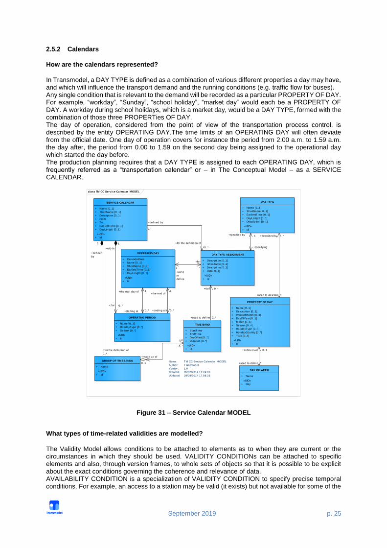
2.5.2 Calendars
How are the calendars represented?
In Transmodel, a DAY TYPE is defined as a combination of various different properties a day may have, and which will influence the transport demand and the running conditions (e.g. traffic flow for buses). Any single condition that is relevant to the demand will be recorded as a particular PROPERTY OF DAY. For example, “workday”, “Sunday”, “school holiday”, “market day” would each be a PROPERTY OF DAY. A workday during school holidays, which is a market day, would be a DAY TYPE, formed with the combination of those three PROPERTies OF DAY. The day of operation, considered from the point of view of the transportation process control, is described by the entity OPERATING DAY.The time limits of an OPERATING DAY will often deviate from the official date. One day of operation covers for instance the period from 2.00 a.m. to 1.59 a.m. the day after, the period from 0.00 to 1.59 on the second day being assigned to the operational day which started the day before. The production planning requires that a DAY TYPE is assigned to each OPERATING DAY, which is frequently referred as a “transportation calendar” or – in The Conceptual Model – as a SERVICE CALENDAR.
Figure 31 – Service Calendar MODEL
What types of time-related validities are modelled?
The Validity Model allows conditions to be attached to elements as to when they are current or the circumstances in which they should be used. VALIDITY CONDITIONs can be attached to specific elements and also, through version frames, to whole sets of objects so that it is possible to be explicit about the exact conditions governing the coherence and relevance of data. AVAILABILITY CONDITION is a specialization of VALIDITY CONDITION to specify precise temporal conditions. For example, an access to a station may be valid (it exists) but not available for some of the
class TM CC Serv ice Calendar MODEL
DAY TYPE
+ Name [0..1]
+ ShortName [0..1]
+ EarliestTime [0..1]
+ DayLength [0..1]
+ Description [0..1]
«UID»
+ Id
OPERATING DAY
+ CalendarDate
+ Name [0..1]
+ ShortName [0..1]
+ EarliestTime [0..1]
+ DayLength [0..1]
«UID»
+ Id
OPERATING PERIOD
+ Name [0..1]
+ HolidayType [0..*]
+ Season [0..*]
«UID»
+ Id
Name: TM CC Service Calendar MODEL
Author: Transmodel
Version: 1.0
Created: 05/02/2014 11:24:00
Updated: 29/08/2014 17:58:35
SERVICE CALENDAR
+ Name [0..1]
+ ShortName [0..1]
+ Description [0..1]
+ From
+ To
+ EarliestTime [0..1]
+ DayLength [0..1]
«UID»
+ Id
DAY TYPE ASSIGNMENT
+ Description [0..1]
+ IsAvailable [0..1]
+ Description [0..1]
+ Date [0..1]
«UID»
+ Id
PROPERTY OF DAY
+ Name [0..1]
+ Description [0..1]
+ WeekOfMonth [0..5]
+ DayOfYear [0..1]
+ Month [0..1]
+ Season [0..4]
+ HolidayType [0..5]
+ HolidayCountry [0..*]
+ Tide [0..4]
«UID»
+ Id
DAY OF WEEK
+ Name
«UID»
+ Day
GROUP OF TIMEBANDS
+ Name
«UID»
+ Id
TIME BAND
+ StartTime
+ EndTime
+ DayOffset [0..*]
+ Duration [0..*]
«UID»
+ Id
+made up of
0..1
+in
0..*
+used to define *
+defined as 0..1
+specifying*
+specified by 1
+the start day of 1
+starting at 0..*
+the end of1
+ending at 0..*
+for the definition of
0..*
+defined
by
1
+defined by
1
+for the definition of
0..*+within
1
+ for 0..*
+used to define 0..*
+for 0..*
+used
to
define
1
+for
*
+used to describe *
+described by *

September 2019 p. 26
time (it is closed between 9 pm and 6 am). An AVAILABILITY CONDITION can be defined by specific DAY TYPEs and/or OPERATING DAYs. It may be further qualified by one or more of TIME BANDs.
2.5.3 Addresses
How can I represent topographic features, like addresses?
A TOPOGRAPHIC PLACE is a type of PLACE providing the topographical context when searching for or presenting travel information, for example as the origin or destination of a trip. It may be of any size (e.g. County,City, Town, Village) and of different specificity (e.g. Greater London, London, West End, Westminster, St James’s). A TOPOGRAPHIC PLACE may be located within one or more COUNTRies. TOPOGRAPHIC PLACEs may overlap. They may also be contained inside another TOPOGRAPHIC PLACE. ADDRESS is the descriptive data associated with a PLACE that can be used to describe the unique geographical context of a PLACE for the purposes of identifying it. May be refined as either a ROAD ADDRESS, a POSTAL ADDRESS or both (Topographic Place Model).
Figure 32 – Topographic Place MODEL
2.5.4 Equipment and Facility
What type of equipment is taken into account?
Transmodel defines a generic concept EQUIPMENT that specialises into INSTALLED EQUIPMENT, an item of equipment either fixed (PLACE EQUIPMENT) or on board i.e. associated with vehicles (ACTUAL VEHICLE EQUIPMENT). PASSENGER EQUIPMENT may be either fixed or on-board. INSTALLED EQUIPMENT is materialised as opposed to a service (LOCAL SERVICE) considered as an immaterial equipment. PLACE EQUIPMENT is described in a very detailed way through a range of concrete classes (cf. Part 2: Waiting & Luggage Equipment, Passenger Service Equipment, Ticketing Equipment, Access Equipment, Sign Equipment Models)
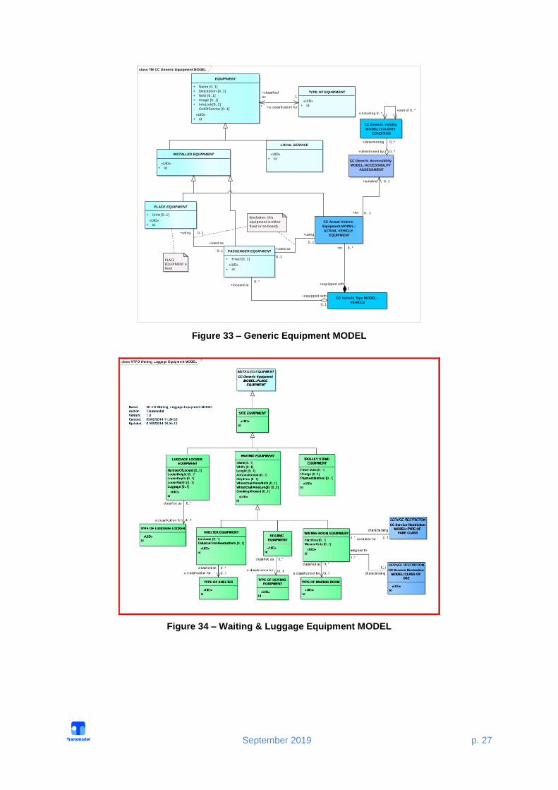
September 2019 p. 27
Figure 33 – Generic Equipment MODEL
Figure 34 – Waiting & Luggage Equipment MODEL
class TM CC Generic Equipment MODEL
PLACE EQUIPMENT
+ Units [0..1]
«UID»
+ Id
EQUIPMENT
+ Name [0..1]
+ Description [0..1]
+ Note [0..1]
+ Image [0..1]
+ InfoLink [0..1]
- OutOfService [0..1]
«UID»
+ Id
LOCAL SERVICE
«UID»
+ Id
INSTALLED EQUIPMENT
«UID»
+ Id
TYPE OF EQUIPMENT
«UID»
+ Id
CC Actual Vehicle
Equipment MODEL::
ACTUAL VEHICLE
EQUIPMENT
PASSENGER EQUIPMENT
+ Fixed [0..1]
«UID»
+ Id
CC Vehicle Type MODEL::
VEHICLE
PLACE
EQUIPMENT is
fixed
CC Generic Accessibility
MODEL::ACCESSIBILITY
ASSESSMENT
CC Generic Validity
MODEL::VALIDITY
CONDITION
{exclusion: this
equipment is either
fixed or on-board}
+located at0..*
+equipped with
0..1
+used as
0..1
+using
0..1
+for 0.. 1
+suitable 0..1
+used as
0..1
+using 0..1
+determining 0..*
+determined by 0..*
+in 0..*
+equipped with
1
+part of 0..*+including 0..*
+a classification for
1
+classified
as
*

September 2019 p. 28
Figure 35 – Passenger Service Equipment MODEL
Figure 36 – Ticketing Equipment MODEL

September 2019 p. 29
Figure 37 – Access Equipment MODEL

September 2019 p. 30
Figure 38 – Sign Equipment MODEL
How is vehicle equipment taken into account?
Vehicle equipment is defined through the entity ACTUAL VEHICLE EQUIPMENT. Two types are particulary important for accessibility VEHICLE ACCESS EQUIPMENT and WHEELCHAIR VEHICLE EQUIPMENT. Specialisations of (on(board) PASSENGER EQUIPMENT are described: ticketing equipment (e.g. TICKET VALIDATOR EQUIPMENT, TICKETING EQUIPMENT) and passenger service equipment (e.g. RUBBISH DISPOSAL, PASSENGER SAFETY EQUIPMENT, SANITARY EQUIPMENT or PASSENGER INFORMATION EQUIPMENT). What is a facility vs. equipment? EQUIPMENT is an item of equipment installed either fixed (PLACE EQUIPMENT) or on-board vehicles (VEHICLE EQUIPMENT). A service (LOCAL SERVICE such as LEFT LUGGAGE, TICKETING SERVICE) is considered as immaterial equipment as well (Generic Equipment Model).

September 2019 p. 31
A named amenity available to the public at a SITE or on a SERVICE. A facility has no further properties other than a name. An EQUIPMENT or LOCAL SERVICE is used to describe the further properties provided as part of particular facility (Facility Model).
Figure 39 – Generic Equipment MODEL

September 2019 p. 32
Figure 40 – Facility MODEL
2.5.5 Vehicle Type and Train
What is a vehicle vs vehicle type?
The VEHICLE entity is used to describe the physical public transport vehicles available for short-term planning of operations and daily assignment (in contrast to logical vehicles considered for resource planning). Each VEHICLE must be classified as of a particular VEHICLE TYPE. The VEHICLE TYPE Model represents a description of VEHICLES through their properties.
Figure 41 – Vehicle type MODEL
How to represent a train? A TRAIN is a VEHICLE TYPE composed of TRAIN ELEMENTs in a certain order, i.e. of wagons assembled together and propelled by a locomotive or one of the wagons.

September 2019 p. 33
Figure 42 – Train MODEL
What type of information is provided by the Vehicle type model?
VEHICLE TYPE is a classification of public transport VEHICLEs according to the vehicle scheduling requirements: in mode and capacity (PASSENGER CARRYING REQUIREMENT, e.g. standard bus, double-deck, ...), and/or as regards maneuvering capabilities (MANOEVRING REQUIREMENT), and/or according to the facilities available on the vehicle (FACILITY REQUIREMENT).

September 2019 p. 34
Figure 43 – Vehicle Type MODEL
class TM CC Vehicle Type MODEL
VEHICLE
+ Name [0..1]
+ ShortName [0..1]
«UID»
+ Id
INSTALLED EQUIPMENT
CC Actual Vehicle Equipment
MODEL::ACTUAL VEHICLE
EQUIPMENT
VEHICLE EQUIPMENT
PROFILE
+ Name [0..1]
+ Units [0..1]
«UID»
+ Id
VEHICLE MODEL
+ Name [0..1]
+ Description [0..1]
+ Manufacturer [0..1]
«UID»
+ Id
VEHICLE TYPE
+ Name [0..1]
+ ShortName [0..1]
+ Description [0..1]
+ ReversingDirection [0..1]
+ SelfPropelled [0..1]
+ Length [0..1]
+ TypeOfFuel [0..1]
+ SeatingCapacity [0..1]
+ StandingCapacity [0..1]
+ SpecialPlaceCapacity [0..1]
+ WheelchairPlaceCapacity [0..1]
+ LowFloor [0..1]
+ HasLiftOrRamp [0..1]
«UID»
+ Id
Name: TM CC Vehicle Type MODEL
Author: Transmodel
Version: 1.0
Created: 05/02/2014 11:24:01
Updated: 29/08/2014 19:05:47
PURPOSE OF EQUIPMENT
PROFILE
«UID»
+ Id
CC Generic Equipment
MODEL::TYPE OF
EQUIPMENT
CC Generic Accessibility
MODEL::ACCESSIBILITY
ASSESSMENT
CC Facility MODEL::
SERVICE FACILITY
SET
CC Facility
MODEL::
FACILITY SET
PASSENGER CARRYING
REQUIREMENT
+ MinimumCapacity
+ LowFloor [0..1]
+ HasLiftOrRamp [0..1]
«UID»
+ Id
MANOEUVRING REQUIREMENT
+ Reversable [0..1]
+ MinimumTurningCircle [0..1]
+ MinimumLength [0..1]
+ MinimumOvertakingWidth [0..1]
«UID»
+ Id
FACILITY REQUIREMENT
+ serviceFacil itySets [0..*]
«UID»
+ Id
+present at
0..*+comprising
0..1
+in 0..*
+equipped with1
+in
1..*
+equipped with
1
+satisfying
0..*
+for
0..*
+ for0..*
+satisfying 0..*
+a classification for 1
+classified
as*
+classifying
0..1+classified
as
*
+made up of 0..1
+included in *
+a classification for 1
+classified as *
+for 0..*
+satisfying 0..*
+for
0.. 1
+suitable
0..1
+requirement for
0..*
+satisfying
+defining 1
+defined
for *
+a classification for 1
+classified
as
*
September 2019 p. 35
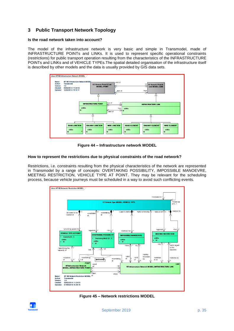
3 Public Transport Network Topology
Is the road network taken into account?
The model of the infrastructure network is very basic and simple in Transmodel, made of INFRASTRUCTURE POINTs and LINKs. It is used to represent specific operational constraints (restrictions) for public transport operation resulting from the characteristics of the INFRASTRUCTURE POINTs and LINKs and of VEHICLE TYPEs.The spatial detailed organisation of the infrastructure itself is described by other models and the data is usually provided by GIS data sets.
Figure 44 – Infrastructure network MODEL
How to represent the restrictions due to physical constraints of the road network?
Restrictions, i.e. constraints resulting from the physical characteristics of the network are represented in Transmodel by a range of concepts: OVERTAKING POSSIBILITY, IMPOSSIBLE MANOEVRE, MEETING RESTRICTION, VEHICLE TYPE AT POINT. They may be relevant for the scheduling process, because vehicle journeys must be scheduled in a way to avoid such conflicting events.
Figure 45 – Network restrictions MODEL

September 2019 p. 36
What is an itinerary in Transmodel?
The term “itinerary” ambiguous as are different types of “itineraries” or “paths” may exist, depending on the purpose to be described: for passengers? for vehicles? along roads? along the rail network? a schematic view? etc. The ROUTE entity represents a conventional way of describing a path through the network, to be used by regular PT services (i.e. vehicles). A ROUTE is defined as an ordered list of located POINTs defining one single path through the road (or rail) network. A ROUTE may pass through the same POINT more than once. ROUTE is a LINK SEQUENCE and must be built in a way that identifies a path without any ambiguity (Line & Route Model). Other specialisations of a LINK SEQUENCE are used to define the work of vehicles: JOURNEY PATTERNs, SERVICE PATTERNs, TIMING PATTERNs (see Tactical Components Model). Passenger “paths” are called NAVIGATION PATHs (Navigation Path Model).
Figure 46 – Line & Route MODEL

September 2019 p. 37
Figure 47 – Navigation Path MODEL
What is a Line vs. a Route?
A ROUTE is a LINK SEQUENCE, defined by an ordered sequence of (two or more) POINTs ON ROUTE. A ROUTE may pass through the same ROUTE POINT more than once, as in the case of a loop. Transmodel defines a LINE as a grouping of ROUTEs that is generally known to the public by a similar name or number. These ROUTEs are usually very similar to each other from the topological point of view, being variants of a core route with some deviations only on certain parts.

September 2019 p. 38
Figure 48 – Line & Route MODEL
Are routing constraints taken into account?
In order to manage competition between operators or bus lines, PT authorities sometimes define ROUTING CONSTRAINTs, preventing passengers boarding or alighting from a vehicle under certain circumstances. Several types of constraints are defined.
Zone based constraints are define by a ROUTING CONSTRAINT ZONE. The ZONE may be defined by its contained SCHEDULED STOP POINTS or by its boundary points. ZONEs are usually used to express constraints like "If you board in this ZONE, you can't alight in the same ZONE", or "only alighting is permitted in this ZONE". The constraint applies to all the POINTs IN JOURNEY PATTERN of specific LINEs included in the ZONE.
A SERVICE EXCLUSION constraint expresses the fact that the service on a specific JOURNEY PATTERN (usually a flexible JOURNEY PATTERN) cannot operate when another (regular) service operates.

September 2019 p. 39
TRANSFER RESTRICTIONs are constraints that can be applied on a CONNECTION or INTERCHANGE between two SCHEDULED STOP POINTs, preventing or forbidding the passenger to make a transfer there.
Figure 49 – Routing constraints MODEL
Can I represent a flexible network?
Transmodel does not have a separate FTS specific model, but has extra properties that can be used to describe FTS systems: FLEXIBLE POINT (LINK) PROPERTIES enabling the definition of a FLEXIBLE ROUTE and a FLEXIBLE LINE. Different types of FTS are considered: Virtual line service, Flexible service with main route, Corridor service (Flexible service without main route), Fixed stop area-wide flexible service, Free area-wide flexible service, Mixed types of flexible service (not at POINT level) (Flexible Network Model). What is a Journey Pattern?
A JOURNEY PATTERN is an ordered list of SCHEDULED STOP POINTs and TIMING POINTs on a single ROUTE, describing the pattern of working for public transport vehicles.A JOURNEY PATTERN may pass through the same POINT more than once (Journey Pattern Model).

September 2019 p. 40
Figure 50 – Journey Pattern MODEL
What is the passenger view of a Journey Pattern?
In the domain of Passenger Information SERVICE PATTERNs are of particular importance, i.e. the specialisation of a JOURNEY PATTERN made up only of (scheduled) STOP POINTs IN JOURNEY PATTERN. Another concept in this context is also relevant: the SERVICE JOURNEY PATTERN, defined as the JOURNEY PATTERN for a (passenger carrying) SERVICE JOURNEY (Service Pattern Model).
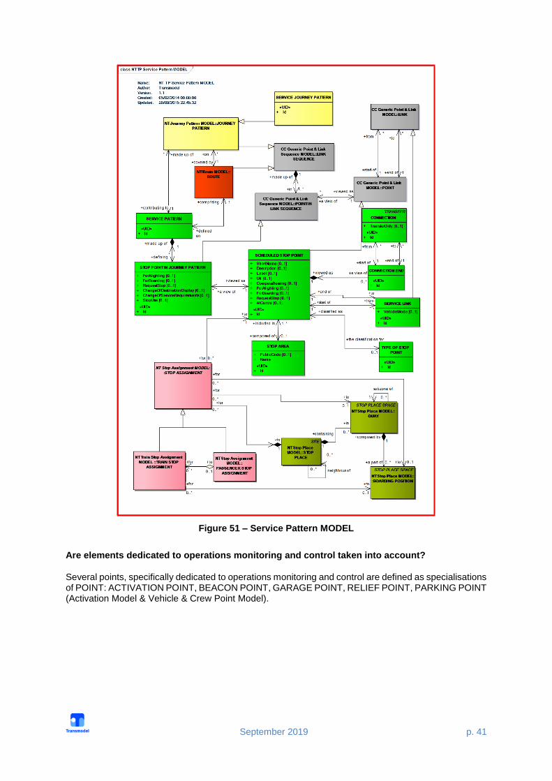
September 2019 p. 41
Figure 51 – Service Pattern MODEL
Are elements dedicated to operations monitoring and control taken into account?
Several points, specifically dedicated to operations monitoring and control are defined as specialisations of POINT: ACTIVATION POINT, BEACON POINT, GARAGE POINT, RELIEF POINT, PARKING POINT (Activation Model & Vehicle & Crew Point Model).

September 2019 p. 42
Figure 52 – Activation MODEL
Figure 53 – Vehicle & Crew Point MODEL
What is a Common Section?

September 2019 p. 43
A part of a public transport network where the ROUTEs of several JOURNEY PATTERNs are going in parallel and where the synchronisation of SERVICE JOURNEYs may be planned and controlled with respect to commonly used LINKs and SCHEDULED STOP POINTs. COMMON SECTIONs are defined arbitrarily and need not cover the total lengths of topologically bundled sections (Common Section Model).
Figure 54 – Common Section MODEL
How can I represent connections with Transmodel?
The physical (spatial) possibility for a passenger to change from one public transport vehicle to another to continue the trip, determined by two SCHEDULED STOP POINTs (Service Connection Model). CONNECTION is a passenger view of a transfer. INTERCHANGE is an operational constraint for a transfer: it is defined as the scheduled possibility for transfer of passengers between two SERVICE JOURNEYs at the same or different SCHEDULED STOP POINTs (Interchange Model).

September 2019 p. 44
Figure 55 – Service Connection MODEL

September 2019 p. 45
Figure 56 – Interchange MODEL
4 Timing Information
How are the time-related aspects of a public transport network taken into account?
One of the main principles of Transmodel is to clearly distinguish the space–related concepts from the time-related concepts. The Reference Data model covers on one hand the topological aspects of the Public Transport Network, on the other hand, time-related aspects. The time-related concepts are presented in the Service Calendar model (Part 1 – Common Concepts), Time Demand Type Model (Part 2 – Tactical Planning Components) and in the Timing Information Model (Part 3 – Timing Information and Vehicle Scheduling).
What are the main Tactical Planning Components?
The Tactical Planning Components Model provides reusable information about transport planning, such as spatial description of journey patterns and service patterns. Reusable journey patterns and service patterns are independent of actual operating times in scheduled journeys.
September 2019 p. 46
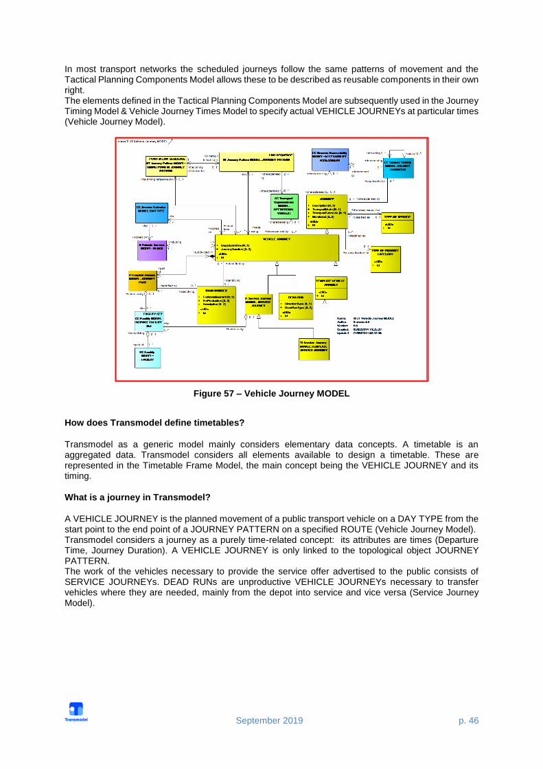
In most transport networks the scheduled journeys follow the same patterns of movement and the Tactical Planning Components Model allows these to be described as reusable components in their own right. The elements defined in the Tactical Planning Components Model are subsequently used in the Journey Timing Model & Vehicle Journey Times Model to specify actual VEHICLE JOURNEYs at particular times (Vehicle Journey Model).
Figure 57 – Vehicle Journey MODEL
How does Transmodel define timetables?
Transmodel as a generic model mainly considers elementary data concepts. A timetable is an aggregated data. Transmodel considers all elements available to design a timetable. These are represented in the Timetable Frame Model, the main concept being the VEHICLE JOURNEY and its timing.
What is a journey in Transmodel?
A VEHICLE JOURNEY is the planned movement of a public transport vehicle on a DAY TYPE from the start point to the end point of a JOURNEY PATTERN on a specified ROUTE (Vehicle Journey Model). Transmodel considers a journey as a purely time-related concept: its attributes are times (Departure Time, Journey Duration). A VEHICLE JOURNEY is only linked to the topological object JOURNEY PATTERN. The work of the vehicles necessary to provide the service offer advertised to the public consists of SERVICE JOURNEYs. DEAD RUNs are unproductive VEHICLE JOURNEYs necessary to transfer vehicles where they are needed, mainly from the depot into service and vice versa (Service Journey Model).

September 2019 p. 47
Figure 58 – Service Journey MODEL
Does Transmodel describe journey coupling and splitting?
Transmodel considers different concepts (Coupled Journey Model):
a COUPLED JOURNEY: A complete journey operated by a coupled train, composed of two or
more VEHICLE JOURNEYs remaining coupled together all along a JOURNEY PATTERN. A
COUPLED JOURNEY may be viewed as a single VEHICLE JOURNEY.
JOURNEY PARTs: A part of a VEHICLE JOURNEY created according to a specific functional
purpose, for instance in situations when vehicle coupling or separating occurs.
A JOURNEY PART COUPLE: two JOURNEY PARTs of different VEHICLE JOURNEYs
served simultaneously by a train set up by coupling their single vehicles.

September 2019 p. 48
Figure 59 – Coupled Journey MODEL
How is journey timing considered in Transmodel?
Basically the following situations are possible:
Representation of journey timing as PASSING TIMEs (at specific points) derived from the run
times (times taken to traverse TIMING LINKs within the JOURNEY PATTERN related to the
VEHICLE JOURNEY)
Consideration of DEFAULT run time : the default time taken by a vehicle to traverse a TIMING LINK for a specified TIME DEMAND TYPE (Time Demand Times Model)
Consideration of JOURNEY PATTERN RUN TIME: the time taken to traverse a TIMING LINK in a particular JOURNEY PATTERN, for a specified TIME DEMAND TYPE. (Journey Pattern Times Model)
Consideration of specific run times for each particular VEHICLE JOURNEY (Vehicle Journey Times Model)
Representation of a special behaviour of journeys
frequency based services (services runing with a regular interval (every 10 mn, for example)
rhythmical services (runs all xxh10, xxh25 and xxh45, for example)

September 2019 p. 49
Figure 60 – Time Demand Times MODEL

September 2019 p. 50
Figure 61 – Journey Pattern Times MODEL

September 2019 p. 51
Figure 62 – Vehicle Journey Times MODEL
Are passing times at stops defined?
Strictly speaking Transmodel differentiates space-related concepts from time-related concepts. So the PASSING TIMES are linked to vehicle journeys. Two main types of PASSING TIMEs do exist: a set of TIMETABLED PASSING TIMEs is linked to a VEHICLE JOURNEY and a set of DATED PASSING TIMEs is linked to a DATED VEHICLE JOURNEY. Several considerations have then to be undertaken, to calculate the timing of a journey, based on a reference TIMING POINT belonging to the covered JOURNEY PATTERN where a ‘departure time’ is specified for the journey at this point, then run and wait times for the different TIMING LINKS (possibly depending on the TIME DEMAND TYPE) have to be considered to determine the PASSING TIMEs at TIMING POINTs . The PASSING TIMEs at stops which are not TIMING POINTs may be determined by interpolation.
Are Demand Responsive Services taken into account?
Transmodel considers flexibility of services through the assignment of FLEXIBLE SERVICE PROPERTIES to VEHICLE JOURNEYs (Flexible Service Model).

September 2019 p. 52
Figure 63 – Flexible Service MODEL
How does Transmodel represent scheduled interchanges?
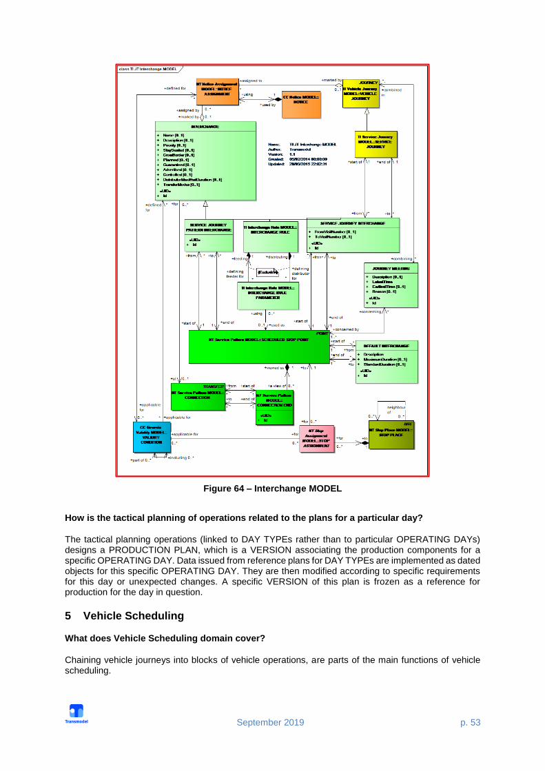
INTERCHANGE is the scheduled possibility for transfer of passengers between two SERVICE JOURNEYs at the same or different SCHEDULED STOP POINTs (Interchange Model). INTERCHANGE RULES describe conditions for considering JOURNEYs to meet or not to meet, specified indirectly: by a particular MODE, DIRECTION or LINE. Such conditions may alternatively be specified directly, indicating the corresponding services. In this case they are either a SERVICE JOURNEY PATTERN INTERCHANGE or a SERVICE JOURNEY INTERCHANGE. INTERCHANGE has to be differentiated from the concept of CONNECTION. Scheduled INTERCHANGEs represent operational time constraints for journeys to meet. CONNECTION represents the spatial possibility for a passenger to change from one public transport vehicle to another to continue the trip.
September 2019 p. 53
Figure 64 – Interchange MODEL
How is the tactical planning of operations related to the plans for a particular day?
The tactical planning operations (linked to DAY TYPEs rather than to particular OPERATING DAYs) designs a PRODUCTION PLAN, which is a VERSION associating the production components for a specific OPERATING DAY. Data issued from reference plans for DAY TYPEs are implemented as dated objects for this specific OPERATING DAY. They are then modified according to specific requirements for this day or unexpected changes. A specific VERSION of this plan is frozen as a reference for production for the day in question.
5 Vehicle Scheduling
What does Vehicle Scheduling domain cover?
Chaining vehicle journeys into blocks of vehicle operations, are parts of the main functions of vehicle scheduling.

September 2019 p. 54
The corresponding entities and relationships included in the reference data model allow a comprehensive description of the data needs associated with this functionality, independently of the particular methods and algorithms applied by the different software systems.
What is a Vehicle Service?
A VEHICLE SERVICE is the workplan for a vehicle for a whole day, planned for a specific DAY TYPE.
What is a Block?
A BLOCK is the work of a vehicle from the time it leaves a PARKING POINT after parking until its next return to park at a PARKING POINT. Any subsequent departure from a PARKING POINT after parking marks the start of a new BLOCK.
A BLOCK includes in particular all VEHICLE JOURNEYs (SERVICE JOURNEYs and DEAD RUNs) planned for this period. It also may include SPECIAL SERVICEs. Between two journeys or services, a pause may be Linked to this concept is the concept of COURSE OF JOURNEYS: a part of a BLOCK composed of consecutive VEHICLE JOURNEYs defined for the same DAY TYPE, all operated on the same LINE.
How does Transmodel represent vehicle services for rail operation?
Vehicles of the type TRAIN or COMPOUND TRAIN may be coupled or separated. As regards the corresponding journeys, COUPLED JOURNEYs or JOURNEY PARTs are created.
A BLOCK PART is a part of a BLOCK corresponding to the different JOURNEY PARTs of the VEHICLE JOURNEYs in a BLOCK.
One or several vehicle BLOCKs may be coupled together for a while. The entity COMPOUND BLOCK represents the work of a vehicle during the time it is coupled to one or more vehicles. If two different vehicles are coupled at a certain point (e.g. a terminus), a COMPOUND BLOCK is created from that instant on. If this COMPOUND BLOCK is joined by a third BLOCK, coupled later at another point COMPOUND BLOCK, a new COMPOUND BLOCK is formed from that instant on. If one of the BLOCKs is separated before the COMPOUND BLOCK returns to the GARAGE, another COMPOUND BLOCK is formed, composed of the two BLOCKs corresponding to the coupled vehicles.


![Common Harmonic Improvement Concepts...1979/10/14 · Common Harmonic Improvement Concepts Ted Greene — 1979, October 14 [Ted’s note to himself about teaching this page:] Show](https://static.fdocuments.net/doc/165x107/5e87784b4d71975aa254fba3/common-harmonic-improvement-concepts-19791014-common-harmonic-improvement.jpg)


